Embed Size (px)
Citation preview
v2000.05 HDL Compiler for Verilog Reference Manual
9HDL Compiler Directives 9
The Synopsys Verilog HDL Compiler translates a Verilog descriptionto the internal format Design Compiler uses. Specific aspects of thisprocess can be controlled by special comments in the Verilog sourcecode called HDL Compiler directives. Because these directives area special case of regular comments, they are ignored by the VerilogHDL Simulator and do not affect simulation.
This chapter describes HDL Compiler directives and their effect ontranslation, in the following sections:
• Verilog Preprocessor Directives
• Notation for HDL Compiler Directives
• translate_off and translate_on Directives
• parallel_case Directive
• full_case Directive
/ 9-1HOME CONTENTS INDEX
v2000.05 HDL Compiler for Verilog Reference Manual
• state_vector Directive
• enum Directive
• template Directive
• Embedding Constraints and Attributes
• Component Implication
Verilog Preprocessor Directives
Verilog preprocessing provides the following features:
• -define option to the analyze command
• dc_shell variables
• The ‘ifdef , ‘else , and ‘endif directives
• The DC Macro
• Extended capabilities for the ‘define directive
Define Option to the analyze Command
An option to the analyze command, -define (or -d , abbreviated),allows macro definition on the command line.
You can use only one -define per analyze command. But theargument can be a list of macros, as shown in Example 9-1.
You do not need to use curly brackets to enclose one macro, as shownin Example 9-2.
/ 9-2HOME CONTENTS INDEX
v2000.05 HDL Compiler for Verilog Reference Manual
Example 9-1 analyze Command With List of Definesanalyze -f verilog -d { RIPPLE, SIMPLE } mydesign.v
Example 9-2 analyze Command With One Defineanalyze -f verilog -define ONLY_ONE mydesign.v
Note:The read command does not accept the -d option.
The input to the analyze command continues to be a Verilog file.The output of the analyze command continues to be a .syn file.
dc_shell Variables
These variables perform the following functions:
hdlin_preserve_vpp_files
By default, this variable is false. When it is false, intermediatepreprocessor files are deleted after use.
Preprocessor files are preserved (not deleted) when this flag isset to true.
hdlin_vpp_temporary_directory
Indicates where the intermediate preprocessor files are created.The default is to use the user’s WORK directory.
hdlin_enable_vpp
When set to true (the default), hdlin_enable_vpp allowsinterpretation of the ‘ifdef , ‘else , and ‘endif directives.
It also activates ‘define extensions, which allow macros witharguments.
/ 9-3HOME CONTENTS INDEX
v2000.05 HDL Compiler for Verilog Reference Manual
‘ifdef, ‘else, and ‘endif Directives
The ‘ifdef , ‘else , and ‘endif directives allow the conditionalinclusion of code.
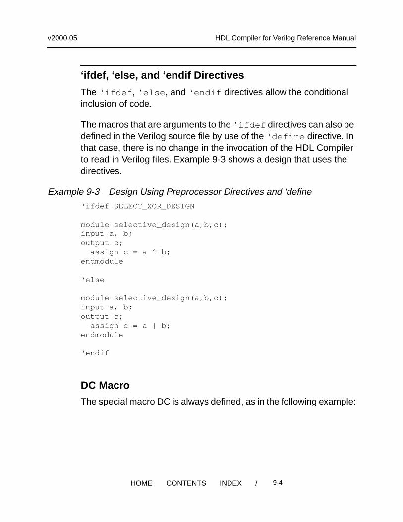
The macros that are arguments to the ‘ifdef directives can also bedefined in the Verilog source file by use of the ‘define directive. Inthat case, there is no change in the invocation of the HDL Compilerto read in Verilog files. Example 9-3 shows a design that uses thedirectives.
Example 9-3 Design Using Preprocessor Directives and ‘define‘ifdef SELECT_XOR_DESIGN
module selective_design(a,b,c);input a, b;output c; assign c = a ^ b;endmodule
‘else
module selective_design(a,b,c);input a, b;output c; assign c = a | b;endmodule
‘endif
DC Macro
The special macro DC is always defined, as in the following example:
/ 9-4HOME CONTENTS INDEX
v2000.05 HDL Compiler for Verilog Reference Manual
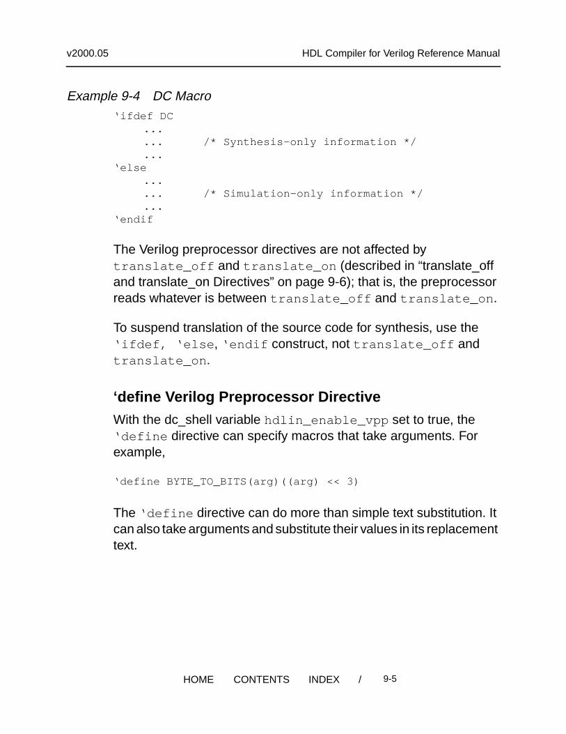
Example 9-4 DC Macro‘ifdef DC
...
... /* Synthesis-only information */
...‘else
...
... /* Simulation-only information */
...‘endif
The Verilog preprocessor directives are not affected bytranslate_off and translate_on (described in “translate_offand translate_on Directives” on page 9-6); that is, the preprocessorreads whatever is between translate_off and translate_on .
To suspend translation of the source code for synthesis, use the‘ifdef, ‘else , ‘endif construct, not translate_off andtranslate_on .
‘define Verilog Preprocessor Directive
With the dc_shell variable hdlin_enable_vpp set to true, the‘define directive can specify macros that take arguments. Forexample,
‘define BYTE_TO_BITS(arg)((arg) << 3)
The ‘define directive can do more than simple text substitution. Itcan also take arguments and substitute their values in its replacementtext.
/ 9-5HOME CONTENTS INDEX
v2000.05 HDL Compiler for Verilog Reference Manual
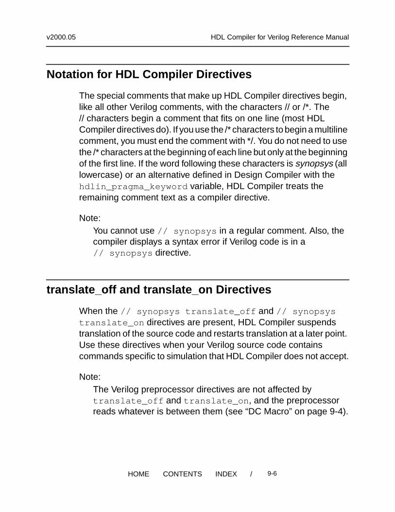
Notation for HDL Compiler Directives
The special comments that make up HDL Compiler directives begin,like all other Verilog comments, with the characters // or /*. The// characters begin a comment that fits on one line (most HDLCompiler directives do). If you use the /* characters to begin a multilinecomment, you must end the comment with */. You do not need to usethe /* characters at the beginning of each line but only at the beginningof the first line. If the word following these characters is synopsys (alllowercase) or an alternative defined in Design Compiler with thehdlin_pragma_keyword variable, HDL Compiler treats theremaining comment text as a compiler directive.
Note:You cannot use // synopsys in a regular comment. Also, thecompiler displays a syntax error if Verilog code is in a// synopsys directive.
translate_off and translate_on Directives
When the // synopsys translate_off and // synopsystranslate_on directives are present, HDL Compiler suspendstranslation of the source code and restarts translation at a later point.Use these directives when your Verilog source code containscommands specific to simulation that HDL Compiler does not accept.
Note:The Verilog preprocessor directives are not affected bytranslate_off and translate_on , and the preprocessorreads whatever is between them (see “DC Macro” on page 9-4).
/ 9-6HOME CONTENTS INDEX
v2000.05 HDL Compiler for Verilog Reference Manual
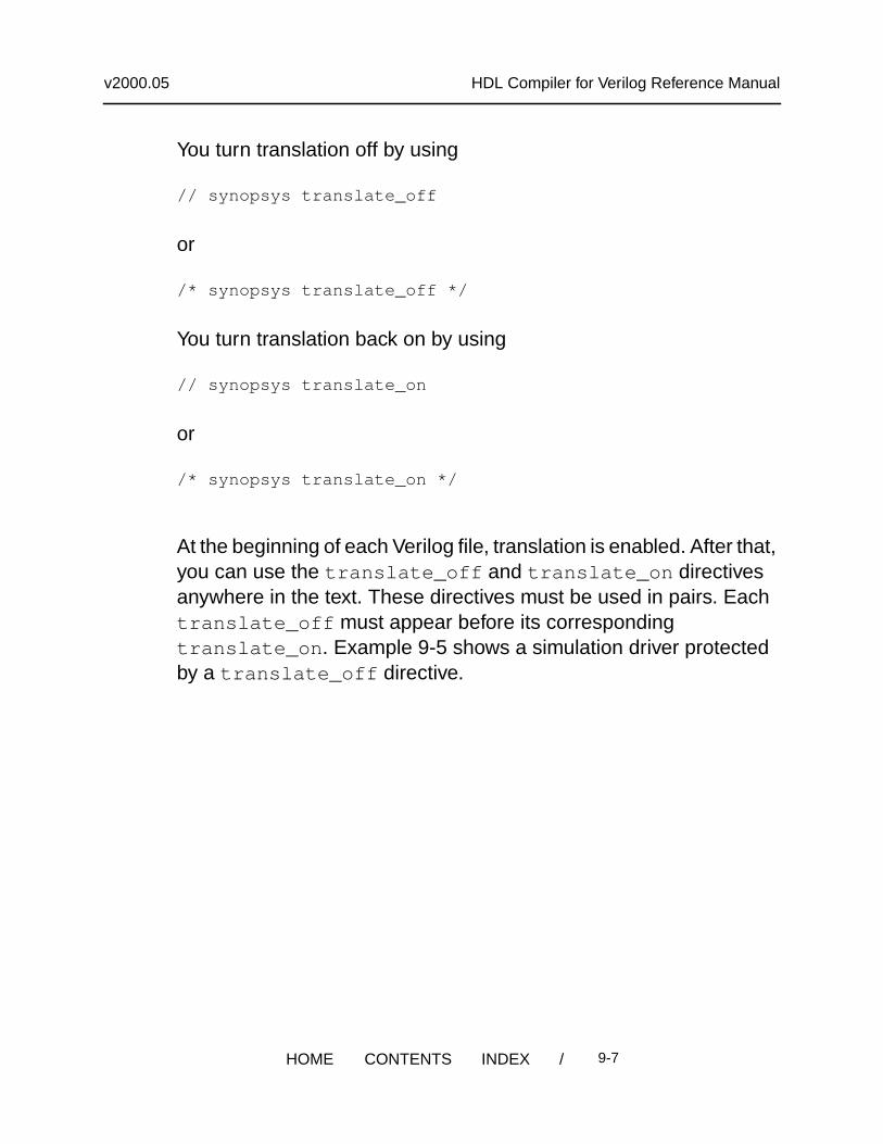
You turn translation off by using
// synopsys translate_off
or
/* synopsys translate_off */
You turn translation back on by using
// synopsys translate_on
or
/* synopsys translate_on */
At the beginning of each Verilog file, translation is enabled. After that,you can use the translate_off and translate_on directivesanywhere in the text. These directives must be used in pairs. Eachtranslate_off must appear before its correspondingtranslate_on . Example 9-5 shows a simulation driver protectedby a translate_off directive.
/ 9-7HOME CONTENTS INDEX
v2000.05 HDL Compiler for Verilog Reference Manual
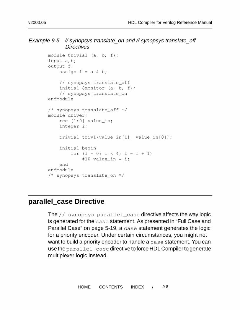
Example 9-5 // synopsys translate_on and // synopsys translate_offDirectives
module trivial (a, b, f);input a,b;output f; assign f = a & b;
// synopsys translate_off initial $monitor (a, b, f); // synopsys translate_onendmodule
/* synopsys translate_off */module driver; reg [1:0] value_in; integer i;
trivial triv1(value_in[1], value_in[0]);
initial begin for (i = 0; i < 4; i = i + 1) #10 value_in = i; endendmodule/* synopsys translate_on */
parallel_case Directive
The // synopsys parallel_case directive affects the way logicis generated for the case statement. As presented in “Full Case andParallel Case” on page 5-19, a case statement generates the logicfor a priority encoder. Under certain circumstances, you might notwant to build a priority encoder to handle a case statement. You canuse the parallel_case directive to force HDL Compiler to generatemultiplexer logic instead.
/ 9-8HOME CONTENTS INDEX
v2000.05 HDL Compiler for Verilog Reference Manual
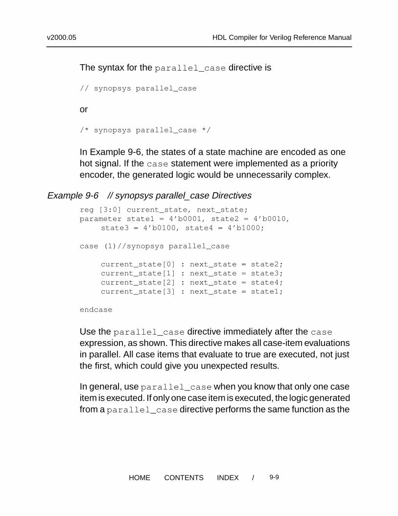
The syntax for the parallel_case directive is
// synopsys parallel_case
or
/* synopsys parallel_case */
In Example 9-6, the states of a state machine are encoded as onehot signal. If the case statement were implemented as a priorityencoder, the generated logic would be unnecessarily complex.
Example 9-6 // synopsys parallel_case Directivesreg [3:0] current_state, next_state;parameter state1 = 4’b0001, state2 = 4’b0010,
state3 = 4’b0100, state4 = 4’b1000;
case (1)//synopsys parallel_case
current_state[0] : next_state = state2;current_state[1] : next_state = state3;current_state[2] : next_state = state4;current_state[3] : next_state = state1;
endcase
Use the parallel_case directive immediately after the caseexpression, as shown. This directive makes all case-item evaluationsin parallel. All case items that evaluate to true are executed, not justthe first, which could give you unexpected results.
In general, use parallel_case when you know that only one caseitem is executed. If only one case item is executed, the logic generatedfrom a parallel_case directive performs the same function as the
/ 9-9HOME CONTENTS INDEX
v2000.05 HDL Compiler for Verilog Reference Manual
circuit when it is simulated. If two case items are executed and youhave used the parallel_case directive, the generated logic is notthe same as the simulated description.
full_case Directive
The // synopsys full_case directive asserts that all possibleclauses of a case statement have been covered and that no defaultclause is necessary. This directive has two uses: It avoids the needfor default logic, and it can avoid latch inference from a casestatement by asserting that all necessary conditions are covered bythe given branches of the case statement. As shown in “Full Caseand Parallel Case” on page 5-19, a latch can be inferred whenever avariable is not assigned a value under all conditions.
The syntax for the full_case directive is
// synopsys full_case
or
/* synopsys full_case */
If the case statement contains a default clause, HDL Compilerassumes that all conditions are covered. If there is no default clauseand you do not want latches to be created, use the full_casedirective to indicate that all necessary conditions are described in thecase statement.
Example 9-7 shows two uses of full_case . The parallel_caseand full_case directives can be combined in one comment.
/ 9-10HOME CONTENTS INDEX
v2000.05 HDL Compiler for Verilog Reference Manual
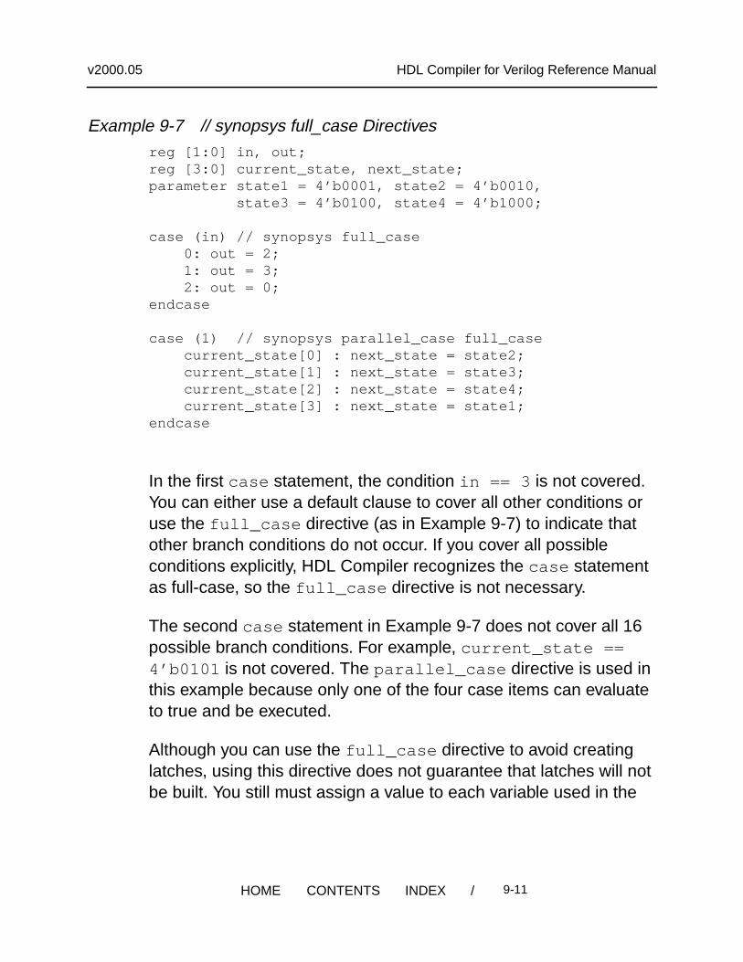
Example 9-7 // synopsys full_case Directivesreg [1:0] in, out;reg [3:0] current_state, next_state;parameter state1 = 4’b0001, state2 = 4’b0010, state3 = 4’b0100, state4 = 4’b1000;
case (in) // synopsys full_case 0: out = 2; 1: out = 3; 2: out = 0;endcase
case (1) // synopsys parallel_case full_case current_state[0] : next_state = state2; current_state[1] : next_state = state3; current_state[2] : next_state = state4; current_state[3] : next_state = state1;endcase
In the first case statement, the condition in == 3 is not covered.You can either use a default clause to cover all other conditions oruse the full_case directive (as in Example 9-7) to indicate thatother branch conditions do not occur. If you cover all possibleconditions explicitly, HDL Compiler recognizes the case statementas full-case, so the full_case directive is not necessary.
The second case statement in Example 9-7 does not cover all 16possible branch conditions. For example, current_state ==4’b0101 is not covered. The parallel_case directive is used inthis example because only one of the four case items can evaluateto true and be executed.
Although you can use the full_case directive to avoid creatinglatches, using this directive does not guarantee that latches will notbe built. You still must assign a value to each variable used in the
/ 9-11HOME CONTENTS INDEX
v2000.05 HDL Compiler for Verilog Reference Manual
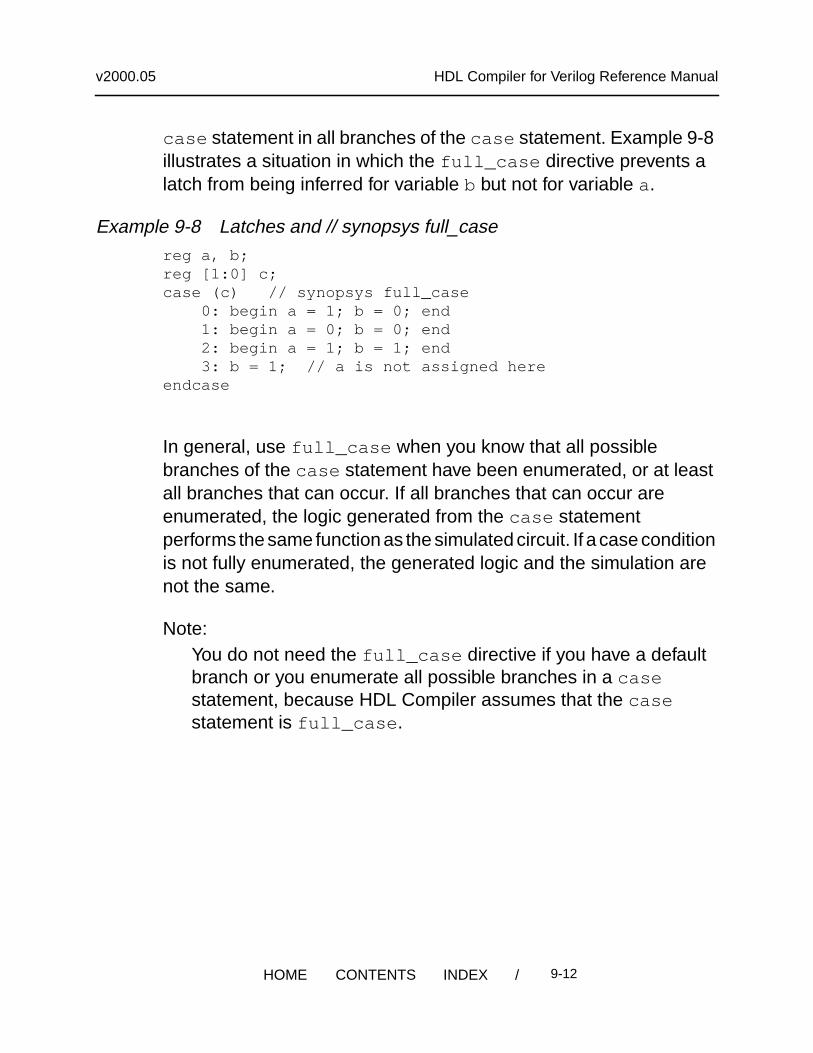
case statement in all branches of the case statement. Example 9-8illustrates a situation in which the full_case directive prevents alatch from being inferred for variable b but not for variable a.
Example 9-8 Latches and // synopsys full_casereg a, b;reg [1:0] c;case (c) // synopsys full_case 0: begin a = 1; b = 0; end 1: begin a = 0; b = 0; end 2: begin a = 1; b = 1; end 3: b = 1; // a is not assigned hereendcase
In general, use full_case when you know that all possiblebranches of the case statement have been enumerated, or at leastall branches that can occur. If all branches that can occur areenumerated, the logic generated from the case statementperforms the same function as the simulated circuit. If a case conditionis not fully enumerated, the generated logic and the simulation arenot the same.
Note:You do not need the full_case directive if you have a defaultbranch or you enumerate all possible branches in a casestatement, because HDL Compiler assumes that the casestatement is full_case .
/ 9-12HOME CONTENTS INDEX
v2000.05 HDL Compiler for Verilog Reference Manual
state_vector Directive
The // synopsys state_vector directive labels a variable in aVerilog description as the state vector of an equivalent finite statemachine.
The syntax for the state_vector directive is
// synopsys state_vector vector_name
or
/* synopsys state_vector vector_name */
The vector_name variable is the name chosen as a state vector.This declaration allows Synopsys Design Compiler to extract thelabeled state vector from the Verilog description. Used with the enumdirective, described in the next section, the state_vector directiveallows you to define the state vector of a finite state machine (and itsencodings) from a Verilog description. Example 9-9 shows one wayto use the state_vector directive.
Caution!Do not define two state_vector directives in one module.Although Design Compiler does not issue an error message, itrecognizes only the first state_vector directive and ignores thesecond.
/ 9-13HOME CONTENTS INDEX
v2000.05 HDL Compiler for Verilog Reference Manual
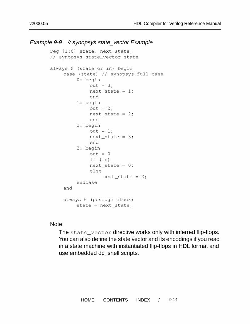
Example 9-9 // synopsys state_vector Examplereg [1:0] state, next_state;// synopsys state_vector state
always @ (state or in) begincase (state) // synopsys full_case
0: beginout = 3;next_state = 1;end
1: beginout = 2;next_state = 2;end
2: beginout = 1;next_state = 3;end
3: beginout = 0if (in)next_state = 0;else
next_state = 3;endcase
end
always @ (posedge clock)state = next_state;
Note:The state_vector directive works only with inferred flip-flops.You can also define the state vector and its encodings if you readin a state machine with instantiated flip-flops in HDL format anduse embedded dc_shell scripts.
/ 9-14HOME CONTENTS INDEX
v2000.05 HDL Compiler for Verilog Reference Manual
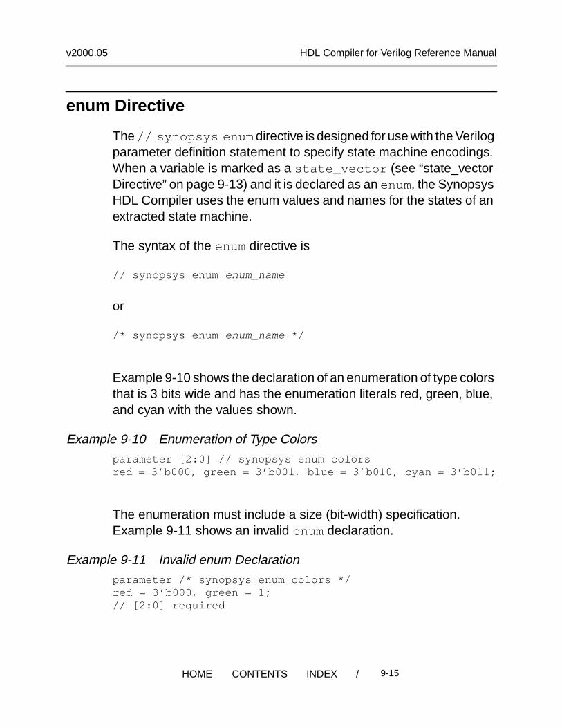
enum Directive
The // synopsys enum directive is designed for use with the Verilogparameter definition statement to specify state machine encodings.When a variable is marked as a state_vector (see “state_vectorDirective” on page 9-13) and it is declared as an enum, the SynopsysHDL Compiler uses the enum values and names for the states of anextracted state machine.
The syntax of the enum directive is
// synopsys enum enum_name
or
/* synopsys enum enum_name */
Example 9-10 shows the declaration of an enumeration of type colorsthat is 3 bits wide and has the enumeration literals red, green, blue,and cyan with the values shown.
Example 9-10 Enumeration of Type Colorsparameter [2:0] // synopsys enum colorsred = 3’b000, green = 3’b001, blue = 3’b010, cyan = 3’b011;
The enumeration must include a size (bit-width) specification.Example 9-11 shows an invalid enum declaration.
Example 9-11 Invalid enum Declarationparameter /* synopsys enum colors */red = 3’b000, green = 1;// [2:0] required
/ 9-15HOME CONTENTS INDEX
v2000.05 HDL Compiler for Verilog Reference Manual
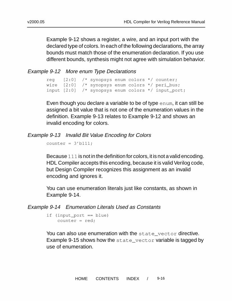
Example 9-12 shows a register, a wire, and an input port with thedeclared type of colors. In each of the following declarations, the arraybounds must match those of the enumeration declaration. If you usedifferent bounds, synthesis might not agree with simulation behavior.
Example 9-12 More enum Type Declarationsreg [2:0] /* synopsys enum colors */ counter;wire [2:0] /* synopsys enum colors */ peri_bus;input [2:0] /* synopsys enum colors */ input_port;
Even though you declare a variable to be of type enum, it can still beassigned a bit value that is not one of the enumeration values in thedefinition. Example 9-13 relates to Example 9-12 and shows aninvalid encoding for colors.
Example 9-13 Invalid Bit Value Encoding for Colorscounter = 3’b111;
Because 111 is not in the definition for colors, it is not a valid encoding.HDL Compiler accepts this encoding, because it is valid Verilog code,but Design Compiler recognizes this assignment as an invalidencoding and ignores it.
You can use enumeration literals just like constants, as shown inExample 9-14.
Example 9-14 Enumeration Literals Used as Constantsif (input_port == blue) counter = red;
You can also use enumeration with the state_vector directive.Example 9-15 shows how the state_vector variable is tagged byuse of enumeration.
/ 9-16HOME CONTENTS INDEX
v2000.05 HDL Compiler for Verilog Reference Manual
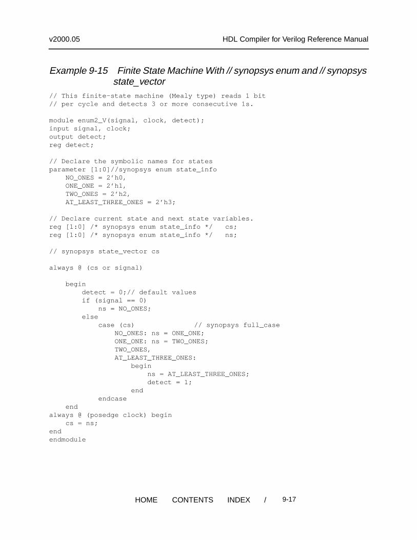
Example 9-15 Finite State Machine With // synopsys enum and // synopsysstate_vector
// This finite-state machine (Mealy type) reads 1 bit// per cycle and detects 3 or more consecutive 1s.
module enum2_V(signal, clock, detect);input signal, clock;output detect;reg detect;
// Declare the symbolic names for statesparameter [1:0]//synopsys enum state_info NO_ONES = 2’h0, ONE_ONE = 2’h1, TWO_ONES = 2’h2, AT_LEAST_THREE_ONES = 2’h3;
// Declare current state and next state variables.reg [1:0] /* synopsys enum state_info */ cs;reg [1:0] /* synopsys enum state_info */ ns;
// synopsys state_vector cs
always @ (cs or signal)
begin detect = 0;// default values if (signal == 0) ns = NO_ONES; else case (cs) // synopsys full_case NO_ONES: ns = ONE_ONE; ONE_ONE: ns = TWO_ONES; TWO_ONES, AT_LEAST_THREE_ONES: begin ns = AT_LEAST_THREE_ONES; detect = 1; end endcase endalways @ (posedge clock) begin cs = ns;endendmodule
/ 9-17HOME CONTENTS INDEX
v2000.05 HDL Compiler for Verilog Reference Manual
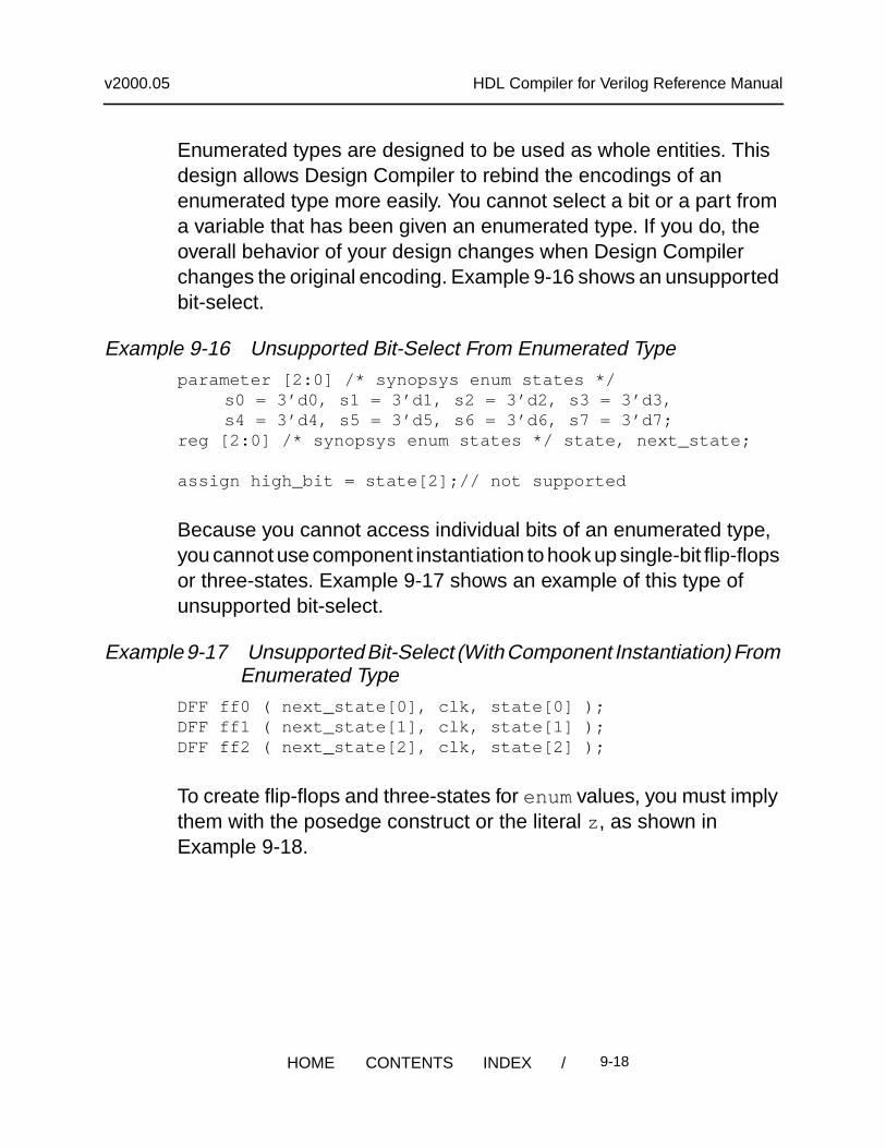
Enumerated types are designed to be used as whole entities. Thisdesign allows Design Compiler to rebind the encodings of anenumerated type more easily. You cannot select a bit or a part froma variable that has been given an enumerated type. If you do, theoverall behavior of your design changes when Design Compilerchanges the original encoding. Example 9-16 shows an unsupportedbit-select.
Example 9-16 Unsupported Bit-Select From Enumerated Typeparameter [2:0] /* synopsys enum states */
s0 = 3’d0, s1 = 3’d1, s2 = 3’d2, s3 = 3’d3,s4 = 3’d4, s5 = 3’d5, s6 = 3’d6, s7 = 3’d7;
reg [2:0] /* synopsys enum states */ state, next_state;
assign high_bit = state[2];// not supported
Because you cannot access individual bits of an enumerated type,you cannot use component instantiation to hook up single-bit flip-flopsor three-states. Example 9-17 shows an example of this type ofunsupported bit-select.
Example 9-17 Unsupported Bit-Select (With Component Instantiation) FromEnumerated Type
DFF ff0 ( next_state[0], clk, state[0] );DFF ff1 ( next_state[1], clk, state[1] );DFF ff2 ( next_state[2], clk, state[2] );
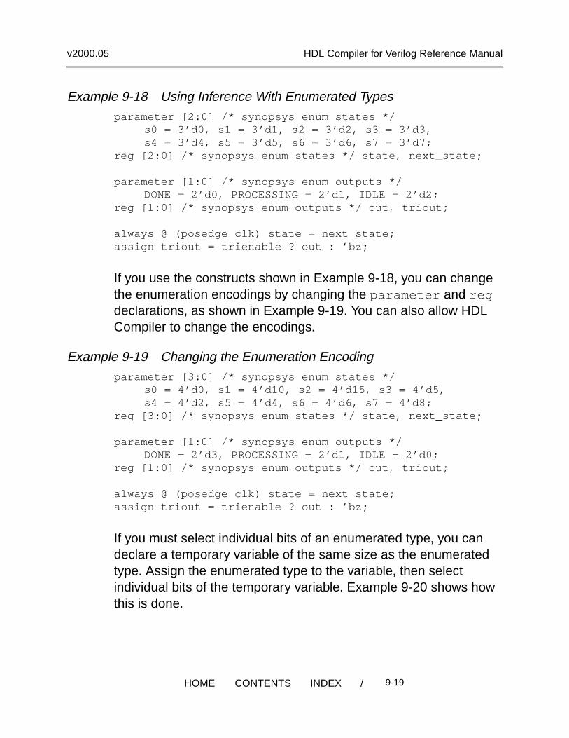
To create flip-flops and three-states for enumvalues, you must implythem with the posedge construct or the literal z , as shown inExample 9-18.
/ 9-18HOME CONTENTS INDEX
v2000.05 HDL Compiler for Verilog Reference Manual
Example 9-18 Using Inference With Enumerated Typesparameter [2:0] /* synopsys enum states */
s0 = 3’d0, s1 = 3’d1, s2 = 3’d2, s3 = 3’d3,s4 = 3’d4, s5 = 3’d5, s6 = 3’d6, s7 = 3’d7;
reg [2:0] /* synopsys enum states */ state, next_state;
parameter [1:0] /* synopsys enum outputs */DONE = 2’d0, PROCESSING = 2’d1, IDLE = 2’d2;
reg [1:0] /* synopsys enum outputs */ out, triout;
always @ (posedge clk) state = next_state;assign triout = trienable ? out : ’bz;
If you use the constructs shown in Example 9-18, you can changethe enumeration encodings by changing the parameter and regdeclarations, as shown in Example 9-19. You can also allow HDLCompiler to change the encodings.
Example 9-19 Changing the Enumeration Encodingparameter [3:0] /* synopsys enum states */
s0 = 4’d0, s1 = 4’d10, s2 = 4’d15, s3 = 4’d5,s4 = 4’d2, s5 = 4’d4, s6 = 4’d6, s7 = 4’d8;
reg [3:0] /* synopsys enum states */ state, next_state;
parameter [1:0] /* synopsys enum outputs */DONE = 2’d3, PROCESSING = 2’d1, IDLE = 2’d0;
reg [1:0] /* synopsys enum outputs */ out, triout;
always @ (posedge clk) state = next_state;assign triout = trienable ? out : ’bz;
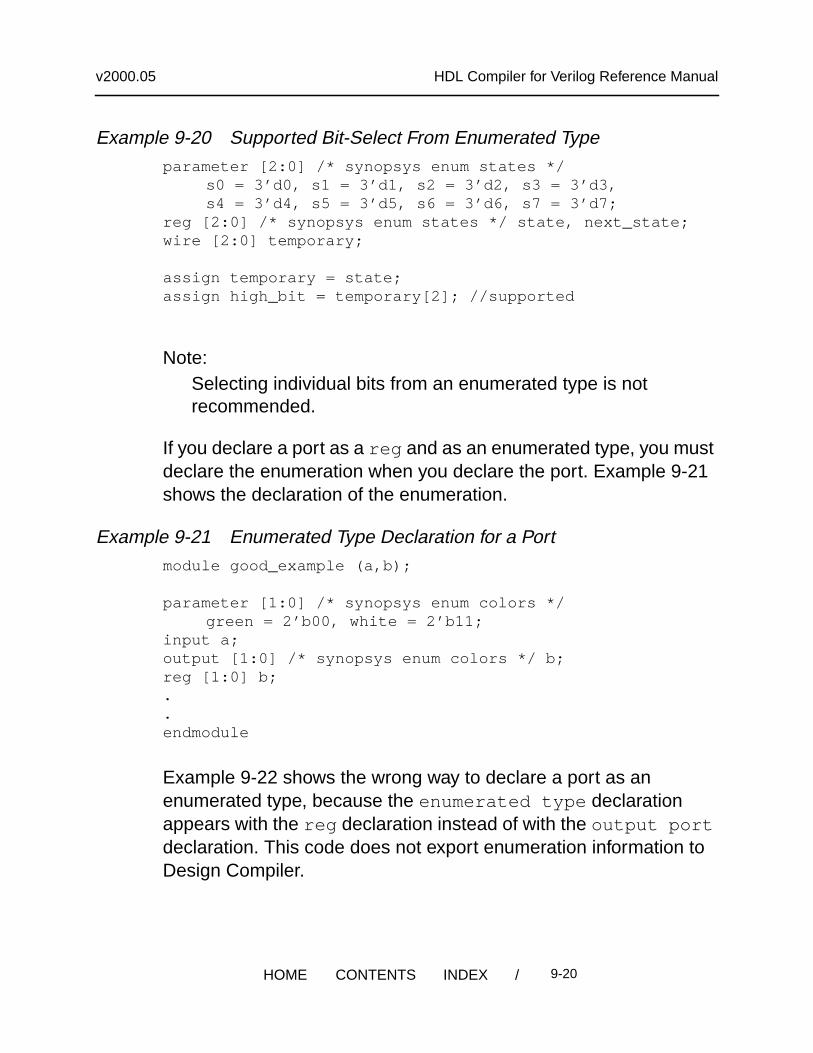
If you must select individual bits of an enumerated type, you candeclare a temporary variable of the same size as the enumeratedtype. Assign the enumerated type to the variable, then selectindividual bits of the temporary variable. Example 9-20 shows howthis is done.
/ 9-19HOME CONTENTS INDEX
v2000.05 HDL Compiler for Verilog Reference Manual
Example 9-20 Supported Bit-Select From Enumerated Typeparameter [2:0] /* synopsys enum states */
s0 = 3’d0, s1 = 3’d1, s2 = 3’d2, s3 = 3’d3,s4 = 3’d4, s5 = 3’d5, s6 = 3’d6, s7 = 3’d7;
reg [2:0] /* synopsys enum states */ state, next_state;wire [2:0] temporary;
assign temporary = state;assign high_bit = temporary[2]; //supported
Note:Selecting individual bits from an enumerated type is notrecommended.
If you declare a port as a reg and as an enumerated type, you mustdeclare the enumeration when you declare the port. Example 9-21shows the declaration of the enumeration.
Example 9-21 Enumerated Type Declaration for a Portmodule good_example (a,b);
parameter [1:0] /* synopsys enum colors */green = 2’b00, white = 2’b11;
input a;output [1:0] /* synopsys enum colors */ b;reg [1:0] b;..endmodule
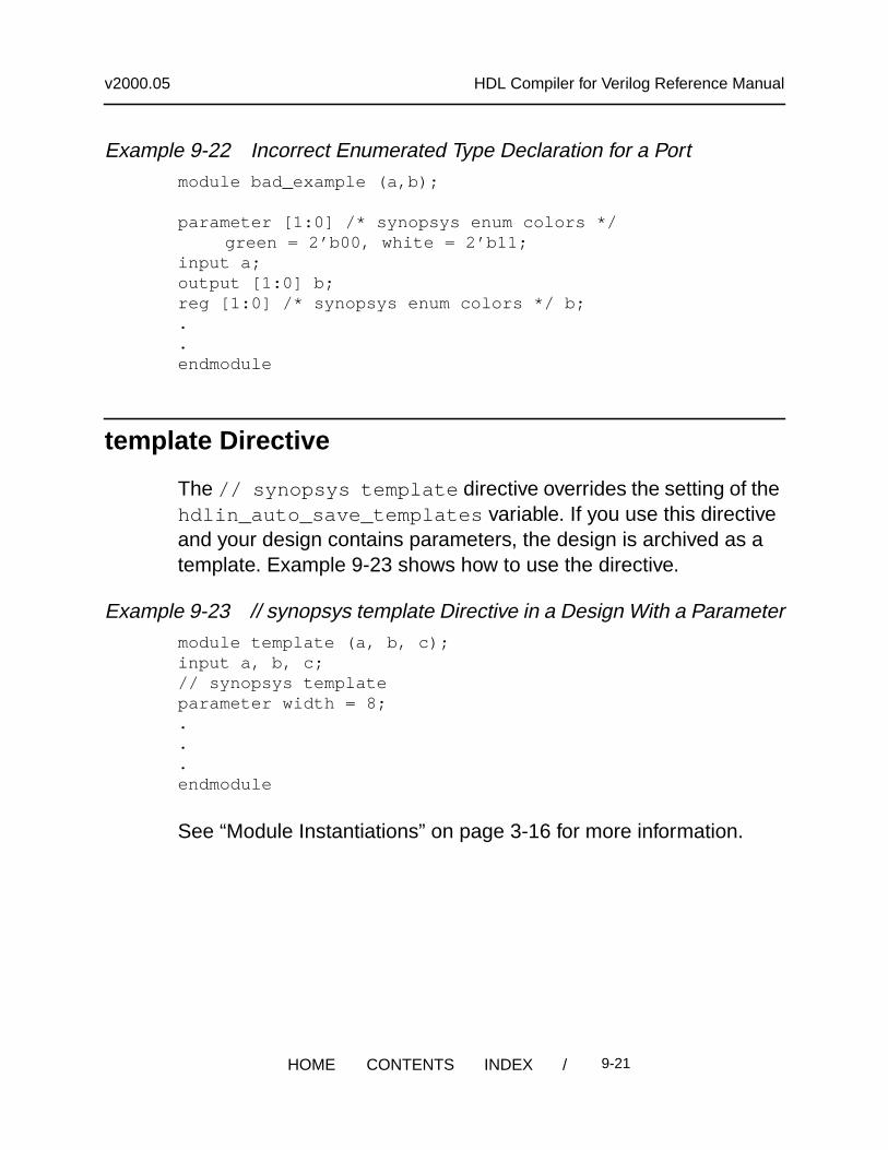
Example 9-22 shows the wrong way to declare a port as anenumerated type, because the enumerated type declarationappears with the reg declaration instead of with the output portdeclaration. This code does not export enumeration information toDesign Compiler.
/ 9-20HOME CONTENTS INDEX
v2000.05 HDL Compiler for Verilog Reference Manual
Example 9-22 Incorrect Enumerated Type Declaration for a Portmodule bad_example (a,b);
parameter [1:0] /* synopsys enum colors */green = 2’b00, white = 2’b11;
input a;output [1:0] b;reg [1:0] /* synopsys enum colors */ b;..endmodule
template Directive
The // synopsys template directive overrides the setting of thehdlin_auto_save_templates variable. If you use this directiveand your design contains parameters, the design is archived as atemplate. Example 9-23 shows how to use the directive.
Example 9-23 // synopsys template Directive in a Design With a Parametermodule template (a, b, c);input a, b, c;// synopsys templateparameter width = 8;...endmodule
See “Module Instantiations” on page 3-16 for more information.
/ 9-21HOME CONTENTS INDEX
v2000.05 HDL Compiler for Verilog Reference Manual
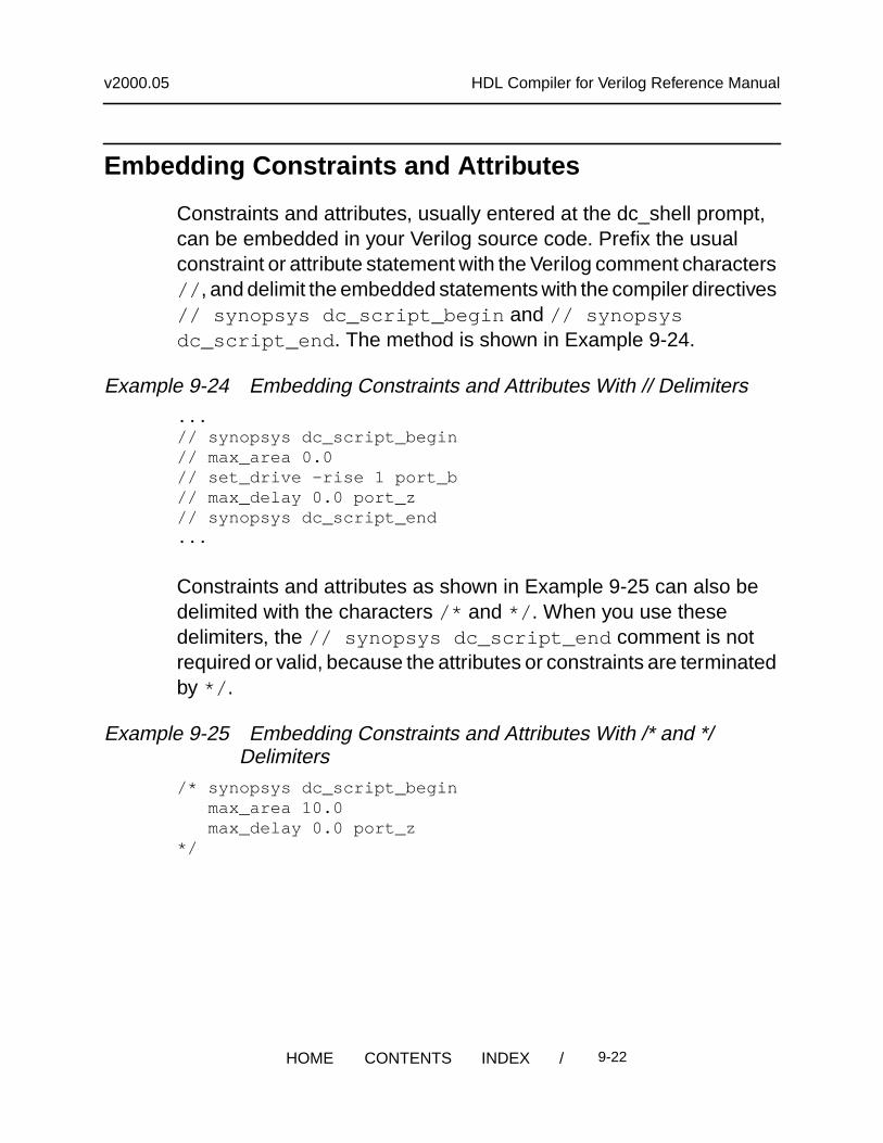
Embedding Constraints and Attributes
Constraints and attributes, usually entered at the dc_shell prompt,can be embedded in your Verilog source code. Prefix the usualconstraint or attribute statement with the Verilog comment characters// , and delimit the embedded statements with the compiler directives// synopsys dc_script_begin and // synopsysdc_script_end . The method is shown in Example 9-24.
Example 9-24 Embedding Constraints and Attributes With // Delimiters...// synopsys dc_script_begin// max_area 0.0// set_drive -rise 1 port_b// max_delay 0.0 port_z// synopsys dc_script_end...
Constraints and attributes as shown in Example 9-25 can also bedelimited with the characters /* and */ . When you use thesedelimiters, the // synopsys dc_script_end comment is notrequired or valid, because the attributes or constraints are terminatedby */ .
Example 9-25 Embedding Constraints and Attributes With /* and */Delimiters
/* synopsys dc_script_begin max_area 10.0 max_delay 0.0 port_z*/
/ 9-22HOME CONTENTS INDEX
v2000.05 HDL Compiler for Verilog Reference Manual
The dc_shell script interprets the statements embedded between the// synopsys dc_script_begin and the// synopsys dc_script_end directives. If you want to commentout part of your dc_shell script, use the convention for comments thatdc_shell uses.
Limitations on the Scope of Constraints and Attributes
The following limitations apply to the use of constraints and attributesin your design:
• Constraints and attributes declared outside a module apply to allsubsequent modules declared in the file.
• Constraints and attributes declared inside a module apply only tothe enclosing module.
• Any dc_shell scripts embedded in functions apply to the wholemodule.
• Include in your dc_shell script only commands that set constraintsand attributes. Do not use action commands such as compile ,gen , and report .
• The constraints or attributes set in the embedded script go intoeffect after the read command is executed. Therefore, variablesthat affect the read process itself are not in effect before the read.Thus, if you set the variable hdlin_no_latches = true in theembedded script, this variable does not influence latch inferencein the current read.
• dc_shell performs error checking after the read commandfinishes. Syntactic and semantic errors in dc_shell strings arereported at this time.
/ 9-23HOME CONTENTS INDEX
v2000.05 HDL Compiler for Verilog Reference Manual
Component Implication
In Verilog, you cannot instantiate modules in behavioral code. Toinclude an embedded netlist in your behavioral code, use thedirectives // synopsys map_to_module and// synopsys return_port_name for HDL Compiler to recognizethe netlist as a function being implemented by another module. Whenthis subprogram is invoked in the behavioral code, HDL Compilerinstantiates the module (see Example 9-26 on page 9-25).
The first directive, // synopsys map_to_module , flags a functionfor implementation as a distinct component. The syntax is
// synopsys map_to_module modulename
The second directive, // synopsys return_port_name ,identifies a return port (functions in Verilog do not have output ports).To instantiate the function as a component, the return port must havea name. The syntax is
// synopsys return_port_name portname
Note:Remember that if you add a map_to_module directive to afunction, the contents of the function are parsed and ignoredwhereas the indicated module is instantiated. Ensure that thefunctionality of the module instantiated in this way and the functionit replaces are the same; otherwise, pre-synthesis and post-synthesis simulation do not match.
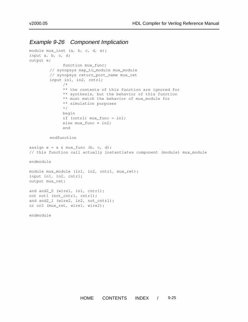
Example 9-26 illustrates the map_to_module andreturn_port_name directives.
/ 9-24HOME CONTENTS INDEX
v2000.05 HDL Compiler for Verilog Reference Manual
Example 9-26 Component Implicationmodule mux_inst (a, b, c, d, e);input a, b, c, d;output e;
function mux_func;// synopsys map_to_module mux_module// synopsys return_port_name mux_retinput in1, in2, cntrl;
/*** the contents of this function are ignored for** synthesis, but the behavior of this function** must match the behavior of mux_module for** simulation purposes*/beginif (cntrl) mux_func = in1;else mux_func = in2;end
endfunction
assign e = a & mux_func (b, c, d);// this function call actually instantiates component (module) mux_module
endmodule
module mux_module (in1, in2, cntrl, mux_ret);input in1, in2, cntrl;output mux_ret;
and and2_0 (wire1, in1, cntrl);not not1 (not_cntrl, cntrl);and and2_1 (wire2, in2, not_cntrl);or or2 (mux_ret, wire1, wire2);
endmodule
/ 9-25HOME CONTENTS INDEX
v2000.05 HDL Compiler for Verilog Reference Manual
/ 9-26HOME CONTENTS INDEX