Embed Size (px)
Citation preview
HDL Modeling for BuildGates SynthesisUser Guide
Product Version 5.0.13December 2003

2002-2003 Cadence Design Systems, Inc. All rights reserved.Printed in the United States of America.
Cadence Design Systems, Inc., 555 River Oaks Parkway, San Jose, CA 95134, USA
Trademarks: Trademarks and service marks of Cadence Design Systems, Inc. (Cadence) contained inthis document are attributed to Cadence with the appropriate symbol. For queries regarding Cadence’strademarks, contact the corporate legal department at the address shown above or call 1-800-862-4522.
All other trademarks are the property of their respective holders.
Restricted Print Permission: This publication is protected by copyright and any unauthorized use of thispublication may violate copyright, trademark, and other laws. Except as specified in this permissionstatement, this publication may not be copied, reproduced, modified, published, uploaded, posted,transmitted, or distributed in any way, without prior written permission from Cadence. This statement grantsyou permission to print one (1) hard copy of this publication subject to the following conditions:
1. The publication may be used solely for personal, informational, and noncommercial purposes;2. The publication may not be modified in any way;3. Any copy of the publication or portion thereof must include all original copyright, trademark, and other
proprietary notices and this permission statement; and4. Cadence reserves the right to revoke this authorization at any time, and any such use shall be
discontinued immediately upon written notice from Cadence.
Disclaimer: Information in this publication is subject to change without notice and does not represent acommitment on the part of Cadence. The information contained herein is the proprietary and confidentialinformation of Cadence or its licensors, and is supplied subject to, and may be used only by Cadence’scustomer in accordance with, a written agreement between Cadence and its customer. Except as may beexplicitly set forth in such agreement, Cadence does not make, and expressly disclaims, anyrepresentations or warranties as to the completeness, accuracy or usefulness of the information containedin this document. Cadence does not warrant that use of such information will not infringe any third partyrights, nor does Cadence assume any liability for damages or costs of any kind that may result from use ofsuch information.
Restricted Rights: Use, duplication, or disclosure by the Government is subject to restrictions as set forthin FAR52.227-14 and DFAR252.227-7013 et seq. or its successor.
HDL Modeling for BuildGates Synthesis
List of Examples . . . . . . . . . . . . . . . . . . . . . . . . . . . . . . . . . . . . . . . . . . . . . . . . . . . 9
List of Figures . . . . . . . . . . . . . . . . . . . . . . . . . . . . . . . . . . . . . . . . . . . . . . . . . . . . . 13
List of Tables . . . . . . . . . . . . . . . . . . . . . . . . . . . . . . . . . . . . . . . . . . . . . . . . . . . . . . 15
Preface . . . . . . . . . . . . . . . . . . . . . . . . . . . . . . . . . . . . . . . . . . . . . . . . . . . . . . . . . . . . . 17
About This Manual . . . . . . . . . . . . . . . . . . . . . . . . . . . . . . . . . . . . . . . . . . . . . . . . . . . . . . 18Other Information Sources . . . . . . . . . . . . . . . . . . . . . . . . . . . . . . . . . . . . . . . . . . . . . . . . 18Documentation Conventions . . . . . . . . . . . . . . . . . . . . . . . . . . . . . . . . . . . . . . . . . . . . . . 20
Using Menus . . . . . . . . . . . . . . . . . . . . . . . . . . . . . . . . . . . . . . . . . . . . . . . . . . . . . . . 20Using Forms . . . . . . . . . . . . . . . . . . . . . . . . . . . . . . . . . . . . . . . . . . . . . . . . . . . . . . . . 21
1Modeling and Synthesizing HDL Designs . . . . . . . . . . . . . . . . . . . . . 23
Overview . . . . . . . . . . . . . . . . . . . . . . . . . . . . . . . . . . . . . . . . . . . . . . . . . . . . . . . . . . . . . 24RTL Synthesis Flow . . . . . . . . . . . . . . . . . . . . . . . . . . . . . . . . . . . . . . . . . . . . . . . . . . 25
Tasks . . . . . . . . . . . . . . . . . . . . . . . . . . . . . . . . . . . . . . . . . . . . . . . . . . . . . . . . . . . . . . . . 26Read Design Data . . . . . . . . . . . . . . . . . . . . . . . . . . . . . . . . . . . . . . . . . . . . . . . . . . . 27Build Generic Design . . . . . . . . . . . . . . . . . . . . . . . . . . . . . . . . . . . . . . . . . . . . . . . . . 28Optimize Design . . . . . . . . . . . . . . . . . . . . . . . . . . . . . . . . . . . . . . . . . . . . . . . . . . . . . 29Report Resources . . . . . . . . . . . . . . . . . . . . . . . . . . . . . . . . . . . . . . . . . . . . . . . . . . . 29Write Netlist . . . . . . . . . . . . . . . . . . . . . . . . . . . . . . . . . . . . . . . . . . . . . . . . . . . . . . . . 30
Additional Information . . . . . . . . . . . . . . . . . . . . . . . . . . . . . . . . . . . . . . . . . . . . . . . . . . . 31Synthesizing Mixed VHDL and Verilog Designs . . . . . . . . . . . . . . . . . . . . . . . . . . . . . 32Querying the HDL Design Pool . . . . . . . . . . . . . . . . . . . . . . . . . . . . . . . . . . . . . . . . . 33Synthesizing a Specified Module . . . . . . . . . . . . . . . . . . . . . . . . . . . . . . . . . . . . . . . . 36Synthesizing Multiple Top-Level Designs . . . . . . . . . . . . . . . . . . . . . . . . . . . . . . . . . . 37Synthesizing Parameterized Designs . . . . . . . . . . . . . . . . . . . . . . . . . . . . . . . . . . . . . 38Synthesizing Designs with GTECH Cells . . . . . . . . . . . . . . . . . . . . . . . . . . . . . . . . . . 39
Troubleshooting . . . . . . . . . . . . . . . . . . . . . . . . . . . . . . . . . . . . . . . . . . . . . . . . . . . . . . . . 40
December 2003 3 Product Version 5.0.13
HDL Modeling for BuildGates Synthesis
2High-Level Optimizations . . . . . . . . . . . . . . . . . . . . . . . . . . . . . . . . . . . . . . . . 41
Overview . . . . . . . . . . . . . . . . . . . . . . . . . . . . . . . . . . . . . . . . . . . . . . . . . . . . . . . . . . . . . 42Tasks . . . . . . . . . . . . . . . . . . . . . . . . . . . . . . . . . . . . . . . . . . . . . . . . . . . . . . . . . . . . . . . . 44
Resource Sharing . . . . . . . . . . . . . . . . . . . . . . . . . . . . . . . . . . . . . . . . . . . . . . . . . . . . 45Tree Height Reduction (THR) . . . . . . . . . . . . . . . . . . . . . . . . . . . . . . . . . . . . . . . . . . . 46Implicit Constant Propagation (ICP) . . . . . . . . . . . . . . . . . . . . . . . . . . . . . . . . . . . . . . 50Common Sub-Expression Elimination (CSE) . . . . . . . . . . . . . . . . . . . . . . . . . . . . . . . 51Architecture Selection . . . . . . . . . . . . . . . . . . . . . . . . . . . . . . . . . . . . . . . . . . . . . . . . 53Extraction of Sum-of-Products (SOP) Logic . . . . . . . . . . . . . . . . . . . . . . . . . . . . . . . 54Multiplexer Optimization . . . . . . . . . . . . . . . . . . . . . . . . . . . . . . . . . . . . . . . . . . . . . . . 55Finite State Machine (FSM) Extraction . . . . . . . . . . . . . . . . . . . . . . . . . . . . . . . . . . . . 56
Additional Information . . . . . . . . . . . . . . . . . . . . . . . . . . . . . . . . . . . . . . . . . . . . . . . . . . . 57Sharing Hardware Resources . . . . . . . . . . . . . . . . . . . . . . . . . . . . . . . . . . . . . . . . . . 58Minimizing Implementation Area by Matching Bit Widths . . . . . . . . . . . . . . . . . . . . . . 59Minimizing MUX Overhead by Matching Common HDL Variables . . . . . . . . . . . . . . . 60Removing Redundant Multiplexers . . . . . . . . . . . . . . . . . . . . . . . . . . . . . . . . . . . . . . . 61Sharing Multi-Function Operations . . . . . . . . . . . . . . . . . . . . . . . . . . . . . . . . . . . . . . . 61Sharing Across Nested Conditions . . . . . . . . . . . . . . . . . . . . . . . . . . . . . . . . . . . . . . . 61Avoiding Combinational Loops . . . . . . . . . . . . . . . . . . . . . . . . . . . . . . . . . . . . . . . . . . 62Interacting with Other Optimization Techniques . . . . . . . . . . . . . . . . . . . . . . . . . . . . . 63
Troubleshooting . . . . . . . . . . . . . . . . . . . . . . . . . . . . . . . . . . . . . . . . . . . . . . . . . . . . . . . . 66
3Synthesizing Verilog Designs . . . . . . . . . . . . . . . . . . . . . . . . . . . . . . . . . . . 67
Overview . . . . . . . . . . . . . . . . . . . . . . . . . . . . . . . . . . . . . . . . . . . . . . . . . . . . . . . . . . . . . 68Tasks . . . . . . . . . . . . . . . . . . . . . . . . . . . . . . . . . . . . . . . . . . . . . . . . . . . . . . . . . . . . . . . . 69
Read Design Data . . . . . . . . . . . . . . . . . . . . . . . . . . . . . . . . . . . . . . . . . . . . . . . . . . . 69Build Generic Design . . . . . . . . . . . . . . . . . . . . . . . . . . . . . . . . . . . . . . . . . . . . . . . . . 72Write Netlist . . . . . . . . . . . . . . . . . . . . . . . . . . . . . . . . . . . . . . . . . . . . . . . . . . . . . . . . 72
Additional Information . . . . . . . . . . . . . . . . . . . . . . . . . . . . . . . . . . . . . . . . . . . . . . . . . . . 75Verilog Modeling Styles . . . . . . . . . . . . . . . . . . . . . . . . . . . . . . . . . . . . . . . . . . . . . . . 75Verilog Synthesis Directives . . . . . . . . . . . . . . . . . . . . . . . . . . . . . . . . . . . . . . . . . . . . 90
Verilog Compiler Directives . . . . . . . . . . . . . . . . . . . . . . . . . . . . . . . . . . . . . . . . . . . . . . 104
December 2003 4 Product Version 5.0.13
HDL Modeling for BuildGates Synthesis
Non-Standard Verilog Compiler Directives . . . . . . . . . . . . . . . . . . . . . . . . . . . . . . . . 104Supported Synopsys Directives . . . . . . . . . . . . . . . . . . . . . . . . . . . . . . . . . . . . . . . . 105Verilog-Related Commands and Globals . . . . . . . . . . . . . . . . . . . . . . . . . . . . . . . . . 106
Supported Verilog Modeling Constructs . . . . . . . . . . . . . . . . . . . . . . . . . . . . . . . . . . . . 108Troubleshooting . . . . . . . . . . . . . . . . . . . . . . . . . . . . . . . . . . . . . . . . . . . . . . . . . . . . . . . 117
do_build_generic Generates Extremely Long Module Name . . . . . . . . . . . . . . . . . . 118Eliminating Busses in a Netlist . . . . . . . . . . . . . . . . . . . . . . . . . . . . . . . . . . . . . . . . . 118Resolving Name Mapping Problem with Formal Verification . . . . . . . . . . . . . . . . . . 118Eliminating Unwanted Escape Characters in Front of Signal Names . . . . . . . . . . . . 120BuildGates Synthesis Does Not Prune Registers With Their D Inputs Constant . . . 120Preserving Instances from the RTL Through the Optimization Flow . . . . . . . . . . . . 121Preserving the set and reset Signals Next to the D-input of the Flip Flops . . . . . . . 122Preventing Modules from being Overwritten During read_verilog . . . . . . . . . . . 122Using the \ Character in Verilog . . . . . . . . . . . . . . . . . . . . . . . . . . . . . . . . . . . . . . . . 122Low Power Synthesis Cannot Apply Inferred Enable Register Banks . . . . . . . . . . . 123Honoring ‘defines in an ‘include File in a Verilog Pre-Processor . . . . . . . . . . 123Removing Bus Objects in the Hierarchy or Module . . . . . . . . . . . . . . . . . . . . . . . . . 124Generating Incorrect Logic for Asynchronous set and reset Pins . . . . . . . . . . . . . . 125Floating Nets . . . . . . . . . . . . . . . . . . . . . . . . . . . . . . . . . . . . . . . . . . . . . . . . . . . . . . 125
4Verilog-2001 Extensions . . . . . . . . . . . . . . . . . . . . . . . . . . . . . . . . . . . . . . . . 127
Overview . . . . . . . . . . . . . . . . . . . . . . . . . . . . . . . . . . . . . . . . . . . . . . . . . . . . . . . . . . . . 128Verilog-2001 Hardware Description Language Extensions . . . . . . . . . . . . . . . . . . . . . . 128
Verilog-1995, Verilog-2001, and Verilog Datapath Modes of Parsing . . . . . . . . . . . . 129Generate Statements . . . . . . . . . . . . . . . . . . . . . . . . . . . . . . . . . . . . . . . . . . . . . . . . 129Multidimensional Arrays . . . . . . . . . . . . . . . . . . . . . . . . . . . . . . . . . . . . . . . . . . . . . . 134Automatic Functions and Tasks . . . . . . . . . . . . . . . . . . . . . . . . . . . . . . . . . . . . . . . . 135Parameter Passing by Name . . . . . . . . . . . . . . . . . . . . . . . . . . . . . . . . . . . . . . . . . . 135Comma-Separated Sensitivity List . . . . . . . . . . . . . . . . . . . . . . . . . . . . . . . . . . . . . . 136ANSI-Style Declarations . . . . . . . . . . . . . . . . . . . . . . . . . . . . . . . . . . . . . . . . . . . . . . 136Variable Part Selects . . . . . . . . . . . . . . . . . . . . . . . . . . . . . . . . . . . . . . . . . . . . . . . . 137Constant Functions . . . . . . . . . . . . . . . . . . . . . . . . . . . . . . . . . . . . . . . . . . . . . . . . . 137New Preprocessor Directives . . . . . . . . . . . . . . . . . . . . . . . . . . . . . . . . . . . . . . . . . . 138
December 2003 5 Product Version 5.0.13
HDL Modeling for BuildGates Synthesis
5Synthesizing VHDL Designs . . . . . . . . . . . . . . . . . . . . . . . . . . . . . . . . . . . 141
Overview . . . . . . . . . . . . . . . . . . . . . . . . . . . . . . . . . . . . . . . . . . . . . . . . . . . . . . . . . . . . 142Tasks . . . . . . . . . . . . . . . . . . . . . . . . . . . . . . . . . . . . . . . . . . . . . . . . . . . . . . . . . . . . . . . 143
Setting the Globals for Synthesizing VHDL Designs . . . . . . . . . . . . . . . . . . . . . . . . 144Read Design Data . . . . . . . . . . . . . . . . . . . . . . . . . . . . . . . . . . . . . . . . . . . . . . . . . . 148Build Generic Design . . . . . . . . . . . . . . . . . . . . . . . . . . . . . . . . . . . . . . . . . . . . . . . . 155Write Netlist . . . . . . . . . . . . . . . . . . . . . . . . . . . . . . . . . . . . . . . . . . . . . . . . . . . . . . . 156
Additional Information . . . . . . . . . . . . . . . . . . . . . . . . . . . . . . . . . . . . . . . . . . . . . . . . . . 159Hierarchical VHDL Designs . . . . . . . . . . . . . . . . . . . . . . . . . . . . . . . . . . . . . . . . . . . 160VHDL Modeling Styles . . . . . . . . . . . . . . . . . . . . . . . . . . . . . . . . . . . . . . . . . . . . . . . 163VHDL Synthesis Directives . . . . . . . . . . . . . . . . . . . . . . . . . . . . . . . . . . . . . . . . . . . . 174Supported Synopsys Directives . . . . . . . . . . . . . . . . . . . . . . . . . . . . . . . . . . . . . . . . 191Supported Cadence (Ambit) Directives and BuildGates Equivalents . . . . . . . . . . . . 193Supported BuildGates Synthesis-Only VHDL Directives . . . . . . . . . . . . . . . . . . . . . 194VHDL-Related Commands and Globals . . . . . . . . . . . . . . . . . . . . . . . . . . . . . . . . . . 196VHDL Constructs . . . . . . . . . . . . . . . . . . . . . . . . . . . . . . . . . . . . . . . . . . . . . . . . . . . 199
Troubleshooting . . . . . . . . . . . . . . . . . . . . . . . . . . . . . . . . . . . . . . . . . . . . . . . . . . . . . . . 210VHDL Netlist from write_vhdl Missing Generic Delay Parameters . . . . . . . . . . . 211Cannot Infer a Bus Keeper Element Using a BLOCK/GUARDED Statement . . . . . 211Extra Generic Logic Added to VHDL Netlist with Undriven Nets . . . . . . . . . . . . . . . 211Undriven Ports and Nets Left After Optimization . . . . . . . . . . . . . . . . . . . . . . . . . . . 211Error When Using IEEE Standard Logic Packages in BuildGates . . . . . . . . . . . . . . 212Unconnected Flip Flops in the Final Netlist . . . . . . . . . . . . . . . . . . . . . . . . . . . . . . . 212Setting Finite State Machine Compile Directives for a VHDL Finite State . . . . . . . . 213Error During do_build_generic if Design Architecture is not Specified . . . . . . . 214Unconditional Loops are not Supported if There is More than One Clock Edge . . . 214Error on the Condition Clause of a wait Using read_vhdl . . . . . . . . . . . . . . . . . . 215VHDL LOOP Construct Runs Out of Memory . . . . . . . . . . . . . . . . . . . . . . . . . . . . . 216Undeclared Identifier Error Message in VHDL Structural Netlists . . . . . . . . . . . . . . 217Locally Static Expressions in VHDL87 LRM and VHDL93 LRM . . . . . . . . . . . . . . . 218VHDL93 LRM Definition of a Locally Static Expression . . . . . . . . . . . . . . . . . . . . . . 218Using the \ Character in VHDL . . . . . . . . . . . . . . . . . . . . . . . . . . . . . . . . . . . . . . . . . 218Passing Generic Values from the Command Line . . . . . . . . . . . . . . . . . . . . . . . . . . 219Writing One-Bit Busses . . . . . . . . . . . . . . . . . . . . . . . . . . . . . . . . . . . . . . . . . . . . . . 219
December 2003 6 Product Version 5.0.13
HDL Modeling for BuildGates Synthesis
6Optimizing and Structuring Finite State Machines. . . . . . . . . . . 221
Overview . . . . . . . . . . . . . . . . . . . . . . . . . . . . . . . . . . . . . . . . . . . . . . . . . . . . . . . . . . . . 222Tasks . . . . . . . . . . . . . . . . . . . . . . . . . . . . . . . . . . . . . . . . . . . . . . . . . . . . . . . . . . . . . . . 225
Model FSM . . . . . . . . . . . . . . . . . . . . . . . . . . . . . . . . . . . . . . . . . . . . . . . . . . . . . . . . 225Synthesize FSM . . . . . . . . . . . . . . . . . . . . . . . . . . . . . . . . . . . . . . . . . . . . . . . . . . . . 225
Additional Information . . . . . . . . . . . . . . . . . . . . . . . . . . . . . . . . . . . . . . . . . . . . . . . . . . 228state_vector Directive . . . . . . . . . . . . . . . . . . . . . . . . . . . . . . . . . . . . . . . . . . . . . . . . 228FSM Coding Styles . . . . . . . . . . . . . . . . . . . . . . . . . . . . . . . . . . . . . . . . . . . . . . . . . . 230FSM Verification . . . . . . . . . . . . . . . . . . . . . . . . . . . . . . . . . . . . . . . . . . . . . . . . . . . . 237
Troubleshooting . . . . . . . . . . . . . . . . . . . . . . . . . . . . . . . . . . . . . . . . . . . . . . . . . . . . . . . 243Mux Inference Pragma is not Honored in a Finite State Machine . . . . . . . . . . . . . . 244A 3 state FSM Causes do_build_generic to Crash when extract_fsm is On 244Setting FSM Compile Directives for a VHDL Finite State . . . . . . . . . . . . . . . . . . . . . 244State Machine Extraction Fails, by either Hanging or Running Out of Memory . . . . 245Coding State Machines in VHDL . . . . . . . . . . . . . . . . . . . . . . . . . . . . . . . . . . . . . . . 245FSM Extraction Fails in the Presence of Incompletely Assigned Registers . . . . . . . 246
7Using the EDIF Interface. . . . . . . . . . . . . . . . . . . . . . . . . . . . . . . . . . . . . . . . 251
Overview . . . . . . . . . . . . . . . . . . . . . . . . . . . . . . . . . . . . . . . . . . . . . . . . . . . . . . . . . . . . 252Tasks . . . . . . . . . . . . . . . . . . . . . . . . . . . . . . . . . . . . . . . . . . . . . . . . . . . . . . . . . . . . . . . 252
Read Design Data . . . . . . . . . . . . . . . . . . . . . . . . . . . . . . . . . . . . . . . . . . . . . . . . . . 253Write Netlist . . . . . . . . . . . . . . . . . . . . . . . . . . . . . . . . . . . . . . . . . . . . . . . . . . . . . . . 254Represent Power and Ground in EDIF . . . . . . . . . . . . . . . . . . . . . . . . . . . . . . . . . . . 254
Troubleshooting . . . . . . . . . . . . . . . . . . . . . . . . . . . . . . . . . . . . . . . . . . . . . . . . . . . . . . . 263How to Export an EDIF Schematic for Viewing in a Different Tool . . . . . . . . . . . . . . 263
AAmbitWare . . . . . . . . . . . . . . . . . . . . . . . . . . . . . . . . . . . . . . . . . . . . . . . . . . . . . . . . 265
Introduction . . . . . . . . . . . . . . . . . . . . . . . . . . . . . . . . . . . . . . . . . . . . . . . . . . . . . . . . . . 266Generators . . . . . . . . . . . . . . . . . . . . . . . . . . . . . . . . . . . . . . . . . . . . . . . . . . . . . . . . 266Libraries . . . . . . . . . . . . . . . . . . . . . . . . . . . . . . . . . . . . . . . . . . . . . . . . . . . . . . . . . . 267
AmbitWare Flow . . . . . . . . . . . . . . . . . . . . . . . . . . . . . . . . . . . . . . . . . . . . . . . . . . . . . . . 268
December 2003 7 Product Version 5.0.13
HDL Modeling for BuildGates Synthesis
AmbitWare Generators . . . . . . . . . . . . . . . . . . . . . . . . . . . . . . . . . . . . . . . . . . . . . . . . . 269AWACL Generator . . . . . . . . . . . . . . . . . . . . . . . . . . . . . . . . . . . . . . . . . . . . . . . . . . 270AWDP Generator . . . . . . . . . . . . . . . . . . . . . . . . . . . . . . . . . . . . . . . . . . . . . . . . . . . 271AWMUX Generator . . . . . . . . . . . . . . . . . . . . . . . . . . . . . . . . . . . . . . . . . . . . . . . . . . 273AWSOP Generator . . . . . . . . . . . . . . . . . . . . . . . . . . . . . . . . . . . . . . . . . . . . . . . . . . 274AWRS Generator . . . . . . . . . . . . . . . . . . . . . . . . . . . . . . . . . . . . . . . . . . . . . . . . . . . 275
AmbitWare Libraries . . . . . . . . . . . . . . . . . . . . . . . . . . . . . . . . . . . . . . . . . . . . . . . . . . . 276Setting the Library Search Order . . . . . . . . . . . . . . . . . . . . . . . . . . . . . . . . . . . . . . . 277Using Predefined AmbitWare Libraries . . . . . . . . . . . . . . . . . . . . . . . . . . . . . . . . . . 277Defining Your Own AmbitWare Libraries . . . . . . . . . . . . . . . . . . . . . . . . . . . . . . . . . 277Using Synthesis Directives . . . . . . . . . . . . . . . . . . . . . . . . . . . . . . . . . . . . . . . . . . . . 282
BFunctional Verification with Verplex . . . . . . . . . . . . . . . . . . . . . . . . . . . 283
Introduction . . . . . . . . . . . . . . . . . . . . . . . . . . . . . . . . . . . . . . . . . . . . . . . . . . . . . . . . . . 284Verplex Conformal Logical Equivalence Checker . . . . . . . . . . . . . . . . . . . . . . . . . . . . . 284
Non-Equivalency Resolutions . . . . . . . . . . . . . . . . . . . . . . . . . . . . . . . . . . . . . . . . . . 284
Index. . . . . . . . . . . . . . . . . . . . . . . . . . . . . . . . . . . . . . . . . . . . . . . . . . . . . . . . . . . . . . . 289
December 2003 8 Product Version 5.0.13

HDL Modeling for BuildGates Synthesis
List of Examples
Example 1-1 Instantiating a Counter in a VHDL Module . . . . . . . . . . . . . . . . . . . . . . . . . . 32
Example 1-2 Instantiating a Counter in a Verilog Module. . . . . . . . . . . . . . . . . . . . . . . . . . 32
Example 1-3 VHDL Design Consisting of Three Entities . . . . . . . . . . . . . . . . . . . . . . . . . . 34
Example 1-4 Using the -module Option for Each of the Top-Level Designs . . . . . . . . . . . . 37
Example 1-5 Using the -all Option . . . . . . . . . . . . . . . . . . . . . . . . . . . . . . . . . . . . . . . . . . . 37
Example 1-6 Using the foreach TCL Command. . . . . . . . . . . . . . . . . . . . . . . . . . . . . . . . . 37
Example 1-7 Automatic Elaboration . . . . . . . . . . . . . . . . . . . . . . . . . . . . . . . . . . . . . . . . . . 38
Example 1-8 Overriding the Default Parameter Values . . . . . . . . . . . . . . . . . . . . . . . . . . . 40
Example 2-1 THR Produces Better Slack and Area. . . . . . . . . . . . . . . . . . . . . . . . . . . . . . 46
Example 2-2 Modeling Bit-Width Matching. . . . . . . . . . . . . . . . . . . . . . . . . . . . . . . . . . . . . 47
Example 2-3 Modeling Parentheses with Tree Height Reduction. . . . . . . . . . . . . . . . . . . . 48
Example 2-4 Applying ICP to an if Statement . . . . . . . . . . . . . . . . . . . . . . . . . . . . . . . . . 50
Example 2-5 RTL Description with a Redundant Arithmetic Expression . . . . . . . . . . . . . . 51
Example 2-1 Operator Merging . . . . . . . . . . . . . . . . . . . . . . . . . . . . . . . . . . . . . . . . . . . . . 63
Example 3-1 Modeling an Asynchronous Operation On a Flip-Flop . . . . . . . . . . . . . . . . . 81
Example 3-2 Negating the Condition in an if Statement. . . . . . . . . . . . . . . . . . . . . . . . . . . 82
Example 3-3 Modeling a State Transition Table to Infer a Latch. . . . . . . . . . . . . . . . . . . . . 84
Example 3-4 Preventing a Latch by Assigning a Default Value to next_state . . . . . . . . 84
Example 3-5 Preventing a Latch by Using the Default case in the case Statement . . . . . 85
Example 3-6 Using Don’t Care Conditions in a casez Statement . . . . . . . . . . . . . . . . . . . 86
Example 3-7 Report of the casex Statement . . . . . . . . . . . . . . . . . . . . . . . . . . . . . . . . . . . 87
Example 3-8 Using Don’t Care Conditions in a casex Statement . . . . . . . . . . . . . . . . . . . 88
Example 3-9 Report of the casex Statement . . . . . . . . . . . . . . . . . . . . . . . . . . . . . . . . . . . 88
Example 3-10 Using the for Statement to Describe Repetitive Operations . . . . . . . . . . . . 89
Example 3-11 Using Synthesis On and Off Directives . . . . . . . . . . . . . . . . . . . . . . . . . . . . 91
Example 3-12 Specifying the Architecture Selection Directive . . . . . . . . . . . . . . . . . . . . . . 92
Example 3-13 Specifying the Architecture Selection Directive with Multiple Operators . . . 93
Example 3-14 Using the case Statement Directive . . . . . . . . . . . . . . . . . . . . . . . . . . . . . . 93
December 2003 9 Product Version 5.0.13

HDL Modeling for BuildGates Synthesis
Example 3-15 Using the full Case Directive to Suppress the Latch Inference . . . . . . . . 94
Example 3-16 Using the full Case Directive to Infer a Latch . . . . . . . . . . . . . . . . . . . . . 94
Example 3-17 Using the parallel Case Directive. . . . . . . . . . . . . . . . . . . . . . . . . . . . . . 95
Example 3-18 Using the Multiplexer case Directive . . . . . . . . . . . . . . . . . . . . . . . . . . . . . . 96
Example 3-19 Using the Module Template Directive . . . . . . . . . . . . . . . . . . . . . . . . . . . . . 96
Example 3-20 Using the map_to_module Directive . . . . . . . . . . . . . . . . . . . . . . . . . . . . . 97
Example 3-21 Using the return_port_name with the map_to_module Directive . . . . 97
Example 3-22 Implementing asynchronous set and reset Control Logic . . . . . . . . . . . . . . 99
Example 3-23 Using the set and reset Synchronous Signals Synthesis Directive . . . . . . 101
Example 3-24 Using the set_reset Synchronous Signals in a Block Synthesis Directive. 103
Example 3-25 Using the Operator Merging Directive . . . . . . . . . . . . . . . . . . . . . . . . . . . . 103
Example 3-26 Bitwise Assignment Restriction . . . . . . . . . . . . . . . . . . . . . . . . . . . . . . . . . 115
Example 3-27 Conditional Assignment Restriction. . . . . . . . . . . . . . . . . . . . . . . . . . . . . . 116
Example 3-28 Changing Module Names . . . . . . . . . . . . . . . . . . . . . . . . . . . . . . . . . . . . . 118
Example 3-29 Resolving Name Mapping Problem with Formal Verification. . . . . . . . . . . 118
Example 3-30 Preserving Inverters Without Using HDL Directives . . . . . . . . . . . . . . . . . 121
Example 3-31 Using Incorrect set and reset Logic . . . . . . . . . . . . . . . . . . . . . . . . . . . 125
Example 3-32 Using Correct set and reset Logic. . . . . . . . . . . . . . . . . . . . . . . . . . . . . 125
Example 4-1 Using the if generate Statement . . . . . . . . . . . . . . . . . . . . . . . . . . . . . . 130
Example 4-2 Using the if generate Statement . . . . . . . . . . . . . . . . . . . . . . . . . . . . . . 131
Example 4-3 Using the case generate Statement for Multi-Way Branching . . . . . . . . 131
Example 4-4 Using the case generate Statement to Define Primitives. . . . . . . . . . . . 132
Example 4-5 Using the for generate Statement . . . . . . . . . . . . . . . . . . . . . . . . . . . . . 133
Example 4-6 Using the for generate Statement . . . . . . . . . . . . . . . . . . . . . . . . . . . . . 134
Example 4-7 Examples of Multi-Dimensional Arrays of wire and reg . . . . . . . . . . . . . . 134
Example 4-8 Specifying Module Instance Parameters by Name . . . . . . . . . . . . . . . . . . . 135
Example 4-9 Using the defparam Keyword . . . . . . . . . . . . . . . . . . . . . . . . . . . . . . . . . . . 135
Example 4-10 Using a Comma-Separated Sensitivity List . . . . . . . . . . . . . . . . . . . . . . . . 136
Example 4-11 Verilog-1995 Style Declaration . . . . . . . . . . . . . . . . . . . . . . . . . . . . . . . . . 136
Example 4-12 Verilog-2001 ANSI C-like Declaration . . . . . . . . . . . . . . . . . . . . . . . . . . . . 136
Example 4-13 Variable Part Select . . . . . . . . . . . . . . . . . . . . . . . . . . . . . . . . . . . . . . . . . . 137
December 2003 10 Product Version 5.0.13
HDL Modeling for BuildGates Synthesis
Example 4-14 Using a Function Call in a Constant Expression . . . . . . . . . . . . . . . . . . . . 138
Example 4-15 Using the `ifndef Directive . . . . . . . . . . . . . . . . . . . . . . . . . . . . . . . . . . 139
Example 5-1 Report of Reusing HDL VHDL Units . . . . . . . . . . . . . . . . . . . . . . . . . . . . . . 152
Example 5-2 Instantiating an Entity for Synthesis . . . . . . . . . . . . . . . . . . . . . . . . . . . . . . 161
Example 5-3 Non-Synthesizable Design . . . . . . . . . . . . . . . . . . . . . . . . . . . . . . . . . . . . . 162
Example 5-4 Design with Restrictions on Entities with Multiple Architectures . . . . . . . . . 163
Example 5-5 Synthesizing Combinational Logic to Generate Signal z. . . . . . . . . . . . . . . 164
Example 5-6 Synthesizing Combinational Logic to Generate Signal z. . . . . . . . . . . . . . . 165
Example 5-7 Inferring a Latch . . . . . . . . . . . . . . . . . . . . . . . . . . . . . . . . . . . . . . . . . . . . . 166
Example 5-8 Inferring a Flip-Flop . . . . . . . . . . . . . . . . . . . . . . . . . . . . . . . . . . . . . . . . . . . 167
Example 5-9 Synthesizing a Synchronous set and reset Signals On a Flip-Flop . . . . 168
Example 5-10 Synthesizing Asynchronous set and reset Signals On a Flip-Flop . . . . 168
Example 5-11 Modeling a State Transition Table to Infer a Latch. . . . . . . . . . . . . . . . . . . 171
Example 5-12 Assigning the next_state Signal a Value Unconditionally, then Modifying itby a case Statement . . . . . . . . . . . . . . . . . . . . . . . . . . . . . . . . . . . . . . . . . . . . . . . . . . . . 172
Example 5-13 Using the others Clause in the case Statement to Capture all the RemainingCases where next_state is Assigned a Value . . . . . . . . . . . . . . . . . . . . . . . . . . . . . . . 172
Example 5-14 Using a for loop Statement to Describe Repetitive Operations . . . . . . . 173
Example 5-15 Reversing and Assigning Bits of curr_state to next_state. . . . . . . . 173
Example 5-16 Using Synthesis On and Off Directives . . . . . . . . . . . . . . . . . . . . . . . . . . . 175
Example 5-17 Using the Architecture Selection Directive for VHDL. . . . . . . . . . . . . . . . . 176
Example 5-18 Using the Architecture Selection Directive for Multiple Operators . . . . . . . 177
Example 5-19 Using the case Statement Directive . . . . . . . . . . . . . . . . . . . . . . . . . . . . . 177
Example 5-20 Using the Enumeration Encoding Directive . . . . . . . . . . . . . . . . . . . . . . . . 178
Example 5-21 Using the Entity Template Directive. . . . . . . . . . . . . . . . . . . . . . . . . . . . . . 178
Example 5-22 Using the Function and Task Mapping Directives . . . . . . . . . . . . . . . . . . . 179
Example 5-23 Using the Signed Type Directive . . . . . . . . . . . . . . . . . . . . . . . . . . . . . . . . 179
Example 5-24 Using the Resolution Function Directive . . . . . . . . . . . . . . . . . . . . . . . . . . 180
Example 5-25 Using the Type Conversion Directives . . . . . . . . . . . . . . . . . . . . . . . . . . . . 181
Example 5-26 Using the SYNC_SET_RESET_PROCESS Synthesis Directive . . . . . . . . . . 184
Example 5-27 Using the Signal Directive . . . . . . . . . . . . . . . . . . . . . . . . . . . . . . . . . . . . . 187
December 2003 11 Product Version 5.0.13
HDL Modeling for BuildGates Synthesis
Example 5-28 Using the SYNC_SET_RESET_LOCAL Synthesis Directive . . . . . . . . . . . . 189
Example 5-29 Using the Operator Merging Directive . . . . . . . . . . . . . . . . . . . . . . . . . . . . 190
Example 5-1 Using a VHDL87 LRM Range Expression that is Locally Static . . . . . . . . . 218
Example 6-1 Modeling a State Machine. . . . . . . . . . . . . . . . . . . . . . . . . . . . . . . . . . . . . . 223
Example 6-2 Using the VHDL state_vector Directive . . . . . . . . . . . . . . . . . . . . . . . . . . . . 229
Example 6-3 How Output Initialization is Lost . . . . . . . . . . . . . . . . . . . . . . . . . . . . . . . . . 232
Example 6-4 Compact Coding Style. . . . . . . . . . . . . . . . . . . . . . . . . . . . . . . . . . . . . . . . . 234
Example 6-5 Detailed Coding Style . . . . . . . . . . . . . . . . . . . . . . . . . . . . . . . . . . . . . . . . . 235
Example 6-6 Output Not Specified Completely . . . . . . . . . . . . . . . . . . . . . . . . . . . . . . . . 236
Example 6-7 Equivalence Checking Fails to Verify the Synthesized FSM, Whereas a Simula-tor Succeeds. . . . . . . . . . . . . . . . . . . . . . . . . . . . . . . . . . . . . . . . . . . . . . . . . . . . . . . . . . . 239
Example 6-8 Ambit Library and Attributes Package . . . . . . . . . . . . . . . . . . . . . . . . . . . . . 245
Example 6-9 FSM extraction fails due to incompletely assigned "burst_counter" . . . . . . 246
Example 6-10 FSM is extracted when "burst_counter" is completely assigned . . . . . . . . 248
Example 7-1 Verilog Model Showing How to Use the Power Net Globals . . . . . . . . . . . . 256
Example 7-2 Output for Module Bottom Using the Power Net Globals . . . . . . . . . . . . . . 256
Example 7-3 Output for EDIF Using Port Power and Ground Globals . . . . . . . . . . . . . . . 258
Example 7-4 Edif Output Using Power and Ground Globals . . . . . . . . . . . . . . . . . . . . . . 260
December 2003 12 Product Version 5.0.13

HDL Modeling for BuildGates Synthesis
List of Figures
Figure 1-1 RTL Synthesis Flow . . . . . . . . . . . . . . . . . . . . . . . . . . . . . . . . . . . . . . . . . . . . . 26
Figure 1-2 Schematic of VHDL Design with Three Entities . . . . . . . . . . . . . . . . . . . . . . . . 35
Figure 2-1 RTL Synthesis Flow-High-Level Optimizations . . . . . . . . . . . . . . . . . . . . . . . . . 43
Figure 2-2 Matching Bit-Widths with THR Disabled . . . . . . . . . . . . . . . . . . . . . . . . . . . . . . 47
Figure 2-3 Matching Bit-Widths with THR Enabled . . . . . . . . . . . . . . . . . . . . . . . . . . . . . . 48
Figure 2-4 Using Parenthesis with Tree Height Reduction Disabled . . . . . . . . . . . . . . . . . 49
Figure 2-5 Using Parenthesis with Tree Height Reduction Enabled . . . . . . . . . . . . . . . . . . 49
Figure 2-6 Generic Netlist Using Common Sub-Expression Elimination . . . . . . . . . . . . . . 52
Figure 2-7 Generic Netlist with Common Sub-Expression Elimination Disabled . . . . . . . . 52
Figure 2-8 Extracting Sum-of-Products Logic from a Constant case Statement . . . . . . . . 54
Figure 2-9 Modeling Two Arithmetic Expressions for Sharing . . . . . . . . . . . . . . . . . . . . . . 59
Figure 2-10 Matching Bit Widths . . . . . . . . . . . . . . . . . . . . . . . . . . . . . . . . . . . . . . . . . . . . 60
Figure 2-11 Matching Common HDL Variables . . . . . . . . . . . . . . . . . . . . . . . . . . . . . . . . . 60
Figure 2-12 Removing Redundant Multiplexers . . . . . . . . . . . . . . . . . . . . . . . . . . . . . . . . . 61
Figure 2-13 Sharing Across Conditional Statements . . . . . . . . . . . . . . . . . . . . . . . . . . . . . 62
Figure 2-14 Avoiding a Combinational Loop. . . . . . . . . . . . . . . . . . . . . . . . . . . . . . . . . . . . 62
Figure 2-15 Sharing Partial Arithmetic Expressions . . . . . . . . . . . . . . . . . . . . . . . . . . . . . . 64
Figure 3-1 RTL Synthesis Flow - Verilog . . . . . . . . . . . . . . . . . . . . . . . . . . . . . . . . . . . . . . 68
Figure 3-2 Synthesizing Combinational Logic to Implement Variable dout . . . . . . . . . . . . 76
Figure 3-3 Synthesizing Combinational Logic to Implement Signal z. . . . . . . . . . . . . . . . . 77
Figure 3-4 Inferring a Latch . . . . . . . . . . . . . . . . . . . . . . . . . . . . . . . . . . . . . . . . . . . . . . . . 79
Figure 3-5 Inferring a Flip-Flop . . . . . . . . . . . . . . . . . . . . . . . . . . . . . . . . . . . . . . . . . . . . . . 80
Figure 3-6 Schematic Representation of an Asynchronous Operation On a Flip-Flop. . . . 81
Figure 3-7 Schematic Representation of Negating the Condition in an if Statement . . . . . 83
Figure 3-8 Schematic Representation of Using Don’t Care Conditions in a casez Statement87
Figure 3-9 Schematic of set and reset Control Logic . . . . . . . . . . . . . . . . . . . . . . . . . . . . . 99
Figure 3-10 Schematic of set and reset Synchronous Signal Logic . . . . . . . . . . . . . . . . . 102
December 2003 13 Product Version 5.0.13
HDL Modeling for BuildGates Synthesis
Figure 5-1 RTL Synthesis Flow - VHDL . . . . . . . . . . . . . . . . . . . . . . . . . . . . . . . . . . . . . . 143
Figure 5-2 Default Implementation of set and reset Control Logic . . . . . . . . . . . . . . . . 182
Figure 5-3 Implementing set and reset Control Logic . . . . . . . . . . . . . . . . . . . . . . . . . 182
Figure 5-4 Implementing set and reset Synchronous Block Logic . . . . . . . . . . . . . . . . 185
Figure 5-5 Implementing set and reset Synchronous Signal Logic . . . . . . . . . . . . . . . 188
Figure 5-6 Implementing set and reset Synchronous Signals in a Block Logic . . . . . . 190
Figure 6-1 State Machine Structure—Two Case Statements . . . . . . . . . . . . . . . . . . . . . . 222
Figure 6-2 Rtl Synthesis Flow - FSM . . . . . . . . . . . . . . . . . . . . . . . . . . . . . . . . . . . . . . . . 224
Figure 7-1 RTL Synthesis Flow - EDIF . . . . . . . . . . . . . . . . . . . . . . . . . . . . . . . . . . . . . . . 252
Figure A-1 AmbitWare Flow in the RTL Flow . . . . . . . . . . . . . . . . . . . . . . . . . . . . . . . . . . 268
Figure A-2 Example Library Report . . . . . . . . . . . . . . . . . . . . . . . . . . . . . . . . . . . . . . . . . 282
December 2003 14 Product Version 5.0.13

HDL Modeling for BuildGates Synthesis
List of Tables
Table 2-1 Supported Adder Architectures. . . . . . . . . . . . . . . . . . . . . . . . . . . . . . . . . . . . . . 53
Table 3-1 Register Inference: set and reset Control . . . . . . . . . . . . . . . . . . . . . . . . . . . . . . 98
Table 3-2 Supported Verilog Synopsys Directives . . . . . . . . . . . . . . . . . . . . . . . . . . . . . . 105
Table 3-3 Verilog Related Commands . . . . . . . . . . . . . . . . . . . . . . . . . . . . . . . . . . . . . . . 106
Table 3-4 Verilog-Specific Global Variables . . . . . . . . . . . . . . . . . . . . . . . . . . . . . . . . . . . 106
Table 3-5 Verilog Constructs and Level of Support. . . . . . . . . . . . . . . . . . . . . . . . . . . . . . 108
Table 5-1 Predefined VHDL Environments . . . . . . . . . . . . . . . . . . . . . . . . . . . . . . . . . . . . 144
Table 5-2 Predefined VHDL Libraries Standard Environment . . . . . . . . . . . . . . . . . . . . . 145
Table 5-3 Predefined VHDL Libraries Synopsys Environment . . . . . . . . . . . . . . . . . . . . . 145
Table 5-4 Predefined VHDL Libraries Synergy Environment . . . . . . . . . . . . . . . . . . . . . . 145
Table 5-5 Predefined VHDL Libraries Common Environment . . . . . . . . . . . . . . . . . . . . . 146
Table 5-6 Supported VHDL Synopsys Directives . . . . . . . . . . . . . . . . . . . . . . . . . . . . . . . 191
Table 5-7 Supported Cadence (Ambit) VHDL Directives and BuildGates Equivalents. . . 193
Table 5-8 BuildGates-Only VHDL Directives . . . . . . . . . . . . . . . . . . . . . . . . . . . . . . . . . . 194
Table 5-9 VHDL shell Commands . . . . . . . . . . . . . . . . . . . . . . . . . . . . . . . . . . . . . . . . . 196
Table 5-10 VHDL-Specific Global Variables . . . . . . . . . . . . . . . . . . . . . . . . . . . . . . . . . . . 197
Table 5-11 VHDL Constructs Supported in BuildGates Synthesis . . . . . . . . . . . . . . . . . . 199
Table 5-12 Attribute Set for the Pre-defined Language Environment . . . . . . . . . . . . . . . . 208
Table 6-1 state_vector Encoding Options . . . . . . . . . . . . . . . . . . . . . . . . . . . . . . . . 226
Table 7-1 Globals for Specifying Power and Ground for Nets. . . . . . . . . . . . . . . . . . . . . . 255
Table 7-2 Globals for Representing Power and Ground for Ports. . . . . . . . . . . . . . . . . . . 257
Table 7-3 EDIF Globals for Specifying an Instance . . . . . . . . . . . . . . . . . . . . . . . . . . . . . 259
Table A-1 AmbitWare Generators and Libraries in BuildGates. . . . . . . . . . . . . . . . . . . . . 267
Table A-2 Library of Complete ATL and XATL Multiplexers . . . . . . . . . . . . . . . . . . . . . . . 273
December 2003 15 Product Version 5.0.13

HDL Modeling for BuildGates Synthesis
December 2003 16 Product Version 5.0.13
HDL Modeling for BuildGates Synthesis
Preface
This preface contains the following sections:
■ About This Manual on page 18
■ Other Information Sources on page 18
■ Documentation Conventions on page 20
December 2003 17 Product Version 5.0.13
HDL Modeling for BuildGates SynthesisPreface
About This Manual
This manual describes HDL modeling for BuildGates Synthesis. The BuildGates® synthesissoftware accepts both VHDL and Verilog design modules.
Other Information Sources
For more information about BuildGates Synthesis and other related products, consult thefollowing sources:
■ AmbitWare Component Reference
■ BuildGates Synthesis User Guide
■ CeltIC User Guide
■ Command Reference for BuildGates Synthesis and Cadence PKS
■ Datapath for BuildGates Synthesis and Cadence PKS
■ Delay Calculation Algorithm Guide
■ Design for Test Using BuildGates Synthesis and Cadence PKS
■ Distributed Processing for BuildGates Synthesis
■ Global Variable Reference for BuildGates Synthesis and Cadence PKS
■ Glossary for BuildGates Synthesis and Cadence PKS
■ GUI Guide for BuildGates Synthesis and Cadence PKS
■ Low Power for BuildGates Synthesis and Cadence PKS
■ Low Power Synthesis Tutorial
■ Migration Guide for BuildGates Synthesis and Cadence PKS
■ Modeling Generation for Verilog 2001 and the Verilog Datapath Extension
■ PKS User Guide
■ SDC Constraints Support Guide
■ Synthesis Place-and-Route Flow Guide
■ Common Timing Engine (CTE) User Guide
■ Verilog Datapath Extension Reference
December 2003 18 Product Version 5.0.13
HDL Modeling for BuildGates SynthesisPreface
■ VHDL Datapath Package Reference
■ Known Problems and Solutions in BuildGates Synthesis
■ Know Problems and Solutions in Cadence PKS
■ What’s New in Cadence PKS
■ What’s New in BuildGates Synthesis
BuildGates Synthesis is used with other Cadence tools during various design flows. Thefollowing documents provide information about these tools and flows. These documents areavailable if your site purchased the product licenses.
■ Cadence Timing Library Format Reference
■ Cadence Pearl Timing Analyzer User Guide
■ Cadence General Constraint Format Reference
The following books are references, but are not included with the CD-ROM documentation:
■ IEEE 1364 Verilog HDL LRM
■ TCL Reference, Tcl and the Tk Toolkit, John K. Ousterhout, Addison-WesleyPublishing Company
December 2003 19 Product Version 5.0.13

HDL Modeling for BuildGates SynthesisPreface
Documentation Conventions
Text Command Syntax
The list below defines the syntax conventions used for the BuildGates Synthesis text interfacecommands.
literal Nonitalic words indicate keywords you enter literally. Thesekeywords represent command or option names.
argument Words in italics indicate user-defined arguments or informationfor which you must substitute a name or a value.
| Vertical bars (OR-bars) separate possible choices for a singleargument.
[ ] Brackets indicate optional arguments. When used with OR-bars,they enclose a list of choices from which you can choose one.
{ } Braces indicate that a choice is required from the list ofarguments separated by OR-bars. Choose one from the list.
{ argument1 | argument2 | argument3 }
{ } Braces, used in Tcl commands, indicate that the braces must betyped in.
... Three dots (...) indicate that you can repeat the previousargument. If the three dots are used with brackets (that is,[argument]...), you can specify zero or more arguments. Ifthe three dots are used without brackets (argument...), youmust specify at least one argument.
# The pound sign precedes comments in command files.
Using Menus
The GUI commands can take one of three forms.
CommandName A command name with no dots or arrow executes immediately.
December 2003 20 Product Version 5.0.13
HDL Modeling for BuildGates SynthesisPreface
CommandName… A command name with three dots displays a form for choosingoptions.
CommandName -> A command name with a right arrow displays a menu withadditional commands. Commands are presented in what arecalled command sequences, for example: File – Import – LEF.From the File menu, choose Import, then LEF.
Using Forms
… A menu button containing three dots provides browsingcapability. Select the browse button to see a list of choices.
Ok The Ok button performs the command and closes the form.
Cancel The Cancel button cancels the command and closes the form.
Defaults The Defaults button displays default values for options on theform.
Apply The Apply button performs the command but does not close theform.
December 2003 21 Product Version 5.0.13

HDL Modeling for BuildGates SynthesisPreface
December 2003 22 Product Version 5.0.13
HDL Modeling for BuildGates Synthesis
1Modeling and Synthesizing HDL Designs
The BuildGates® Synthesis software accepts VHDL, Verilog, and EDIF hardware descriptionlanguage (HDL) design modules.This chapter describes the basic steps involved in RTLsynthesis in the following sections:
■ Overview on page 24
■ Tasks on page 26
■ Additional Information on page 31
■ Troubleshooting on page 40
December 2003 23 Product Version 5.0.13
HDL Modeling for BuildGates SynthesisModeling and Synthesizing HDL Designs
Overview
The BuildGates Synthesis Design Flow in the BuildGates Synthesis User Guide shows atypical synthesis design flow and identifies the capabilities of the BuildGates Synthesis tool.Each step in the design flow is linked to the corresponding documentation.
The RTL Synthesis Flow on page 25 shows the tasks that are performed to synthesize anRTL design described with an HDL such as Verilog or VHDL.
The basic steps in RTL synthesis include reading in the design data described in Verilog,VHDL, or EDIF and generating the corresponding hardware implementation in the form of ageneric (technology independent) netlist. RTL synthesis is the process of generating ageneric netlist from a Register Transfer Level (RTL) design described in a HardwareDescription Language (HDL). A generic netlist is comprised of technology-independentregister-transfer level blocks such as flip-flops, arithmetic logic units (ALU), multiplexers, andBoolean logic gates interconnected by wires. The generic netlist is then optimized andmapped to the target technology library. See VHDL-Related Commands and Globals onpage 196 and Verilog-Related Commands and Globals on page 106 for a list of commandsand globals used to synthesize VHDL and Verilog designs. For detailed information on howBuildGates synthesizes Verilog or VHDL designs, see Synthesizing Verilog Designs onpage 67 and Synthesizing VHDL Designs on page 141 respectively.
BuildGates synthesizes netlists that are functionally-equivalent (according to both exhaustivesimulation and formal verification) to the input HDL model. However, the exact structure of thenetlist and the run-time of the tool can vary depending upon the style of the input HDL model.In addition, there are HDL models that are impractical or infeasible to use for synthesizingfunctionally-equivalent hardware. See Verilog Modeling Styles on page 75 and VHDLModeling Styles on page 163 for more information on suggested Verilog or VHDL designpractices. See Verilog-2001 Extensions on page 127 for a listing and description of the newextensions to the Verilog modeling language.
Part of building a generic netlist from a RTL description is generating implementations forcomplex hardware components such as multiplexors, Boolean gates, encoders, decoders,and arithmetic components. BuildGates uses a collection of RTL module generators and pre-defined RTL libraries to implement these components. Descriptions of the basic and datapathcomponent generators and libraries are provided in Appendix A, AmbitWare.
BuildGates offers Datapath Synthesis to aid in implementing the datapath elements for highperforming designs. See Datapath for BuildGates Synthesis and Cadence PKS fordetails on the Datapath product.
December 2003 24 Product Version 5.0.13
HDL Modeling for BuildGates SynthesisModeling and Synthesizing HDL Designs
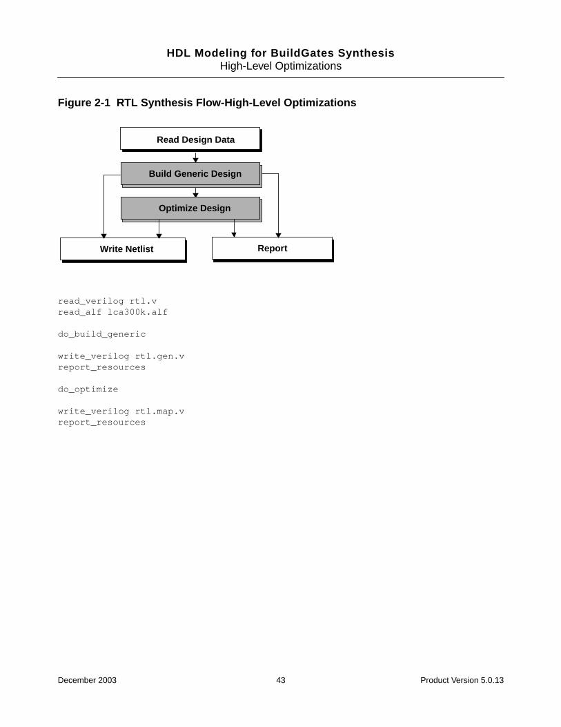
RTL Synthesis Flow
Figure 1-1 shows the typical RTL synthesis flow through a flow diagram and its correspondingTcl script. For information on reading libraries, see Using Timing Libraries in the TimingAnalysis for BuildGates Synthesis and Cadence Physically KnowledgeableSynthesis (PKS).
You can obtain information about the synthesized design after the do_build_generic andafter the do_optimize design phase. For example, after do_build_generic, thereport_resources command provides information about the initial architecture, size,format, and the corresponding RTL line number of arithmetic resources. After do_optimize,each arithmetic resource has a final architecture, which was selected by the tool whilesatisfying constraints during optimization.
You can also write a generic netlist after the do_build_generic design phase to verify thatthe generic netlist is functionally equivalent to the RTL design. Write the final netlist afteroptimization is complete. Use the write_adb command to preserve the generic netlist foroptimization in another session. The write_adb command uses a binary database to savethe netlist and any optimization-related attributes stored on netlist objects. These attributesare not written when the netlist is written in Verilog or VHDL format.
December 2003 25 Product Version 5.0.13

HDL Modeling for BuildGates SynthesisModeling and Synthesizing HDL Designs
Figure 1-1 RTL Synthesis Flow
read_verilog rtl.v
read_alf lca300k.alf
do_build_generic
write_verilog rtl.gen.v
report_resources
do_optimize
write_verilog rtl.map.v
report_resources
Tasks
The RTL Synthesis Flow shows the tasks when synthesizing an RTL design described in anHDL such as Verilog or VHDL. Each of these tasks are described in detail in the followingsections:
■ Read Design Data on page 27
■ Build Generic Design on page 28
■ Optimize Design on page 29
■ Report Resources on page 29
■ Write Netlist on page 30
Read Design Data
ReportWrite Netlist
Build Generic Design
Optimize Design
December 2003 26 Product Version 5.0.13
HDL Modeling for BuildGates SynthesisModeling and Synthesizing HDL Designs
Read Design Data
➤ Enter the appropriate command, such as read_vhdl for VHDL files or read_verilogfor Verilog files. For example, the following command reads in a pair of Verilog designs:
read_verilog controller.v dma.v
The first step in synthesizing a hardware description language (HDL) design is to read in theHDL design.
Read in the design data using the following commands:
■ read_adb: Use this command when the design is saved in an Ambit Database (adb)format. The adb format exchanges design information from one session to another. Theadvantages of using .adb files is the speed in which these files are written and read,compared to ASCII HDL files.
■ read_edif: Use this command when the design in an Electronic Design InterchangeFormat (EDIF). The EDIF format exchanges design data between different CADsystems, and between CAD systems and printed circuit fabrication and assembly. Theread_edif command directly generates the generic netlist.
■ read_verilog: Use this command for Verilog designs. The Verilog language describeshardware components as a set of modules. Each of these modules has an interface toother modules to describe interconnectivity. The top level module contains instances ofother modules (a hierarchy).
■ read_vhdl: Use this command for Very High Speed Integrated Circuit HardwareDescription Language (VHDL) designs. The VHDL format describes hardwarecomponents as a set of entities and architectures.
Note: For hierarchical designs, BuildGates does not require the designs to be read in anyparticular order. It is possible to read the designs in either a bottom-up or a top-down manner.However, the entire design must be loaded before synthesis. You can also read andsynthesize a large design one module at a time.
VHDL designs have the following restrictions: An entity must be read in before any of theentity’s architectures, and packages and package bodies must be read in prior to reading inany other packages, entities, or architectures that refer to them.
December 2003 27 Product Version 5.0.13
HDL Modeling for BuildGates SynthesisModeling and Synthesizing HDL Designs
Build Generic Design
➤ To build the generic design, enter the following command:
do_build_generic
After you read in all the design data, use the do_build_generic command to generate ahierarchical, gate-level netlist consisting of generic cells. The created netlist uses technologyindependent cells from the Ambit Technology Library (ATL) and the extended ATL (XATL)library. Arithmetic components use the AmbitWare Arithmetic Component Library (AWACL).
Use the do_build_generic command options to generate netlists for selected modules inthe design hierarchy. See Synthesizing a Specified Module on page 36 for information aboutthese options.
Note: In an EDIF design, it is not necessary to enter the do_build_generic command;the read_edif command directly generates the generic netlist from the EDIF description.
The do_build_generic command performs the following functions:
■ Generates an internal control and data flow graph (CDFG) to analyze the design.
■ Determines the number and type of registers (latches and flip-flops) needed to store datavalues in the design.
■ Determines the types and sizes of arithmetic components (adders, multipliers, and soon) required to implement the operations in the design.
■ Generates hardware for registers and arithmetic components and the appropriateinterconnect logic.
In addition, the do_build_generic command completes the following high-level genericoptimizations:
■ Resource Sharing
■ Tree Height Reduction
■ Implicit Constant Propagation
■ Common Sub-Expression Elimination (CSE)
■ Initial Architecture Selection
■ Extraction of Sum-of-Products Logic
■ MUX Extraction
■ Finite State Machine (FSM) Extraction
December 2003 28 Product Version 5.0.13

HDL Modeling for BuildGates SynthesisModeling and Synthesizing HDL Designs
These optimizations significantly improve your design’s area and performance. See Chapter2, High-Level Optimizations on page 41 for further information.
Optimize Design
➤ Once the generic netlist is generated, enter the following command to perform variouslogic mapping, and timing optimizations on the design:
do_optimize
In addition, the do_optimize command selects the optimal datapath architectures.
Report Resources
➤ Enter the following command to view information about the hardware resourcesgenerated to implement the design. Resources include flip-flops, latches, multiplexers,AmbitWare modules, and datapath modules.
report_resources
By default, the report_resources command provides information about the architecture,size, format, and line numbers of arithmetic resources that were generated to implement thearithmetic operations in the RTL design. After do_build_generic, the report shows theinitial architectures. After do_optimize, the report shows the final architecture that wasselected given the specified constraints.
In addition, the report_resources command reports the resources generated by each ofthe AmbitWare generators. See AmbitWare Generators on page 269 for more information.
Use the report_resources -hierarchical command for the following purposes:
■ To identify datapath operators
■ To examine how operators are merged
■ To examine the selected architecture of each (merged) operator
For more information see the Datapath for BuildGates Synthesis and Cadence PKS.
December 2003 29 Product Version 5.0.13

HDL Modeling for BuildGates SynthesisModeling and Synthesizing HDL Designs
Write Netlist
➤ Use one of the following commands to write out a generic netlist:
■ write_adb
■ write_edif
■ write_vhdl
■ write_verilog
Write out a generic netlist in VHDL or Verilog to verify that the generic netlist, produced bythe do_build_generic command, is functionally equivalent to the RTL design. Verify thedesign using techniques such as simulation or formal verification.
The final netlist is generated as the last step in the RTL synthesis flow. After optimization iscompete and the report results are satisfactory, save the final netlist.
Important
Use a binary netlist database (write_adb) to exchange database information andto preserve optimization-related attributes stored on netlist objects. These attributesare lost if the netlist is saved in a VHDL or a Verilog format, potentially resulting inlong optimization run times and poor quality of results.
Saving the Generic Netlist for Optimization in Another Session
➤ Use the write_adb command to save the generic netlist for optimization in anothersession.
The write_adb command writes design data stored by the shell to the database in theAmbit Synthesis database (ADB) file format. By default, the ADB netlist is a hierarchical netlistof the current module and all instances inside it. Use the ADB file to quickly load data andperform further synthesis or analysis. Use the read_adb command to load the data from the.adb file into the database.
December 2003 30 Product Version 5.0.13
HDL Modeling for BuildGates SynthesisModeling and Synthesizing HDL Designs
Simulating a Generic Netlist Before Optimization
To verify the functionality of the netlist generated by BuildGates using simulation, you needthe simulation models for the cells that comprise the netlist.
Netlists generated after the do_build_generic command consist of generic ATL andXATL cells.
➤ To simulate the netlist without the cell simulation models, use the -equation option withthe write_verilog or the write_vhdl command.
This writes out the generic netlist in the form of Boolean equations instead ofinstantiations of ATL and XATL cells. For example,
write_verilog -hierarchical -equation generic.v
write_vhdl -hierarchical -equation generic.vhd
The resulting Verilog or VHDL file provides functional information about the ATL and the XATLcomponents, and can be verified without the need for additional libraries.
Netlists generated after the do_optimize command consist of cells from the selected targettechnology. Verilog and VHDL simulation models for these are available directly from theASIC vendor that supplied the technology library.
Additional Information
■ Synthesizing Mixed VHDL and Verilog Designs on page 32
■ Querying the HDL Design Pool on page 33
■ Synthesizing a Specified Module on page 36
■ Synthesizing Multiple Top-Level Designs on page 37
■ Synthesizing Parameterized Designs on page 38
■ Synthesizing Designs with GTECH Cells on page 39
December 2003 31 Product Version 5.0.13
HDL Modeling for BuildGates SynthesisModeling and Synthesizing HDL Designs
Synthesizing Mixed VHDL and Verilog Designs
You can synthesize VHDL and Verilog designs in the same session. No special attributes orsynthesis directives are needed for mixed VHDL and Verilog designs. When using mixedVHDL and Verilog hierarchical designs, the following constraints apply:
■ Component instances in a Verilog module are resolved if a module or technology cellwith the exactS name is found. For example, an instance of a module named counteris resolved only with another VHDL or Verilog module named counter.
■ Component instances in a VHDL module are resolved in a case-insensitive manner. Forexample, an instance of a module named counter in a VHDL module is linked withother VHDL and Verilog modules named COUNTER, or Counter, and so on. An erroroccurs if there are multiple modules whose names match counter in a case-insensitivemanner.
■ VHDL modules that have similar names (identical letters but in different upper or lowercase form) are treated as identical modules. For example, if VHDL modules COUNTERand counter are read in sequentially, the latter module counter replaces COUNTER inthe module pool.
The following examples show a VHDL design, TOP_VHDL and a Verilog design,TOP_VERILOG. Each design instantiates a lower-level module. Instance I1 of COUNTER inentity TOP_VHDL is linked with the Verilog module counter because counter andCOUNTER are identical from a case-insensitive point of view. However, the instance inst1 ofcounter in module TOP_VERILOG is not linked to COUNTERS because a Veriloginstantiation requires an exact, case sensitive match.
Example 1-1 Instantiating a Counter in a VHDL Moduleentity TOP_VHDL is
...
I1 : COUNTER port map (...); -- linked with “counter”
end;
Example 1-2 Instantiating a Counter in a Verilog Modulemodule TOP_VERILOG (...);
...
counter inst1 (...); // not linked with "COUNTER"
endmodule
December 2003 32 Product Version 5.0.13
HDL Modeling for BuildGates SynthesisModeling and Synthesizing HDL Designs
Querying the HDL Design Pool
Design data is often organized into tens or even hundreds of HDL files. You can investigatethe design hierarchy right after the HDL files are read into BuildGates Synthesis. Queriesdetermine which subtrees in the design hierarchy need to be synthesized. Use these queriesto generate Makefile-like scripts for managing the design’s generic build and optimizationsteps.
Use the following commands to query the entire pool of HDL designs read in using theread_vhdl or the read_verilog commands:
■ get_hdl_top_level (page 35)
■ get_hdl_hierarchy (page 35)
■ get_hdl_type (page 36)
■ get_hdl_file (page 36)
To illustrate the get_hdl commands, consider the following VHDL design, shown inExample 1-3. It consists of three entities: TOP, BOT, and BOTG. Assume that the design is ina VHDL file called design.vhd that has been read in using the read_vhdl command.
December 2003 33 Product Version 5.0.13

HDL Modeling for BuildGates SynthesisModeling and Synthesizing HDL Designs
Example 1-3 VHDL Design Consisting of Three Entitiesentity BOTG is
generic (WIDTH : natural := 1);
port (Q: out bit_vector(WIDTH-1 downto 0));
end;
architecture A of BOTG is
begin
Q <= (others => ’1’);
end;
entity BOT is
port (Q: out integer);
end;
architecture A of BOT is
begin
Q <= 25;
end;
entity TOP is
port (AO: out bit_vector(7 downto 0);
BO: out integer);
end;
architecture A of TOP is
begin
IB : entity work.BOT port map (BO);
IA : entity work.BOTG generic map (8) port map (AO);
end;
After do_build_generic, Figure 1-2 shows the schematic representation of the threeentity VHDL design.
December 2003 34 Product Version 5.0.13
HDL Modeling for BuildGates SynthesisModeling and Synthesizing HDL Designs
Figure 1-2 Schematic of VHDL Design with Three Entities
Using the get_hdl_top_level Command
➤ Use the get_hdl_top_level command to display a list containing the names of all toplevel designs (designs that are not instantiated by any other design).
For example, from the VHDL Example 1-3 above, the command:
get_hdl_top_level
yields the following output:
TOP
Using the get_hdl_hierarchy Command
➤ Use the get_hdl_hierarchy command to display the design hierarchy.
For each design, the command lists the names of the designs that were instantiatedwithin it (design hierarchical) and determines if the instantiations are parameterized(using parameters in Verilog or generics in VHDL).
For example, from the VHDL Example 1-3 above, the command:
get_hdl_hierarchy
yields the following output:
{TOP {{BOT n} {BOTG p}}} {BOT {}} {BOTG {}}
December 2003 35 Product Version 5.0.13
HDL Modeling for BuildGates SynthesisModeling and Synthesizing HDL Designs
The output indicates that TOP instantiates both BOT (n represents a non-parameterizedinstantiation) and BOTG (p indicates a parameterized instantiation, since design BOTGcontains generics). BOT and BOTG do not instantiate any other designs.
➤ Specify the module to obtain the hierarchy for a specific design. For example:
get_hdl_hierarchy TOP
yields the following output:
{TOP {{BOT n} {BOTG p}}}
Using the get_hdl_type Command
➤ Use the get_hdl_type command to determine the language (VHDL or Verilog) of thedescribed design.
For example entering the following command:
get_hdl_type TOP
yields the following output:
VHDL
Using the get_hdl_file Command
➤ Use the get_hdl_file command to return the name of the HDL source file.
For example, entering the following command:
get_hdl_file BOTG
yields the following output:
design.vhd
Synthesizing a Specified Module
➤ Use the -module option with the do_build_generic command to synthesize ageneric netlist for a named module (or entity in VHDL) and all sub-modules in thehierarchy. For example:
do_build_generic -module des_top
The -module option selects the named module as the top of the design hierarchy and as thedefault top timing module.To determine which module will serve as the starting point forsynthesis, the tool looks for an exact match of the specified module in the HDL design pool.If a unique match is found, then that module is used as a starting point for synthesis.
December 2003 36 Product Version 5.0.13

HDL Modeling for BuildGates SynthesisModeling and Synthesizing HDL Designs
Synthesizing Multiple Top-Level Designs
➤ Use the -module option, the -all option, or the foreach Tcl command to synthesizeall the modules (or entities in VHDL) in the design hierarchy.
The do_build_generic command synthesizes all modules in the design hierarchy into ageneric netlist. If there are multiple top-level modules in the design hierarchy, indicate thespecific module in the design hierarchy to synthesize.
For example, assume that there are three top-level modules in the HDL design pool. Enteringthe following command:
get_hdl_top_level
identifies the three top-level modules:
TOP1 TOP2 TOP3
Examples 1-4 through 1-6 show how to synthesize top-level designs in the HDL design pool:
Example 1-4 Using the -module Option for Each of the Top-Level Designsdo_build_generic -module TOP1
do_build_generic -module TOP2
do_build_generic -module TOP3
Example 1-5 Using the -all Optiondo_build_generic -all
Example 1-6 Using the foreach TCL Commandforeach top [get_hdl_top_level] {
do_build_generic -module $top
}
Note: For multiple top-level designs, an error results if the do_build_generic commandis used without either the -all or -module option.
December 2003 37 Product Version 5.0.13

HDL Modeling for BuildGates SynthesisModeling and Synthesizing HDL Designs
Synthesizing Parameterized Designs
Use the do_build_generic command to propagate specified values and to specify valuesfor instantiation.
Propagating Specified Values for Instantiation
The do_build_generic command automatically elaborates the design by propagatinggeneric values (parameters in Verilog) specified for instantiation as shown in Example 1-7.
Example 1-7 Automatic ElaborationEntity BOT is
generic (L, R: natural := 1);
port (O: out bit_vector(L downto R));
end;
Architecture A of BOT is
begin
O <= (others => ’1’);
end;
Entity TOP is
port (O: out bit_vector(7 downto 0));
end;
Architecture A of TOP is
begin
I8 : entity work.BOT generic map (7, 0) port map (O);
end;
In this example, the do_build_generic command builds the modules TOP andBOT_L7_R0 (derived from the instance I8 in design TOP). The actual values (7 and 0) of thetwo generics (L and R) provided in instance I8 override the default values for generics in theentity definition for BOT.
December 2003 38 Product Version 5.0.13
HDL Modeling for BuildGates SynthesisModeling and Synthesizing HDL Designs
Synthesizing Designs with GTECH Cells
You can synthesize designs that use GTECH cells. To read designs that instantiate GTECHcells, do the following:
■ For structural designs:
read_alf gtech.alf
read_verilog (read_vhdl) -structural design.v (.vhd)
■ For partly structural designs:
read_verilog (read_vhdl) design.v (.vhd)
do_build_generic
■ To map these GTECH components to ATL/XATL components:
do_xform_unmap -hier
■ To map these components to another target library:
do_xform_unmap -hier
read_tlf new_target_library.tlf
set_global target_technology new_target_library
do_xform_map -hier
December 2003 39 Product Version 5.0.13
HDL Modeling for BuildGates SynthesisModeling and Synthesizing HDL Designs
Specifying Values for Instantiation
While automatic elaboration works for designs that are instantiated in a higher level design,some applications require an override of the default parameter values directly from thedo_build_generic command (as in elaborating top-level modules with different values ofthe parameters).
➤ To override the default parameter values, use the -parameter option, as shown inExample 1-8. This option specifies the values to use for the indicated generics.
Example 1-8 Overriding the Default Parameter Values
Synthesizing the design BOT with generic values L=4 and R=1:
do_build_generic -module BOT -parameter {{L 3} {R 2}}
yields the following output:
Info: Building generic design BOT (instantiated from the command line)with the parameter(s) L=3, R=2 <CDFG-340>.
Info: Processing design BOT_L3_R2 <CDFG-303>.
Finished processing module: BOT_L3_R2 <MODGEN-110>.
Note: An error occurs if a generic name specified using the -parameter option is not a validgeneric name for that design.
Troubleshooting
Look for troubleshooting information at the end of each chapter. Additional troubleshootinginformation can be found in the latest version of Known Problems and Solutions forBuildGates Synthesis and Cadence PKS that accompanied your release.
December 2003 40 Product Version 5.0.13
HDL Modeling for BuildGates Synthesis
2High-Level Optimizations
This chapter describes high-level optimizations for RTL Verilog or VHDL designs and includesthe following sections:
■ Overview on page 42
■ Tasks on page 44
■ Additional Information on page 57
■ Troubleshooting on page 66
December 2003 41 Product Version 5.0.13

HDL Modeling for BuildGates SynthesisHigh-Level Optimizations
Overview
This chapter describes the high-level optimizations that are performed on RTL designs duringsynthesis. Control these optimizations using the set_global command. All globals have adefault value when you start a new shell session. Extensive experiments have identifiedthat the default values are the best for most designs. However, you may attain better resultsby changing a global value with the set_global command.
Once a global is set to a new value, the global retains that value for the current shell sessionuntil you set a new value for the global using the set_global command. Use theget_global command to get the value of any global. Use the reset_global command toset the value of any global to its default value.
Optimization is automatic when you use the HDL optimization commands. The goal ofoptimization is to generate the best design, in terms of area and delay, that meets specifiedconstraints. A design that is optimized for minimal area is often the one that consumesminimal power for a given frequency.
Perform RTL synthesis as shown by the flow diagram and the corresponding Tcl script as inFigure 2-1. High-level optimizations are performed during the do_build_generic and thedo_optimize design phases. You can generate reports, such as report_resources,after the do_build_generic and do_optimize design phases. See Chapter 1, “Modelingand Synthesizing HDL Designs,” for detailed information on the RTL synthesis flow.
The high-level optimization techniques are described in the Tasks section.
December 2003 42 Product Version 5.0.13
HDL Modeling for BuildGates SynthesisHigh-Level Optimizations
Figure 2-1 RTL Synthesis Flow-High-Level Optimizations
read_verilog rtl.vread_alf lca300k.alf
do_build_generic
write_verilog rtl.gen.vreport_resources
do_optimize
write_verilog rtl.map.vreport_resources
Read Design Data
ReportWrite Netlist
Build Generic Design
Optimize Design
December 2003 43 Product Version 5.0.13
HDL Modeling for BuildGates SynthesisHigh-Level Optimizations
Tasks
Control the following RTL high-level optimizations by specifying globals during thedo_build_generic and do_optimize design phases.
■ Resource Sharing on page 45 – Reduces the number of logic modules needed toimplement HDL arithmetic operations.
■ Tree Height Reduction (THR) on page 46 – Minimizes the delay of complex arithmeticexpressions.
■ Implicit Constant Propagation (ICP) on page 50 – Reduces area and delay by identifyingvariables in the RTL design that can be implemented as constants in the synthesizeddesign.
■ Common Sub-Expression Elimination (CSE) on page 51 – Removes redundantarithmetic expressions from the RTL description to minimize the hardware componentsrequired to implement those expressions.
■ Architecture Selection on page 53 – Sets the default architecture used to implementadders and multipliers.
■ Extraction of Sum-of-Products (SOP) Logic on page 54– Reduces area by usingspecialized logic optimization techniques on constant case statements.
■ Multiplexer Optimization on page 55– Reduces runtime by defining the threshold sizebelow which all muxes are dissolved.
■ Finite State Machine (FSM) Extraction on page 56 – Extracts the State Transition Tablefor the Finite State Machine.
December 2003 44 Product Version 5.0.13
HDL Modeling for BuildGates SynthesisHigh-Level Optimizations
Resource Sharing
➤ Set the following global to true to turn on resource sharing optimization:
set_global hdl_resource_sharing {true | false}
Default: true
Follow these guidelines when using the hdl_resouce_sharing global command. Formore information on resource sharing, see Additional Information on page 57.
■ Resource sharing takes place during the do_build_generic and the do_optimizedesign stages of the RTL Synthesis flow.
■ Set the global hdl_resource_sharing variable to true before using thedo_build_generic command. This lets the tool collect information for sharing.
■ Sharing is performed at the end of the timing optimization phase to reclaim area withoutworsening slack. During the do_optimize phase, set the globalhdl_resource_sharing variable to false to disable resource sharing, or it willattempt to reclaim area after timing optimizations.
■ Resource sharing requires the HDL to have arithmetic operations in different branchesof a single conditional construct such as a case or an if statement.
■ Sharing is not performed across different conditional constructs or HDL modules.
■ Carry-save clusters are unsuitable for resource sharing, which limits the number ofsharing possibilities in a design. See Resource Sharing with Carry-Save Inferences onpage 65 for additional information.
■ False paths are not identified, which can cause pessimistic timing analysis, and limits thenumber of sharing decisions in a design.
See Additional Information on page 57 for more information on resource sharing.
December 2003 45 Product Version 5.0.13
HDL Modeling for BuildGates SynthesisHigh-Level Optimizations
Tree Height Reduction (THR)
➤ Set the following global to true to enable tree height reduction:
set_global hdl_tree_height_reduction {true | false}
Default: true (BuildGates Synthesis)Default: false (BuildGates Extreme and PKS)
Note: The default is false in BuildGates Extreme and PKS because THR can reducethe effectiveness of some datapath optimizations.
THR is done during the do_build_generic phase of the design flow.
Tree Height Reduction (THR) is a timing independent optimization technique for reducing theheight of an arithmetic expression tree by balancing its subtrees. The height of a tree isbalanced when the height of its left and right subtrees do not differ by more than one.Theheight of the tree is equal to the number of steps needed to compute the expression, so thesmaller the height of the expression tree, the smaller the delay in computing the expression.The following sections describe how to use THR to improve slack, area, and delay.
As shown in Example 2-1, THR improves slack and area of datapath rich designs that havechains of adders, multipliers, or subtractors. The design can have a combination of adders,subtractors, and multipliers within the same expression, or it can have an individual chain ofadders, a chain of subtractors, or a chain of multipliers.
Example 2-1 THR Produces Better Slack and Area
THR improves performance by reducing the critical path delay. You can get an area gain bydoing a bit-width matched THR.
The expression z= a+ b+ c+ d in Example 2-2 is implemented with a skewed adder tree witha height of 3, as shown in Figure 2-2 when THR is disabled.
December 2003 46 Product Version 5.0.13

HDL Modeling for BuildGates SynthesisHigh-Level Optimizations
Example 2-2 Modeling Bit-Width Matchingmodule thr (z,a,b,c,d);
input [1:0] a,c;
input [2:0] b,d;
output [5:0] z;
reg [5:0] z;
always @(a or b or c or d)
begin
z = a + b + c + d;
end
endmodule
Figure 2-2 Matching Bit-Widths with THR Disabled
When THR is enabled, the expression is implemented with a balanced tree with a height of2, as shown in Figure 2-3. Whenever possible, the THR optimization assigns expression inputvariables with similar bit-width to a single hardware component to minimize the size of thatcomponent. This bit-width matching may result in smaller adders, subtractors, andmultipliers, which in turn, results in a smaller area.
December 2003 47 Product Version 5.0.13

HDL Modeling for BuildGates SynthesisHigh-Level Optimizations
Figure 2-3 Matching Bit-Widths with THR Enabled
Using Parentheses with Tree Height Reduction
THR honors parentheses in an expression. THR does not rebalance expressions acrossparentheses, but lets you use parentheses as directives to control how you want to rebalancethe expression tree. Example 2-3 shows how you can use parentheses to separate earlyarriving inputs from late arriving inputs.
Example 2-3 Modeling Parentheses with Tree Height Reductionmodule thr (z,a,b,c,d,e,f);
input [2:0] a,b,c,d,e,f;
output [2:0] z;
reg [2:0] z;
always @(a or b or c or d or e or f)
begin
z = (a + b + c + d) + (e + f);
end
endmodule
If late arriving inputs are not separated from the early arriving inputs, THR may generate astructure whose critical path is worse than if THR were disabled.
Figure 2-4 shows a structure using parenthesis with THR disabled.
December 2003 48 Product Version 5.0.13
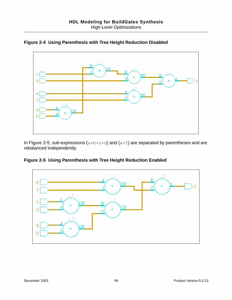
HDL Modeling for BuildGates SynthesisHigh-Level Optimizations
Figure 2-4 Using Parenthesis with Tree Height Reduction Disabled
In Figure 2-5, sub-expressions (a+b+c+d) and (e+f) are separated by parentheses and arerebalanced independently.
Figure 2-5 Using Parenthesis with Tree Height Reduction Enabled
December 2003 49 Product Version 5.0.13

HDL Modeling for BuildGates SynthesisHigh-Level Optimizations
Implicit Constant Propagation (ICP)
Implicit constant propagation is an optimization technique that replaces program variableswith constant values within conditional statements. ICP determines whether the value of avariable in a conditional clause evaluates to a constant, and if it does, propagates thatconstant to all uses of the variable in the relevant branch of the condition. The goal of constantpropagation is to discover values that are constant on all possible executions of a programand to propagate these constant values as far forward through the program as possible. Theadvantage of the ICP optimization is shown in Example 2-4, where the constant 3 ispropagated to the subtraction operation, eliminating the need for a subtractor in the netlist.
Note: Implicit constant propagation is done by default by the do_build_genericcommand.
Example 2-4 Applying ICP to an if Statementmodule icp (z,a);
input [1:0] a;
output [1:0] z;
reg [1:0] z;
always @(a)
begin
if (a == 3)
z = a - 1;
else
z = a;
end
endmodule
December 2003 50 Product Version 5.0.13

HDL Modeling for BuildGates SynthesisHigh-Level Optimizations
Common Sub-Expression Elimination (CSE)
➤ Set the following global to true to enable the Common Sub-Expression Eliminationoptimization:
set_global hdl_common_subexpression_elimination {true | false}
Default: true
Common Sub-Expression Elimination (CSE) is an optimization technique that removesredundant arithmetic expressions from the RTL description to minimize the hardwarerequired to implement those expressions. Figure 2-6 shows the generic netlist generated forthe module cse shown in Example 2-5 with CSE enabled.
Example 2-5 RTL Description with a Redundant Arithmetic Expressionmodule cse (z,a,b,c,d,sel);
input sel;
input [7:0] a,b,c,d;
output [15:0] z;
reg [15:0] z;
always @ (a or b or c or d or sel)
begin
if (sel)
z = a * b + c;
else
z = d + a * b;
end
endmodule
December 2003 51 Product Version 5.0.13

HDL Modeling for BuildGates SynthesisHigh-Level Optimizations
Figure 2-6 Generic Netlist Using Common Sub-Expression Elimination
Figure 2-7 shows two multipliers used to implement output z when CSE is disabled.
Figure 2-7 Generic Netlist with Common Sub-Expression Elimination Disabled
December 2003 52 Product Version 5.0.13

HDL Modeling for BuildGates SynthesisHigh-Level Optimizations
Architecture Selection
➤ Use the following global to set the default adder architecture used to implement finaladders:
set_global aware_adder_architecture {ripple | csel | cla | fcla}
Default: fcla
A synthesis tool does not treat an adder as a single truth table during implementation.Instead, the tool employs a known, pre-defined scheme to compose the adder. Such ascheme is known as the architecture of an adder.
Cadence PKS and BuildGates Extreme Synthesis support four carry-propagate adderarchitectures that trade off between area and timing (seeTable 2-1).
See Resource Sharing with Architecture Selection on page 65 for information on howresource sharing interacts with adder architecture selection.
Table 2-1 Supported Adder Architectures
Architecture Description
fcla (fast carry look ahead adder) Provides a solution that is usually the fastestand largest. A regular structure with a largetotal wire length.
csel (carry select adder) Provides a solution with the best/moderatearea-delay product. A regular structure withlow total wire length.
cla (carry look ahead adder) Provides the best area-delay productsolution. A regular structure but much morewire length than the csel.
ripple (ripple adder) Provides a solution with the smallest area. Avery dense structure with the least total wirelength.
December 2003 53 Product Version 5.0.13

HDL Modeling for BuildGates SynthesisHigh-Level Optimizations
Extraction of Sum-of-Products (SOP) Logic
➤ Set the following global to true to automatically extract logic from case statements thatcan be represented by Boolean equations in sum-of-products form:
set_global hdl_extract_sum_of_products_logic {true | false}
Default: true
A variable that is assigned only constant values within a case statement, such as variable zcan be represented by a Boolean equation that is in a sum-of-products (SOP) form as shownin Figure 2-8. SOP logic that is identified and extracted during the do_build_genericdesign phase can be minimized during the do_optimize design phase with specialized andefficient logic optimization techniques.
Figure 2-8 Extracting Sum-of-Products Logic from a Constant case Statementmodule sop (z,d);
input [2:0] d;
output z;
reg z;
always @ (d)
begin
case (d)
3’b000 : z = 1’b0;
3’b001 : z = 1’b0;
3’b010 : z = 1’b0;
3’b011 : z = 1’b1;
3’b100 : z = 1’b0;
3’b101 : z = 1’b1;
3’b110 : z = 1’b1;
3’b111 : z = 1’b1;
endcase
end
endmodule
December 2003 54 Product Version 5.0.13
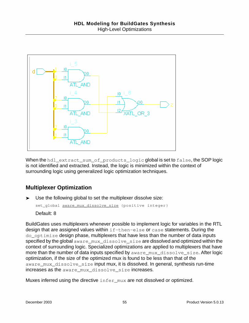
HDL Modeling for BuildGates SynthesisHigh-Level Optimizations
When the hdl_extract_sum_of_products_logic global is set to false, the SOP logicis not identified and extracted. Instead, the logic is minimized within the context ofsurrounding logic using generalized logic optimization techniques.
Multiplexer Optimization
➤ Use the following global to set the multiplexer dissolve size:
set_global aware_mux_dissolve_size {positive integer}
Default: 8
BuildGates uses multiplexers whenever possible to implement logic for variables in the RTLdesign that are assigned values within if-then-else or case statements. During thedo_optimize design phase, multiplexers that have less than the number of data inputsspecified by the global aware_mux_dissolve_size are dissolved and optimized within thecontext of surrounding logic. Specialized optimizations are applied to multiplexers that havemore than the number of data inputs specified by aware_mux_dissolve_size. After logicoptimization, if the size of the optimized mux is found to be less than that of theaware_mux_dissolve_size input mux, it is dissolved. In general, synthesis run-timeincreases as the aware_mux_dissolve_size increases.
Muxes inferred using the directive infer_mux are not dissolved or optimized.
December 2003 55 Product Version 5.0.13
HDL Modeling for BuildGates SynthesisHigh-Level Optimizations
Finite State Machine (FSM) Extraction
➤ Use the following command to enable finite state machine extraction optimization:
do_build_generic -extract_fsm
After reading the design data into the BuildGates Synthesis software, you can extractand view the state transition table for the FSM. The state transition table containsinformation about equivalent states, initial states, and state encodings.
Use Cadence synthesis pragmas to perform FSM optimizations. See Chapter 6,Optimizing and Structuring Finite State Machines on page 221 for more information onFSM optimizations.
December 2003 56 Product Version 5.0.13

HDL Modeling for BuildGates SynthesisHigh-Level Optimizations
Additional Information
The following sections provide additional information on resource sharing:
■ Sharing Hardware Resources on page 58
■ Minimizing Implementation Area by Matching Bit Widths on page 59
■ Minimizing MUX Overhead by Matching Common HDL Variables on page 60
■ Removing Redundant Multiplexers on page 61
■ Sharing Multi-Function Operations on page 61
■ Sharing Across Nested Conditions on page 61
■ Avoiding Combinational Loops on page 62
■ Interacting with Other Optimization Techniques on page 63
December 2003 57 Product Version 5.0.13

HDL Modeling for BuildGates SynthesisHigh-Level Optimizations
Sharing Hardware Resources
Resource sharing is an optimization technique that reclaims design area (reduces gatecount) without worsening design performance. This optimization is based on the principle thattwo similar arithmetic operations can be performed on one arithmetic hardware component ifthey are never used at the same time.
Use this technique to share hardware resources across portions of the design. During thesynthesis flow resource sharing is performed for area reclamation as a post timingoptimization step. Sharing is performed incrementally by merging two datapath modules intoone. This guarantees that the design timing constraints are not violated, resulting in a designwith smaller area and possibly reduced delay.
Resource sharing provides the following capabilities:
■ Makes sharing decisions after timing optimizations when accurate timing and areaestimates are available.
■ Enhances Datapath Synthesis if the design netlist contains datapath modules thatimplement complex arithmetic functions such as a sum of products (a+b*c). Sharingspontaneously synthesizes an equivalent module that implements the functionality of two(complex) datapath modules.
■ Identifies RTL sharing possibilities automatically as opposed to being driven by user-specified pragmas. The automated feature lets appropriate sharing decisions be basedon timing constraints, which are usually hard for you to determine from the RTL code andbare input-output constraints.
■ Incorporates many additional features, such as redundant mux removal, name and bit-width based matching, incremental and nested-condition sharing that provides apowerful framework for improving area. These are described in the following sections.
Sharing Two Arithmetic Expressions
Resource sharing attempts to share arithmetic expressions that are specified in mutuallyexclusive segments of the HDL source, that is, the arithmetic expressions are in differentparts (or branches) of a conditional HDL construct.
Figure 2-9 shows how to model two arithmetic expressions that you want to share. Theseexpressions are mutually exclusive, because they are in different parts of the same ifstatement. The shared hardware (which implements one adder) selects the appropriateinputs depending on the value of q.
December 2003 58 Product Version 5.0.13
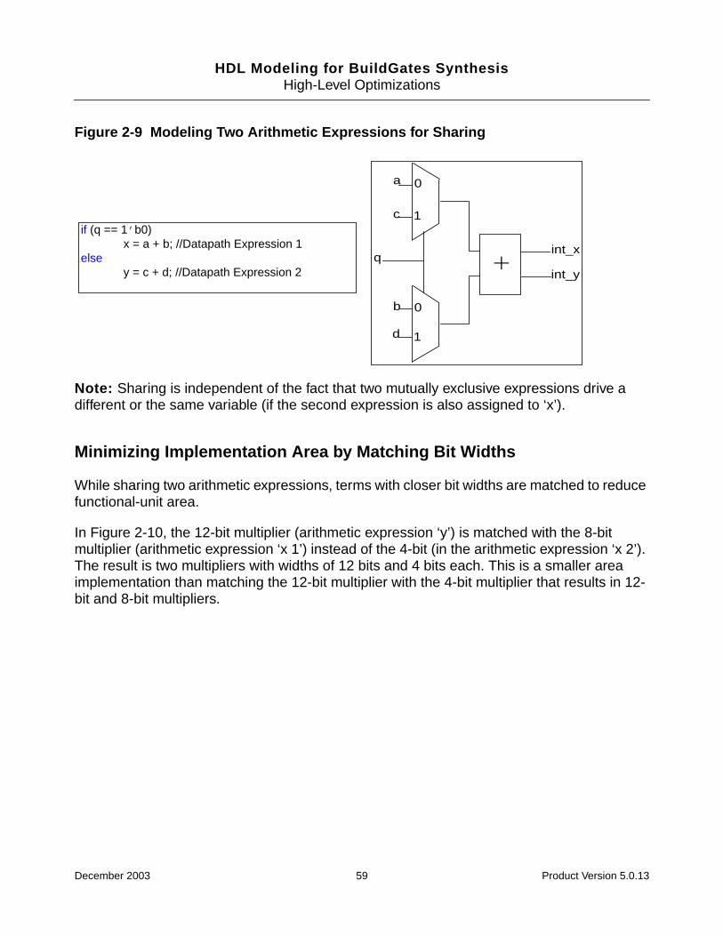
HDL Modeling for BuildGates SynthesisHigh-Level Optimizations
Figure 2-9 Modeling Two Arithmetic Expressions for Sharing
Note: Sharing is independent of the fact that two mutually exclusive expressions drive adifferent or the same variable (if the second expression is also assigned to ‘x’).
Minimizing Implementation Area by Matching Bit Widths
While sharing two arithmetic expressions, terms with closer bit widths are matched to reducefunctional-unit area.
In Figure 2-10, the 12-bit multiplier (arithmetic expression ‘y’) is matched with the 8-bitmultiplier (arithmetic expression ‘x 1’) instead of the 4-bit (in the arithmetic expression ‘x 2’).The result is two multipliers with widths of 12 bits and 4 bits each. This is a smaller areaimplementation than matching the 12-bit multiplier with the 4-bit multiplier that results in 12-bit and 8-bit multipliers.
d
b
c
a
qint_x
int_y
0
1
0
1
+
if (q == 1’b0)x = a + b; //Datapath Expression 1
elsey = c + d; //Datapath Expression 2
December 2003 59 Product Version 5.0.13
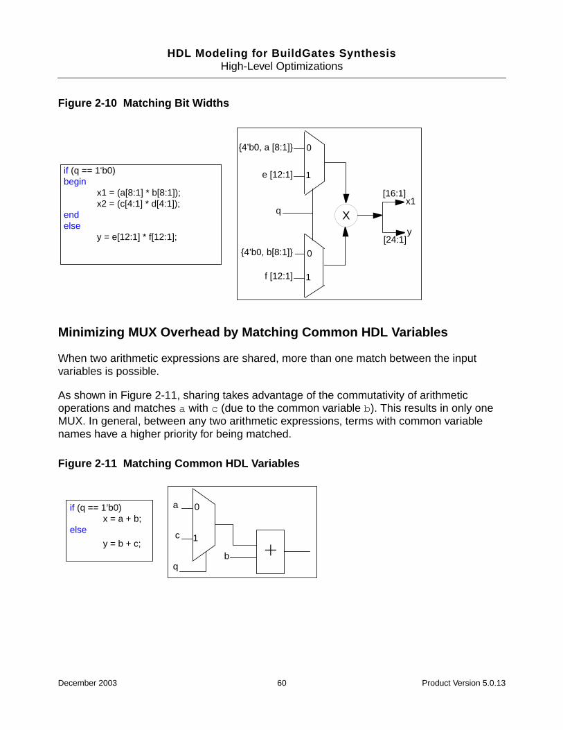
HDL Modeling for BuildGates SynthesisHigh-Level Optimizations
Figure 2-10 Matching Bit Widths
Minimizing MUX Overhead by Matching Common HDL Variables
When two arithmetic expressions are shared, more than one match between the inputvariables is possible.
As shown in Figure 2-11, sharing takes advantage of the commutativity of arithmeticoperations and matches a with c (due to the common variable b). This results in only oneMUX. In general, between any two arithmetic expressions, terms with common variablenames have a higher priority for being matched.
Figure 2-11 Matching Common HDL Variables
f [12:1]
{4’b0, b[8:1]}
e [12:1]
{4’b0, a [8:1]}
q
0
1
0
1
X
[16:1]
[24:1]
x1
y
if (q == 1‘b0)begin
x1 = (a[8:1] * b[8:1]);x2 = (c[4:1] * d[4:1]);
endelse
y = e[12:1] * f[12:1];
a
c
0
1
qb +
if (q == 1’b0)x = a + b;
else
y = b + c;
December 2003 60 Product Version 5.0.13

HDL Modeling for BuildGates SynthesisHigh-Level Optimizations
Removing Redundant Multiplexers
In some designs, modules selected for sharing are driving inputs of the same multiplexer. Thishappens when the unshared arithmetic expressions are driving the same HDL variable. InFigure 2-12, after the arithmetic expressions are shared, the multiplexers at the outputbecomes redundant because it selects between the fan-outs from the shared module.Sharing performs logic optimization to identify and remove redundant multiplexers. This iscritical when satisfying a tight timing constraint.
Figure 2-12 Removing Redundant Multiplexers
Sharing Multi-Function Operations
Sharing is done across different arithmetic operations if there are no available operations ofthe same type. The following are the multi-function operations that are shared:
■ Subtraction operations are shared with addition operations.
■ Certain relational Operators of differing types are shared.
Sharing Across Nested Conditions
Sharing is done across nested conditions in the design. In Figure 2-13, the multiplier isshared across two conditional statements (s and r). The second multiplication (d * a) isassigned to y on the condition s=11&r=1, whereas the first expression is assigned to x onthe condition s=01. Even though there is two-level nesting, the mutual exclusion of themultiplication is based on the value of s. Therefore, the optimized control logic is dependentonly on r and the optimized control logic (dependent only on s[1]) is automaticallygenerated during sharing.
a
b0
1
q
x
+
c
d
+
+
if (q == 1’b0)x_mux = a + b;
elsex_mux = c + d;
December 2003 61 Product Version 5.0.13
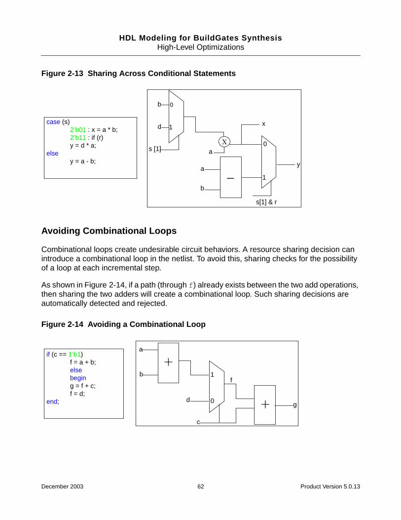
HDL Modeling for BuildGates SynthesisHigh-Level Optimizations
Figure 2-13 Sharing Across Conditional Statements
Avoiding Combinational Loops
Combinational loops create undesirable circuit behaviors. A resource sharing decision canintroduce a combinational loop in the netlist. To avoid this, sharing checks for the possibilityof a loop at each incremental step.
As shown in Figure 2-14, if a path (through f) already exists between the two add operations,then sharing the two adders will create a combinational loop. Such sharing decisions areautomatically detected and rejected.
Figure 2-14 Avoiding a Combinational Loop
b
d
0
1
s [1] a
y
1
0
s[1] & r
a
b
x
X
-
case (s)2’b01 : x = a * b;2’b11 : if (r)y = d * a;
elsey = a - b;
a
b 1
0d
c
g
f
+
+
if (c == 1’b1)f = a + b;elsebeging = f + c;f = d;
end;
December 2003 62 Product Version 5.0.13

HDL Modeling for BuildGates SynthesisHigh-Level Optimizations
Interacting with Other Optimization Techniques
Resource Sharing works with Datapath optimizations including Operator Merging,Architecture Selection, and Carry-save inferencing. In addition, Resource Sharingcomplements the Low-power Synthesis sleep-mode operation.These interactions areexplained in the following sections:
■ Resource Sharing with Operator Merging on page 63
■ Resource Sharing with Operator Merging on page 63
■ Resource Sharing with Carry-Save Inferences on page 65
■ Resource Sharing with Sleep-Mode Operation on page 65
Resource Sharing with Operator Merging
A powerful optimization feature of the resource sharing implementation is its ability to sharearbitrary (or partial) arithmetic expressions. Operator merging (see Example 2-1) clusters thedatapath operations and results in improved delay and area.
Example 2-1 Operator Mergingmodule foo (a,b,c,d,e,f,s,x,y);
input s;
input [7:0] a,b;
input [3:0] c,d;
input [11:0] e,f;
output [23:0] y;
output [16:0] x;
reg [16:0] x;
reg [23:0] y;
always @ (a or b or c or d or e or f or s)
begin
if (s)
x = (a * b) + (c * d);
else
y = e * f;
end
endmodule
December 2003 63 Product Version 5.0.13
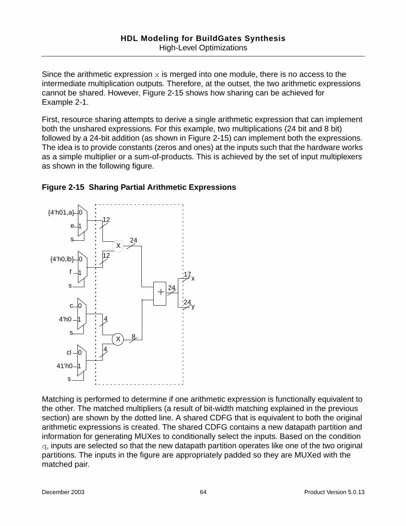
HDL Modeling for BuildGates SynthesisHigh-Level Optimizations
Since the arithmetic expression x is merged into one module, there is no access to theintermediate multiplication outputs. Therefore, at the outset, the two arithmetic expressionscannot be shared. However, Figure 2-15 shows how sharing can be achieved forExample 2-1.
First, resource sharing attempts to derive a single arithmetic expression that can implementboth the unshared expressions. For this example, two multiplications (24 bit and 8 bit)followed by a 24-bit addition (as shown in Figure 2-15) can implement both the expressions.The idea is to provide constants (zeros and ones) at the inputs such that the hardware worksas a simple multiplier or a sum-of-products. This is achieved by the set of input multiplexersas shown in the following figure.
Figure 2-15 Sharing Partial Arithmetic Expressions
Matching is performed to determine if one arithmetic expression is functionally equivalent tothe other. The matched multipliers (a result of bit-width matching explained in the previoussection) are shown by the dotted line. A shared CDFG that is equivalent to both the originalarithmetic expressions is created. The shared CDFG contains a new datapath partition andinformation for generating MUXes to conditionally select the inputs. Based on the conditionq, inputs are selected so that the new datapath partition operates like one of the two originalpartitions. The inputs in the figure are appropriately padded so they are MUXed with thematched pair.
{4’h01,a} 0
1e
s
0
1
{4’h0,lb}
f
s
0
14’h0
s
0
1
cl
41’h0
s
c
X
X
+
12
12
24
4
4
8
24x
y
17
24
December 2003 64 Product Version 5.0.13
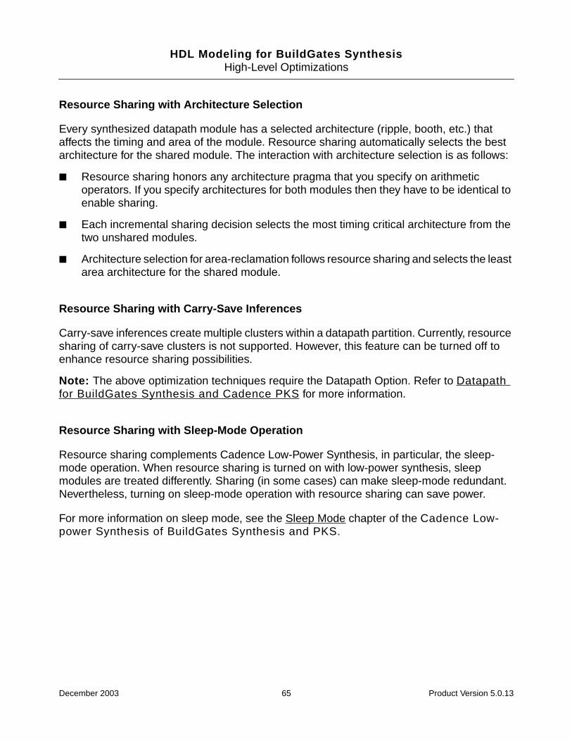
HDL Modeling for BuildGates SynthesisHigh-Level Optimizations
Resource Sharing with Architecture Selection
Every synthesized datapath module has a selected architecture (ripple, booth, etc.) thataffects the timing and area of the module. Resource sharing automatically selects the bestarchitecture for the shared module. The interaction with architecture selection is as follows:
■ Resource sharing honors any architecture pragma that you specify on arithmeticoperators. If you specify architectures for both modules then they have to be identical toenable sharing.
■ Each incremental sharing decision selects the most timing critical architecture from thetwo unshared modules.
■ Architecture selection for area-reclamation follows resource sharing and selects the leastarea architecture for the shared module.
Resource Sharing with Carry-Save Inferences
Carry-save inferences create multiple clusters within a datapath partition. Currently, resourcesharing of carry-save clusters is not supported. However, this feature can be turned off toenhance resource sharing possibilities.
Note: The above optimization techniques require the Datapath Option. Refer to Datapathfor BuildGates Synthesis and Cadence PKS for more information.
Resource Sharing with Sleep-Mode Operation
Resource sharing complements Cadence Low-Power Synthesis, in particular, the sleep-mode operation. When resource sharing is turned on with low-power synthesis, sleepmodules are treated differently. Sharing (in some cases) can make sleep-mode redundant.Nevertheless, turning on sleep-mode operation with resource sharing can save power.
For more information on sleep mode, see the Sleep Mode chapter of the Cadence Low-power Synthesis of BuildGates Synthesis and PKS.
December 2003 65 Product Version 5.0.13
HDL Modeling for BuildGates SynthesisHigh-Level Optimizations
Troubleshooting
Additional troubleshooting information can be found in the latest version of Known Problemsand Solutions for BuildGates Synthesis and Cadence PKS that came with your release.
December 2003 66 Product Version 5.0.13
HDL Modeling for BuildGates Synthesis
3Synthesizing Verilog Designs
This chapter explains how to synthesize Verilog designs using Verilog synthesis commands,Verilog synthesis directives, and Verilog modeling styles in the following sections:
■ Overview on page 68
■ Tasks on page 69
■ Additional Information on page 75
■ Troubleshooting on page 117
December 2003 67 Product Version 5.0.13
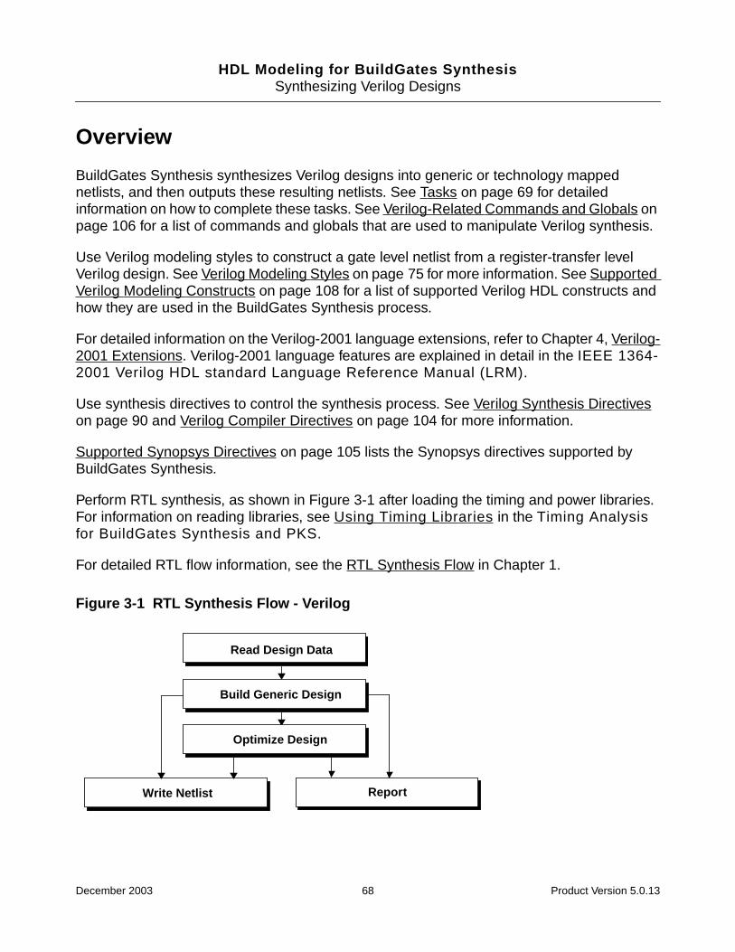
HDL Modeling for BuildGates SynthesisSynthesizing Verilog Designs
Overview
BuildGates Synthesis synthesizes Verilog designs into generic or technology mappednetlists, and then outputs these resulting netlists. See Tasks on page 69 for detailedinformation on how to complete these tasks. See Verilog-Related Commands and Globals onpage 106 for a list of commands and globals that are used to manipulate Verilog synthesis.
Use Verilog modeling styles to construct a gate level netlist from a register-transfer levelVerilog design. See Verilog Modeling Styles on page 75 for more information. See SupportedVerilog Modeling Constructs on page 108 for a list of supported Verilog HDL constructs andhow they are used in the BuildGates Synthesis process.
For detailed information on the Verilog-2001 language extensions, refer to Chapter 4, Verilog-2001 Extensions. Verilog-2001 language features are explained in detail in the IEEE 1364-2001 Verilog HDL standard Language Reference Manual (LRM).
Use synthesis directives to control the synthesis process. See Verilog Synthesis Directiveson page 90 and Verilog Compiler Directives on page 104 for more information.
Supported Synopsys Directives on page 105 lists the Synopsys directives supported byBuildGates Synthesis.
Perform RTL synthesis, as shown in Figure 3-1 after loading the timing and power libraries.For information on reading libraries, see Using Timing Libraries in the Timing Analysisfor BuildGates Synthesis and PKS.
For detailed RTL flow information, see the RTL Synthesis Flow in Chapter 1.
Figure 3-1 RTL Synthesis Flow - Verilog
Read Design Data
ReportWrite Netlist
Build Generic Design
Optimize Design
December 2003 68 Product Version 5.0.13
HDL Modeling for BuildGates SynthesisSynthesizing Verilog Designs
Tasks
The Verilog synthesis flow describes the following tasks for synthesizing Verilog designs:
■ Read Design Data on page 69
■ Build Generic Design on page 72
■ Write Netlist on page 72
For details about command arguments, see the Command Reference for BuildGatesSynthesis and PKS. For information on how to model Verilog designs see Verilog ModelingStyles on page 75.
Read Design Data
The first step in RTL synthesis is to read in the HDL design. The design data is read in usingthe Ambit Database (ADB), Electronic Design Interchange Format (EDIF), Verilog, or theVHDL format.
This section describes the data read in using the Verilog format. A design is read in a bottom-up or a top-down fashion.
Before reading in the designs, set the following globals described in the following sections.
December 2003 69 Product Version 5.0.13
HDL Modeling for BuildGates SynthesisSynthesizing Verilog Designs
Switching between Verilog-1995, Verilog-2001, and Verilog-DP
➤ Specify the Verilog version used to read Verilog designs:
set_global hdl_verilog_read_version { 1995 | 2001 | dp }
Default: 2001
This global ensures that only Verilog files that conform to the appropriate Verilogstandard are parsed successfully.
Verilog-DP is an upwardly compatible, proprietary extension to Verilog-2001 thatincludes a concise datapath description language to facilitate complex, highlyparameterized datapath designs. See Datapath for BuildGates Synthesis andCadence PKS for more information on Verilog-DP extensions
Specifying the Naming Style of Object Names
➤ Specify if the naming style of input and output object names will be in Verilog, VHDL, orno naming style:
set_global naming_style {vhdl | verilog | none}
Use the find command to get the names of input and object names.
Reading and Storing Verilog Modules as Components into an AmbitWare Library
➤ Use the read_verilog command to read in Verilog design files, and use the-aware_library option to store Verilog modules as components in a specifiedAmbitWare library:
read_verilog [-aware_library aware_libname] verilog_filename
For example, the following command reads three Verilog designs into the AmbitWarelibrary ZM122200.
read_verilog -aware_library ZM122200 zm_des1.v zm_des2.v zm_des3.v
For more information on AmbitWare libraries see Appendix A, “AmbitWare,”.
Follow the read_verilog command with the do_build_generic command before usingconstraint or optimization commands.
December 2003 70 Product Version 5.0.13

HDL Modeling for BuildGates SynthesisSynthesizing Verilog Designs
Creating a Verilog Netlist Directly for Structural Constructs
➤ Use the read_verilog -structural command to create a netlist for Verilog designsthat contain only structural constructs (module and gate instances and simpleassignments).
read_verilog [-structural] verilog_filenames
For example, the following command reads netlist.v and runs thedo_build_generic command:
read_verilog -structural netlist.v
Multiple file names are separated by blank spaces.
The -structural option does not support full RTL. It only handles the structural subsetof Verilog, that is, module and gate instances, concurrent assignment statements, andsimple expressions (references to nets, bit-selects and part-selects of nets,concatenations of nets, and the unary (~) operator.
Passing Arguments to the Verilog Preprocessor (VPP)
Pass arguments to the read_verilog command, such as the search path, using thefollowing global:
set_global hdl_verilog_vpp_arg
If this variable is set to -I/home/rtl, the read_verilog command searches for Verilogfiles in /home/rtl.
Getting HDL File Names, Hierarchy, and Top Level Design Names
You can use the get_hdl command after reading the HDL files into BuildGates Synthesiswithout having to first generate a generic netlist. See Querying the HDL Design Pool onpage 33 for information on how to use these commands.
■ Using the get_hdl_top_level Command on page 35
■ Using the get_hdl_hierarchy Command on page 35
■ Using the get_hdl_type Command on page 36
■ Using the get_hdl_file Command on page 36
December 2003 71 Product Version 5.0.13

HDL Modeling for BuildGates SynthesisSynthesizing Verilog Designs
Build Generic Design
➤ Use the do_build_generic command to transform the Verilog design into ahierarchical, gate-level netlist consisting of technology-independent logic gates:
do_build_generic
Follow these guidelines when building a generic design:
■ Issue the do_build_generic command after specifying the source Verilog files for theinitial design database and before using the do_optimize command. Write thegenerated netlist in Verilog with the write_verilog command. Load the generatednetlist for optimization and analysis using the read_verilog command.
■ By default, the do_build_generic command treats all procedural (initial andalways) blocks as part of the module in which they appear without any hierarchy. Whengrouping is specified with the -group_all_processes,-group_named_processes, or -group_process option, a new level of hierarchy iscreated to represent each selected block.
■ Use the do_build_generic -module option to generate netlists for selected modulesin the design hierarchy.
Write Netlist
Specifying the Maximum Line Length for Writing Out Verilog Netlist in Files
➤ Use the following global variable to specify the line length for writing out a Verilog netlistin a file:
set_global hdl_verilog_out_columns integer
Default: 80
Set the global hdl_write_multi_line_port_maps to false to ignore the limit.
Writing Out Compact Files for Verilog Netlist Output
➤ Set the following global to true to write out compact files for the Verilog netlist output:
set_global hdl_verilog_out_compact { true | false }
Default: true
The compact files have multiple statements on one line. If the files are unreadable, set thevariable to false so only one statement is written per line.
December 2003 72 Product Version 5.0.13
HDL Modeling for BuildGates SynthesisSynthesizing Verilog Designs
Writing Declarations for Implicit Wires
➤ Set the following global to true to write declarations for implicit wires:
set_global hdl_verilog_out_declare_implicit_wires { true | false }
Default: false
Note: Implicit wires in Verilog do not require a declaration.
Writing Primitive Verilog Operators Instead of ATL Equivalent Components
➤ Set the following global to true to write primitive Verilog operators instead of the ATLequivalent components:
set_global hdl_verilog_out_prim { true | false }
Default: true
Keeping Track of the RTL Source Code
➤ Set the following global to true to keep track of the RTL source code:
set_global hdl_verilog_out_source_track { true | false }
Default: false
Selecting the Netlisting Style for Unconnected Instance Pins
➤ Use the following global variables to select the netlisting style for unconnected instancepins:
set_global hdl_verilog_out_unconnected_style { none | partial | full }
Default: none
Specifying Constant Signals as Supply Signals
➤ Set the following global variable to true to specify that constant signals (1 or 0) will bedeclared as supply signals (supply1 or supply0).
set_global hdl_verilog_out_use_supply { true | false }
Default: false
December 2003 73 Product Version 5.0.13

HDL Modeling for BuildGates SynthesisSynthesizing Verilog Designs
Writing out Modules in Top-Down or Bottom-Up Order
➤ Use the following global variables to control whether Verilog netlists write out modules intop-down or bottom-up order:
set_global hdl_write_top_down {true | false}
Default: false
Specifies whether the design hierarchy should be written out in a top-down or bottom-upfashion. When the global is set to true, higher-level modules precede the lower-levelmodules in the netlist. When the global is set to false, lower-level modules are writtenout prior to modules that instantiate them.
Writing a Verilog Netlist
➤ Use the write_verilog command to write out a Verilog netlist:
write_verilog [-hierarchical] [-equation] verilog_file_name
For example, the following saves the hierarchical netlist in the file counter.v.net:
write_verilog -hierarchy counter.v.net
Note: If assign statements exist in the output, use the set_globalfix_multiport_nets command.
Follow these guidelines when writing out a Verilog netlist:
■ The write_verilog command writes out the netlist stored in the database in Verilog.The netlist is generated by the do_build_generic or the do_optimize command.
■ If a netlist is written out after using the do_optimize command, then it containsinstances of cells in the target technology library. Verify the netlist through simulationusing a Verilog library from the target technology.
December 2003 74 Product Version 5.0.13
HDL Modeling for BuildGates SynthesisSynthesizing Verilog Designs
Additional Information
■ Verilog Modeling Styles on page 75
■ Verilog Synthesis Directives on page 90
■ Verilog Compiler Directives on page 104
■ Operator Merging Directive on page 103
■ Supported Synopsys Directives on page 105
■ Verilog-Related Commands and Globals on page 106
■ Supported Verilog Modeling Constructs on page 108
Verilog Modeling Styles
See Supported Verilog Modeling Constructs on page 108 for a complete listing of supportedand unsupported Verilog HDL constructs. This section includes the following information:
■ Modeling Combinational Logic on page 76
■ Inferring a Register on page 78
■ Using case Statements for Multi-Way Branching on page 83
■ Using a for Statement to Describe Repetitive Operations on page 89
December 2003 75 Product Version 5.0.13
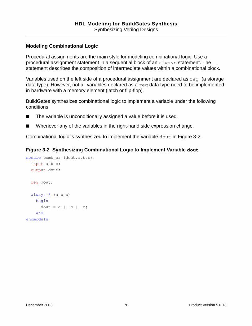
HDL Modeling for BuildGates SynthesisSynthesizing Verilog Designs
Modeling Combinational Logic
Procedural assignments are the main style for modeling combinational logic. Use aprocedural assignment statement in a sequential block of an always statement. Thestatement describes the composition of intermediate values within a combinational block.
Variables used on the left side of a procedural assignment are declared as reg (a storagedata type). However, not all variables declared as a reg data type need to be implementedin hardware with a memory element (latch or flip-flop).
BuildGates synthesizes combinational logic to implement a variable under the followingconditions:
■ The variable is unconditionally assigned a value before it is used.
■ Whenever any of the variables in the right-hand side expression change.
Combinational logic is synthesized to implement the variable dout in Figure 3-2.
Figure 3-2 Synthesizing Combinational Logic to Implement Variable dout
module comb_or (dout,a,b,c);
input a,b,c;
output dout;
reg dout;
always @ (a,b,c)
begin
dout = a || b || c;
end
endmodule
December 2003 76 Product Version 5.0.13

HDL Modeling for BuildGates SynthesisSynthesizing Verilog Designs
■ The variable is conditionally assigned a value under all possible conditions whenever anyof the variables in the right side expression change, as shown in Figure 3-3.
Figure 3-3 Synthesizing Combinational Logic to Implement Signal zmodule comb_mux (dout,sel,a,b,);
input sel,a,b;
output dout;
reg dout;
always @ (a,b,sel)
begin
if (sel)
dout = a;
else
dout = b;
end
endmodule
December 2003 77 Product Version 5.0.13
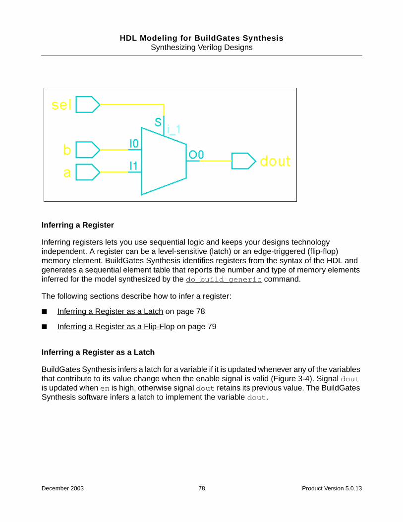
HDL Modeling for BuildGates SynthesisSynthesizing Verilog Designs
Inferring a Register
Inferring registers lets you use sequential logic and keeps your designs technologyindependent. A register can be a level-sensitive (latch) or an edge-triggered (flip-flop)memory element. BuildGates Synthesis identifies registers from the syntax of the HDL andgenerates a sequential element table that reports the number and type of memory elementsinferred for the model synthesized by the do_build_generic command.
The following sections describe how to infer a register:
■ Inferring a Register as a Latch on page 78
■ Inferring a Register as a Flip-Flop on page 79
Inferring a Register as a Latch
BuildGates Synthesis infers a latch for a variable if it is updated whenever any of the variablesthat contribute to its value change when the enable signal is valid (Figure 3-4). Signal doutis updated when en is high, otherwise signal dout retains its previous value. The BuildGatesSynthesis software infers a latch to implement the variable dout.
December 2003 78 Product Version 5.0.13
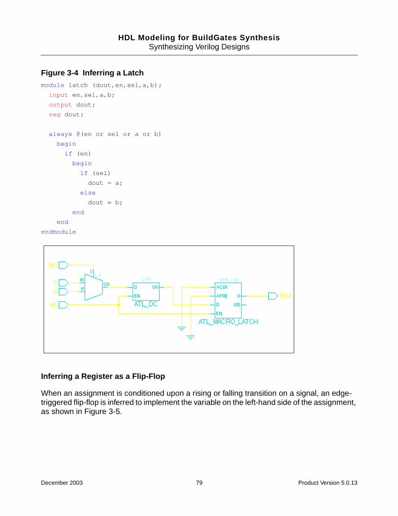
HDL Modeling for BuildGates SynthesisSynthesizing Verilog Designs
Figure 3-4 Inferring a Latchmodule latch (dout,en,sel,a,b);
input en,sel,a,b;
output dout;
reg dout;
always @(en or sel or a or b)
begin
if (en)
begin
if (sel)
dout = a;
else
dout = b;
end
end
endmodule
Inferring a Register as a Flip-Flop
When an assignment is conditioned upon a rising or falling transition on a signal, an edge-triggered flip-flop is inferred to implement the variable on the left-hand side of the assignment,as shown in Figure 3-5.
December 2003 79 Product Version 5.0.13

HDL Modeling for BuildGates SynthesisSynthesizing Verilog Designs
Figure 3-5 Inferring a Flip-Flopmodule sync_flop (clk, din, dout);
input clk;
input din;
output dout;
reg dout;
always @(posedge clk)
begin
dout <= din;
end
endmodule
A flip-flop with asynchronous operation is inferred, as shown in Example 3-1, when anassignment is made without being dependent on the clock edge. The asynchronous behavioris implemented in hardware through asynchronous set and reset pins on a flip-flop, as shownin Figure 3-6.
December 2003 80 Product Version 5.0.13

HDL Modeling for BuildGates SynthesisSynthesizing Verilog Designs
Example 3-1 Modeling an Asynchronous Operation On a Flip-Flopmodule ff_ar(dout,clk,rst,en,sel,a,b);
input clk,rst,en,sel,a,b;
output dout;
reg dout;
always @(posedge clk or posedge rst) begin
if (rst)
dout = 1’b0;
else if (en) begin
if (sel)
dout = a;
else
dout = b;
end
end
endmodule
Figure 3-6 Schematic Representation of an Asynchronous Operation On a Flip-Flop
December 2003 81 Product Version 5.0.13

HDL Modeling for BuildGates SynthesisSynthesizing Verilog Designs
The always block is triggered when a rising edge is detected on clk or a falling edge onreset. If reset is active low, then the event in the sensitivity list and the condition in the ifstatement should be negated as shown in Example 3-2.
Example 3-2 Negating the Condition in an if Statementmodule ff_ar(dout,clk,rst,en,sel,a,b);
input clk,rst,en,sel,a,b;
output dout;
reg dout;
always @(posedge clk or negedge rst) begin
if (~rst)
dout = 1’b0;
else if (en) begin
if (sel)
dout = a;
else
dout = b;
end
end
endmodule
Figure 3-7 shows the schematic representation of negating the condition.
December 2003 82 Product Version 5.0.13

HDL Modeling for BuildGates SynthesisSynthesizing Verilog Designs
Figure 3-7 Schematic Representation of Negating the Condition in an if Statement
Using case Statements for Multi-Way Branching
Use a case statement for multi-way branching in a functional description. When a casestatement is used as a decoder to assign one of several different values to a variable, theensuing logic is implemented as combinational or sequential logic based on whether thevariable is assigned a value in all branches of the case statement. BuildGates Synthesisautomatically determines whether a case statement is full or parallel. A casestatement is full if all possible case items are specified. A case statement is parallel ifnone of the case statement conditions overlap and are mutually exclusive. If automaticdetermination of full or parallel case is not possible, use the full and parallelcase directives (see Full Case Directive on page 94, and Parallel Case Directive onpage 95).
The following sections describe the impact on synthesis for different use models and types ofcase statements.
Using an Incomplete case Statement to Infer a Latch
When a case statement does not specify all possible case condition values, a latch isinferred. If BuildGates determines that the case is not full, it uses a latch to implement astate transition table as shown in Example 3-3.
December 2003 83 Product Version 5.0.13

HDL Modeling for BuildGates SynthesisSynthesizing Verilog Designs
Example 3-3 Modeling a State Transition Table to Infer a Latchmodule case_latch(dout,sel,a,b,c);
input [1:0] sel;
input a,b,c;
output dout;
reg dout;
always @(a,b,c,sel) begin
case (sel)
2’b00 : dout = a;
2’b01 : dout = b;
2’b10 : dout = c;
endcase
end
endmodule
Using an Fully Specified case Statement to Prevent a Latch
Use one of the following methods to assign a default value to next_state:
■ Assign the next_state variable an unconditional value, then use a case statement tomodify it, as shown in the Example 3-4.
Example 3-4 Preventing a Latch by Assigning a Default Value to next_state
module case_latch(dout,sel,a,b,c);
input [1:0] sel;
input a,b,c;
output dout;
reg dout;
always @(a,b,c,sel) begin
dout = 1’b0;
case (sel)
2’b00 : dout = a;
2’b01 : dout = b;
2’b10 : dout = c;
endcase
end
endmodule
December 2003 84 Product Version 5.0.13

HDL Modeling for BuildGates SynthesisSynthesizing Verilog Designs
Use the default case in the case statement to capture all the remaining cases where the nextstate variable is assigned a value, as shown in Example 3-5.
Example 3-5 Preventing a Latch by Using the Default case in the case Statementmodule case_latch(dout,sel,a,b,c);
input [1:0] sel;
input a,b,c;
output dout;
reg dout;
always @(a,b,c,sel) begin
dout = 1’b0;
case (sel)
2’b00 : dout = a;
2’b01 : dout = b;
2’b10 : dout = c;
default : dout = 1‘b0;
endcase
end
endmodule
You can also use the full case synthesis directive as discussed in Full CaseDirective on page 94. The simulation results between functional and gate level models maymismatch if this synthesis directive is used.
Using casez and casex Statements to Treat x, z and ? Like Don’t Cares
Use casex and casez statements to treat x, z and ? values like don’t care conditions whencomparing for the matching case. These statements are treated like case statements withthe following differences:
■ Use a casez statement to treat z and ? as a don’t care condition.
■ Use a casex statement to treat x, z and ? as a don’t care condition.
December 2003 85 Product Version 5.0.13

HDL Modeling for BuildGates SynthesisSynthesizing Verilog Designs
Example 3-6 shows a casez statement using don’t care conditions to mask three of thefour bits in the decoding select line (input sel).
Example 3-6 Using Don’t Care Conditions in a casez Statementmodule case_z(dout,sel,a,b,c,d,e);
input [3:0] sel;
input a,b,c,d,e;
output dout;
reg dout;
always @(a,b,c,d,e,sel) begin
casez (sel)
4’b0000 : dout = a;
4’b???1 : dout = b;
4’b??1? : dout = c;
4’b?1?? : dout = d;
4’b1??? : dout = e;
endcase
end
endmodule
In the example, dout is set to b if sel[0] = 1, regardless of the values of sel[3], sel[2]and sel[1]; dout is set to c only if sel[0] = 0 and sel[1] = 1, regardless of the valuesof sel[3] and se[2]. Figure 3-8 shows the schematic representation.
December 2003 86 Product Version 5.0.13

HDL Modeling for BuildGates SynthesisSynthesizing Verilog Designs
Figure 3-8 Schematic Representation of Using Don’t Care Conditions in a casezStatement
➤ Enter the read_verilog and do_build_generic commands to view a report of thecasez statement as shown in Example 3-7.
Example 3-7 Report of the casex Statementbg_shell[1]>read_verilog case_z.v
bg_shell[2]>do_build_generic
Info: Processing design ’case_z’ <CDFG-303>.
Statistics for case statements in module ’case_z’ (File case_z.v) <CDFG-800>.
+----------------------------------------+
| Case Statistics Table |
|----------------------------------------|
| Line | Type | Full | Parallel |
|---------+---------+---------+----------|
| 8 | casez | AUTO | NO |
+----------------------------------------+
Finished processing module: ’case_z’ <MODGEN-110>.
December 2003 87 Product Version 5.0.13
HDL Modeling for BuildGates SynthesisSynthesizing Verilog Designs
One or more case items overlap (not parallel) and a priority encoder is required to implementthe equivalent hardware.
Example 3-8 shows a casex statement using don’t care conditions in the same manner asthe casez statement. The difference between the two models is that the casex statementmasks three bits of the select line that would match x, z, or ?, but the casez statement willnot mask x in the select line.
Example 3-8 Using Don’t Care Conditions in a casex Statementmodule case_x(dout,sel,a,b,c,d,e);
input [3:0] sel;
input a,b,c,d,e;
output dout;
reg dout;
always @(a,b,c,d,e,sel) begin
casez (sel)
4’bxxx1 : dout = a;
4’bxx1x : dout = b;
4’bx1xx : dout = c;
4’b1xxx : dout = d;
default : dout = e;
endcase
end
endmodule
➤ Enter the read_verilog and do_build_generic commands to view a report of thecasez statement as shown in Example 3-9.
Example 3-9 Report of the casex Statementbg_shell[1]>read_verilog casex.v
bg_shell[2]>do_build_generic
Info: Processing design ’case_x’ <CDFG-303>.
Statistics for case statements in module ’case_x’ (File casex.v) <CDFG-800>.
+----------------------------------------+
| Case Statistics Table |
|----------------------------------------|
| Line | Type | Full | Parallel |
|---------+---------+---------+----------|
| 8 | casex | AUTO | NO |
+----------------------------------------+
December 2003 88 Product Version 5.0.13
HDL Modeling for BuildGates SynthesisSynthesizing Verilog Designs
Finished processing module: ’case_x’ <MODGEN-110>.
Info: Setting ’case_x’ as the top of the design hierarchy <FNP-704>.
Info: Setting ’case_x’ as the default top timing module <FNP-705>.
Using a for Statement to Describe Repetitive Operations
Use the for statement to describe repetitive operations as shown in Example 3-10 where iis declared as an integer and dout is a 4-bit register.
Example 3-10 Using the for Statement to Describe Repetitive Operationsmodule for_loop(dout,sel,a,b,)
input sel;
input [3:0] a,b;
output [3:0] dout;
reg [3:0] dout;
integer i;
always @(a,b,sel) begin
for (i=0; i<=3; i=i+1) begin
if (sel)
dout[i] = a[3-i];
else
dout[i] = b[i];
end
end
endmoudle
The for statement is expanded to repeat the operations over the range of the index.
Supported Forms of the for Statement in Verilogfor (index = low; index < high; index = index+step)
for (index = low; index <= high; index = index+step)
for (index = high; index > low; index = index-step)
for (index = high; index >= low; index = index-step)
The index is declared as an integer or a reg; high, low and step are integers, andhigh must be greater than or equal to low.
Note: High, low and step must evaluate to constant numbers at compile time. An errormessage is generated if one of them does not evaluate to a constant number.
December 2003 89 Product Version 5.0.13
HDL Modeling for BuildGates SynthesisSynthesizing Verilog Designs
A for statement can be nested inside another for statement, but it cannot contain any formof timing control or event control. Therefore, the following usage of the for statement isillegal:
for (i = 0; i <= 7; i = i + 1)
@(posedge clk) out[7-i] <= in[i] ;
Verilog Synthesis Directives
Synthesis directives are specially-formatted comments. Do not confuse these comments withVerilog HDL compiler directives that begin with ‘.
BuildGates Synthesis supports the following two forms of Verilog synthesis directives:
■ Short comments that terminate at the end of the line:
// ambit synthesis directive_name
■ Long comments that extend beyond one line:
/* ambit synthesis directive_name */
Each comment begins with the words ambit synthesis.
Note: When using a comment for specifying a synthesis directive, that comment should notcontain any extra characters other than what is necessary for the synthesis directive.
■ Synthesis On and Off Directives on page 91
■ Architecture Selection Directive on page 92
■ case Statement Directives on page 93
■ Module Template Directive on page 96
■ Function and Task Mapping Directives on page 96
■ Set and Reset Synthesis Directives on page 98
■ Block Directives on page 100
■ Signal Directives on page 101
■ Signals in a Block Directive on page 102
■ Operator Merging Directive on page 103
December 2003 90 Product Version 5.0.13
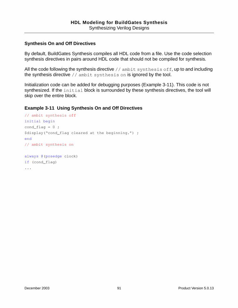
HDL Modeling for BuildGates SynthesisSynthesizing Verilog Designs
Synthesis On and Off Directives
By default, BuildGates Synthesis compiles all HDL code from a file. Use the code selectionsynthesis directives in pairs around HDL code that should not be compiled for synthesis.
All the code following the synthesis directive // ambit synthesis off, up to and includingthe synthesis directive // ambit synthesis on is ignored by the tool.
Initialization code can be added for debugging purposes (Example 3-11). This code is notsynthesized. If the initial block is surrounded by these synthesis directives, the tool willskip over the entire block.
Example 3-11 Using Synthesis On and Off Directives// ambit synthesis off
initial begin
cond_flag = 0 ;
$display(“cond_flag cleared at the beginning.”) ;
end
// ambit synthesis on
always @(posedge clock)
if (cond_flag)
...
December 2003 91 Product Version 5.0.13
HDL Modeling for BuildGates SynthesisSynthesizing Verilog Designs
Architecture Selection Directive
Use this directive to select different types of architectures for arithmetic and comparator(relational) operators. The available architectures are based on whether you have purchasedthe Datapath license with BuildGates Synthesis.
For information on Datapath, refer to the Datapath for BuildGates Synthesis andCadence PKS.
The standard BuildGates Synthesis software without Datapath contains the following finaladder architectures:
■ cla (carry lookahead)
■ ripple (ripple carry)
The BuildGates Synthesis software with Datapath contains the following final adder andmultiplier encoding architectures:
Datapath final adder architectures:
■ fcla (fast carry lookahead)
■ cla (carry lookahead)
■ csel (carry select)
■ ripple (ripple carry)
Datapath multiplier encoding architectures:
■ non-booth
■ booth
For Verilog, specify the architecture selection directive immediately after the operator asshown in the following example.
Example 3-12 Specifying the Architecture Selection Directiveassign x = a + /* ambit synthesis architecture = ripple */ b
If there are multiple operators in the expression, place the directive immediately following thedesired operator, as shown in Example 3-13.
December 2003 92 Product Version 5.0.13
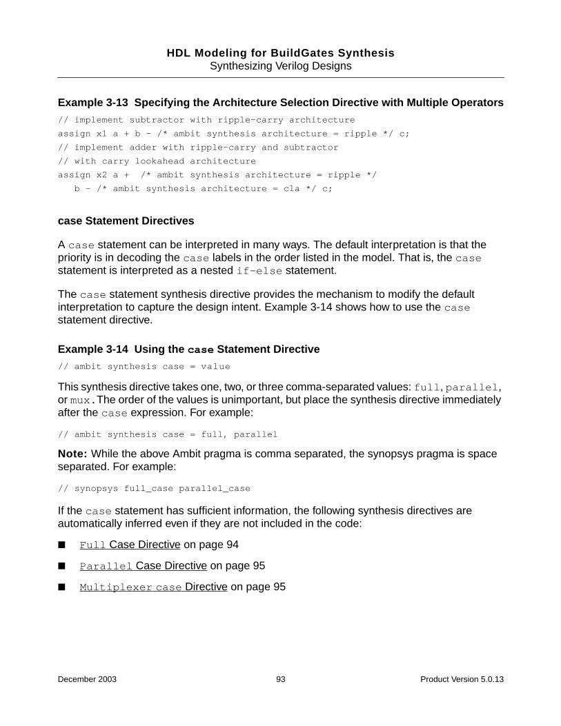
HDL Modeling for BuildGates SynthesisSynthesizing Verilog Designs
Example 3-13 Specifying the Architecture Selection Directive with Multiple Operators// implement subtractor with ripple-carry architecture
assign x1 a + b - /* ambit synthesis architecture = ripple */ c;
// implement adder with ripple-carry and subtractor
// with carry lookahead architecture
assign x2 a + /* ambit synthesis architecture = ripple */
b - /* ambit synthesis architecture = cla */ c;
case Statement Directives
A case statement can be interpreted in many ways. The default interpretation is that thepriority is in decoding the case labels in the order listed in the model. That is, the casestatement is interpreted as a nested if-else statement.
The case statement synthesis directive provides the mechanism to modify the defaultinterpretation to capture the design intent. Example 3-14 shows how to use the casestatement directive.
Example 3-14 Using the case Statement Directive// ambit synthesis case = value
This synthesis directive takes one, two, or three comma-separated values: full, parallel,or mux.The order of the values is unimportant, but place the synthesis directive immediatelyafter the case expression. For example:
// ambit synthesis case = full, parallel
Note: While the above Ambit pragma is comma separated, the synopsys pragma is spaceseparated. For example:
// synopsys full_case parallel_case
If the case statement has sufficient information, the following synthesis directives areautomatically inferred even if they are not included in the code:
■ Full Case Directive on page 94
■ Parallel Case Directive on page 95
■ Multiplexer case Directive on page 95
December 2003 93 Product Version 5.0.13
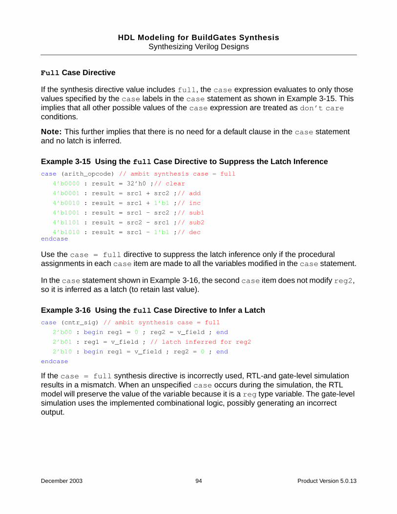
HDL Modeling for BuildGates SynthesisSynthesizing Verilog Designs
Full Case Directive
If the synthesis directive value includes full, the case expression evaluates to only thosevalues specified by the case labels in the case statement as shown in Example 3-15. Thisimplies that all other possible values of the case expression are treated as don’t careconditions.
Note: This further implies that there is no need for a default clause in the case statementand no latch is inferred.
Example 3-15 Using the full Case Directive to Suppress the Latch Inferencecase (arith_opcode) // ambit synthesis case = full
4’b0000 : result = 32’h0 ;// clear
4’b0001 : result = src1 + src2 ;// add
4’b0010 : result = src1 + 1’b1 ;// inc
4’b1001 : result = src1 - src2 ;// sub1
4’b1101 : result = src2 - src1 ;// sub2
4’b1010 : result = src1 - 1’b1 ;// decendcase
Use the case = full directive to suppress the latch inference only if the proceduralassignments in each case item are made to all the variables modified in the case statement.
In the case statement shown in Example 3-16, the second case item does not modify reg2,so it is inferred as a latch (to retain last value).
Example 3-16 Using the full Case Directive to Infer a Latchcase (cntr_sig) // ambit synthesis case = full
2’b00 : begin reg1 = 0 ; reg2 = v_field ; end
2’b01 : reg1 = v_field ; // latch inferred for reg2
2’b10 : begin reg1 = v_field ; reg2 = 0 ; end
endcase
If the case = full synthesis directive is incorrectly used, RTL-and gate-level simulationresults in a mismatch. When an unspecified case occurs during the simulation, the RTLmodel will preserve the value of the variable because it is a reg type variable. The gate-levelsimulation uses the implemented combinational logic, possibly generating an incorrectoutput.
December 2003 94 Product Version 5.0.13
HDL Modeling for BuildGates SynthesisSynthesizing Verilog Designs
Parallel Case Directive
If the synthesis directive value includes parallel, all the case labels have equal priority ofmatching the case expression. The optimizer uses this information to avoid building adecoder to decode for 2n alternatives where n is the size (in bits) of the case expression. Theoptimizer builds a parallel decoding logic instead of priority encoder logic to drive the selectlines for the multiplexer. Example 3-17 shows how to use the parallel case directive.
Example 3-17 Using the parallel Case Directivecase (1’b1) // ambit synthesis case = parallel
cc[0] : cntr = 0 ;
cc[1] : cntr = data_in ;
cc[2] : cntr = cntr - 1 ;
cc[3] : cntr = cntr + 1 ;
endcase
During simulation, if the case expression matches more than one case label, the logiccorresponds to each case label. This causes the results to differ between RTL simulation andnetlist simulation. This occurs if you use casex or casez statements to mask certaincombinations. The RTL simulation performs the procedural assignment corresponding to thefirst case label match, whereas the gate-level simulation enables the logic for all the matchingcase labels. Therefore, ensure that only one case label is matched in the case statementbefore using the parallel case directive. Example 3-17 shows logic to guarantee that onlyone of the four bits of cc is high at any given time.
Multiplexer case Directive
If the synthesis directive value includes mux, the case statement indicates that the decodinglogic for loading the value in the register is always a multiplexer instead of a priority encoder(implies full and parallel) as shown in Example 3-18.
December 2003 95 Product Version 5.0.13

HDL Modeling for BuildGates SynthesisSynthesizing Verilog Designs
Example 3-18 Using the Multiplexer case Directivealways @ (sel) begin
case (sel) //ambit synthesis case = mux
3’b000 : out = d1;
3’b001 : out = d2;
3’b010 : out = d3;
3’b011 : out = d4;
3’b100 : out = d5;
3’b111 : out = d6;
endcase
end
Module Template Directive
The template directive on a module indicates that the template module is not to besynthesized except in the context of an instantiation as shown in Example 3-19.
Example 3-19 Using the Module Template Directivemodule foo(din,dout); // ambit synthesis template
parameter width := 64;
input [width-1:0] din;
output [width-1:0] dout;
...
endmodule
Function and Task Mapping Directives
Use the map_to_module directive to specify that the behavior of a task or function is to beimplemented using a given module or cell. Use the return_port_name directive to map afunction’s return value onto the given module port.
Use the map_to_module directive to specify that any call to the given task or function is tobe internally mapped to an instantiation of the specified module. The statements in the taskor function body are therefore ignored.
Arguments to the task or function are mapped by name onto ports in the module.
In Example 3-20, task t is mapped to module flop. The arguments of t are associated byname with the ports of module flop. So the task argument q is associated with port q ofmodule flop.
December 2003 96 Product Version 5.0.13
HDL Modeling for BuildGates SynthesisSynthesizing Verilog Designs
A call to t like this:
t(a, b, c);
is equivalent to an instantiation of module flop:
flop u1(.q(a), .d(b), .clk(c));
Example 3-20 Using the map_to_module Directive
If a module has the interface:
module flop (q, d, clk);
then a task can be mapped to this module as follows:
task t;
//ambit synthesis map_to_module flop
output q;
input d, clk;
q = d;
endtask
Use the return_port_name directive with functions that use the map_to_moduledirective. The directive specifies that the return value for the function call is given by the outputport of the mapped-to module, as shown in Example 3-21.
Example 3-21 Using the return_port_name with the map_to_module Directive
A cell MUX has the following ports:
module MUX (q, d0, d1, sel);
Function f can be mapped to cell MUX as follows:
function f;
input d0, d1, sel;
// ambit synthesis map_to_module MUX
// ambit synthesis return_port_name q
f = sel ? d0 : d1;
endfunction
Then input d0 of function f is mapped to port d0 of cell MUX, and so on. Port q of MUX is usedto provide the return value for the function. As a result, the following two statements areequivalent:
assign q = f (d0, d1, sel);
...
MUX u1 (.q(q), .d0 (d0), .d1 (d1), .sel (sel));
December 2003 97 Product Version 5.0.13

HDL Modeling for BuildGates SynthesisSynthesizing Verilog Designs
Set and Reset Synthesis Directives
When the do_build_generic command infers a register from a HDL description, it alsoinfers set and reset control of the register and defines whether these controls aresynchronous or asynchronous.
Table 3-1 summarizes the condition in which the set and reset operation is inferred. Thisautomatic detection of the set and reset operation is always active, even when thesynthesis directives are not used. The synthesis directives express the preference to have theset and reset operations implemented using the set and reset pins on the storageelements.
Note: These directives only convey user preferences. They do not force the tool to honorthe directives. Therefore, in some scenarios the directives could be ignored if such anomission provides a better quality netlist. The behavior of the netlist is not affected. To forcethe tool to implement a specific flip-flop or latch, use the set_register_type command.
Table 3-1 Register Inference: set and reset Control
Example 3-22 shows how to implement synchronous set and reset logic for inferred flip-flops. Figure 3-9 provides the schematic representation of the logic.
Clock Flip-Flop Latch
Sync @(posedge clk) Not-Applicable
Async @(posedge clk or posedge set ornegedge reset)
@(data or enable or set or reset)
December 2003 98 Product Version 5.0.13
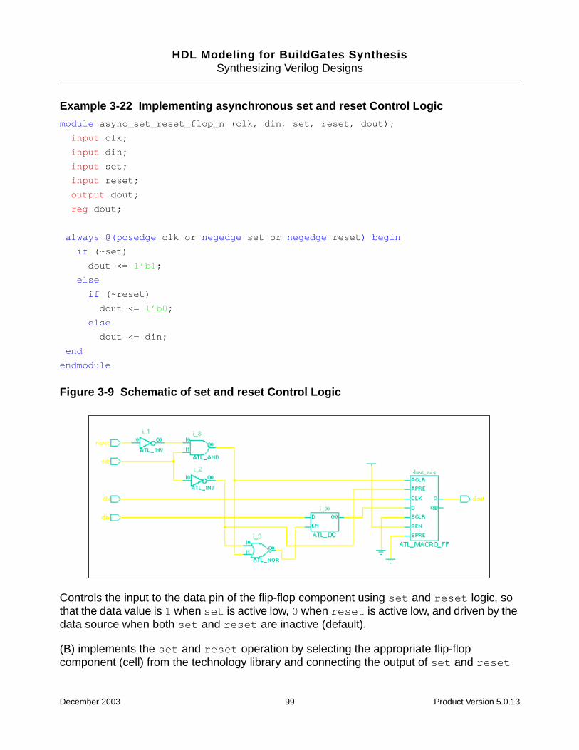
HDL Modeling for BuildGates SynthesisSynthesizing Verilog Designs
Example 3-22 Implementing asynchronous set and reset Control Logicmodule async_set_reset_flop_n (clk, din, set, reset, dout);
input clk;
input din;
input set;
input reset;
output dout;
reg dout;
always @(posedge clk or negedge set or negedge reset) begin
if (~set)
dout <= 1’b1;
else
if (~reset)
dout <= 1’b0;
else
dout <= din;
end
endmodule
Figure 3-9 Schematic of set and reset Control Logic
Controls the input to the data pin of the flip-flop component using set and reset logic, sothat the data value is 1 when set is active low, 0 when reset is active low, and driven by thedata source when both set and reset are inactive (default).
(B) implements the set and reset operation by selecting the appropriate flip-flopcomponent (cell) from the technology library and connecting the output of set and reset
December 2003 99 Product Version 5.0.13

HDL Modeling for BuildGates SynthesisSynthesizing Verilog Designs
logic directly to the set and reset pins of the component. The data pin of the component isdriven directly by the data source.
There are six synthesis directives to support the selection of set and reset logicimplementation at the block level or at the signal level for each register inferred. Thesesynthesis directives are advisory directives only. They do not force the optimizer to implementset and reset logic with one approach. Instead, they drive the selection of the componentfrom the technology library to provide the option for the optimizer. To force the optimizer toimplement a particular flip-flop or latch, use the set_register_type command.
Note: These directives only advise the tool of a user preference. The tool could ignore thesedirectives if a better netlist can be obtained with such an omission. However, these synthesisdirectives do not change the behavior of the netlist in any way. If the design is written withsynchronous control on a flip-flop, and the synthesis directive specifies asynchronousselection, the resulting implementation is synchronous. A warning message is issued if thesynthesis directive conflicts with the model.
Directives can always be viewed in the report that is generated after thedo_build_generic command is issued.
Block Directives
Specify the synthesis directive for block level set and reset signal selection as follows:
// ambit synthesis set_reset asynchronous blocks = block_name_list
// ambit synthesis set_reset synchronous blocks = block_name_list
These synthesis directives indicate that the set and reset control logic for the inferredregisters listed in named blocks listed should be connected to the asynchronous andsynchronous pins respectively.
The block_name_list is a comma-separated list of simple block names in string form(surrounded by quotes). Hierarchical block names are not supported.
Note: Use these directives inside a module with listed names and before the always block.It is an error to list an undefined block name.
December 2003 100 Product Version 5.0.13

HDL Modeling for BuildGates SynthesisSynthesizing Verilog Designs
Signal Directives
Specify the synthesis directives for signal level set and reset signal selection as follows:
// ambit synthesis set_reset asynchronous signals = signal_name_list
// ambit synthesis set_reset synchronous signals = signal_name_list
In Verilog, when set and reset control logic is inferred for a register, it is possible toselectively connect some of the signals directly to the set or reset pin of the componentand let the other signals propagate through logic onto the data pin.
The signal_name_list is a comma-separated list of signal names (surrounded byparentheses) in a module as shown in Example 3-23. Hierarchical signal names are notpermitted.
Note: These directives must be used inside a module and precede all always blocks. Donot list an undefined or an unused signal. Also, the signal directive must be specified in thesame declarative region as the signal being attributed.
Example 3-23 Using the set and reset Synchronous Signals Synthesis Directivemodule sync_sig_dff(out1, out2, clk, in, set1, set2, rst1, rst2);
output out1, out2;
input in, clk, set1, set2, rst1, rst2;
reg out1, out2;
//ambit synthesis set_reset synchronous signals="set1"
always @(posedge clk) begin
if (set1)
out1 <= 1;
else if (rst1)
out1 <= 0;
else out1 <= in;
end
always @(posedge clk) begin
if (set2)
out2 <= 1;
else if (rst2)
out2 <= 0;
else out2 <= in;
end
endmodule
December 2003 101 Product Version 5.0.13
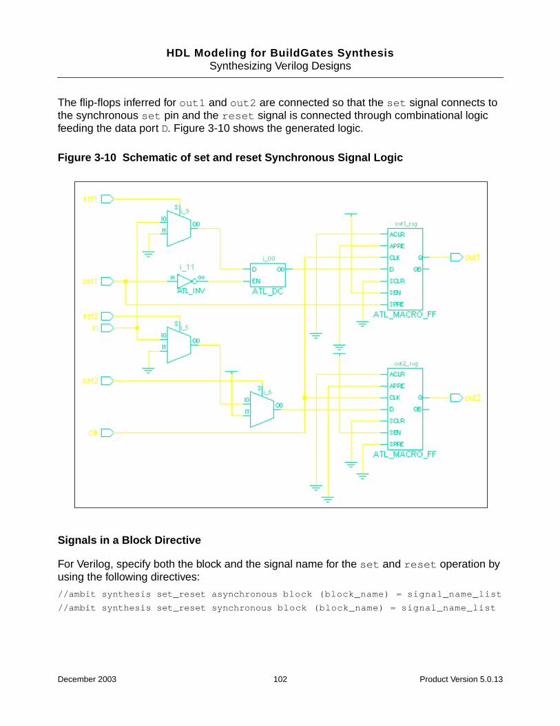
HDL Modeling for BuildGates SynthesisSynthesizing Verilog Designs
The flip-flops inferred for out1 and out2 are connected so that the set signal connects tothe synchronous set pin and the reset signal is connected through combinational logicfeeding the data port D. Figure 3-10 shows the generated logic.
Figure 3-10 Schematic of set and reset Synchronous Signal Logic
Signals in a Block Directive
For Verilog, specify both the block and the signal name for the set and reset operation byusing the following directives:
//ambit synthesis set_reset asynchronous block (block_name) = signal_name_list
//ambit synthesis set_reset synchronous block (block_name) = signal_name_list
December 2003 102 Product Version 5.0.13
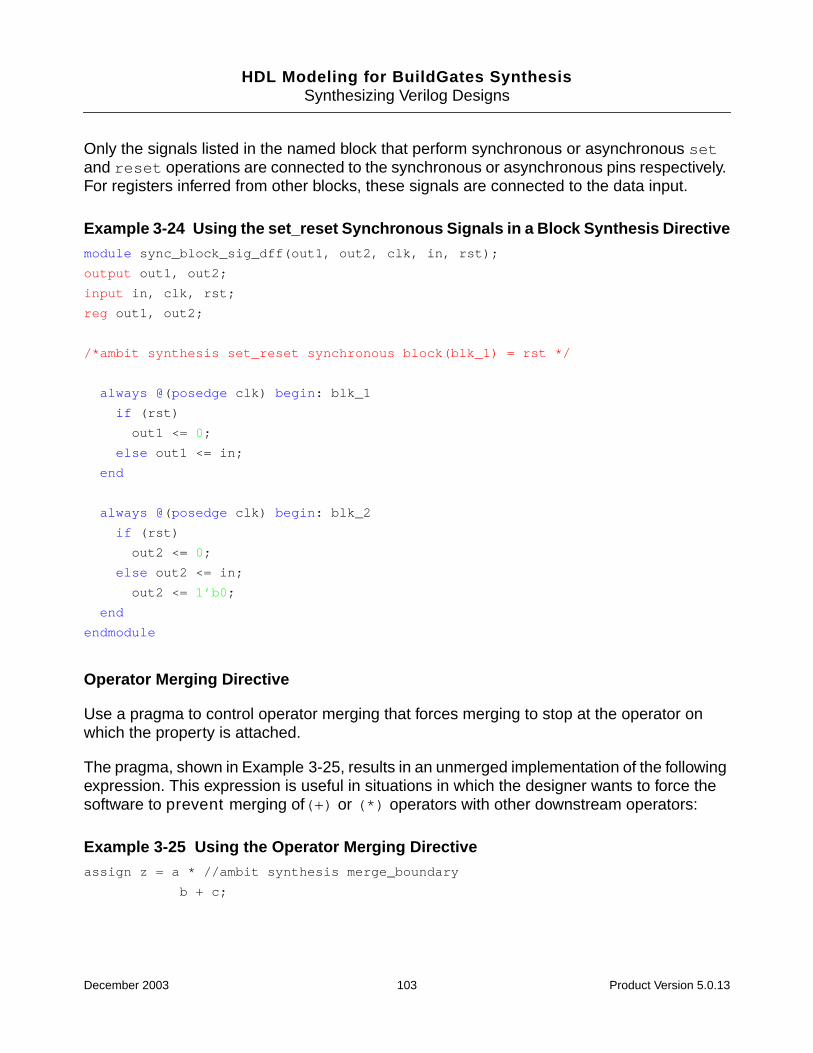
HDL Modeling for BuildGates SynthesisSynthesizing Verilog Designs
Only the signals listed in the named block that perform synchronous or asynchronous setand reset operations are connected to the synchronous or asynchronous pins respectively.For registers inferred from other blocks, these signals are connected to the data input.
Example 3-24 Using the set_reset Synchronous Signals in a Block Synthesis Directivemodule sync_block_sig_dff(out1, out2, clk, in, rst);
output out1, out2;
input in, clk, rst;
reg out1, out2;
/*ambit synthesis set_reset synchronous block(blk_1) = rst */
always @(posedge clk) begin: blk_1
if (rst)
out1 <= 0;
else out1 <= in;
end
always @(posedge clk) begin: blk_2
if (rst)
out2 <= 0;
else out2 <= in;
out2 <= 1’b0;
end
endmodule
Operator Merging Directive
Use a pragma to control operator merging that forces merging to stop at the operator onwhich the property is attached.
The pragma, shown in Example 3-25, results in an unmerged implementation of the followingexpression. This expression is useful in situations in which the designer wants to force thesoftware to prevent merging of(+) or (*) operators with other downstream operators:
Example 3-25 Using the Operator Merging Directiveassign z = a * //ambit synthesis merge_boundary
b + c;
December 2003 103 Product Version 5.0.13

HDL Modeling for BuildGates SynthesisSynthesizing Verilog Designs
Verilog Compiler Directives
The read_verilog command supports and interprets the following Verilog HDL compilerdirectives:
■ `define
■ `ifdef
■ `ifndef
■ `else
■ `elsif
■ `endif
■ `include
■ `undef
■ `default_nettype
■ `line
The read_verilog command also supports the following non-standard compiler directives,only if the global variable hdl_verilog_old_vpp is set to true. Support for these non-standard directives will be removed in future versions. Any other Verilog HDL compilerdirectives are ignored by the read_verilog command.
Non-Standard Verilog Compiler Directives
The following non-standard Verilog compiler directives are not supported:
■ ‘for
■ ‘if
■ ‘eval
■ ‘{}
December 2003 104 Product Version 5.0.13

HDL Modeling for BuildGates SynthesisSynthesizing Verilog Designs
Supported Synopsys Directives
Table 3-2 lists the correspondence of BuildGates Verilog directives to Synopsys directives.
Note: The Cadence Verilog directives supported by BuildGates are identical to the Synopsysdirectives. That is, for any Synopsys directive: // synopsys x y z, a Cadence directive issupported: // cadence x y z. BuildGates Synthesis directives begin with // ambitsynthesis.
See Datapath for BuildGates Synthesis and Cadence PKS for a list of Ambit-onlydatapath directives supported by BuildGates.
Table 3-2 Supported Verilog Synopsys Directives
Synopsys BuildGates
translate_off synthesis off
translate_on synthesis on
full_case case = full
parallel_case case = parallel
sync_set_reset set_reset synchronous signal
async_set_reset set_reset asynchronous signal
sync_set_reset_local set_reset synchronous block
async_set_reset_local set_reset asynchronous block
sync_set_reset_local_all set_reset synchronous blocks
async_set_reset_local_all set_reset asynchronous block
infer_mux case = mux
infer_mux block (xxx) = mux
state_vector state_vector xxx
template template
map_to_module map_to_module
return_port_name return_port_name
December 2003 105 Product Version 5.0.13
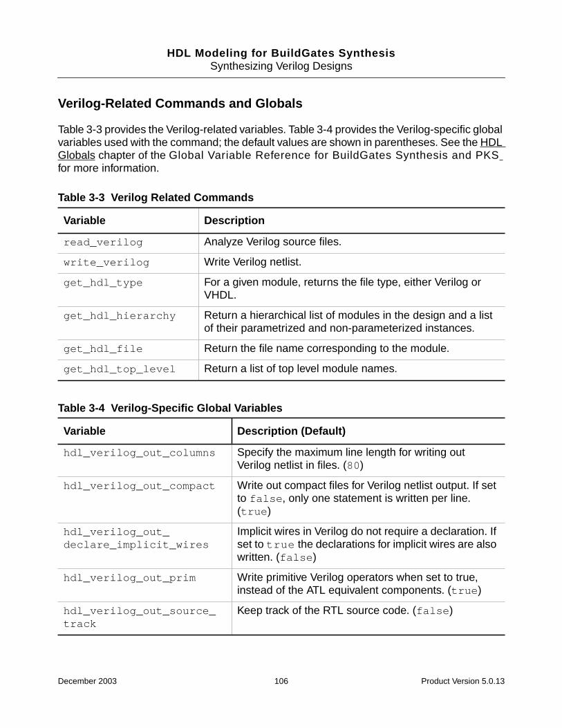
HDL Modeling for BuildGates SynthesisSynthesizing Verilog Designs
Verilog-Related Commands and Globals
Table 3-3 provides the Verilog-related variables. Table 3-4 provides the Verilog-specific globalvariables used with the command; the default values are shown in parentheses. See the HDLGlobals chapter of the Global Variable Reference for BuildGates Synthesis and PKSfor more information.
Table 3-3 Verilog Related Commands
Variable Description
read_verilog Analyze Verilog source files.
write_verilog Write Verilog netlist.
get_hdl_type For a given module, returns the file type, either Verilog orVHDL.
get_hdl_hierarchy Return a hierarchical list of modules in the design and a listof their parametrized and non-parameterized instances.
get_hdl_file Return the file name corresponding to the module.
get_hdl_top_level Return a list of top level module names.
Table 3-4 Verilog-Specific Global Variables
Variable Description (Default)
hdl_verilog_out_columns Specify the maximum line length for writing outVerilog netlist in files. (80)
hdl_verilog_out_compact Write out compact files for Verilog netlist output. If setto false, only one statement is written per line.(true)
hdl_verilog_out_declare_implicit_wires
Implicit wires in Verilog do not require a declaration. Ifset to true the declarations for implicit wires are alsowritten. (false)
hdl_verilog_out_prim Write primitive Verilog operators when set to true,instead of the ATL equivalent components. (true)
hdl_verilog_out_source_track
Keep track of the RTL source code. (false)
December 2003 106 Product Version 5.0.13

HDL Modeling for BuildGates SynthesisSynthesizing Verilog Designs
hdl_verilog_out_unconnected_style
Select the netlisting style for unconnected instancepins. (none)
hdl_verilog_out_use_supply
Specify constant signals (1 or 0) as supply signals(supply1 or supply0). If set to true, the generatedVerilog code will contain supply declarations. If set tofalse, the literal constants 1’b1 and 1’b0 are usedfor connection to power and ground. (false)
hdl_verilog_vpp_arg The variable hdl_verilog_vpp_arg is a stringmade up of the following.Default: ““
-Ipathname - Shows the directories where tosearch for include files.
-Dmacro - Defines the macro equivalent to ‘definemacro.
-Dmacro = value - Defines the macro with thespecified value. Equivalent to the ‘define macrovalue.
naming_style{vhdl | verilog | none}
Determine that the I/O of the object names will takeplace in either VHDL, Verilog or no naming style. Ineffect, it reads and prints object names in thespecified naming style. The difference in the threeoptions is the way in which the escaping of the illegalstring takes place. (Verilog)
hdl_verilog_read_version[1995 | 2001 | dp]
Handle potential incompatibility by enabling Verilogparsing for Verilog–1995, Verilog–2001, and Verilog–DP (datapath).Turns on language-specific errorchecks. (2001)
Table 3-4 Verilog-Specific Global Variables, continued
Variable Description (Default)
December 2003 107 Product Version 5.0.13

HDL Modeling for BuildGates SynthesisSynthesizing Verilog Designs
Supported Verilog Modeling Constructs
■ Verilog, Verilog-2001, and Verilog-DP Constructs and Level of Support on page 108
■ Notes on Verilog Constructs on page 115
Verilog, Verilog-2001, and Verilog-DP Constructs and Level of Support
Table 3-5 lists the level of support for all Verilog HDL constructs and indicates the level as fullysupported (Full), partially supported (Partial), ignored (Ignored), and not supported (No).Wherever possible, restrictions are listed to describe the partially supported languageconstructs. The extension column specifies whether the construct is a Verilog-2001 orVerilog-DP extension, otherwise the construct is Verilog.
For detailed information about the Verilog Datapath Extension (Verilog-DP) constructs, seethe Verilog Datapath Extension Reference.
Table 3-5 Verilog Constructs and Level of Support
Group Construct Support Extension
Basic Identifiers Full
escaped identifiers Full
sized constants (b, o, d, h) Full
unsized constants
2’b11, 3’07, 32’d123, 8’hff
Full
signed constants (s)
3’bs101
Full
string constants No
real constants No
use of z, ? in constants Full
use of x in constants Full
module, endmodule Full
macromodule Full
hierarchical references No
//comment Full
December 2003 108 Product Version 5.0.13
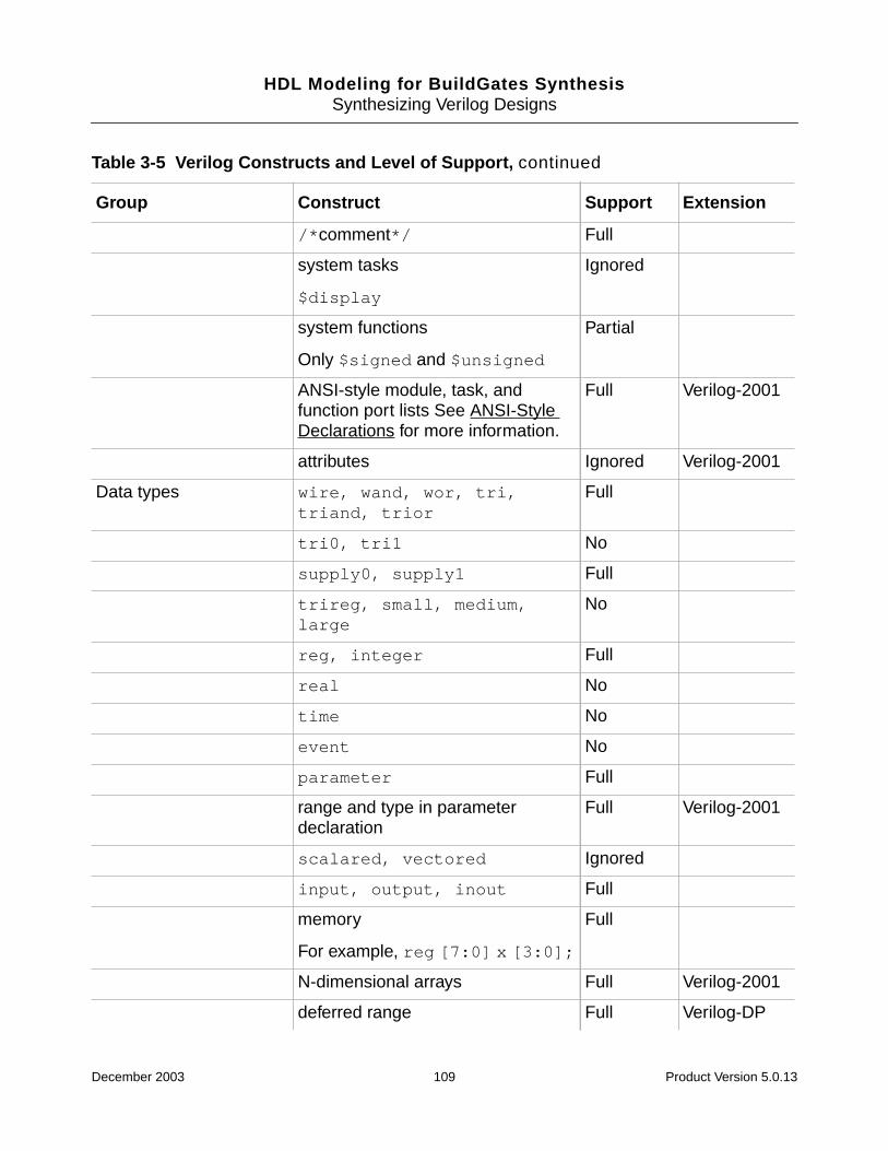
HDL Modeling for BuildGates SynthesisSynthesizing Verilog Designs
/*comment*/ Full
system tasks
$display
Ignored
system functions
Only $signed and $unsigned
Partial
ANSI-style module, task, andfunction port lists See ANSI-StyleDeclarations for more information.
Full Verilog-2001
attributes Ignored Verilog-2001
Data types wire, wand, wor, tri,triand, trior
Full
tri0, tri1 No
supply0, supply1 Full
trireg, small, medium,large
No
reg, integer Full
real No
time No
event No
parameter Full
range and type in parameterdeclaration
Full Verilog-2001
scalared, vectored Ignored
input, output, inout Full
memory
For example, reg [7:0] x [3:0];
Full
N-dimensional arrays Full Verilog-2001
deferred range Full Verilog-DP
Table 3-5 Verilog Constructs and Level of Support, continued
Group Construct Support Extension
December 2003 109 Product Version 5.0.13
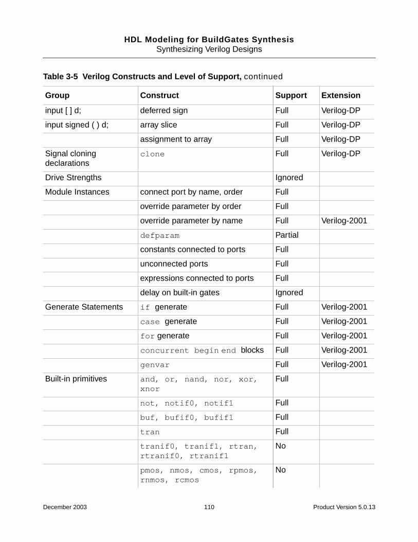
HDL Modeling for BuildGates SynthesisSynthesizing Verilog Designs
input [ ] d; deferred sign Full Verilog-DP
input signed ( ) d; array slice Full Verilog-DP
assignment to array Full Verilog-DP
Signal cloningdeclarations
clone Full Verilog-DP
Drive Strengths Ignored
Module Instances connect port by name, order Full
override parameter by order Full
override parameter by name Full Verilog-2001
defparam Partial
constants connected to ports Full
unconnected ports Full
expressions connected to ports Full
delay on built-in gates Ignored
Generate Statements if generate Full Verilog-2001
case generate Full Verilog-2001
for generate Full Verilog-2001
concurrent begin end blocks Full Verilog-2001
genvar Full Verilog-2001
Built-in primitives and, or, nand, nor, xor,xnor
Full
not, notif0, notif1 Full
buf, bufif0, bufif1 Full
tran Full
tranif0, tranif1, rtran,rtranif0, rtranif1
No
pmos, nmos, cmos, rpmos,rnmos, rcmos
No
Table 3-5 Verilog Constructs and Level of Support, continued
Group Construct Support Extension
December 2003 110 Product Version 5.0.13

HDL Modeling for BuildGates SynthesisSynthesizing Verilog Designs
pullup, pulldown No
User Defined Primitives(UDPs)
primitive No
table No
Datapath Primitives $blend(), $abs(),$sgnmult(), $compge(),$lead0(), $lead1(),$sat(), $round(),$rotatel(), $rotater(),$iroundmult(),$itruncmult()
Full Verilog-DP
Operators andExpressions
+, - (binary and unary) Full
/, %
See Notes on Verilog Constructs onpage 115
Full
* Full
word concatenation Full Verilog-DP
~ Full
Bitwise Operations &, |, ^, ~^, ^~ Full
Reduction Operations &, |, ^, ~&, ~|, ~^, ^~
!, &&, ||
==, !=, <, <=, >, >=
<<, >>
{}, {n{}}
?:
function call
Full
===, !== No
Table 3-5 Verilog Constructs and Level of Support, continued
Group Construct Support Extension
December 2003 111 Product Version 5.0.13

HDL Modeling for BuildGates SynthesisSynthesizing Verilog Designs
Unary Array Operations $reduction_sum(), *, -, +,||, &&, |, &, ^, ~^, ~&,~|, ^~
Full Verilog-DP
Binary Array Operations *, +, -, <<, >>, <<<, >>>,==, !=, >, <, >=, <=, /, %
Full Verilog-DP
Array Transposition $transpose Full Verilog-DP
** Partial Verilog-2001
Event control event or Full
@ Partial
delay and wait (#) Ignored
event or using comma syntax Full Verilog-2001
posedge, negedge Partial
wait Ignored
intra-assignment event control Ignored
event trigger (->) No
Bit and part selects bit-select Full
bit-select of array element Full Verilog-2001
constant part select Full
variable part select ( + : , -:) Full Verilog-2001
variable bit-select on left side of anassignment
Full Verilog-2001
Continuous assignments net and wire declaration Full
using assign Full
use of delay Ignored
Procedural blocks always (exactly one @ required) Partial
initial Ignored
Procedural statements ; Full
Table 3-5 Verilog Constructs and Level of Support, continued
Group Construct Support Extension
December 2003 112 Product Version 5.0.13

HDL Modeling for BuildGates SynthesisSynthesizing Verilog Designs
begin-end Full
if, else Full
repeat*
Note: The repeat statement musthave a constant repeat count.
Full
case, casex, casez, default Full
task enable Full
for (constant bounds, only + and -operation on index)*
Note: Thefor statement must haveconstant bounds.
Partial
while*
Note: The while statement musthave constant bounds.
Partial
forever*
Note: The forever statementmust contain a disable statement.
Partial
*A loop is unrolled to a maximum count specified inhdl_max_loop limit
disable
Note: The disable statementmust be applied to an enclosing taskor named block.
Partial
fork-join No
Procedural assignments blocking (=) assignments Full
non-blocking (<=) assignments Full
procedural continuous assignments(assign)
No
deassign No
force, release No
Table 3-5 Verilog Constructs and Level of Support, continued
Group Construct Support Extension
December 2003 113 Product Version 5.0.13
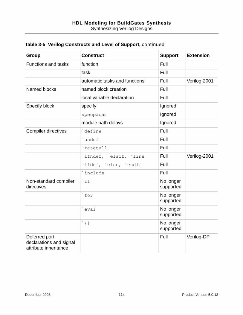
HDL Modeling for BuildGates SynthesisSynthesizing Verilog Designs
Functions and tasks function Full
task Full
automatic tasks and functions Full Verilog-2001
Named blocks named block creation Full
local variable declaration Full
Specify block specify Ignored
specparam Ignored
module path delays Ignored
Compiler directives `define Full
`undef Full
‘resetall Full
`ifndef, `elsif, ‘line Full Verilog-2001
‘ifdef, `else, `endif Full
`include Full
Non-standard compilerdirectives
`if No longersupported
`for No longersupported
`eval No longersupported
`{} No longersupported
Deferred portdeclarations and signalattribute inheritance
Full Verilog-DP
Table 3-5 Verilog Constructs and Level of Support, continued
Group Construct Support Extension
December 2003 114 Product Version 5.0.13
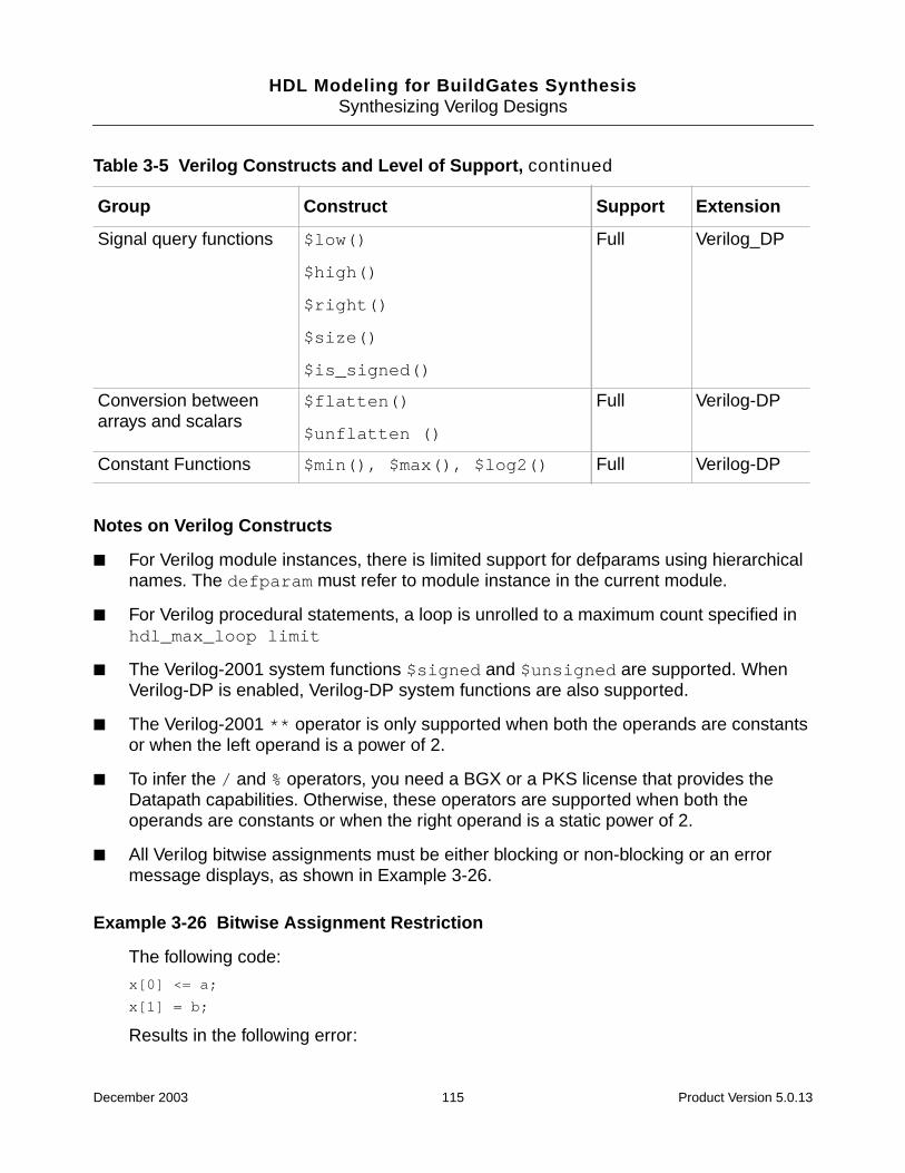
HDL Modeling for BuildGates SynthesisSynthesizing Verilog Designs
Notes on Verilog Constructs
■ For Verilog module instances, there is limited support for defparams using hierarchicalnames. The defparam must refer to module instance in the current module.
■ For Verilog procedural statements, a loop is unrolled to a maximum count specified inhdl_max_loop limit
■ The Verilog-2001 system functions $signed and $unsigned are supported. WhenVerilog-DP is enabled, Verilog-DP system functions are also supported.
■ The Verilog-2001 ** operator is only supported when both the operands are constantsor when the left operand is a power of 2.
■ To infer the / and % operators, you need a BGX or a PKS license that provides theDatapath capabilities. Otherwise, these operators are supported when both theoperands are constants or when the right operand is a static power of 2.
■ All Verilog bitwise assignments must be either blocking or non-blocking or an errormessage displays, as shown in Example 3-26.
Example 3-26 Bitwise Assignment Restriction
The following code:
x[0] <= a;
x[1] = b;
Results in the following error:
Signal query functions $low()
$high()
$right()
$size()
$is_signed()
Full Verilog_DP
Conversion betweenarrays and scalars
$flatten()
$unflatten ()
Full Verilog-DP
Constant Functions $min(), $max(), $log2() Full Verilog-DP
Table 3-5 Verilog Constructs and Level of Support, continued
Group Construct Support Extension
December 2003 115 Product Version 5.0.13

HDL Modeling for BuildGates SynthesisSynthesizing Verilog Designs
==> ERROR: All assignments to individual bits of register ’x’ in module’mixtest’
should be either all blocking or all non-blocking (File /regress/
Verilog/mixed_assign.1.v, Line 9) <CDFG-238>.
■ All Verilog conditional assignments must be either blocking or non-blocking or an errormessage displays as shown in Example 3-27.
Example 3-27 Conditional Assignment Restriction
The following code:
if (s)
x <= a;
else
x = a;
Results in the following error:
==> ERROR: All assignments within a conditional statement should be either
all blocking or all non-blocking (File /regress/
Verilog/mixed_assign.0.v, Line 8) <CDFG-463>.
December 2003 116 Product Version 5.0.13
HDL Modeling for BuildGates SynthesisSynthesizing Verilog Designs
Troubleshooting
Additional troubleshooting information can be found in the latest version of Known Problemsand Solutions for BuildGates Synthesis and Cadence PKS that came with your release.
■ do_build_generic Generates Extremely Long Module Name on page 118
■ Eliminating Busses in a Netlist on page 118
■ Eliminating Unwanted Escape Characters in Front of Signal Names on page 120
■ BuildGates Synthesis Does Not Prune Registers With Their D Inputs Constant onpage 120
■ Preserving Instances from the RTL Through the Optimization Flow on page 121
■ Preserving the set and reset Signals Next to the D-input of the Flip Flops on page 122
■ Preventing Modules from being Overwritten During read_verilog on page 122
■ Using the \ Character in Verilog on page 122
■ Low Power Synthesis Cannot Apply Inferred Enable Register Banks on page 123
■ Honoring ‘defines in an ‘include File in a Verilog Pre-Processor on page 123
■ Removing Bus Objects in the Hierarchy or Module on page 124
■ Generating Incorrect Logic for Asynchronous set and reset Pins on page 125
■ Floating Nets on page 125
December 2003 117 Product Version 5.0.13
HDL Modeling for BuildGates SynthesisSynthesizing Verilog Designs
do_build_generic Generates Extremely Long Module Name
In Verilog modules, parameters are passed that are unique for each module. This informationis added to the module name after using the do_build_generic command even if youhave specified the maximum name length for the module using the set_globaldcn_module_max_length.
This is the expected behavior of the BuildGates Synthesis tool. Use the do_change_namecommand after using the do_build_generic command to replace the long module nameas shown in Example 3-28.
Example 3-28 Changing Module Namesset_global dcn_module_allow_conversion true
set_global dcn_module_max_length
do_change_names -use_rules
Eliminating Busses in a Netlist
➤ To eliminate busses in a netlist use the do_blast_busses command to split the businto single-bit signals.
By default, this command splits the bus nets and bus ports in the whole hierarchy, startingfrom the current module. You have the option to split only bus nets or only bus ports. You cancustomize the generated net names or port names by using the global variable,buscomp_generator.
A bus signal dout[3:0] becomes four separate signals (dout_3, dout_2, dout_1, anddout_0) after you use the following commands:
set_global buscomp_generator {%s_%d} do_blast_busses
If there are conflicts (for example, if you already have a signal called dout_3 before blastingthe bus), BuildGates synthesis will not use the conflicting name, but it will create an arbitraryname. Use a different buscomp_generator to avoid conflicting names.
Resolving Name Mapping Problem with Formal Verification
Removes bus objects in the hierarchy or in the current module. When converted to scalars,use the hdl_array_generator and hdl_record_generator globals to name thescalars for array and record busses and use the buscomp_generator global to name thescalars of all other busses as shown in Example 3-29.
Example 3-29 Resolving Name Mapping Problem with Formal Verification
December 2003 118 Product Version 5.0.13
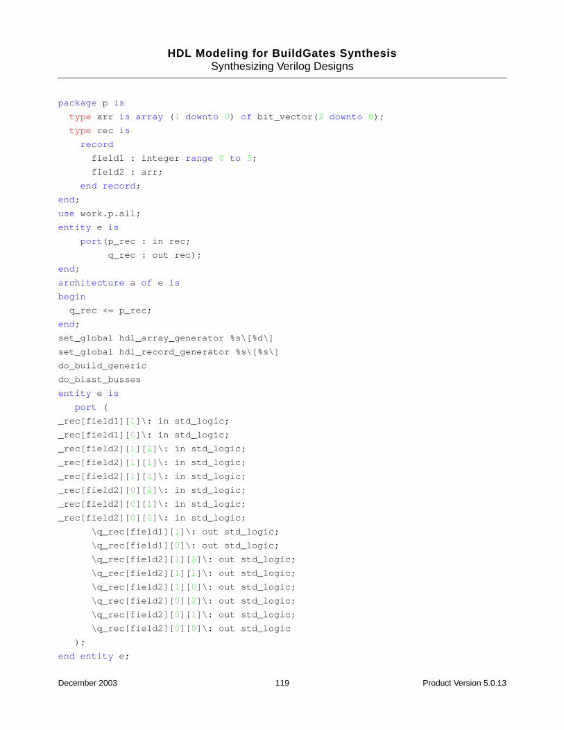
HDL Modeling for BuildGates SynthesisSynthesizing Verilog Designs
package p is
type arr is array (1 downto 0) of bit_vector(2 downto 0);
type rec is
record
field1 : integer range 0 to 3;
field2 : arr;
end record;
end;
use work.p.all;
entity e is
port(p_rec : in rec;
q_rec : out rec);
end;
architecture a of e is
begin
q_rec <= p_rec;
end;
set_global hdl_array_generator %s\[%d\]
set_global hdl_record_generator %s\[%s\]
do_build_generic
do_blast_busses
entity e is
port (
_rec[field1][1]\: in std_logic;
_rec[field1][0]\: in std_logic;
_rec[field2][1][2]\: in std_logic;
_rec[field2][1][1]\: in std_logic;
_rec[field2][1][0]\: in std_logic;
_rec[field2][0][2]\: in std_logic;
_rec[field2][0][1]\: in std_logic;
_rec[field2][0][0]\: in std_logic;
\q_rec[field1][1]\: out std_logic;
\q_rec[field1][0]\: out std_logic;
\q_rec[field2][1][2]\: out std_logic;
\q_rec[field2][1][1]\: out std_logic;
\q_rec[field2][1][0]\: out std_logic;
\q_rec[field2][0][2]\: out std_logic;
\q_rec[field2][0][1]\: out std_logic;
\q_rec[field2][0][0]\: out std_logic
);
end entity e;
December 2003 119 Product Version 5.0.13

HDL Modeling for BuildGates SynthesisSynthesizing Verilog Designs
Eliminating Unwanted Escape Characters in Front of Signal Names
➤ To get rid of the escape characters "\" in front of the signal names, set the followingglobal:
set_global buscomp_generator "%s_%d"
The default setting is %s_%d which means that when a bus is split into individual signals, thesignals will be named SigName[Bit]. This global can be modified to the user’s preference. The%s_%d setting is the most common.
BuildGates Synthesis Does Not Prune Registers With Their D InputsConstant
The optimization engine removes registers whose outputs are tied low, high, or are unused,but keeps registers where the inputs are tied low or high. It is not uncommon for such registersto be used in designs to hold permanent values, such as device ID, company code, or chipversion. For example, you may want a register with the permanent hexadecimal value 1DA5,so when the chip gets placed in a system, the system firmware can read out this value andknows the correct version of the chip.
December 2003 120 Product Version 5.0.13
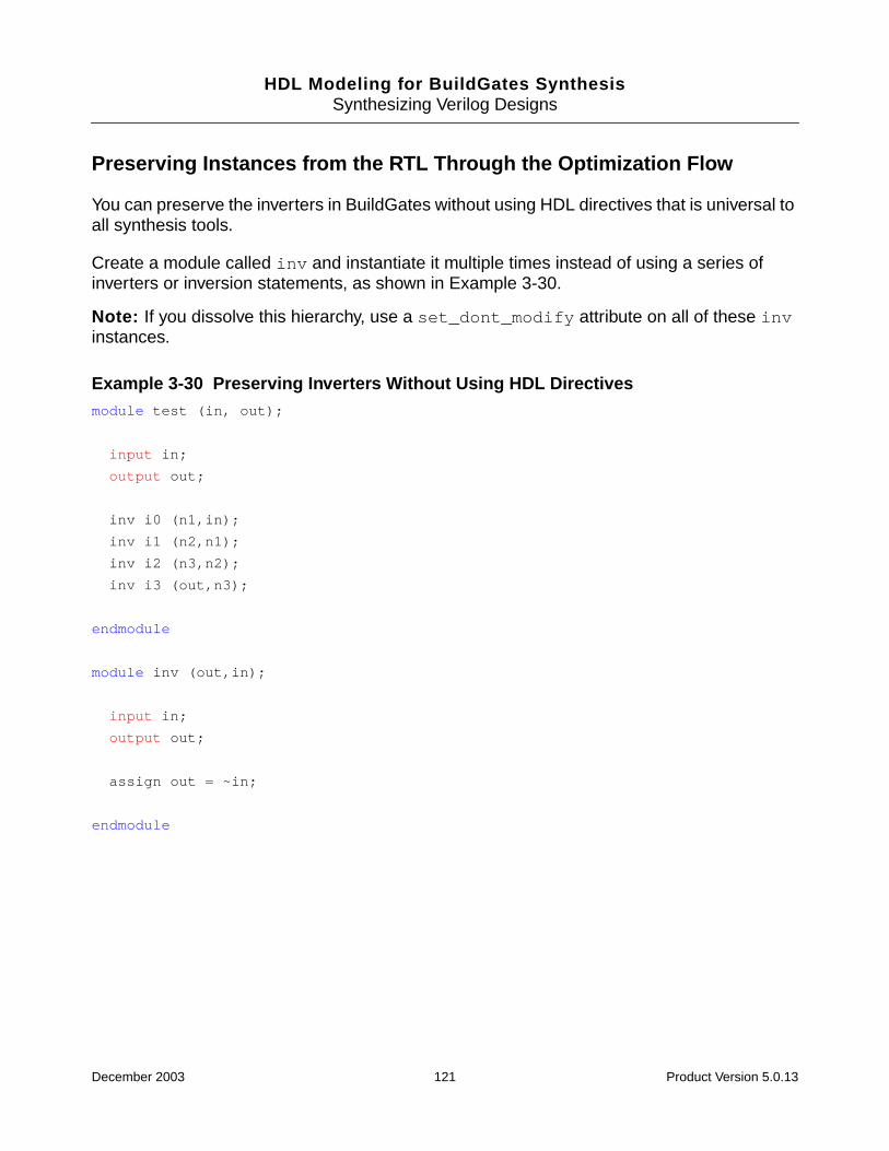
HDL Modeling for BuildGates SynthesisSynthesizing Verilog Designs
Preserving Instances from the RTL Through the Optimization Flow
You can preserve the inverters in BuildGates without using HDL directives that is universal toall synthesis tools.
Create a module called inv and instantiate it multiple times instead of using a series ofinverters or inversion statements, as shown in Example 3-30.
Note: If you dissolve this hierarchy, use a set_dont_modify attribute on all of these invinstances.
Example 3-30 Preserving Inverters Without Using HDL Directivesmodule test (in, out);
input in;
output out;
inv i0 (n1,in);
inv i1 (n2,n1);
inv i2 (n3,n2);
inv i3 (out,n3);
endmodule
module inv (out,in);
input in;
output out;
assign out = ~in;
endmodule
December 2003 121 Product Version 5.0.13
HDL Modeling for BuildGates SynthesisSynthesizing Verilog Designs
Preserving the set and reset Signals Next to the D-input of the Flip Flops
In BuildGates, if you do not have any synchronous set_reset flops in the library, then theset_reset signals will be placed in a gate close to the D-input of the flop. However, if thereis a critical signal fanning in to the D-input, then the set_reset signal is not guaranteed tobe close to the D-input.
BuildGates Synthesis does not preserve the logic close to the D input. However, there aredirectives that you can specify in the RTL that guide the tool to optimally implement theset_reset signals.
➤ Use the following directive for synchronous set to reset signals:
// ambit synthesis set_reset synchronous signals = signal_name_list
Refer to Signal Directives on page 101 for more information.
Preventing Modules from being Overwritten During read_verilog
The read_verilog command will overwrite modules of the same name with the last oneread in. To solve this problem, use Ambit Databases (adb’s) by using the write_adbcommand when writing out each independently optimized block instead ofwrite_verilog. When you read these adb’s of the sub-blocks into the top level usingread_adb, BuildGates Synthesis will rename modules of the same name automatically;appending a _0, _1, and so on to the end of the original module name (unless you specifythe -overwrite switch).
Using the \ Character in Verilog
Use the \ character in Verilog to specify characters which are not legal in Verilog. So if youwant to include characters in a name which are illegal in Verilog, add a \ before the name,and add a space after the name.
December 2003 122 Product Version 5.0.13
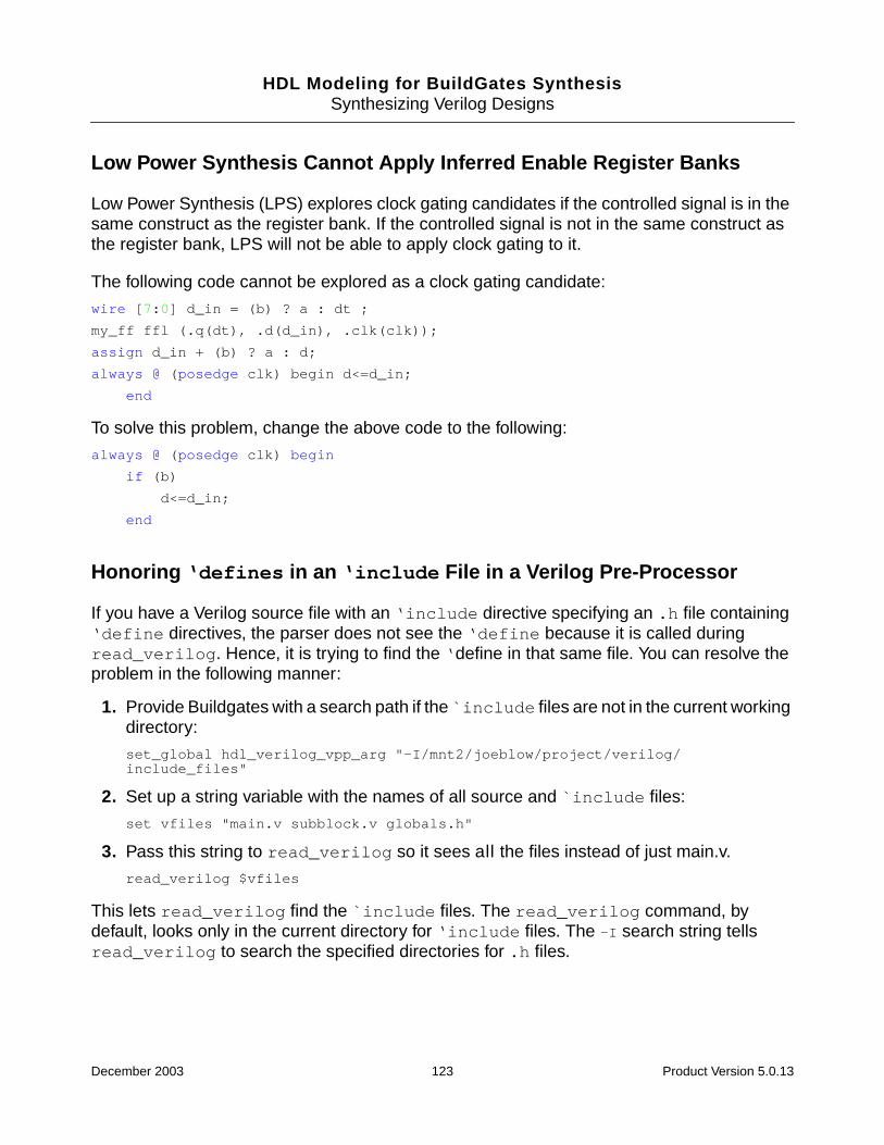
HDL Modeling for BuildGates SynthesisSynthesizing Verilog Designs
Low Power Synthesis Cannot Apply Inferred Enable Register Banks
Low Power Synthesis (LPS) explores clock gating candidates if the controlled signal is in thesame construct as the register bank. If the controlled signal is not in the same construct asthe register bank, LPS will not be able to apply clock gating to it.
The following code cannot be explored as a clock gating candidate:
wire [7:0] d_in = (b) ? a : dt ;
my_ff ffl (.q(dt), .d(d_in), .clk(clk));
assign d_in + (b) ? a : d;
always @ (posedge clk) begin d<=d_in;
end
To solve this problem, change the above code to the following:
always @ (posedge clk) begin
if (b)
d<=d_in;
end
Honoring ‘defines in an ‘include File in a Verilog Pre-Processor
If you have a Verilog source file with an ‘include directive specifying an .h file containing‘define directives, the parser does not see the ‘define because it is called duringread_verilog. Hence, it is trying to find the ‘define in that same file. You can resolve theproblem in the following manner:
1. Provide Buildgates with a search path if the `include files are not in the current workingdirectory:
set_global hdl_verilog_vpp_arg "-I/mnt2/joeblow/project/verilog/include_files"
2. Set up a string variable with the names of all source and `include files:
set vfiles "main.v subblock.v globals.h"
3. Pass this string to read_verilog so it sees all the files instead of just main.v.
read_verilog $vfiles
This lets read_verilog find the `include files. The read_verilog command, bydefault, looks only in the current directory for ‘include files. The -I search string tellsread_verilog to search the specified directories for .h files.
December 2003 123 Product Version 5.0.13
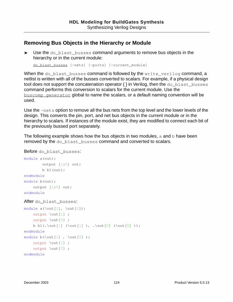
HDL Modeling for BuildGates SynthesisSynthesizing Verilog Designs
Removing Bus Objects in the Hierarchy or Module
➤ Use the do_blast_busses command arguments to remove bus objects in thehierarchy or in the current module:
do_blast_busses [-nets] [-ports] [-current_module]
When the do_blast_busses command is followed by the write_verilog command, anetlist is written with all of the busses converted to scalars. For example, if a physical designtool does not support the concatenation operator { } in Verilog, then the do_blast_bussescommand performs this conversion to scalars for the current module. Use thebuscomp_generator global to name the scalars, or a default naming convention will beused.
Use the -nets option to remove all the bus nets from the top level and the lower levels of thedesign. This converts the pin, port, and net bus objects in the current module or in thehierarchy to scalars. If instances of the module exist, they are modified to connect each bit ofthe previously bussed port separately.
The following example shows how the bus objects in two modules, a and b have beenremoved by the do_blast_busses command and converted to scalars.
Before do_blast_busses:
module a(out);
output [1:0] out;
b b1(out);
endmodule
module b(out);
output [1:0] out;
endmodule
After do_blast_busses:
module a(\out[1], \out[0]);
output \out[1] ;
output \out[0] ;
b b1(.\out[1] (\out[1] ), .\out[0] (\out[0] ));
endmodule
module b(\out[1] , \out[0] );
output \out[1] ;
output \out[0] ;
endmodule
December 2003 124 Product Version 5.0.13

HDL Modeling for BuildGates SynthesisSynthesizing Verilog Designs
Generating Incorrect Logic for Asynchronous set and reset Pins
Incorrect logic for a flip-flop with asynchronous set and reset pins is generated when thereis an if-then-else statement that controls the assignment to the flip-flop nested withinthe if-then-else branch, as shown in Example 3-31.
Example 3-31 Using Incorrect set and reset Logicalways @ (posedge clk or posedge set or posedge reset)
if (set)
out <= 1’bl;
else if (reset)
if (en)
out <= 1’bl;
else
out <= in;
A workaround is to rewrite the RTL to remove the nested if-then-else statement asshown in Example 3-32.
Example 3-32 Using Correct set and reset Logicalways @ (posedge clk or posedge set or posedge reset)
if (set)
out <= l’bl;
else if (reset)
out <= !en;
else
out <= in;
Floating Nets
By default, BuildGates Synthesis ties floating inputs to ground.
➤ To create a floating pin, attach it to a net that is not driven and set the following global tonone:
set_global hdl_undrivin_net_value none
This keeps the net attached to the pin, but leaves it floating. You must read the netlistafter setting this global.
December 2003 125 Product Version 5.0.13
HDL Modeling for BuildGates SynthesisSynthesizing Verilog Designs
December 2003 126 Product Version 5.0.13

HDL Modeling for BuildGates Synthesis
4Verilog-2001 Extensions
This chapter describes how to handle incompatibilities between the Verilog versions andexplains the new Verilog-2001 synthesis-specific features relevant to RTL synthesis. Thefeatures supported in this release include a reference to the corresponding chapter numberof the Verilog-2001 LRM.
■ Overview on page 128
■ Verilog-2001 Hardware Description Language Extensions on page 128
December 2003 127 Product Version 5.0.13

HDL Modeling for BuildGates SynthesisVerilog-2001 Extensions
Overview
Verilog-2001 is the latest version of the IEEE 1364 Verilog HDL standard. The Verilog-2001extensions are a superset of the existing Verilog-1995 language. These extensions increasedesign productivity and enhance synthesis capability. Prior knowledge and experience ofVerilog-1995 is assumed. The new Verilog-2001 language features supported in this releaseare explained in detail in the IEEE 1364-2001 Verilog HDL standard LanguageReference Manual (LRM).
Verilog-2001 Hardware Description Language Extensions
The following Verilog-2001 HDL extensions are supported in this release and are explainedin the following sections:
■ Verilog-1995, Verilog-2001, and Verilog Datapath Modes of Parsing on page 129
■ Generate Statements on page 129 (LRM 12.1.3)
■ Multidimensional Arrays on page 134 (LRM 3.10)
■ Automatic Functions and Tasks on page 135 (LRM 10)
■ Parameter Passing by Name on page 135 (LRM 12.2.2.2)
■ Comma-Separated Sensitivity List on page 136
■ ANSI-Style Declarations on page 136 (LRM 12.3.4)
■ Variable Part Selects on page 137 (LRM 4.2.1)
■ Constant Functions on page 137 (LRM 10.3.5)
■ New Preprocessor Directives on page 138 (LRM 19)
The following Verilog-2001 extensions are not supported in this release:
■ Automatic Width Extension Beyond 32 Bits (LRM 2.5.1)
■ Reg Declaration Initial Assignment (LRM 6.2.1)
■ Attributes (LRM 2.8)
December 2003 128 Product Version 5.0.13
HDL Modeling for BuildGates SynthesisVerilog-2001 Extensions
Verilog-1995, Verilog-2001, and Verilog Datapath Modes of Parsing
➤ To handle potential incompatibilities, BuildGates supports separate Verilog-2001,Verilog-1995, or Verilog-DP (datapath) modes of parsing using the following globalvariable:
set_global hdl_verilog_read_version [ 1995 | 2001 | dp ]
In addition to enabling Verilog parsing for Verilog-1995, Verilog-2001, or Verilog-DP, the globalvariable hdl_verilog_read_version also turns on language-specific error checks. Forexample, in Verilog-2001 it is illegal to assign values to a whole array, but this is legal inVerilog-DP.
In most cases, a Verilog-2001 design behaves like a Verilog-1995 design. Verilog-2001 addsseveral new keywords to the Verilog language. Older models, which happen to use one ofthese new reserved words, will not work with a Verilog-2001 simulator or other software tools.For example, generate is a new keyword in Verilog-2001, therefore, a Verilog-1995 designthat has a wire name generate will not compile under Verilog-2001 rules.
Verilog-DP (datapath) is an upwardly compatible, proprietary extension to Verilog-2001 thatincludes a concise datapath description language to facilitate complex, highly parameterizeddatapath designs. See Datapath for BuildGates Synthesis and Cadence PKS for moreinformation on Verilog-DP extensions.
Generate Statements
Use Verilog generate statements to conditionally compile concurrent constructs. TheVerilog-2001 generate statements are modeled on VHDL generate statements.
Concurrent Begin and End Blocks
The begin/end keywords are used to group concurrent statements within a generatestatement. A begin/end block must be labeled if declarations are included within it. Thereare three types of generate statements:
■ if generate Statement – Performs a set of concurrent statements if a specifiedcondition is met.
■ case generate Statement – Behaves like a nested if statement. Selects from a set ofconcurrent statements.
■ for generate Statement – Replicates a set of concurrent statements.
December 2003 129 Product Version 5.0.13
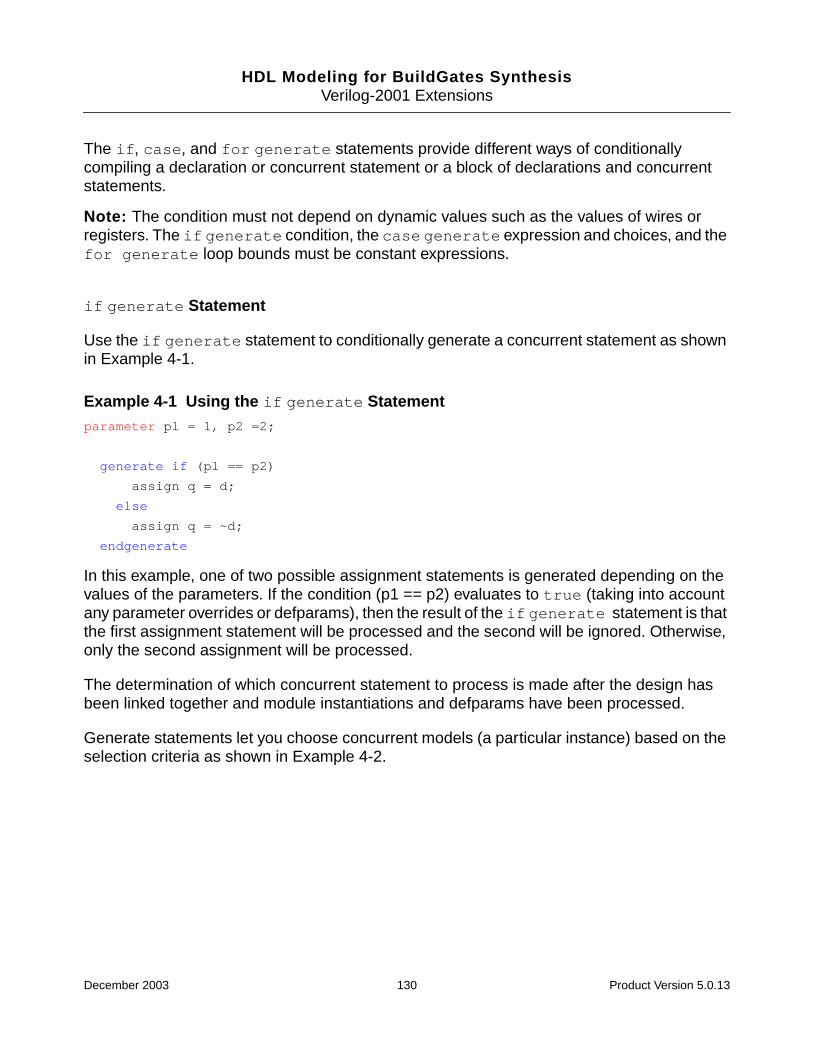
HDL Modeling for BuildGates SynthesisVerilog-2001 Extensions
The if, case, and for generate statements provide different ways of conditionallycompiling a declaration or concurrent statement or a block of declarations and concurrentstatements.
Note: The condition must not depend on dynamic values such as the values of wires orregisters. The if generate condition, the case generate expression and choices, and thefor generate loop bounds must be constant expressions.
if generate Statement
Use the if generate statement to conditionally generate a concurrent statement as shownin Example 4-1.
Example 4-1 Using the if generate Statementparameter pl = 1, p2 =2;
generate if (pl == p2)
assign q = d;
else
assign q = ~d;
endgenerate
In this example, one of two possible assignment statements is generated depending on thevalues of the parameters. If the condition (p1 == p2) evaluates to true (taking into accountany parameter overrides or defparams), then the result of the if generate statement is thatthe first assignment statement will be processed and the second will be ignored. Otherwise,only the second assignment will be processed.
The determination of which concurrent statement to process is made after the design hasbeen linked together and module instantiations and defparams have been processed.
Generate statements let you choose concurrent models (a particular instance) based on theselection criteria as shown in Example 4-2.
December 2003 130 Product Version 5.0.13
HDL Modeling for BuildGates SynthesisVerilog-2001 Extensions
Example 4-2 Using the if generate Statementmodule crc_gen (a,b,crc_out);
parameter a_width = 8,b_width = 15;
parameter crc_en =1, crc8 =1;
input [a_width-1:0] a;
input [b_width-1:0] b;
input crc_en, crc8;
output crc_out;
generate
if ((crc_en == 1’b1) & (crc8 == 1’b1))
CRC8 #(a_width) U1 (a, crc_en, crc_out); // Instantiate an 8 bit crc generator
else
CRC16 #(b_width) U1 (b, crc_en, crc_out); // Instantiate a 16 bit crcgenerator
endgenerate // The generated instance is U1
endmodule
case generate Statement
Use a case generate statement for multi-way branching in a functional description asshown in Example 4-3.
Example 4-3 Using the case generate Statement for Multi-Way Branchingparameter p = 2;
generate case (p)
1: assign q = d
2: assign q = ~d;
3: assign q = 1’bl;
default: assign q = 1’bl;
endcase
endgenerate
The value of p determines which one of the assignment statements is processed. The caseexpression (p) is evaluated after the design has been linked together.
December 2003 131 Product Version 5.0.13
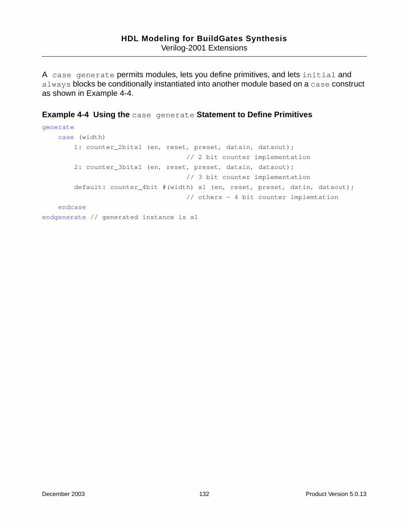
HDL Modeling for BuildGates SynthesisVerilog-2001 Extensions
A case generate permits modules, lets you define primitives, and lets initial andalways blocks be conditionally instantiated into another module based on a case constructas shown in Example 4-4.
Example 4-4 Using the case generate Statement to Define Primitivesgenerate
case (width)
1: counter_2bitx1 (en, reset, preset, datain, dataout);
// 2 bit counter implementation
2: counter_3bitx1 (en, reset, preset, datain, dataout);
// 3 bit counter implementation
default: counter_4bit #(width) x1 (en, reset, preset, datin, dataout);
// others - 4 bit counter implemtation
endcase
endgenerate // generated instance is x1
December 2003 132 Product Version 5.0.13
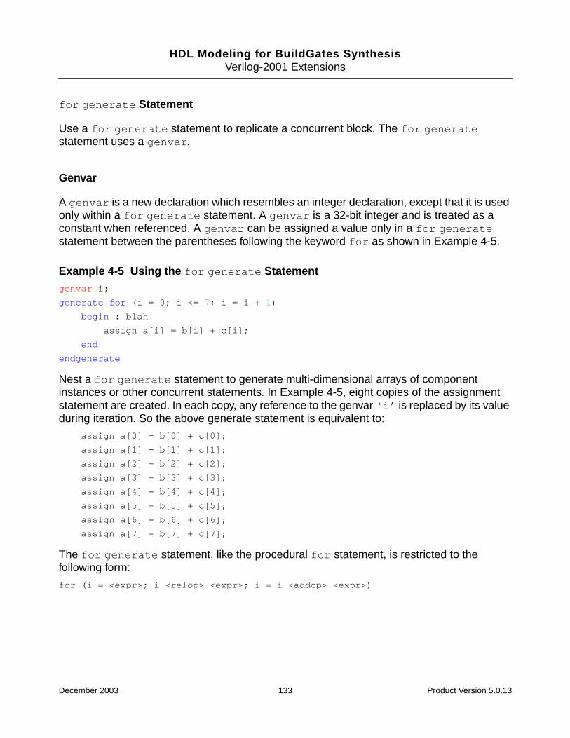
HDL Modeling for BuildGates SynthesisVerilog-2001 Extensions
for generate Statement
Use a for generate statement to replicate a concurrent block. The for generatestatement uses a genvar.
Genvar
A genvar is a new declaration which resembles an integer declaration, except that it is usedonly within a for generate statement. A genvar is a 32-bit integer and is treated as aconstant when referenced. A genvar can be assigned a value only in a for generatestatement between the parentheses following the keyword for as shown in Example 4-5.
Example 4-5 Using the for generate Statementgenvar i;
generate for (i = 0; i <= 7; i = i + 1)
begin : blah
assign a[i] = b[i] + c[i];
end
endgenerate
Nest a for generate statement to generate multi-dimensional arrays of componentinstances or other concurrent statements. In Example 4-5, eight copies of the assignmentstatement are created. In each copy, any reference to the genvar ‘i’ is replaced by its valueduring iteration. So the above generate statement is equivalent to:
assign a[0] = b[0] + c[0];
assign a[1] = b[1] + c[1];
assign a[2] = b[2] + c[2];
assign a[3] = b[3] + c[3];
assign a[4] = b[4] + c[4];
assign a[5] = b[5] + c[5];
assign a[6] = b[6] + c[6];
assign a[7] = b[7] + c[7];
The for generate statement, like the procedural for statement, is restricted to thefollowing form:
for (i = <expr>; i <relop> <expr>; i = i <addop> <expr>)
December 2003 133 Product Version 5.0.13
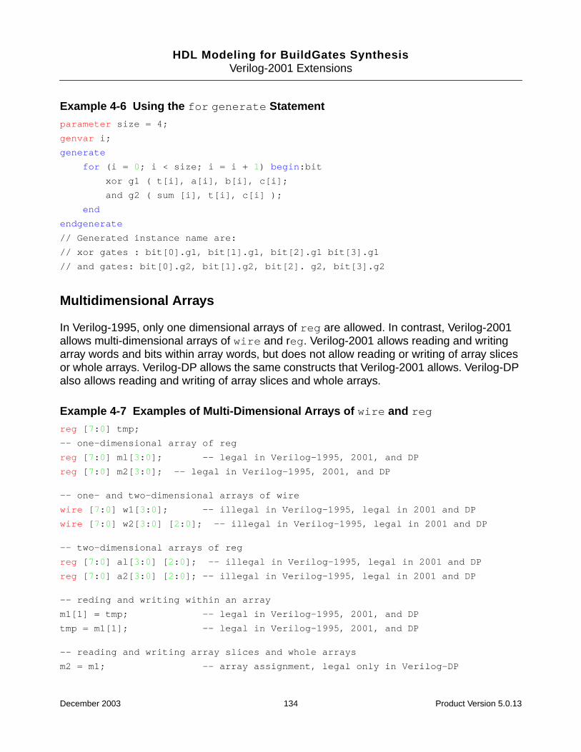
HDL Modeling for BuildGates SynthesisVerilog-2001 Extensions
Example 4-6 Using the for generate Statementparameter size = 4;
genvar i;
generate
for (i = 0; i < size; i = i + 1) begin:bit
xor g1 ( t[i], a[i], b[i], c[i];
and g2 ( sum [i], t[i], c[i] );
end
endgenerate
// Generated instance name are:
// xor gates : bit[0].g1, bit[1].g1, bit[2].g1 bit[3].g1
// and gates: bit[0].g2, bit[1].g2, bit[2]. g2, bit[3].g2
Multidimensional Arrays
In Verilog-1995, only one dimensional arrays of reg are allowed. In contrast, Verilog-2001allows multi-dimensional arrays of wire and reg. Verilog-2001 allows reading and writingarray words and bits within array words, but does not allow reading or writing of array slicesor whole arrays. Verilog-DP allows the same constructs that Verilog-2001 allows. Verilog-DPalso allows reading and writing of array slices and whole arrays.
Example 4-7 Examples of Multi-Dimensional Arrays of wire and reg
reg [7:0] tmp;
-- one-dimensional array of reg
reg [7:0] ml[3:0]; -- legal in Verilog-1995, 2001, and DP
reg [7:0] m2[3:0]; -- legal in Verilog-1995, 2001, and DP
-- one- and two-dimensional arrays of wire
wire [7:0] w1[3:0]; -- illegal in Verilog-1995, legal in 2001 and DP
wire [7:0] w2[3:0] [2:0]; -- illegal in Verilog-1995, legal in 2001 and DP
-- two-dimensional arrays of reg
reg [7:0] al[3:0] [2:0]; -- illegal in Verilog-1995, legal in 2001 and DP
reg [7:0] a2[3:0] [2:0]; -- illegal in Verilog-1995, legal in 2001 and DP
-- reding and writing within an array
m1[1] = tmp; -- legal in Verilog-1995, 2001, and DP
tmp = m1[1]; -- legal in Verilog-1995, 2001, and DP
-- reading and writing array slices and whole arrays
m2 = m1; -- array assignment, legal only in Verilog-DP
December 2003 134 Product Version 5.0.13
HDL Modeling for BuildGates SynthesisVerilog-2001 Extensions
m2[3:2] = m1[1:0]; -- array slice, legal only in Verilog-DP
Automatic Functions and Tasks
Verilog-1995 functions or tasks use static memory for arguments and local variables, whichis why a task enable is not permitted in a concurrent context. If two tasks start at the sametime, they will write over each other’s data.
Verilog-2001 includes reentrant procedures that are implemented so more than one processcan perform it at the same time without conflict. By using the keyword automatic to mark atask or function that performs in a per-call context (just as C or VHDL functions or proceduresdo), Verilog compilers treat the variables inside of the task as unique stacked variables. Theparameters and local variables for these procedures are allocated immediately when they arecalled and then discarded when the procedures exit.
The BuildGates software treats Verilog functions and tasks as automatic procedures, whetherthe keyword automatic is specified or not. For this reason, synthesis of a non-automaticfunction or task, which relies on static allocation of local variables, will produce a simulationmismatch.
Parameter Passing by Name
Verilog-1995 defines two ways to change parameters for instantiated modules: parameterredefinition and defparam statements.
Verilog-2001 lets you specify module instance parameters (like module instance ports) byname, as shown in the following example.
Example 4-8 Specifying Module Instance Parameters by Namemod #(.width(1), .length(2)) ul(q,d);
Passing parameters by name is similar to defparam statements, except only the parametersthat change are referenced in named port instantiations.
Example 4-9 Using the defparam Keyworddefparam ul.width = 1;
defparam u1.length = 2;
mod ul (q,d);
December 2003 135 Product Version 5.0.13

HDL Modeling for BuildGates SynthesisVerilog-2001 Extensions
Comma-Separated Sensitivity List
Verilog-1995 uses the keyword or as a separator between signals in the sensitivity list.Verilog-2001 lets a comma take the place of the keyword or in an event list as shown inExample 4-10.
Example 4-10 Using a Comma-Separated Sensitivity Listalways @ (posedge clk, negedge reset)
ANSI-Style Declarations
The Verilog-1995 mode uses the older Kernighan and Ritchie C language syntax to declaremodule ports, as shown in Example 4-11, which requires that module header ports bedeclared up to three times: in the module header port list, in an output port declaration, andin a reg data-type declaration. Verilog-2001 updates the syntax for declaring ports andparameters in a more ANSI C fashion, as shown in Example 4-11, which combines theheader port list, port direction, and data-type declarations into a single declaration, as shownbelow:
Example 4-11 Verilog-1995 Style Declarationmodule m(q, d);
parameter p = 1;
output q;
reg q;
input d;
wire d;
always @d
assign q = d;
endmodule
Example 4-12 Verilog-2001 ANSI C-like Declarationmodule m #(parameter p + 1)
(output reg q, input wire d);
always @d
assign q = d;
endmodule
Use this enhancement in functions and tasks to make port declarations more compact.
December 2003 136 Product Version 5.0.13

HDL Modeling for BuildGates SynthesisVerilog-2001 Extensions
Variable Part Selects
Verilog-1995 permits variable bit selects of a vector, but the part selects must be constant;thus, you cannot use a variable to select a specific byte out of a word.
Verilog-2001 lets a slice have a variable base offset and a constant width. This means thatthe starting point of the part select can vary during simulation run time, but the width of thepart select remains constant, as shown in Example 4-13.
Example 4-13 Variable Part Selectwire [31:0] d;
wire [3:0] x;
wire [3:0] q;
asssign q = d[x+:4];
is equivalent to the following:
assign q = {d[x+3], d[x+2], d[x+1], d[x]};
Constant Functions
A constant expression is required in certain contexts, for example, when specifying a rangein a declaration or a part select. In Verilog-1995, a constant expression can be a literal, aparameter, or some arithmetic expression whose operands are constant expressions.Verilog-2001 allows a function call to appear in a constant expression in certaincircumstances. Mainly, the arguments to the function must be constant expressions, and thefunction must compute its result entirely on the basis of its arguments.
In Example 4-14, the functions min and max are used to size the declaration of wire x.Because these functions are called with constant arguments, and return a result based onlyon their arguments, their calls are considered constant expressions. In Verilog-1995, it isillegal to use a function call in sizing a declaration.
December 2003 137 Product Version 5.0.13
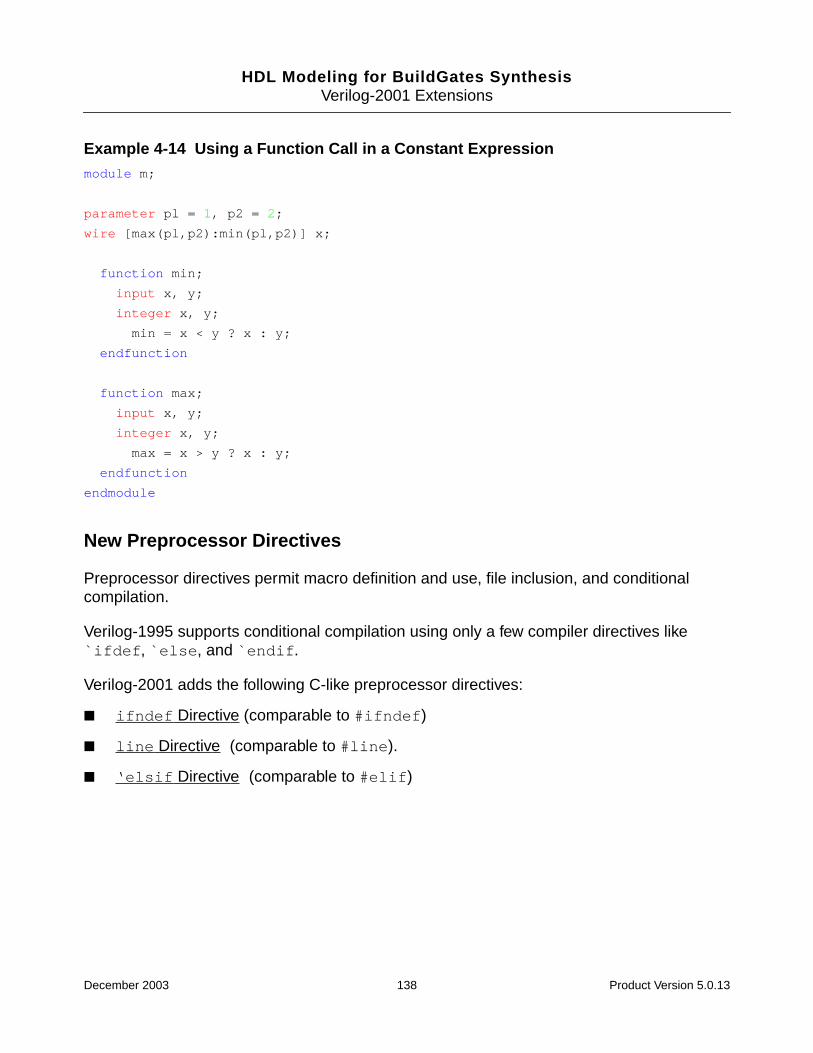
HDL Modeling for BuildGates SynthesisVerilog-2001 Extensions
Example 4-14 Using a Function Call in a Constant Expressionmodule m;
parameter pl = 1, p2 = 2;
wire [max(pl,p2):min(pl,p2)] x;
function min;
input x, y;
integer x, y;
min = x < y ? x : y;
endfunction
function max;
input x, y;
integer x, y;
max = x > y ? x : y;
endfunction
endmodule
New Preprocessor Directives
Preprocessor directives permit macro definition and use, file inclusion, and conditionalcompilation.
Verilog-1995 supports conditional compilation using only a few compiler directives like`ifdef, `else, and `endif.
Verilog-2001 adds the following C-like preprocessor directives:
■ ifndef Directive (comparable to #ifndef)
■ line Directive (comparable to #line).
■ ‘elsif Directive (comparable to #elif)
December 2003 138 Product Version 5.0.13
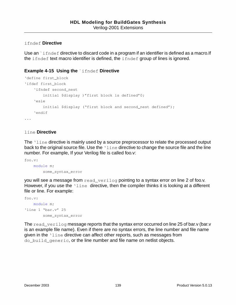
HDL Modeling for BuildGates SynthesisVerilog-2001 Extensions
ifndef Directive
Use an `ifndef directive to discard code in a program if an identifier is defined as a macro.Ifthe ifndef text macro identifier is defined, the ifndef group of lines is ignored.
Example 4-15 Using the `ifndef Directive‘define first_block
‘ifdef first_block
‘ifndef second_nest
initial $display )”first block is defined”0;
‘esle
initial $display (“first block and second_nest defined”);
‘endif
...
line Directive
The ‘line directive is mainly used by a source preprocessor to relate the processed outputback to the original source file. Use the ‘line directive to change the source file and the linenumber. For example, If your Verilog file is called foo.v:
foo.v:
module m;
some_syntax_error
you will see a message from read_verilog pointing to a syntax error on line 2 of foo.v.However, if you use the ‘line directive, then the compiler thinks it is looking at a differentfile or line. For example:
foo.v:
module m;
‘line 1 “bar.v” 25
some_syntax_error
The read_verilogmessage reports that the syntax error occurred on line 25 of bar.v (bar.vis an example file name). Even if there are no syntax errors, the line number and file namegiven in the ‘line directive can affect other reports, such as messages fromdo_build_generic, or the line number and file name on netlist objects.
December 2003 139 Product Version 5.0.13
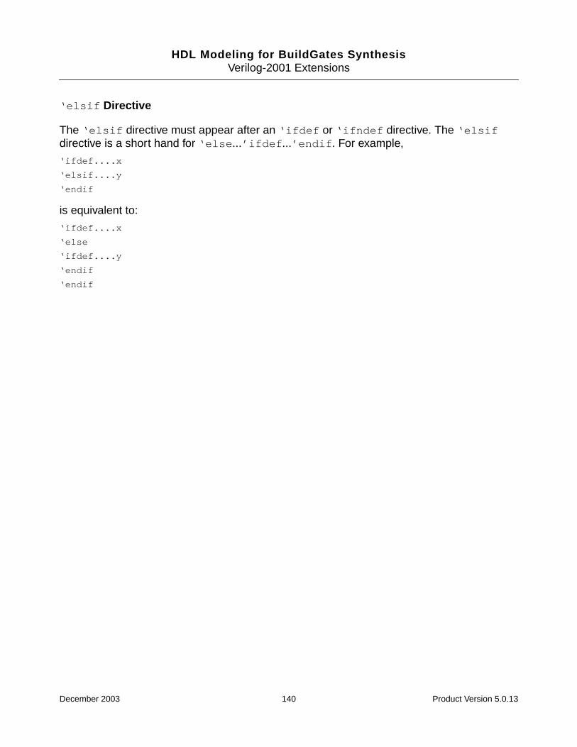
HDL Modeling for BuildGates SynthesisVerilog-2001 Extensions
‘elsif Directive
The ‘elsif directive must appear after an ‘ifdef or ‘ifndef directive. The ‘elsifdirective is a short hand for ‘else...’ifdef...’endif. For example,
‘ifdef....x
‘elsif....y
‘endif
is equivalent to:
‘ifdef....x
‘else
‘ifdef....y
‘endif
‘endif
December 2003 140 Product Version 5.0.13
HDL Modeling for BuildGates Synthesis
5Synthesizing VHDL Designs
This chapter explains how to synthesize VHDL designs using VHDL synthesis commands,VHDL synthesis directives, and VHDL modeling styles in the following sections.
■ Overview on page 142
■ Tasks on page 143
■ Additional Information on page 159
■ Troubleshooting on page 210
December 2003 141 Product Version 5.0.13

HDL Modeling for BuildGates SynthesisSynthesizing VHDL Designs
Overview
Use BuildGates Synthesis to synthesize VHDL designs. See Tasks on page 143 for detailedinformation. See VHDL-Related Commands and Globals on page 196 for a list of commandsand globals used to synthesize VHDL designs.
Use VHDL to construct a gate level netlist from a register-transfer level VHDL model. Twomodels may simulate identically and describe the same behavior (functionality) of a design.However, the implementation of the two models through logic synthesis can differ significantlyin terms of their gate count (area), critical paths, and physical characteristics. The section,VHDL Modeling Styles on page 163 describes the impact that different VHDL modeling styleshave on logic synthesis and netlist generation.
The BuildGates Synthesis tool supports both the VHDL’87 and VHDL’93 modeling styleswhich adhere to the ANSI/IEEE standards on VHDL language definition. See VHDLConstructs on page 199 for a list of supported VHDL modeling constructs.
The synthesizable subset of VHDL is based on the IEEE P1076.6 Standard for VHDLRegister Transfer Level Synthesis. For more detail on the VHDL syntax and semantics,refer to the following IEEE Standard VHDL Language Reference Manuals:
■ ANSI/IEEE Std 1076-1987 (for VHDL’87)
■ ANSI/IEEE Std 1076-1993 (for VHDL’93)
Use synthesis directives to control the synthesis process. See VHDL Synthesis Directives onpage 174 for more information.
Perform RTL synthesis, as shown in Figure 5-1 after loading the timing and power libraries.For information on reading libraries, see Using Timing Libraries in the Timing Analysisfor BuildGates Synthesis and Cadence Physically Knowledgeable Synthesis (PKS).
For detailed RTL flow information, see RTL Synthesis Flow in Chapter 1.
December 2003 142 Product Version 5.0.13
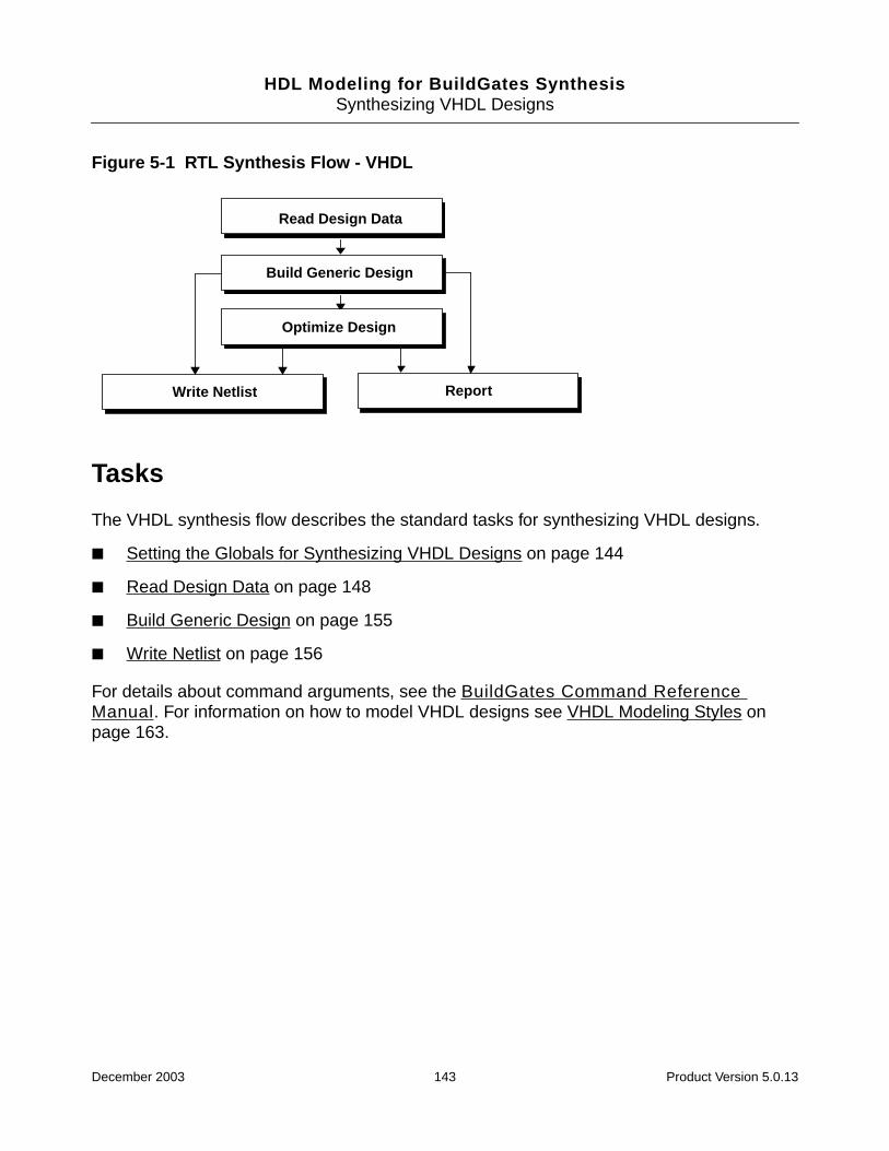
HDL Modeling for BuildGates SynthesisSynthesizing VHDL Designs
Figure 5-1 RTL Synthesis Flow - VHDL
Tasks
The VHDL synthesis flow describes the standard tasks for synthesizing VHDL designs.
■ Setting the Globals for Synthesizing VHDL Designs on page 144
■ Read Design Data on page 148
■ Build Generic Design on page 155
■ Write Netlist on page 156
For details about command arguments, see the BuildGates Command ReferenceManual. For information on how to model VHDL designs see VHDL Modeling Styles onpage 163.
Read Design Data
ReportWrite Netlist
Build Generic Design
Optimize Design
December 2003 143 Product Version 5.0.13
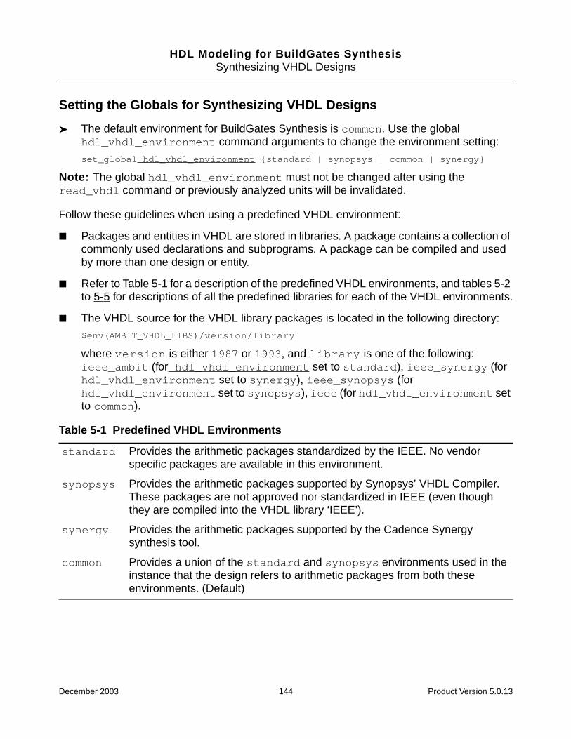
HDL Modeling for BuildGates SynthesisSynthesizing VHDL Designs
Setting the Globals for Synthesizing VHDL Designs
➤ The default environment for BuildGates Synthesis is common. Use the globalhdl_vhdl_environment command arguments to change the environment setting:
set_global hdl_vhdl_environment {standard | synopsys | common | synergy}
Note: The global hdl_vhdl_environment must not be changed after using theread_vhdl command or previously analyzed units will be invalidated.
Follow these guidelines when using a predefined VHDL environment:
■ Packages and entities in VHDL are stored in libraries. A package contains a collection ofcommonly used declarations and subprograms. A package can be compiled and usedby more than one design or entity.
■ Refer to Table 5-1 for a description of the predefined VHDL environments, and tables 5-2to 5-5 for descriptions of all the predefined libraries for each of the VHDL environments.
■ The VHDL source for the VHDL library packages is located in the following directory:
$env(AMBIT_VHDL_LIBS)/version/library
where version is either 1987 or 1993, and library is one of the following:ieee_ambit (for hdl_vhdl_environment set to standard), ieee_synergy (forhdl_vhdl_environment set to synergy), ieee_synopsys (forhdl_vhdl_environment set to synopsys), ieee (for hdl_vhdl_environment setto common).
Table 5-1 Predefined VHDL Environments
standard Provides the arithmetic packages standardized by the IEEE. No vendorspecific packages are available in this environment.
synopsys Provides the arithmetic packages supported by Synopsys’ VHDL Compiler.These packages are not approved nor standardized in IEEE (even thoughthey are compiled into the VHDL library ‘IEEE’).
synergy Provides the arithmetic packages supported by the Cadence Synergysynthesis tool.
common Provides a union of the standard and synopsys environments used in theinstance that the design refers to arithmetic packages from both theseenvironments. (Default)
December 2003 144 Product Version 5.0.13

HDL Modeling for BuildGates SynthesisSynthesizing VHDL Designs
.
Table 5-2 Predefined VHDL Libraries Standard Environment
Library Package(s)
AMBIT attributes
STD standard
textio
IEEE std_logic_1164
numeric_bit
numeric_std
Table 5-3 Predefined VHDL Libraries Synopsys Environment
Library Package(s)
AMBIT attributes
STD standard
textio
SYNOPSYS attributes
bv_arithmetic
IEEE std_logic_1164
std_logic_arith
std_logic_misc
std_logic_signed
std_logic_textio
std_logic_unsigned
Table 5-4 Predefined VHDL Libraries Synergy Environment
Library Packages
AMBIT attributes
December 2003 145 Product Version 5.0.13

HDL Modeling for BuildGates SynthesisSynthesizing VHDL Designs
STD standard
textio
SYNERGY constraints
signed_arith
std_logic_misc
IEEE std_logic_1164
std_logic_arith
std_logic_textio
Table 5-5 Predefined VHDL Libraries Common Environment
Library Packages
AMBIT attributes
STD standard
textio
SYNOPSYS attributes
bv_arithmetic
IEEE numeric_bit
numeric_std
std_logic_1164
std_logic_arith
std_logic_misc
std_logic_signed
std_logic_textio
std_logic_unsigned
vital_primitives
vital_timing
Table 5-4 Predefined VHDL Libraries Synergy Environment, continued
December 2003 146 Product Version 5.0.13

HDL Modeling for BuildGates SynthesisSynthesizing VHDL Designs
Verifying VHDL Code Compliance with the LRM
➤ Set the following global variable to true to enforce a strict interpretation of the VHDLLanguage Reference Manual (LRM) in order to guarantee portability to other VHDLtools:
set_global hdl_vhdl_lrm_compliance {true | false}
Default: false.
December 2003 147 Product Version 5.0.13

HDL Modeling for BuildGates SynthesisSynthesizing VHDL Designs
Read Design Data
Defining Logical Libraries
➤ Use the set_vhdl_library command arguments to define a new logical library:
set_vhdl_library library_name directory_name
VHDL designs are stored in libraries. A library is a storage area in the host environment forcompiled entities, architectures, packages, and configurations and is useful for managingmultiple design projects.
Follow these guidelines to define a logical library:
■ Each logical library used in a design, except the library WORK, must be associated witha physical directory, using the set_vhdl_library command.
■ The directory name must be a valid path to an existing directory. This preserves thecontents of the library from one synthesis run to another. For example:
set_vhdl_library MYLIB /home/me/vhdlibs/lib1
Use the read_vhdl command after the set_vhdl_library command to analyze thefile design.vhd into library MYLIB.
read_vhdl -library MYLIB design.vhd
Mapping the WORK Library to an Existing Logical Library
➤ Use the set_vhdl_library command arguments to map the WORK library to anexisting logical library:
set_vhdl_library WORK library
Many different design libraries may exist simultaneously. Only one of them can be used asthe actual working library. The name of this logical library is WORK. By default, the library WORKis mapped to the logical library TEMP. An error message is generated if two VHDL libraries aremapped to the same physical directory.
Follow these guidelines to map the WORK library to a logical library:
■ The library name must be the name of an existing logical library.
■ All subsequent read_vhdl commands must have an explicit -library flag, or the fileswill be analyzed and stored into the last library to which WORK was mapped. For example:
set_vhdl_library MYLIB /home/me/vhdlibs/lib1
December 2003 148 Product Version 5.0.13
HDL Modeling for BuildGates SynthesisSynthesizing VHDL Designs
Analyzing and Storing a VHDL File into a Library
➤ Use the read_vhdl command arguments to analyze and store information into a library:
read_vhdl [-aware_library aware_libname] | [-library libname]vhdl_filenames
Follow these guidelines to analyze and store a VHDL file into a library:
■ The following commands are identical. They analyze and store design.vhd intolibrary MYLIB:
set_vhdl_library WORK MYLIB
read_vhdl -library MYLIB design.vhd
■ An error message is generated if an attempt is made to analyze a VHDL design unit intoone of the standard libraries (STD, AMBIT, IEEE, SYNERGY, SYNOPSYS) without mappingthe library to a new directory using the set_vhdl_library command.
Showing the Mapping between VHDL Logical Libraries and the CorrespondingDirectory
➤ Use the report_vhdl_library command arguments to show the mapping betweenVHDL logical libraries and the directory:
report_vhdl_library [-verbose] [library] [{ > | >> } filename]
Using Arithmetic Packages From Other Vendors
1. Use the global hdl_vhdl_environment arguments to set up your VHDL environment:
set_global hdl_vhdl_environment { standard | synopsys| common | synergy}
2. Use the set_vhdl_library command arguments to redefine the library IEEE to a newdirectory:
set_vhdl_library library_name directory_name
For example:
set_vhdl_library IEEE dir_name
3. Use the read_vhdl command arguments to analyze vendor-specific packages:
read_vhdl [-aware_library aware_libname] | [-library libname]vhdl_filenames
VHDL does not predefine arithmetic operators on types that hold bits. Using arithmeticpackages lets you synthesize VHDL designs that include arithmetic operators.
Follow these guidelines when using arithmetic packages from other vendors:
December 2003 149 Product Version 5.0.13
HDL Modeling for BuildGates SynthesisSynthesizing VHDL Designs
Important
Using the hdl_vhdl_environment global is especially important because thearithmetic packages associated with the standard, synergy, common, andsynopsys environments are tagged with special directives that let the toolimplement them efficiently.
■ If some of the VHDL designs have references to arithmetic packages from othersynthesis vendors they must be compiled into a library named IEEE.
■ Analyze a predefined VHDL package before reading in other vendor-specific packagesthat are required in the IEEE library. Read any VHDL entities that use these packages.
■ There is no order restriction in reading entities and packages. However, if an entity refersto a package, read in the package before the entity.
■ Because the local copy of the IEEE library was created using the set_vhdl_librarycommand, the corresponding directory is preserved after exiting from shell. Whenreentering the shell environment, reuse the IEEE library created above by redefiningthe IEEE library.
Example:
read_vhdl -library IEEE package
Resetting a VHDL Library
➤ Use the reset_vhdl_library command argument to remove all VHDL units thathave been analyzed into a specific library.
reset_vhdl_library library_name
Reset a VHDL library if you mistakenly analyzed a package into the wrong library, or if youwant to clear the library of all analyzed VHDL units and start over.
Make sure the library_name argument is the name of the library where you want to deleteall analyzed units.
The following example resets library MYLIB after a VHDL package from wrongpack.vhdwas analyzed into it:
read_vhdl -library MYLIB wrongpack.vhd
reset_vhdl_library MYLIB
Read the correct package into MYLIB:
read_vhdl -library MYLIB rightpack.vhd
December 2003 150 Product Version 5.0.13

HDL Modeling for BuildGates SynthesisSynthesizing VHDL Designs
Switching between VHDL’87 and VHDL’93
➤ Use the global hdl_vhdl_read_version to specify the VHDL version used to readVHDL designs:
set_global hdl_vhdl_read_version { 1987 | 1993 }
Default: 1993
Use this global to ensure that only VHDL files that conform to the VHDL’87 standard or theVHDL’93 standard are parsed successfully.
Note: When the value of the global hdl_vhdl_read_version is changed, the tool resetsthe libraries STD, IEEE, and AMBIT to the default values for the language setting. Therefore,you need to redefine the library IEEE to use other vendor-specific IEEE packages analyzedinto the correct VHDL version. See Using Arithmetic Packages From Other Vendors onpage 149 for more information on incorporating vendor-specific IEEE packages into thelibrary IEEE.
Follow these guidelines when switching between VHDL read versions:
■ BuildGates Synthesis supports both 1987 and 1993 versions of VHDL.You can read inVHDL designs that are modeled using different versions. You can also read in VHDLdesigns in one version and write out the synthesized netlist in another version.
■ For all the packages that are part of the predefined VHDL environment, both the VHDL’87and VHDL’93 versions are precompiled and shipped with the tool.
■ If your project requires a mix of VHDL versions to be read in, use the same version ofVHDL for reading both sets of VHDL files.
■ If it is essential that the different sets of files be read in with the appropriate version-specific syntax checking, then read in the VHDL code for the 1987 version and elaborateit with do_build_generic and save out the generic ADB file. Repeat these steps forthe code using the 1993 version. In a new bg_shell session, read in the generic ADBfiles, run do_build_generic to link the designs together, then proceed withconstraining and optimizing the design.
Reusing Previously Analyzed Entities
➤ Use the global hdl_vhdl_reuse_units to import VHDL entities that were previouslyanalyzed into a library:
set_global hdl_vhdl_reuse_units { true | false }
For large designs, analyze all the VHDL files into a library once and then reuse the analyzedentities in subsequent synthesis sessions.
December 2003 151 Product Version 5.0.13
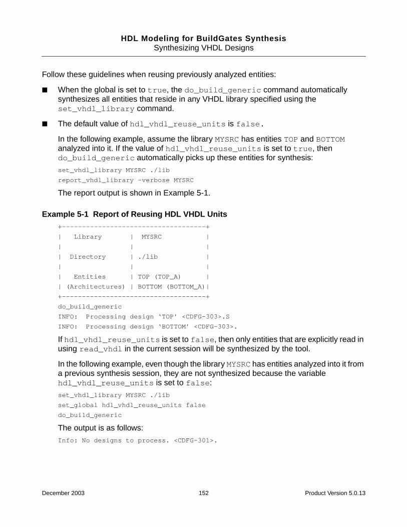
HDL Modeling for BuildGates SynthesisSynthesizing VHDL Designs
Follow these guidelines when reusing previously analyzed entities:
■ When the global is set to true, the do_build_generic command automaticallysynthesizes all entities that reside in any VHDL library specified using theset_vhdl_library command.
■ The default value of hdl_vhdl_reuse_units is false.
In the following example, assume the library MYSRC has entities TOP and BOTTOManalyzed into it. If the value of hdl_vhdl_reuse_units is set to true, thendo_build_generic automatically picks up these entities for synthesis:
set_vhdl_library MYSRC ./lib
report_vhdl_library -verbose MYSRC
The report output is shown in Example 5-1.
Example 5-1 Report of Reusing HDL VHDL Units+------------------------------------+
| Library | MYSRC |
| | |
| Directory | ./lib |
| | |
| Entities | TOP (TOP_A) |
| (Architectures) | BOTTOM (BOTTOM_A)|
+------------------------------------+
do_build_generic
INFO: Processing design ‘TOP’ <CDFG-303>.S
INFO: Processing design ‘BOTTOM’ <CDFG-303>.
If hdl_vhdl_reuse_units is set to false, then only entities that are explicitly read inusing read_vhdl in the current session will be synthesized by the tool.
In the following example, even though the library MYSRC has entities analyzed into it froma previous synthesis session, they are not synthesized because the variablehdl_vhdl_reuse_units is set to false:
set_vhdl_library MYSRC ./lib
set_global hdl_vhdl_reuse_units false
do_build_generic
The output is as follows:
Info: No designs to process. <CDFG-301>.
December 2003 152 Product Version 5.0.13
HDL Modeling for BuildGates SynthesisSynthesizing VHDL Designs
Specifying the Naming Style of Object Names
➤ Use the global naming_style to specify whether the input and output of object nameswill be in VHDL or no naming style:
set_global naming_style {vhdl | verilog | none}
Modifying the Case of VHDL Names
➤ Use the global hdl_vhdl_case variables to specify the case of VHDL names stored inthe tool:
set_global hdl_vhdl_case { lower | upper | original }
Example
set_global hdl_vhdl_case lower
The case of VHDL names is only relevant for references to foreign modules. Examples offoreign references are Verilog modules and library cells.
Follow these guidelines when modifying the case of VHDL names:
■ lower—converts all names to lower-case (Xpg is stored as xpg).
■ upper—converts all names to upper-case (Xpg is stored as XPG).
■ original—preserves the case used in the declaration of the object (Xpg is stored asXpg).
■ If the global hdl_vhdl_case is set to original, use the same case you used whendefining the object when referring to foreign objects. Thus, VHDL components and portnames should be identical in case to the Verilog module definition.
Getting HDL File Names, Hierarchy, and Top Level Design Names
The get_hdl commands can be used right after reading the HDL files into BuildGatesSynthesis without having to first generate a generic netlist. Refer to Querying the HDL DesignPool on page 33 for information on how to use these commands.
■ Using the get_hdl_top_level Command on page 35
■ Using the get_hdl_hierarchy Command on page 35
■ Using the get_hdl_type Command on page 36
■ Using the get_hdl_file Command on page 36
December 2003 153 Product Version 5.0.13

HDL Modeling for BuildGates SynthesisSynthesizing VHDL Designs
Selecting Preferred Architectures
➤ Use the global hdl_vhdl_preferred_architecture to specify the name of thearchitecture you prefer to use with an entity when multiple architectures are available:
set_global hdl_vhdl_preferred_architecture name
Before synthesis can proceed, every referenced entity in a VHDL design description must bebound with a corresponding architecture. The architecture describes the actual function orcontents of the entity to which it is bound.
Follow these guidelines when selecting an architecture:
■ For arithmetic components, base architectural decisions on the type of cells available inthe target technology library.
■ When an entity has multiple architectures, the tool selects the architecture that will beused to synthesize the entity by evaluating the following rules in the order listed.
❑ The global variable hdl_vhdl_preferred_architecture overrides any VHDLentity architecture binding rules. For example:
set_global hdl_vhdl_preferred_architecture synth
If the entity, foo, has two architectures named sim and synth, the tool binds footo entity synth. By default, hdl_vhdl_preferred_architecture is set to thenull string ("").
❑ If the entity is being synthesized as an instantiation in a higher level entity, then anyexplicit architecture binding specified for that instantiation is used to determine thearchitecture implementation of the current entity. Configuration specifications andcomponent configurations (instances I2 and I8 respectively in ComponentInstantiations and Bindings on page 160) can be used explicitly to specify the entity-architecture to which the instance is bound.
❑ If the entity has a corresponding configuration declaration, the entity is bound to thearchitecture specified in the top-level block of the configuration declaration. Forexample, the configuration BOTTOM_CONF in the example on Restrictions on Entitieswith Multiple Architectures on page 162 binds entity BOTTOM to architecture A1.
❑ If none of the previous rules apply, the tool binds the entity to the most recentlyanalyzed architecture (also known as the default architecture). For example:Assume entity MRA has two architectures: A1 and A2. A1 is analyzed first followedby A2. The synthesis of entity MRA will use architecture A2.
Note: Once an entity has been synthesized, the only way to resynthesize it with adifferent architecture (perhaps by modifying a configuration declaration) is to reanalyzethe entity and its architectures. For the same reason, the globalhdl_vhdl_preferred_architecture should only be set prior to any
December 2003 154 Product Version 5.0.13
HDL Modeling for BuildGates SynthesisSynthesizing VHDL Designs
do_build_generic command.
Build Generic Design
➤ Use the do_build_generic command options to transform the VHDL design into ahierarchical, gate-level netlist consisting of technology-independent logic gates:
do_build_generic [-all] [-module name] [-extract_fsm] [-group_all_processes][-group_named_processes] [-group_process list_of_processes][-group_all_subprograms] [-group_subprograms list_of_subprograms][-parameters | -generics tcl_list] [-sleep_mode]
Follow these guidelines when building a generic design:
■ Use the do_build_generic command after specifying the source VHDL files for theinitial design database and before using the do_optimize command. The generatednetlist can then be written as a VHDL netlist (write_vhdl).
■ Run do_build_generic on a netlist even if it is already mapped to the target library.After using the command, any instance of a target library cell in the source descriptionremains mapped to that cell in the design database. Load the netlist later for optimizationand analysis using the read_vhdl and read_adb commands, respectively.
■ By default, the do_build_generic command treats all procedural blocks (processes)as part of the module in which they appear without any hierarchy. Use the -group optionto customize and control logical partitions grouped by various processes.
■ Use the do_build_generic command options to generate netlists for selectedmodules in the design hierarchy. See Component Instantiations and Bindings onpage 160 for more information.
■ See Synthesizing a Specified Module on page 36 to build specific modules, multiple top-level designs, and parameterized designs.
December 2003 155 Product Version 5.0.13
HDL Modeling for BuildGates SynthesisSynthesizing VHDL Designs
Write Netlist
Writing Architectures
➤ Set the global hdl_vhdl_write_architecture to true to write VHDL entities:
set_global hdl_vhdl_write_architecture {true | false}
Architectures are used to implement a design entity. There may be more than onearchitecture for a design entity.
Defining Architecture Names
➤ Use the global hdl_vhdl_write_architecture_name to specify the name of thearchitecture for each entity in the netlist:
set_global hdl_vhdl_write_architecture_name architecture_name
The default architecture name is netlist.
You can also add an optional ‘%s’ to the architecture name, which is replaced by theentity name. Use the following to automatically assign different names to the variousarchitectures in your design:
set_global hdl_vhdl_write_architecture_name architecture_name_%s
For example, if a design has two modules, TOP and BOTTOM, the following command,results in two differently named architectures: netlist_TOP and netlist_BOTTOM:
set_global hdl_vhdl_write_architecture_name "netlist_%s"
The following command, however, results in a VHDL netlist where both modules havearchitectures with the name, netlist:
set_global hdl_vhdl_write_architecture_name "netlist"
Note: Giving the global hdl_vhdl_write_architecture_name a value with anyformat specification having more than one ’%s’ results in an error. For example,netlist, %s, A_%s_B are all acceptable; A%s%s is not.
Writing out Modules in Top-Down or Bottom-Up Order
➤ Use the following global variables to control whether VHDL netlists write out modules intop-down or bottom-up order:
set_global hdl_write_top_down {true | false}
Default: false
December 2003 156 Product Version 5.0.13
HDL Modeling for BuildGates SynthesisSynthesizing VHDL Designs
Writing VHDL Entities
The top of every design hierarchy must be an entity.
➤ Set the global hdl_vhdl_write_entity to true to write VHDL entities whenwrite_vhdl is called:
set_global hdl_vhdl_write_entity {true | false}
Specifying the VHDL Entity Name
➤ Use the global hdl_vhdl_write_entity_name to specify the name for the entityrepresenting the current module during VHDL netlisting:
set_global hdl_vhdl_write_entity_name string
A complete VHDL description needs to contain at least one entity.
Follow these guidelines when specifying the VHDL entity name:
■ This variable only affects the name of the current top-level module in hierarchicaldesigns; all descendant modules use their own names.
■ If you set the variable to the empty string (““), the current module name is used as theentity name. The default value is ““.
Selecting the Bit-Level Type
➤ Use the global hdl_vhdl_write_bit_type to define the bit-level type used in VHDLnetlists:
set_global hdl_vhdl_write_bit_type { std_logic | std_ulogic }
Default: std_logic.
For example, the following command maps bit ports to internal std_ulogic ports andinteger ports to internal std_ulogic_vector signals:
set_global hdl_vhdl_write_bit_type std_ulogic
Note: If you do not want to preserve the original VHDL port types, use the -no_wrapoption to write the module with std_logic types. Refer to the write_vhdl commandin the Command Reference for BuildGates Synthesis and Cadence PKS fordetails.
December 2003 157 Product Version 5.0.13
HDL Modeling for BuildGates SynthesisSynthesizing VHDL Designs
Follow these guidelines when selecting the bit type in which VHDL netlists will be written:
■ When saving the VHDL file with the write_vhdl command, the netlister preserves theport types of the current entity’s ports during netlisting. This requires generation ofconversion functions that transform potentially complex VHDL port types to a simpler bit-level representation. Such conversion functions are encapsulated in a package that isgenerated by the netlister.
■ All descendant module ports are always written with the equivalent bit-levelrepresentation.
■ For a module that did not originate as a VHDL entity, the module’s ports are also writtenout with the equivalent bit-level representation.
Selecting Between VHDL’87 and VHDL’93
➤ Use the global hdl_vhdl_write_version variables to specify the VHDL version ofthe netlists that are written out using the write_vhdl command.
set_global hdl_vhdl_write_version { 1987 | 1993 }
Default: 1993
Follow these guidelines when selecting between VHDL’87 and VHDL’93:
■ The global ensures that the VHDL netlists that are written out conform to the VHDL’87standard. For example:
set_global hdl_vhdl_write_version 1987
■ If you write VHDL netlists in the VHDL’87 mode, avoid illegal names that might begenerated by synthesis. When busses are bit-blasted, the individual net names areformatted as specified by the global buscomp_generator. By default, names for thenets of a bus are generated with the square brackets (b[1]). Such names are illegal inVHDL ‘87 and are avoided by setting the following global prior to anydo_build_generic command. To avoid escaped values, set the buscomp generator:
set_global buscomp_generator %s_%d
This does not apply to VHDL ‘93 mode netlists, because a name such as b[1] is writtenout as an escaped name \b[1]\.
Referring to VHDL Packages in Netlists
➤ Use the global hdl_vhdl_write_packages to specify the set of library and useclauses that must precede every module written out:
set_global hdl_vhdl_write packages lib1.pack_x...
December 2003 158 Product Version 5.0.13
HDL Modeling for BuildGates SynthesisSynthesizing VHDL Designs
For example, entering the following command:
set_global hdl_vhdl_write_packages "ieee.std_logic_1164 atl.comps1 atl.comps2"
Results in the following clauses preceding every module written out:
library ieee;
use ieee.std_logic_1164.all;
library atl;
use atl.comps1.all;
use atl.comps2.all;
The default value of this global is “ieee.std_logic_1164”.
Writing Component Declarations
➤ Use the global hdl_vhdl_write_components to specify whether the netlister shouldwrite out component declarations for the technology cells that are referred to within themodules:
set_global hdl_vhdl_write_components {true | false }
If the component declarations for all the cells in the technology library clib areencapsulated in a package called components, writing component declarations forindividual modules is disabled by setting hdl_vhdl_write_components to false,and making the components package visible to all modules being written out. Forexample:
set_global hdl_vhdl_write_components false
Writing a VHDL Netlist
➤ Use the write_vhdl command arguments to write out a VHDL netlist:
write_vhdl [-hierarchical] [-equation] [-no_wrap] vhdl_file_name
Additional Information
■ Hierarchical VHDL Designs on page 160
■ VHDL Modeling Styles on page 163
■ VHDL Synthesis Directives on page 174
■ Supported Synopsys Directives on page 191
■ VHDL-Related Commands and Globals on page 196
■ VHDL Constructs on page 199
December 2003 159 Product Version 5.0.13
HDL Modeling for BuildGates SynthesisSynthesizing VHDL Designs
Hierarchical VHDL Designs
■ Component Instantiations and Bindings on page 160
■ Restrictions on Entities with Multiple Architectures on page 162
Component Instantiations and Bindings
BuildGates Synthesis supports several types of component instantiations in hierarchicalVHDL designs.
Consider an entity BOTTOM that has two architectures: A1 and A2. Example 5-2 illustrates thevarious ways in which entity BOTTOM can be instantiated for synthesis and bound to a specificentity architecture pair for implementation:
Instances I1, I2, I3, and I4 are examples of component instantiations that refer tocomponent declarations. Instance I1 of component BOTTOM relies on a default binding toentity BOTTOM. The default architecture (the most recently analyzed) A2 is selected forimplementing I1. The configuration specification for I2 binds the component COMP to entityBOTTOM, default architecture A2. The configuration specification for instance I3 binds COMPexplicitly to entity BOTTOM and its architecture A1. The configuration specification for I4references the configuration BOTTOM_CONF, which binds I4 to entity BOTTOM andarchitecture A2.
Instances I5 and I6 are examples of entity instantiations where the entity being instantiatedis directly referred to in the instantiation. Since no architecture is specified in instantiation I5,the default architecture A2 is used for implementing this component instance. Instance I6instantiates entity BOTTOM and implements with architecture A1.
Instance I7 is an instantiation that uses a configuration to indicate the entity and architecturethat is used to implement the instance.
Instances I8 and I9 illustrate that the binding for component instances are specified ascomponent configurations in a configuration declaration. Instance I8 of COMP is bound toentity BOTTOM and architecture A1, while instance I9 is bound to the entity BOTTOM andarchitecture A2 specified in configuration BOTTOM_CONF.
Use block configurations in configuration declarations to configure architectures. Componentconfigurations must not have any generic maps or port maps. In other words, even thoughthe component declaration COMP may be bound to entity BOTTOM, the generics and ports ofthe component declaration must match that of the entity it is bound to.
December 2003 160 Product Version 5.0.13

HDL Modeling for BuildGates SynthesisSynthesizing VHDL Designs
Example 5-2 Instantiating an Entity for Synthesisentity BOTTOM is .....
architecture A1 of BOTTOM is .....
architecture A2 of BOTTOM is .....
configuration BOTTOM_CONF of BOTTOM is .....
for A2
end for;
end configuration BOTTOM_CONF;
entity TOP is .....
architecture A of TOP is
component BOTTOM .....
component COMP .....
for I2 : COMP use entity work.BOTTOM;
for I3 : COMP use entity work.BOTTOM (A1);
for I4 : COMP use configuration work.BOTTOM_CONF;
begin
-- instantiate component BOTTOM, default architecture
I1 : BOTTOM .....
-- instantiate component COMP bound to entity BOTTOM
I2 : COMP .....
I3 : COMP .....
I4 : COMP .....
- instantiate entity BOTTOM, default architecture
I5 : entity work.BOTTOM .....
-- instantiate entity BOTTOM, architecture A1
I6 : entity work.BOTTOM(A1) .....
-- instantiate entity/architecture in BOTTOM_CONF
I7 : configuration work.BOTTOM_CONF .....
-- instantiate component,binding in configuration
-- declaration
I8 : COMP .....
I9 : COMP .....
end architecture A;
configuration TOP_CONF of TOP is
for A
for I8 : COMP use entity work.BOTTOM(A1);
for I9 : COMP use configuration work.BOTTOM_CONF;
end for;
end configuration TOP_CONF
December 2003 161 Product Version 5.0.13
HDL Modeling for BuildGates SynthesisSynthesizing VHDL Designs
Restrictions on Entities with Multiple Architectures
In VHDL, an entity can have multiple architectures (one for synthesis and one for simulation).Although you can analyze an entity that has multiple architectures, the tool restricts an entityto be bound to exactly one architecture in a single session of synthesis. In other words, oncean entity is bound to a specific architecture, it must be bound to that same architectureeverywhere in the design.
The design shown in Example 5-3, is not synthesizable because instances I1 and I2 bindcomponent COMP to different architectures of entity BOTTOM:
Example 5-3 Non-Synthesizable Designentity TOP is .....
architecture A of TOP is
component COMP is .....
for I1 : COMP use entity work.BOTTOM (A1);
for I2 : COMP use entity work.BOTTOM (A2);
begin
I1 : COMP .....
I2 : COMP .....
end architecture A;
For the design shown in Example 5-4, the following command synthesizes the entity TOP andconsequently entity BOTTOM while processing instance I1. The entity BOTTOM is bound toarchitecture A2 specified in the entity instantiation.
do_build_generic -module TOP
However, the following two commands result in an error since the first do_build_genericbinds BOTTOM to architecture A1 specified in configuration BOTTOM_CONF, while the seconddo_build_generic encounters a conflicting bind when processing the entity instantiationI1 (where BOTTOM is bound to A2):
do_build_generic -module BOTTOM
do_build_generic -module TOP
December 2003 162 Product Version 5.0.13
HDL Modeling for BuildGates SynthesisSynthesizing VHDL Designs
Example 5-4 Design with Restrictions on Entities with Multiple Architecturesentity BOTTOM is .....
architecture A1 of BOTTOM is .....
architecture A2 of BOTTOM is .....
configuration BOTTOM_CONF of BOTTOM is
for A1
end for;
end configuration BOTTOM_CONF;
entity TOP is .....
architecture A of TOP is
begin
I1 : entity work.BOTTOM(A2);
end architecture A;
See Selecting Preferred Architectures on page 154 for information on precedence rules forselecting an architecture when an entity has multiple architectures.
VHDL Modeling Styles
■ Modeling Combinational Logic on page 164
■ Inferring a Register on page 165
■ Using case Statements to Infer Registers on page 170
■ Using a for loop Statement for Describing Repetitive Operations on page 172
December 2003 163 Product Version 5.0.13
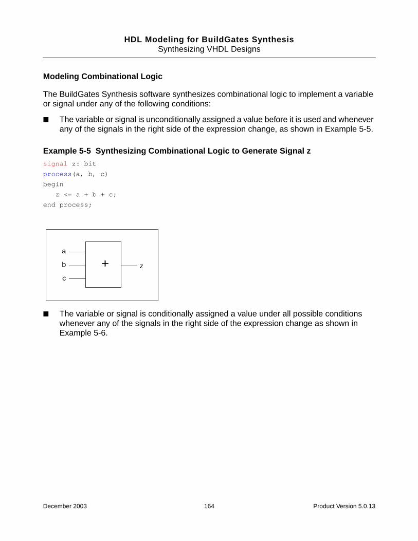
HDL Modeling for BuildGates SynthesisSynthesizing VHDL Designs
Modeling Combinational Logic
The BuildGates Synthesis software synthesizes combinational logic to implement a variableor signal under any of the following conditions:
■ The variable or signal is unconditionally assigned a value before it is used and wheneverany of the signals in the right side of the expression change, as shown in Example 5-5.
Example 5-5 Synthesizing Combinational Logic to Generate Signal zsignal z: bit
process(a, b, c)
begin
z <= a + b + c;
end process;
■ The variable or signal is conditionally assigned a value under all possible conditionswhenever any of the signals in the right side of the expression change as shown inExample 5-6.
a
b
c
z+
December 2003 164 Product Version 5.0.13
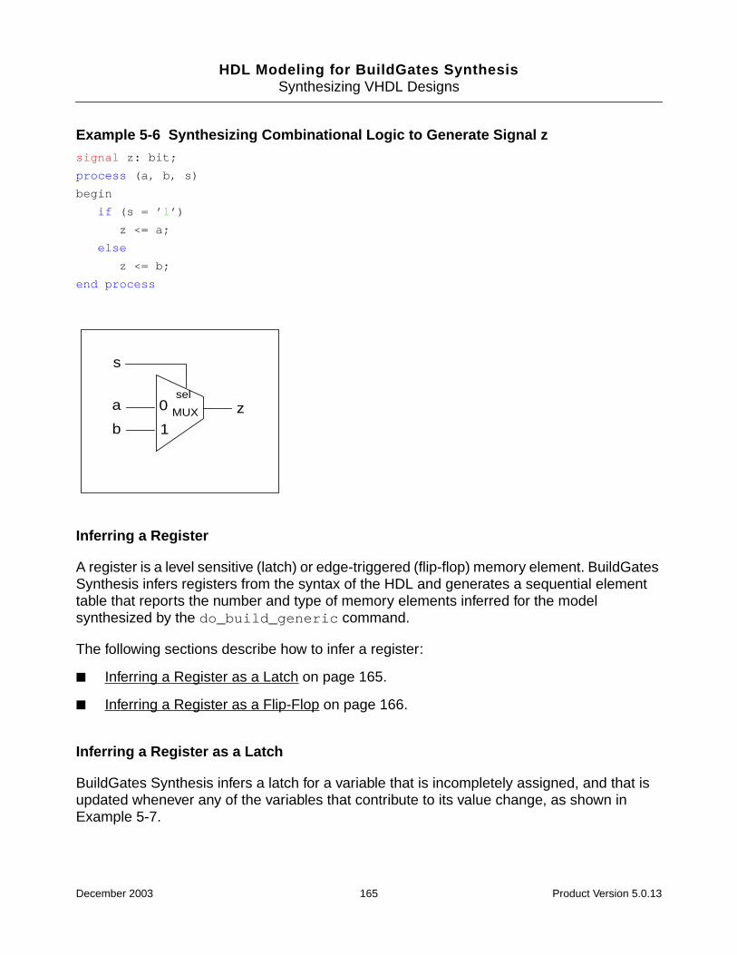
HDL Modeling for BuildGates SynthesisSynthesizing VHDL Designs
Example 5-6 Synthesizing Combinational Logic to Generate Signal zsignal z: bit;
process (a, b, s)
begin
if (s = ’1’)
z <= a;
else
z <= b;
end process
Inferring a Register
A register is a level sensitive (latch) or edge-triggered (flip-flop) memory element. BuildGatesSynthesis infers registers from the syntax of the HDL and generates a sequential elementtable that reports the number and type of memory elements inferred for the modelsynthesized by the do_build_generic command.
The following sections describe how to infer a register:
■ Inferring a Register as a Latch on page 165.
■ Inferring a Register as a Flip-Flop on page 166.
Inferring a Register as a Latch
BuildGates Synthesis infers a latch for a variable that is incompletely assigned, and that isupdated whenever any of the variables that contribute to its value change, as shown inExample 5-7.
a
bzMUX
s
0
1
sel
December 2003 165 Product Version 5.0.13
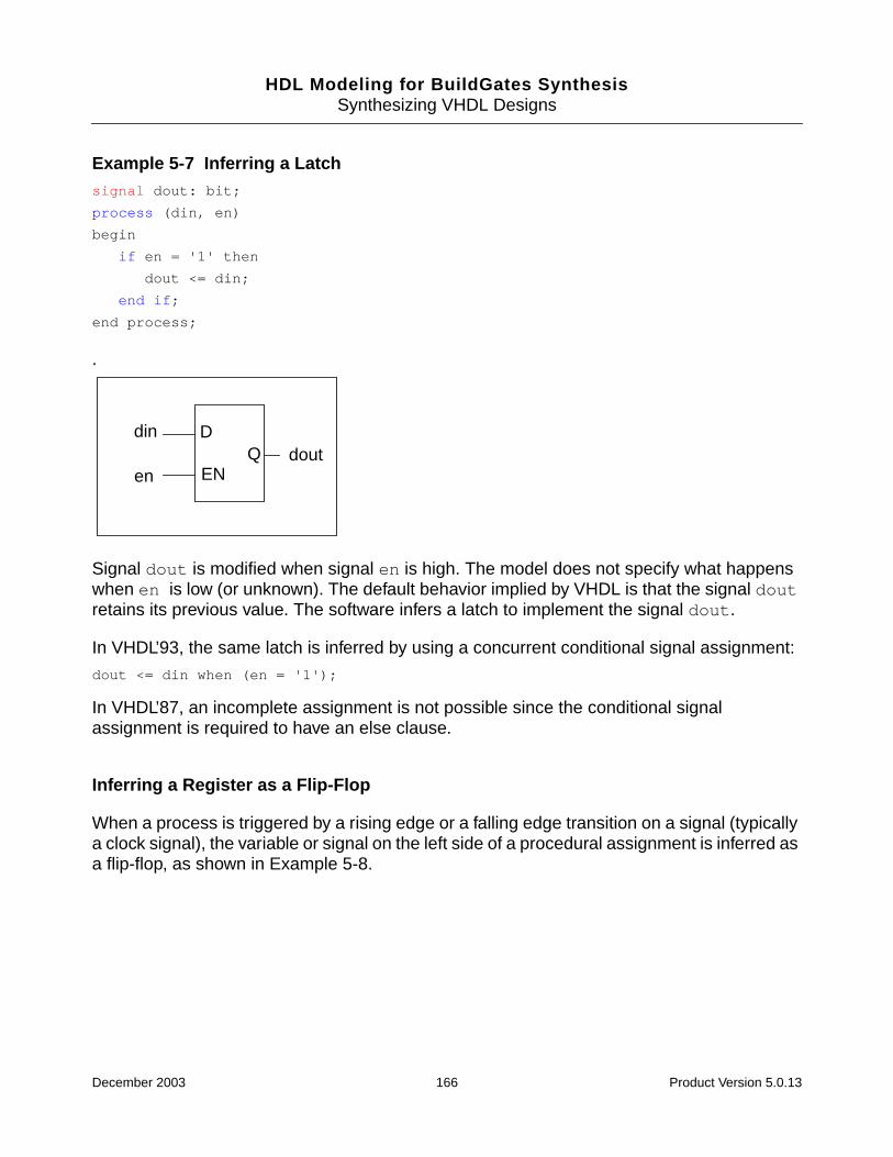
HDL Modeling for BuildGates SynthesisSynthesizing VHDL Designs
Example 5-7 Inferring a Latchsignal dout: bit;
process (din, en)
begin
if en = '1' then
dout <= din;
end if;
end process;
.
Signal dout is modified when signal en is high. The model does not specify what happenswhen en is low (or unknown). The default behavior implied by VHDL is that the signal doutretains its previous value. The software infers a latch to implement the signal dout.
In VHDL’93, the same latch is inferred by using a concurrent conditional signal assignment:
dout <= din when (en = '1');
In VHDL’87, an incomplete assignment is not possible since the conditional signalassignment is required to have an else clause.
Inferring a Register as a Flip-Flop
When a process is triggered by a rising edge or a falling edge transition on a signal (typicallya clock signal), the variable or signal on the left side of a procedural assignment is inferred asa flip-flop, as shown in Example 5-8.
din
endout
D
ENQ
December 2003 166 Product Version 5.0.13

HDL Modeling for BuildGates SynthesisSynthesizing VHDL Designs
Example 5-8 Inferring a Flip-Flopsignal dout: bit;
process (clk)
begin
if (clk'event and clk = '1') then
dout <= din;
end if;
end process;
A rising-edge-triggered D-type flip-flop is inferred when data input is connected to din, clockinput is connected to clk, and output is connected to dout.
In VHDL’93, the same flip-flop can be modeled by using a concurrent conditional signalassignment:
dout <= din when rising_edge(clk);
Note: This model uses the standard rising_edge function (defined in packagesIEEE.STD_LOGIC_1164 and IEEE.NUMERIC_BIT) to specify a positive edge on signalclk.
din doutD
CLK
Q
clk
December 2003 167 Product Version 5.0.13
HDL Modeling for BuildGates SynthesisSynthesizing VHDL Designs
Example 5-9 Synthesizing a Synchronous set and reset Signals On a Flip-Flopprocess(clk)
begin
if (clk'event and clk = '1') then
if set = '1' then
dout <= '1';
elsif reset = '1' then
dout <= '0';
else
dout <= din;
end if;
end if;
end process;
The process is triggered only on the rising edge of clk, but the assignment to dout iscontrolled by set and reset signals; dout is assigned the value of din only when set andreset are inactive.
Only single-bit set and reset signals are supported. See VHDL Synthesis Directives onpage 174 for more information on controlling the set and reset connections for a flip-flop.
Use the model, shown in Example 5-10, to synthesize a flip-flop with asynchronous set andreset connections.
Example 5-10 Synthesizing Asynchronous set and reset Signals On a Flip-Flopprocess(clk, rst)
begin
if set = ’1’ then
dout <= ’1’;
elsif reset = ’1’ then
dout <= ’0’;
elsif (clk’event and clk = ’1’) then
dout <= din;
end if;
end process;
The process is triggered when a rising edge is detected on clk or a change is detected onset or reset. If set or reset is active low, then the condition in the if statement iscanceled. For example:
December 2003 168 Product Version 5.0.13
HDL Modeling for BuildGates SynthesisSynthesizing VHDL Designs
process(clk, set, ...)
begin
if set = '0' then
dout <= '1';
Specifying Clock Edges for Flip-Flops
■ Using an if statement:
process (clk)
begin
if (clk'event and clk = '1') then
dout <= din;
end if;
end process
■ Using a wait statement:
process
begin
wait until (clk'event and clk = '1');
dout <= din;
end process;
■ Using a conditional signal assignment statement in VHDL’93:
dout <= din when (clk'event and clk = '1');
Specifying Clock Signals for Flip-Flops
Specify the rising edge of the clock signal in the following ways:
■ For bit clock signals:
❑ clk'event and clk = '1'
❑ not clk'stable and clk = '1'
■ For boolean clock signals:
❑ clk'event and clk = TRUE
❑ not clk'stable and clk = TRUE
■ For std_ulogic and std_logic clock signals:
❑ rising_edge(clk)
December 2003 169 Product Version 5.0.13
HDL Modeling for BuildGates SynthesisSynthesizing VHDL Designs
❑ clk'event and clk = '1'
❑ not clk'stable and clk = '1'
Specify the falling edge of the clock signal in the following ways:
■ For bit clock signals:
❑ clk'event and clk = '0'
❑ not clk'stable and clk = '0'
■ For boolean clock signals:
❑ clk'event and clk = FALSE
❑ not clk'stable and clk = FALSE
■ For std_ulogic and std_logic clock signals:
❑ falling_edge(clk)
❑ clk'event and clk = '0'
❑ not clk'stable and clk = '0'
All of these clock edge expressions can be used in if, wait, and conditional signalassignment statements.
In addition, the following expressions can be used in wait statements to specify rising andfalling edges respectively:
■ wait until (clk = '1'); -- rising clock edge
■ wait until (clk = '0'); -- falling clock edge
Using case Statements to Infer Registers
Using a case statement allows for multi-way branching in a functional description. When acase statement is used as a decoder to assign one of several different values to a variable,the logic can be implemented as combinational or sequential logic based on whether thesignal or variable is assigned a value in branches of the case statement. Use a casestatement in one of two ways when inferring a register:
■ Using an Incomplete case Statement to Infer a Latch on page 171
■ Using a Complete case Statement to Prevent a Latch on page 171
December 2003 170 Product Version 5.0.13
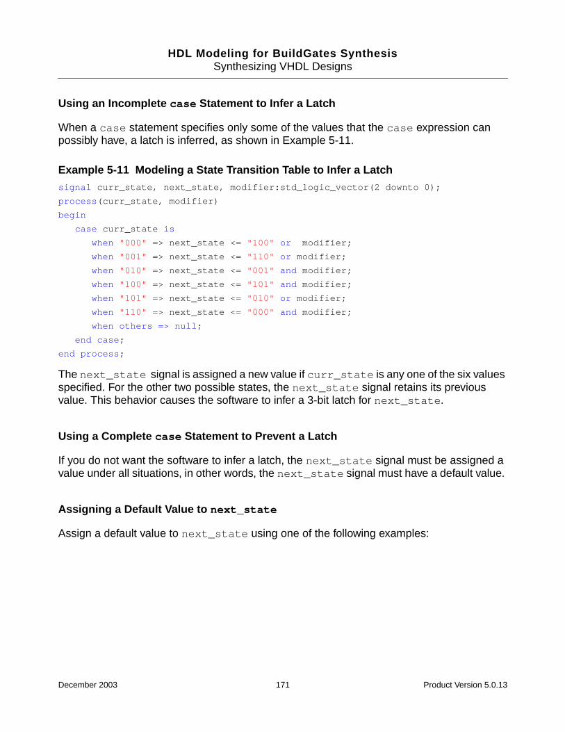
HDL Modeling for BuildGates SynthesisSynthesizing VHDL Designs
Using an Incomplete case Statement to Infer a Latch
When a case statement specifies only some of the values that the case expression canpossibly have, a latch is inferred, as shown in Example 5-11.
Example 5-11 Modeling a State Transition Table to Infer a Latchsignal curr_state, next_state, modifier:std_logic_vector(2 downto 0);
process(curr_state, modifier)
begin
case curr_state is
when "000" => next_state <= "100" or modifier;
when "001" => next_state <= "110" or modifier;
when "010" => next_state <= "001" and modifier;
when "100" => next_state <= "101" and modifier;
when "101" => next_state <= "010" or modifier;
when "110" => next_state <= "000" and modifier;
when others => null;
end case;
end process;
The next_state signal is assigned a new value if curr_state is any one of the six valuesspecified. For the other two possible states, the next_state signal retains its previousvalue. This behavior causes the software to infer a 3-bit latch for next_state.
Using a Complete case Statement to Prevent a Latch
If you do not want the software to infer a latch, the next_state signal must be assigned avalue under all situations, in other words, the next_state signal must have a default value.
Assigning a Default Value to next_state
Assign a default value to next_state using one of the following examples:
December 2003 171 Product Version 5.0.13
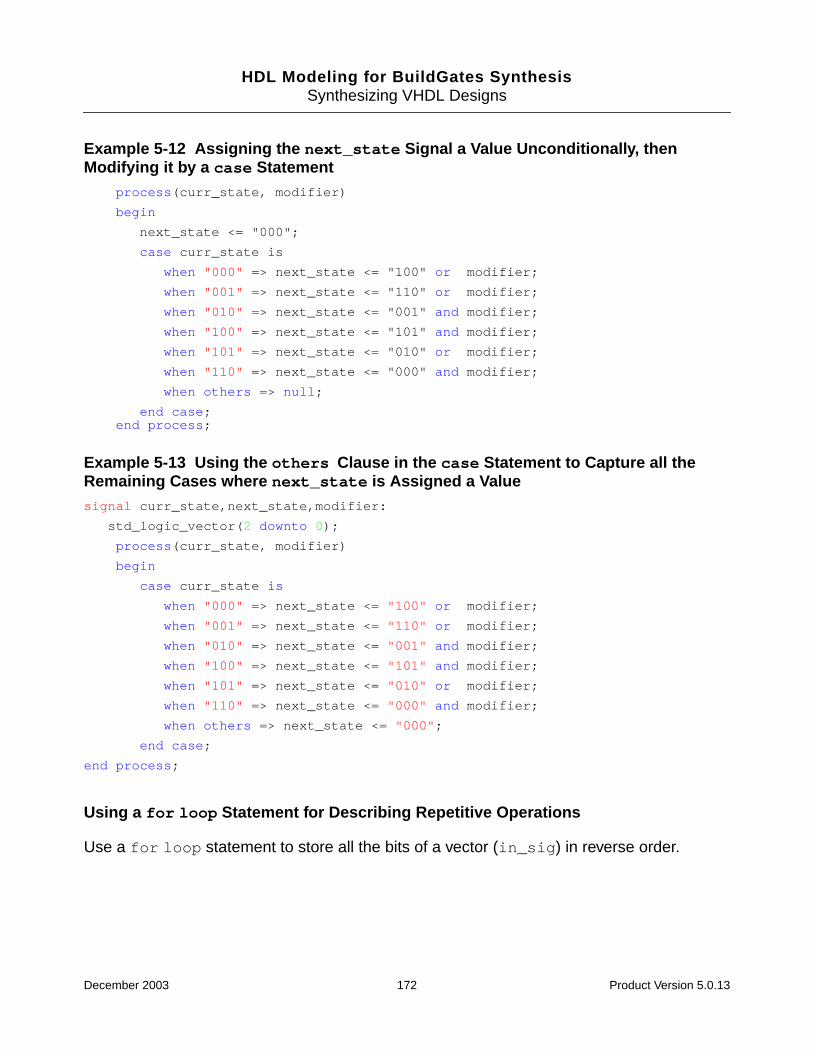
HDL Modeling for BuildGates SynthesisSynthesizing VHDL Designs
Example 5-12 Assigning the next_state Signal a Value Unconditionally, thenModifying it by a case Statement
process(curr_state, modifier)
begin
next_state <= "000";
case curr_state is
when "000" => next_state <= "100" or modifier;
when "001" => next_state <= "110" or modifier;
when "010" => next_state <= "001" and modifier;
when "100" => next_state <= "101" and modifier;
when "101" => next_state <= "010" or modifier;
when "110" => next_state <= "000" and modifier;
when others => null;
end case;end process;
Example 5-13 Using the others Clause in the case Statement to Capture all theRemaining Cases where next_state is Assigned a Valuesignal curr_state,next_state,modifier:
std_logic_vector(2 downto 0);
process(curr_state, modifier)
begin
case curr_state is
when "000" => next_state <= "100" or modifier;
when "001" => next_state <= "110" or modifier;
when "010" => next_state <= "001" and modifier;
when "100" => next_state <= "101" and modifier;
when "101" => next_state <= "010" or modifier;
when "110" => next_state <= "000" and modifier;
when others => next_state <= "000";
end case;
end process;
Using a for loop Statement for Describing Repetitive Operations
Use a for loop statement to store all the bits of a vector (in_sig) in reverse order.
December 2003 172 Product Version 5.0.13
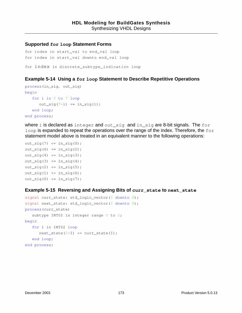
HDL Modeling for BuildGates SynthesisSynthesizing VHDL Designs
Supported for loop Statement Formsfor index in start_val to end_val loop
for index in start_val downto end_val loop
for index in discrete_subtype_indication loop
Example 5-14 Using a for loop Statement to Describe Repetitive Operationsprocess(in_sig, out_sig)
begin
for i in 0 to 7 loop
out_sig(7-i) <= in_sig(i);
end loop;
end process;
where i is declared as integer and out_sig and in_sig are 8-bit signals. The forloop is expanded to repeat the operations over the range of the index. Therefore, the forstatement model above is treated in an equivalent manner to the following operations:
out_sig(7) <= in_sig(0);
out_sig(6) <= in_sig(2);
out_sig(4) <= in_sig(3);
out_sig(3) <= in_sig(4);
out_sig(2) <= in_sig(5);
out_sig(1) <= in_sig(6);
out_sig(0) <= in_sig(7);
Example 5-15 Reversing and Assigning Bits of curr_state to next_state
signal curr_state: std_logic_vector(2 downto 0);
signal next_state: std_logic_vector(2 downto 0);
process(curr_state)
subtype INT02 is integer range 0 to 2;
begin
for I in INT02 loop
next_state(2-I) <= curr_state(I);
end loop;
end process;
December 2003 173 Product Version 5.0.13
HDL Modeling for BuildGates SynthesisSynthesizing VHDL Designs
VHDL Synthesis Directives
Synthesis directives perform code selection or specify how the set and reset pins of aregister are wired. Two forms of VHDL synthesis directives are supported:
■ Attributes—Defines VHDL attributes attached to appropriate objects in the source VHDL.
■ Meta-comment—Defines the VHDL comments embedded in the VHDL source code.These directives begin with the keyword ambit synthesis.
Note: If you use a comment to specify a synthesis directive, that comment should not containany extra characters other than what is necessary for the synthesis directive.
This section describes the following synthesis directives:
■ Code Selection Directives on page 175
❑ Synthesis On and Synthesis Off Directives on page 175
❑ Translate On and Translate Off Directives on page 175
■ Architecture Selection Directive on page 176
■ case Statement Directive on page 177
■ Enumeration Encoding Directive on page 177
■ Entity Template Directive on page 178
■ Function and Task Mapping Directives on page 178
■ Signed Type Directive on page 179
■ Resolution Function Directives on page 179
■ Type Conversion Directives on page 180
■ Set and Reset Synthesis Directives on page 181
❑ Process Directives on page 183
❑ Signal Directives on page 186
■ Operator Merging Directive on page 190
■ Supported Synopsys Directives on page 191
December 2003 174 Product Version 5.0.13

HDL Modeling for BuildGates SynthesisSynthesizing VHDL Designs
Code Selection Directives
By default, BuildGates Synthesis compiles all VHDL code from a file. Use the code selectionsynthesis directives in pairs around VHDL code that should not be compiled for synthesis.
Synthesis On and Synthesis Off Directives
All the code following the synthesis directive -- ambit synthesis off up to and includingthe synthesis directive -- ambit synthesis on is ignored by the tool. However, the codebetween the two directives will be checked for syntactic correctness.
You can add assertions in your model that are not synthesized for debugging purposes. If theassertions are surrounded by the synthesis on and synthesis off directives, the toolignores them for synthesis but verifies the syntax between the directives.
Example 5-16 Using Synthesis On and Off Directivesfunction DIVIDE (L, R: integer) return integer
is variable RESULT: integer;
begin
-- ambit synthesis off
assert (R /= 0)
report "Attempt to Divide by Zero Unsupported !!!"
severity ERROR;
-- ambit synthesis on
RESULT:= L/R;
return (RESULT);
end DIVIDE;
Translate On and Translate Off Directives
The translate on and translate off code selection directives are used around VHDLcode that should be completely ignored by the VHDL parser and not synthesized by the tool.All the code following the synthesis directive ambit translate off up to and including thesynthesis directive ambit translate on is ignored by the tool even if it contains syntaxerrors.
December 2003 175 Product Version 5.0.13
HDL Modeling for BuildGates SynthesisSynthesizing VHDL Designs
Architecture Selection Directive
Use this directive to select different types of architectures for arithmetic and comparator(relational) operators. The architectures available are based on whether you have purchasedBuildGates Extreme which comes with Datapath. For information on Datapath, refer toDatapath for BuildGates Synthesis and PKS.
The standard BuildGates Synthesis software without Datapath contains the following finaladder architectures:
■ cla (carry lookahead)
■ ripple (ripple carry)
BuildGates Synthesis, with Datapath Synthesis of BuildGates Synthesis and CadencePhysically Knowledgeable Synthesis (PKS), contains the following final adder and multiplierencoding architectures:
Datapath final adder architectures:
■ fcla (fast carry lookahead)
■ cla (carry lookahead)
■ csel (carry select)
■ ripple (ripple carry)
Datapath multiplier encoding architectures:
■ non-booth
■ booth
For VHDL, specify the architecture selection directive immediately after the selected operatoris used, as shown in Example 5-17.
Example 5-17 Using the Architecture Selection Directive for VHDL-- use Ripple Carry adder
x <= a + b; -- ambit synthesis architecture = ripple
If there are multiple operators in the expression, place the directive after the desired operator,as shown in Example 5-18.
December 2003 176 Product Version 5.0.13
HDL Modeling for BuildGates SynthesisSynthesizing VHDL Designs
Example 5-18 Using the Architecture Selection Directive for Multiple Operators-- implement subtractor with ripple-carry architecture
x1 <= a + b - c; -- ambit synthesis architecture = ripple
-- implement adder with ripple-carry and substractor
-- with carry lookahead architecture
x2 <= a + -- ambit synthesis architecture = ripple
b - c; -- ambit synthesis architecture = cla
case Statement Directive
If you use a case statement as a multiplexer instead of random logic, then the mux directiveshould be specified for the case statement, as shown in Example 5-19.
Example 5-19 Using the case Statement Directiveprocess(d, s)
begin
case (s) is -- ambit synthesis mux
when "000" => z <= d(0);
when "001" => z <= d(1);
when "010" => z <= d(2);
when "011" => z <= d(3);
when "100" => z <= d(4);
when "101" => z <= d(5);
-- "110" not specified.
when "111" => z <= d(7);
when others => null;
end case;
end process;
Enumeration Encoding Directive
Use this directive to override the default encoding of enumeration literals. In Example 5-20,the literals RED and YELLOW would normally be encoded as 00 and 11, respectively(corresponding to their position in the type COLOR, starting from 0). Because of theENUM_ENCODING attribute, RED and YELLOW are encoded as 10 and 01, respectively. Theattribute ENUM_ENCODING is declared in the package: ambit.attributes.
The ENUM_ENCODING value string must contain as many encodings as there are literals inthe corresponding enumeration type. All encodings contain only 0’s or 1’s and should havean identical number of bits.
December 2003 177 Product Version 5.0.13
HDL Modeling for BuildGates SynthesisSynthesizing VHDL Designs
Example 5-20 Using the Enumeration Encoding Directivetype COLOR is (RED, BLUE, GREEN, YELLOW);
attribute ENUM_ENCODING: string;
attribute ENUM_ENCODING of COLOR: type is "10 00 11 01”;
Entity Template Directive
When an entity is written with generic declarations for use as a template, only the instantiated,parameterized design needs to be synthesized. Use the TEMPLATE directive on an entity toindicate that the template entity is not to be synthesized except in the context of aninstantiation from a higher level module, never as a top-level entity. Specify the TEMPLATEdirective as TRUE in the entity declaration as shown in Example 5-21.
Example 5-21 Using the Entity Template Directiveuse ambit.attributes.all;
entity FOO is
generic (Width : integer := 64);
port (DIN : bit_vector (Width - 1 downto 0);
DOUT : bit_vector (Width - 1 downto 0));
attribute TEMPLATE of FOO: entity is TRUE;
end FOO;
The do_build_generic command runs faster by designating entities as templates. Iteliminates synthesizing the template entities that are not actually used in the hierarchicaldesign as stand-alone modules. The attribute TEMPLATE is declared in the followingpackage: ambit.attributes.
Function and Task Mapping Directives
Use the map_to_module directive in functions and tasks, and use the return_port_namedirective only in functions. These directives should appear within the declaration of a task orfunction. For example:
-- ambit synthesis map_to_module module_name
The map_to_module directive specifies that any call to the given function or task is to beinternally mapped to an instantiation of the specified module. The statements in the functionor task body are therefore ignored. Arguments to the function or task are mapped positionallyonto ports in the module. For example:
-- ambit synthesis return_port_name port_name
December 2003 178 Product Version 5.0.13

HDL Modeling for BuildGates SynthesisSynthesizing VHDL Designs
Use the return_port_name directive with functions. This directive applies only to a functionto which the map_to_module directive is in effect, and specifies that the return value for thefunction call is given by the output port of the mapped-to module.
The following code, shown in Example 5-22, maps a function to entity BUF with output z:
Example 5-22 Using the Function and Task Mapping Directivesfunction f(d : in std_logic) return std_logic is
-- ambit synthesis map_to_module BUF
-- ambit synthesis return_port_name z
begin
return d;
end;
The following entity instantiation:
i1 : entity work.BUF port map(z, d);
is equivalent to the following function call:
q <= f(d);
Signed Type Directive
Use this directive to specify that the annotated vector type is to be treated like a signed typefor all arithmetic, logical, and relational operations. The attribute SIGNED_TYPE is a Boolean-valued attribute declared in the package: ambit.attributes.
Example 5-23 shows the ieee.numeric_std.signed type.
Example 5-23 Using the Signed Type Directiveuse ambit.attributes.all;
....
type SIGNED is array (NATURAL range <>) of STD_LOGIC;
-- Attribute the type ’SIGNED’ for synthesis
attribute SIGNED_TYPE of SIGNED : type is TRUE;
Resolution Function Directives
Use the RESOLUTON function directives to identify and define the intended behavior of aresolution function in the design.
December 2003 179 Product Version 5.0.13
HDL Modeling for BuildGates SynthesisSynthesizing VHDL Designs
Define the resolution by specifying the string-valued attribute RESOLUTION to control how asignal (with multiple drivers and resolved by the attributed function) is synthesized.
The following directives will cause a WIRED_AND, WIRED_OR, or WIRED_TRI (three-state)behavior to be synthesized for any signal that is resolved by function MYRES:
attribute RESOLUTION: string;
attribute RESOLUTION of MYRES: function is "WIRED_AND";
attribute RESOLUTION of MYRES: function is "WIRED_OR";
attribute RESOLUTION of MYRES: function is "WIRED_TRI";
In Example 5-24, the function MYRES has been tagged as having WIRED_OR behavior usingthe RESOLUTION attribute. signal X with resolution function MYRES is synthesized toexhibit a WIRED_OR behavior.
Example 5-24 Using the Resolution Function Directivefunction MYRES(bv: bit_vector) return ulogic_4 is variable tmp: bit:= '0';
begin
for I in vtbr'range loop
tmp:= tmp or bv(I);
end loop;
return tmp;
end;
attribute RESOLUTION of MYRES: function is "WIRED_OR";
signal X: MYRES bit;
The attribute RESOLUTION is declared in the package ambit.attributes.
Type Conversion Directives
Use the TYPE_CONVERSION directives to translate between unrelated user-defined types.The type conversion directive behaves like an identity operator; the body of such a functiondoes not need to be synthesized.
There are three types of type conversion directives that can be attached to a function body:
■ -- ambit synthesis BUILTIN_TYPE_CONVERSION
■ -- ambit synthesis BUILTIN_ZERO_EXTEND
■ -- ambit synthesis BUILTIN_SIGN_EXTEND
December 2003 180 Product Version 5.0.13
HDL Modeling for BuildGates SynthesisSynthesizing VHDL Designs
When you use these directives, the function body is ignored by the synthesis tool. TheBUILTIN_TYPE_CONVERSION directive is used for converting between identically sizedtypes, such as between bit_vector (0 to 7) and std_logic_vector (0 to 7).
Use the BUILTIN_ZERO_EXTEND and BUILTIN_SIGN_EXTEND directives for conversionswhere the size of the argument and returned value are different.
Example 5-25 treats the translate function as an identity operator.
Example 5-25 Using the Type Conversion Directivesfunction translate(b: bit) return integer is
-- ambit synthesis BUILTIN_TYPE_CONVERSION
begin
if (b = '0') then
return 0;
else
return 1;
end if;
end function;
Set and Reset Synthesis Directives
When the do_build_generic command infers a register from a VHDL description, it alsoinfers set and reset control of the register, and defines whether these controls aresynchronous or asynchronous. For examples showing flip-flops and latches with set and resetoperations, see Inferring a Register on page 165.
There are two ways to implement the synchronous set and reset logic for these inferredregisters:
■ Control the Input to the Data Pin – Controls the input to the data pin of a registercomponent using set and reset logic so that the data value is 1 when set is active, 0when reset is active, and driven by the data source when both set and reset areinactive. This is the default approach. Figure 5-2 shows the default implementation of theset and reset control logic.
■ Implement set and reset Control – Implements set and reset control of a registerby selecting the appropriate register component (cell) from the technology library andconnecting the output of set and reset logic directly to the set and reset pins of thecomponent. The data pin of the component is driven directly by the data source.Figure 5-3 shows the implementation of the set and reset control logic.
December 2003 181 Product Version 5.0.13
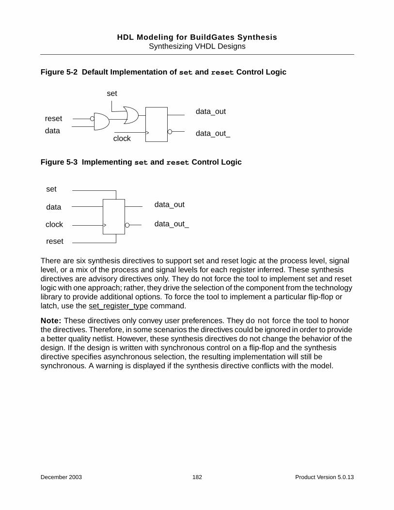
HDL Modeling for BuildGates SynthesisSynthesizing VHDL Designs
Figure 5-2 Default Implementation of set and reset Control Logic
Figure 5-3 Implementing set and reset Control Logic
There are six synthesis directives to support set and reset logic at the process level, signallevel, or a mix of the process and signal levels for each register inferred. These synthesisdirectives are advisory directives only. They do not force the tool to implement set and resetlogic with one approach; rather, they drive the selection of the component from the technologylibrary to provide additional options. To force the tool to implement a particular flip-flop orlatch, use the set_register_type command.
Note: These directives only convey user preferences. They do not force the tool to honorthe directives. Therefore, in some scenarios the directives could be ignored in order to providea better quality netlist. However, these synthesis directives do not change the behavior of thedesign. If the design is written with synchronous control on a flip-flop and the synthesisdirective specifies asynchronous selection, the resulting implementation will still besynchronous. A warning is displayed if the synthesis directive conflicts with the model.
set
reset
dataclock
data_out
data_out_
clock
set
reset
data data_out
data_out_
December 2003 182 Product Version 5.0.13

HDL Modeling for BuildGates SynthesisSynthesizing VHDL Designs
Process Directives
Use the process (or block) directives to control the connection of set and reset control logicfor all the registers inferred within a specific process. Specify process directives usingBoolean-valued attributes attached directly on the labels of the specific process as shownbelow:
attribute SYNC_SET_RESET_PROCESS: boolean;
attribute SYNC_SET_RESET_PROCESS of P1: label is TRUE;
attribute ASYNC_SET_RESET_PROCESS: boolean;
attribute ASYNC_SET_RESET_PROCESS of P2: label is TRUE;
P1 and P2 are the labels of the processes. These directives indicate that the set and resetcontrol logic for all the registers inferred within the process is directly connected to thesynchronous (for SYNC_SET_RESET_PROCESS) and asynchronous (forASYNC_SET_RESET_PROCESS) pins of the register component. The attributesSYNC_SET_RESET_PROCESS and ASYNC_SET_RESET_PROCESS are declared in thepackage: ambit.attributes.
Note: These process directives must be specified in the declarative region of thearchitecture that contains the process being attributed. An error results if you specify theseprocess directives for non-existent processes.
In Example 5-26 out1 is inferred as a D-type flip-flop with synchronous connections to setand reset pins, but out2 is inferred as a D-type flip-flop with synchronous reset and setoperations controlled through combinational logic feeding the data port D, as shown inFigure 5-4.
December 2003 183 Product Version 5.0.13
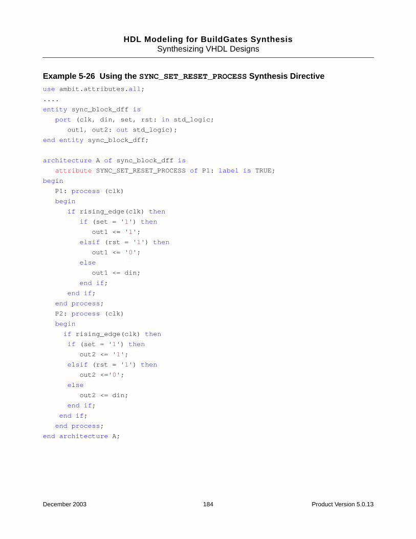
HDL Modeling for BuildGates SynthesisSynthesizing VHDL Designs
Example 5-26 Using the SYNC_SET_RESET_PROCESS Synthesis Directiveuse ambit.attributes.all;
....
entity sync_block_dff is
port (clk, din, set, rst: in std_logic;
out1, out2: out std_logic);
end entity sync_block_dff;
architecture A of sync_block_dff is
attribute SYNC_SET_RESET_PROCESS of P1: label is TRUE;
begin
P1: process (clk)
begin
if rising_edge(clk) then
if (set = '1') then
out1 <= '1';
elsif (rst = '1') then
out1 <= '0';
else
out1 <= din;
end if;
end if;
end process;
P2: process (clk)
begin
if rising_edge(clk) then
if (set = '1') then
out2 <= '1';
elsif (rst = '1') then
out2 <='0';
else
out2 <= din;
end if;
end if;
end process;
end architecture A;
December 2003 184 Product Version 5.0.13
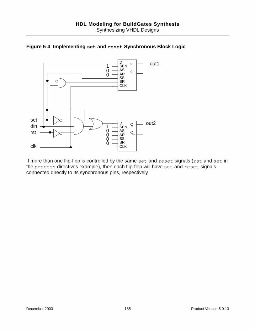
HDL Modeling for BuildGates SynthesisSynthesizing VHDL Designs
Figure 5-4 Implementing set and reset Synchronous Block Logic
If more than one flip-flop is controlled by the same set and reset signals (rst and set inthe process directives example), then each flip-flop will have set and reset signalsconnected directly to its synchronous pins, respectively.
DSENASARSSSRCLK
Q
Q_
DSENASARSSSRCLK
Q
Q_
setdinrst
clk
100
10000
out1
out2
December 2003 185 Product Version 5.0.13

HDL Modeling for BuildGates SynthesisSynthesizing VHDL Designs
Signal Directives
Use signal directives to selectively connect some of the signals directly to the set or resetpin of the component and let the other signals propagate through logic onto the data pin.
The signal directive states that the specified signal should be connected directly to the setand reset pin of any inferred registers for which the signal causes a set or reset. Specify thesignal directive using Boolean-valued attributes attached directly to the appropriate signals,as shown below:
attribute SYNC_SET_RESET: boolean;
attribute SYNC_SET_RESET of S: signal is true;
attribute ASYNC_SET_RESET: boolean;
attribute ASYNC_SET_RESET of R: signal is true;
The signals are tagged S and R with the attribute SYNC_SET_RESET andASYNC_SET_RESET, respectively, indicating that they should be connected directly to thesynchronous set and asynchronous reset pins of the inferred registers. The attributesSYNC_SET_RESET and ASYNC_SET_RESET are declared in the package:ambit.attributes.
Note: The signal directive must be specified in the same declarative region as the signalbeing attributed. An error occurs if you specify these directives for a non-existent or unusedsignal.
The flip-flop inferred for out1 and out2, shown in Example 5-27 is connected so that theset signal connects to the synchronous set pin and the reset signal is connected throughcombinational logic feeding the data port D. The generated logic is shown in Figure 5-5.
December 2003 186 Product Version 5.0.13

HDL Modeling for BuildGates SynthesisSynthesizing VHDL Designs
Example 5-27 Using the Signal Directiveuse ambit.attributes.all;
....
entity sync_sig_dff is
port (clk, din, set1, rst1, set2, rst2: in std_logic;
out1, out2: out std_logic);
attribute SYNC_SET_RESET of set1: signal is true;
attribute SYNC_SET_RESET of set2: signal is true;
end entity sync_sig_dff;
architecture A of sync_sig_dff is
begin
P1: process (clk)
begin
if rising_edge(clk) then
if (set1 = '1') then
out1 <= '1';
elsif (rst1 = '1') then
out1 <= '0';
else
out1 <= din;
end if;
end if;
end process;
P2: process (clk)
begin
if rising_edge(clk) then
if (set2 = '1') then
out2 <= '1';
elsif (rst2 = '1') then
out2 <= '0';
else
out2 <= din;
end if;
end if;
end process;
end architecture A;
December 2003 187 Product Version 5.0.13

HDL Modeling for BuildGates SynthesisSynthesizing VHDL Designs
Figure 5-5 Implementing set and reset Synchronous Signal Logic
Signals in a Process Directive
Sometimes it is necessary to connect signals directly to the set and to the reset pins ofcertain registers and through the data input of other registers. In this situation, two synthesisdirectives that provide a combination of the synthesis directives discussed above are useful.These synthesis directive combinations let you specify both the process and the signalnames as follows.
Using the SYNC_RESET_LOCAL and ASYNC_SET_RESET_LOCAL Attributes
The following model uses the SYNC_SET_RESET_LOCAL attribute to indicate that the signalrst should be connected to the synchronous set and reset pins of the register(s) inferredin process P1:
signal rst, set: std_logic;
attribute SYNC_SET_RESET_LOCAL: string;
attribute SYNC_SET_RESET_LOCAL of P1: label is "rst";
attribute ASYNC_SET_RESET_LOCAL: string;
attribute ASYNC_SET_RESET_LOCAL of P2: label is "set";
The ASYNC_SET_RESET_LOCAL attribute indicates that the signal set should be connectedto the asynchronous set or reset pin of the register(s) inferred in P2.
DSENASARSSSRCLK
Q
Q_
DSENASARSSSRCLK
Q
Q_
set2
dinrst2
clk
100
100
0
out1
out2
set1
rst1
0
December 2003 188 Product Version 5.0.13
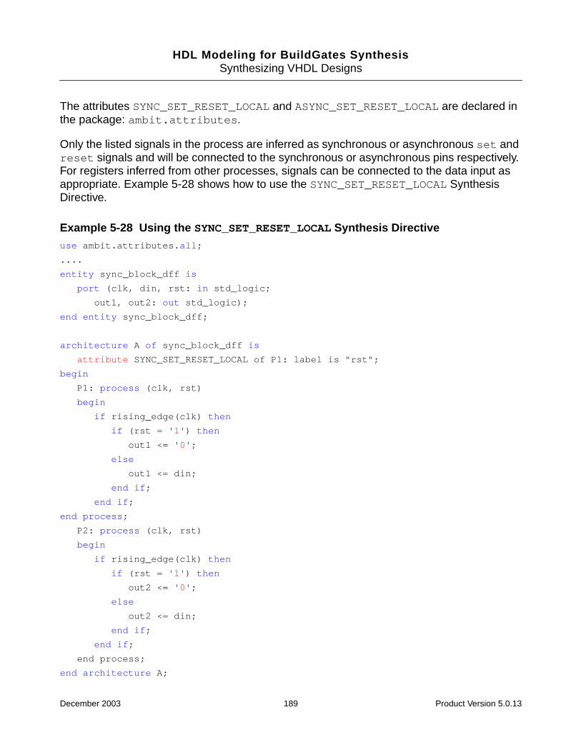
HDL Modeling for BuildGates SynthesisSynthesizing VHDL Designs
The attributes SYNC_SET_RESET_LOCAL and ASYNC_SET_RESET_LOCAL are declared inthe package: ambit.attributes.
Only the listed signals in the process are inferred as synchronous or asynchronous set andreset signals and will be connected to the synchronous or asynchronous pins respectively.For registers inferred from other processes, signals can be connected to the data input asappropriate. Example 5-28 shows how to use the SYNC_SET_RESET_LOCAL SynthesisDirective.
Example 5-28 Using the SYNC_SET_RESET_LOCAL Synthesis Directiveuse ambit.attributes.all;
....
entity sync_block_dff is
port (clk, din, rst: in std_logic;
out1, out2: out std_logic);
end entity sync_block_dff;
architecture A of sync_block_dff is
attribute SYNC_SET_RESET_LOCAL of P1: label is "rst";
begin
P1: process (clk, rst)
begin
if rising_edge(clk) then
if (rst = '1') then
out1 <= '0';
else
out1 <= din;
end if;
end if;
end process;
P2: process (clk, rst)
begin
if rising_edge(clk) then
if (rst = '1') then
out2 <= '0';
else
out2 <= din;
end if;
end if;
end process;
end architecture A;
December 2003 189 Product Version 5.0.13
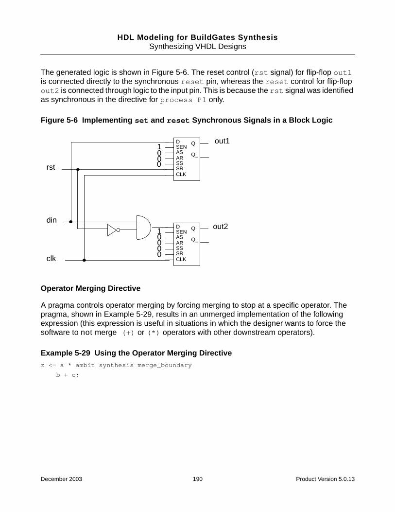
HDL Modeling for BuildGates SynthesisSynthesizing VHDL Designs
The generated logic is shown in Figure 5-6. The reset control (rst signal) for flip-flop out1is connected directly to the synchronous reset pin, whereas the reset control for flip-flopout2 is connected through logic to the input pin. This is because the rst signal was identifiedas synchronous in the directive for process P1 only.
Figure 5-6 Implementing set and reset Synchronous Signals in a Block Logic
Operator Merging Directive
A pragma controls operator merging by forcing merging to stop at a specific operator. Thepragma, shown in Example 5-29, results in an unmerged implementation of the followingexpression (this expression is useful in situations in which the designer wants to force thesoftware to not merge (+) or (*) operators with other downstream operators).
Example 5-29 Using the Operator Merging Directivez <= a * ambit synthesis merge_boundary
b + c;
DSENASARSSSRCLK
Q
Q_
DSENASARSSSRCLK
Q
Q_
din
clk
100
10000
out1
out2
rst 0
December 2003 190 Product Version 5.0.13
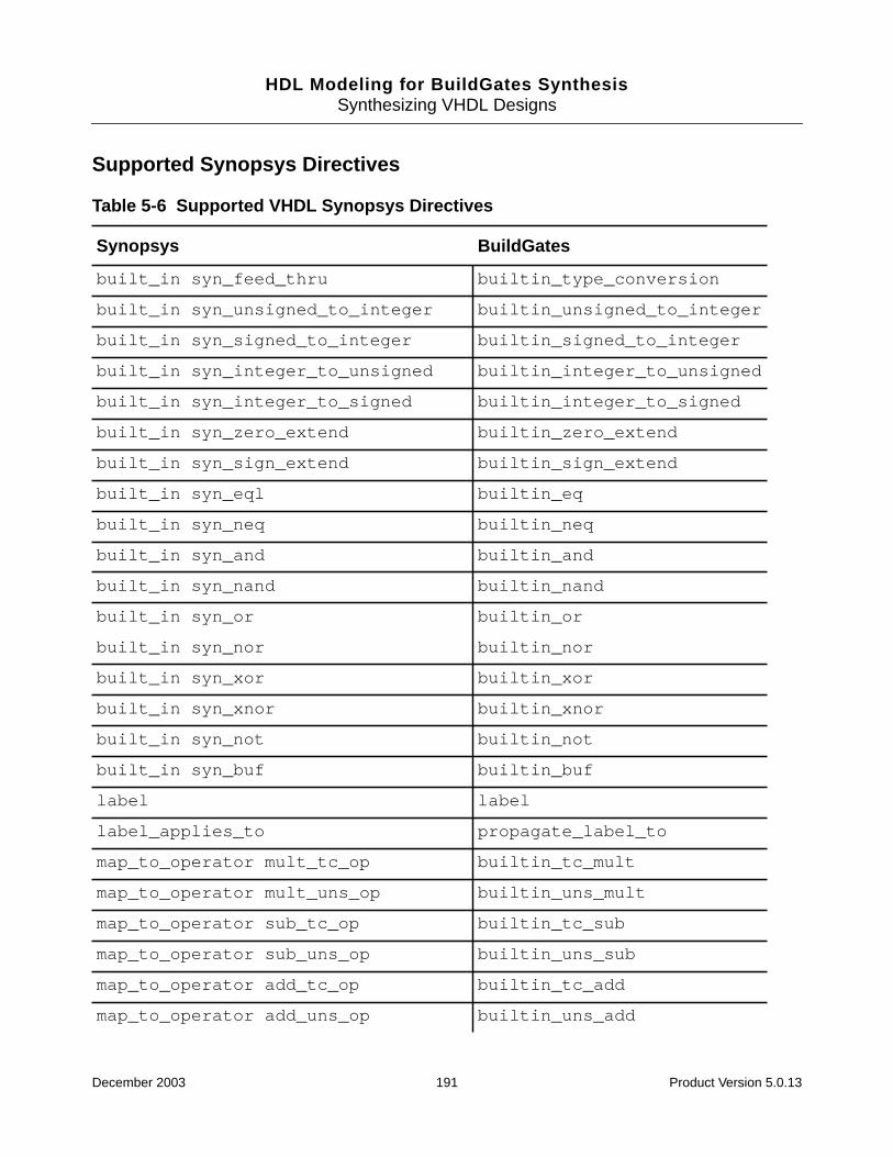
HDL Modeling for BuildGates SynthesisSynthesizing VHDL Designs
Supported Synopsys Directives
Table 5-6 Supported VHDL Synopsys Directives
Synopsys BuildGates
built_in syn_feed_thru builtin_type_conversion
built_in syn_unsigned_to_integer builtin_unsigned_to_integer
built_in syn_signed_to_integer builtin_signed_to_integer
built_in syn_integer_to_unsigned builtin_integer_to_unsigned
built_in syn_integer_to_signed builtin_integer_to_signed
built_in syn_zero_extend builtin_zero_extend
built_in syn_sign_extend builtin_sign_extend
built_in syn_eql builtin_eq
built_in syn_neq builtin_neq
built_in syn_and builtin_and
built_in syn_nand builtin_nand
built_in syn_or builtin_or
built_in syn_nor builtin_nor
built_in syn_xor builtin_xor
built_in syn_xnor builtin_xnor
built_in syn_not builtin_not
built_in syn_buf builtin_buf
label label
label_applies_to propagate_label_to
map_to_operator mult_tc_op builtin_tc_mult
map_to_operator mult_uns_op builtin_uns_mult
map_to_operator sub_tc_op builtin_tc_sub
map_to_operator sub_uns_op builtin_uns_sub
map_to_operator add_tc_op builtin_tc_add
map_to_operator add_uns_op builtin_uns_add
December 2003 191 Product Version 5.0.13
HDL Modeling for BuildGates SynthesisSynthesizing VHDL Designs
map_to_operator lt_tc_op builtin_tc_lt
map_to_operator lt_uns_op builtin_uns_lt
map_to_operator leq_tc_op builtin_tc_lte
map_to_operator leq_uns_op builtin_uns_lte
map_to_module map_to_module
resolution_method wired_or resolution wired_or
resolution_method wired_and resolution wired_and
resolution_method three_state resolution wired_tri
return_port_name return_port_name
synthesis_off synthesis off
synthesis_on synthesis on
translate_off translate off
translate_on translate on
Table 5-6 Supported VHDL Synopsys Directives, continued
Synopsys BuildGates
December 2003 192 Product Version 5.0.13
HDL Modeling for BuildGates SynthesisSynthesizing VHDL Designs
Supported Cadence (Ambit) Directives and BuildGates Equivalents
Table 5-7 Supported Cadence (Ambit) VHDL Directives and BuildGates Equivalents
Cadence (Ambit) BuildGates
translate_off translate off
translate_on translate on
resolution_method wired_and resolution wired_and
resolution_method wired_or resolution wired_or
resolution_method wired_tri_state resolution wired_tri
infer_mux mux
built_in SYN_FEED_THRU BUILTIN_TYPE_CONVERS
built_in SYN_AND BUILTIN_AND
built_in SYN_NAND BUILTIN_NAND
built_in SYN_OR BUILTIN_OR
built_in SYN_NOR BUILTIN_NOR
built_in SYN_XOR BUILTIN_XOR
built_in SYN_XNOR BUILTIN_XNOR
built_in SYN_NOT BUILTIN_NOT
built_in SYN_BUF BUILTIN_BUF
December 2003 193 Product Version 5.0.13
HDL Modeling for BuildGates SynthesisSynthesizing VHDL Designs
Supported BuildGates Synthesis-Only VHDL Directives
Table 5-8 BuildGates-Only VHDL Directives
BuildGates Directive
BUILTIN_OPERATOR
BUILTIN_TC_GT
BUILTIN_UNS_GT
BUILTIN_TC_GTE
BUILTIN_UNS_GTE
BUILTIN_TC_DIV
BUILTIN_UNS_DIV
BUILTIN_SLL
BUILTIN_SRL
BUILTIN_SLA
BUILTIN_SRA
BUILTIN_ROL
BUILTIN_ROR
BUILTIN_TC_MOD
BUILTIN_UNS_MOD
BUILTIN_TC_REM
BUILTIN_UNS_REM
BUILTIN_RISING_EDGE
BUILTIN_FALLING_EDGE
BUILTIN_AND_REDUCE
BUILTIN_NAND_REDUCE
BUILTIN_OR_REDUCE
BUILTIN_NOR_REDUCE
BUILTIN_XOR_REDUCE
BUILTIN_XNOR_REDUCE
December 2003 194 Product Version 5.0.13
HDL Modeling for BuildGates SynthesisSynthesizing VHDL Designs
BUILTIN_STD_MATCH
BUILTIN_BLEND
BUILTIN_COMPGE
BUILTIN_IROUNDMULT
BUILTIN_ITRUNCMULT
BUILTIN_LEADO
BUILTIN_LEAD1
BUILTIN_ROUND
BUILTIN_SAT
BUILTIN_SGNMULT
Table 5-8 BuildGates-Only VHDL Directives
BuildGates Directive
December 2003 195 Product Version 5.0.13
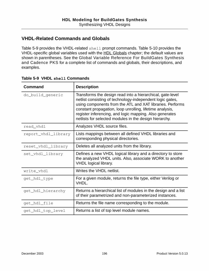
HDL Modeling for BuildGates SynthesisSynthesizing VHDL Designs
VHDL-Related Commands and Globals
Table 5-9 provides the VHDL-related shell prompt commands. Table 5-10 provides theVHDL-specific global variables used with the HDL Globals chapter; the default values areshown in parentheses. See the Global Variable Reference For BuildGates Synthesisand Cadence PKS for a complete list of commands and globals, their descriptions, andexamples.
Table 5-9 VHDL shell Commands
Command Description
do_build_generic Transforms the design read into a hierarchical, gate-levelnetlist consisting of technology-independent logic gates,using components from the ATL and XAT libraries. Performsconstant propagation, loop unrolling, lifetime analysis,register inferencing, and logic mapping. Also generatesnetlists for selected modules in the design hierarchy.
read_vhdl Analyzes VHDL source files.
report_vhdl_library Lists mappings between all defined VHDL libraries andcorresponding physical directories.
reset_vhdl_library Deletes all analyzed units from the library.
set_vhdl_library Defines a new VHDL logical library and a directory to storethe analyzed VHDL units. Also, associate WORK to anotherVHDL logical library.
write_vhdl Writes the VHDL netlist.
get_hdl_type For a given module, returns the file type, either Verilog orVHDL.
get_hdl_hierarchy Returns a hierarchical list of modules in the design and a listof their parametrized and non-parameterized instances.
get_hdl_file Returns the file name corresponding to the module.
get_hdl_top_level Returns a list of top level module names.
December 2003 196 Product Version 5.0.13
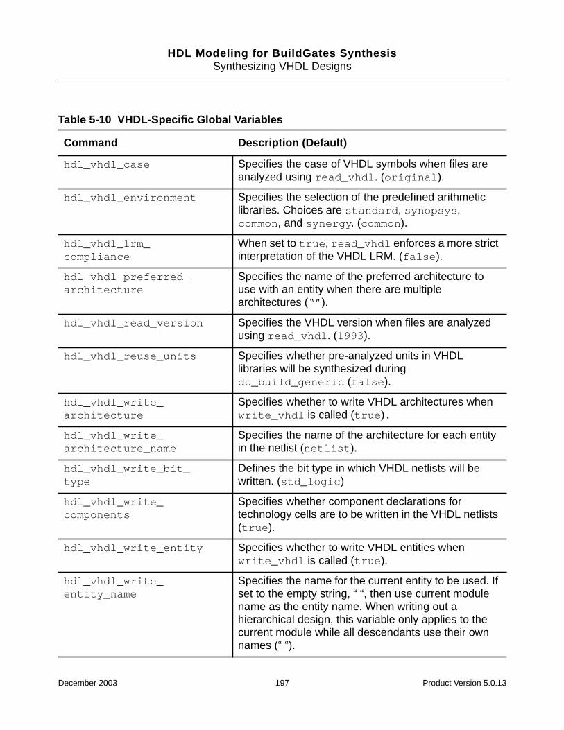
HDL Modeling for BuildGates SynthesisSynthesizing VHDL Designs
Table 5-10 VHDL-Specific Global Variables
Command Description (Default)
hdl_vhdl_case Specifies the case of VHDL symbols when files areanalyzed using read_vhdl. (original).
hdl_vhdl_environment Specifies the selection of the predefined arithmeticlibraries. Choices are standard, synopsys,common, and synergy. (common).
hdl_vhdl_lrm_compliance
When set to true, read_vhdl enforces a more strictinterpretation of the VHDL LRM. (false).
hdl_vhdl_preferred_architecture
Specifies the name of the preferred architecture touse with an entity when there are multiplearchitectures (“”).
hdl_vhdl_read_version Specifies the VHDL version when files are analyzedusing read_vhdl. (1993).
hdl_vhdl_reuse_units Specifies whether pre-analyzed units in VHDLlibraries will be synthesized duringdo_build_generic (false).
hdl_vhdl_write_architecture
Specifies whether to write VHDL architectures whenwrite_vhdl is called (true).
hdl_vhdl_write_architecture_name
Specifies the name of the architecture for each entityin the netlist (netlist).
hdl_vhdl_write_bit_type
Defines the bit type in which VHDL netlists will bewritten. (std_logic)
hdl_vhdl_write_components
Specifies whether component declarations fortechnology cells are to be written in the VHDL netlists(true).
hdl_vhdl_write_entity Specifies whether to write VHDL entities whenwrite_vhdl is called (true).
hdl_vhdl_write_entity_name
Specifies the name for the current entity to be used. Ifset to the empty string, “ “, then use current modulename as the entity name. When writing out ahierarchical design, this variable only applies to thecurrent module while all descendants use their ownnames (“ “).
December 2003 197 Product Version 5.0.13
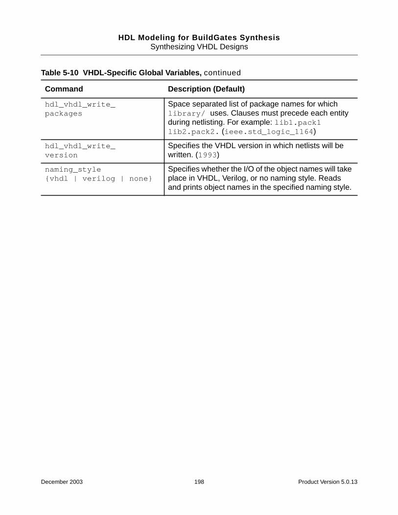
HDL Modeling for BuildGates SynthesisSynthesizing VHDL Designs
hdl_vhdl_write_packages
Space separated list of package names for whichlibrary/ uses. Clauses must precede each entityduring netlisting. For example: lib1.pack1lib2.pack2. (ieee.std_logic_1164)
hdl_vhdl_write_version
Specifies the VHDL version in which netlists will bewritten. (1993)
naming_style{vhdl | verilog | none}
Specifies whether the I/O of the object names will takeplace in VHDL, Verilog, or no naming style. Readsand prints object names in the specified naming style.
Table 5-10 VHDL-Specific Global Variables, continued
Command Description (Default)
December 2003 198 Product Version 5.0.13
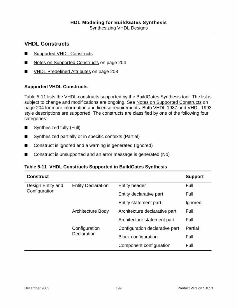
HDL Modeling for BuildGates SynthesisSynthesizing VHDL Designs
VHDL Constructs
■ Supported VHDL Constructs
■ Notes on Supported Constructs on page 204
■ VHDL Predefined Attributes on page 208
Supported VHDL Constructs
Table 5-11 lists the VHDL constructs supported by the BuildGates Synthesis tool. The list issubject to change and modifications are ongoing. See Notes on Supported Constructs onpage 204 for more information and license requirements. Both VHDL 1987 and VHDL 1993style descriptions are supported. The constructs are classified by one of the following fourcategories:
■ Synthesized fully (Full)
■ Synthesized partially or in specific contexts (Partial)
■ Construct is ignored and a warning is generated (Ignored)
■ Construct is unsupported and an error message is generated (No)
Table 5-11 VHDL Constructs Supported in BuildGates Synthesis
Construct Support
Design Entity andConfiguration
Entity Declaration Entity header Full
Entity declarative part Full
Entity statement part Ignored
Architecture Body Architecture declarative part Full
Architecture statement part Full
ConfigurationDeclaration
Configuration declarative part Partial
Block configuration Full
Component configuration Full
December 2003 199 Product Version 5.0.13
HDL Modeling for BuildGates SynthesisSynthesizing VHDL Designs
Subprogram andPackages
SubprogramDeclaration
Full
Subprogram Body Subprogram declarative part Full
Subprogram statement part Full
SubprogramOverloading
Full
Resolution Function Partial
PackageDeclaration
Package declarative part Full
Deferred constants Full
Package Body Full
Types Scalar TypeDefinition
Enumeration type Full
Integer Full
Physical Ignored
Floating Ignored
Composite TypeDefinition
Array Full
Record Full
Access TypeDefinition
Ignored
File Type Definition Ignored
Table 5-11 VHDL Constructs Supported in BuildGates Synthesis, continued
Construct Support
December 2003 200 Product Version 5.0.13
HDL Modeling for BuildGates SynthesisSynthesizing VHDL Designs
Declarations SubprogramDeclaration
Full
Subprogram Body Full
Type Declaration Full
SubtypeDeclaration
Full
Object Declaration Constant Full
Signal Full
Variable Full
Shared variable No
File No
Alias Declaration Full
AttributeDeclaration
Full
ComponentDeclaration
Full
Group TemplateDeclaration
No
Group Declaration No
Specifications AttributeSpecification
Full
ConfigurationSpecification
Full
DisconnectionSpecification
No
Table 5-11 VHDL Constructs Supported in BuildGates Synthesis, continued
Construct Support
December 2003 201 Product Version 5.0.13

HDL Modeling for BuildGates SynthesisSynthesizing VHDL Designs
Expressions Logical Operators and, or, nand, nor, xor, xnor Full
RelationalOperators
=, /=, >, <, >=, <= Full
Shift Operators sll, srl, sra
sla, ror, rol
Full
Partial
ArithmeticOperators
+, -, & Full
Sign Operators +, - Full
MultiplyingOperators
*
mod
/, rem
Full
Full
Full
MiscellaneousOperators
* *
abs
not
Partial
Full
Full
Operands Integer literal Full
Real literal Ignore
Physical literal Ignore
Enumeration literal Full
String literal Full
Bit string literal Full
Null literal No
Aggregates Record aggregates Full
Array aggregates Full
Function calls Qualified expression Full
Type conversion Full
Allocators No
Table 5-11 VHDL Constructs Supported in BuildGates Synthesis, continued
Construct Support
December 2003 202 Product Version 5.0.13
HDL Modeling for BuildGates SynthesisSynthesizing VHDL Designs
SequentialStatements
Wait Sensitivity clause Partial
Condition clause Partial
Timeout clause Ignored
Assertion Ignored
Report Ignored
Signal Assignment Full
VariableAssignment
Full
Procedure Call Full
If Full
Case Full
Loop Unconditional loop No
While loop Partial
For loop Full
Next Full
Exit Full
Return Full
Null Full
ConcurrentStatements
Block Guard No
Block header No
Block declarative part Full
Block statement part Full
Timeout clause Ignored
Table 5-11 VHDL Constructs Supported in BuildGates Synthesis, continued
Construct Support
December 2003 203 Product Version 5.0.13
HDL Modeling for BuildGates SynthesisSynthesizing VHDL Designs
Notes on Supported Constructs
The following sections provide information for the constructs described in Table 5-11.
Design Entities and Configurations
■ Generics and ports in an entity header can be of any allowable synthesizable type in aninterface object (bit, boolean, bit_vector, integer). See Types on page 205 formore information.
■ Generics must have a default value specified, unless the entity has a TEMPLATE attributeset to TRUE. See VHDL Synthesis Directives on page 174 for more information.
■ Declarations in an entity or architecture declarative part must be supported declarations.See Declarations on page 206 for more information.
■ Configuration declarations and configuration specifications are supported with therestriction that only one unique architecture is bound to an entity throughout the design.
ConcurrentStatements, cont.
Process Full
ConcurrentProcedure Call
Full
ConcurrentAssertion
Ignored
Concurrent SignalAssignment
Conditional signal assignment Full
Selected signal assignment Full
ComponentInstantiation
Full
GenerateStatement
If generate Full
For generate Full
Table 5-11 VHDL Constructs Supported in BuildGates Synthesis, continued
Construct Support
December 2003 204 Product Version 5.0.13
HDL Modeling for BuildGates SynthesisSynthesizing VHDL Designs
Subprograms and Packages
■ Impure functions are unsupported.
■ Recursive subprograms are supported.
■ Formal parameters in a subprogram declaration can be of any synthesizable typeallowed for an interface object (for example, bit, boolean, bit_vector, integer).See Types below for more information.
■ Declarations in a subprogram declarative part, package declarative part, or packagebody declarative part must be a supported declaration. See Declarations on page 206for more information.
■ The resolved function defined in package IEEE.STD_LOGIC_1164 is the onlysupported resolution function. User-defined resolution functions can be annotated withthe RESOLUTION attribute to force a WIRED_AND, WIRED_OR, or WIRED_TRI behavior.Refer to VHDL Synthesis Directives on page 174 for further information.
Types
■ Objects (constants, signals, variables) declared with a subtype that is an ignored type orderived from an ignored type are unsupported. For example, floating type definitions areignored but a signal of that floating type is flagged as an error. For example:
type GET_REAL is 2.4 to 3.9; --Ignored type definition
signal S: GET_REAL; --Error!
■ The attribute ENUM_ENCODING is used to override the default mapping between anenumerated type and the corresponding encoding value. Refer to VHDL SynthesisDirectives on page 174 for further information.
■ Array type definitions are supported (see examples below).
subtype BYTE is bit_vector(7 downto 0);
type COLORS is (SAFFRON, WHITE, GREEN, BLUE);
type BIT_2D is array (0 to 255, 0 to 7) of bit;
type ANOTHER_BIT_2D is array (0 to 10) of BYTE;
type BITVECTOR_1D is array (0 to 255) of BYTE;
type INTEGER_1D is array (0 to 255) of integer;
type ENUM_1D is array (0 to 255) of COLOR;
type BOOL_1D is array (COLORS) of boolean;
-- a three dimensional bit
type BIT_3D is array (0 to 10) of BIT_2D;
-- a two dimensional integer
type INTEGER_2D is array (0 TO 10, 0 TO 10) of integer;
December 2003 205 Product Version 5.0.13
HDL Modeling for BuildGates SynthesisSynthesizing VHDL Designs
■ Interface Objects (formal ports of an entity or a component, formal parameters of asubprogram) can be of any supported type.
■ Null ranges are not supported.
Declarations
■ Initial values are supported for variables in a subprogram body.
■ Deferred constants are supported.
■ Signal kinds (bus and register) are unsupported.
■ Mode linkage in interface objects is unsupported.
■ All type declarations can be read in, but only objects of supported types described in thetypes section are allowed to be declared.
■ User-defined attribute declarations and specifications are supported.
Names
■ Selected names that refer to elements of a record are supported.
■ Selected names used as expanded names are supported. An expanded name is usedto denote a declaration from a library, package, or other named construct.
■ The following predefined attributes are supported: base, left, right, high, low,range, reverse_range, length.
■ The following predefined attributes are only supported in the context of clock edgespecifications: event, stable.
■ Expressions in attribute names are unsupported.
■ User defined attribute names are supported.
■ Indexing and slicing of function return values is supported.
Expressions
■ Signed arithmetic is supported.
■ The following operators are only supported in the VHDL 1993 mode: xnor, sll, srl,sla, sra, rol, ror.
December 2003 206 Product Version 5.0.13
HDL Modeling for BuildGates SynthesisSynthesizing VHDL Designs
■ The /, mod, and rem expressions are fully supported of you have the BGX or the PKSlicense. Otherwise, they are supported when both the operands are constants or whenthe right operand is a static power of 2.
■ The ** operator is only supported when both the operands are constants or when theleft operand is a power of 2.
■ Real and physical literals may only exist in after clauses, where they are ignored.
■ The TYPE_CONVERSION directives may be used to tag user-defined functions as havinga type conversion behavior. Refer to VHDL Synthesis Directives on page 174 for furtherinformation.
■ Slices whose ranges cannot be determined statically are not supported.
■ Slices of array objects are supported. Similarly, direct indexing of a bit within an array issupported. For example:
subtype BYTE is bit_vector(3 downto 0);
type MEMTYPE is array (255 downto 0) of BYTE;
variable MEM: MEMTYPE;
variable B1: bit;
…
MEM(3 downto 0):= X; -- supported multi-word slice
B1:= MEM(3)(0); -- supported reference to bit
■ sla operator is implemented as a logical left shift.
■ ror and rol operators are available with Datapath Synthesis of BuildGates Synthesisand Cadence Physically Knowledgeable Synthesis (PKS).
Sequential Statements
■ When an explicit wait statement is used, it must be the first statement of a process. Thecondition clause must represent the clock edge specification. The sensitivity clause, ifany, must only contain the clock signal specified in the condition clause.
■ Multiple wait statements in a process (implicit state machines) are unsupported.
■ Assignments that involve multiple “words” of 2-dimensional (or higher) objects aresupported.
■ The range in a for loop must be statically computable.
■ Delay mechanisms in signal assignments are ignored.
■ Multiple waveforms in signal assignments are unsupported.
December 2003 207 Product Version 5.0.13
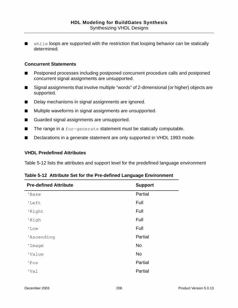
HDL Modeling for BuildGates SynthesisSynthesizing VHDL Designs
■ while loops are supported with the restriction that looping behavior can be staticallydetermined.
Concurrent Statements
■ Postponed processes including postponed concurrent procedure calls and postponedconcurrent signal assignments are unsupported.
■ Signal assignments that involve multiple “words” of 2-dimensional (or higher) objects aresupported.
■ Delay mechanisms in signal assignments are ignored.
■ Multiple waveforms in signal assignments are unsupported.
■ Guarded signal assignments are unsupported.
■ The range in a for-generate statement must be statically computable.
■ Declarations in a generate statement are only supported in VHDL 1993 mode.
VHDL Predefined Attributes
Table 5-12 lists the attributes and support level for the predefined language environment
Table 5-12 Attribute Set for the Pre-defined Language Environment
Pre-defined Attribute Support
‘Base Partial
‘Left Full
‘Right Full
‘High Full
‘Low Full
‘Ascending Partial
‘Image No
‘Value No
‘Pos Partial
‘Val Partial
December 2003 208 Product Version 5.0.13
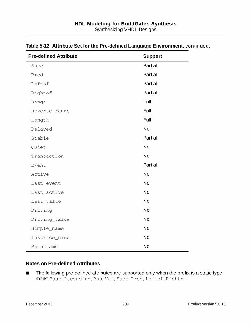
HDL Modeling for BuildGates SynthesisSynthesizing VHDL Designs
Notes on Pre-defined Attributes
■ The following pre-defined attributes are supported only when the prefix is a static typemark: Base, Ascending, Pos, Val, Succ, Pred, Leftof, Rightof
‘Succ Partial
‘Pred Partial
‘Leftof Partial
‘Rightof Partial
‘Range Full
‘Reverse_range Full
‘Length Full
‘Delayed No
‘Stable Partial
‘Quiet No
‘Transaction No
‘Event Partial
‘Active No
‘Last_event No
‘Last_active No
‘Last_value No
‘Driving No
‘Driving_value No
‘Simple_name No
‘Instance_name No
‘Path_name No
Table 5-12 Attribute Set for the Pre-defined Language Environment, continued,
Pre-defined Attribute Support
December 2003 209 Product Version 5.0.13

HDL Modeling for BuildGates SynthesisSynthesizing VHDL Designs
■ The following pre-defined attributes are supported only in the context of clock edgespecifications:
❑ Event, Stable
■ Expressions in attribute names are not supported.
Troubleshooting
Additional troubleshooting information can be found in the latest version of Known Problemsand Solutions for BuildGates Synthesis and Cadence PKS that accompanied yourrelease.
■ VHDL Netlist from write_vhdl Missing Generic Delay Parameters on page 211
■ Cannot Infer a Bus Keeper Element Using a BLOCK/GUARDED Statement on page 211
■ Extra Generic Logic Added to VHDL Netlist with Undriven Nets on page 211
■ Undriven Ports and Nets Left After Optimization on page 211
■ Error When Using IEEE Standard Logic Packages in BuildGates on page 212
■ Unconnected Flip Flops in the Final Netlist on page 212
■ Setting Finite State Machine Compile Directives for a VHDL Finite State on page 213
■ Error During do_build_generic if Design Architecture is not Specified on page 214
■ Unconditional Loops are not Supported if There is More than One Clock Edge onpage 214
■ Error on the Condition Clause of a wait Using read_vhdl on page 215
■ VHDL LOOP Construct Runs Out of Memory on page 216
■ Undeclared Identifier Error Message in VHDL Structural Netlists on page 217
■ Locally Static Expressions in VHDL87 LRM and VHDL93 LRM on page 218
■ VHDL93 LRM Definition of a Locally Static Expression on page 218
■ Using the \ Character in VHDL on page 218
■ Passing Generic Values from the Command Line on page 219
■ Writing One-Bit Busses on page 219
December 2003 210 Product Version 5.0.13
HDL Modeling for BuildGates SynthesisSynthesizing VHDL Designs
VHDL Netlist from write_vhdl Missing Generic Delay Parameters
Currently, BuildGates does not write out the generic delay parameters in a VHDL netlist.Commonly, the ASIC vendor would have to provide a technology package with all thecomponent declarations. Link this package in the VHDL code and instruct BuildGates not towrite out the technology components in the netlist with the following command:
set_global hdl_vhdl_write_components false
Cannot Infer a Bus Keeper Element Using a BLOCK/GUARDED Statement
There is no special VHDL code to infer a bus keeper. It depends on the behavior of the buskeeper. BLOCK/GUARDED statements are not supported in BuildGates.
Extra Generic Logic Added to VHDL Netlist with Undriven Nets
When reading a VHDL mapped netlist containing undriven nets, do_build_generic willadd generic components ATL_TRI or ATL_DC if the global variablehdl_undriven_net_value is set to Z or X respectively. These inadvertently added genericcomponents cause the tool to fail when a transform command, which requires a mappednetlist, is called, for example, do_xform_timing_correction.
The hdl_undriven_net_value variable assumes a value for an undriven net to be usedduring constant propagation. Constant propagation is performed during the genericoptimization step. If this step is skipped, then the do_xform_constant_propagationneeds to be run prior to timing optimization. Use the following global to tell the tool not to addany logic to an undriven net:
set_global hdl_undriven_net_value none.
Undriven Ports and Nets Left After Optimization
Use the following command before do_optimize. For example:
do_dissolve_hierarchy [find -module A}
This will eliminate the undriven ports.
December 2003 211 Product Version 5.0.13
HDL Modeling for BuildGates SynthesisSynthesizing VHDL Designs
Error When Using IEEE Standard Logic Packages in BuildGates
If you have used other synthesis tools such as Synergy or Design Compiler, several“environments” may need to be set up to use specific IEEE packages. If the IEEE packageyou used is not available in BuildGates 5.0, an error message similar to the one below will beissued:
==> ERROR: No such primary unit std_logic_unsigned in library IEEE (Filefoo.vhdl, Line3)<VHDLPT-703>.
Info: +: library “IEEE” mapes to “ieee”
+: library “ieee” maps to “/ambit/prod3/v4.0-s005.20010117.1900/
release/BuildGates/version/lib/tools/vhdl/1993/ieee_ambit”
<VHDLPT-525>.
➤ Use the following command to access the different IEEE std_logic packages:
set_global hdl_vhdl_environment {standard | synopsys | synergy | common}
The four predefined VHDL environments that are available are described in section, Settingthe Globals for Synthesizing VHDL Designs on page 144.
Unconnected Flip Flops in the Final Netlist
➤ If you have extra unconnected registers in the netlist, set the globalhdl_preserve_unused_registers to false.
For example, if declared VHDL variables in the clocked process are used as inputs to othersignals within the same process, BuildGates generates unconnected flip-flops for thosevariables, then preserves the unconnected flip-flops during optimization if this global is set totrue.
December 2003 212 Product Version 5.0.13
HDL Modeling for BuildGates SynthesisSynthesizing VHDL Designs
Setting Finite State Machine Compile Directives for a VHDL Finite State
FSM optimization is controlled by using the attributes defined in the packageambit.attributes. At the top of your VHDL source file, add the lines:
LIBRARY ambit;
USE ambit.attributes.all;
The source code for this package can be found at:
<install_dir>/BuildGates/version/lib/tools/vhdl/1993/ambit/attributes.vhd
The FSM related attributes are the following:
attribute STATE_VECTOR : boolean;
attribute MINIMIZE : boolean
attribute REACHABLE : boolean;
attribute ENCODING : string;
attribute PRESERVE : string;
attribute INITIAL : string;
Using them in your VHDL source code is as simple as adding some additional declarationswhere you define your state vector. In the following example, the vector is curr_state:
TYPE statetype IS (idle,load, check, wait, finish);
SIGNAL curr_state : statetype;
SIGNAL next_state : statetype;
attribute STATE_VECTOR of curr_state:signal is true;
attribute ENCODING of curr_state:signal is "one_hot";
attribute MINIMIZE of curr_state:signal is TRUE;
attribute REACHABLE of curr_state:signal is TRUE;
This will allow BuildGates Synthesis to see the FSM compiler directives.
December 2003 213 Product Version 5.0.13

HDL Modeling for BuildGates SynthesisSynthesizing VHDL Designs
Error During do_build_generic if Design Architecture is not Specified
Make sure when you read in an entity named, for example, ‘foo’ using read_vhdl, thatyou read in the associated architecture, or BuildGates will treat this as an error duringdo_buld_generic and abort the elaboration.
Note: If both the entity and the architecture are missing, BuildGates just prints a warning andtreats the missing design as a black box.
However, if you read in the architecture, and you receive an error, it is possible that a previousentity or package (on which foo is dependent) was read for a second time into BuildGates.Look for an unintended design dependency. You can use UNIX scripts to grep out entity,architecture, and package names from your source code and verify that they are unique fromeach other. Sub designs developed from the same code may actually be different. Forexample, a synchronous and asynchronous UART, or two similar memory controllers mayhave some sub design names in common.
Unconditional Loops are not Supported if There is More than One ClockEdge
The read_vhdl command does not support the following example because it contains morethan one clock edge in a process:
entity e is
port (q : out bit; d : in bit_vector (7 downto 0));
end
architecture a of e is
begin
process (d)
variable x : integer;
variable tmp : bit;
begin
x := 7;
tmp := ‘0’;
loop
tmp := tmp xor d(x);
exit when x = 0;
x := x - 1;
end loop;
q <= tmp;
end process;
end
December 2003 214 Product Version 5.0.13
HDL Modeling for BuildGates SynthesisSynthesizing VHDL Designs
Error on the Condition Clause of a wait Using read_vhdl
For example, the following RTL coding style of synchronous enable or reset:
WAIT UNTIL ck’EVENT AND ck=’1’ AND (nd=’1’ OR shifting_data);
which uses “wait on the clock edge” AND “a qualifier”, results in errors during the parsingstage of reading the VHDL code (read_vhdl).
Since the data is being qualified with nd and shifting_data this renders it as asynchronous enable. Therefore, model the circuit in one of the following two ways:
■ Using a sensitivity list in the process statement:
library ieee;
use ieee.std_logic_1164.all;
use ieee.std_logic_arith.all;
entity qful is
port (clk : in std_ulogic;
nd : in std_ulogic;
shifting_data : in boolean;
latch3_n : out std_ulogic
);
end qful;
architecture rtl of qful is
begin
latch_proc: process (clk)
begin
if (clk = ’1’) and (clk’event) then
if (nd = ’1’) or shifting_data then
latch3_n <= ’1’;
end if;
end if;
end process;
end rtl;
December 2003 215 Product Version 5.0.13
HDL Modeling for BuildGates SynthesisSynthesizing VHDL Designs
■ Using the wait statement:
library ieee;
use ieee.std_logic_1164.all;
use ieee.std_logic_arith.all;
entity qful is
port (clk : in std_ulogic;
nd : in std_ulogic;
shifting_data : in boolean;
latch3_n : out std_ulogic
);
end qful;
architecture rtl1 of qful is
begin
latch_proc: process
begin
wait until clk = ’1’ and clk’event;
if (nd = ’1’ or shifting_data) then
latch3_n <= ’1’;
end if;
end process;
end rtl1;
VHDL LOOP Construct Runs Out of Memory
The contents of the loop, times the number of iterations, determines how much memory isbeing allocated. There is a limit on the number of loop iterations specified by the globalvariable: hdl_max_loop_limit. For example,
wrapper : PROCESS (reg_value, inbits) -- RUNS OUT OF MEMORY!
BEGIN
FOR i IN NUMBITS-1 DOWNTO 0 LOOP
outbits(i) <= reg_value(i) AND inbits(i);
END LOOP;
END PROCESS;
outbits <= reg_value AND inbits; -- WORKS OK!
Break the LOOP into smaller (fewer iteration) loops by nesting them or by separatingfunctions. Or, in some cases, you may be able to eliminate the LOOP altogether by operatingon vectors instead of on bits.
December 2003 216 Product Version 5.0.13
HDL Modeling for BuildGates SynthesisSynthesizing VHDL Designs
Undeclared Identifier Error Message in VHDL Structural Netlists
Although .alf has the component definitions, BuildGates requires that the componentdefinitions of the cells be included in the architecture. This can be done by:
1. Using a use clause to access the component declarations from a package.
library xyz;
use xyz.libname.all
2. Manually inserting the component declarations in the netlist (architecture).
December 2003 217 Product Version 5.0.13

HDL Modeling for BuildGates SynthesisSynthesizing VHDL Designs
Locally Static Expressions in VHDL87 LRM and VHDL93 LRM
In the following declaration:
type GRA_T is array (0 to (2**RA’length)-1) of std_logic_vector(DIN’length -1)
where RA is:
signal RA : in std_logic_vector(3 downto 0);
the range expression 0 to (2**RA’length)-1) is not locally static according to the VHDL87 LRM but it is locally static according to the VHDL93 LRM.
In the VHDL87 LRM, “A predefined attribute of a locally static subtype that is a value” is alocally static expression. In this case, the predefined attribute (length) is on a signal objectthat is of a locally static type, and not on a locally static subtype.
Example 5-1 Using a VHDL87 LRM Range Expression that is Locally Staticsubtype xyz is std_logic_vector(3 downto 0);
type GRA_T is array (0 to (2**xyz’length)-1) of std_logic_vector(DIN’length -1downto 0);
In this example, the range expression 0 to(2**xyz’length)-1 is a locally staticexpression because the predefined attribute ‘LENGTH is on a locally static subtype xyz andthe expression 2 ** xyz’length -1 is a value (value = 2 **3 -1 =7).
VHDL93 LRM Definition of a Locally Static Expression
“A predefined attribute that is a value, other than the predefined attribute PATH_NAME, andwhose prefix is either a locally static subtype or is an object name that is of a locally staticsubtype.” In the VHDL93 LRM, objects of locally static subtypes were also included in thecontext. This causes RA’LENGTH to qualify as a locally static expression, causing the Rangeand the Type GRA_T to be locally static as well.
Using the \ Character in VHDL
The \ character in VHDL lets you specify characters that are not legal in VHDL. If you wantto include characters in a name which are illegal in VHDL, add a \ character before and afterthe name, and add space after the name.
December 2003 218 Product Version 5.0.13
HDL Modeling for BuildGates SynthesisSynthesizing VHDL Designs
Passing Generic Values from the Command Line
➤ To pass VHDL generics from the command line, enter the followingdo_build_generic command arguments. In this way, generic designs can beelaborated directly.
do_build_generic -design FOO -generics { {name1 value1} {name2 value2} ..}
If the -design option is not used, then the default top-level module is built. The generics arespecified as a Tcl list of name and value pairs. The options -generic and -parameterscan be used interchangeably. If fewer generics are specified than exist in the design, then thedefault values of the missing generics will be used in building the design. If more generics arespecified than exist in the design, then the extra generics are ignored.
➤ To synthesize the design ADD with the generic value L=0 and R=7, enter the followingcommand:
do_build_generic -design ADD -generics {{L 0} {R 7}}
➤ To synthesize all bit widths for the adder ADD from 1 through 16, use:
foreach i {0 1 2 3 4 5 6 7 8 9 10 11 12 13 14 15} {
eval do_build_generic -generics “{{L 0} {R[expr $i]}}”
}
Writing One-Bit Busses
One bit busses are written out in BuildGates Synthesis in the following manner to keep thedatabase and the netlist consistent:
wire [0:0]xsig
To write a 1-bit bus as a simple signal, such as wire xsig, use one of the followingworkarounds:
1. In the database, modify the port type to a bit type using Tcl commands.
2. Do not write signals like the following in the RTL code:
out std_logic_vector (0 downto 0)
Use a single-bit type such as std_logic or std_ulogic instead by setting thefollowing global:
set_global hdl_vhdl_write_bit_type { std_logic | std_ulogic }
December 2003 219 Product Version 5.0.13
HDL Modeling for BuildGates SynthesisSynthesizing VHDL Designs
December 2003 220 Product Version 5.0.13

HDL Modeling for BuildGates Synthesis
6Optimizing and Structuring Finite StateMachines
This chapter describes how to model a Finite State Machine (FSM), and how to synthesizeand optimize a FSM using BuildGates® Synthesis.
■ Overview on page 222
■ Tasks on page 225
■ Additional Information on page 228
■ Troubleshooting on page 243
December 2003 221 Product Version 5.0.13

HDL Modeling for BuildGates SynthesisOptimizing and Structuring Finite State Machines
Overview
Using an FSM to describe internal states of the design lets BuildGates Synthesis determinean encoding of those states, which results in a netlist that best meets the specified timingconstraints. This chapter provides guidelines for specifying FSMs in the RTL design, viewingthe state transition table generated by BuildGates, performing various FSM optimizations,and verifying the synthesized netlist:
Figure 6-1 shows the general structure of a Finite State Machine (FSM) that consists of twoblocks of combinational logic, -next state logic- and -output logic-, and a set of flip-flops, -state memory-, clocked by a single clock signal. The -current state- of theFSM is the value stored in the state memory flip-flops.
Figure 6-1 State Machine Structure—Two Case Statements
Specify a state machine as shown in Example 6-1, using case statements or if-then-else statements for the next state and output logic, and using a clocked process (VHDL) oralways block (Verilog) for the state memory.
➤ Identify the state memory by using the state_vector directive for Verilog designs:
// cadence state_vector state
or by using the state_vector attribute for VHDL designs:
attribute STATE_VECTOR of state : signal is true;
clocks
OutputNext outputs
StateLogic
StateMemory Logic
inputs
current state
nextstate
December 2003 222 Product Version 5.0.13
HDL Modeling for BuildGates SynthesisOptimizing and Structuring Finite State Machines
Example 6-1 Modeling a State Machinemodule fsm1 (clk,reset,start,go,z);
input clk,reset,start,go
output z;
parameter [1:0]
RED = 2’b00
BLUE = 2’b00
YELLOW = 2’b01
GREEN = 2’b10
reg [1:0] state;
reg [1:0] next_state;
reg z;
// cadence state_vector state
always @(posedge clk or posedge reset)
begin
if (reset)
state <= RED;
else
state <= next_state;
end
always @(state or start or go)
begin
z = 1’b0;
case (state)
RED : begin
if (start)
next_state = BLUE;
else
next_state = RED;
end
BLUE : next_state = YELLOW;
YELLOW : next_state = GREEN;
GREEN : begin
z = go;
if (start)
December 2003 223 Product Version 5.0.13
HDL Modeling for BuildGates SynthesisOptimizing and Structuring Finite State Machines
next_state = RED;
else
next_state = GREEN;
end
endcase
end
endmodule
➤ After reading in the design data, synthesize the FSM during the "Build Generic Design"phase shown in Fig. 6-2 by issuing the following command:
do_build_generic -extract_fsm
Important
Both the -extract_fsm switch and the state_vector directive are required forBuildGates to apply the specialized FSM extraction and optimization techniques. IfFSM synthesis does not occur, BuildGates will perform normal RTL synthesis asdescribed in Chapter 3, “Synthesizing Verilog Designs,” and Chapter 5,“Synthesizing VHDL Designs.”
➤ View the report of the synthesized FSM, including the generated state transition tableand state encoding, by entering the following command at the shell prompt:
report_fsm -state_table -encoding
Figure 6-2 Rtl Synthesis Flow - FSM
Read Design Data
ReportWrite Netlist
Build Generic Design
Optimize Design
December 2003 224 Product Version 5.0.13
HDL Modeling for BuildGates SynthesisOptimizing and Structuring Finite State Machines
Tasks
The standard tasks you complete to synthesize a finite state machine are described in thefollowing sections.
■ Model FSM on page 225
■ Synthesize FSM on page 225
Model FSM
After reading the design data into the BuildGates Synthesis software, extract and view thestate transition table for the FSM.
Extracting the State Transition Table for the FSM
➤ Enter the following command in the shell prompt:
do_build_generic -extract_fsm
Note: BuildGates Synthesis only performs FSM optimization when the -extract_fsmoption is specified.
Viewing the State Transition Table for the FSM
After you extract the state transition table for the FSM, you can view it. The state transitiontable contains information about equivalent states, initial states, and state encodings.
➤ Enter the following command in the shell prompt:
report_fsm -state
Synthesize FSM
The following list of FSM optimizations are listed by order of importance and the impact theyhave on the quality of results (QoR). Use Cadence Synthesis pragmas to perform these FSMoptimizations.
■ Setting State Vector Encoding Styles for Better Area and Timing on page 226
■ Minimizing FSM State if There are Two or More Equivalent States on page 227
■ Checking Terminal State on the Extracted FSM on page 227
December 2003 225 Product Version 5.0.13
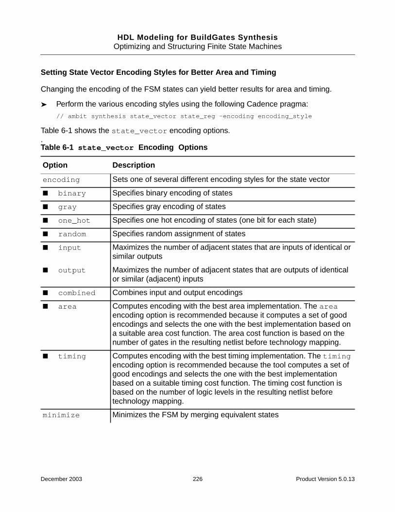
HDL Modeling for BuildGates SynthesisOptimizing and Structuring Finite State Machines
Setting State Vector Encoding Styles for Better Area and Timing
Changing the encoding of the FSM states can yield better results for area and timing.
➤ Perform the various encoding styles using the following Cadence pragma:
// ambit synthesis state_vector state_reg -encoding encoding_style
Table 6-1 shows the state_vector encoding options..Table 6-1 state_vector Encoding Options
Option Description
encoding Sets one of several different encoding styles for the state vector
■ binary Specifies binary encoding of states
■ gray Specifies gray encoding of states
■ one_hot Specifies one hot encoding of states (one bit for each state)
■ random Specifies random assignment of states
■ input Maximizes the number of adjacent states that are inputs of identical orsimilar outputs
■ output Maximizes the number of adjacent states that are outputs of identicalor similar (adjacent) inputs
■ combined Combines input and output encodings
■ area Computes encoding with the best area implementation. The areaencoding option is recommended because it computes a set of goodencodings and selects the one with the best implementation based ona suitable area cost function. The area cost function is based on thenumber of gates in the resulting netlist before technology mapping.
■ timing Computes encoding with the best timing implementation. The timingencoding option is recommended because the tool computes a set ofgood encodings and selects the one with the best implementationbased on a suitable timing cost function. The timing cost function isbased on the number of logic levels in the resulting netlist beforetechnology mapping.
minimize Minimizes the FSM by merging equivalent states
December 2003 226 Product Version 5.0.13

HDL Modeling for BuildGates SynthesisOptimizing and Structuring Finite State Machines
Minimizing FSM State if There are Two or More Equivalent States
State minimization optimization tells BuildGates Synthesis to minimize and validate the FSM.Each state of an FSM typically corresponds to a unique behavior. In some cases, however,two or more equivalent states, having identical I/O behavior, can occur in a state machine. Ifequivalent states are found in the design, it may mean that the design has a bug. If you areconfident that the design does not have any equivalent states, then ignore this option toreduce run time.
➤ Perform state minimization using the following Cadence pragma:
//ambit synthesis state_vector state_reg -minimize
Checking Terminal State on the Extracted FSM
A terminal state check is always performed on the extracted FSM. A terminal state is a stateof the FSM from which there are no outputs. A well designed state machine should neverhave a terminal state. If such a state is found in the FSM, it is included in the FSM report (seeViewing the State Transition Table for the FSM on page 210).
reachable Removes all unreachable and invalid states from the state machine,including the default case which represents the invalid states of theFSM to be treated as don’t cares. This option reduces the run timeas the BuildGates Synthesis software handles the actions from invalidstates (represented by the default case). For a sparsely encodedmachine, the number of unreachable (invalid) states can be large,leading to larger run times. This option is recommended for shorter runtimes and will improve optimization.
preserve_state Specifies the states to be preserved and prevents those states frombeing removed by the minimize or reachable options.
initial_states Specifies the states to be set as the initial states of the FSM.
Table 6-1 state_vector Encoding Options, continued
Option Description
December 2003 227 Product Version 5.0.13

HDL Modeling for BuildGates SynthesisOptimizing and Structuring Finite State Machines
Additional Information
■ state_vector Directive on page 228
■ FSM Coding Styles on page 230
■ FSM Verification on page 237
state_vector Directive
➤ Use the state_vector synthesis directive to specify the state vector and options forFSM encoding and optimization. The following directive is for Verilog:
// ambit synthesis state_vector sig state_vector_flag
where sig is the name of the signal representing the state vector.
When a FSM is described, information relating to the encoding and optimization of the stateassignments is included in the source as either comments or attributes on the state signal orvariable. See Setting State Vector Encoding Styles for Better Area and Timing on page 226for more information about state_vector syntax and state_vector encoding options.
The state_vector_flag is defined using one or more of the following options as definedin Table 6-1:
■ encoding [binary|gray|one_hot|random|input|output|combined|area|timing]
■ minimize
■ reachable
■ preserve_state
■ initial_state
Example 6-2 shows how to use attributes to specify the VHDL state_vector directive.
December 2003 228 Product Version 5.0.13

HDL Modeling for BuildGates SynthesisOptimizing and Structuring Finite State Machines
Example 6-2 Using the VHDL state_vector Directivelibrary ieee, ambit;
use ieee.std_logic_1164.all;
use ambit.attributes.all;
entity fsm is
port(
clk, rst : in std_logic;
data : out std_logic_vector(1 downto 0)
);
end fsm;
architecture rtl of fsm is
type COLOR is (red, blue, green, yellow);
signal STATE, NEXT_STATE : COLOR;
attribute STATE_VECTOR of STATE : signal is true;
attribute PRESERVE of STATE : signal is "red, blue";
attribute INITIAL of STATE : signal is "red";
attribute REACHABLE of STATE: signal is true;
attribute MINIMIZE of STATE : signal is true;
begin
state_p: process(clk, rst)
begin
if (rst = ’1’) then
STATE <= red;
elsif (rising_edge(clk)) then
STATE <= NEXT_STATE;
end if;
end process state_p;
next_state_p: process(state)
begin
case STATE is
when red =>
data <= "01";
December 2003 229 Product Version 5.0.13
HDL Modeling for BuildGates SynthesisOptimizing and Structuring Finite State Machines
NEXT_STATE <= blue;
when blue =>
data <= "10";
NEXT_STATE <= green;
when green =>
data <= "11";
NEXT_STATE <= red;
when yellow =>
data <= "00";
NEXT_STATE <= red;
end case;
end process next_state_p;
end rtl;
FSM Coding Styles
The following coding styles are recommended to improve the quality of implementation andoptimization on an FSM.
■ Following Coding Style Rules on page 231
■ Using the -reachable Option on page 233
■ Avoiding a Simulation Mismatch on page 233
■ Setting the State and Output Values to Don’t Care Values on page 233
■ Using a Specific Valid State for Outputs on page 233
■ Using a Compact Coding Style on page 234
■ Using a Detailed Coding Style on page 235
■ Specifying an Output Completely on page 235
December 2003 230 Product Version 5.0.13

HDL Modeling for BuildGates SynthesisOptimizing and Structuring Finite State Machines
Following Coding Style Rules
When creating FSMs in BuildGates Synthesis, follow these coding style rules:
■ Code one FSM per module in Verilog or one per entity in VHDL.
■ Keep extraneous logic in the FSM to a minimum—Remove all unused inputs and outputsand any logic that does not affect or depend on the FSM and associated logic.
■ Code the design so that the FSM can be reset to a desired state—The behavior of theFSM is valid only after the reset has taken place. If the first operating cycle of the FSMproduces output values that are important, or if these output values can only be initializedby a default assignment (which may be deleted during optimization with the-reachable option), set the outputs of the FSM to desired values in the reset block.
Example 6-3 shows the default value of out as 00. If the -reachable flag is set, the defaultcase is optimized and out assumes the value 2’bxx (unknown).
December 2003 231 Product Version 5.0.13
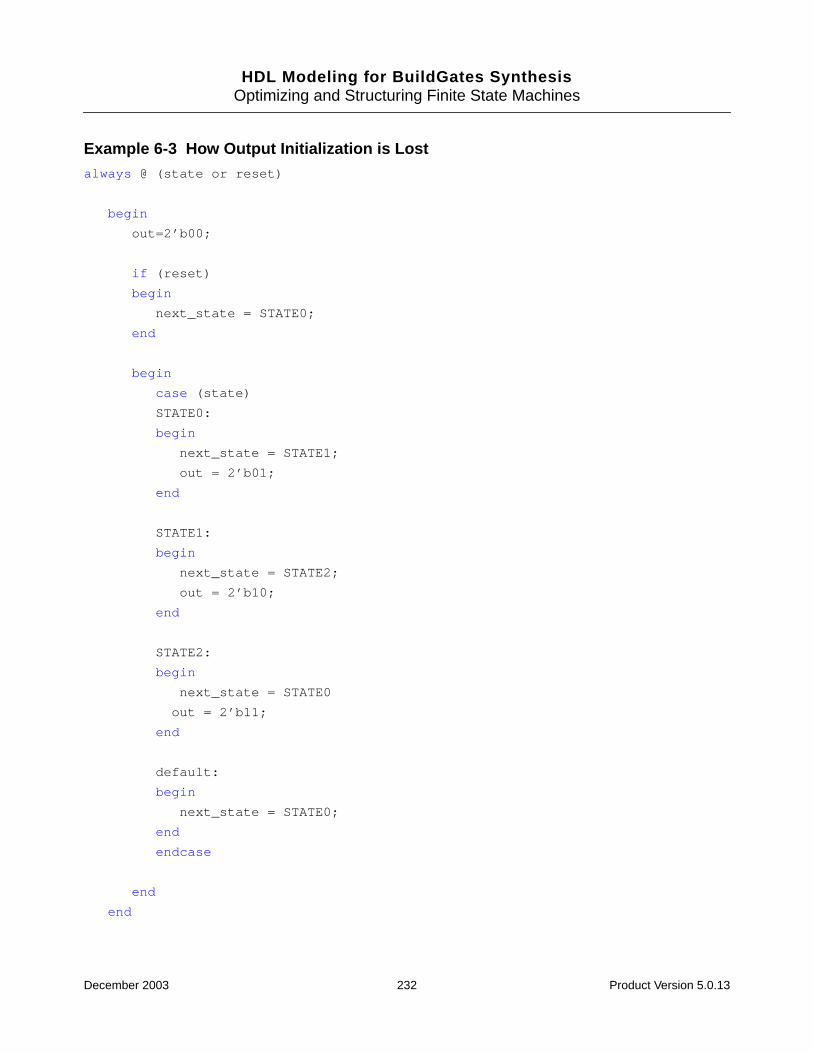
HDL Modeling for BuildGates SynthesisOptimizing and Structuring Finite State Machines
Example 6-3 How Output Initialization is Lostalways @ (state or reset)
begin
out=2’b00;
if (reset)
begin
next_state = STATE0;
end
begin
case (state)
STATE0:
begin
next_state = STATE1;
out = 2’b01;
end
STATE1:
begin
next_state = STATE2;
out = 2’b10;
end
STATE2:
begin
next_state = STATE0
out = 2’b11;
end
default:
begin
next_state = STATE0;
end
endcase
end
end
December 2003 232 Product Version 5.0.13

HDL Modeling for BuildGates SynthesisOptimizing and Structuring Finite State Machines
Using the -reachable Option
➤ To remove the default value of out during optimization, use the following Cadencepragma:
//ambit synthesis state_vector state_reg -reachable
When the simulation begins, the value of out is always 2’bxx.
Note: The simulator interprets the default value as 2’b00 in the RTL. Use the -reachableswitch for large, sparse state vectors.
Avoiding a Simulation Mismatch
To avoid a simulation mismatch, change the reset block as follows:
if (reset) begin
next_state = STATE0;
out = 2b’00;
end
Setting the State and Output Values to Don’t Care Values
Include as much don’t care information as possible in the design. If the transitions from theinvalid states (represented by the default case) are unimportant, then set the state and outputvalues to don’t care values.
default: next_state <= 4’bxxxx;
out1 <= 2’bxx;
Using this method adds flexibility when optimizing the netlist and all invalid (unreachable)states of the FSM can be treated as don’t cares. Use the -reachable option (see Usingthe -reachable Option) with this method.
Using a Specific Valid State for Outputs
If design methodology constraints prohibit the use of the previous method, use a specific validstate, such as the reset state of the FSM or any other valid state and a constant output valuefor outputs. Assign output values explicitly, whenever possible.
default: next_state <= 4’b0000;//reset state of the machine
out1 <= 2’b01;
Important
The following coding style for the default case is not recommended:
December 2003 233 Product Version 5.0.13
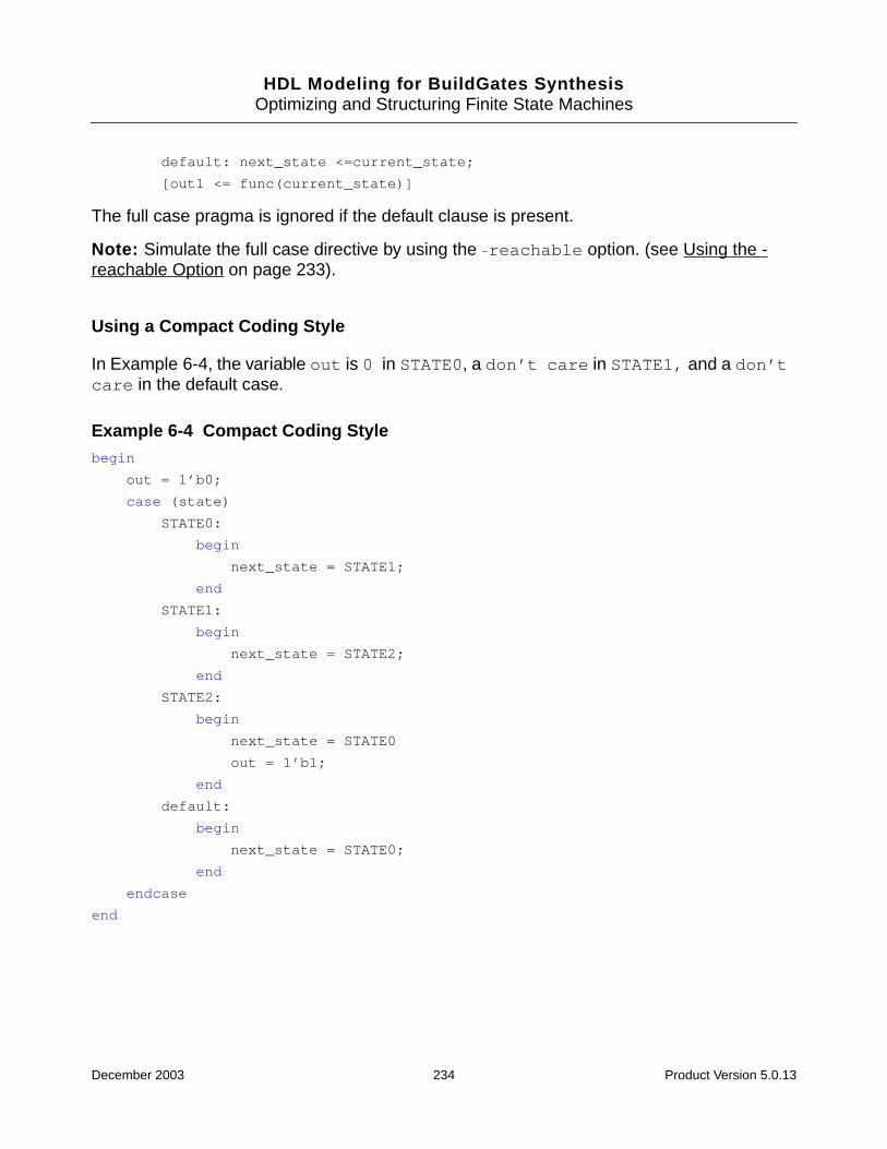
HDL Modeling for BuildGates SynthesisOptimizing and Structuring Finite State Machines
default: next_state <=current_state;
[out1 <= func(current_state)]
The full case pragma is ignored if the default clause is present.
Note: Simulate the full case directive by using the -reachable option. (see Using the -reachable Option on page 233).
Using a Compact Coding Style
In Example 6-4, the variable out is 0 in STATE0, a don’t care in STATE1, and a don’tcare in the default case.
Example 6-4 Compact Coding Stylebegin
out = 1’b0;
case (state)
STATE0:
begin
next_state = STATE1;
end
STATE1:
begin
next_state = STATE2;
end
STATE2:
begin
next_state = STATE0
out = 1’b1;
end
default:
begin
next_state = STATE0;
end
endcase
end
December 2003 234 Product Version 5.0.13
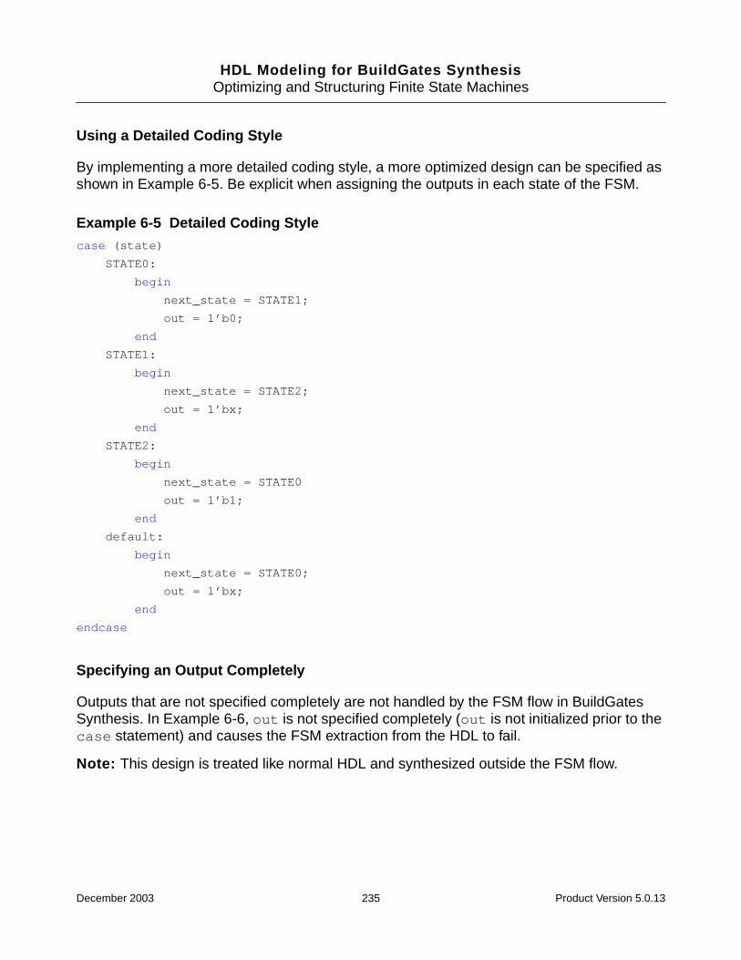
HDL Modeling for BuildGates SynthesisOptimizing and Structuring Finite State Machines
Using a Detailed Coding Style
By implementing a more detailed coding style, a more optimized design can be specified asshown in Example 6-5. Be explicit when assigning the outputs in each state of the FSM.
Example 6-5 Detailed Coding Stylecase (state)
STATE0:
begin
next_state = STATE1;
out = 1’b0;
end
STATE1:
begin
next_state = STATE2;
out = 1’bx;
end
STATE2:
begin
next_state = STATE0
out = 1’b1;
end
default:
begin
next_state = STATE0;
out = 1’bx;
end
endcase
Specifying an Output Completely
Outputs that are not specified completely are not handled by the FSM flow in BuildGatesSynthesis. In Example 6-6, out is not specified completely (out is not initialized prior to thecase statement) and causes the FSM extraction from the HDL to fail.
Note: This design is treated like normal HDL and synthesized outside the FSM flow.
December 2003 235 Product Version 5.0.13
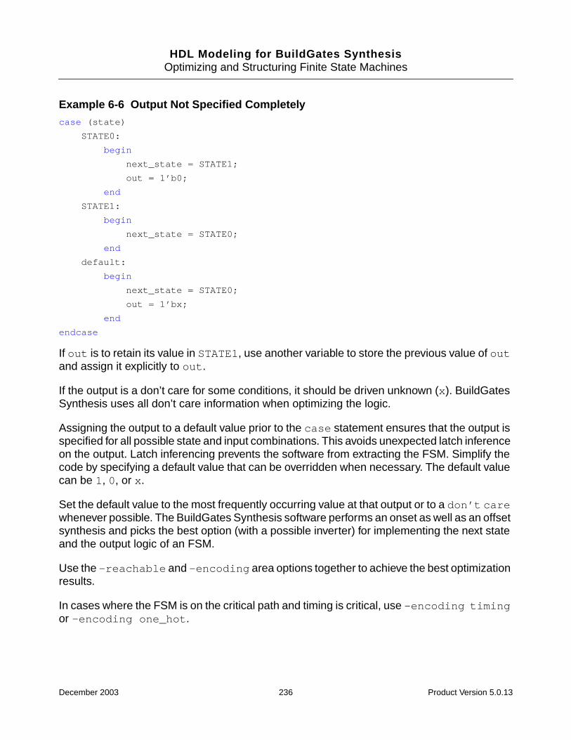
HDL Modeling for BuildGates SynthesisOptimizing and Structuring Finite State Machines
Example 6-6 Output Not Specified Completelycase (state)
STATE0:
begin
next_state = STATE1;
out = 1’b0;
end
STATE1:
begin
next_state = STATE0;
end
default:
begin
next_state = STATE0;
out = 1’bx;
end
endcase
If out is to retain its value in STATE1, use another variable to store the previous value of outand assign it explicitly to out.
If the output is a don’t care for some conditions, it should be driven unknown (x). BuildGatesSynthesis uses all don’t care information when optimizing the logic.
Assigning the output to a default value prior to the case statement ensures that the output isspecified for all possible state and input combinations. This avoids unexpected latch inferenceon the output. Latch inferencing prevents the software from extracting the FSM. Simplify thecode by specifying a default value that can be overridden when necessary. The default valuecan be 1, 0, or x.
Set the default value to the most frequently occurring value at that output or to a don’t carewhenever possible. The BuildGates Synthesis software performs an onset as well as an offsetsynthesis and picks the best option (with a possible inverter) for implementing the next stateand the output logic of an FSM.
Use the -reachable and -encoding area options together to achieve the best optimizationresults.
In cases where the FSM is on the critical path and timing is critical, use -encoding timingor -encoding one_hot.
December 2003 236 Product Version 5.0.13
HDL Modeling for BuildGates SynthesisOptimizing and Structuring Finite State Machines
FSM Verification
■ Avoid Using Sequential Optimizations on page 237
■ Code the Default Clause with a Restricted Structure on page 237
■ Use Only the -reachable Option for Sequential Optimization on page 238
■ View the Valid States on page 238
■ Unreachable or Unspecified States in the FSM on page 238
■ Do Not Specify Any Sequential Optimizations with the State Vector Pragma in the HDLof the FSM on page 238
■ Using a Simulator to Verify the Synthesized FSM on page 239
■ Avoiding Mismatches Between the RTL of the FSM and its Synthesized Netlist onpage 241
■ Checking whether the Extracted FSM is Fault-Tolerant on page 242
■ Verplex Conformal Logical Equivalency Checker on page 242
Avoid Using Sequential Optimizations
To avoid using any sequential optimizations, the default clause of the case statement thatdefines the state machine must have a restricted structure.
The default clause represents the action taken by the state machine upon reaching an invalidstate. Use a reset signal to set the FSM to a reset state so that the machine can startoperating. Using this approach, the FSM never enters the default case (invalid states).
Note: Constraints should not be imposed on invalid states.
Code the Default Clause with a Restricted Structure
To code the default clause of the case statement that defines the state machine with arestricted structure, model your code as follows:
default: next_state <= 4’bxxxx;
out <= 2’bxx;
This approach provides the BuildGates Synthesis software with added flexibility whenoptimizing the netlist, and all invalid (unreachable) states of the FSM are treated as don’tcares. You also avoid generating any false counter examples (where the state vectorcomponent is invalid).
December 2003 237 Product Version 5.0.13
HDL Modeling for BuildGates SynthesisOptimizing and Structuring Finite State Machines
Use Only the -reachable Option for Sequential Optimization
Examine the output from the equivalence checker, which is essentially a value assignment(difference vector), in terms of the inputs and latches of the design that violate the expectedoutcome.
// ambit synthesis state_vector state -reachable
View the Valid States
➤ Enter the following command in the shell prompt:
report_fsm -state
If the state register component of the difference vectors (generated as counter examples)belongs to the invalid or unreachable states, then it is a false alarm and can be ignored.
Unreachable or Unspecified States in the FSM
All unreachable or unspecified states of the FSM are reported by the report_fsmcommand.
The OTHERS state in the state transition table represents the set of unreachable orunspecified states of the FSM. For example, for one-hot encoding, OTHERS is the set of allstates with more than one 1.
Unreachable states specified in the RTL are not included in the OTHERS set. For example, ifthe RTL has:
case (curr_state)
STATE0 :
...
but there is no transition to state STATE0 in the RTL, STATE0 is reported as an unreachablestate.
Do Not Specify Any Sequential Optimizations with the State Vector Pragma in the HDLof the FSM
This approach does not specify any sequential optimizations with the state vector pragma inthe HDL of the FSM (sequential optimizations such as removing unreachable states byspecifying them as don’t cares, setting state vector encoding styles for better area andtiming, and performing FSM state minimization if there are two or more equivalent states).There is a little room for optimization using the do_build_generic command with the-extract_fsm option.
December 2003 238 Product Version 5.0.13
HDL Modeling for BuildGates SynthesisOptimizing and Structuring Finite State Machines
Using a Simulator to Verify the Synthesized FSM
Most design environments have the simulation environment set up to assert the reset signal,which initializes a subset of the memory elements in the full design. The FSM state registeris also reset to the desired start state by such a reset line. The importance of being able toreset the state register is emphasized in the state_vector Directive on page 228.
After the simulation begins, the FSM enters the start state and always operates in the set ofvalid states (if the FSM is well designed). As the simulation environment examines the inputand output behavior of the FSM (not its state register value), sequential optimizations (suchas Setting State Vector Encoding Styles for Better Area and Timing on page 226 andMinimizing FSM State if There are Two or More Equivalent States on page 227) are permittedon the state machine.
Additionally, as the reset signal always transitions the FSM to a valid state, the simulationenvironment does not have to consider transitions from invalid states (represented by thedefault case statement). The interpretation of invalid states as don’t cares causes noverification problems and provides the desired flexibility.
Using the -reachable option, as shown in Example 6-7, the default state (2’b11) is treatedas a don’t care. The values of the next_state and the output out (specified in thedefault clause) are not honored. The synthesized netlist and the original netlist (using acombinational equivalence checker) will mismatch. The counter -example produced by theequivalence checker has its state bits set to 2’b11 (the invalid state that is treated as adon’t care).
In the simulation, the reset signal is asserted causing the FSM to transition to STATE0. FromSTATE0, no simulation sequence exercises the invalid transitions, treating the invalid stateas a don’t care and causing no problems in the simulation.
The simulation environment must be set up to pull up the reset beforehand to prevent amismatch for the simulation sequence prior to the event that asserts the reset.
Example 6-7 Equivalence Checking Fails to Verify the Synthesized FSM, Whereas aSimulator Succeedsmodule fsm1 (clk, out, reset, state);
input clk, reset;
output [1:0] out;
output [1:0] state;
parameter [1:0] // ambit synthesis enum state_info
STATE0 = 2’b00,
STATE1 = 2’b01,
STATE2 = 2’b10;
December 2003 239 Product Version 5.0.13

HDL Modeling for BuildGates SynthesisOptimizing and Structuring Finite State Machines
reg [1:0] /* ambit synthesis enum state_info */ state;
reg [1:0] /* ambit synthesis enum state_info */ next_state;
reg [1:0] out;
// ambit synthesis state_vector state -reachable
always @ (posedge clk)
state <= next_state;
always @ (state or reset) begin
if (reset) begin
out = 2’b01;
next_state = STATE0;
end
else begin
case (state)
STATE0:
begin
next_state = STATE1;
out = state;
end
STATE1:
begin
next_state = STATE2;
out = state;
end
STATE2:
begin
next_state = STATE0
out = state;
end
default:
begin
next_state = STATE0;
out = 2’b11;
end
endcase
end
end
endmodule
December 2003 240 Product Version 5.0.13
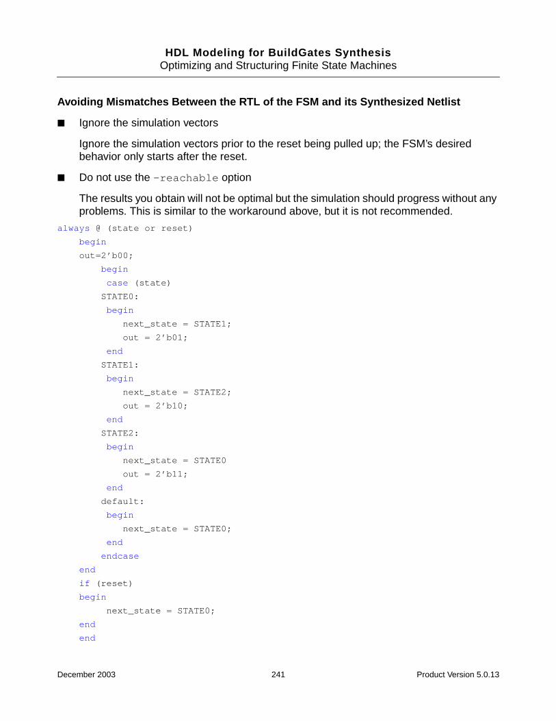
HDL Modeling for BuildGates SynthesisOptimizing and Structuring Finite State Machines
Avoiding Mismatches Between the RTL of the FSM and its Synthesized Netlist
■ Ignore the simulation vectors
Ignore the simulation vectors prior to the reset being pulled up; the FSM’s desiredbehavior only starts after the reset.
■ Do not use the -reachable option
The results you obtain will not be optimal but the simulation should progress without anyproblems. This is similar to the workaround above, but it is not recommended.
always @ (state or reset)
begin
out=2’b00;
begin
case (state)
STATE0:
begin
next_state = STATE1;
out = 2’b01;
end
STATE1:
begin
next_state = STATE2;
out = 2’b10;
end
STATE2:
begin
next_state = STATE0
out = 2’b11;
end
default:
begin
next_state = STATE0;
end
endcase
end
if (reset)
begin
next_state = STATE0;
end
end
December 2003 241 Product Version 5.0.13

HDL Modeling for BuildGates SynthesisOptimizing and Structuring Finite State Machines
The code above shows the default value of out as 00. If the -reachable flag is set, thedefault case is optimized and the value of out is assumed to be 2’bxx. When the simulationstarts, the value of out will always be 2’bxx (unknown). The problem with the design is thatit does not initialize out in the reset block. The simulator interprets the default value of outas 2’b00 in the RTL, but BuildGates Synthesis removes it during optimization using the -reachable option.
■ Unknown values persist in the simulation output
If x (unknown) values persist in the simulation output of the synthesized design (but notin the RTL simulation) after the reset is asserted, then most likely a problem in the RTLdesign needs to be fixed. The x values usually die a few cycles after the reset, after whichthe synthesized netlist behaves identically to the RTL design.
Checking whether the Extracted FSM is Fault-Tolerant
The extracted FSM is fault-tolerant if every state of the FSM transitions to a specified state.This can be verified by checking that every state in the state transition table transitions to aspecified or valid state, or checking that all terminal states are valid states.
Verplex Conformal Logical Equivalency Checker
If you are using the Verplex Conformal Logical Equivalency Checker (LEC) to functionallyverify your design, refer to Appendix B, “Functional Verification with Verplex,” for moreinformation including a list of non-equivalency scenarios with resolution suggestions.
December 2003 242 Product Version 5.0.13
HDL Modeling for BuildGates SynthesisOptimizing and Structuring Finite State Machines
Troubleshooting
Additional troubleshooting information can be found in the latest version of Known Problemsand Solutions for BuildGates Synthesis and Cadence PKS that came with your release.
■ Mux Inference Pragma is not Honored in a Finite State Machine on page 244
■ A 3 state FSM Causes do_build_generic to Crash when extract_fsm is On onpage 244
■ Setting FSM Compile Directives for a VHDL Finite State on page 244
■ State Machine Extraction Fails, by either Hanging or Running Out of Memory onpage 245
■ Coding State Machines in VHDL on page 245
■ FSM Extraction Fails in the Presence of Incompletely Assigned Registers on page 246
December 2003 243 Product Version 5.0.13

HDL Modeling for BuildGates SynthesisOptimizing and Structuring Finite State Machines
Mux Inference Pragma is not Honored in a Finite State Machine
The Mux inference pragma is not honored in FSM. The FSM extraction takes precedenceover the Mux pragma. This is true even when you use or do not use extract_fsm.
A 3 state FSM Causes do_build_generic to Crash when extract_fsmis On
If you can get do_build_generic -extract_fsm to work up to a 20-bit wide stateregister, but the tool crashes when you define the state register to be 24 bits, add the-reachable switch to the state_vector pragma:
//ambit synthesis state_vector state -encoding timing -reachable
This treats unreachable states as don’t cares, which dramatically reduces run-time.
Setting FSM Compile Directives for a VHDL Finite State
See Error During do_build_generic if Design Architecture is not Specified on page 214for information.
December 2003 244 Product Version 5.0.13
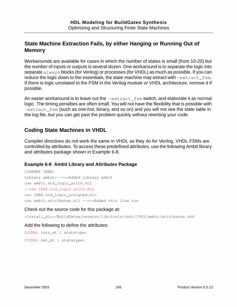
HDL Modeling for BuildGates SynthesisOptimizing and Structuring Finite State Machines
State Machine Extraction Fails, by either Hanging or Running Out ofMemory
Workarounds are available for cases in which the number of states is small (from 10-20) butthe number of inputs or outputs is several dozen. One workaround is to separate the logic intoseparate always blocks (for Verilog) or processes (for VHDL) as much as possible. If you canreduce the logic down to the essentials, the state machine may extract with -extract_fsm.If there is logic unrelated to the FSM in the Verilog module or VHDL architecture, remove it ifpossible.
An easier workaround is to leave out the -extract_fsm switch, and elaborate it as normallogic. The timing penalties are often small. You will not have the flexibility that is possible with-extract_fsm (such as one-hot, binary, and so on) and you will not see the state table inthe log file, but you can get past the problem quickly without rewriting your code.
Coding State Machines in VHDL
Compiler directives do not work the same in VHDL as they do for Verilog. VHDL FSMs arecontrolled by attributes. To access these predefined attributes, use the following Ambit libraryand attributes package shown in Example 6-8.
Example 6-8 Ambit Library and Attributes PackageLIBRARY IEEE;
Library ambit;--<<<Added Library ambit
use ambit.std_logic_arith.ALL
--use IEEE.std_logic arith.ALL
use IEEE.std_logic_unsigned.ALL
use ambit.attributes.all --<<<Added this line too
Check out the source code for this package at:
<install_dir>/BuildGates/version/lib/tools/vhdl/1993/ambit/attributes.vhd
Add the following to define the attributes:
SIGNAL curr_st : statetype;
SIGNAL nxt_st : statetype;
December 2003 245 Product Version 5.0.13

HDL Modeling for BuildGates SynthesisOptimizing and Structuring Finite State Machines
FSM Extraction Fails in the Presence of Incompletely Assigned Registers
You want to extract an FSM only for arb_state but the FSM extraction engine also tries toextract an FSM for burst_counter, which is incompletely assigned, as shown inExample 6-9. As a result, no FSM is extracted. This is a limitation of the FSM extractionengine.
The reason that tool looks at the burst_counter FSM is because it is in the same processwith the arb_state FSM. As long as the arb_state FSM is in a separate process, thenwhether the burst_counter is complete or not, the tool can extract a FSM for arb_statecorrectly. Either assign burst_counter completely or make sure that arb_state andburst_counter are in separate processes.
If burst_counter is assigned in all branches of the case statement of theburst_process, as shown in Example 6-10 the FSM is extracted.
Example 6-9 FSM extraction fails due to incompletely assigned "burst_counter"library ieee,ambit;
use ieee.std_logic_1164.all;
use ieee.std_logic_unsigned.all;
use ambit.attributes.all;
entity arbiter is
port (
resetn : in std_logic;
clk : in std_logic;
acks : in std_logic_vector(1 downto 0);
burst : out std_logic_vector(2 downto 0);
arb : out std_logic_vector(2 downto 0)
);
end arbiter;
architecture synth of arbiter is
signal arb_state : std_logic_vector(2 downto 0);
SIGNAL next_arb_state : std_logic_vector(2 downto 0);
SIGNAL burst_counter : std_logic_vector(2 downto 0);
ATTRIBUTE STATE_VECTOR of arb_state : signal is true;
ATTRIBUTE ENCODING of arb_state : signal is "one_hot";
ATTRIBUTE SYNC_SET_RESET of resetn: signal is true;
begin
December 2003 246 Product Version 5.0.13
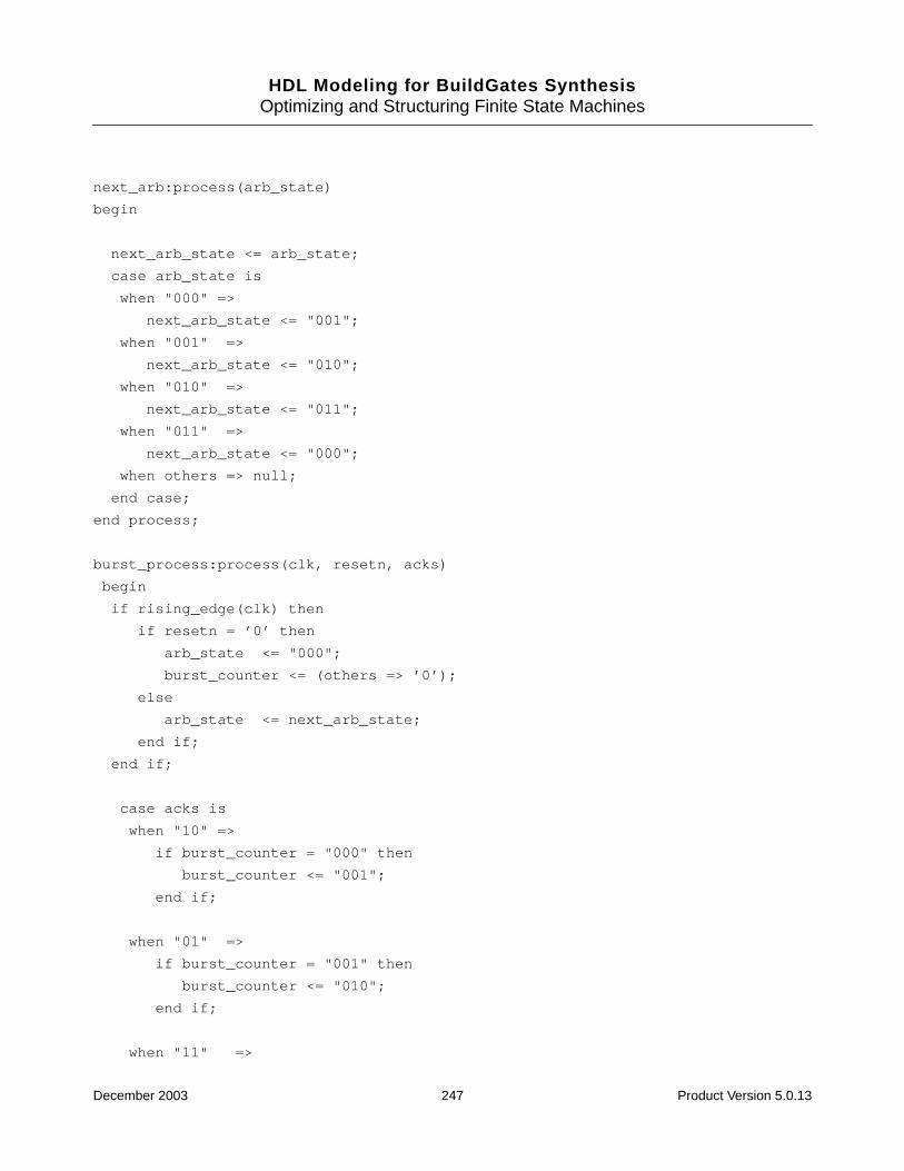
HDL Modeling for BuildGates SynthesisOptimizing and Structuring Finite State Machines
next_arb:process(arb_state)
begin
next_arb_state <= arb_state;
case arb_state is
when "000" =>
next_arb_state <= "001";
when "001" =>
next_arb_state <= "010";
when "010" =>
next_arb_state <= "011";
when "011" =>
next_arb_state <= "000";
when others => null;
end case;
end process;
burst_process:process(clk, resetn, acks)
begin
if rising_edge(clk) then
if resetn = ’0’ then
arb_state <= "000";
burst_counter <= (others => ’0’);
else
arb_state <= next_arb_state;
end if;
end if;
case acks is
when "10" =>
if burst_counter = "000" then
burst_counter <= "001";
end if;
when "01" =>
if burst_counter = "001" then
burst_counter <= "010";
end if;
when "11" =>
December 2003 247 Product Version 5.0.13
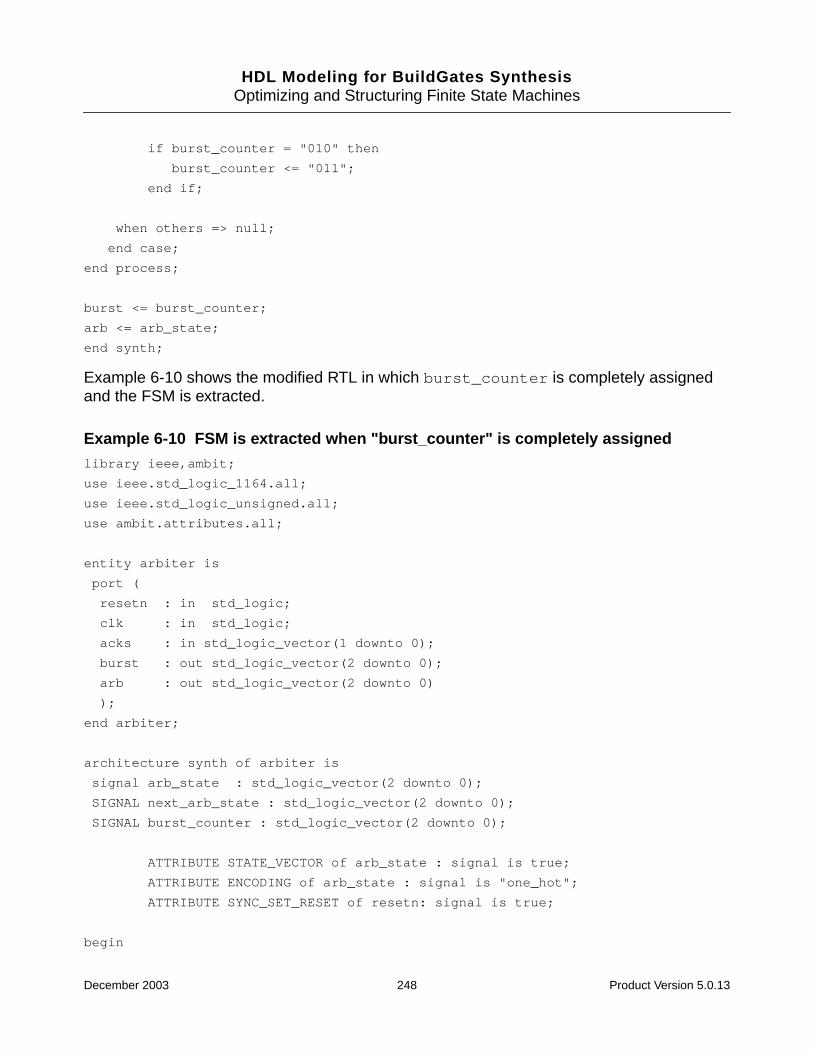
HDL Modeling for BuildGates SynthesisOptimizing and Structuring Finite State Machines
if burst_counter = "010" then
burst_counter <= "011";
end if;
when others => null;
end case;
end process;
burst <= burst_counter;
arb <= arb_state;
end synth;
Example 6-10 shows the modified RTL in which burst_counter is completely assignedand the FSM is extracted.
Example 6-10 FSM is extracted when "burst_counter" is completely assignedlibrary ieee,ambit;
use ieee.std_logic_1164.all;
use ieee.std_logic_unsigned.all;
use ambit.attributes.all;
entity arbiter is
port (
resetn : in std_logic;
clk : in std_logic;
acks : in std_logic_vector(1 downto 0);
burst : out std_logic_vector(2 downto 0);
arb : out std_logic_vector(2 downto 0)
);
end arbiter;
architecture synth of arbiter is
signal arb_state : std_logic_vector(2 downto 0);
SIGNAL next_arb_state : std_logic_vector(2 downto 0);
SIGNAL burst_counter : std_logic_vector(2 downto 0);
ATTRIBUTE STATE_VECTOR of arb_state : signal is true;
ATTRIBUTE ENCODING of arb_state : signal is "one_hot";
ATTRIBUTE SYNC_SET_RESET of resetn: signal is true;
begin
December 2003 248 Product Version 5.0.13

HDL Modeling for BuildGates SynthesisOptimizing and Structuring Finite State Machines
next_arb:process(arb_state)
begin
next_arb_state <= arb_state;
case arb_state is
when "000" =>
next_arb_state <= "001";
when "001" =>
next_arb_state <= "010";
when "010" =>
next_arb_state <= "011";
when "011" =>
next_arb_state <= "000";
when others => null;
end case;
end process;
burst_process:process(clk, resetn, acks)
begin
if rising_edge(clk) then
if resetn = ’0’ then
arb_state <= "000";
burst_counter <= (others => ’0’);
else
arb_state <= next_arb_state;
end if;
end if;
case acks is
when "10" =>
if burst_counter = "000" then
burst_counter <= "001";
else
burst_counter <= "000";
end if;
when "01" =>
if burst_counter = "001" then
December 2003 249 Product Version 5.0.13
HDL Modeling for BuildGates SynthesisOptimizing and Structuring Finite State Machines
burst_counter <= "010";
else
burst_counter <= "000";
end if;
when "11" =>
if burst_counter = "010" then
burst_counter <= "011";
else
burst_counter <= "000";
end if;
when others => burst_counter <= "000";
end case;
end process;
burst <= burst_counter;
arb <= arb_state;
end synth;
December 2003 250 Product Version 5.0.13

HDL Modeling for BuildGates Synthesis
7Using the EDIF Interface
This chapter provides an overview of the EDIF (Electronic Data Interchange Format)interface, explains how to read an EDIF v2.0.0 file, write out designs in EDIF format, and howto represent power and ground in EDIF in the following sections:
■ Overview on page 252
■ Tasks on page 252
■ Troubleshooting on page 263
December 2003 251 Product Version 5.0.13
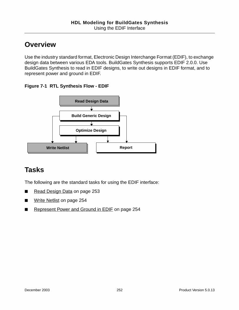
HDL Modeling for BuildGates SynthesisUsing the EDIF Interface
Overview
Use the industry standard format, Electronic Design Interchange Format (EDIF), to exchangedesign data between various EDA tools. BuildGates Synthesis supports EDIF 2.0.0. UseBuildGates Synthesis to read in EDIF designs, to write out designs in EDIF format, and torepresent power and ground in EDIF.
Figure 7-1 RTL Synthesis Flow - EDIF
Tasks
The following are the standard tasks for using the EDIF interface:
■ Read Design Data on page 253
■ Write Netlist on page 254
■ Represent Power and Ground in EDIF on page 254
Read Design Data
ReportWrite Netlist
Build Generic Design
Optimize Design
December 2003 252 Product Version 5.0.13
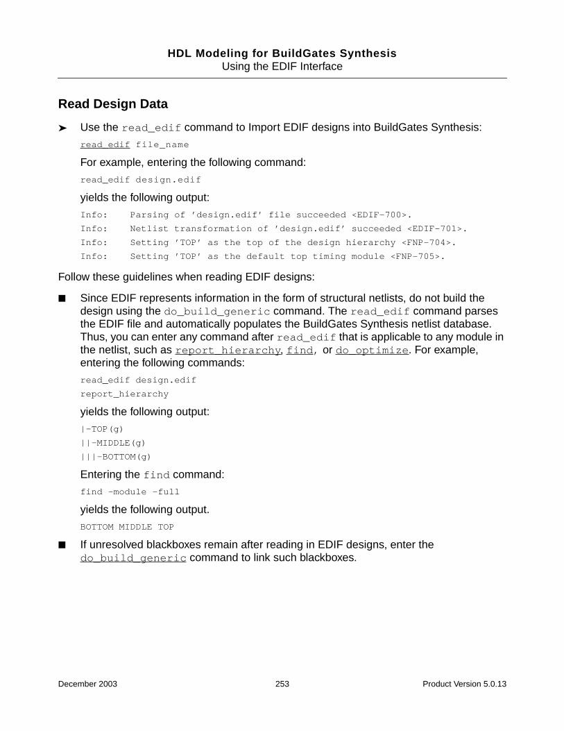
HDL Modeling for BuildGates SynthesisUsing the EDIF Interface
Read Design Data
➤ Use the read_edif command to Import EDIF designs into BuildGates Synthesis:
read_edif file_name
For example, entering the following command:
read_edif design.edif
yields the following output:
Info: Parsing of ’design.edif’ file succeeded <EDIF-700>.
Info: Netlist transformation of ’design.edif’ succeeded <EDIF-701>.
Info: Setting ’TOP’ as the top of the design hierarchy <FNP-704>.
Info: Setting ’TOP’ as the default top timing module <FNP-705>.
Follow these guidelines when reading EDIF designs:
■ Since EDIF represents information in the form of structural netlists, do not build thedesign using the do_build_generic command. The read_edif command parsesthe EDIF file and automatically populates the BuildGates Synthesis netlist database.Thus, you can enter any command after read_edif that is applicable to any module inthe netlist, such as report_hierarchy, find, or do_optimize. For example,entering the following commands:
read_edif design.edif
report_hierarchy
yields the following output:
|-TOP(g)
||-MIDDLE(g)
|||-BOTTOM(g)
Entering the find command:
find -module -full
yields the following output.
BOTTOM MIDDLE TOP
■ If unresolved blackboxes remain after reading in EDIF designs, enter thedo_build_generic command to link such blackboxes.
December 2003 253 Product Version 5.0.13
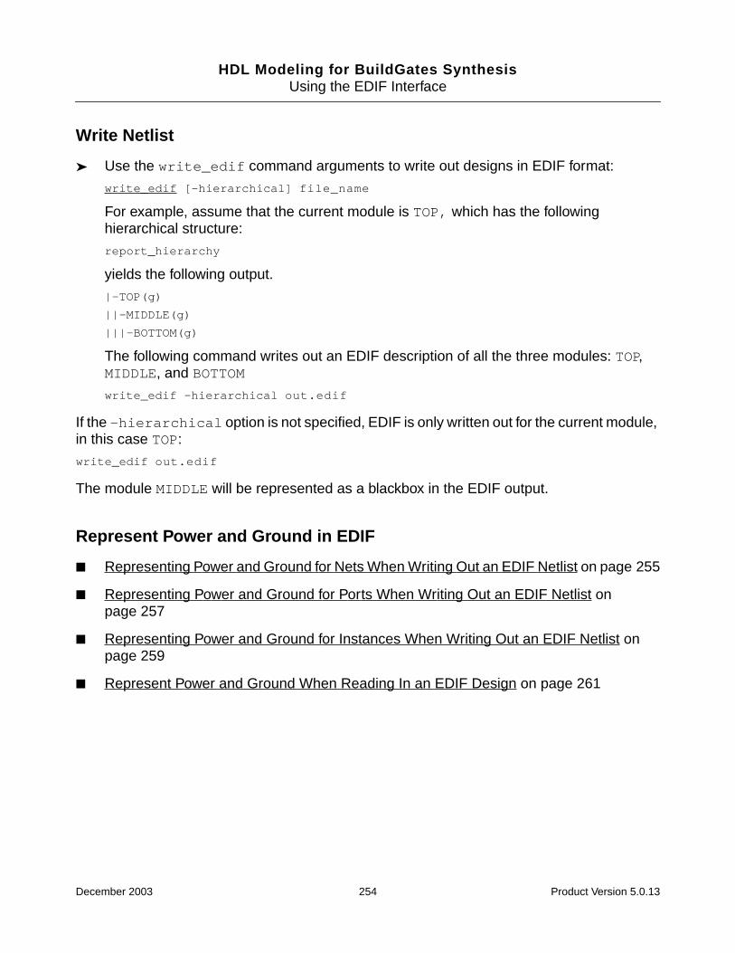
HDL Modeling for BuildGates SynthesisUsing the EDIF Interface
Write Netlist
➤ Use the write_edif command arguments to write out designs in EDIF format:
write_edif [-hierarchical] file_name
For example, assume that the current module is TOP, which has the followinghierarchical structure:
report_hierarchy
yields the following output.
|-TOP(g)
||-MIDDLE(g)
|||-BOTTOM(g)
The following command writes out an EDIF description of all the three modules: TOP,MIDDLE, and BOTTOM
write_edif -hierarchical out.edif
If the -hierarchical option is not specified, EDIF is only written out for the current module,in this case TOP:
write_edif out.edif
The module MIDDLE will be represented as a blackbox in the EDIF output.
Represent Power and Ground in EDIF
■ Representing Power and Ground for Nets When Writing Out an EDIF Netlist on page 255
■ Representing Power and Ground for Ports When Writing Out an EDIF Netlist onpage 257
■ Representing Power and Ground for Instances When Writing Out an EDIF Netlist onpage 259
■ Represent Power and Ground When Reading In an EDIF Design on page 261
December 2003 254 Product Version 5.0.13
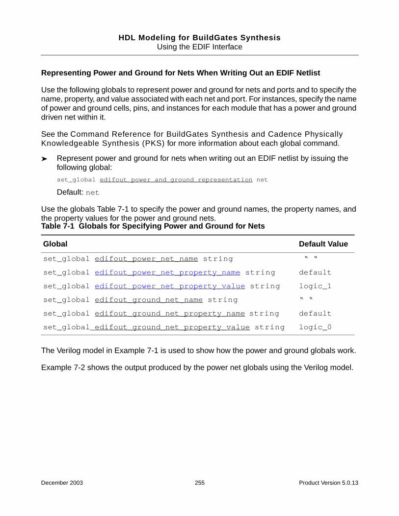
HDL Modeling for BuildGates SynthesisUsing the EDIF Interface
Representing Power and Ground for Nets When Writing Out an EDIF Netlist
Use the following globals to represent power and ground for nets and ports and to specify thename, property, and value associated with each net and port. For instances, specify the nameof power and ground cells, pins, and instances for each module that has a power and grounddriven net within it.
See the Command Reference for BuildGates Synthesis and Cadence PhysicallyKnowledgeable Synthesis (PKS) for more information about each global command.
➤ Represent power and ground for nets when writing out an EDIF netlist by issuing thefollowing global:
set_global edifout_power_and_ground_representation net
Default: net
Use the globals Table 7-1 to specify the power and ground names, the property names, andthe property values for the power and ground nets.
The Verilog model in Example 7-1 is used to show how the power and ground globals work.
Example 7-2 shows the output produced by the power net globals using the Verilog model.
Table 7-1 Globals for Specifying Power and Ground for Nets
Global Default Value
set_global edifout_power_net_name string “ “
set_global edifout_power_net_property_name string default
set_global edifout_power_net_property_value string logic_1
set_global edifout_ground_net_name string “ “
set_global edifout_ground_net_property_name string default
set_global edifout_ground_net_property_value string logic_0
December 2003 255 Product Version 5.0.13
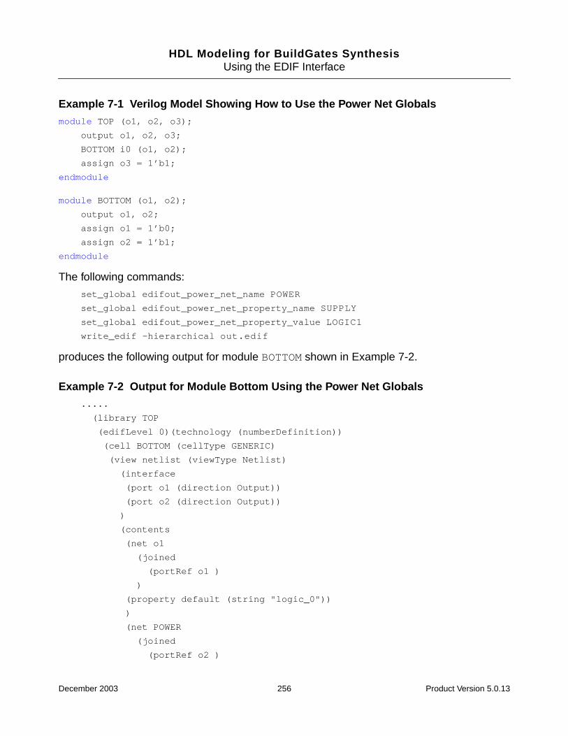
HDL Modeling for BuildGates SynthesisUsing the EDIF Interface
Example 7-1 Verilog Model Showing How to Use the Power Net Globalsmodule TOP (o1, o2, o3);
output o1, o2, o3;
BOTTOM i0 (o1, o2);
assign o3 = 1’b1;
endmodule
module BOTTOM (o1, o2);
output o1, o2;
assign o1 = 1’b0;
assign o2 = 1’b1;
endmodule
The following commands:
set_global edifout_power_net_name POWER
set_global edifout_power_net_property_name SUPPLY
set_global edifout_power_net_property_value LOGIC1
write_edif -hierarchical out.edif
produces the following output for module BOTTOM shown in Example 7-2.
Example 7-2 Output for Module Bottom Using the Power Net Globals.....
(library TOP
(edifLevel 0)(technology (numberDefinition))
(cell BOTTOM (cellType GENERIC)
(view netlist (viewType Netlist)
(interface
(port o1 (direction Output))
(port o2 (direction Output))
)
(contents
(net o1
(joined
(portRef o1 )
)
(property default (string "logic_0"))
)
(net POWER
(joined
(portRef o2 )
December 2003 256 Product Version 5.0.13

HDL Modeling for BuildGates SynthesisUsing the EDIF Interface
)
(property SUPPLY (string "LOGIC1"))
)
)
)
)
.....
Since port o2 is driven to logic 1, the corresponding power net has been named POWER andthe appropriate property attached to it. In the EDIF output above, since no values werespecified for the three ground related globals, the ground net o1 retains its original name andhas the default property attached to it.
Representing Power and Ground for Ports When Writing Out an EDIF Netlist
➤ Represent power and ground for ports when writing out an EDIF netlist by entering thefollowing global command:
set_global edifout_power_and_ground_representation port
Default: net
Use the globals in Table 7-2 to specify the power and ground port names while reading outEDIF designs.
Example 7-3 shows the EDIF output produced using the following port power and groundglobals using the Verilog model shown in Example 7-1.
set_global edifout_power_port_name SUPPLY1
set_global edifout_ground_port_name SUPPLY0
write_edif -hierarchical out.edif
Table 7-2 Globals for Representing Power and Ground for Ports
Global Default Value
set_global edifout_ground_port_name string GND
set_global edifout_power_port_name string PWR
December 2003 257 Product Version 5.0.13

HDL Modeling for BuildGates SynthesisUsing the EDIF Interface
Example 7-3 Output for EDIF Using Port Power and Ground Globals(cell BOTTOM (cellType GENERIC)
(view netlist (viewType Netlist)
(interface
(port SUPPLY0 (direction Input))
(port SUPPLY1 (direction Input))
(port o1 (direction Output))
(port o2 (direction Output))
)
(contents
(net o2
(joined
(portRef SUPPLY1)
(portRef o2 )
)
(property default (string "logic_1"))
)
(net o1
(joined
(portRef SUPPLY0)
(portRef o1 )
)
(property default (string "logic_0"))
)
)
)
)
(cell TOP (cellType GENERIC)
(view netlist (viewType Netlist)
(interface
(port SUPPLY1 (direction Input))
(port o1 (direction Output))
(port o2 (direction Output))
(port o3 (direction Output))
)
......
)
The logic 0 and logic 1 values can be supplied to the logic within the module through the twoports of BOTTOM, SUPPLY0 and SUPPLY1.
December 2003 258 Product Version 5.0.13
HDL Modeling for BuildGates SynthesisUsing the EDIF Interface
Note: Since the module TOP did not have any ground logic within it, no SUPPLY0 port wasadded to its EDIF representation.
Representing Power and Ground for Instances When Writing Out an EDIF Netlist
➤ Represent power and ground for instances when writing out an EDIF netlist by enteringthe following global command:
set_global edifout_power_and_ground_representation instance
Default: net
With this setting, all power or ground are represented as instances of power and ground cells.
The following globals determine the name of power and ground cells as well as pin andinstance names for each module that has a power and ground driven net within it.
Example 7-4 shows the output produced by using the following power and ground globals forinstances using the Verilog model shown in Example 7-1.
[1]>set_global edifout_power_cell_name PWRC
[2]>set_global edifout_power_pin_name PWRP
[3]>set_global edifout_power_instance_name PWRI
[4]>set_global edifout_ground_cell_name GNDC
[5]>set_global edifout_ground_pin_name GNDP
[6]>set_global edifout_ground_instance_name GNDI
[7]>write_edif -hierarchical out.edif
Table 7-3 EDIF Globals for Specifying an Instance
Global Default Value
set_global edifout_power_cell_name string PWR
set_global edifout_power_pin_name string PWR
set_global edifout_power_instance_name string PWR
set_global edifout_ground_cell_name string GND
set_global edifout_ground_pin_name string GND
December 2003 259 Product Version 5.0.13

HDL Modeling for BuildGates SynthesisUsing the EDIF Interface
Example 7-4 Edif Output Using Power and Ground Globals(library TOP
(edifLevel 0)(technology (numberDefinition))
(cell PWRC (cellType GENERIC)
(view netlist (viewType Netlist)
(interface
(port PWRP (direction Output))
)
(cell GNDC (cellType GENERIC)
(view netlist (viewType Netlist)
(interface
(port GNDP (direction Output))
)
(cell BOTTOM (cellType GENERIC)
(view netlist (viewType Netlist)
(interface
(port o1 (direction Output))
(port o2 (direction Output))
)
(contents
(instance PWRI
(viewRef netlist (cellRef PWRC))
)
(instance GNDI
(viewRef netlist (cellRef GNDC))
)
(net o2
(joined
(portRef PWRP (instanceRef PWRI))
(portRef o2 )
)
(property default (string "logic_1"))
)
(net o1
(joined
(portRef GNDP (instanceRef GNDI))
(portRef o1 )
)
(property default (string "logic_0")
December 2003 260 Product Version 5.0.13
HDL Modeling for BuildGates SynthesisUsing the EDIF Interface
Two cells PWRC and GNDC with pins PWRP and GNDP, respectively have been added. Powerand ground within module BOTTOM is represented as instances of these cells.
Represent Power and Ground When Reading In an EDIF Design
Use the following globals to specify a net, port, and instance representation for power andground while reading in EDIF designs.
Globals for Specifying a Net Default Value
set_globaledifin_power_and_ground_representation net
net
set_global edifin_power_net_name string “ “
set_global edifin_power_net_property_namestring
default
set_global edifin_power_net_property_valuestring
logic_1
set_global edifin_ground_net_name string “ “
set_global edifin_ground_net_property_namestring
default
set_global edifin_ground_net_property_valuestring
logic_0
Globals for Specifying a Port Default Value
set_globaledifin_power_and_ground_representation port
net
set_global edifin_power_port_name string PWR
set_global edifin_ground_port_name string GND
Globals for Specifying an Instance Default Value
set_globaledifin_power_and_ground_representationinstance
net
set_global edifin_power_pin_name string PWR
December 2003 261 Product Version 5.0.13
HDL Modeling for BuildGates SynthesisUsing the EDIF Interface
set_global edifin_power_instance_name string PWR
set_global edifin_ground_pin_name string GND
set_global edifin_ground_instance_name string GND
Globals for Specifying an Instance Default Value
December 2003 262 Product Version 5.0.13

HDL Modeling for BuildGates SynthesisUsing the EDIF Interface
Troubleshooting
Additional troubleshooting information can be found in the latest version of Known Problemsand Solutions for BuildGates Synthesis and Cadence PKS that accompanied yourrelease.
How to Export an EDIF Schematic for Viewing in a Different Tool
By default, the write_edif command creates a netlist-only EDIF file that does not containgraphical information for the schematic.
EDIF netlists containing schematics can be read into the ICCA tool (version IICC4.45) usingthe edifin tool. The schematic can then be viewed in the Cadence DFII environment.
There is a method within BuildGates Synthesis for generating an EDIF file containing both anetlist representation and a schematic representation, but it can only be used from theBuildGates GUI (bg_shell -gui). It is not available from the textual bg_shell interface.You need a symbol library (.slib) for viewing the schematic in the BuildGates GUI.
➤ The Schematic window can be exported to an EDIF 2.0.0 format by entering the followingcommand in the GUI bg_shell:
$vBGates(sch_active_window)write_edif -file filename [-indent -orcad -mono]
vBGates(sch_active_window) is an internal variable that stores the widget ID forthe current active schematic.
The following options are available:
■ Indent formats the file for readability by inserting spaces. This option can double theEDIF file size.
■ Orcad creates an EDIF schematic suitable for Orcad tools that may not be readable byother programs.
Mono causes the schematic to be displayed in black and white.
December 2003 263 Product Version 5.0.13

HDL Modeling for BuildGates SynthesisUsing the EDIF Interface
December 2003 264 Product Version 5.0.13
HDL Modeling for BuildGates Synthesis
AAmbitWare
This appendix includes the following information:
■ Introduction on page 266
■ AmbitWare Flow on page 268
■ AmbitWare Generators on page 269
■ AmbitWare Libraries on page 276
December 2003 265 Product Version 5.0.13
HDL Modeling for BuildGates SynthesisAmbitWare
Introduction
An essential part of building a generic netlist from an RTL description is generatingimplementations for the various datapath elements, multiplexers, Boolean gates, andcomplex operations such as encoders, decoders, and pipelined multipliers. BuildGatesSynthesis uses the AmbitWare collection of module generators and pre-defined RTL librariesto implement these operations. The generators are used to build inferred components. Thelibraries contain the encrypted macro components written in RTL that are directly instantiatedin the source RTL.The inferred or instantiated components are automatically built duringsynthesis, taking into account the technology library information and design constraints.
AmbitWare contains five generators and three pre-defined libraries.Table A-1 shows the usemodel and lists whether the generator or library is technology independent, and whether theDatapath license is required.
Generators
■ AmbitWare Arithmetic Component Library Generator (AWACL) — Default generatorused for realizing technology independent implementations for basic arithmeticoperations in the RTL, such as addition, subtraction, multiplication, shifts, increments,decrements, and comparisons.
■ AmbitWare Datapath Generator (AWDP) — Used for generating more efficienttechnology dependent implementations for the basic arithmetic operations, andimplementations for clusters of merged arithmetic operations (such as generating acarry-save implementation for a chain of additions). The Datapath generator generatesgeneric components during do_build_generic, but generates technology mappedcomponents during mapping and optimization. It makes micro architectural trade-offsbased on libraries.
■ AmbitWare Multiplexer Generator (AWMUX) — Used to generate general N-to-1, M-bitwide multiplexer implementations that may be required during the generic build.
■ AmbitWare Sum-of-Products (AWSOP)— Used to extract logic from case statements.
■ AmbitWare Resource Shared Module Generator (AWRS) — Used to implement one ormore AmbitWare modules into one shared module.
December 2003 266 Product Version 5.0.13
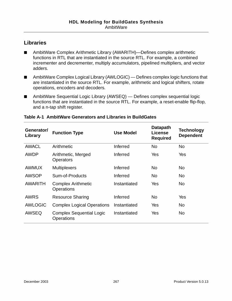
HDL Modeling for BuildGates SynthesisAmbitWare
Libraries
■ AmbitWare Complex Arithmetic Library (AWARITH)—Defines complex arithmeticfunctions in RTL that are instantiated in the source RTL. For example, a combinedincrementer and decrementer, multiply accumulators, pipelined multipliers, and vectoradders.
■ AmbitWare Complex Logical Library (AWLOGIC) — Defines complex logic functions thatare instantiated in the source RTL. For example, arithmetic and logical shifters, rotateoperations, encoders and decoders.
■ AmbitWare Sequential Logic Library (AWSEQ) — Defines complex sequential logicfunctions that are instantiated in the source RTL. For example, a reset-enable flip-flop,and a n-tap shift register.
Table A-1 AmbitWare Generators and Libraries in BuildGates
Generator/Library Function Type Use Model
DatapathLicenseRequired
TechnologyDependent
AWACL Arithmetic Inferred No No
AWDP Arithmetic, MergedOperators
Inferred Yes Yes
AWMUX Multiplexers Inferred No No
AWSOP Sum-of-Products Inferred No No
AWARITH Complex ArithmeticOperations
Instantiated Yes No
AWRS Resource Sharing Inferred No Yes
AWLOGIC Complex Logical Operations Instantiated Yes No
AWSEQ Complex Sequential LogicOperations
Instantiated Yes No
December 2003 267 Product Version 5.0.13
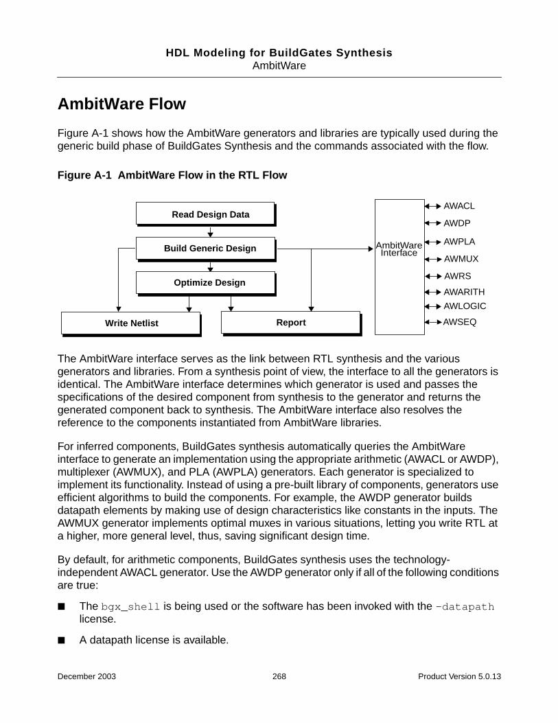
HDL Modeling for BuildGates SynthesisAmbitWare
AmbitWare Flow
Figure A-1 shows how the AmbitWare generators and libraries are typically used during thegeneric build phase of BuildGates Synthesis and the commands associated with the flow.
Figure A-1 AmbitWare Flow in the RTL Flow
The AmbitWare interface serves as the link between RTL synthesis and the variousgenerators and libraries. From a synthesis point of view, the interface to all the generators isidentical. The AmbitWare interface determines which generator is used and passes thespecifications of the desired component from synthesis to the generator and returns thegenerated component back to synthesis. The AmbitWare interface also resolves thereference to the components instantiated from AmbitWare libraries.
For inferred components, BuildGates synthesis automatically queries the AmbitWareinterface to generate an implementation using the appropriate arithmetic (AWACL or AWDP),multiplexer (AWMUX), and PLA (AWPLA) generators. Each generator is specialized toimplement its functionality. Instead of using a pre-built library of components, generators useefficient algorithms to build the components. For example, the AWDP generator buildsdatapath elements by making use of design characteristics like constants in the inputs. TheAWMUX generator implements optimal muxes in various situations, letting you write RTL ata higher, more general level, thus, saving significant design time.
By default, for arithmetic components, BuildGates synthesis uses the technology-independent AWACL generator. Use the AWDP generator only if all of the following conditionsare true:
■ The bgx_shell is being used or the software has been invoked with the -datapathlicense.
■ A datapath license is available.
AmbitWareInterface
AWACL
AWDP
AWPLA
AWARITH
AWLOGIC
AWSEQ
AWMUX
AWRS
Read Design Data
ReportWrite Netlist
Build Generic Design
Optimize Design
December 2003 268 Product Version 5.0.13
HDL Modeling for BuildGates SynthesisAmbitWare
The name of the generator used to generate components is prefixed to the name of thegenerated component. For example, the AWACL generator implements an additionoperation, generates the adder module name, and prefixes AWACL. If the AWDP generatorimplemented same addition operation, AWDP would be prefixed in the generated addermodule name.
For instantiated AmbitWare components, BuildGates automatically queries the AmbitWareInterface that resolves the reference to the component using AWARITH, AWLOGIC, AWSEQ,and user-defined libraries. Once the component definition is known, the AmbitWare Interfaceuses the generators to build it in the same way as any RTL design.
The following sections provide details on each of the AmbitWare generators and the variousways their functions can be manipulated in BuildGates. Use the pre-defined AmbitWarelibraries that accompany BuildGates or create and use your own AmbitWare libraries.
AmbitWare Generators
■ AWACL Generator on page 270
■ AWDP Generator on page 271
■ AWMUX Generator on page 273
■ AWSOP Generator on page 274
■ AWRS Generator on page 275
December 2003 269 Product Version 5.0.13

HDL Modeling for BuildGates SynthesisAmbitWare
AWACL Generator
Use the AWACL generator to synthesize the following basic arithmetic datapath operators:
unary minus, +, -, *, arithmetic shift right, logical shift right, shift left,rotate left,rotate right, >, <, >=, <=, ==, !=, absolute value.
The AWACL generator synthesizes each operator separately and generates a technologyindependent netlist. The generated components have names that start with AWACL_.
Note: The AWACL generator comes with BuildGates and PKS and does not require theDatapath license.
Use the following tasks to control the functioning of the AWACL generator.
Changing the Architecture
➤ Use the following global variables to set the default adder architecture for final adders:
set_global aware_adder_architecture {ripple | csel | cla | fcla }
The AWACL generator uses a set of architectures to synthesize the different datapathoperators. For adders and final adders in multipliers, the available architectures are ripple,conditional select (csel), and carry lookahead (cla). The only multiplier-encoding architectureavailable for AWACL multipliers is non-Booth. The components generated using the AWACLgenerator are not subjected to automatic architecture selection during timing optimization.
Setting the Operator Width Limit
➤ Use the following global variable to set the size of components that are dissolved:
set_global aware_dissolve_width positive_integer
Generated components are pre-structured by using architectures for the datapath operators,so they are labeled as optimized and are not structured during optimization. However, smallAWACL components that are below a threshold are dissolved during optimization.
For more information on these global commands refer to the AmbitWare Globals chapter inthe Global Variable Reference Manual for BuildGates Synthesis and Cadence PKS.
December 2003 270 Product Version 5.0.13
HDL Modeling for BuildGates SynthesisAmbitWare
AWDP Generator
Use the AWDP generator to create the following simple and complex arithmetic datapathcomponents:
unary minus, +, -, *, arithmetic shift right, logical shift right, shift left,rotate left, rotate right, >, <, >=, <=, ==, !=, absolute value.
The AWDP generator synthesizes the datapath partitions (created earlier by the process ofpartitioning datapath from control) using specialized optimization techniques that yield betterquality of results (delay, area, power). All the modules generated by the AWDP generatorhave names starting with AWDP_.
Note: The AWDP generator requires the Cadence Datapath Synthesis of BuildGatesSynthesis and PKS license.
The following are the standard tasks to control the functioning of the AWDP generator. Forcomplete details, refer to the AmbitWare Globals chapter in the Global Variable ReferenceManual for BuildGates Synthesis and Cadence PKS.
■ Setting the Operator Width Limit on page 271
■ Implementing Datapath Components on page 272
■ Controlling Operator Merging on page 272
■ Selecting the Adder Architecture on page 272
■ Selecting the Multiplier Architecture on page 273
Setting the Operator Width Limit
➤ Use the following global variable to set the size of components that are dissolved:
set_global aware_dissolve_width positive_integer
Generated components are pre-structured using architectures for the datapath operators.They are labeled as optimized and are not structured during optimization. However, smallcomponents that are below a threshold are dissolved during optimization.
Note: The dissolve width is based on the literal count of the operator and is influenced by thearchitecture. For example: a 16-bit adder implemented using the cla architecture, is about thesame size as a 24-bit ripple adder, therefore the positive integer value should be 24.
December 2003 271 Product Version 5.0.13
HDL Modeling for BuildGates SynthesisAmbitWare
Implementing Datapath Components
➤ Use the following global to automatically implement the datapath elements:
set_global aware_implementation_selection {true | false}
When set to true, the implementation of datapath components are automatically selectedbased on the constraints.
Default: true
The modules generated by the AWDP generator are tagged as swappable and architectureselection is performed on them during timing optimization. Constraint-driven architectureselection attempts to select the best possible architectures under the design constraints forall arithmetic operators. Because faster is not always better (area increases), automaticarchitecture selection keeps the faster (larger) architectures on the critical path and acceptsthe slower (smaller) architectures on non-critical paths.
Controlling Operator Merging
➤ Use the following global to control operator merging:
set_global aware_merge_operators {true | false}
Operator merging is a key datapath optimization that significantly improves the quality ofresults (QOR). Operators are merged (combined) and the complex arithmetic expressionsare synthesized without intermediate carry-propagate adders. Operator merging performsarithmetic simplification to eliminate redundant computations. This usually results in a betterdelay and area implementation. Merging also results in implicit re-balancing of datapathoperations that are in a skewed graph.
Default: true
Selecting the Adder Architecture
➤ Use the following global to set the default adder architecture for final adders:
set_global aware_adder_architecture {ripple | csel | cla | fcla}
The AWDP generator synthesizes four adder architectures: ripple, carry select (csel), carrylookahead (cla) and fast carry lookahead (fcla). AWDP also provides Booth and Non-Boothmultiplier encoding and mux-based and AND/OR-based shifter or rotator architectures.
Default: cla for AWCL and fcla for AWDP
December 2003 272 Product Version 5.0.13

HDL Modeling for BuildGates SynthesisAmbitWare
Selecting the Multiplier Architecture
➤ Use the following global to set the default multiplier architecture for multipliers:
set_global aware_multiplier_architecture {booth | non-booth | auto}
The AWDP generator performs micro-architecture selection based on the availability ofappropriate cells in the technology library. AWDP decides whether to select a Booth or non-Booth multiplier based on the availability of Booth encoding cells in the technology library andthe width and signedness of the input operands.
Default: auto
AWMUX Generator
The AWMUX generator contains the ATL, XATL, and AWARE multiplexers to implementvariables in the RTL description that are assigned values by either if-then-else or casestatements. ATL (Ambit Technology Library) and XATL (Extended Ambit Technology Library)components are pre-defined and are contained in the BuildGates synthesis generic library.AWARE components are automatically generated by the tool as needed.
The AWMUX generator does not require the Cadence Datapath Synthesis of BuildGatesSynthesis and PKS license.
A multiplexer is “complete” when the number of data inputs is 2 to the power of the numberof select inputs that are 1-bit wide. The BuildGates synthesis generic library currentlycontains the following “complete” ATL and XATL multiplexers, shown in Table A-2..
Any additional multiplexers required to implement an RTL description are automaticallygenerated by the AWMUX generator and are made up of ATL, XATL, and AWAREmultiplexers. For example, AWARE multiplexers are generated to implement n-bitmultiplexers, incomplete multiplexers (such as, 10-to-1 mux), and complete multiplexers withmore than 16-data inputs.
Table A-2 Library of Complete ATL and XATL Multiplexers
Complete Multiplexer Function Data Inputs SelectInputs Bit Width
ATL_MUX_21 2-to-1 mux 2 1 1
XATL_MUX_4 4-to-1 mux 4 2 1
XATL_MUX_8 8-to-1 mux 8 3 1
XATL_MUX_16 16-to-1 mux 16 4 1
December 2003 273 Product Version 5.0.13
HDL Modeling for BuildGates SynthesisAmbitWare
The naming convention for AWARE multiplexers is AWMUX_d_bwhere d is the number of datainputs and b is the number of bits. The number of select inputs, s, for AWARE multiplexersis the minimum number required to select the d data inputs, as per the equation:
2s-1 < d < 2s
Setting the Size of the Multiplexer (MUX) to be Dissolved
➤ Use the following global variable to set the size of the multiplexer to be dissolved:
set_global aware_mux_dissolve_size positive integer
BuildGates Synthesis uses multiplexers whenever possible to implement logic for variables inthe RTL design that are assigned values within if-then-else or case statements. Duringthe do_optimize design phase, multiplexers that have less than the number of data inputsspecified by the global aware_mux_dissolve_size are dissolved and optimized within thecontext of surrounding logic. Specialized optimizations are applied to multiplexers that havemore than the number of data inputs specified by aware_mux_dissolve_size. After logicoptimization, if the size of the optimized mux is found to be less than that of theaware_mux_dissolve_size input mux, it is dissolved. In general, synthesis run timeincreases as the aware_mux_dissolve_size increases.
Default: 8
Muxes inferred using the directive infer_mux are not dissolved or optimized.
AWSOP Generator
The AWSOP generator extracts logic from case statements. A variable that is assigned onlyconstant values within a case statement, such as variable z can be represented by aBoolean equation that is in a sum-of-products (SOP) form as shown in Figure 2-8 on page 54.SOP logic that is identified and extracted during the do_build_generic design phase canbe minimized during the do_optimize design phase with specialized and efficient logicoptimization techniques
December 2003 274 Product Version 5.0.13
HDL Modeling for BuildGates SynthesisAmbitWare
Extracting PLAs for Constant Case Statements
➤ Set the following global to true to automatically extract logic from case statements thatcan be represented by Boolean equations in sum-of-products form:
set_global hdl_extract_sum_of_products_logic {true | false}
Default: true
When the hdl_extract_sum_of_products_logic global is set to false, the SOP logicis not identified and extracted. Instead, the logic is minimized within the context ofsurrounding logic using generalized logic optimization techniques.
For large, non-parallel casex or casez statements, faster run-times may be possible if SOPlogic is not extracted
Note: The AWSOP generator does not require the Datapath license.
AWRS Generator
The AWRS Generator creates resource shared (RS) modules that implement two or morearithmetic operations in the HDL. These operations must be present in mutually exclusivesegments of a single HDL conditional construct such as a case or an if statement.
The modules created by this generator are named AWRS_partition_1,AWRS_partition_2, and so on. After timing optimizations, resource sharing is performedincrementally by replacing any two modules in the netlist with a new AWRS module. At thistime, the AWRS generator automatically synthesizes the functionality of the new sharedmodule and replaces the two original unshared modules.
For more details on Resource Sharing, see Chapter 2, “High-Level Optimizations.”
December 2003 275 Product Version 5.0.13
HDL Modeling for BuildGates SynthesisAmbitWare
AmbitWare Libraries
AmbitWare libraries are sets of pre-defined, ready-to-use components that enhance thereusability of the designs and reduce the repeat design effort, thereby improving efficiency.AmbitWare libraries support the intellectual property (IP) use model by containing theencrypted models of components. The synthesis models of the components are defined inVerilog RTL. The simulation models of the components are defined in the Verilog and VHDL.The components are decrypted, synthesized, and optimized in process using the AmbitWaregenerators. As with any RTL design, the synthesis and optimization engines use thetechnology library information and the design constraints to build these components, therebytaking full advantage of the capabilities of synthesis and optimization engine.
BuildGates synthesis contains the pre-defined AWARITH, AWLOGIC, and AWSEQAmbitWare libraries and supports user-defined libraries, all of which are discussed in thefollowing sections.
Note: You must purchase the Datapath license to use the AWARITH, AWLOGIC, andAWSEQ libraries.
All globals that are applicable to RTL design are applicable to the AmbitWare librarycomponents. For complete details, refer to the AmbitWare Globals chapter in the GlobalVariable Reference Manual for BuildGates Synthesis and Cadence PKS.
. The following are the standard tasks to control the functioning of AmbitWare libraries:
■ Setting the Library Search Order on page 277
■ Using Predefined AmbitWare Libraries on page 277
■ Defining Your Own AmbitWare Libraries on page 277
■ Using Synthesis Directives on page 282
December 2003 276 Product Version 5.0.13
HDL Modeling for BuildGates SynthesisAmbitWare
Setting the Library Search Order
➤ Use the following global to set the order in which AWARE libraries are searched:
set_global aware_library_search_order logical names
The aware_library_search_order global is applicable to pre-defined and user-definedlibraries.
Using Predefined AmbitWare Libraries
BuildGates Synthesis contains three pre-defined AmbitWare libraries: AWARITH, AWLOGIC,and AWSEQ. The AWARITH library contains pre-defined complex arithmetic components.The AWLOGIC library contains pre-defined complex logic components, and the AWSEQlibrary contains pre-defined complex sequential logic components. Both synthesis andsimulation models of all the components are provided. The components in these libraries takefull advantage of the synthesis and optimization engines, including advanced datapathtechniques like operator merging and automatic architecture selection.
Use the synthesis directive ambit synthesis architecture in the RTL description tocontrol the architecture. All the synthesis directives that are applicable to a RTL design areapplicable to the AmbitWare library components. Refer to the Synthesis Directives sectionsof either the Verilog Modeling Styles or VHDL Modeling Styles chapters, as required. You canalso use the Tcl command do_change_module_architecture.
Refer to AmbitWare Component Reference for detailed description and usage of theAmbitWare library components.
Defining Your Own AmbitWare Libraries
You can create your own AmbitWare libraries of pre-defined components and use them asyou do with the AmbitWare libraries that ship with the software. The components can bewritten in RTL and encrypted before saving in the library, allowing the exchange oftechnology-independent IP blocks. The components are optimized like any other RTL design.The datapath elements in the components use the AWDP generator techniques such asoperator merging and automatic architecture selection.
The following sections explain how to create and use your own libraries of components. Forcomplete details, refer to the Command Reference for BuildGates Synthesis andCadence PKS.
■ Creating an AmbitWare Library on page 278
■ Using Your Own Libraries on page 279
December 2003 277 Product Version 5.0.13

HDL Modeling for BuildGates SynthesisAmbitWare
■ Deleting a Component From a Library on page 279
■ Disabling a Component on page 279
■ Controlling the Architecture of a Component on page 280
■ Creating a Library Report on page 281
Creating an AmbitWare Library
1. Map the logical name of the library to the existing directory where the analyzedcomponents will physically reside using the following command arguments:
set_aware_library library_name library_path
For example:
set_aware_library AWMYLIB /home/smith/libs/lib1
2. Create the components files in RTL from Verilog or VHDL. One file must contain only onecomponent definition. For example:
Create component files AWMYCOMP1.v, AWMYCOMP2.v, and AWMYCOMP3.vhd andplace in /home/smith/comps.
3. Populate the library with the component file(s) using the read_verilog or read_vhdlcommand. For example:
read_verilog -aware_library aware_libname verilog_filenames
or
read_vhdl -aware_library aware_libname vhdl_filenames
The above example contains both Verilog and VHDL component files:
read_verilog -aware_library AWMYLIB AWMYCOMP1.v AWMYCOMP2.v
read_vhdl -aware_library AWMYLIB AWMYCOMP3.vhd
If a syntax error is detected in the component file(s), correct it and repeat the file readingstep. This step performs the following functions:
❑ Reads the specified component files
❑ Checks the syntax
❑ Generates the corresponding encrypted files (.bd files) in the specified library
❑ Adds an entry for these components in the index file of the library
The library has been created and the components are ready to use.
December 2003 278 Product Version 5.0.13

HDL Modeling for BuildGates SynthesisAmbitWare
Using Your Own Libraries
1. Map the library name to a physical path using the command explained in step 1 above:
set_aware_library library_name library_path
2. Set the order in which the libraries will be searched by using the following global:
set_global aware_library_search_order logical names
When the software reads any design instantiating a component from this library, it willautomatically fetch the component definition from the specified library. If two libraries containa component with the same name, the one found first is used.
Deleting a Component From a Library
➤ Use the following command to delete a component from a library:
delete_aware_component -library library_name component_name
The following example shows how to delete the component AWMYCOMP1 from the libraryAWMYLIB:
delete_aware_component -library AWMYLIB AWMYCOMP1
If the -library option is not specified, the libraries are searched in the order definedby the global aware_library_search_order and the first component that matchesthe specified component is deleted.
➤ To delete all the components of the library AWMYLIB, use the -all option.
delete_aware_component -library library_name -all
Disabling a Component
➤ Use the following command with the dont_utilize argument to disable a componenttemporarily:
set_aware_component_property [-library library_name] dont_utilize {true |false} component_name
For example, making AWMYCOMP1 unavailable for use without deleting lets you share thecomponents selectively:
set_aware_component_property dont_utilize true -library AWMYLIB AWMYCOMP1
December 2003 279 Product Version 5.0.13
HDL Modeling for BuildGates SynthesisAmbitWare
Controlling the Architecture of a Component
Change the architecture of an Ambitware component by using one of the following steps:
1. Specify the architecture of an Ambitware component by using the following Tclcommand:
do_change_module_architecture [-hier] [-adder_architecture{adder arch value}] [-multiplier_architecture {mult arch value}{list of modules}]
where
-adder_architecture: Specifies the final adder architecture used. The valid valuesare ripple, fcla, cla, and csel.
-hier: Applies the command recursively to all the relevant Ambitware sub-modules inthe specified module.
-multiplier_architecture: Specifies the multiplier encoding scheme used. Thevalid values are booth and non_booth. For example:
do_change_module_architecture -adder_architecture fcla-multiplier_architecture booth AWARITH_MULT_ADD_wA8_wB8_wC8_wZ16
Use the Tcl command any time after do_build_generic. The specified Ambitwaremodules will be resynthesized with the specified architecture values and the old moduleswill be replaced with the new ones.
2. Specify the architecture by using the following synthesis directive:
ambit synthesis architecture
Place the directive after the closing parenthesis of the port list and before the final ‘;’. Forexample:
AWARITH_MULT_ADD I1 (a,b,c,t,z)//ambit synthesis architecture=fcla,booth;
The above instantiation synthesizes instance I1 of AWARITH_MULTADD that usesbooth-encoding scheme for the multiplier and fcla architecture for the final carrypropagate adder.
December 2003 280 Product Version 5.0.13
HDL Modeling for BuildGates SynthesisAmbitWare
The specified architecture is applied to all the relevant datapath elements in the instantiatedcomponent. As with other specified architectures, these architectures are not overridden byConstraint Driven Implement Selection during optimization. The following are the values ofthe BuildGates Synthesis architecture directive:
■ fcla
■ cla
■ csel
■ ripple
■ booth
■ non_booth
Creating a Library Report
➤ Use the following command to create a report of an AmbitWare library:
report_aware_library -library lib_name -summary filename -component pattern
If the -summary option is not used, a verbose report is generated.
If the -library option is not used, a report is generated for all the AmbitWare libraries.
If the -component pattern is not specified, all the components in the library arereported.
The following command:
report_aware_library -library AWMYLIB -summary SMITH_FILE -component AWMYCOMP3
generates a summary report named SMITH_FILE of the library AWMYLIB for the componentswhose name matches the pattern AWMYCOMP3 as shown in Figure A-2.
December 2003 281 Product Version 5.0.13

HDL Modeling for BuildGates SynthesisAmbitWare
Figure A-2 Example Library Report
Using Synthesis Directives
All the synthesis directives that are applicable to RTL design are also applicable to theAmbitWare library components. Refer to the Synthesis Directives sections of either theVerilog Modeling Styles or VHDL Modeling Styles chapters, as required.
+------------------------------------+| Report | report_aware_library ||---------+--------------------------|| Options | -library AWLOGIC rpt.log |+---------+--------------------------+| Date | 20010322.123149 || Tool | bg_shell || Release | v5.0-eng || Version | Mar 19 2001 16:58:58 |+------------------------------------++-----------------------------------------------------------------------------------------------------------------+| Library | Directory | Component ||-----------+---------------------------+-------------------------------------------------------------------------|| | | Name | Lang | Prop | File ||-----------+---------------------------+-----------------+-----------+--------------------+----------------------|| AWLOGIC | /vobs/dt_internal/interna | AWLOGIC_ROTATER | sdl | dont_utilize=false | AWLOGIC_ROTATER.sdl.bd || | l/../../dt/release/BuildG | | | | || | ates/version/lib/tools/aw | | | | || | are/syn/AWLOGIC | | | | || | | AWLOGIC_BINENC | sdl | dont_utilize=false | AWLOGIC_BINENC.sdl.bd || | | AWLOGIC_ROTATEL | sdl | dont_utilize=false | AWLOGIC_ROTATEL.sdl.bd || | | AWLOGIC_ASHIFTR | sdl | dont_utilize=false | AWLOGIC_ASHIFTR.sdl.bd || | | AWLOGIC_LSHIFTR | sdl | dont_utilize=false | AWLOGIC_LSHIFTR.sdl.bd || | | AWLOGIC_LZCOUNT | sdl | dont_utilize=false | AWLOGIC_LZCOUNT.sdl.bd || | | AWLOGIC_LSHIFTL | sdl | dont_utilize=false | AWLOGIC_LSHIFTL.sdl.bd || | | AWLOGIC_DECODE | sdl | dont_utilize=false | AWLOGIC_DECODE.sdl.bd |+----------------------------------------------------------------------------------------------------------------
December 2003 282 Product Version 5.0.13

HDL Modeling for BuildGates Synthesis
BFunctional Verification with Verplex
This appendix includes the following information regarding functional verification ofBuildGates netlists with the Verplex Conformal Logical Equivalence Checker (LEC):
■ Introduction on page 284
■ Verplex Conformal Logical Equivalence Checker on page 284
December 2003 283 Product Version 5.0.13

HDL Modeling for BuildGates SynthesisFunctional Verification with Verplex
Introduction
This appendix provides suggestions to those who use the Verplex Conformal LogicEquivalence Checker (LEC) to verify the functional equivalence between an RTL descriptionand the netlist generated by BuildGates for that description.
The BuildGates® Synthesis software generates a hardware implementation from a registertransfer level (RTL) design. Complex algorithms are invoked during synthesis to ensure thebest possible netlist. However, it is both strongly recommended and customary to verify thatthe generated netlist is functionally equivalent to the input RTL description by using eithersimulation or formal verification techniques.
Verplex Conformal Logical Equivalence Checker
Proving functional equivalence between the synthesized netlist and the input RTL designmakes certain assumptions about the functional semantics of the hardware descriptionlanguage (HDL) used for the RTL description. BuildGates supports Verilog and VHDL HDLs,both of which are specified in detail in IEEE Standard Language Reference Manuals.However, despite these detailed HDL specifications, synthesis, simulation, and equivalencechecking tools sometimes make different assumptions about how a Verilog or VHDL RTLdescription should behave as hardware.
Non-Equivalency Resolutions
If Verplex LEC reports that the RTL description and netlist are not equivalent, check thefollowing non-equivalency scenarios and resolutions:
■ Does the netlist contain escaped names?
Type this LEC Setup command:
add renaming rule R1 \\%s @1 -re -map -type pi -type po
■ Does the RTL contain arrays or records?
Type these BuildGates commands prior to issuing the do_build_generic command:
set_global hdl_record_generator "%s\[%s\"
set_global hdl_array_generator "%s\[%d\"
December 2003 284 Product Version 5.0.13
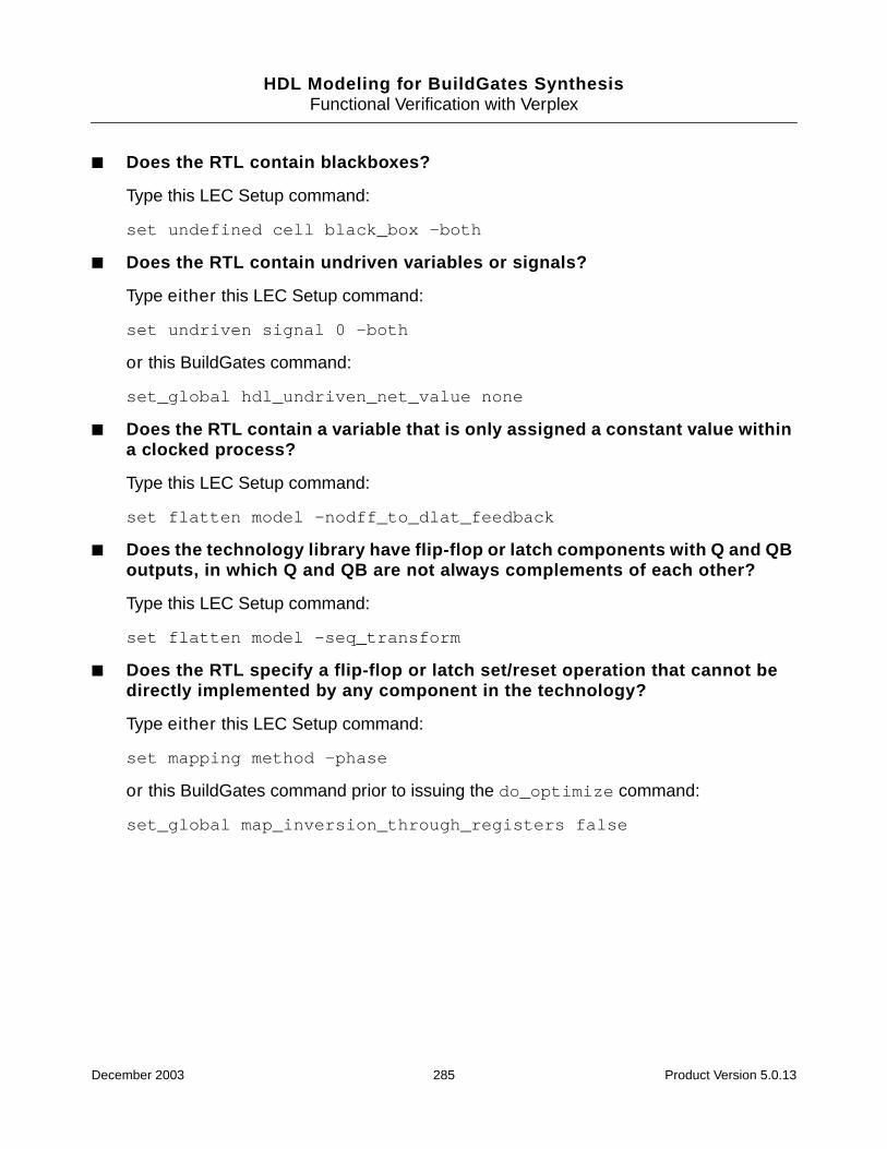
HDL Modeling for BuildGates SynthesisFunctional Verification with Verplex
■ Does the RTL contain blackboxes?
Type this LEC Setup command:
set undefined cell black_box -both
■ Does the RTL contain undriven variables or signals?
Type either this LEC Setup command:
set undriven signal 0 -both
or this BuildGates command:
set_global hdl_undriven_net_value none
■ Does the RTL contain a variable that is only assigned a constant value withina clocked process?
Type this LEC Setup command:
set flatten model -nodff_to_dlat_feedback
■ Does the technology library have flip-flop or latch components with Q and QBoutputs, in which Q and QB are not always complements of each other?
Type this LEC Setup command:
set flatten model -seq_transform
■ Does the RTL specify a flip-flop or latch set/reset operation that cannot bedirectly implemented by any component in the technology?
Type either this LEC Setup command:
set mapping method -phase
or this BuildGates command prior to issuing the do_optimize command:
set_global map_inversion_through_registers false
December 2003 285 Product Version 5.0.13
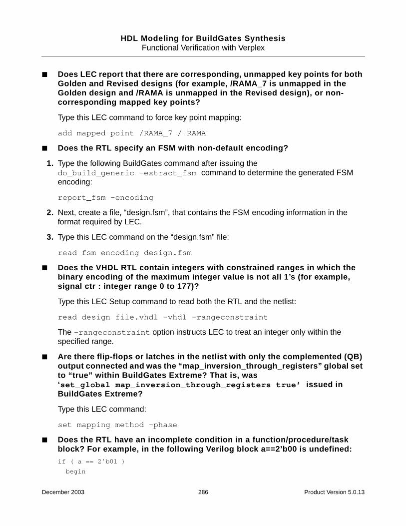
HDL Modeling for BuildGates SynthesisFunctional Verification with Verplex
■ Does LEC report that there are corresponding, unmapped key points for bothGolden and Revised designs (for example, /RAMA_7 is unmapped in theGolden design and /RAMA is unmapped in the Revised design), or non-corresponding mapped key points?
Type this LEC command to force key point mapping:
add mapped point /RAMA_7 / RAMA
■ Does the RTL specify an FSM with non-default encoding?
1. Type the following BuildGates command after issuing thedo_build_generic -extract_fsm command to determine the generated FSMencoding:
report_fsm -encoding
2. Next, create a file, “design.fsm”, that contains the FSM encoding information in theformat required by LEC.
3. Type this LEC command on the “design.fsm” file:
read fsm encoding design.fsm
■ Does the VHDL RTL contain integers with constrained ranges in which thebinary encoding of the maximum integer value is not all 1’s (for example,signal ctr : integer range 0 to 177)?
Type this LEC Setup command to read both the RTL and the netlist:
read design file.vhdl -vhdl -rangeconstraint
The -rangeconstraint option instructs LEC to treat an integer only within thespecified range.
■ Are there flip-flops or latches in the netlist with only the complemented (QB)output connected and was the “map_inversion_through_registers” global setto “true” within BuildGates Extreme? That is, was‘set_global map_inversion_through_registers true’ issued inBuildGates Extreme?
Type this LEC command:
set mapping method -phase
■ Does the RTL have an incomplete condition in a function/procedure/taskblock? For example, in the following Verilog block a==2’b00 is undefined:if ( a == 2’b01 )
begin
December 2003 286 Product Version 5.0.13

HDL Modeling for BuildGates SynthesisFunctional Verification with Verplex
out = b ;
end
else if ( a == 2’b10 )
begin
out = c ;
end
else if ( a == 2’b11 )
begin
out = d ;
end
BuildGates Extreme interprets this case as a dont care but LEC does not,which can lead to mismatches being reported.
To interpret this as a dont care in LEC, read in the design using the -functiondefaultX option:
read design test.v -functiondefault X -golden
December 2003 287 Product Version 5.0.13

HDL Modeling for BuildGates SynthesisFunctional Verification with Verplex
December 2003 288 Product Version 5.0.13

HDL Modeling for BuildGates Synthesis
Index
Aadder architectures 53, 92
select 272Ambit Database (ADB) 69AmbitWare
componentcontrol the architecture 280
flow 268generators 269
Arithmetic Component Library(AWACL) 266, 270
Datapath (AWDP) 266, 271Multiplexer (AWMUX) 266, 273Resource Shared Module
(AWRS) 266, 275Sum-of-Products (AWSOP) 266,
274libraries 70, 267, 276
Complex Arithmetic(AWARITH) 267
Complex Logical (AWLOGIC) 267create a report 281define 277delete or disable a component 279predefined 277Sequential Logic (AWSEQ) 267set search order 277use your own 279
architectureadder 53
change 270select 272
changeAmbitWare component 280
Datapath 176datapath 29define names 156entity restrictions 162error if not specified 214multiplier 273report 29selection 53
specify with multiple operators 93Verilog directive 92VHDL directive 176
with resource sharing 65VHDL entity 27, 154, 160write 156
areaimprove with THR 46minimize by matching bit widths 58
arithmeticcomponent library (AWACL) 28expression tree 46expressions
redundant 51sharing 58
logic unit (ALU) 24packages 149
arrayassign values 129definitions 205multidimensional 134slices 207
asynchronousset and reset pins
generating incorrect logic 125asynchronous operation
Verilog 80VHDL 168
ATLAmbit Technology Library 273cells 31, 73extended library (XATL) 28
attributesAmbit 145Boolean-valued 183, 186control FSM optimization 213predefined VHDL 206, 208preserve 30VHDL 174, 188VHDL FSM 245
Bbinary netlist database 25, 30bit-width matching 47blackbox
link 253block directives 102
December 2003 289 Product Version 5.0.13

HDL Modeling for BuildGates Synthesis
specify in Verilog 100Boolean
equations 31, 54gates 24
buildgeneric design
Verilog 72VHDL 155
busseseliminate in a netlist 118write a 1-bit bus as a signal 219
Ccarry-save inferences 65case statement 54
extract logic 54extract PLAs 275generate 131infer a latch
Verilog 83VHDL 171
infer a registerVHDL 170
multi-way branching in Verilog 83prevent a latch in VHDL 171Verilog synthesis directive 93VHDL synthesis directive 177
casex statementreport 87using dont care conditions 88Verilog 85
casez statementVerilog 85
cellsATL and XATL 31
cla (carry look ahead adder) 53, 92clock
async in Verilog 98edges
specifying in VHDL 169gating candidates 123signals
specifying in VHDL 169code compliance
verify with the LRM 147coding style
FSM 230combinational
logic
Verilog 76VHDL 164
loopsavoiding 62
Commandsdelete_aware_component
delete a component from anAmbitWare library 279
do_blast_busseseliminate busses 118remove bus objects 124
do_build_genericbuild generic design 28extract state transition table for a
FSM 225functions 28perform FSM extraction 56RTL synthesis flow 25transform Verilog design into
netlist 72transform VHDL design into a
netlist 155do_change_name
replace long module names 118do_optimize
optimize design 28RTL synthesis flow 25
get_hdl_filereturn the name of the HDL source
file 36get_hdl_hierarchy
display the design hierarchy 35get_hdl_top_level
list names of all top level designs 35get_hdl_type
get the language design is writtenin 36
read_adbexchange design data 27load data from .adb file into
database 30read_edif
exchange design data between CADsystems 27
import EDIF designs 253read_verilog 27
create a quick direct netlist fordesigns containing onlystructural constructs 71
read in design files 70read_vhdl 27
December 2003 290 Product Version 5.0.13
HDL Modeling for BuildGates Synthesis
analyze and store information into alibrary 149
report_aware_librarycreate a report of an AmbitWare
library 281report_fsm
view state transition table for aFSM 225
view valid states 238report_resources
generate reports 42view data about hardware
resources 29report_vhdl_library
show mapping between library anddirectory 149
reset_vhdl_libraryreset and remove VHDL units 150
set_aware_component_propertydisable a component 279
set_aware_librarycreate AmbitWare library 278
write_adbRTL synthesis flow 25save generic netlist for
optimization 30write_edif
write out designs in EDIFformat 254
write_verilogwrite netlist 74write out a Verilog netlist 74
write_vhdlwrite netlist 159
Common Sub-Expression Elimination(CSE) 51
compiler directivesFSM 213Verilog 104Verilog 2001 138
componentarithmetic 24, 28hardware 24instantiations 160Verilog 32VHDL 32
componentsVerilog 27VHDL 27
constantfunctions 137
constraintsVerilog and VHDL designs 32
constructsVerilog 108VHDL 199
csel (carry select adder) 53
DDatapath
architectures 92DP
supported constructs 108implement components 272
Datapath for BuildGates Synthesis andCadence PKS 92
declareports and parameters 136
default valueassign in next_state
Verilog 84VHDL 171
default valuesglobals 42override
for generics 38delay
reduce 46directives
Finite State Machine (FSM) 213parentheses in THR 48Verilog
compiler 104preprocessor 138Synopsys 105synthesis 90
VHDLBuildGates Synthesis 194Cadence (Ambit) and BuildGates
equivalents 193Synopsys 191synthesis 174
dont care conditionsFSM values 233modeling in Verilog 86
Eelaborate design 38
December 2003 291 Product Version 5.0.13
HDL Modeling for BuildGates Synthesis
Electronic Design Exchange Format(EDIF) 69, 261
import EDIF designs 253link blackboxes 253represent power and ground
instances 259nets 255ports 257when reading in EDIF designs 261when writing out EDIF 254
write netlist 254elsif directive 140entities
reusing 151VHDL 27
escape characterseliminating in front of signal names 120
extensionsVerilog-2001 127
Ffcla (fast carry look ahead adder) 53Finite State Machine (FSM)
check terminal state 227coding styles 230
avoid simulation mismatch 233compact 234detailed 235-reachable option 233set state and output values 233specific valid state for outputs 233
directivesVHDL state_vector 228
extract 56state transition table 225
minimizing state for two or moreequivalent states 227
set compile directives for a VHDL finitestate 213
state vector encoding styles 226structure 222verification 237
avoid RTL and netlistmismatches 241
avoid sequential optimizations 237code default clause with a restricted
structure 237state vector pragma 238unknown values in simulation
output 242use -reachable option for sequential
optimization 238using a simulator 239view valid states 238
view state transition table 225flip-flop
modeling in Verilog 79modeling in VHDL 166specifying clock edges in VHDL 169specifying clock signals in VHDL 169synthesizing asynchronous set and reset
VHDL 168unconnected in final netlist 212
floating nets 125for
generate statement 133statement
describe repetitive operationsVerilog 89VHDL 171
supported formsVerilog 89VHDL 173
full case 94functions and tasks
automatic 135mapping
Verilog 96VHDL 178
Ggenerate statements 129
case 129for 129if 129
generatorsAmbitWare 266
genericnetlist
generate from a RTL model 24simulate before optimization 31writing and saving 25
valuespassing from the command line 219
genvar 133Global (reset_global)
reset the value of a global to its defaultvalue 42
December 2003 292 Product Version 5.0.13
HDL Modeling for BuildGates Synthesis
Globals (set_global) 42aware_adder_architecture
set default adder architecture for finaladders 270
set default architecture 53aware_dissolve_width
set size of components that aredissolved 270
aware_implementation_selectionimplement datapath elements 272
aware_library_search_orderset order aware libraries search for
components 277aware_merge_operators
control operator merging 272aware_multiplier_architecture
set default for multipliers 273aware_mux_dissolve_size
reduce runtime by defining thresholdsize 55
set size of multiplexer to bedissolved 274
buscomp_generatoreliminate escape characters 120
dcn_module_max_lengthuse after do_build_generic to change
long module names 118edif out_ground_net_property_value
specify property value for groundnet 255
edifin_ground_instance_namespecify ground instance name 262
edifin_ground_net_namespecify name for ground net 261
edifin_ground_net_property_namespecify property name for ground
net 261edifin_ground_net_property_value
specify property value for groundnet 261
edifin_ground_pin_namespecify ground pin name 262
edifin_ground_port_namespecify ground port name 261
edifin_power_instance_namespecify power instance name 262
edifin_power_net_namespecify name for power net 261
edifin_power_net_property_namespecify property name for power
net 261
edifin_power_net_property_valuespecify property value for power
net 261edifin_power_pin_name
specify power pin name 261edifin_power_port_name
specify power net name 261edifout_ground_cell_name
specify name for ground cell 259edifout_ground_net_name
specify name for ground net 255edifout_ground_net_property_name
specify property name for groundnet 255
edifout_ground_pin_namespecify name for ground pin 259
edifout_ground_port_namespecify ground port name 257
edifout_power_and_ground_representation
represent power and ground inEDIF 255
edifout_power_cell_namespecify name of power cell 259
edifout_power_instance_namespecify name for power
instance 259edifout_power_net_name
specify power net name 255edifout_power_net_property_name
specify property name for powernet 255
edifout_power_net_property_valuespecify property value for power
net 255edifout_power_pin_name
specify power pin name 259edifout_power_port_name
specify power port name 257hdl_common_subexpression_eliminatio
nremove redundant expressions 51
hdl_extract_sum_of_products_logicextract logic from constant case
statements 275reduce area 54
hdl_resource_sharingreduce logic modules 45
hdl_tree_height_reductionminimize delay of complex arithmetic
expressions 46
December 2003 293 Product Version 5.0.13

HDL Modeling for BuildGates Synthesis
hdl_undriven_net_valueconnect undriven nets to specified
value 211create a floating net 125
hdl_verilog_out_columnsspecify line length 72
hdl_verilog_out_compactwrite out compact files for Verilog
netlist 72hdl_verilog_out_declare_implicit_wires
write declarations for implicitwires 73
hdl_verilog_out_primwrite primitive Verilog operators 73
hdl_verilog_out_source_trackkeep track of RTL source code 73
hdl_verilog_out_unconnected_styleselect netlisting style for unconnected
instance pins 73hdl_verilog_out_use_supply
specify constant signals as supplysignals 73
hdl_verilog_read_versionspecify mode of parsing and turn on
language-specific errorchecks 129
specify Verilog version 70hdl_verilog_vpp_arg
pass arguments to VerilogPreprocessor 71
hdl_vhdl_casespecify case of names 153
hdl_vhdl_environmentchange the VHDL environment 144
hdl_vhdl_lrm_complianceverify code compliance 147
hdl_vhdl_preferred_architecturespecify preferred architecture 154
hdl_vhdl_read_versionspecify version to read designs 151
hdl_vhdl_reuse_unitsimport previously analyzed
entities 151hdl_vhdl_write_architecture
write design entity 156hdl_vhdl_write_architecture_name
specify name of entityarchitecture 156
hdl_vhdl_write_bit_typedefine bit-level type used in
netlist 157
specify whether netlist containsstd_logic or std_ulogicports 219
hdl_vhdl_write_componentsspecify component declarations for
technology cells 159hdl_vhdl_write_entity
write out entities 157hdl_vhdl_write_entity_name
specify entity name 157hdl_vhdl_write_packages
specify library and use clauses thatprecede modules writtenout 158
hdl_vhdl_write_versionspecify version of netlist written
out 158hdl_write_top_down
specify how netlists are writtenout 156
write out Verilog modules in top-downor bottom-up order 74
naming_stylespecify object name style 153specify Verilog input and output
object names 70set_vhdl_library
define a logical library 148map WORK library 148
Hhierarchical
argument with report resources 29block names 100design order 27list of modules 106names 115references 108signal names 101VHDL designs 160
IIEEE
Language Reference Manual(LRM) 128
redefine library to a new directory 149referring to VHDL packages in
December 2003 294 Product Version 5.0.13

HDL Modeling for BuildGates Synthesis
netlists 158resolution function 205Standard logic packages
error 212Standard VHDL Language Reference
Manual 142vendor-specific packages 151VHDL libraries 144
ifgenerate statement 130statement
applying ICP 50modeling in Verilog 82negating the condition in Verilog 82
ifndef directive 139Implicit Constant Propagation (ICP) 50improve
design with high level optimizations 41optimization 227, 230slack and area 46
Llatch
inferVerilog 78VHDL 171
model a state transition tableVerilog 83VHDL 171
preventVerilog 84, 85VHDL 171
suppressVerilog 94
librariesAmbitWare 267ATL and XATL 273define
AmbitWare 277VHDL 148
delete a component 279map WORK 148predefined
AmbitWare 277common 146standard 145Synergy 145Synopsys 145VHDL 145
reset VHDL 150use your own 279
line directive 139
Mmeta-comment
VHDL 174minimize
FSM state 227modeling
arithmetic expressions for sharing 59asynchronous set and reset signals
VHDL 168bit-width matching 47clock edges for flip-flops
VHDL 169combinational logic
Verilog 76VHDL 164
dont care conditionsVerilog 86, 88
flip-flopVerilog 79VHDL 166
for statementVerilog 89VHDL 173
if statementVerilog 82VHDL 169
latch using an incomplete case statementVerilog 83VHDL 171
register as a flip-flopVerilog 79VHDL 166
register as a latchVerilog 78VHDL 165
set and reset control logicVerilog 99VHDL 182
state transition tableVerilog 83VHDL 171
synchronous set and reset signalsVerilog 101VHDL 168
Verilog styles 75
December 2003 295 Product Version 5.0.13
HDL Modeling for BuildGates Synthesis
supported constructs 108VHDL styles 163
supported constructs 199module
replace long names 118synthesize 36
multidimensional arrays 134multiple top-level designs 37multiplexer
ATL and XATL 273case directive 95optimization 55remove redundant 61set size 274
multiplier architecture 273
Nname
get HDL file names 153mapping
resolving with formalverification 118
modifying case 153replace long module names 118style of VHDL objects 153
netsfloating 125undriven
extra generic logic 211
Ooperator
mergingcontrolling 272directive 103with resource sharing 63
width limit 270, 271optimize
design 29
Pparallel case
Verilog synthesis directive 95parameter
override default values 40
passing by namedefparam statement 135redefinition 135
parenthesesuse with Tree Height Reduction 46
power and groundrepresent in EDIF 254
predefinedAmbitWare libraries 277attributes 245VHDL
attributes 206, 208Environments 144libraries 145
preserveinstances without directives 121set and reset signals 122
preventmodules from being overwritten during
read_verilog 122procedural assignments
Verilog 76VHDL 166
programmable logic arrays (PLAs)extract 275
propagateconstants 50values 38
Qquery
HDL design hierarchy 33
Rreachable option 233read
design data 27libraries 25Verilog design data 69VHDL design data 148
registerinfer
as a flip-flopVerilog 79VHDL 166
as a latchVerilog 78
December 2003 296 Product Version 5.0.13
HDL Modeling for BuildGates Synthesis
VHDL 165using case statements
VHDL 170prune with D inputs constant 120set and reset control 98
register inferencing 165remove
bus objects 124resource sharing 45
architecture selection 65avoiding combinational loops 62carry-save inferencing 65matching bit widths 60matching common HDL variables 60minimizing area 59minimizing MUX overhead 60nested conditions 61operator merging 63removing redundant multiplexers 61sharing across nested conditions 61sharing hardware resources 58sleep-mode operation 65
ripple adder 53RTL Synthesis
basic steps 24flow 25Tcl script 25
Ssave generic netlist 30set and reset
generating incorrect logic 125Verilog synthesis directive 98
signalcomma-separated list 136directives
Verilog 101simulate a generic netlist 31simulation
avoid mismatch 233slack
improve with resource sharing 46sleep-mode operation 65state transition table
extract and view for a FSM 225modeling in VHDL 171
state vectorencoding options 226
state_vector directive
VHDL 228Sum-of-Products (SOP)
generator 275logic 54
supportedadder architectures 53Verilog
modeling constructs 108VHDL
Ambit directives and BuildGatesEquivalents 193
BuildGates Synthesis-onlydirectives 194
environments 144libraries common 146libraries standard 145libraries Synergy environment 145libraries Synopsys 145modeling constructs 199Synopsys directives 191
Synergypredefined VHDL libraries 145
Synopsyspredefined VHDL libraries 145supported Verilog directives 105supported VHDL directives 191
synthesis directivesuse with AmbitWare library
components 282Verilog 90
architecture selection 92case statement 93full case 94function and task 96module template 96multiplexer 95parallel case 95set and reset 98synthesis on and off 91
VHDL 174architecture selection 176case statement 177code selection 175entity template 178enumeration encoding 177function and task mapping 178operator merging 190process 183resolution function 179set and reset 181signal directives 186
December 2003 297 Product Version 5.0.13
HDL Modeling for BuildGates Synthesis
signed type 179sync_reset_local 188synthesis on and off 175translate on and off 175type conversion directives 180
synthesizemixed VHDL and Verilog designs 32multiple top-level designs 37parameterized designs 38specified module 36VHDL designs 141
Ttasks
AmbitWare 268EDIF 252FSM 225high-level optimizations 44Verilog 69VHDL 143
tclforeach 37RTL synthesis script 25
template directiveVerilog module 96VHDL entity 178
terminal state check 227tree height reduction (THR) 46
Uunconditional loops
support 214
Vvalues
override 40propagate 38specify 40
variablepart select 137
vendor specific packages 149Verilog
1995 1292001 extensions 127compiler directives 104
DP 70, 129supported constructs 108
for statements 89get file names, hierarchy, and top-level
designs 71keep track of RTL source code 73modeling styles 75preprocessor (VPP) 71
directives 137, 138, 289honoring defines in an include
file 123passing arguments 71
read design data 69related commands and globals 106select netlist style for unconnected
pins 73specify
line length 72naming style 70supply signals 73version 70
store modules as components inAmbitWare library 70
supported modeling constructs 108Synopsys directives 105synthesis directives 90
architecture selection 92block directives 100case statement 93full case 94function and task mapping 96module template 96multiplexer case directive 95operator merging 103parallel case directive 95set and reset 98signal 101signals in a block directive 102synthesis on and off 91
Verilog-2001supported constructs 108
writecompact files 72declarations for implicit wires 73modules in top-down or bottom-up
order 74netlist 72, 74primitive operators 73
VHDLanalyze and store a file into a
library 149
December 2003 298 Product Version 5.0.13

HDL Modeling for BuildGates Synthesis
build generic design 155change the environment 144code state machines 245concurrent statements 208declarations 206define
architecture name 156logical libraries 148
design entities and configurations 204hierarchical designs 159
component instantiations andbindings 160
map WORK library 148modeling styles 163names 206predefined
attributes 208common environment 146environments 144libraries
standard environment 145Synergy libraries 145Synopsys environment 145
read design data 148related commands and globals 196reset library 150restrictions on entities with multiple
architectures 162reuse previously analyzed entities 151select
bit-level type 157preferred architectures 154
sequential statements 207show mapping between libraries and
directory 149specify
case of names 153entity name 157library and use clauses that precede
modules written out 158object naming style 153version 158
subprograms and packages 205supported
Ambit and BuildGatesequivalents 193
constructs 199Synopsys directives 191synthesis-only directives 194
switch between versions 151synthesis directive
function and task mapping 178synthesis directives 174
architecture selection 176case statement 177code selection 175entity template 178enumeration encoding 177operator merging 190process 183resolution function 179set and reset 181signal 186signed type 179synthesis on and off 175translate on and off 175type conversion 180
types 205using arithmetic packages from
vendors 149verify code compliance 147write
architectures 156component declarations 159entities 157netlist 159out modules in top-down or bottom-up
order 156
Wwait
error on condition clause 215WORK library 148write
architectures 156final netlist 25generic netlist 25, 29, 204Verilog netlist 72VHDL
architectures 156component declarations 159entities 157modules in top-down or bottom-up
order 156netlist 156, 159
XXATL
December 2003 299 Product Version 5.0.13

HDL Modeling for BuildGates Synthesis
Extended Amit Technology Library 273XATL cells 31
December 2003 300 Product Version 5.0.13