Embed Size (px)
Citation preview
Timing Analysis for Ambit ® BuildGates ®
Synthesis and Cadence ® PKS
Product Version 4.0.8May, 2001

1999-2001 Cadence Design Systems, Inc. All rights reserved.Printed in the United States of America.
Cadence Design Systems, Inc., 555 River Oaks Parkway, San Jose, CA 95134, USA
Trademarks: Trademarks and service marks of Cadence Design Systems, Inc. (Cadence) contained in thisdocument are attributed to Cadence with the appropriate symbol. For queries regarding Cadence’s trademarks,contact the corporate legal department at the address shown above or call 1-800-862-4522.
All other trademarks are the property of their respective holders.
Restricted Print Permission: This publication is protected by copyright and any unauthorized use of thispublication may violate copyright, trademark, and other laws. Except as specified in this permission statement,this publication may not be copied, reproduced, modified, published, uploaded, posted, transmitted, ordistributed in any way, without prior written permission from Cadence. This statement grants you permission toprint one (1) hard copy of this publication subject to the following conditions:
1. The publication may be used solely for personal, informational, and noncommercial purposes;2. The publication may not be modified in any way;3. Any copy of the publication or portion thereof must include all original copyright, trademark, and other
proprietary notices and this permission statement; and4. Cadence reserves the right to revoke this authorization at any time, and any such use shall be
discontinued immediately upon written notice from Cadence.
Disclaimer: Information in this publication is subject to change without notice and does not represent acommitment on the part of Cadence. The information contained herein is the proprietary and confidentialinformation of Cadence or its licensors, and is supplied subject to, and may be used only by Cadence’s customerin accordance with, a written agreement between Cadence and its customer. Except as may be explicitly setforth in such agreement, Cadence does not make, and expressly disclaims, any representations or warrantiesas to the completeness, accuracy or usefulness of the information contained in this document. Cadence doesnot warrant that use of such information will not infringe any third party rights, nor does Cadence assume anyliability for damages or costs of any kind that may result from use of such information.
Restricted Rights: Use, duplication, or disclosure by the Government is subject to restrictions as set forth inFAR52.227-14 and DFAR252.227-7013 et seq. or its successor.
Timing Analysis for Ambit BuildGates Synthesis and Cadence PKS
Contents
Preface .......................................................................................................................... 11
About This Manual . . . . . . . . . . . . . . . . . . . . . . . . . . . . . . . . . . . . . . . . . . . . . . . . . . . . . . 11Other Information Sources . . . . . . . . . . . . . . . . . . . . . . . . . . . . . . . . . . . . . . . . . . . . . . . . 11Syntax Conventions . . . . . . . . . . . . . . . . . . . . . . . . . . . . . . . . . . . . . . . . . . . . . . . . . . . . . 12
Text Command Syntax . . . . . . . . . . . . . . . . . . . . . . . . . . . . . . . . . . . . . . . . . . . . . . . . 12About the Graphical User Interface . . . . . . . . . . . . . . . . . . . . . . . . . . . . . . . . . . . . . . . . . 13
Using Menus . . . . . . . . . . . . . . . . . . . . . . . . . . . . . . . . . . . . . . . . . . . . . . . . . . . . . . . 13Using Forms . . . . . . . . . . . . . . . . . . . . . . . . . . . . . . . . . . . . . . . . . . . . . . . . . . . . . . . . 14
1Introduction . . . . . . . . . . . . . . . . . . . . . . . . . . . . . . . . . . . . . . . . . . . . . . . . . . . . . . . . 15
Static Timing Analysis . . . . . . . . . . . . . . . . . . . . . . . . . . . . . . . . . . . . . . . . . . . . . . . . . . . 16Features . . . . . . . . . . . . . . . . . . . . . . . . . . . . . . . . . . . . . . . . . . . . . . . . . . . . . . . . . . . 16Supported File Formats . . . . . . . . . . . . . . . . . . . . . . . . . . . . . . . . . . . . . . . . . . . . . . . 17
Timing Analysis in the Synthesis Flow . . . . . . . . . . . . . . . . . . . . . . . . . . . . . . . . . . . . . . . 19Timing in the Generic Synthesis Flow . . . . . . . . . . . . . . . . . . . . . . . . . . . . . . . . . . . . 19Timing in the PKS Flow . . . . . . . . . . . . . . . . . . . . . . . . . . . . . . . . . . . . . . . . . . . . . . . 19
2Choosing a Methodology . . . . . . . . . . . . . . . . . . . . . . . . . . . . . . . . . . . . . . . . 21
Overview . . . . . . . . . . . . . . . . . . . . . . . . . . . . . . . . . . . . . . . . . . . . . . . . . . . . . . . . . . . . . 22Partitioning a Design . . . . . . . . . . . . . . . . . . . . . . . . . . . . . . . . . . . . . . . . . . . . . . . . . . . . 22Hierarchical Top-Down Methodology . . . . . . . . . . . . . . . . . . . . . . . . . . . . . . . . . . . . . . . . 22Bottom-Up Methodology . . . . . . . . . . . . . . . . . . . . . . . . . . . . . . . . . . . . . . . . . . . . . . . . . 23Bottom-Up-Top-Down Methodology . . . . . . . . . . . . . . . . . . . . . . . . . . . . . . . . . . . . . . . . . 23
Budgeting the Design . . . . . . . . . . . . . . . . . . . . . . . . . . . . . . . . . . . . . . . . . . . . . . . . . 23Serial and Parallel Bottom-Up-Top-Down . . . . . . . . . . . . . . . . . . . . . . . . . . . . . . . . . . 24
May, 2001 3 Product Version 4.0.8
Timing Analysis for Ambit BuildGates Synthesis and Cadence PKS
Annotating Physical Information . . . . . . . . . . . . . . . . . . . . . . . . . . . . . . . . . . . . . . . . . . . 25Floorplanners . . . . . . . . . . . . . . . . . . . . . . . . . . . . . . . . . . . . . . . . . . . . . . . . . . . . . . . 25Place and Route . . . . . . . . . . . . . . . . . . . . . . . . . . . . . . . . . . . . . . . . . . . . . . . . . . . . . 25In-Place Optimization . . . . . . . . . . . . . . . . . . . . . . . . . . . . . . . . . . . . . . . . . . . . . . . . . 25
Making Instances Unique . . . . . . . . . . . . . . . . . . . . . . . . . . . . . . . . . . . . . . . . . . . . . . . . 26Using TLF 4.3 — Delay and Slew Threshold Changes . . . . . . . . . . . . . . . . . . . . . . . . . . 27
Understanding Thresholds . . . . . . . . . . . . . . . . . . . . . . . . . . . . . . . . . . . . . . . . . . . . . 30
3Using Timing Libraries . . . . . . . . . . . . . . . . . . . . . . . . . . . . . . . . . . . . . . . . . . . 33
Reading Timing Libraries . . . . . . . . . . . . . . . . . . . . . . . . . . . . . . . . . . . . . . . . . . . . . . . . . 34Using Cadence TLF Libraries . . . . . . . . . . . . . . . . . . . . . . . . . . . . . . . . . . . . . . . . . . . 36Using Synopsys .lib Libraries . . . . . . . . . . . . . . . . . . . . . . . . . . . . . . . . . . . . . . . . . . . 43Using Synopsys Stamp Models . . . . . . . . . . . . . . . . . . . . . . . . . . . . . . . . . . . . . . . . . 51Using IEEE 1481 Delay and Power Calculation System (DCL) Libraries . . . . . . . . . . 54Using OLA v1.0.2 Libraries . . . . . . . . . . . . . . . . . . . . . . . . . . . . . . . . . . . . . . . . . . . . 60
Specifying Target Technology Libraries . . . . . . . . . . . . . . . . . . . . . . . . . . . . . . . . . . . . . . 62Multiple Target Libraries . . . . . . . . . . . . . . . . . . . . . . . . . . . . . . . . . . . . . . . . . . . . . . . 62
Linking Cells to a Target Technology Library . . . . . . . . . . . . . . . . . . . . . . . . . . . . . . . . . . 63Getting Library Information . . . . . . . . . . . . . . . . . . . . . . . . . . . . . . . . . . . . . . . . . . . . . . . 64Overriding Default Values in the Library . . . . . . . . . . . . . . . . . . . . . . . . . . . . . . . . . . . . . 65Updating Libraries . . . . . . . . . . . . . . . . . . . . . . . . . . . . . . . . . . . . . . . . . . . . . . . . . . . . . . 66
4Setting Timing Constraints . . . . . . . . . . . . . . . . . . . . . . . . . . . . . . . . . . . . . . 69
Timing Constraints Quick Reference . . . . . . . . . . . . . . . . . . . . . . . . . . . . . . . . . . . . . . . . 70Setting the Timing Context . . . . . . . . . . . . . . . . . . . . . . . . . . . . . . . . . . . . . . . . . . . . . . . . 72Specifying Clocks . . . . . . . . . . . . . . . . . . . . . . . . . . . . . . . . . . . . . . . . . . . . . . . . . . . . . . . 72
Defining Ideal Clocks . . . . . . . . . . . . . . . . . . . . . . . . . . . . . . . . . . . . . . . . . . . . . . . . . 74Defining Multiple Clock Domains . . . . . . . . . . . . . . . . . . . . . . . . . . . . . . . . . . . . . . . . 75Associating Clock Waveforms and Polarity to Pins . . . . . . . . . . . . . . . . . . . . . . . . . . 75Specifying Clock Insertion Delay . . . . . . . . . . . . . . . . . . . . . . . . . . . . . . . . . . . . . . . . 76Specifying Clock Uncertainty . . . . . . . . . . . . . . . . . . . . . . . . . . . . . . . . . . . . . . . . . . . 79Using Gated Clocks . . . . . . . . . . . . . . . . . . . . . . . . . . . . . . . . . . . . . . . . . . . . . . . . . . 82Using Derived Clocks . . . . . . . . . . . . . . . . . . . . . . . . . . . . . . . . . . . . . . . . . . . . . . . . . 87
May, 2001 4 Product Version 4.0.8
Timing Analysis for Ambit BuildGates Synthesis and Cadence PKS
Specifying Operating Conditions . . . . . . . . . . . . . . . . . . . . . . . . . . . . . . . . . . . . . . . . . . . 89Specifying Wire Loads . . . . . . . . . . . . . . . . . . . . . . . . . . . . . . . . . . . . . . . . . . . . . . . . . . . 89Specifying Boundary Conditions . . . . . . . . . . . . . . . . . . . . . . . . . . . . . . . . . . . . . . . . . . . 93Specifying Slew Rates . . . . . . . . . . . . . . . . . . . . . . . . . . . . . . . . . . . . . . . . . . . . . . . . . . . 93Specifying Design Rule Limits . . . . . . . . . . . . . . . . . . . . . . . . . . . . . . . . . . . . . . . . . . . . . 96Specifying Latch Transparency . . . . . . . . . . . . . . . . . . . . . . . . . . . . . . . . . . . . . . . . . . . . 97
Latch Transparency Examples . . . . . . . . . . . . . . . . . . . . . . . . . . . . . . . . . . . . . . . . . . 97
5Linking Physical Design Information . . . . . . . . . . . . . . . . . . . . . . . . . . 101
Exchanging Physical Design Data . . . . . . . . . . . . . . . . . . . . . . . . . . . . . . . . . . . . . . . . . 102Forward Annotation . . . . . . . . . . . . . . . . . . . . . . . . . . . . . . . . . . . . . . . . . . . . . . . . . 102Backannotation . . . . . . . . . . . . . . . . . . . . . . . . . . . . . . . . . . . . . . . . . . . . . . . . . . . . . 102
The Generic Synthesis and Timing Task Flow . . . . . . . . . . . . . . . . . . . . . . . . . . . . . . . . 103Integrate Chip-Level Timing . . . . . . . . . . . . . . . . . . . . . . . . . . . . . . . . . . . . . . . . . . . 105Verify Chip-level Timing . . . . . . . . . . . . . . . . . . . . . . . . . . . . . . . . . . . . . . . . . . . . . . 105Initial Floorplanning . . . . . . . . . . . . . . . . . . . . . . . . . . . . . . . . . . . . . . . . . . . . . . . . . 105Final Floorplanning and Placement . . . . . . . . . . . . . . . . . . . . . . . . . . . . . . . . . . . . . 105Post Placement Timing Analysis . . . . . . . . . . . . . . . . . . . . . . . . . . . . . . . . . . . . . . . 106Post Final Route Timing Analysis . . . . . . . . . . . . . . . . . . . . . . . . . . . . . . . . . . . . . . . 106
Generating SDF Constraint Files . . . . . . . . . . . . . . . . . . . . . . . . . . . . . . . . . . . . . . . . . . 107Sample SDF Constraint File . . . . . . . . . . . . . . . . . . . . . . . . . . . . . . . . . . . . . . . . . . . 107
Backannotation Support . . . . . . . . . . . . . . . . . . . . . . . . . . . . . . . . . . . . . . . . . . . . . . . . 108Reading SDF Files . . . . . . . . . . . . . . . . . . . . . . . . . . . . . . . . . . . . . . . . . . . . . . . . . . . . . 109
Finding Missing SDF Annotations . . . . . . . . . . . . . . . . . . . . . . . . . . . . . . . . . . . . . . 109Reading Net Parasitic Files . . . . . . . . . . . . . . . . . . . . . . . . . . . . . . . . . . . . . . . . . . . . . . 109
Sample Net Parasitic File . . . . . . . . . . . . . . . . . . . . . . . . . . . . . . . . . . . . . . . . . . . . . 109Finding Missing Net Parasitic Annotations . . . . . . . . . . . . . . . . . . . . . . . . . . . . . . . . 110
May, 2001 5 Product Version 4.0.8
Timing Analysis for Ambit BuildGates Synthesis and Cadence PKS
Reading SPF and SPEF Files . . . . . . . . . . . . . . . . . . . . . . . . . . . . . . . . . . . . . . . . . . . . 110The Recommended IPO Approach . . . . . . . . . . . . . . . . . . . . . . . . . . . . . . . . . . . . . . . . 111Physical Design Exchange Format (PDEF) Flow . . . . . . . . . . . . . . . . . . . . . . . . . . . . . 112
6Deriving the Timing Context for a Module . . . . . . . . . . . . . . . . . . . . 115
Timing Context of a Module . . . . . . . . . . . . . . . . . . . . . . . . . . . . . . . . . . . . . . . . . . . . . . 116Using Time-Budgeting to Derive a Module’s Timing Context . . . . . . . . . . . . . . . . . . . . . 117
Using the dont_modify and do_uniquely_instantiate Commands . . . . . . . . . . . . . . 117Deriving the Timing Context in Synthesis . . . . . . . . . . . . . . . . . . . . . . . . . . . . . . . . . 118Using do_derive_context with Backannotated Timing and RC Information . . . . . . . 122
7Generating and Understanding Timing Reports . . . . . . . . . . . . . 127
Types of Reports for Timing . . . . . . . . . . . . . . . . . . . . . . . . . . . . . . . . . . . . . . . . . . . . . . 128Checking the Design for Timing Problems . . . . . . . . . . . . . . . . . . . . . . . . . . . . . . . . . . . 128Generating Library Reports . . . . . . . . . . . . . . . . . . . . . . . . . . . . . . . . . . . . . . . . . . . . . . 129Generating Timing Reports . . . . . . . . . . . . . . . . . . . . . . . . . . . . . . . . . . . . . . . . . . . . . . 129Generating Design Information Reports . . . . . . . . . . . . . . . . . . . . . . . . . . . . . . . . . . . . 130
Generating Clock Reports . . . . . . . . . . . . . . . . . . . . . . . . . . . . . . . . . . . . . . . . . . . . 130Generating Port Reports . . . . . . . . . . . . . . . . . . . . . . . . . . . . . . . . . . . . . . . . . . . . . 132Generating Cell Reports . . . . . . . . . . . . . . . . . . . . . . . . . . . . . . . . . . . . . . . . . . . . . . 133Generating Net and Pin Reports . . . . . . . . . . . . . . . . . . . . . . . . . . . . . . . . . . . . . . . 134
Generating Path Exception Reports . . . . . . . . . . . . . . . . . . . . . . . . . . . . . . . . . . . . . . . 136Understanding Reports . . . . . . . . . . . . . . . . . . . . . . . . . . . . . . . . . . . . . . . . . . . . . . . . . 137
Phase Shift in Single Clock Domains . . . . . . . . . . . . . . . . . . . . . . . . . . . . . . . . . . . . 137Phase Shift in Multiple Clock Domains . . . . . . . . . . . . . . . . . . . . . . . . . . . . . . . . . . . 137Loop Check and Time Borrowed . . . . . . . . . . . . . . . . . . . . . . . . . . . . . . . . . . . . . . . 139
May, 2001 6 Product Version 4.0.8
Timing Analysis for Ambit BuildGates Synthesis and Cadence PKS
8Identifying and Eliminating False Paths . . . . . . . . . . . . . . . . . . . . . . . 141
Critical False Path Verification Overview . . . . . . . . . . . . . . . . . . . . . . . . . . . . . . . . . . . . 142Static and Robust False Paths . . . . . . . . . . . . . . . . . . . . . . . . . . . . . . . . . . . . . . . . . . . . 142Reporting and Eliminating False Paths . . . . . . . . . . . . . . . . . . . . . . . . . . . . . . . . . . . . . 149
CFPV Use Model . . . . . . . . . . . . . . . . . . . . . . . . . . . . . . . . . . . . . . . . . . . . . . . . . . . 150Options to report_timing for False Path Analysis . . . . . . . . . . . . . . . . . . . . . . . . . . . 151
Example: Timing Reports with False Path Analysis . . . . . . . . . . . . . . . . . . . . . . . . . . . . 152
9Finding and Fixing Violations. . . . . . . . . . . . . . . . . . . . . . . . . . . . . . . . . . . 185
Finding Violations . . . . . . . . . . . . . . . . . . . . . . . . . . . . . . . . . . . . . . . . . . . . . . . . . . . . . 186Setting Path Exceptions . . . . . . . . . . . . . . . . . . . . . . . . . . . . . . . . . . . . . . . . . . . . . . . . . 186
Specifying False Paths . . . . . . . . . . . . . . . . . . . . . . . . . . . . . . . . . . . . . . . . . . . . . . . 186Specifying Path Delay Constraints . . . . . . . . . . . . . . . . . . . . . . . . . . . . . . . . . . . . . . 186Adding Cycles . . . . . . . . . . . . . . . . . . . . . . . . . . . . . . . . . . . . . . . . . . . . . . . . . . . . . 188Path Exception Priorities . . . . . . . . . . . . . . . . . . . . . . . . . . . . . . . . . . . . . . . . . . . . . 188Reporting Path Exceptions . . . . . . . . . . . . . . . . . . . . . . . . . . . . . . . . . . . . . . . . . . . . 189Specifying Constant Values . . . . . . . . . . . . . . . . . . . . . . . . . . . . . . . . . . . . . . . . . . . 189
10Using Advanced Analysis Techniques . . . . . . . . . . . . . . . . . . . . . . . . 193
Using RAM and ROM Models . . . . . . . . . . . . . . . . . . . . . . . . . . . . . . . . . . . . . . . . . . . . 194Using RAM and ROM Models In Logic Optimization . . . . . . . . . . . . . . . . . . . . . . . . 194Importing RAM and ROM Models Into Synthesis . . . . . . . . . . . . . . . . . . . . . . . . . . . 195A Simple RAM Cell Script . . . . . . . . . . . . . . . . . . . . . . . . . . . . . . . . . . . . . . . . . . . . . 195
Analyzing Latch-based Designs . . . . . . . . . . . . . . . . . . . . . . . . . . . . . . . . . . . . . . . . . . 200Latch Time Borrowing . . . . . . . . . . . . . . . . . . . . . . . . . . . . . . . . . . . . . . . . . . . . . . . 200Example 1. Balancing Slacks (No External Delay) . . . . . . . . . . . . . . . . . . . . . . . . . . 203Example 2. Balancing Slacks (External Delay) . . . . . . . . . . . . . . . . . . . . . . . . . . . . 208Limiting Time Borrowing . . . . . . . . . . . . . . . . . . . . . . . . . . . . . . . . . . . . . . . . . . . . . . 210
On and Off Chip Variation Analysis . . . . . . . . . . . . . . . . . . . . . . . . . . . . . . . . . . . . . . . . 212Analyzing Simultaneous Best Case and Worst Case On-Chip Variation . . . . . . . . . 212Analyzing Simultaneous Best Case and Worst Case Off-Chip Variation . . . . . . . . . 214
May, 2001 7 Product Version 4.0.8
Timing Analysis for Ambit BuildGates Synthesis and Cadence PKS
Common Path Pessimism Removal . . . . . . . . . . . . . . . . . . . . . . . . . . . . . . . . . . . . . . . . 216Common Path Pessimism Removal Command . . . . . . . . . . . . . . . . . . . . . . . . . . . . 217CPPR Script Example . . . . . . . . . . . . . . . . . . . . . . . . . . . . . . . . . . . . . . . . . . . . . . . 218Timing Analysis Results . . . . . . . . . . . . . . . . . . . . . . . . . . . . . . . . . . . . . . . . . . . . . . 219
ASample Tcl Scripts. . . . . . . . . . . . . . . . . . . . . . . . . . . . . . . . . . . . . . . . . . . . . . . 221
Converting Synopsys Scripts . . . . . . . . . . . . . . . . . . . . . . . . . . . . . . . . . . . . . . . . . . . . . 222Modular Scripts . . . . . . . . . . . . . . . . . . . . . . . . . . . . . . . . . . . . . . . . . . . . . . . . . . . . . . . 222Setting up the Synthesis Environment . . . . . . . . . . . . . . . . . . . . . . . . . . . . . . . . . . . . . . 223Reading Files . . . . . . . . . . . . . . . . . . . . . . . . . . . . . . . . . . . . . . . . . . . . . . . . . . . . . . . . . 224
A Script Showing How to Read Verilog Files . . . . . . . . . . . . . . . . . . . . . . . . . . . . . . 224Clocking and Default Constraints . . . . . . . . . . . . . . . . . . . . . . . . . . . . . . . . . . . . . . . . . . 224Applying Time Budget Constraints . . . . . . . . . . . . . . . . . . . . . . . . . . . . . . . . . . . . . . . . 225Design Rule Constraints . . . . . . . . . . . . . . . . . . . . . . . . . . . . . . . . . . . . . . . . . . . . . . . . 226
max_transition . . . . . . . . . . . . . . . . . . . . . . . . . . . . . . . . . . . . . . . . . . . . . . . . . . . . . 226max_capacitance . . . . . . . . . . . . . . . . . . . . . . . . . . . . . . . . . . . . . . . . . . . . . . . . . . . 227max_fanout . . . . . . . . . . . . . . . . . . . . . . . . . . . . . . . . . . . . . . . . . . . . . . . . . . . . . . . . 227
Optimization . . . . . . . . . . . . . . . . . . . . . . . . . . . . . . . . . . . . . . . . . . . . . . . . . . . . . . . . . . 227Writing Files . . . . . . . . . . . . . . . . . . . . . . . . . . . . . . . . . . . . . . . . . . . . . . . . . . . . . . . . . . 228Writing Reports . . . . . . . . . . . . . . . . . . . . . . . . . . . . . . . . . . . . . . . . . . . . . . . . . . . . . . . 228
BGenerating GCF Files . . . . . . . . . . . . . . . . . . . . . . . . . . . . . . . . . . . . . . . . . . . 229
Generating GCF 1.4 . . . . . . . . . . . . . . . . . . . . . . . . . . . . . . . . . . . . . . . . . . . . . . . . . . . 230Example . . . . . . . . . . . . . . . . . . . . . . . . . . . . . . . . . . . . . . . . . . . . . . . . . . . . . . . . . . . . . 236
CUnderstanding Errors and Warnings . . . . . . . . . . . . . . . . . . . . . . . . . . 243
Error Messages . . . . . . . . . . . . . . . . . . . . . . . . . . . . . . . . . . . . . . . . . . . . . . . . . . . . . . . 244Constraint Error Messages . . . . . . . . . . . . . . . . . . . . . . . . . . . . . . . . . . . . . . . . . . . . 244False Path Analysis Error Messages . . . . . . . . . . . . . . . . . . . . . . . . . . . . . . . . . . . . 244
May, 2001 8 Product Version 4.0.8

Timing Analysis for Ambit BuildGates Synthesis and Cadence PKS
Index.............................................................................................................................. 247
May, 2001 9 Product Version 4.0.8

Timing Analysis for Ambit BuildGates Synthesis and Cadence PKS
May, 2001 10 Product Version 4.0.8
Timing Analysis for Ambit BuildGates Synthesis and Cadence PKS
Preface
This preface contains the following sections:
■ About This Manual on page 11
■ Other Information Sources on page 11
■ Syntax Conventions on page 12
■ About the Graphical User Interface on page 13
About This Manual
This manual describes timing analysis within Ambit® BuildGates® synthesis and Cadence®
physically knowledgeable synthesis (PKS). To use this manual, you should be familiar withbasic timing analysis concepts and synthesis techniques.
Other Information Sources
For more information about Ambit BuildGates synthesis synthesis and other related products,you can consult the sources listed here.
■ Command Reference for Ambit BuildGates Synthesis and Cadence PKS
■ Test Synthesis for Ambit BuildGates Synthesis and Cadence PKS
■ HDL Modeling for Ambit BuildGates Synthesis
■ Distributed Processing of Ambit BuildGates Synthesis
■ Constraint Translator for Ambit BuildGates Synthesis and Cadence PKS
Depending on the product licenses your site has purchased, you could also have thesedocuments.
■ PKS User Guide
■ Datapath Option of Ambit BuildGates Synthesis and Cadence PKS
■ Low Power Option of Ambit BuildGates Synthesis and Cadence PKS
May, 2001 11 Product Version 4.0.8
Timing Analysis for Ambit BuildGates Synthesis and Cadence PKSPreface
Ambit BuildGates synthesis is often used with other Cadence® tools during various designflows. The following documents provide information about these tools and flows. Availabilityof these documents depends on the product licenses your site has purchased.
■ Cadence Timing Library Format Reference
■ Cadence Pearl Timing Analyzer User Guide
■ Cadence General Constraint Format Reference
The following books are helpful references.
■ IEEE 1364 Verilog HDL LRM
■ TCL Reference, Tcl and the Tk Toolkit, John K. Ousterhout, Addison-WesleyPublishing Company
Syntax Conventions
This section provides the Text Command Syntax used in this document.
Text Command Syntax
The list below describes the syntax conventions used for the Ambit BuildGates synthesis textinterface commands.
Important
Command names and arguments are case sensitive. User-defined information iscase sensitive for Verilog designs and, depending on the value specified for theglobal variable hdl_vhdl_case , may be case sensitive as well.
literal Nonitalic words indicate keywords that you must enter literally.These keywords represent command or option names.
argument Words in italics indicate user-defined arguments or informationfor which you must substitute a name or a value.
| Vertical bars (OR-bars) separate possible choices for a singleargument.
[ ] Brackets denote optional arguments. When used with OR-bars,they enclose a list of choices from which you can choose one.
May, 2001 12 Product Version 4.0.8
Timing Analysis for Ambit BuildGates Synthesis and Cadence PKSPreface
{ } Braces are used to indicate that a choice is required from the listof arguments separated by OR-bars. You must choose one fromthe list.
{ argument1 | argument2 | argument3 }
{ } Bold braces are used in Tcl commands to indicate that thebraces must be typed in literally.
... Three dots (...) indicate that you can repeat the previousargument. If the three dots are used with brackets (that is,[argument ]...) , you can specify zero or more arguments. Ifthe three dots are used without brackets (argument ...) , youmust specify at least one argument, but can specify more.
# The pound sign precedes comments in command files.
About the Graphical User Interface
This section describes the conventions used for the Ambit synthesis graphical user interface(GUI) commands and describes how to use the menus and forms in the Ambit synthesissoftware.
Using Menus
The GUI commands are located on menus at the top of the window. They can take one ofthree forms.
CommandName A command name with no dots or arrow executes immediately.
CommandName… A command name with three dots displays a form for choosingoptions.
CommandName -> A command name with a right arrow displays an additional menuwith more commands. Multiple layers of menus and commandsare presented in what are called command sequences, forexample: File – Import – LEF. In this example, you go to the Filemenu, then the Import submenu, and, finally, the LEF command.
May, 2001 13 Product Version 4.0.8
Timing Analysis for Ambit BuildGates Synthesis and Cadence PKSPreface
Using Forms
… A menu button that contains only three dots provides browsingcapability. When you select the browse button, a list of choicesappears.
Ok The Ok button executes the command and closes the form.
Cancel The Cancel button cancels the command and closes the form.
Defaults The Defaults button displays default values for options on theform.
Apply The Apply button executes the command but does not close theform.
Help The Help button provides information about the command.
May, 2001 14 Product Version 4.0.8
Timing Analysis for Ambit BuildGates Synthesis and Cadence PKS
1Introduction
This chapter introduces Cadence® timing analysis as used in the Ambit® BuildGates®
synthesis flow and the Cadence® physically knowledgeable synthesis (PKS) flow. Thefollowing topics are discussed:
■ Static Timing Analysis on page 16
❑ Features on page 16
❑ Supported File Formats on page 17
■ Timing Analysis in the Synthesis Flow on page 19
May, 2001 15 Product Version 4.0.8
Timing Analysis for Ambit BuildGates Synthesis and Cadence PKSIntroduction
Static Timing Analysis
Cadence timing analysis uses a signoff-quality, fast, full-chip timing engine that enables high-capacity and high-performance chip-level analysis. Timing analysis can be done on a widevariety of design styles such as multiple clock designs including both edge triggered and levelsensitive latches with cycle stealing.
Features
The basic features are outlined below. For information about features that are new for thisrelease, see the timing section in the Ambit BuildGates Synthesis Product Notes.
Interactive or Batch Mode
You can use timing analysis interactively from either the UNIX command line or the graphicaluser interface (GUI). This manual describes command line usage. The synthesis tools areinvoked by the ac_shell command. For information about starting ac_shell in either GUIor non-GUI mode, see “Getting Started” in the Ambit BuildGates Synthesis User Guide.
Timing analysis can also be done in batch mode using Tcl scripts. More detail about scriptsis provided in Appendix A, “Sample Tcl Scripts.”
Hierarchical or Flat Netlists
Some static timing analyzers require a flat netlist. Cadence timing analysis can use either flator hierarchical netlists. A context-based optimization approach is used for hierarchicalnetlists. The context is the set of constraints set at the top level of the design. Theseconstraints are pushed down the hierarchy so that each of the lower level modules areoptimized using the correct set of constraints. Later, as the higher level modules are groupedtogether, the optimized modules are all connected correctly with respect to each other.However, because logic across the hierarchy boundaries cannot be combined orrestructured, flattening the hierarchy can produce better results.
Time Budgeting
Time budgeting lets you start with initial time budget values rather than constraints derivedfrom context. This means fewer synthesis iterations and quicker convergence to targetperformance.
May, 2001 16 Product Version 4.0.8
Timing Analysis for Ambit BuildGates Synthesis and Cadence PKSIntroduction
Incremental Analysis
If the design has been synthesized once, the quality of design can be improved using anincremental optimization approach. In this process, portions of the design (clock net, forexample) can be extracted from the netlist and certain transformations applied for specificimprovements. For an incremental optimization, timing analysis re-times only the individualgates affected. A demand-driven algorithm performs only necessary updates rather than re-timing the whole design.
Supported File Formats
Cadence timing analysis supports most of the industry-standard file formats for exchangingtiming information that are in use today.
Input Files
Cadence timing analysis reads the following types of input files.
■ Timing Library Formats
❑ Synopsys™ Liberty (.lib)
❑ Synopsys™ Stamp Models
❑ Cadence® TLF v4.3
❑ IEEE 1481 DCL
❑ OLA v1.0.2
See Chapter 3, “Using Timing Libraries” for more information about these formats.
Note: Wire-load models, if present, are defined in the timing library.
■ Constraints and Physical Data Formats
❑ Standard Delay Format (SDF) v2.1 or v3.0
❑ Net parasitics (Tcl file)
❑ Physical Design Exchange Format (PDEF)
❑ Standard Parasitics Format SPF
❑ Standard Parasitics Exchange Format SPEF
May, 2001 17 Product Version 4.0.8
Timing Analysis for Ambit BuildGates Synthesis and Cadence PKSIntroduction
See Chapter 5, “Linking Physical Design Information” for more information about theseformats.
Output Files
Cadence timing analysis generates the following types of output files for you to examine whendebugging your design.
■ Report files
The report files contain the results of the timing analysis. You can customize the reportformat. See Chapter 7, “Generating and Understanding Timing Reports” for moreinformation.
■ Histograms (GUI only)
■ Log files
Ambit synthesis automatically creates two session log files when you start ac_shell .
❑ ac_shell.log
Contains the copyright notice and version of ac_shell .
❑ ac_shell.cmd
Contains a list of the Tcl commands that you enter during the session. After thesession, you can rename and edit this file for use in future sessions.
Cadence timing analysis generates the following types of output files for use by downstreamtools.
■ Constraint files
❑ SDF path constraints
See “Generating SDF Constraint Files” on page 107 in Chapter 5, “Linking PhysicalDesign Information” for more details.
❑ General Constraint Format (GCF) v1.3 or v1.4
See Appendix B, “Generating GCF Files” for more details.
■ Parasitics files
❑ SPF reduced format
May, 2001 18 Product Version 4.0.8
Timing Analysis for Ambit BuildGates Synthesis and Cadence PKSIntroduction
Timing Analysis in the Synthesis Flow
Cadence timing analysis is not just a static timing analysis (STA) tool. Unlike stand-alone STAtools, it operates within the context of synthesis and optimization.
Timing in the Generic Synthesis Flow
Timing analysis in Ambit BuildGates synthesis is done as part of optimization. The AmbitBuildGates Synthesis User Guide has more information in these chapters:
■ Optimizing Before Place and Route
■ Optimizing After Place and Route
Note: You can run timing analysis without optimizing by using the report_timingcommand.
Timing in the PKS Flow
PKS logic optimization is similar to Ambit BuildGates synthesis logic optimization with theexception of interconnect delay estimation. Ambit synthesis relies on wire-load modelestimations to calculate interconnect delays, while PKS relies on placement and rectilinearSteiner routing estimates to calculate interconnect delays. The timing analysis from PKS ismore accurate because of the placement knowledge and the results correlate closely to thosefrom the place-and-route tool data. For more information, see the “PKS Design Flow” chapterin the PKS User Guide.
May, 2001 19 Product Version 4.0.8

Timing Analysis for Ambit BuildGates Synthesis and Cadence PKSIntroduction
May, 2001 20 Product Version 4.0.8
Timing Analysis for Ambit BuildGates Synthesis and Cadence PKS
2Choosing a Methodology
This chapter discusses the high-level tradeoffs when choosing a synthesis methodology forachieving timing convergence.
This chapter contains the following information:
■ Overview on page 22
■ Partitioning a Design on page 22
■ Hierarchical Top-Down Methodology on page 22
■ Bottom-Up Methodology on page 23
■ Bottom-Up-Top-Down Methodology on page 23
■ Annotating Physical Information on page 25
■ Making Instances Unique on page 26
■ Using TLF 4.3 — Delay and Slew Threshold Changes on page 27
May, 2001 21 Product Version 4.0.8

Timing Analysis for Ambit BuildGates Synthesis and Cadence PKSChoosing a Methodology
Overview
The methodology is the specification of
■ How the design is partitioned
■ How each piece is optimized
■ How the entire design is assembled
Many different methodologies are supported by Ambit® BuildGates® synthesis. You cancombine aspects of the methodologies presented here to develop a custom methodology.
If you have a license for Cadence® physically knowledgeable synthesis (PKS), you shouldread the “PKS Design Flow” chapter in the PKS User Guide before deciding on amethodology.
Partitioning a Design
Design teams usually have several reasons to partition the synthesis of a design:
■ Different designers for different blocks
■ Different place and route blocks
■ Capacity of the synthesis tool in run-time or memory
■ Ability to achieve better timing results with small pieces
This last reason does not apply to Ambit BuildGates synthesis in general. If the design canbe optimized in one run, Ambit BuildGates synthesis produces near optimal results.Partitioning the design into pieces, each with their own constraints, tends not to produce asignificantly better design than the single run.
Hierarchical Top-Down Methodology
Top-down is a simple methodology in which you optimize the entire design in one ac_shellprocess. Constraints are applied to the top-level and a single do_optimize command iscalled. Ambit BuildGates synthesis works on the full design problem in a single run.
Hierarchical top-down methodology is the easiest of the methodologies presented here.Therefore, it is worth spending some CPU time to see how far it can take even a large design.If a design can be optimized in this fashion in reasonable time, it is unlikely that a partitioningmethodology would produce significantly better results.
May, 2001 22 Product Version 4.0.8
Timing Analysis for Ambit BuildGates Synthesis and Cadence PKSChoosing a Methodology
Bottom-Up Methodology
This is a fairly simple but time-consuming methodology. The design is partitioned intosynthesizable blocks. Constraints are created for each block, either the default constraints orfairly accurate constraints created from a manual budgeting process, or some mix of the two.Each block is optimized separately according to those constraints, and the design isintegrated at intermediate levels of hierarchy up to and including the top-level.
When the design is integrated, timing analysis is performed, and the critical paths areanalyzed. Information about the performance of the circuit is then manually processed intomodifications of the bottom-up constraint files. This is known as manual time budgeting.
For example, if a signal from block A going to block B is not meeting timing, then the designerfor block A increases the set_external_delay , and the designer of block B reduces theset_input_delay . The amount of this adjustment is based on a heuristic, but it is usuallythe result of a reasonable budgeting process like the following scenario. Suppose the signalhas slack of -2.5, meaning that it does not meet timing by 2.5 ns, then designer A adjusts thebudget for block A by 1.2 and designer B adjusts the budget for block B by 1.3.
The bottom-up methodology is relatively simple to implement, but it can be costly andinefficient to carry out for a large design. Cadence timing analysis supports bottom-upmethodology, but it is not recommended because the automatic time budgeting feature cantake much of this work from the designers. Time budgeting is discussed in the next section.
Bottom-Up-Top-Down Methodology
The bottom-up-top-down methodology is similar in concept to the bottom-up methodology,except that the system automatically propagates constraint information (budgets) from thetop-level to the lower-level blocks.
Budgeting the Design
There are two methods available to budget a design in Cadence timing analysis:
■ do_time_budget
■ do_derive_context
Both of these commands analyze the timing information of the design and create new timingconstraints for the boundaries of lower level hierarchical blocks within the design. Thewrite_assertions command is used in both cases to write out these constraints to a filefor reuse in subsequent optimizations of the lower-level blocks.
May, 2001 23 Product Version 4.0.8
Timing Analysis for Ambit BuildGates Synthesis and Cadence PKSChoosing a Methodology
The do_time_budget command uses a novel algorithm to divide the positive and negativeslacks at every port. This produces timing constraints for each of the lower-level blocks thatclosely mimic the budgets produced by a manual budgeting process, where the work isdivided between the block designers.
The do_derive_context command uses the same algorithm as the Synopsyscharacterize command, which is useful in some situations. The exact input and outputdelays external to each block are applied as constraints to the ports of the block. Therefore,the file resulting from write_assertions captures the exact timing context of the module.
For more information, see Chapter 6, “Deriving the Timing Context for a Module.”
Serial and Parallel Bottom-Up-Top-Down
There are two standard methodologies in use today with the Synopsys characterizecommand that also apply to Cadence timing analysis.
In the serial method, the design is too large to optimize in one run. However, the entire designis loaded into memory and each block is characterized and optimized in turn. After everyoptimization, the timing analysis of the entire design is updated to reflect the new timing ofthe particular block.
The do_derive_context method is appropriate for this strategy, because at every point intime you would like timing analysis to work on the full negative slack problem, and haveaccess to the full positive slack for nets that it can worsen to improve the critical path. Youwant every block that you optimize to be timed just as it appears in the integrated design.
Instead of do_derive_context , you can use the set_top_timing_module andset_current_module commands to perform a serial bottom-up-top-down methodology.The separate set_current_module and set_top_timing_module pointers let you setthe current_module to a lower level while leaving the top_timing_module at the topmodule of the design.
The serial method breaks down for large designs, especially in cases where different blocksin the design are the responsibility of different designers, and there are changes to the RTLfor functionality that prevent integrating the full design on a regular basis.
In these cases, the need is to break the problem into truly separable optimization steps,where every optimization of a lower-level block is completed using the latest availableinformation from the other blocks. This latest information is from the previous integration ofthe design. Therefore, this represents an iterative technique to converge on a solution to theglobal constraints of the design.
May, 2001 24 Product Version 4.0.8
Timing Analysis for Ambit BuildGates Synthesis and Cadence PKSChoosing a Methodology
The parallel bottom-up-top-down methodology uses the do_time_budget command tocreate stand-alone budgets for each lower level block in the design.
Annotating Physical Information
Coupling synthesis with the physical design is critical for high-performance designs. Thereare many ways to provide this information to Ambit BuildGates synthesis.
Floorplanners
The first step in physical information is often a floorplanner.
An RTL floorplanner takes the RTL directly and produces a rough estimate of the wiringresistance and capacitance for each block in the form of a wire-load model. This wire-loadmodel can then be used to guide Cadence timing analysis during pre-layout synthesis usingthe read_library_update and set_wire_load commands.
Often a previous layout of the same or similar block can serve as an equivalent or betterstarting point for the wireload model used in pre-layout synthesis in the place of an RTL-levelfloorplanner.
Another function of floorplanning at the design level is to determine the actual capacitance ofthe top-level interconnect before synthesis. These can be annotated to the pre- and post-layout synthesis using the set_port_capacitance command.
Place and Route
The iteration of the bottom-up-top-down methodology can take place before place and route,or it can include place and route.
If the physical information is available earlier in the design cycle, during the integration of thebottom-up compiles, then it can be annotated to the design using the SDF delay file format,via INTERCONNECT and/or IOPATH statements. This information then can be used by thedo_time_budget process to produce budgets which account for the interconnect delay.
In-Place Optimization
Ambit BuildGates synthesis supports the annotation of physical information at the wire levelusing SDF, and capacitance and resistance values. The database maintains this informationduring further optimizations of the circuit.
May, 2001 25 Product Version 4.0.8
Timing Analysis for Ambit BuildGates Synthesis and Cadence PKSChoosing a Methodology
Supported optimizations during in-place optimization include:
■ Resizing
Replacing gates with different power levels of the functionally equivalent gate, either tospeed up critical logic, or to save area in off-critical logic.
■ Buffering
Adding buffers to improve timing in critical logic or to fix design rule violations.
Other optimizations are also allowed, such as cloning and restructuring. However, performingsuch optimizations creates new nets in the design that use the wire-load models to estimatetheir physical information. Because the new nets use estimates, cloning and restructuringshould not be performed in a normal in-place optimization flow.
Making Instances Unique
When a design instantiates a lower-level design more than one time, there is an issue of howto handle the optimization of this design.
Currently there are two methods:
■ do_uniquely_instantiate
By default the optimization of the design causes a do_uniquely_instantiatecommand to be performed, which makes a separate copy of each module that isinstantiated more than once. The result is a design that is larger in memory, but eachinstance has the opportunity to be optimized according to its constraints. In many casesthe constraints of each instance are very different, and this separate optimization is anappropriate mechanism to handle optimization of the design.
■ dont_modify
There are cases in which either the constraints for each instance of a module are verysimilar, or that the entire memory image of the design once made unique is too large. Forthese cases, it is desirable to optimize the module once stand-alone, and to thereaftermark this module dont_modify so that it is not optimized further.
The dont_modify approach requires that the constraints of the module be derived bysome process that guarantees that the design will meet timing when this module isintegrated into the whole. Currently this is not an automated process.
May, 2001 26 Product Version 4.0.8
Timing Analysis for Ambit BuildGates Synthesis and Cadence PKSChoosing a Methodology
Using TLF 4.3 — Delay and Slew Threshold Changes
TLF 4.3 has some important changes and enhancements regarding delay and slewthresholds. These changes are described in this chapter because they allow for bettercorrelation with SPICE delay calculation and improved usability. The highlights of thechanges are as follows:
■ All threshold definitions are all zero-relative
Previously, they were rail-relative (falling thresholds were relative to supply voltage, andrising thresholds were relative to ground). Now they are all specified relative to ground.
■ All threshold definitions use percentage notation
Previously, they were specified as a fraction of threshold voltage over supply voltage, forexample, 0.5. Now, they are specified as a percentage of the supply voltage, for example,50. This change was made because percentage values are less likely to be confusedwith voltage values.
■ Separate rise/fall definitions are allowed for delay and slew thresholds. This is new in TLF4.3. The affected constructs are:
Input_Threshold_Pct
Output_Threshold_Pct
Slew_Lower_Threshold_Pct
Slew_Upper_Threshold_Pct
Slew_Measure_Lower_Threshold_Pct
Slew_Measure_Upper_Threshold_Pct
Each of the above constructs can have separate RISE and FALL values. If there is onlyone value present in these constructs, the same value is assumed for both RISE andFALL values.
■ New slew parameters have been introduced to distinguish "measured" slew values from"interpreted" slew values.
❑ Slew_Measure_Lower_Threshold_Pct andSlew_Measure_Upper_Threshold_Pct define how library transition time datawas measured during SPICE characterization. These are the points on the voltagewaveform where it is sampled. Using these two thresholds, the voltage waveform isapproximated by a ramp. The default measurement points are 40-60% as shown inFigure 2-1 on page 28.
❑ Slew_Lower_Threshold_Pct and Slew_Upper_Threshold_Pct define theinterpretation of transition time values. These are the actual slew thresholds whereslew is the time it takes for the above ramp to go from say 10% to 90%. The defaultis 10-90% as shown in Figure 2-1 on page 28.
May, 2001 27 Product Version 4.0.8
Timing Analysis for Ambit BuildGates Synthesis and Cadence PKSChoosing a Methodology
■ No threshold scaling is performed after the library is loaded. This behavior is differentfrom Pearl and is specific to BG. The old CTLF reader scaled delay thresholds to 50/50and slew thresholds to 10/90. Also, unlike Pearl which lets you change the "reported"slew thresholds, BG simply uses slew threshold values from the library when reportingslew values.
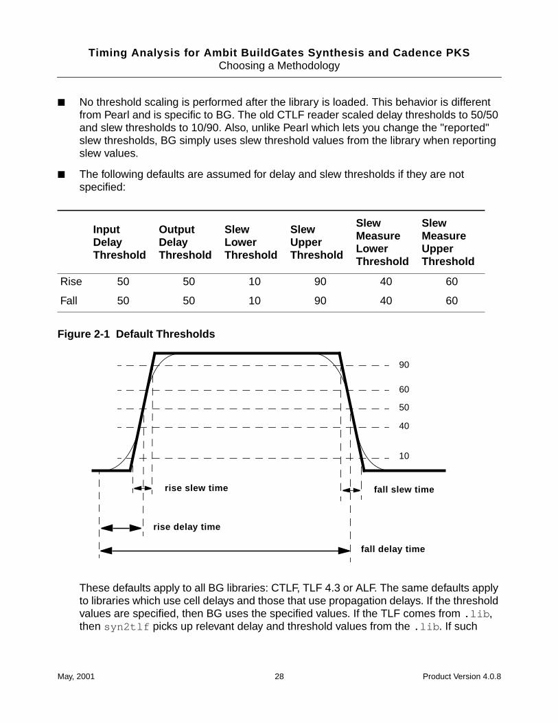
■ The following defaults are assumed for delay and slew thresholds if they are notspecified:
Figure 2-1 Default Thresholds
These defaults apply to all BG libraries: CTLF, TLF 4.3 or ALF. The same defaults applyto libraries which use cell delays and those that use propagation delays. If the thresholdvalues are specified, then BG uses the specified values. If the TLF comes from .lib ,then syn2tlf picks up relevant delay and threshold values from the .lib . If such
InputDelayThreshold
OutputDelayThreshold
SlewLowerThreshold
SlewUpperThreshold
SlewMeasureLowerThreshold
SlewMeasureUpperThreshold
Rise 50 50 10 90 40 60
Fall 50 50 10 90 40 60
90
60
50
40
10
fall slew time
fall delay time
rise slew time
rise delay time
May, 2001 28 Product Version 4.0.8
Timing Analysis for Ambit BuildGates Synthesis and Cadence PKSChoosing a Methodology
values are not present, syn2tlf forces you to specify them. No defaults are assumedin syn2tlf .
Tip
It is not advisable to mix TLF 4.3, 4.1 and CTLF libraries.
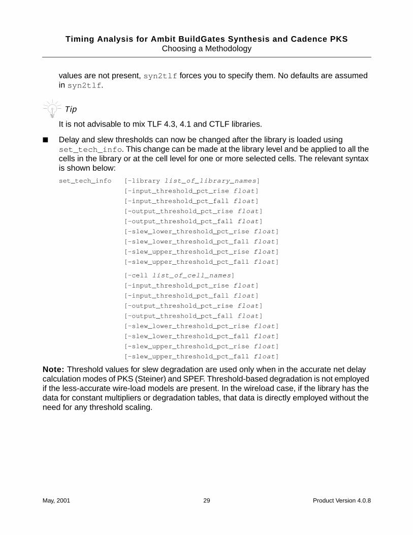
■ Delay and slew thresholds can now be changed after the library is loaded usingset_tech_info . This change can be made at the library level and be applied to all thecells in the library or at the cell level for one or more selected cells. The relevant syntaxis shown below:
set_tech_info [-library list_of_library_names ]
[-input_threshold_pct_rise float ]
[-input_threshold_pct_fall float ]
[-output_threshold_pct_rise float ]
[-output_threshold_pct_fall float ]
[-slew_lower_threshold_pct_rise float ]
[-slew_lower_threshold_pct_fall float ]
[-slew_upper_threshold_pct_rise float ]
[-slew_upper_threshold_pct_fall float ]
[-cell list_of_cell_names ]
[-input_threshold_pct_rise float ]
[-input_threshold_pct_fall float ]
[-output_threshold_pct_rise float ]
[-output_threshold_pct_fall float ]
[-slew_lower_threshold_pct_rise float ]
[-slew_lower_threshold_pct_fall float ]
[-slew_upper_threshold_pct_rise float ]
[-slew_upper_threshold_pct_fall float ]
Note: Threshold values for slew degradation are used only when in the accurate net delaycalculation modes of PKS (Steiner) and SPEF. Threshold-based degradation is not employedif the less-accurate wire-load models are present. In the wireload case, if the library has thedata for constant multipliers or degradation tables, that data is directly employed without theneed for any threshold scaling.
May, 2001 29 Product Version 4.0.8
Timing Analysis for Ambit BuildGates Synthesis and Cadence PKSChoosing a Methodology
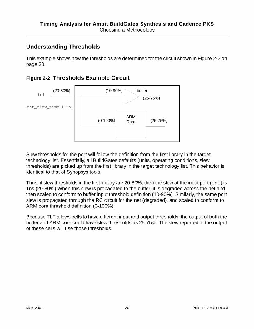
Understanding Thresholds
This example shows how the thresholds are determined for the circuit shown in Figure 2-2 onpage 30.
Figure 2-2 Thresholds Example Circuit
Slew thresholds for the port will follow the definition from the first library in the targettechnology list. Essentially, all BuildGates defaults (units, operating conditions, slewthresholds) are picked up from the first library in the target technology list. This behavior isidentical to that of Synopsys tools.
Thus, if slew thresholds in the first library are 20-80%, then the slew at the input port (in1 ) is1ns (20-80%).When this slew is propagated to the buffer, it is degraded across the net andthen scaled to conform to buffer input threshold definition (10-90%). Similarly, the same portslew is propagated through the RC circuit for the net (degraded), and scaled to conform toARM core threshold definition (0-100%)
Because TLF allows cells to have different input and output thresholds, the output of both thebuffer and ARM core could have slew thresholds as 25-75%. The slew reported at the outputof these cells will use those thresholds.
ARMCore
(10-90%)
(0-100%)
(20-80%) bufferin1
(25-75%)
(25-75%)
set_slew_time 1 in1
May, 2001 30 Product Version 4.0.8

Timing Analysis for Ambit BuildGates Synthesis and Cadence PKSChoosing a Methodology
May, 2001 31 Product Version 4.0.8

Timing Analysis for Ambit BuildGates Synthesis and Cadence PKSChoosing a Methodology
May, 2001 32 Product Version 4.0.8
Timing Analysis for Ambit BuildGates Synthesis and Cadence PKS
3Using Timing Libraries
This chapter describes how to use various library formats for static timing analysis in Ambit®
BuildGates® synthesis and Cadence® physically knowledgeable synthesis (PKS)environments. This chapter contains the following information:
■ Reading Timing Libraries on page 34
❑ Using Cadence TLF Libraries on page 36
❑ Using Synopsys .lib Libraries on page 43
❑ Using Synopsys Stamp Models on page 51
❑ Using IEEE 1481 Delay and Power Calculation System (DCL) Libraries on page 54
❑ Using OLA v1.0.2 Libraries on page 60
■ Specifying Target Technology Libraries on page 62
■ Linking Cells to a Target Technology Library on page 63
■ Getting Library Information on page 64
May, 2001 33 Product Version 4.0.8
Timing Analysis for Ambit BuildGates Synthesis and Cadence PKSUsing Timing Libraries
Reading Timing Libraries
Before performing any timing analysis you must read in the timing information for your design.Timing models are contained in the library provided by the ASIC or intellectual property (IP)vendor.
Cadence® timing analysis currently supports the following library formats:
■ Cadence® TLF v4.3
■ Synopsys .lib
■ Synopsys Stamp Models
■ IEEE 1481 DCL
■ OLA v1.0.2
The libraries are summarized in Table 3-1 on page 34 and discussed in the sections thatfollow. Each library description contains four sections:
■ Source Format
Discusses the source format. Some libraries require conversion before being read. Thissection also lists unsupported features (if any).
■ Loading the Library
Describes how to load the library into the database. This section also tells whether or notthe timing library contains synthesis and power information.
■ Wire-load Models
Describes how Cadence timing analysis uses the wire-load models from the library.
■ Operating Conditions
Describes how Cadence timing analysis uses the operating conditions defined in thelibrary.
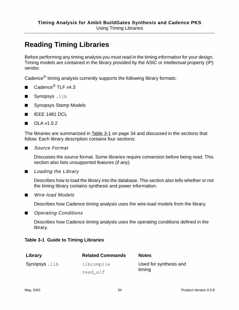
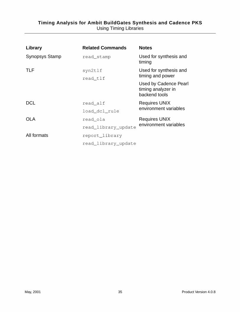
Table 3-1 Guide to Timing Libraries
Library Related Commands Notes
Synopsys .lib libcompile
read_alf
Used for synthesis andtiming
May, 2001 34 Product Version 4.0.8
Timing Analysis for Ambit BuildGates Synthesis and Cadence PKSUsing Timing Libraries
Synopsys Stamp read_stamp Used for synthesis andtiming
TLF syn2tlf
read_tlf
Used for synthesis andtiming and power
Used by Cadence Pearltiming analyzer inbackend tools
DCL read_alf
load_dcl_rule
Requires UNIXenvironment variables
OLA read_ola
read_library_update
Requires UNIXenvironment variables
All formats report_library
read_library_update
Library Related Commands Notes
May, 2001 35 Product Version 4.0.8
Timing Analysis for Ambit BuildGates Synthesis and Cadence PKSUsing Timing Libraries
Using Cadence TLF Libraries
This section describes how to use Cadence Timing Library Format (TLF) libraries with AmbitBuildGates synthesis. All references to TLF in this section refer to TLF v4.3.
TLF Source Format
TLF is the common repository of timing model information in the Cadence backend timingflow and is the primary timing model format for Pearl. The primary advantage of using thesame TLF library for both Ambit BuildGates (synthesis and timing) and Pearl (the timingengine for Silicon Ensemble) is that one library can be used for the entire synthesis place androute flow.
For more information on the TLF, see the Timing Library Format Reference Manual in thePearl documentation set. Your local Cadence field office can also assist in converting existinglibraries to TLF 4.3.
The terms TLF and .tlf are used interchangeably throughout this section. When using TLFor .tlf , the text typically refers to the constructs in the TLF standard or to the actual librarysource. When using .ctlf , the text refers to a TLF library compiled by the obsolete utilitytlfc . Compiled files are no longer supported. Vendors usually provide encrypted TLF.
Loading .tlf Libraries
Libraries in the .tlf format can be used for synthesis, timing, and power analysis. A .tlflibrary file (either encrypted or unencrypted) is loaded into Cadence timing analysis using theread_tlf command.
To support existing design databases, read_tlf also loads .ctlf files. However, supportfor CTLF is being phased out. It is recommended that you obtain a TLF source file version 4.3or higher. If the TLF (or CTLF) was generated from .lib , you can use the latest version ofsyn2tlf to generate a v4.3 (or higher) TLF file.
➤ To read a .tlf use the read_tlf command as shown in the following examples:
read_tlf my.tlf
read_tlf myold.ctlf
For command options, see read_tlf in the Command Reference for Ambit BuildGatesSynthesis and Cadence PKS.
May, 2001 36 Product Version 4.0.8
Timing Analysis for Ambit BuildGates Synthesis and Cadence PKSUsing Timing Libraries
Merging TLF Libraries
The read_library_update command supports a merge from a second .tlf library intoan existing .tlf library in memory. The following example appends cells from thesecond.tlf library to the first.tlf library:
read_tlf first.tlf
read_library_update second.tlf
The read_library_update command can also be used to merge wire-loads, RAMs,custom timing models, or additional standard cells from a .lib or .alf library into a .tlflibrary in memory. For more information, see read_library_update in the CommandReference for Ambit BuildGates Synthesis and Cadence PKS.
Reading Multiple TLF Libraries
➤ To analyze an existing netlist containing cells from multiple TLF libraries, load each TLFlibrary with a separate read_tlf command. For example:
read_tlf ram.tlf
read_tlf cpu.tlf
Note: The individual libraries must be loaded before executing the do_build_genericcommand, which links the technology cells to the instances in the netlist.
Wire-load Models in .tlf
TLF libraries and .lib libraries have a similar representation for wire-load models. For thisreason, using TLF libraries for wire-load support in Cadence timing analysis is very similar tothe wire-load support described in “Wire-load Models in .lib Libraries” on page 47.
Operating Conditions
TLF supports named operating conditions like those available in the .lib standard. Theset_operating_condition , set_operating_parameter andget_operating_parameter commands can be used with .tlf libraries.
Unlike a .lib library, a .tlf library can define a set of lookup tables (in addition to linearmodels) to specify delay and slew variations with respect to process, temperature andvoltage. These variations are modeled by process, voltage, and temperature (PVT)multipliers. However, read_tlf in Cadence timing analysis supports only linear models forPVT multipliers.
May, 2001 37 Product Version 4.0.8
Timing Analysis for Ambit BuildGates Synthesis and Cadence PKSUsing Timing Libraries
Statetables in TLF Libraries
Statetables model the behavior of sequential logic. You can use statetables to model
■ Generic sequential functionality in an easy to understand format
■ Complex sequential cells
While simplistic flip-flop or latch descriptions have limitations in supporting complexsequential cells, statetables can be used in complex macro-cells such as shift-registersand counters.
■ Truthtables from vendor databooks
Another common application arises from the presence of truthtables in ASIC vendordatabooks. The library developer can easily translate databook truthtables intostatetables. Because these representations are also useful for Verilog or VHDLsimulations, many libraries end up having statetables. Synthesis tools need to be able tounderstand and map to those cells with statetables.
Important
In releases before 4.0.8, statetables were not supported. A ff{} or latch{}primitive existing in the same cell definition as state_table{} was used instead,if it was defined.
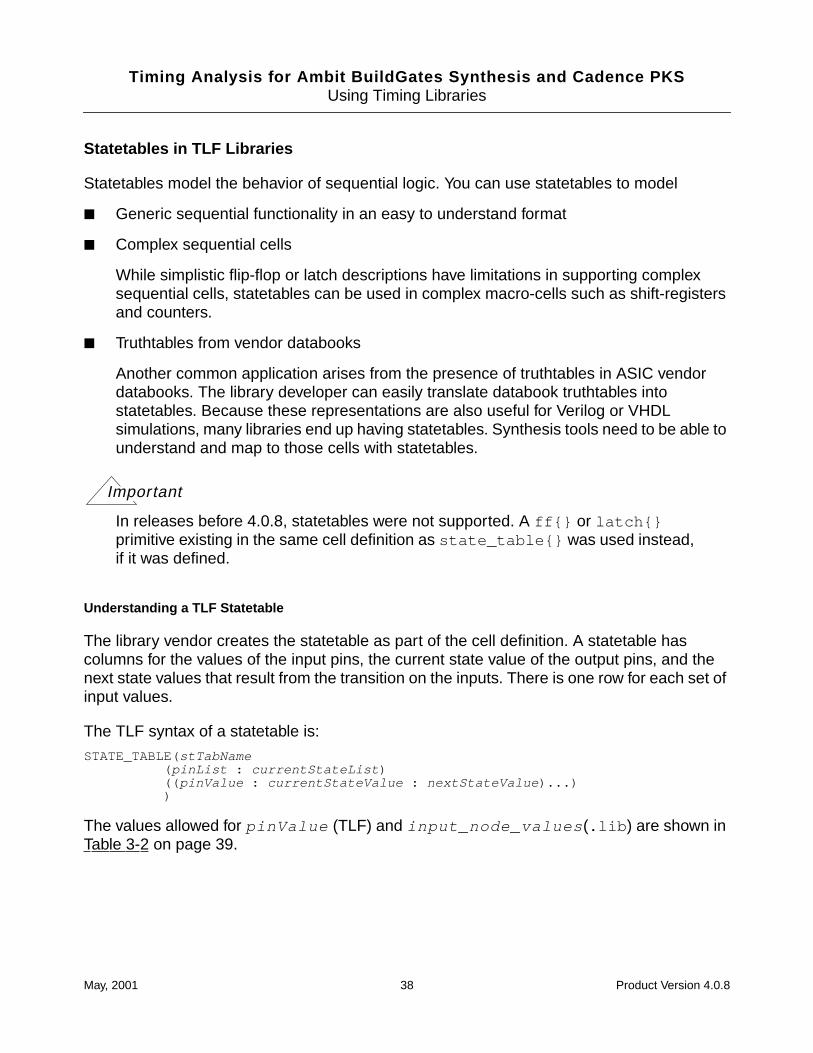
Understanding a TLF Statetable
The library vendor creates the statetable as part of the cell definition. A statetable hascolumns for the values of the input pins, the current state value of the output pins, and thenext state values that result from the transition on the inputs. There is one row for each set ofinput values.
The TLF syntax of a statetable is:
STATE_TABLE(stTabName( pinList : currentStateList )(( pinValue : currentStateValue : nextStateValue )...))
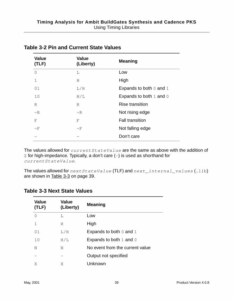
The values allowed for pinValue (TLF) and input_node_values (.lib ) are shown inTable 3-2 on page 39.
May, 2001 38 Product Version 4.0.8
Timing Analysis for Ambit BuildGates Synthesis and Cadence PKSUsing Timing Libraries
The values allowed for currentStateValue are the same as above with the addition ofZ for high-impedance. Typically, a don’t care (- ) is used as shorthand forcurrentStateValue .
The values allowed for nextStateValue (TLF) and next_internal_values (.lib )are shown in Table 3-3 on page 39.
Table 3-2 Pin and Current State Values
Value(TLF)
Value(Liberty) Meaning
0 L Low
1 H High
01 L/H Expands to both 0 and 1
10 H/L Expands to both 1 and 0
R R Rise transition
~R ~R Not rising edge
F F Fall transition
~F ~F Not falling edge
- - Don’t care
Table 3-3 Next State Values
Value(TLF)
Value(Liberty) Meaning
0 L Low
1 H High
01 L/H Expands to both 0 and 1
10 H/L Expands to both 1 and 0
N N No event from the current value
- - Output not specified
X X Unknown
May, 2001 39 Product Version 4.0.8
Timing Analysis for Ambit BuildGates Synthesis and Cadence PKSUsing Timing Libraries
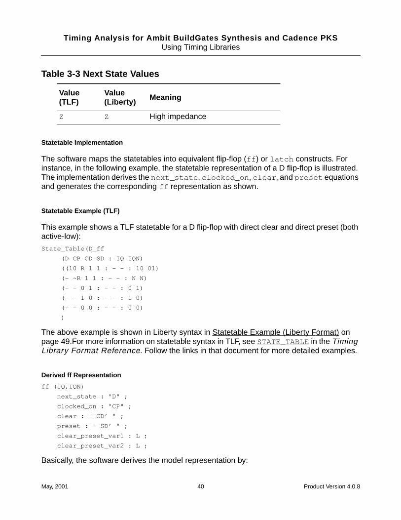
Statetable Implementation
The software maps the statetables into equivalent flip-flop (ff ) or latch constructs. Forinstance, in the following example, the statetable representation of a D flip-flop is illustrated.The implementation derives the next_state , clocked_on , clear , and preset equationsand generates the corresponding ff representation as shown.
Statetable Example (TLF)
This example shows a TLF statetable for a D flip-flop with direct clear and direct preset (bothactive-low):
State_Table(D_ff
(D CP CD SD : IQ IQN)
((10 R 1 1 : - - : 10 01)
(- ~R 1 1 : - - : N N)
(- - 0 1 : - - : 0 1)
(- - 1 0 : - - : 1 0)
(- - 0 0 : - - : 0 0)
)
The above example is shown in Liberty syntax in Statetable Example (Liberty Format) onpage 49.For more information on statetable syntax in TLF, see STATE_TABLEin the TimingLibrary Format Reference. Follow the links in that document for more detailed examples.
Derived ff Representation
ff (IQ,IQN)
next_state : "D" ;
clocked_on : "CP" ;
clear : " CD’ " ;
preset : " SD’ " ;
clear_preset_var1 : L ;
clear_preset_var2 : L ;
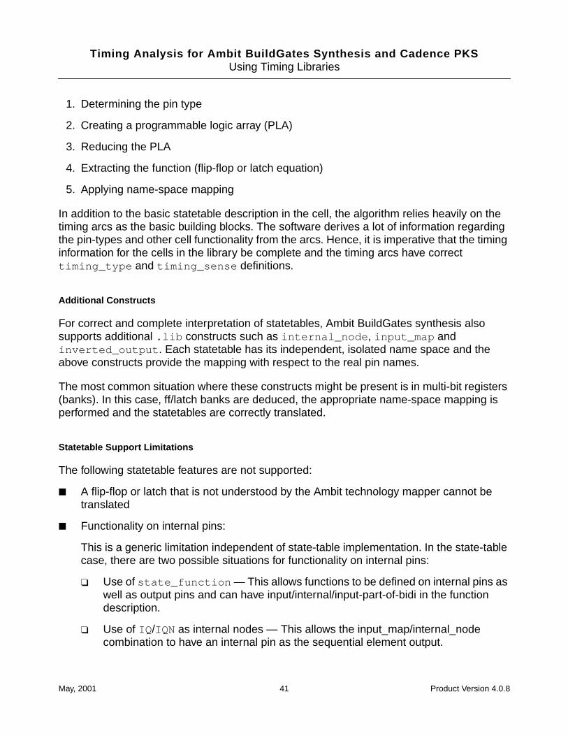
Basically, the software derives the model representation by:
Z Z High impedance
Table 3-3 Next State Values
Value(TLF)
Value(Liberty) Meaning
May, 2001 40 Product Version 4.0.8
Timing Analysis for Ambit BuildGates Synthesis and Cadence PKSUsing Timing Libraries
1. Determining the pin type
2. Creating a programmable logic array (PLA)
3. Reducing the PLA
4. Extracting the function (flip-flop or latch equation)
5. Applying name-space mapping
In addition to the basic statetable description in the cell, the algorithm relies heavily on thetiming arcs as the basic building blocks. The software derives a lot of information regardingthe pin-types and other cell functionality from the arcs. Hence, it is imperative that the timinginformation for the cells in the library be complete and the timing arcs have correcttiming_type and timing_sense definitions.
Additional Constructs
For correct and complete interpretation of statetables, Ambit BuildGates synthesis alsosupports additional .lib constructs such as internal_node , input_map andinverted_output . Each statetable has its independent, isolated name space and theabove constructs provide the mapping with respect to the real pin names.
The most common situation where these constructs might be present is in multi-bit registers(banks). In this case, ff/latch banks are deduced, the appropriate name-space mapping isperformed and the statetables are correctly translated.
Statetable Support Limitations
The following statetable features are not supported:
■ A flip-flop or latch that is not understood by the Ambit technology mapper cannot betranslated
■ Functionality on internal pins:
This is a generic limitation independent of state-table implementation. In the state-tablecase, there are two possible situations for functionality on internal pins:
❑ Use of state_function — This allows functions to be defined on internal pins aswell as output pins and can have input/internal/input-part-of-bidi in the functiondescription.
❑ Use of IQ /IQN as internal nodes — This allows the input_map/internal_nodecombination to have an internal pin as the sequential element output.
May, 2001 41 Product Version 4.0.8

Timing Analysis for Ambit BuildGates Synthesis and Cadence PKSUsing Timing Libraries
■ Multiple sequential cells such as master-slave pairs, shift registers, and counters
■ A single cell with two latches that have different timing information. For example, onelatch with regular output and the other with tri-state output.
■ dcm_timing true — No ff/latch functionality derivation from statetables for DCL/OLA.
May, 2001 42 Product Version 4.0.8
Timing Analysis for Ambit BuildGates Synthesis and Cadence PKSUsing Timing Libraries
Using Synopsys .lib Libraries
This section describes how to use Synopsys Liberty (.lib) libraries with Ambit BuildGates.
.lib and .alf Source Format
The .lib format is the ASCII synthesis, timing, and power library format originally defined bySynopsys and now licensed by Synopsys through the TAP-in program. Cadence is a TAP-inlicensee.
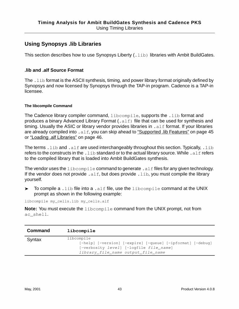
The libcompile Command
The Cadence library compiler command, libcompile , supports the .lib format andproduces a binary Advanced Library Format (.alf) file that can be used for synthesis andtiming. Usually the ASIC or library vendor provides libraries in .alf format. If your librariesare already compiled into .alf , you can skip ahead to “Supported .lib Features” on page 45or “Loading .alf Libraries” on page 46.
The terms .lib and .alf are used interchangeably throughout this section. Typically, .librefers to the constructs in the .lib standard or to the actual library source. While .alf refersto the compiled library that is loaded into Ambit BuildGates synthesis.
The vendor uses the libcompile command to generate .alf files for any given technology.If the vendor does not provide .alf , but does provide .lib , you must compile the libraryyourself.
➤ To compile a .lib file into a .alf file, use the libcompile command at the UNIXprompt as shown in the following example:
libcompile my_cells.lib my_cells.alf
Note: You must execute the libcompile command from the UNIX prompt, not fromac_shell .
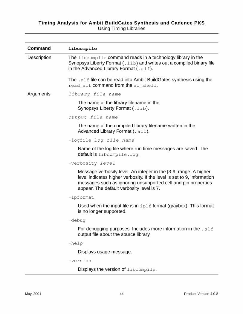
Command libcompile
Syntax libcompile[-help] [-version] [-expire] [-queue] [-ipformat] [-debug][-verbosity level ] [-logfile file_name ]library_file_name output_file_name
May, 2001 43 Product Version 4.0.8
Timing Analysis for Ambit BuildGates Synthesis and Cadence PKSUsing Timing Libraries
Description The libcompile command reads in a technology library in theSynopsys Liberty Format (.lib ) and writes out a compiled binary filein the Advanced Library Format (.alf ).
The .alf file can be read into Ambit BuildGates synthesis using theread_alf command from the ac_shell .
Arguments library_file_name
The name of the library filename in theSynopsys Liberty Format (.lib ).
output_file_name
The name of the compiled library filename written in theAdvanced Library Format (.alf ).
-logfile log_file_name
Name of the log file where run time messages are saved. Thedefault is libcompile.log .
-verbosity level
Message verbosity level. An integer in the [3-9] range. A higherlevel indicates higher verbosity. If the level is set to 9, informationmessages such as ignoring unsupported cell and pin propertiesappear. The default verbosity level is 7.
-ipformat
Used when the input file is in iplf format (graybox). This formatis no longer supported.
-debug
For debugging purposes. Includes more information in the .alfoutput file about the source library.
-help
Displays usage message.
-version
Displays the version of libcompile .
Command libcompile
May, 2001 44 Product Version 4.0.8
Timing Analysis for Ambit BuildGates Synthesis and Cadence PKSUsing Timing Libraries
Supported .lib Features
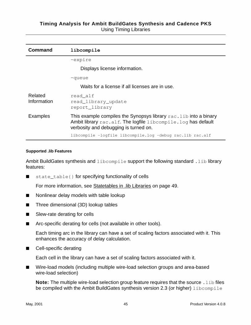
Ambit BuildGates synthesis and libcompile support the following standard .lib libraryfeatures:
■ state_table{} for specifying functionality of cells
For more information, see Statetables in .lib Libraries on page 49.
■ Nonlinear delay models with table lookup
■ Three dimensional (3D) lookup tables
■ Slew-rate derating for cells
■ Arc-specific derating for cells (not available in other tools).
Each timing arc in the library can have a set of scaling factors associated with it. Thisenhances the accuracy of delay calculation.
■ Cell-specific derating
Each cell in the library can have a set of scaling factors associated with it.
■ Wire-load models (including multiple wire-load selection groups and area-basedwire-load selection)
Note: The multiple wire-load selection group feature requires that the source .lib filesbe compiled with the Ambit BuildGates synthesis version 2.3 (or higher) libcompile
-expire
Displays license information.
-queue
Waits for a license if all licenses are in use.
RelatedInformation
read_alfread_library_updatereport_library
Examples This example compiles the Synopsys library rac.lib into a binaryAmbit library rac.alf . The logfile libcompile.log has defaultverbosity and debugging is turned on.
libcompile -logfile libcompile.log -debug rac.lib rac.alf
Command libcompile
May, 2001 45 Product Version 4.0.8
Timing Analysis for Ambit BuildGates Synthesis and Cadence PKSUsing Timing Libraries
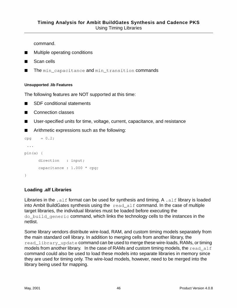
command.
■ Multiple operating conditions
■ Scan cells
■ The min_capacitance and min_transition commands
Unsupported .lib Features
The following features are NOT supported at this time:
■ SDF conditional statements
■ Connection classes
■ User-specified units for time, voltage, current, capacitance, and resistance
■ Arithmetic expressions such as the following:
cpg = 0.2;
...
pin(a) {
direction : input;
capacitance : 1.000 * cpg;
}
Loading .alf Libraries
Libraries in the .alf format can be used for synthesis and timing. A .alf library is loadedinto Ambit BuildGates synthesis using the read_alf command. In the case of multipletarget libraries, the individual libraries must be loaded before executing thedo_build_generic command, which links the technology cells to the instances in thenetlist.
Some library vendors distribute wire-load, RAM, and custom timing models separately fromthe main standard cell library. In addition to merging cells from another library, theread_library_update command can be used to merge these wire-loads, RAMs, or timingmodels from another library. In the case of RAMs and custom timing models, the read_alfcommand could also be used to load these models into separate libraries in memory sincethey are used for timing only. The wire-load models, however, need to be merged into thelibrary being used for mapping.
May, 2001 46 Product Version 4.0.8
Timing Analysis for Ambit BuildGates Synthesis and Cadence PKSUsing Timing Libraries
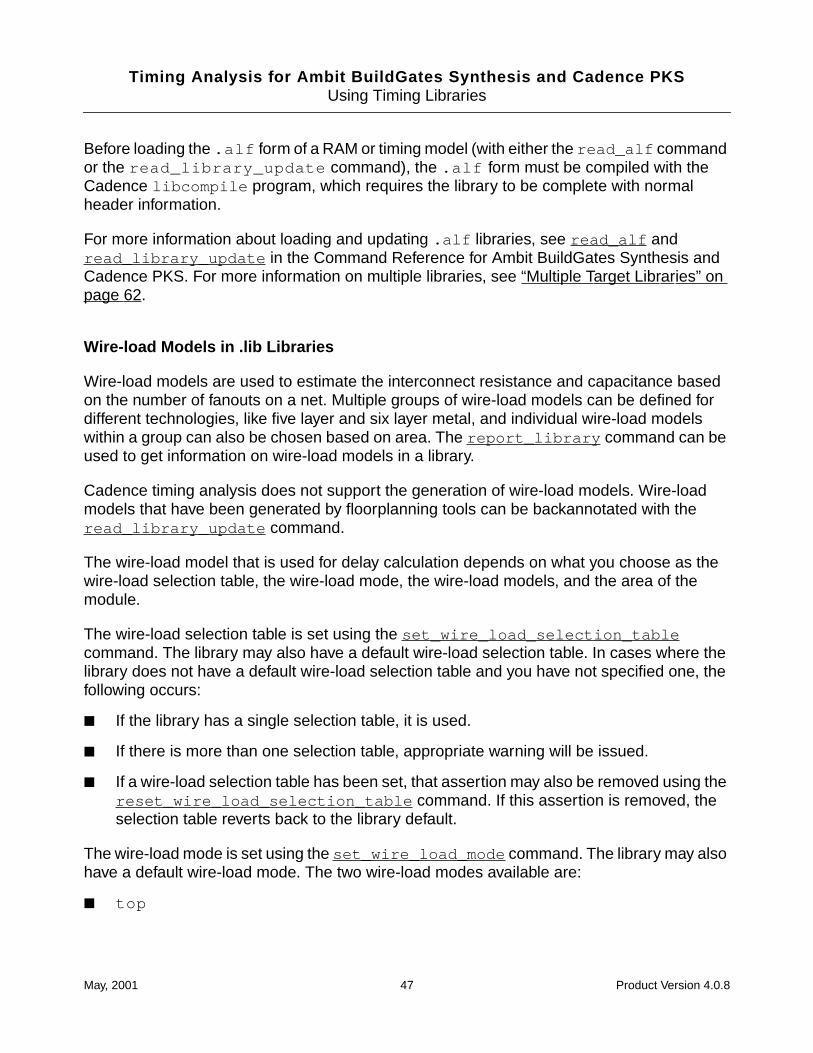
Before loading the .alf form of a RAM or timing model (with either the read_alf commandor the read_library_update command), the .alf form must be compiled with theCadence libcompile program, which requires the library to be complete with normalheader information.
For more information about loading and updating .alf libraries, see read_alf andread_library_update in the Command Reference for Ambit BuildGates Synthesis andCadence PKS. For more information on multiple libraries, see “Multiple Target Libraries” onpage 62.
Wire-load Models in .lib Libraries
Wire-load models are used to estimate the interconnect resistance and capacitance basedon the number of fanouts on a net. Multiple groups of wire-load models can be defined fordifferent technologies, like five layer and six layer metal, and individual wire-load modelswithin a group can also be chosen based on area. The report_library command can beused to get information on wire-load models in a library.
Cadence timing analysis does not support the generation of wire-load models. Wire-loadmodels that have been generated by floorplanning tools can be backannotated with theread_library_update command.
The wire-load model that is used for delay calculation depends on what you choose as thewire-load selection table, the wire-load mode, the wire-load models, and the area of themodule.
The wire-load selection table is set using the set_wire_load_selection_tablecommand. The library may also have a default wire-load selection table. In cases where thelibrary does not have a default wire-load selection table and you have not specified one, thefollowing occurs:
■ If the library has a single selection table, it is used.
■ If there is more than one selection table, appropriate warning will be issued.
■ If a wire-load selection table has been set, that assertion may also be removed using thereset_wire_load_selection_table command. If this assertion is removed, theselection table reverts back to the library default.
The wire-load mode is set using the set_wire_load_mode command. The library may alsohave a default wire-load mode. The two wire-load modes available are:
■ top
May, 2001 47 Product Version 4.0.8
Timing Analysis for Ambit BuildGates Synthesis and Cadence PKSUsing Timing Libraries
Setting the mode to top uses the area of the largest block enclosing the net to select thewire-load model from the wire-load selection table. The default wire-load mode is top ifnot defaulted in the library.
■ enclosed
Setting the mode to enclosed uses the area of the smallest block enclosing a net toselect the wire-load model.
The wire-load model for a particular module can be manually set by using theset_wire_load command. If the set_wire_load command is used, it can be removedusing the reset_wire_load command. Upon removing this assertion, the wire-load modelis then automatically selected depending on the wire-load mode and the wire-load selectiontable specified.
Without manual override, Cadence timing analysis selects the appropriate wire-load modelfrom the library (during synthesis) using an area based wire-load selection table. Wire-loadmodel selection is based on module area, which is the sum of the area of all the cells in themodule and its submodules.
Operating Conditions in .lib Libraries
Operating conditions are used to define the process, voltage, temperature (PVT), and theinterconnect tree type (balanced, star, best, or worst topology) with which timing calculationswill be performed. Operating conditions are defined in the library and allow you to select adefault operating condition. In Cadence timing analysis, you can select a predefinedoperating condition and also individually change the PVT parameters. Additionally, you maychoose to use one operating condition or manually specified PVT for late mode paths andanother operating condition or manually specified PVT for early mode paths. This featureallows for simultaneous analysis and optimization of worst and best case operating conditionson early and late paths.
Predefined operating conditions from the library may be selected using theset_operating_condition command. The library may also contain a default operatingcondition which is used if you do not manually select an operating condition. Process, voltage,or temperature can be individually changed from the current value set by the default operatingcondition by using the set_operating_parameter command. For both commands, the-pvt option can be used to take advantage of the simultaneous analysis capabilities. Formore information about simultaneous analysis, refer to “Analyzing Simultaneous Best Caseand Worst Case Off-Chip Variation” on page 214.These parameters can be retrieved usingthe get_operating_parameter command.
Note: In a .lib library, only one set of lookup tables is defined, which returns the delay andslew of a specific process, temperature, and voltage. Whenever the process, temperature, orvoltage is varied, linear derating factors multiplied by results from the lookup table are usedto calculate delays and slews.
May, 2001 48 Product Version 4.0.8
Timing Analysis for Ambit BuildGates Synthesis and Cadence PKSUsing Timing Libraries
Statetables in .lib Libraries
General information about statetables is provided in Statetables in TLF Libraries on page 38.After statetables in Liberty (.lib ) format are read in by read_alf they are implemented inthe same manner as statetables in TLF libraries. The same limitations described in StatetableSupport Limitations on page 41 also apply to statetables in Liberty format.
Important
In releases before 4.0.8, statetables were not supported. A ff{} or latch{}primitive existing in the same cell definition as state_table{} was used instead,if it was defined. If you want to take advantage of the new statetable support, youmust recompile with the latest libcompile and read in the resulting ALF withread_alf in order to get the statetables into the database.
Understanding a Liberty Statetable
The library vendor creates the statetable as part of the cell definition. In Liberty, a sequentialcell can have only one statetable in the cell definition. The Liberty syntax of a statetable is
statetable(“ input_node_names ” , “ internal_node_names ”)
{table : “ input_node_values : current_internal_values : next_internal_values ,
input_node_values : current_internal_values : next_internal_values ”;
}
The values for input_node_values are shown in Table 3-2 on page 39 The valuesallowed for current_internal_values are the same with the addition of Z forhigh-impedance. Typically, a don’t care (- ) is used as shorthand forcurrent_internal_values .
The values allowed for next_internal_values are shown in Table 3-3 on page 39.
Statetable Example (Liberty Format)
This example statetable models the same D flip-flop as discussed in Statetable Example(TLF) on page 40.
statetable("D CP CD SD","IQ IQN") {
table : "H/L R H H : - - : H/L L/H,\
- ~R H H : - - : N N,\
- - L H : - - : L H,\
- - H L : - - : H L,\
- - L L : - - : L L";
}
May, 2001 49 Product Version 4.0.8
Timing Analysis for Ambit BuildGates Synthesis and Cadence PKSUsing Timing Libraries
For more information about statetables in .lib format, see the Synopsys Libertydocumentation.
May, 2001 50 Product Version 4.0.8
Timing Analysis for Ambit BuildGates Synthesis and Cadence PKSUsing Timing Libraries
Using Synopsys Stamp Models
This section describes how to use Synopsys models in Stamp format with Cadence timinganalysis. The Stamp model can be extracted from Synopsys PrimeTime timing analysis tool.See the Synopsys documentation for more information about creating Stamp models.
Stamp Model Source Format
The Stamp modeling language is a Synopsys proprietary language developed specifically todescribe the timing models of large custom blocks, such as RAMs and microprocessor coresthat have not been synthesized into gate-level netlists.
The Stamp model describes the interface timing of the block and consists of two parts:
■ Model file (technology-independent information)
Describes the ports, timing modes, and interface timing arcs. The filename has a .modsuffix. For example, DMA.mod.
■ Model data file (technology-dependent information)
Contains actual delay values and constraints for arcs in the model file. The filename hasa .data suffix. For example, DMA.data .
Unsupported Stamp Features
All Stamp features are supported except for the following:
■ Timing arc labels and comments
In Stamp, timing arcs have a label and optional comments. Cadence timing analysisignores labels and comments.
■ Shorted ports
In a Stamp model a set of pins can be declared to be shorted (electrically connected)pins. Shorted pins are used to model feedthrough pins (an input port going directly to anoutput port). Shorts also model multiple output ports that are internally connected to thesame gate output. Currently, Ambit synthesis and timing analysis ignores SHORTstatements, all connectivity information comes from the netlist.
■ Generated clocks
Stamp allows the creation of new clocks that have been derived from the master clock.Currently neither Synopsys Design Compiler or Ambit synthesis tools support generatedclocks. You must create the derived clocks manually.
May, 2001 51 Product Version 4.0.8
Timing Analysis for Ambit BuildGates Synthesis and Cadence PKSUsing Timing Libraries
■ MINCAP and MINTRANS
Only MAXCAP and MAXTRANS are supported at the present time.
■ Drive arc
This pin property is an extra delay associated with an output. You can model this featureby using an internal pin. All delay arcs which drive the pin with this property also drivethe internal pin. The drive arc data is used to create an arc from the internal pin to theactual pin.
■ EQUIVALENT pins
The Stamp EQUIVALENT pin property is not supported. You can add dummy internalpins to get the same effect. For example, if two inputs A and B are equivalent, add a newinternal pin Nsuch that there is a zero delay arc from A to Nand from B to Nand Ndrivesall pins driven by A and B.
Loading Stamp Models
A Stamp model is used for synthesis and timing. You should verify the Stamp model usingPrimeTime before using the model in Cadence timing analysis.
The Stamp model is loaded using the read_stamp command. The command requires twoarguments, one for the model file and one for the model data file. The -mod argumentspecifies the name of the Stamp model. The model data file is specified by the -min , -typor -max argument. The -min argument specifies the best case operating condition, -typindicates typical case operating condition and -max the worst case operating condition. If the-min , -typ or -max argument is omitted, the default is -typ . For example, the followingloads the ram.data into the typical operating condition field of the library:
read_stamp -model ram.mod ram.data
You can load multiple operating conditions simultaneously by combining -min , -typ, or-max arguments. For example, the following loads ram_min.data into the best caseoperating condition field and ram_max.data into the worst case operating field of the library:
read_stamp -model ram.mod -min ram_min.data -max ram_max.data
For more information about the command, see read_stamp in the Command Reference forAmbit BuildGates Synthesis and Cadence PKS.
May, 2001 52 Product Version 4.0.8
Timing Analysis for Ambit BuildGates Synthesis and Cadence PKSUsing Timing Libraries
Wire-load Models in Stamp Models
Wire-load models are part of the Stamp model if they were present when the model wasextracted. See the Synopsys PrimeTime documentation for more information about preparinga design for extraction with wire-load models or backannotated parasitics and delays.
Operating Conditions in Stamp Models
Operating conditions are optionally specified in the Stamp model. They are the operatingconditions under which the model was extracted. Prime Time adds an_opcondname .data suffix to the model data file when the -operating_conditionsoption is used to generate the model. More than one operating condition can be specified atthe time of model generation. This results in two data files for the model. For example,PrimeTime extracts values for a DSP core under best-case commercial conditions (BCCOM)then worst-case (WCCOM) and creates a STAMPmodel file named dsp.mod and two STAMPdata files named dsp_BCCOM.data and dsp_WCCOM.data. Both data files can be read insimultaneously by the following command:
read_stamp -model dsp.mod -min dsp_BCCOM.data -max dsp_WCCOM.data
May, 2001 53 Product Version 4.0.8
Timing Analysis for Ambit BuildGates Synthesis and Cadence PKSUsing Timing Libraries
Using IEEE 1481 Delay and Power Calculation System (DCL) Libraries
This section describes how to use IEEE 1481 Delay and Power Calculation System (DPCS)libraries with Cadence timing analysis.
Source Format
The Delay Calculation Language (DCL) is a language standardized by IEEE for representingtiming and power in DPCS. All references to DCL in this section refer to standard IEEE 1481DPCS v1.0.
Since DCL is an actual language as opposed to a library format containing lookup tables, thelibrary developer creating libraries with DCL has greater flexibility. The library developer canmodel cell and interconnect delays and slews in ways which suit the application using thelibrary, or in ways which better model the process technology. For applications like synthesis,which require high performance, the library developer may choose to model delays and slewswith lookup tables. For applications that require high accuracy, like static timing signoff, thelibrary developer may choose to model delays and slews with high-order equations or calls toexternal delay calculators written in C or Spice applications.
Note: One DCL library can contain both styles of modeling such that the same DCL librarycan be used in the design flow from initial synthesis, through physical design, and to finalstatic timing signoff.
The DCL compiler, ndcl , compiles DCL into a binary Delay and Power Calculation Module(DPCM). The DPCM is an executable shared library that is linked to an application (like AmbitBuildGates synthesis) at runtime. The DCL compiler is available through Cadence for librarydevelopment purposes. For library distribution rights, the DCL compiler must be purchasedfrom Si2 which is a not-for-profit organization of industry-leading silicon systems and toolcompanies focused on improving productivity and reducing cost in creating and producingintegrated silicon systems. To contact Si2, refer to the following URL:
http://www.si2.org
To obtain more information about DCL, refer to the following URLs:
http://www.si2.org/dcl
http://www.eda.org/vi/dpc
Si2 also provides DCL templates for converting existing libraries to DCL.
May, 2001 54 Product Version 4.0.8

Timing Analysis for Ambit BuildGates Synthesis and Cadence PKSUsing Timing Libraries
Loading DCL Libraries with a DPCM
Libraries written in DCL can be used for synthesis, timing, and power. However, DPCSlibraries do not contain cell function or properties like dont_utilize or dont_modify thatare used in synthesis.
Loading DCL libraries is a multi-step process. First you must set some environment variables.Then you load a .alf library using the read_alf command, then a DCL library (or moreaccurately a DPCM) is loaded on top of the .alf using the load_dcl_rule command.When the DPCM library is loaded over a .alf , all timing information is derived from theDPCM, while cell function is derived from the .alf . If the DPCM contains cell properties (likearea) and pin properties (like capacitance and wire load), the DPCM takes precedence overthe .alf and overrides any similar information provided by the .alf . If the DPCM does notcontain this information, the cell and pin properties and wire-load models from the .alf areused.
To map to multiple libraries, you load one library using the read_alf command and mergeadditional libraries using the read_library_update command. Then you load the DPCMwith the load_dcl_rule command. An example is provided after the discussion ofenvironment variables.
Note: When using a DPCM, multiple libraries should not be loaded into memory with multipleread_alf commands because the DPCM overrides the timing for only the target technologylibrary that was specified at the time the load_dcl_rule was executed. No other librariesare overridden. Also, multiple DPCMs cannot be loaded at one time by Ambit BuildGates. TheDPCS standard includes mechanisms whereby the library developer can give you thecapability to use multiple DPCMs as one unit so that the application loads only one DPCM.
A DPCM is a shared library executable. This means that before Ambit BuildGates can loadthe DPCM, you must specify the path to the DPCM runtime library created by the DCLcompiler and the DPCM executable library. Also, the DPCM executable library needs to knowthe path to the binary data tables that get created by the DCL compilation process.
To enable this communication between Ambit BuildGates synthesis and the DPCM, you mustset the following UNIX environment variables.
■ LD_LIBRARY_PATH for Solaris (or the equivalent for other platforms)
Used to communicate the location of the DPCM runtime library. You must setLD_LIBRARY_PATH from the UNIX shell before starting ac_shell .
■ DCMRULEPATH
Used to communicate the location of the DPCM executable library. You can set thisvariable from the UNIX shell or ac_shell . You must set DCMRULEPATHbefore using theload_dcl_rule command.
May, 2001 55 Product Version 4.0.8
Timing Analysis for Ambit BuildGates Synthesis and Cadence PKSUsing Timing Libraries
■ DCMTABLEPATH
Used to communicate the location of the binary data tables. You can set this variablefrom the UNIX shell or ac_shell . You must set DCMTABLEPATH before using theload_dcl_rule command.
The UNIX environment variables listed above are mandatory. A DPCM can also require youto set other UNIX environment variables. The library developer documents any additionalrequirements for the DPCM.
Note: Although you can set the UNIX environment variables, DCMRULEPATH andDCMTABLEPATH, at the UNIX prompt, setting them in the ac_shell script documents whichlibrary was loaded for the synthesis job. To make the log file easier to read, you can set thesevariables immediately before the load_dcl_rule command.
The following example illustrates the proper sequence for loading libraries when using aDPCM.
At UNIX prompt:
setenv LD_LIBRARY_PATH "/libdata/lib"
At Ambit BuildGates (ac_shell ) prompt:
# Load the initial library
read_alf my_standard_cell.alf
# Merge a gate array model with the initial library
read_library_update my_gate_array.alf
# Set the UNIX environment variables for DPCM
set env(DCMRULEPATH) "/libdata/DCL/myDPCM"
set env(DCMTABLEPATH) "/libdata/DCL/tables:/libdata/DCL/%RULENAME"
# Load the DCL library (DPCM)
load_dcl_rule
# Merge (backannotate) wire loads from a floorplanner into the library.
read_library_update my_wire_load.pdef
For more information, see these commands in the Command Reference for AmbitBuildGates Synthesis and Cadence PKS:
read_alf
load_dcl_rule
set_dcl_level
set_dcl_functional_mode
May, 2001 56 Product Version 4.0.8
Timing Analysis for Ambit BuildGates Synthesis and Cadence PKSUsing Timing Libraries
set_dcl_calculation_mode
read_library_update
Wire-load Models in DCL Libraries
DCL libraries and .lib libraries have a similar representation for wire-load models. For thisreason, wire-load support in Cadence timing analysis for DCL libraries is very similar to thewire-load support described in “Wire-load Models in .lib Libraries” on page 47, except for thefollowing differences:
■ DCL does not inherently allow for multiple wire-load selection groups.
The library developer may have provided a DCL mechanism for you to select multiplewire-load models. A typical approach is to define a UNIX environment variable, such asDCM_wireload_selection , which you set before executing the load_dcl_rulecommand. Then, when the DPCM initializes, it checks for this variable and adjusts itsinternal wire-load tables accordingly.
Note: A limitation of this approach is that you do not have the ability to change thewire-load selection group after initially setting it. The reason is that Cadence timinganalysis caches the wire-load tables from the DPCM into internal data structures forperformance reasons when initializing the DPCM. Therefore, even if the DPCM checkedthe environment variable at a later time and updated its internal wire-load tables, thedatabase would still have the original tables cached. Under these conditions, theset_wire_load_selection_table and reset_wire_load_selection_tablecommands do not have any effect on the wire-load models from the DPCM.
■ If the DPCM has wire-load tables defined, they override the wire-load tables in the .alflibrary loaded in memory.
If the library in memory also had wire-load models added with read_library_update ,they are also overridden. However, you can backannotate wire-load models from afloorplanner after a DPCM has been loaded.
If a DPCM does not have wire-load models defined, then wire-load models from the.alf and any merged libraries are used as normal for a .alf library only.
Operating Conditions in DCL Libraries
Operating conditions are supported with DCL libraries, but the DCL approach is slightlydifferent than the .lib standard. DCL does not have “named” operating conditions. The mostsimilar setting in DCL is the OpRange. Cadence timing analysis does not currently support
May, 2001 57 Product Version 4.0.8
Timing Analysis for Ambit BuildGates Synthesis and Cadence PKSUsing Timing Libraries
OpRange. To overcome this, use the set_operating_condition command to set thevoltage and temperature values defined by named operating conditions in the .lib .
The most similar setting in DCL to the process component of the .lib operating condition iscalculation mode. In DCL, the calculation mode refers to chip-to-chip process variation, noton-chip process variation. In Cadence timing analysis, you set the calculation mode with theset_dcl_calculation_mode command with a value of worst_case , best_case , ornominal_case . The default is worst_case .
Note: DCL defines unique wire-load models for each calculation mode. If you manually setwire-load models on a design using the set_wire_load command, you must reset them(reset_wire_load ) whenever you change the calculation mode. Then estimations ofinterconnect resistance and capacitance will be different for different calculation modes.
DCL also supports the temperature and voltage components of an operating condition thatyou can specify with the set_operating_parameter command and can retrieve with theget_operating_parameter command. Unlike the .lib library, which uses temperatureand voltage in combination with a linear derating factor to calculate delays and slew, the DCLlibrary may include temperature and voltage in more accurate delay and slew calculationfunctions. If you do not manually set the temperature and voltage, or .lib operatingcondition, Cadence timing analysis first sets the temperature and voltage to the defaults inthe .alf library. Cadence timing analysis then overrides those defaults with defaults from theDPCM if they exist.
Unsupported DCL Features
Cadence timing analysis does NOT support the following DCL constructs:
■ Multiple voltage rails
The default voltage that timing analysis uses from the DPCM is the default for voltagerail 0.
■ Instance specific temperature and voltage components
With a .lib library, Cadence timing analysis lets you define different operating conditions forearly and late timing paths. With DCL, this functionality is built into the library and timinganalysis takes advantage of it automatically.
DCL does not specify the interconnect topology type (tree_type ) component of a .liboperating condition; Cadence timing analysis uses worst_case_tree as the default.
May, 2001 58 Product Version 4.0.8
Timing Analysis for Ambit BuildGates Synthesis and Cadence PKSUsing Timing Libraries
Cell and Interconnect Calculations in DCL Libraries
With a .lib library or a TLF library, Cadence timing analysis calculates cell delays and slewsusing look up tables provided in the library. To calculate interconnect delays and slews,Cadence timing analysis uses its own calculations. These calculations require a tree type tobe set (using the set_operating_condition command) along with estimations ofresistance and capacitance from a wire-load model or backannotated resistance andcapacitance.
A DCL library performs the calculations for cell and interconnect delays and slews internallyand then gives the results back to the application using the library. Cadence timing analysiscurrently uses cell delay and slew calculations as well as lumped RC interconnect delay andslew calculations from the DCL library. Interconnect calculations with detailed parasitics orreduced parasitic models such as PI models are not yet supported. Since DCL does notspecify a tree type, Cadence timing analysis defaults to worst_case_tree . To estimateresistance and capacitance, the system downloads the wire-load models defined in theDPCM into internal data structures and performs the RC estimation internally.
May, 2001 59 Product Version 4.0.8
Timing Analysis for Ambit BuildGates Synthesis and Cadence PKSUsing Timing Libraries
Using OLA v1.0.2 Libraries
This section describes how to use Open Library API (OLA) libraries with Cadence timinganalysis. The OLA specification is an extension of the Delay and Power Calculation Systemdescribed in “Using IEEE 1481 Delay and Power Calculation System (DCL) Libraries” onpage 54. All references to OLA in this section refer to the OLA v1.0.2 draft from Si2. SinceOLA is an extension of DPCS, this section describes only information on new or changedcapabilities over DPCS.
Source Format
As with DPCS, the Delay Calculation Language (DCL) with some extensions is used for OLAlibraries. Additionally, the OLA specification allows libraries written in OVI Advanced LibraryFormat (OVI ALF) to be converted to the DCL language. The OVI ALF to DCL converter isavailable from SI2. The library developer chooses which source format to use.
Loading OLA Libraries with a DPCM
Libraries in OLA can be used for synthesis, timing, and power analysis. A key feature of OLAover DPCS is the addition of cell function information and properties equivalent to dont_useand dont_touch that can be used for synthesis.
To map to multiple libraries, the library developer should use the facilities in OLA for allowingmultiple DPCMs to be loaded as one unit. Cadence timing analysis can load only one DPCM.
As with DPCS, you must set UNIX environment variables for an OLA library to be loaded. Theenvironment variables required are the same as those required for a DPCS library which wasdescribed in “Loading DCL Libraries with a DPCM” on page 55.
The following example illustrates the proper sequence for loading OLA libraries when usinga DPCM:
At UNIX prompt:
setenv LD_LIBRARY_PATH "/libdata/lib"
At ac_shell prompt:
# Set the UNIX environment variables
set env(DCMRULEPATH) "/libdata/OLA/myDPCM"
set env(DCMTABLEPATH) "/libdata/OLA/tables:/libdata/OLA/%RULENAME"
# Load the OLA library
read_ola
May, 2001 60 Product Version 4.0.8
Timing Analysis for Ambit BuildGates Synthesis and Cadence PKSUsing Timing Libraries
# Merge (backannotate) wire-load information from a floorplanner
read_library_update my_wire_load.pdef
Wire-load Models in OLA Libraries
Wire-load models in an OLA library are accessed and used in the same fashion as wire-loadmodels in a DPCS library. See “Wire-load Models in DCL Libraries” on page 57.
Operating Conditions in OLA Libraries
Operating conditions in OLA are used in the same fashion as in a DPCS library as describedabove except that since a .lib library is never loaded, predefined operating conditions arenot available to be selected with set_operating_condition . Instead, use theset_operating_parameter and set_dcl_calculation_mode commands to set thetemperature, voltage, and calculation mode specifically.
For more information, see set_operating_parameter andset_dcl_calculation_mode in the Command Reference for Ambit BuildGates Synthesisand Cadence PKS.
Cell and Interconnect Calculations in OLA Libraries
Calculation of cell and interconnect delay and slew with an OLA library in Cadence timinganalysis is identical to calculation with a DPCS library. See “Cell and InterconnectCalculations in DCL Libraries” on page 59.
May, 2001 61 Product Version 4.0.8
Timing Analysis for Ambit BuildGates Synthesis and Cadence PKSUsing Timing Libraries
Specifying Target Technology Libraries
After the timing libraries are read, you must specify the target technology library or libraries.During optimization, Ambit BuildGates synthesis maps the generic netlist to the targettechnology libraries, also known as “target libraries” or “technology libraries.”
➤ To specify target libraries, use this command:
set_global target_technology list_of_libraries
For example:
set_global target_technology lca500k lca3k
Note: If only one library has been loaded, Ambit BuildGates synthesis uses that library asthe target technology library by default.
For more information, see target_technology in Command Reference for AmbitBuildGates Synthesis and Cadence PKS.
Multiple Target Libraries
Ambit BuildGates synthesis supports multiple target libraries without merging. No mergingmeans that the libraries are not combined into one target library. Instead, the systemsearches the libraries for each parameter in a particular order until the parameter is found.
Multiple target technology libraries are searched in the following order:
■ Cell Definitions — Target libraries are searched sequentially in the order provided. Cellsare searched for by name. Search is terminated when a match is found. If two cells havethe same name in the libraries, only the first one found is used.
■ Wire-load Model — The first wire-load model found in the library list is used.
■ Operating Conditions — The first operating conditions definition found in the library listis used.
■ Wire-load Selection — “Table,” “Library Information,” and “DCL extract” parameters aretaken from the first library in the library list. A warning is issued if these parameters arenot found in the first library.
■ k-Factor Derating — For the parameters cell drive, cell pin, load, dcl function, and modearray, the first occurrence in the library list is set as the default value.
■ k-Factor Derating — For any parameter, the following values are needed to compute theoperating conditions based on derating:
May, 2001 62 Product Version 4.0.8
Timing Analysis for Ambit BuildGates Synthesis and Cadence PKSUsing Timing Libraries
❑ The corresponding k-factor values (k_process_wire_cap , k_volt_wire_res )— Selected from the library which contains the parameter (for example, wire-loadmodel).
❑ The base or nominal operating condition values at which the parameter wascharacterized — Selected from the library which contains the parameter (forexample, wire-load model).
❑ The working operating condition values at which the design is run — Selected fromthe library which contains the design operating condition.
Timing analysis picks up default parameters from the first library on the list. By contrast, ifsome default parameters are picked from one library, and some from others, the behaviorbecomes very confusing and ill defined. For example, say the second library has a defaultoperating condition defined, but the first library has default operating parameters, then thetiming results still depend upon the order in which libraries are specified in the target list.
Tip
You always have the choice of specifying wire loads and operating conditions usingappropriate commands, if you are not happy with the default behavior.
Example: Multiple Target Libraries
This example Tcl script loads the design data and sets multiple target technology libraries.
# Read in all libraries
read_alf lib1.alf
read_alf lib2.alf
read_alf lib3.alf
# Set the target technology pointed to all libraries
set_global target_technology "lib1 lib2 lib3"
# Use the default operating condition (NOM_OP_COND) from lib2
set_operating_condition -library lib2 NOM_OP_COND
Linking Cells to a Target Technology Library
Linking (mapping) generic cells to a target technology library is a multistep process. First youmust create the generic netlist from the HDL netlist that was previously read in by theread_verilog or read_vhdl commands. Next you set the constraints that affect whichvalues are used from the library (some constraints override the library values). Typically, youdo this by reading (sourcing) a constraint file. If you have delay data from place and route to
May, 2001 63 Product Version 4.0.8
Timing Analysis for Ambit BuildGates Synthesis and Cadence PKSUsing Timing Libraries
replace the wire-load estimations, you also read the delay file. Then you run optimizationwhich does the mapping and completes the process.
1. Create the generic netlist, using this command:
do_build_generic
Note: The technology library needs to be specified before the do_build_genericcommand is executed. See “Specifying Target Technology Libraries” on page 62 anddo_build_generic in the Ambit BuildGates Command Reference.
2. Set the constraints. See Chapter 4, “Setting Timing Constraints.” This is an optional step.For example:
source myconstraints.tcl
3. Read in delays and parasitics. See Chapter 5, “Linking Physical Design Information.”This is an optional step. For example:
read_sdf placed.sdf
4. Run optimization. Optimization to map to a target library can be performed either with thedo_optimize command or the do_xform_map command. See “Optimize the Design”in the Ambit BuildGates Synthesis User Guide. For example:
do_optimize
Getting Library Information
Several methods exist to provide you with information about technology libraries.
➤ To list all of the loaded libraries at a given time, use get_names with find as follows:
ac_shell[1]>get_names [find -techlibs *]
➤ To view the library contents, use the report_library command. For example,
ac_shell[2]>report_lib -library lib2 > lib2.rpt
The report_library command lists all of the cells in the technology library and theirfunctions. It also provides Information on wire-load models and operating conditions.Typically this file is very large and text is lost from the display. Use more to view the filein ac_shell or open the file in a text editor in a UNIX shell.
➤ To retrieve information about a specific library cell, use the -cell option in theget_tech_info command. For example,
ac_shell[3]>get_tech_info -library lib2 -cell NR2L
{cellname NR2L} {area 4.0000}
May, 2001 64 Product Version 4.0.8
Timing Analysis for Ambit BuildGates Synthesis and Cadence PKSUsing Timing Libraries
Overriding Default Values in the Library
Sometimes you must use a different value than the one specified in the library or add a valuethat is missing. Common overrides include changing the default operating conditions, settinga dont_modify property on a cell, and changing the default fanout load for a particular pin.The set_tech_info command lets you change default values at the library, cell, or pinlevel. Overrides can be specified for any or all environment corners (min, typ, max PVT), thedefault is all three.
The set_tech_info command overrides the following values:
■ Library-level assertions
❑ default_wire_load
❑ default_wire_load_selection
❑ default_operating_conditions
❑ default_fanout_load
❑ default_max_fanout
❑ default_max_capacitance
❑ default_max_transition
❑ input_threshold_pct_rise
❑ input_threshold_pct_fall
❑ output_threshold_pct_rise
❑ output_threshold_pct_fall
❑ slew_lower_threshold_pct_rise
❑ slew_lower_threshold_pct_rise
❑ slew_upper_threshold_pct_rise
❑ slew_upper_threshold_pct_fall
■ Cell-level assertions
❑ dont_modify
❑ dont_utilize
❑ scaling_factors
May, 2001 65 Product Version 4.0.8
Timing Analysis for Ambit BuildGates Synthesis and Cadence PKSUsing Timing Libraries
❑ input_threshold_pct_rise
❑ input_threshold_pct_fall
❑ output_threshold_pct_rise
❑ output_threshold_pct_fall
❑ slew_lower_threshold_pct_rise
❑ slew_lower_threshold_pct_rise
❑ slew_upper_threshold_pct_rise
❑ slew_upper_threshold_pct_fall
■ Pin-level assertions
❑ fanout_load
❑ max_fanout
❑ max_capacitance
❑ max_transition
This example tells Ambit BuildGates synthesis not to use the BUFA cell during optimization.
ac_shell[11]>set_tech_info -cell BUFA -dont_utilize true
The get_tech_info command reports assertions set by set_tech_info . For example:
ac_shell[12]>get_tech_info -cell BUFA
{cellname BUFA} {area 4.0000} {dont_use true}
The reset_tech_info restores the value to the default as specified in the library as shownin this example.
ac_shell[26]>reset_tech_info -cell BUFA -dont_utilize
ac_shell[27]>get_tech_info -cell BUFA
{cellname BUFA} {area 4.0000}
For more information, see set_tech_info , get_tech_info , and reset_tech_info inthe Command Reference for Ambit BuildGates Synthesis and Cadence PKS.
Updating Libraries
Sometimes it is necessary to replace or add to data in the target library with new data from adifferent library. Replacing wire-load models and adding cells are two common reasons forupdating the target library.
May, 2001 66 Product Version 4.0.8
Timing Analysis for Ambit BuildGates Synthesis and Cadence PKSUsing Timing Libraries
The read_library_update command replaces wire-load models and operatingconditions in the target library with wire-load models and operating conditions from thespecified library (ASCII file). The -wireloads and -operating_conditions optionsspecify which is replaced. For example:
read_library_update -operating_conditions opcond.tlf
The read_library_update command -cells option adds all cells from the specifiedlibrary (ASCII file) to the target technology library. This is the case when you are using modelssuch as RAMs from a separate memory library. This example reads all cells from the memliblibrary into the technology library:
read_library_update -cells memlib
The read_library_update command observes the following rules:
■ Cells of only one delay type (linear or non-linear) can be updated.
■ Globals (such as the k-Factors and default values) are not updated.
■ If a wire-load model, wire-load selection table, or operating condition with the same namealready exists in the target library, the new name for the wire-load model, wire-loadselection table, or operating condition overrides it.
■ If a cell with the same name already exists in the target library, the new cell with theduplicate name is not added. An error message is issued if a cell already exists in thetarget library.
For more information, see read_library_update in the Command Reference for AmbitBuildGates Synthesis and Cadence PKS.
May, 2001 67 Product Version 4.0.8

Timing Analysis for Ambit BuildGates Synthesis and Cadence PKSUsing Timing Libraries
May, 2001 68 Product Version 4.0.8
Timing Analysis for Ambit BuildGates Synthesis and Cadence PKS
4Setting Timing Constraints
Before you can verify that your design meets timing requirements, you must specify what therequirements are. You do this by setting assertions and constraints. This chapter discussesthe following topics:
■ Timing Constraints Quick Reference on page 70
■ Setting the Timing Context on page 72
■ Specifying Clocks on page 72
❑ Defining Ideal Clocks on page 74
❑ Associating Clock Waveforms and Polarity to Pins on page 75
❑ Specifying Clock Insertion Delay on page 76
❑ Specifying Clock Uncertainty on page 79
❑ Defining Multiple Clock Domains on page 75
❑ Using Gated Clocks on page 82
❑ Using Derived Clocks on page 87
■ Specifying Operating Conditions on page 89
■ Specifying Wire Loads on page 89
■ Specifying Boundary Conditions on page 93
■ Specifying Slew Rates on page 93
■ Specifying Design Rule Limits on page 96
■ Specifying Latch Transparency on page 97
May, 2001 69 Product Version 4.0.8
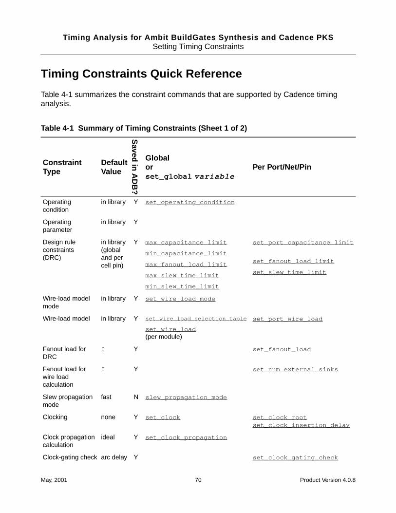
Timing Analysis for Ambit BuildGates Synthesis and Cadence PKSSetting Timing Constraints
Timing Constraints Quick Reference
Table 4-1 summarizes the constraint commands that are supported by Cadence timinganalysis.
Table 4-1 Summary of Timing Constraints (Sheet 1 of 2)
ConstraintType
DefaultValue
Saved in A
DB
?
Globalorset_global variable
Per Port/Net/Pin
Operatingcondition
in library Y set_operating_condition
Operatingparameter
in library Y
Design ruleconstraints(DRC)
in library(globaland percell pin)
Y max_capacitance_limit
min_capacitance_limit
max_fanout_load_limit
max_slew_time_limit
min_slew_time_limit
set_port_capacitance_limit
set_fanout_load_limit
set_slew_time_limit
Wire-load modelmode
in library Y set_wire_load_mode
Wire-load model in library Y set_wire_load_selection_table
set_wire_load(per module)
set_port_wire_load
Fanout load forDRC
0 Y set_fanout_load
Fanout load forwire loadcalculation
0 Y set_num_external_sinks
Slew propagationmode
fast N slew_propagation_mode
Clocking none Y set_clock set_clock_rootset_clock_insertion_delay
Clock propagationcalculation
ideal Y set_clock_propagation
Clock-gating check arc delay Y set_clock_gating_check
May, 2001 70 Product Version 4.0.8
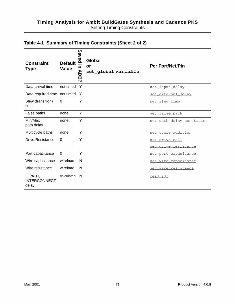
Timing Analysis for Ambit BuildGates Synthesis and Cadence PKSSetting Timing Constraints
Data arrival time not timed Y set_input_delay
Data required time not timed Y set_external_delay
Slew (transition)time
0 Y set_slew_time
False paths none Y set_false_path
Min/Maxpath delay
none Y set_path_delay_constraint
Multicycle paths none Y set_cycle_addition
Drive Resistance 0 Y set_drive_cell
set_drive_resistance
Port capacitance 0 Y set_port_capacitance
Wire capacitance wireload N set_wire_capacitance
Wire resistance wireload N set_wire_resistance
IOPATH,INTERCONNECTdelay
calculated N read_sdf
Table 4-1 Summary of Timing Constraints (Sheet 2 of 2)
ConstraintType
DefaultValue
Saved in A
DB
?
Globalorset_global variable
Per Port/Net/Pin
May, 2001 71 Product Version 4.0.8
Timing Analysis for Ambit BuildGates Synthesis and Cadence PKSSetting Timing Constraints
Setting the Timing Context
Timing context is specified by identifying the top timing module of the design hierarchy.Subsequent commands that assert constraints refer to this timing module.
➤ To set the context for constraint assertions or for analysis, use theset_top_timing_module command. For example:
set_top_timing_module top
The timing analyzer maintains the analysis and constraints pertaining to different timingcontexts. Thus, the set_top_timing_module command can be viewed as a selectionmechanism for timing contexts.
For more information, see Setting the Timing Context for Synthesis on page 119. Also seeset_top_timing_module in the Command Reference for Ambit BuildGatesSynthesis and Cadence PKS.
Specifying Clocks
Timing analysis of sequential circuits is relative to the clock. You must specify one or moreclocks for sequential designs. The most important assertion you can make for correct timinganalysis is the clock definition. Clock information that you can specify includes:
■ Period and waveform
■ Latency (insertion delay)
■ Uncertainty (skew)
■ Gated clock checks
■ Transition time (slew time)
Cadence timing analysis approximates the actual waveform edge as a ramp. Figure 4-1 onpage 73 shows the measurement points for the delays in a clock waveform.
May, 2001 72 Product Version 4.0.8
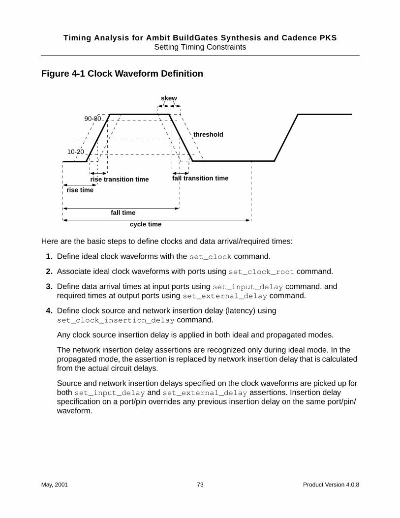
Timing Analysis for Ambit BuildGates Synthesis and Cadence PKSSetting Timing Constraints
Figure 4-1 Clock Waveform Definition
Here are the basic steps to define clocks and data arrival/required times:
1. Define ideal clock waveforms with the set_clock command.
2. Associate ideal clock waveforms with ports using set_clock_root command.
3. Define data arrival times at input ports using set_input_delay command, andrequired times at output ports using set_external_delay command.
4. Define clock source and network insertion delay (latency) usingset_clock_insertion_delay command.
Any clock source insertion delay is applied in both ideal and propagated modes.
The network insertion delay assertions are recognized only during ideal mode. In thepropagated mode, the assertion is replaced by network insertion delay that is calculatedfrom the actual circuit delays.
Source and network insertion delays specified on the clock waveforms are picked up forboth set_input_delay and set_external_delay assertions. Insertion delayspecification on a port/pin overrides any previous insertion delay on the same port/pin/waveform.
rise time
cycle time
fall time
fall transition timerise transition time
skew
threshold
10-20
90-80
May, 2001 73 Product Version 4.0.8
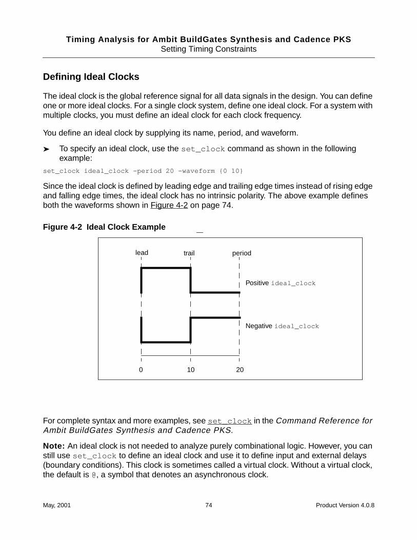
Timing Analysis for Ambit BuildGates Synthesis and Cadence PKSSetting Timing Constraints
Defining Ideal Clocks
The ideal clock is the global reference signal for all data signals in the design. You can defineone or more ideal clocks. For a single clock system, define one ideal clock. For a system withmultiple clocks, you must define an ideal clock for each clock frequency.
You define an ideal clock by supplying its name, period, and waveform.
➤ To specify an ideal clock, use the set_clock command as shown in the followingexample:
set_clock ideal_clock -period 20 -waveform {0 10}
Since the ideal clock is defined by leading edge and trailing edge times instead of rising edgeand falling edge times, the ideal clock has no intrinsic polarity. The above example definesboth the waveforms shown in Figure 4-2 on page 74.
Figure 4-2 Ideal Clock Example
For complete syntax and more examples, see set_clock in the Command Reference forAmbit BuildGates Synthesis and Cadence PKS.
Note: An ideal clock is not needed to analyze purely combinational logic. However, you canstill use set_clock to define an ideal clock and use it to define input and external delays(boundary conditions). This clock is sometimes called a virtual clock. Without a virtual clock,the default is @, a symbol that denotes an asynchronous clock.
Positive ideal_clock
Negative ideal_clock
lead trail period
0 10 20
May, 2001 74 Product Version 4.0.8
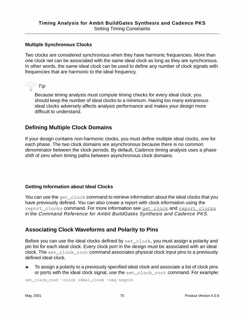
Timing Analysis for Ambit BuildGates Synthesis and Cadence PKSSetting Timing Constraints
Multiple Synchronous Clocks
Two clocks are considered synchronous when they have harmonic frequencies. More thanone clock net can be associated with the same ideal clock as long as they are synchronous.In other words, the same ideal clock can be used to define any number of clock signals withfrequencies that are harmonic to the ideal frequency.
Tip
Because timing analysis must compute timing checks for every ideal clock, youshould keep the number of ideal clocks to a minimum. Having too many extraneousideal clocks adversely affects analysis performance and makes your design moredifficult to understand.
Defining Multiple Clock Domains
If your design contains non-harmonic clocks, you must define multiple ideal clocks, one foreach phase. The two clock domains are asynchronous because there is no commondenominator between the clock periods. By default, Cadence timing analysis uses a phaseshift of zero when timing paths between asynchronous clock domains.
Getting Information about Ideal Clocks
You can use the get_clock command to retrieve information about the ideal clocks that youhave previously defined. You can also create a report with clock information using thereport_clocks command. For more information see get_clock and report_clocksin the Command Reference for Ambit BuildGates Synthesis and Cadence PKS.
Associating Clock Waveforms and Polarity to Pins
Before you can use the ideal clocks defined by set_clock , you must assign a polarity andpin list for each ideal clock. Every clock port in the design must be associated with an idealclock. The set_clock_root command associates physical clock input pins to a previouslydefined ideal clock.
➤ To assign a polarity to a previously specified ideal clock and associate a list of clock pinsor ports with the ideal clock signal, use the set_clock_root command. For example:
set_clock_root -clock ideal_clock -neg negclk
May, 2001 75 Product Version 4.0.8
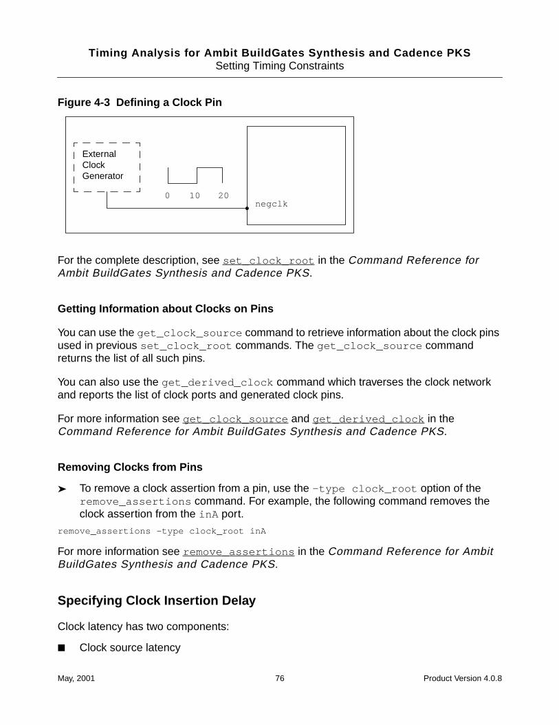
Timing Analysis for Ambit BuildGates Synthesis and Cadence PKSSetting Timing Constraints
Figure 4-3 Defining a Clock Pin
For the complete description, see set_clock_root in the Command Reference forAmbit BuildGates Synthesis and Cadence PKS.
Getting Information about Clocks on Pins
You can use the get_clock_source command to retrieve information about the clock pinsused in previous set_clock_root commands. The get_clock_source commandreturns the list of all such pins.
You can also use the get_derived_clock command which traverses the clock networkand reports the list of clock ports and generated clock pins.
For more information see get_clock_source and get_derived_clock in theCommand Reference for Ambit BuildGates Synthesis and Cadence PKS.
Removing Clocks from Pins
➤ To remove a clock assertion from a pin, use the -type clock_root option of theremove_assertions command. For example, the following command removes theclock assertion from the inA port.
remove_assertions -type clock_root inA
For more information see remove_assertions in the Command Reference for AmbitBuildGates Synthesis and Cadence PKS.
Specifying Clock Insertion Delay
Clock latency has two components:
■ Clock source latency
negclk0 20
ExternalClockGenerator
10
May, 2001 76 Product Version 4.0.8
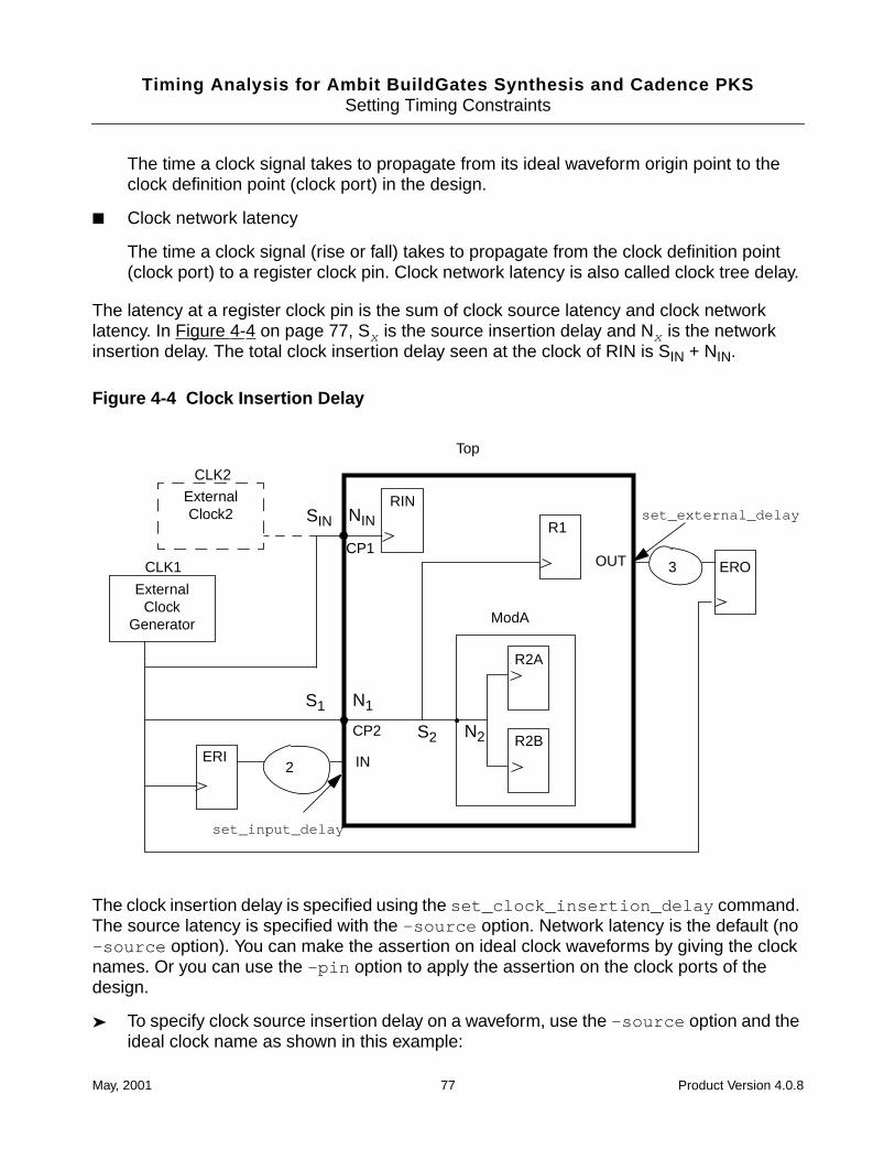
Timing Analysis for Ambit BuildGates Synthesis and Cadence PKSSetting Timing Constraints
The time a clock signal takes to propagate from its ideal waveform origin point to theclock definition point (clock port) in the design.
■ Clock network latency
The time a clock signal (rise or fall) takes to propagate from the clock definition point(clock port) to a register clock pin. Clock network latency is also called clock tree delay.
The latency at a register clock pin is the sum of clock source latency and clock networklatency. In Figure 4-4 on page 77, Sx is the source insertion delay and Nx is the networkinsertion delay. The total clock insertion delay seen at the clock of RIN is SIN + NIN.
Figure 4-4 Clock Insertion Delay
The clock insertion delay is specified using the set_clock_insertion_delay command.The source latency is specified with the -source option. Network latency is the default (no-source option). You can make the assertion on ideal clock waveforms by giving the clocknames. Or you can use the -pin option to apply the assertion on the clock ports of thedesign.
➤ To specify clock source insertion delay on a waveform, use the -source option and theideal clock name as shown in this example:
N2
NIN
ExternalClock
Generator
Top
ModA
S1 N1
S2
SIN
IN
OUT
2
set_input_delay
set_external_delay
3
RIN
R1
R2A
R2BERI
ERO
ExternalClock2
CLK2
CLK1
CP2
CP1
May, 2001 77 Product Version 4.0.8
Timing Analysis for Ambit BuildGates Synthesis and Cadence PKSSetting Timing Constraints
set_clock_insertion_delay -source 2.7 CLK1
➤ To specify clock network insertion delay on a waveform, simply give the clock name, forexample:
set_clock_insertion_delay 4 CLK1
Note: The specification on the port has priority over the waveform assertion.
➤ To specify clock source insertion delay on a clock port or pin, use the -source and -pinoption. The following example sets a value of 2 for S2 in Figure 4-4 on page 77.
set_clock_insertion_delay -source 2 -pin ModA/clk
➤ To specify clock network insertion delay on a clock port or pin, simply give the pin list.The following example sets a value of 5 for N2 in Figure 4-4 on page 77.
set_clock_insertion_delay 5 -pin ModA/clk
The last full specification on the path has priority. Referring back to Figure 4-4 on page 77, Ifboth S2 and N2 are specified, the latency at the clock pins of R2A and R2B is S2 + N2. Ifneither latency is specified at the hierarchical port of ModA, the latency at the clock pins ofR2A and R2B is S1+ N1.
In rare cases, there is more than one ideal clock arriving at a clock port. For instance, inFigure 4-4 on page 77, the clock port CP1 can be reached from both CLK1 and CLK2. In thiscase, you can specify which ideal clock is causing the source latency by using the -clockoption with the -source option.
➤ To specify the clock responsible for the source delay in a multiple clock situation, use the-clock option, for example:
set_clock_insertion_delay -source -clock CLK2 1.0 -pin CP1
Setting Clock Propagation Mode for Analysis
There are two propagation modes for timing analysis, ideal and propagated. Source insertiondelay (Sx ) is considered in both ideal and propagated modes. Network insertion delay (Nx )is only considered in ideal mode. In propagated mode, the asserted network delay is replacedby the actual clock tree delays. In other words, in ideal mode both Sx and Nx are considered.In propagated mode, Nx is replaced by backannotated clock tree data and only the sourceinsertion delay on clock ports is honored.
➤ To analyze your design with clock tree insertion delays set to zero, use the idealargument in the set_clock_propagation command as shown.
set_clock_propagation -ideal
Cadence timing analysis uses ideal clock latency mode by default. You can override thedefault for the current top timing module when you do have layout data.
May, 2001 78 Product Version 4.0.8
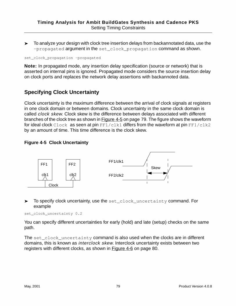
Timing Analysis for Ambit BuildGates Synthesis and Cadence PKSSetting Timing Constraints
➤ To analyze your design with clock tree insertion delays from backannotated data, use the-propagated argument in the set_clock_propagation command as shown.
set_clock_propagation -propagated
Note: In propagated mode, any insertion delay specification (source or network) that isasserted on internal pins is ignored. Propagated mode considers the source insertion delayon clock ports and replaces the network delay assertions with backannoted data.
Specifying Clock Uncertainty
Clock uncertainty is the maximum difference between the arrival of clock signals at registersin one clock domain or between domains. Clock uncertainty in the same clock domain iscalled clock skew. Clock skew is the difference between delays associated with differentbranches of the clock tree as shown in Figure 4-5 on page 79. The figure shows the waveformfor ideal clock Clock as seen at pin FF1/clk1 differs from the waveform at pin FF1/clk2by an amount of time. This time difference is the clock skew.
Figure 4-5 Clock Uncertainty
➤ To specify clock uncertainty, use the set_clock_uncertainty command. Forexample
set_clock_uncertainty 0.2
You can specify different uncertainties for early (hold) and late (setup) checks on the samepath.
The set_clock_uncertainty command is also used when the clocks are in differentdomains, this is known as interclock skew. Interclock uncertainty exists between tworegisters with different clocks, as shown in Figure 4-6 on page 80.
FF2/clk2
FF1/clk1
Skew
Clock
clk2clk1
FF1 FF2
May, 2001 79 Product Version 4.0.8
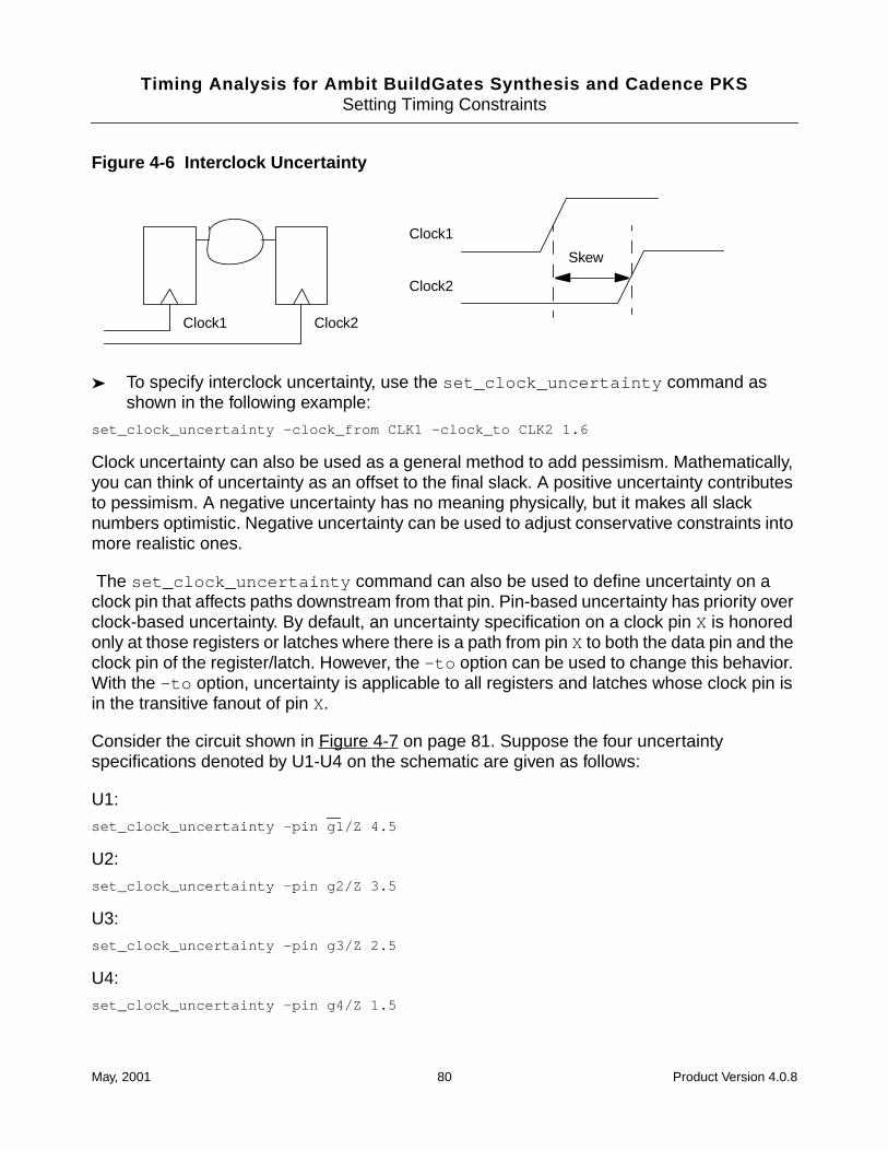
Timing Analysis for Ambit BuildGates Synthesis and Cadence PKSSetting Timing Constraints
Figure 4-6 Interclock Uncertainty
➤ To specify interclock uncertainty, use the set_clock_uncertainty command asshown in the following example:
set_clock_uncertainty -clock_from CLK1 -clock_to CLK2 1.6
Clock uncertainty can also be used as a general method to add pessimism. Mathematically,you can think of uncertainty as an offset to the final slack. A positive uncertainty contributesto pessimism. A negative uncertainty has no meaning physically, but it makes all slacknumbers optimistic. Negative uncertainty can be used to adjust conservative constraints intomore realistic ones.
The set_clock_uncertainty command can also be used to define uncertainty on aclock pin that affects paths downstream from that pin. Pin-based uncertainty has priority overclock-based uncertainty. By default, an uncertainty specification on a clock pin X is honoredonly at those registers or latches where there is a path from pin X to both the data pin and theclock pin of the register/latch. However, the -to option can be used to change this behavior.With the -to option, uncertainty is applicable to all registers and latches whose clock pin isin the transitive fanout of pin X.
Consider the circuit shown in Figure 4-7 on page 81. Suppose the four uncertaintyspecifications denoted by U1-U4 on the schematic are given as follows:
U1:
set_clock_uncertainty -pin g1/Z 4.5
U2:
set_clock_uncertainty -pin g2/Z 3.5
U3:
set_clock_uncertainty -pin g3/Z 2.5
U4:
set_clock_uncertainty -pin g4/Z 1.5
Clock2
Clock1
Skew
Clock1 Clock2
May, 2001 80 Product Version 4.0.8
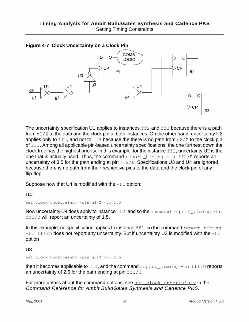
Timing Analysis for Ambit BuildGates Synthesis and Cadence PKSSetting Timing Constraints
Figure 4-7 Clock Uncertainty on a Clock Pin
The uncertainty specification U1 applies to instances ff2 and ff3 because there is a pathfrom g1/Z to the data and the clock pin of both instances. On the other hand, uncertainty U2applies only to ff2 , and not to ff3 because the there is no path from g2/Z to the clock pinof ff3 . Among all applicable pin-based uncertainty specifications, the one furthest down theclock tree has the highest priority. In this example, for the instance ff2 , uncertainty U2 is theone that is actually used. Thus, the command report_timing -to ff2/D reports anuncertainty of 3.5 for the path ending at pin ff2/D . Specifications U3 and U4 are ignoredbecause there is no path from their respective pins to the data and the clock pin of anyflip-flop.
Suppose now that U4 is modified with the -to option:
U4:
set_clock_uncertainty -pin g4/Z -to 1.5
Now uncertainty U4 does apply to instance ff2 , and so the command report_timing -toff2/D will report an uncertainty of 1.5.
In this example, no specification applies to instance ff1 , so the command report_timing-to ff1/D does not report any uncertainty. But if uncertainty U3 is modified with the -tooption
U3:
set_clock_uncertainty -pin g3/Z -to 2.5
then it becomes applicable to ff1 , and the command report_timing -to ff1/D reportsan uncertainty of 2.5 for the path ending at pin ff1/D .
For more details about the command options, see set_clock_uncertainty in theCommand Reference for Ambit BuildGates Synthesis and Cadence PKS.
ff1 ff2
U1 U2
g1 g2
U3
ff3
clkg3 U4
g4
COMBLOGICD Q D Q
D Q
CP CP
CP
May, 2001 81 Product Version 4.0.8
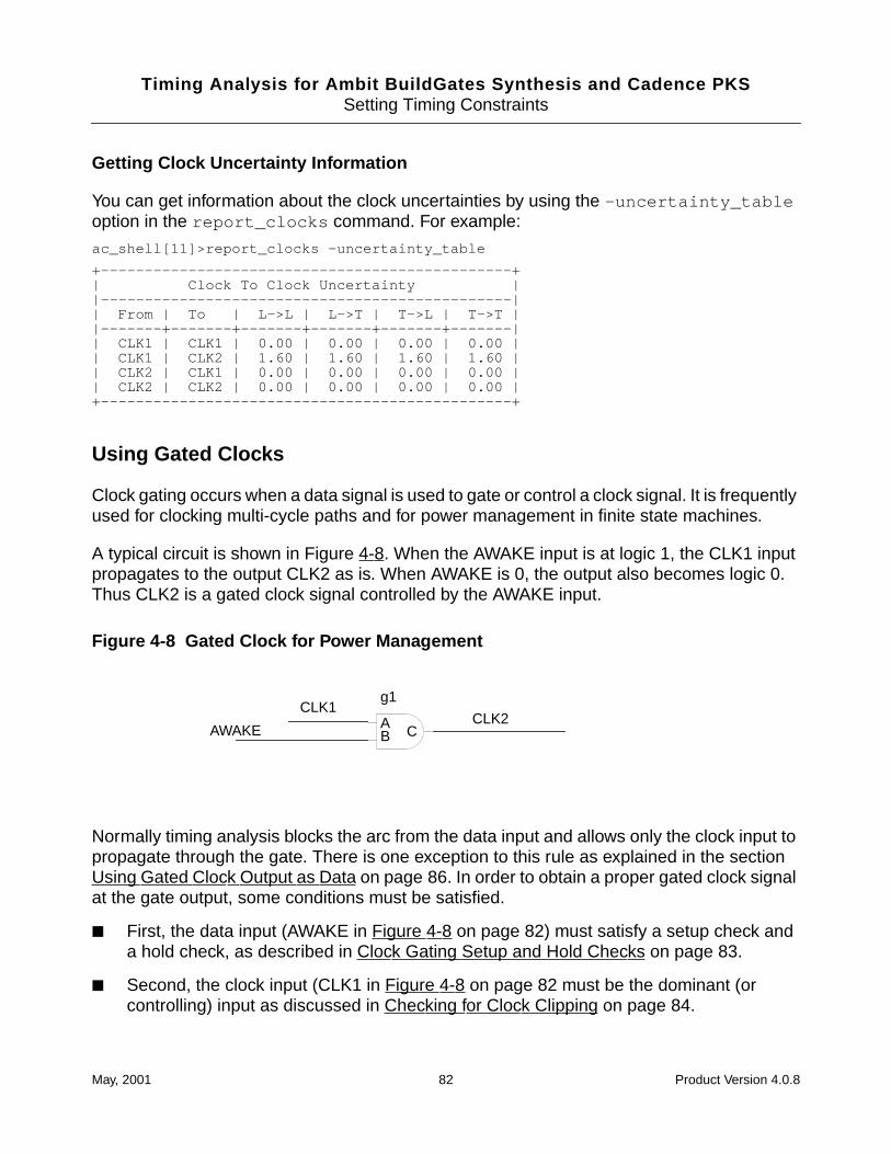
Timing Analysis for Ambit BuildGates Synthesis and Cadence PKSSetting Timing Constraints
Getting Clock Uncertainty Information
You can get information about the clock uncertainties by using the -uncertainty_tableoption in the report_clocks command. For example:
ac_shell[11]>report_clocks -uncertainty_table
+-----------------------------------------------+| Clock To Clock Uncertainty ||-----------------------------------------------|| From | To | L->L | L->T | T->L | T->T ||-------+-------+-------+-------+-------+-------|| CLK1 | CLK1 | 0.00 | 0.00 | 0.00 | 0.00 || CLK1 | CLK2 | 1.60 | 1.60 | 1.60 | 1.60 || CLK2 | CLK1 | 0.00 | 0.00 | 0.00 | 0.00 || CLK2 | CLK2 | 0.00 | 0.00 | 0.00 | 0.00 |+-----------------------------------------------+
Using Gated Clocks
Clock gating occurs when a data signal is used to gate or control a clock signal. It is frequentlyused for clocking multi-cycle paths and for power management in finite state machines.
A typical circuit is shown in Figure 4-8. When the AWAKE input is at logic 1, the CLK1 inputpropagates to the output CLK2 as is. When AWAKE is 0, the output also becomes logic 0.Thus CLK2 is a gated clock signal controlled by the AWAKE input.
Figure 4-8 Gated Clock for Power Management
Normally timing analysis blocks the arc from the data input and allows only the clock input topropagate through the gate. There is one exception to this rule as explained in the sectionUsing Gated Clock Output as Data on page 86. In order to obtain a proper gated clock signalat the gate output, some conditions must be satisfied.
■ First, the data input (AWAKE in Figure 4-8 on page 82) must satisfy a setup check anda hold check, as described in Clock Gating Setup and Hold Checks on page 83.
■ Second, the clock input (CLK1 in Figure 4-8 on page 82 must be the dominant (orcontrolling) input as discussed in Checking for Clock Clipping on page 84.
CLK1
AWAKECLK2A
B C
g1
May, 2001 82 Product Version 4.0.8
Timing Analysis for Ambit BuildGates Synthesis and Cadence PKSSetting Timing Constraints
Procedure to Use a Gated Clock
To use a gated clock in your design, follow these steps:
1. If you expect a DATA pin to be connected to the gated clock output, set the followingglobal:
set_global clock_gating_regardless_of_downstream_logic false
If you expect all pins at the output of the gated clock to be clock pins, you can skip thisstep because the default value of this global is true . For more information. see UsingGated Clock Output as Data on page 86.
2. If you need to change the default setup or hold times of the gate as discussed in ClockGating Setup and Hold Checks on page 83, use the set_clock_gating_checkcommand as illustrated in this example:
set_clock_gating_check -setup 0.55 -pin g1/B
set_clock_gating_check -hold 0.15 -pin g1/B
This sets the gated-clock timing checks to verify that the data input to a gated clock isstable when the clock signal makes its transitions.
3. Before you run timing analysis, check for clock clipping (and other timing errors) byissuing this command:
check_timing
More details about how the checks are performed are given in Checking for ClockClipping on page 84.
Clock Gating Setup and Hold Checks
The setup and hold check are shown as Ia and Ib in Figure 4-9 on page 84. The purpose ofthese checks is to ensure that the data input is stable while the clock input makes itstransitions. A violation of either check implies that the clock input is not properly propagatedto the output.
The setup and hold times are based on the gate delays. In ideal propagation mode, the clocknetwork is assumed to have zero delays, so timing analysis uses zero setup and zero holdtime. In propagated mode, for setup time, the analysis uses the maximum arc delay from thedata pin to the output pin. For hold time, it uses the minimum arc delay from the clock pin tothe output pin. These are default values, you can override them using theset_clock_gating_check command.
May, 2001 83 Product Version 4.0.8
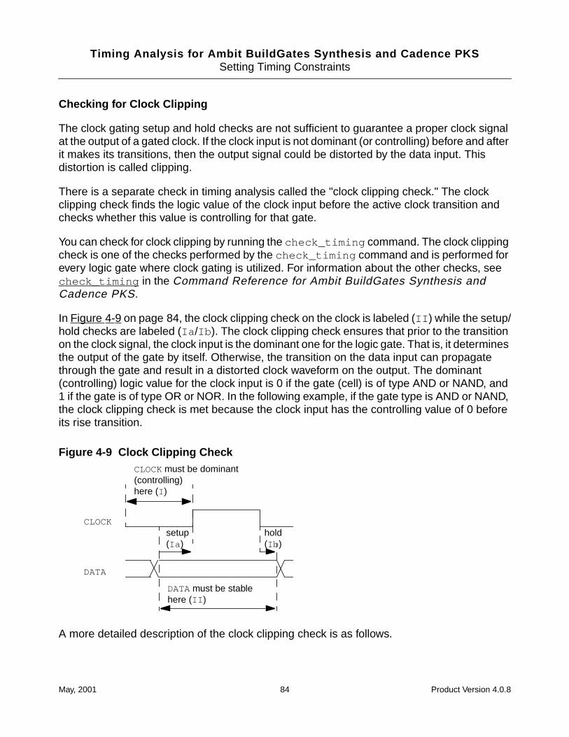
Timing Analysis for Ambit BuildGates Synthesis and Cadence PKSSetting Timing Constraints
Checking for Clock Clipping
The clock gating setup and hold checks are not sufficient to guarantee a proper clock signalat the output of a gated clock. If the clock input is not dominant (or controlling) before and afterit makes its transitions, then the output signal could be distorted by the data input. Thisdistortion is called clipping.
There is a separate check in timing analysis called the "clock clipping check." The clockclipping check finds the logic value of the clock input before the active clock transition andchecks whether this value is controlling for that gate.
You can check for clock clipping by running the check_timing command. The clock clippingcheck is one of the checks performed by the check_timing command and is performed forevery logic gate where clock gating is utilized. For information about the other checks, seecheck_timing in the Command Reference for Ambit BuildGates Synthesis andCadence PKS.
In Figure 4-9 on page 84, the clock clipping check on the clock is labeled (II ) while the setup/hold checks are labeled (Ia /Ib ). The clock clipping check ensures that prior to the transitionon the clock signal, the clock input is the dominant one for the logic gate. That is, it determinesthe output of the gate by itself. Otherwise, the transition on the data input can propagatethrough the gate and result in a distorted clock waveform on the output. The dominant(controlling) logic value for the clock input is 0 if the gate (cell) is of type AND or NAND, and1 if the gate is of type OR or NOR. In the following example, if the gate type is AND or NAND,the clock clipping check is met because the clock input has the controlling value of 0 beforeits rise transition.
Figure 4-9 Clock Clipping Check
A more detailed description of the clock clipping check is as follows.
CLOCK
DATA
DATA must be stablehere (II )
CLOCK must be dominant(controlling)here (I )
setup(Ia )
hold(Ib )
May, 2001 84 Product Version 4.0.8
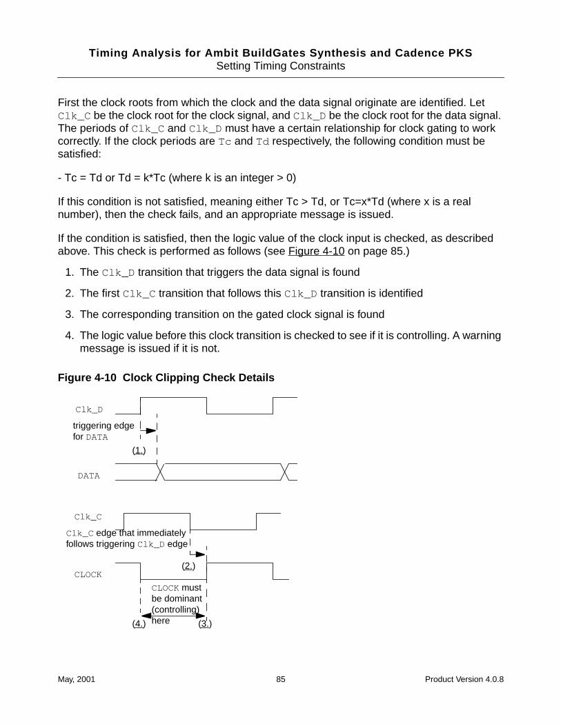
Timing Analysis for Ambit BuildGates Synthesis and Cadence PKSSetting Timing Constraints
First the clock roots from which the clock and the data signal originate are identified. LetClk_C be the clock root for the clock signal, and Clk_D be the clock root for the data signal.The periods of Clk_C and Clk_D must have a certain relationship for clock gating to workcorrectly. If the clock periods are Tc and Td respectively, the following condition must besatisfied:
- Tc = Td or Td = k*Tc (where k is an integer > 0)
If this condition is not satisfied, meaning either Tc > Td, or Tc=x*Td (where x is a realnumber), then the check fails, and an appropriate message is issued.
If the condition is satisfied, then the logic value of the clock input is checked, as describedabove. This check is performed as follows (see Figure 4-10 on page 85.)
1. The Clk_D transition that triggers the data signal is found
2. The first Clk_C transition that follows this Clk_D transition is identified
3. The corresponding transition on the gated clock signal is found
4. The logic value before this clock transition is checked to see if it is controlling. A warningmessage is issued if it is not.
Figure 4-10 Clock Clipping Check Details
CLOCK mustbe dominant(controlling)here
DATA
Clk_D
triggering edgefor DATA
Clk_C
CLOCK
Clk_C edge that immediatelyfollows triggering Clk_D edge
(1.)
(2.)
(3.)(4.)
May, 2001 85 Product Version 4.0.8
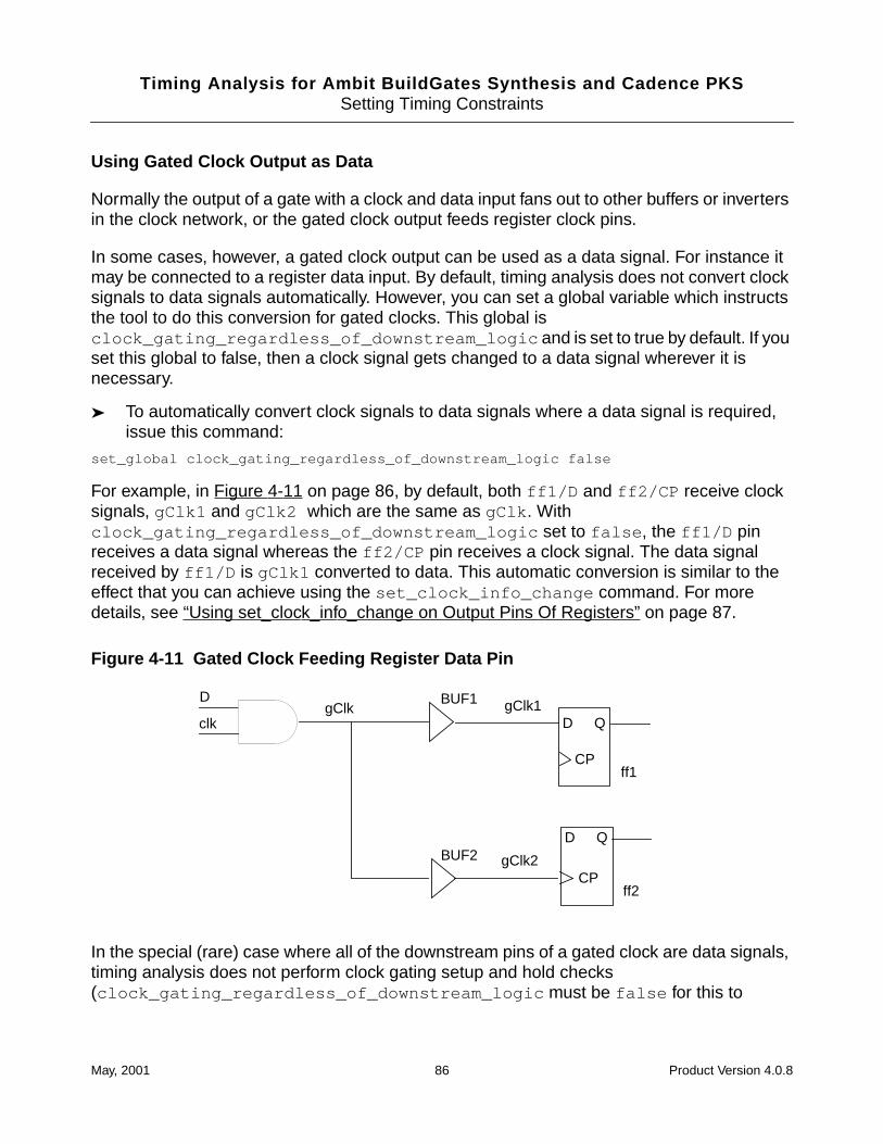
Timing Analysis for Ambit BuildGates Synthesis and Cadence PKSSetting Timing Constraints
Using Gated Clock Output as Data
Normally the output of a gate with a clock and data input fans out to other buffers or invertersin the clock network, or the gated clock output feeds register clock pins.
In some cases, however, a gated clock output can be used as a data signal. For instance itmay be connected to a register data input. By default, timing analysis does not convert clocksignals to data signals automatically. However, you can set a global variable which instructsthe tool to do this conversion for gated clocks. This global isclock_gating_regardless_of_downstream_logic and is set to true by default. If youset this global to false, then a clock signal gets changed to a data signal wherever it isnecessary.
➤ To automatically convert clock signals to data signals where a data signal is required,issue this command:
set_global clock_gating_regardless_of_downstream_logic false
For example, in Figure 4-11 on page 86, by default, both ff1/D and ff2/CP receive clocksignals, gClk1 and gClk2 which are the same as gClk . Withclock_gating_regardless_of_downstream_logic set to false , the ff1/D pinreceives a data signal whereas the ff2/CP pin receives a clock signal. The data signalreceived by ff1/D is gClk1 converted to data. This automatic conversion is similar to theeffect that you can achieve using the set_clock_info_change command. For moredetails, see “Using set_clock_info_change on Output Pins Of Registers” on page 87.
Figure 4-11 Gated Clock Feeding Register Data Pin
In the special (rare) case where all of the downstream pins of a gated clock are data signals,timing analysis does not perform clock gating setup and hold checks(clock_gating_regardless_of_downstream_logic must be false for this to
ff1
gClk
ff2
D BUF1
D Q
D Q
CP
CP
BUF2
clkgClk1
gClk2
May, 2001 86 Product Version 4.0.8
Timing Analysis for Ambit BuildGates Synthesis and Cadence PKSSetting Timing Constraints
happen.) The arc from the data input is not blocked either. The clock signal, which isconverted to data, as well as the data signal propagated through the gate in this case.
Using Derived Clocks
Derived clocks are generally seen in frequency dividers as discussed in “Usingset_clock_info_change on Output Pins Of Registers.”
Using set_clock_info_change on Output Pins Of Registers
This section describes how the rising and the falling edges of the final clock signal arecomputed when the output of a register is defined as a clock
Important
In releases prior to 2.2, using the set_clock_info_change command requiredyou to specify set_cycle_addition with the clock edge (rising or falling)adjustment for both late and early modes. In 2.2 and later releases, you only needto specify set_clock_info_change. The set_clock_info_changecommand automatically does the edge adjustment, without the use ofset_cycle_addition command, whenever data is converted to clock.
The calculations are done as follows:
■ RAold
The arrival time of the rising edge of the signal arriving at the pin before clock infochange.
■ FAold
The arrival time of the falling signal arriving at the pin before clock info change.
If set_clock_info_change assertion is put on the output pin of a flip-flop, then in the idealclock propagation case, rising and falling arrival times at output pin Qcorrespond to clk ->Qrising and clk ->Q falling delays.
If the -pos option of set_clock_info_change is used, for example
set_clock_info_change -clock CLOCK -pos U1/Q
Where CLOCK is the ideal clock for the clk pin of the flip-flop. The rising and falling clockedges of the resulting clock are computed as follows:
May, 2001 87 Product Version 4.0.8
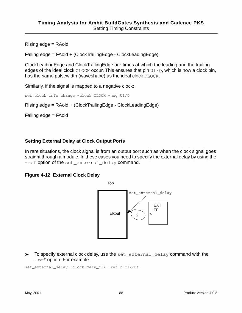
Timing Analysis for Ambit BuildGates Synthesis and Cadence PKSSetting Timing Constraints
Rising edge = RAold
Falling edge = FAold + (ClockTrailingEdge - ClockLeadingEdge)
ClockLeadingEdge and ClockTrailingEdge are times at which the leading and the trailingedges of the ideal clock CLOCKoccur. This ensures that pin U1/Q, which is now a clock pin,has the same pulsewidth (waveshape) as the ideal clock CLOCK.
Similarly, if the signal is mapped to a negative clock:
set_clock_info_change -clock CLOCK -neg U1/Q
Rising edge = RAold + (ClockTrailingEdge - ClockLeadingEdge)
Falling edge = FAold
Setting External Delay at Clock Output Ports
In rare situations, the clock signal is from an output port such as when the clock signal goesstraight through a module. In these cases you need to specify the external delay by using the-ref option of the set_external_delay command.
Figure 4-12 External Clock Delay
➤ To specify external clock delay, use the set_external_delay command with the-ref option. For example
set_external_delay -clock main_clk -ref 2 clkout
Top
clkout
set_external_delay
2
EXTFF
May, 2001 88 Product Version 4.0.8
Timing Analysis for Ambit BuildGates Synthesis and Cadence PKSSetting Timing Constraints
This means that the assertion is set on a clock network. The default (-sig ) sets theassertion on a data signal. For more information, see set_external_delay inCommand Reference for Ambit BuildGates Synthesis and Cadence PKS.
Specifying Operating Conditions
The technology library contains timing data about all the cells at nominal voltage, temperatureand process. You must consider how the variations in these conditions affect factors such asresistance, capacitance, propagation delay, and so on. In turn, these factors affect the cellselection during the synthesis process. Therefore, it is important that the operating conditionbe specified for a particular synthesis run to approximate the real circumstances under whichthe design will be used.
Each technology library contains one or more operating conditions. Each operating conditionis identified by name and specifes the process, voltage, and temperature. This information isused in calculating accurate cell delays from the nominal cell delays and the k-factors (alsocalled derating factors) using either a linear model or non-linear model.
➤ To specify the operating conditions for the design, select the named operating conditionfrom the library with the set_operating_condition command. For example:
set_operating_condition wc_mil
The set_operating_parameter command overrides the parameter value from thedefault operating condition of the technology library. It also overrides the parameter valuefrom any operating condition you previously selected with the set_operating_conditioncommand.
➤ To individually set the operating parameters (process, temperature, or voltage) for thedesign, use the set_operating_parameter command. For example:
set_operating_parameter -voltage 3.3 -typ
For the complete usage, see these commands in the Command Reference for AmbitBuildGates Synthesis and Cadence PKS:
set_operating_condition
set_operating_parameter
Specifying Wire Loads
The delay information in the technology library applies to the timing arcs from input ports tooutput ports of each cell and the wire delays. The cell delays and the wire delays are
May, 2001 89 Product Version 4.0.8
Timing Analysis for Ambit BuildGates Synthesis and Cadence PKSSetting Timing Constraints
expressed as a function of the physical characteristics of the nets in the design such as wirecapacitance and wire resistance. In order to perform meaningful analysis before a physicallayout exists, these parameters must be estimated. These estimates are derived from themodels called wire load models.
A wire load model is a function that uses the fanout count of a net and estimates itscapacitance and resistance. A technology library contains different wire load models that arepre-computed based on the analysis of several designs differing in area. Typically, thetechnology libraries have area lookup tables containing the wire load model for a given cellarea. The library has a default wire load selection table that specifies which table is used, butyou can override it.
➤ To override the default wire-load selection table, use the set_wire_load_selection_tablecommand. For example:
Additionally, the floorplanning tools may determine a specific wire load model for a designbased on an initial physical design. The wire load models generated from floorplanning canbe read in using read_library_update command.
Wire Load Model Selection
Figure 4-13 on page 91 provides a flow chart of the algorithm used for selecting a wire loadmodel for a net.
May, 2001 90 Product Version 4.0.8
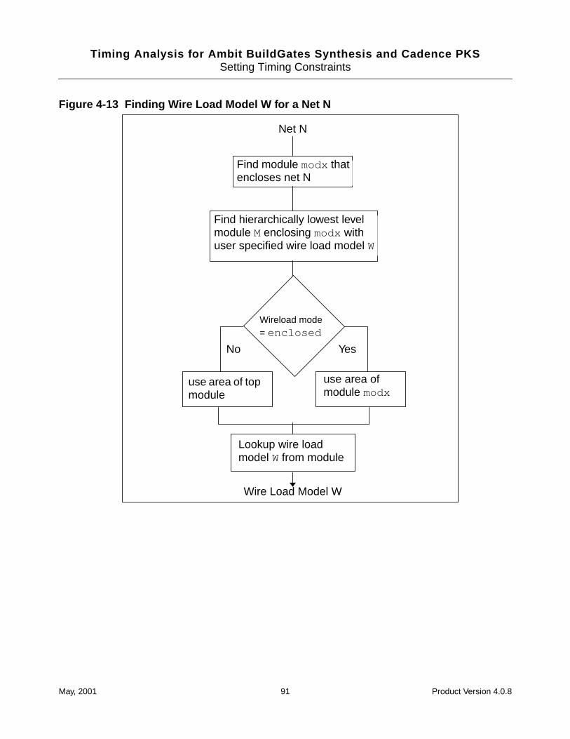
Timing Analysis for Ambit BuildGates Synthesis and Cadence PKSSetting Timing Constraints
Figure 4-13 Finding Wire Load Model W for a Net N
Find module modx thatencloses net N
Find hierarchically lowest levelmodule M enclosing modx withuser specified wire load model W
use area of topmodule
use area ofmodule modx
Lookup wire loadmodel W from module
Net N
Wire Load Model W
YesNo
Wireload mode= enclosed
May, 2001 91 Product Version 4.0.8
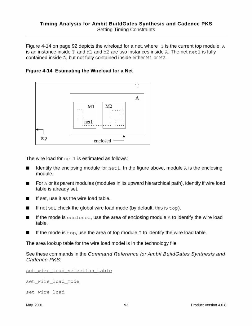
Timing Analysis for Ambit BuildGates Synthesis and Cadence PKSSetting Timing Constraints
Figure 4-14 on page 92 depicts the wireload for a net, where T is the current top module, Ais an instance inside T, and M1 and M2 are two instances inside A. The net net1 is fullycontained inside A, but not fully contained inside either M1 or M2.
Figure 4-14 Estimating the Wireload for a Net
The wire load for net1 is estimated as follows:
■ Identify the enclosing module for net1 . In the figure above, module A is the enclosingmodule.
■ For A or its parent modules (modules in its upward hierarchical path), identify if wire loadtable is already set.
■ If set, use it as the wire load table.
■ If not set, check the global wire load mode (by default, this is top ).
■ If the mode is enclosed , use the area of enclosing module A to identify the wire loadtable.
■ If the mode is top , use the area of top module T to identify the wire load table.
The area lookup table for the wire load model is in the technology file.
See these commands in the Command Reference for Ambit BuildGates Synthesis andCadence PKS:
set_wire_load_selection_table
set_wire_load_mode
set_wire_load
A
M1 M2
net1
T
enclosedtop
May, 2001 92 Product Version 4.0.8
Timing Analysis for Ambit BuildGates Synthesis and Cadence PKSSetting Timing Constraints
set_port_wire_load
read_library_update
Specifying Boundary Conditions
➤ To specify the arrival time for data input ports with respect to an ideal clock, use theset_input_delay command. For example
set_input_delay -clock CLK1 2 IN.
The input delay given in this command corresponds to the delay through logic that is drivenby the flip-flop triggered by specified ideal clock (see Figure 4-4 on page 77).
➤ To specify the arrival time for output ports with respect to an ideal clock, use theset_external_delay command as shown in this example
set_external_delay -clock CLK1 3 OUT
The output delay given in this command corresponds to the delay though logic that drives theflip-flop triggered by the specified ideal clock (see Figure 4-4 on page 77).
The advantage of using these commands is that changes in the clock definition do not requirechanging the data arrival or required times. For instance, the (source) clock insertion delaysfor the ideal clock are automatically taken into account, without having to manually changethe arrival or required times.
For more information, see the command syntax in the Command Reference for AmbitBuildGates Synthesis and Cadence PKS:
set_input_delay
set_external_delay
Specifying Slew Rates
Slew rate is a measure of the slope of an arriving signal. Slew time represents the time it takesfor a signal to change from low (high) level to high (low) level. This change is measuredbetween two predefined thresholds. Figure 4-15 on page 94 shows a lower threshold of 20%and upper threshold of 80%.
May, 2001 93 Product Version 4.0.8
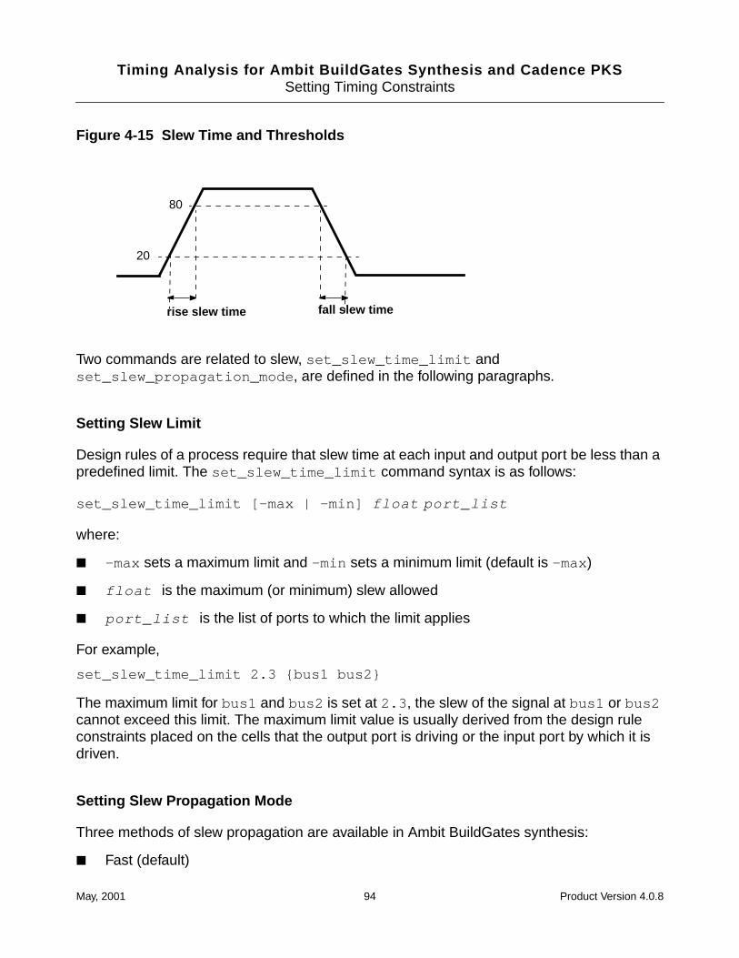
Timing Analysis for Ambit BuildGates Synthesis and Cadence PKSSetting Timing Constraints
Figure 4-15 Slew Time and Thresholds
Two commands are related to slew, set_slew_time_limit andset_slew_propagation_mode , are defined in the following paragraphs.
Setting Slew Limit
Design rules of a process require that slew time at each input and output port be less than apredefined limit. The set_slew_time_limit command syntax is as follows:
set_slew_time_limit [-max | -min] float port_list
where:
■ -max sets a maximum limit and -min sets a minimum limit (default is -max )
■ float is the maximum (or minimum) slew allowed
■ port_list is the list of ports to which the limit applies
For example,
set_slew_time_limit 2.3 {bus1 bus2}
The maximum limit for bus1 and bus2 is set at 2.3 , the slew of the signal at bus1 or bus2cannot exceed this limit. The maximum limit value is usually derived from the design ruleconstraints placed on the cells that the output port is driving or the input port by which it isdriven.
Setting Slew Propagation Mode
Three methods of slew propagation are available in Ambit BuildGates synthesis:
■ Fast (default)
fall slew timerise slew time
20
80
May, 2001 94 Product Version 4.0.8
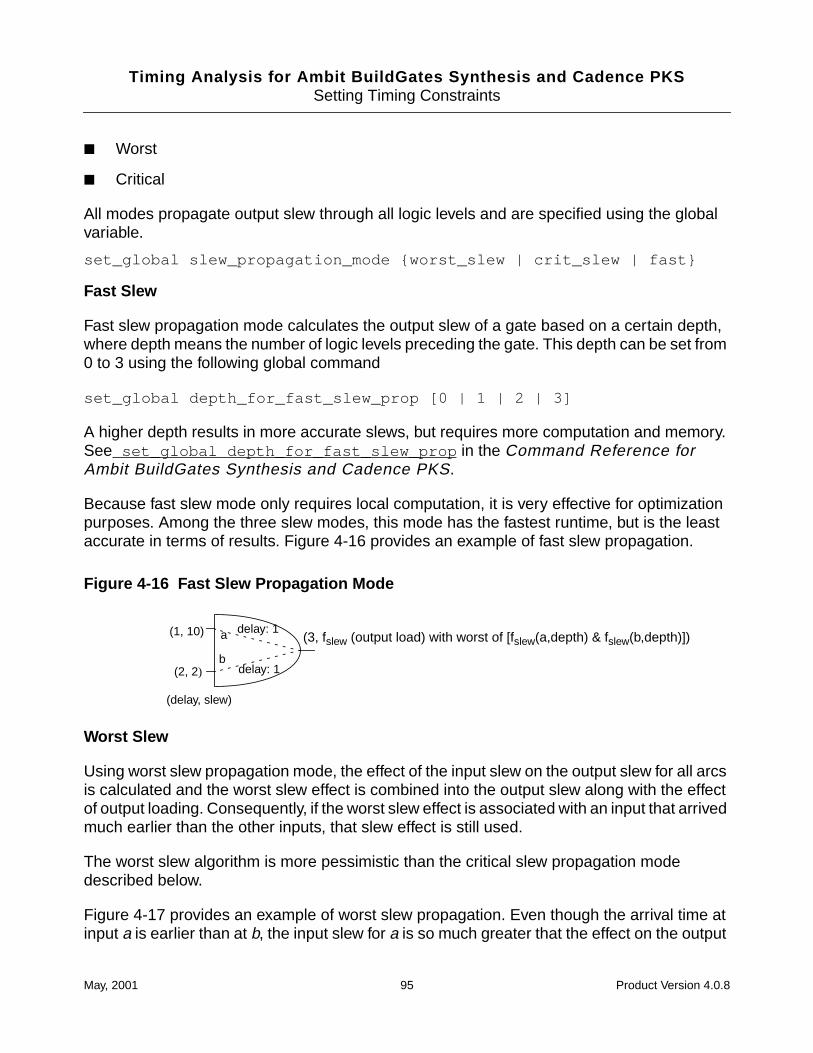
Timing Analysis for Ambit BuildGates Synthesis and Cadence PKSSetting Timing Constraints
■ Worst
■ Critical
All modes propagate output slew through all logic levels and are specified using the globalvariable.
set_global slew_propagation_mode {worst_slew | crit_slew | fast}
Fast Slew
Fast slew propagation mode calculates the output slew of a gate based on a certain depth,where depth means the number of logic levels preceding the gate. This depth can be set from0 to 3 using the following global command
set_global depth_for_fast_slew_prop [0 | 1 | 2 | 3]
A higher depth results in more accurate slews, but requires more computation and memory.See set_global depth_for_fast_slew_prop in the Command Reference forAmbit BuildGates Synthesis and Cadence PKS.
Because fast slew mode only requires local computation, it is very effective for optimizationpurposes. Among the three slew modes, this mode has the fastest runtime, but is the leastaccurate in terms of results. Figure 4-16 provides an example of fast slew propagation.
Figure 4-16 Fast Slew Propagation Mode
Worst Slew
Using worst slew propagation mode, the effect of the input slew on the output slew for all arcsis calculated and the worst slew effect is combined into the output slew along with the effectof output loading. Consequently, if the worst slew effect is associated with an input that arrivedmuch earlier than the other inputs, that slew effect is still used.
The worst slew algorithm is more pessimistic than the critical slew propagation modedescribed below.
Figure 4-17 provides an example of worst slew propagation. Even though the arrival time atinput a is earlier than at b, the input slew for a is so much greater that the effect on the output
(3, fslew (output load) with worst of [fslew(a,depth) & fslew(b,depth)])(1, 10)
(2, 2)
(delay, slew)
delay: 1
delay: 1
a
b
May, 2001 95 Product Version 4.0.8
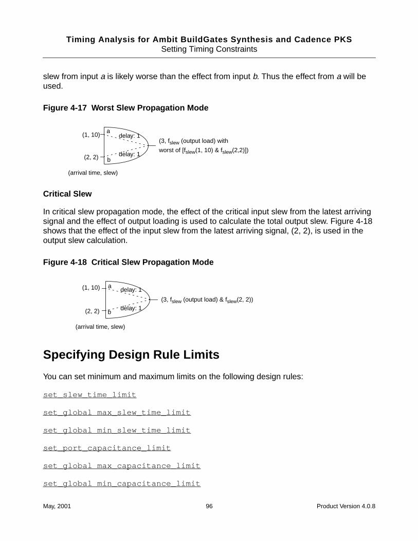
Timing Analysis for Ambit BuildGates Synthesis and Cadence PKSSetting Timing Constraints
slew from input a is likely worse than the effect from input b. Thus the effect from a will beused.
Figure 4-17 Worst Slew Propagation Mode
Critical Slew
In critical slew propagation mode, the effect of the critical input slew from the latest arrivingsignal and the effect of output loading is used to calculate the total output slew. Figure 4-18shows that the effect of the input slew from the latest arriving signal, (2, 2), is used in theoutput slew calculation.
Figure 4-18 Critical Slew Propagation Mode
Specifying Design Rule Limits
You can set minimum and maximum limits on the following design rules:
set_slew_time_limit
set_global max_slew_time_limit
set_global min_slew_time_limit
set_port_capacitance_limit
set_global max_capacitance_limit
set_global min_capacitance_limit
(1, 10)
(2, 2)
(arrival time, slew)
delay: 1
delay: 1
a
b
(3, fslew (output load) with
worst of [fslew(1, 10) & fslew(2,2)])
(1, 10)
(2, 2)
(arrival time, slew)
delay: 1
delay: 1
a
b
(3, fslew (output load) & fslew(2, 2))
May, 2001 96 Product Version 4.0.8
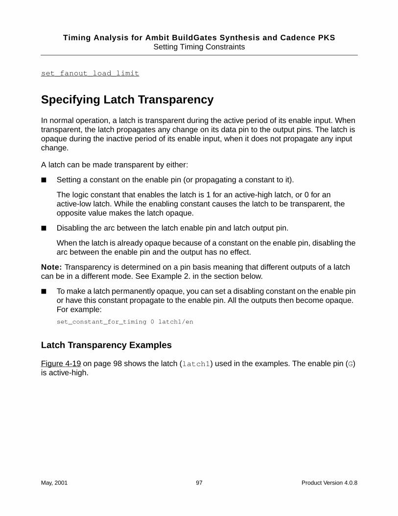
Timing Analysis for Ambit BuildGates Synthesis and Cadence PKSSetting Timing Constraints
set_fanout_load_limit
Specifying Latch Transparency
In normal operation, a latch is transparent during the active period of its enable input. Whentransparent, the latch propagates any change on its data pin to the output pins. The latch isopaque during the inactive period of its enable input, when it does not propagate any inputchange.
A latch can be made transparent by either:
■ Setting a constant on the enable pin (or propagating a constant to it).
The logic constant that enables the latch is 1 for an active-high latch, or 0 for anactive-low latch. While the enabling constant causes the latch to be transparent, theopposite value makes the latch opaque.
■ Disabling the arc between the latch enable pin and latch output pin.
When the latch is already opaque because of a constant on the enable pin, disabling thearc between the enable pin and the output has no effect.
Note: Transparency is determined on a pin basis meaning that different outputs of a latchcan be in a different mode. See Example 2. in the section below.
■ To make a latch permanently opaque, you can set a disabling constant on the enable pinor have this constant propagate to the enable pin. All the outputs then become opaque.For example:
set_constant_for_timing 0 latch1/en
Latch Transparency Examples
Figure 4-19 on page 98 shows the latch (latch1 ) used in the examples. The enable pin (G)is active-high.
May, 2001 97 Product Version 4.0.8
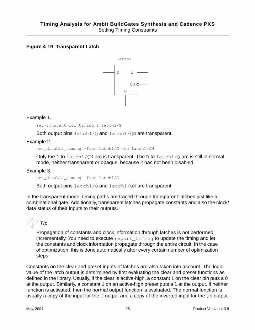
Timing Analysis for Ambit BuildGates Synthesis and Cadence PKSSetting Timing Constraints
Figure 4-19 Transparent Latch
Example 1.
set_constant_for_timing 1 latch1/G
Both output pins latch1/Q and latch1/QN are transparent.
Example 2.set_disable_timing -from latch1/G -to latch1/QN
Only the D to latch1/QN arc is transparent. The D to latch1/Q arc is still in normalmode, neither transparent or opaque, because it has not been disabled.
Example 3.set_disable_timing -from latch1/G
Both output pins latch1/Q and latch1/QN are transparent.
In the transparent mode, timing paths are traced through transparent latches just like acombinational gate. Additionally, transparent latches propagate constants and also the clock/data status of their inputs to their outputs.
Tip
Propagation of constants and clock information through latches is not performedincrementally. You need to execute report_timing to update the timing and letthe constants and clock information propagate through the entire circuit. In the caseof optimization, this is done automatically after every certain number of optimizationsteps.
Constants on the clear and preset inputs of latches are also taken into account. The logicvalue of the latch output is determined by first evaluating the clear and preset functions asdefined in the library. Usually, if the clear is active-high, a constant 1 on the clear pin puts a 0at the output. Similarly, a constant 1 on an active-high preset puts a 1 at the output. If neitherfunction is activated, then the normal output function is evaluated. The normal function isusually a copy of the input for the Qoutput and a copy of the inverted input for the QNoutput.
latch1
D Q
QN
G
May, 2001 98 Product Version 4.0.8

Timing Analysis for Ambit BuildGates Synthesis and Cadence PKSSetting Timing Constraints
May, 2001 99 Product Version 4.0.8

Timing Analysis for Ambit BuildGates Synthesis and Cadence PKSSetting Timing Constraints
May, 2001 100 Product Version 4.0.8
Timing Analysis for Ambit BuildGates Synthesis and Cadence PKS
5Linking Physical Design Information
This chapter describes the exchange of information between the logical and physical designenvironments in Ambit® BuildGates® synthesis. This chapter assumes you have somefamiliarity with physical design tools and design processes.
This chapter contains the following information:
■ Exchanging Physical Design Data on page 102
■ The Generic Synthesis and Timing Task Flow on page 103
■ Generating SDF Constraint Files on page 107
■ Backannotation Support on page 108
■ Reading SDF Files on page 109
■ Reading Net Parasitic Files on page 109
■ The Recommended IPO Approach on page 111
■ Physical Design Exchange Format (PDEF) Flow on page 112
May, 2001 101 Product Version 4.0.8
Timing Analysis for Ambit BuildGates Synthesis and Cadence PKSLinking Physical Design Information
Exchanging Physical Design Data
The exchange of physical design information is key to achieving timing convergence forhigh-performance deep-submicron designs.
An optimal methodology for achieving design convergence includes the ability to exchangebidirectional information between the synthesis environment and the physical design tools(floorplanners, place and route tools). Ideally, there is a mechanism for feeding timingconstraints forward from the synthesis environment (front-end) to the physical design tools(back-end). Likewise, the back-end physical design tools must be able to extract cell andinterconnect delay information, net parasitics, and cell placement information for use in thefront-end design tools.
As the name implies, Cadence® physically knowledgeable synthesis (PKS) has a tighter linkwith physical data than Ambit BuildGates synthesis. This chapter discusses the exchange ofphysical data within Ambit BuildGates synthesis. If you have a license for PKS, you shouldalso read the “PKS Design Flow” chapter in the PKS User Guide.
Forward Annotation
In Ambit BuildGates synthesis you pass the timing constraints to the back-end physicaldesign tools through the use of a Standard Delay Format (SDF) file. The SDF file ispath-based and represents the timing requirements that you specified by setting constraintsas discussed in Chapter 4, “Setting Timing Constraints.”. The SDF file is used by theback-end physical design tools to guide cell placement and routing.
Note: Some back-end tools require constraints to be in a General Constraint Format (GCF)file instead of an SDF file. See Appendix B, “Generating GCF Files” for more information.
Backannotation
The physical design tools extract the following information:
■ Cell and interconnect delays
Calculated by an external delay calculator and written to an SDF file. Ideally the delaycalculator has knowledge of the physical circuit topology. The delay calculator uses wireload estimations in the absence of actual physical data.
■ Net parasitics
Extracted from the physical design database as SPF or SPEF files and annotated on thenets.
May, 2001 102 Product Version 4.0.8
Timing Analysis for Ambit BuildGates Synthesis and Cadence PKSLinking Physical Design Information
■ Cell placement information in DEF format can be backannotated into Cadence physicallyknowledgeable synthesis (PKS).
The Generic Synthesis and Timing Task Flow
In order to achieve timing convergence, synthesis must be coupled with timing-drivenoptimization using data extracted from the physical design environment. The goal is to reducethe number of place and route iterations by incorporating place and route data (or estimateddata) into the synthesis environment. Figure 5-1 on page 104 shows how Ambit BuildGatessynthesis can be coupled with the physical design tools.
A somewhat similar task flow exists within Envisia Physically Knowledgeable Synthesis(PKS). The major exceptions being that initial placement takes place within PKS beforeoptimization. And PKS uses Steiner tree routing algorithms to estimate the interconnectdelays. The physical information is available earlier in the design cycle which reduces thenumber of timing analysis iterations. PKS provides closer correlation between pre- andpost-route timing than traditional methods. If you have a PKS license, refer to the“Conventional Synthesis Limitations” chapter in the PKS User Guide.
May, 2001 103 Product Version 4.0.8
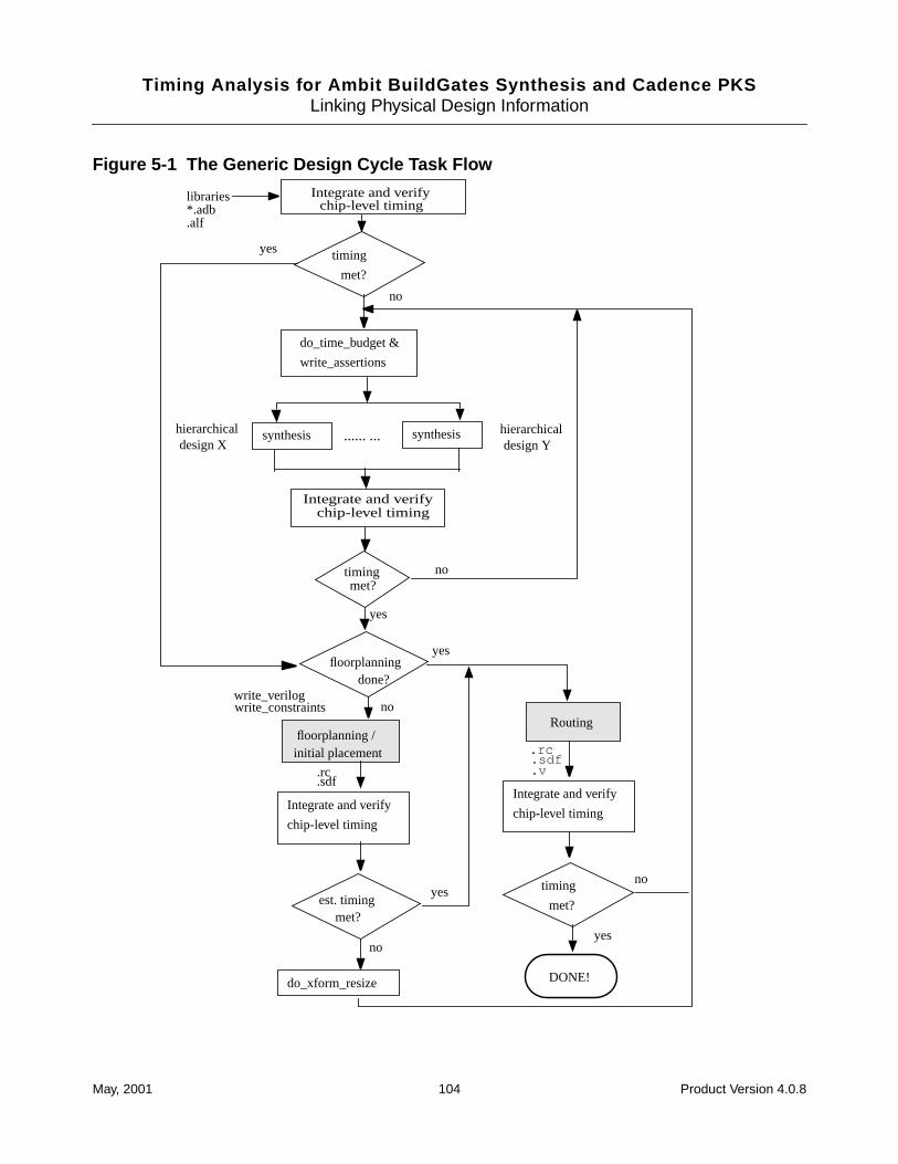
Timing Analysis for Ambit BuildGates Synthesis and Cadence PKSLinking Physical Design Information
Figure 5-1 The Generic Design Cycle Task Flow
synthesis hierarchicalhierarchical
Integrate and verifychip-level timing
timing met?
do_time_budget &
write_assertions
no
floorplanning /
yes
write_constraintswrite_verilog
design X design Y
initial placement .rc.sdf
Routing
yes
Integrate and verifychip-level timing
timing
met?
no
Integrate and verify
chip-level timing
est. timing met?
no
yes
.rc
.sdf
floorplanningdone?
no
yes
do_xform_resize
.v
no
Integrate and verify
chip-level timing
timing
met?
yes
DONE!
synthesis ...... ...
libraries*.adb.alf
May, 2001 104 Product Version 4.0.8
Timing Analysis for Ambit BuildGates Synthesis and Cadence PKSLinking Physical Design Information
Integrate Chip-Level Timing
The initial full-chip design integration should be done in a fashion that best suits your computebandwidth and target methodology. The recommended approach is to use the integrated timebudgeting feature (do_time_budget ) at the top level to derive constraint information for thesub-designs (write_assertions ) and then use hierarchical synthesis while building thosesub-designs in parallel.For additional information, refer to “Bottom-Up-Top-DownMethodology” on page 23 in Chapter 2, “Choosing a Methodology.”
Verify Chip-level Timing
The initial design database is iterated until it is “timing-clean.” This is accomplished by usingestimated wire-load models (available from the silicon vendor). Different design teams havedifferent definitions of a timing-clean database for initial layout. Some design teams requirethat the initial synthesis meets timing while overconstraining the clock period by as much as10-20%. While this approach may reduce the number of failing paths in post-layout timinganalysis, its primary downside is that it does not allow the design to push the technology toits performance limit.
Initial Floorplanning
The ability to accurately model block-level interconnect early in the design cycle is animportant step towards achieving timing convergence. Intramodule nets typically do notcorrelate well with the statistical data that vendors use to derive the wire-load models in theirlibraries. The floorplanning tools can generally be run early in the design cycle, prior to theavailability of a gate-level netlist. The output of the floorplanning tool is either a wire-loadmodel derived from the placement or an estimate of net parasitics for the block-levelinterconnect.
Once timing is achieved using estimated delays, the netlist and the SDF file are forwarded tothe physical design tools.
Final Floorplanning and Placement
Once the design is "timing-clean," final floorplanning is typically performed followed bytiming-driven placement, which uses the SDF path-based constraints file generated by thesynthesis environment.
May, 2001 105 Product Version 4.0.8
Timing Analysis for Ambit BuildGates Synthesis and Cadence PKSLinking Physical Design Information
Post Placement Timing Analysis
After a couple of iterations through the physical design tool, it is recommended to verify timingon the placed design. Physical design tools generally have the ability to extract the SDF fileand net parasitic information necessary for BuildGates synthesis. Performing static timinganalysis after placement lets you fix timing problems prior to expending computing resourceson routing. The newly generated SDF and net parasitic information provide more realistictiming numbers. If any timing problems do surface at this point, it may be possible to performa quick incremental optimization to correct it.
Important
To ensure that drivers of global nets are sized appropriately, perform a resizingtransform on the complete design prior to extracting time-budgeted constraintinformation. See do_xform_resize in the Command Reference for AmbitBuildGates Synthesis and Cadence PKS
The flow proceeds until no timing problems are found during the chip-level timing check.
Post Final Route Timing Analysis
So far you have used estimated net delays and parasitics as specified by the floorplanning orthe placement tool. Once the design meets post placement timing, it is ready for engineeringchange order (ECO) placement and final routing.
After final routing, usually a detailed parasitic file is used to generate an accurate SDF file.This SDF file is used to perform static timing analysis. You may also need to input a gate-levelnetlist as extracted from the physical design tools if any modifications to the netlist were madein the back-end during scan-chain routing, clock-tree generation or synthesis. AmbitBuildGates synthesis does not require any special control to support an ECO process. Youhave complete control to selectively reoptimize specific modules and to preservebackannotated timing wherever possible in the design database. If the design does not meettiming, you must repeat the whole flow.
There may be several iterations before timing is met for the design. All these iterations causedelays in the project. At smaller geometries (0.25 microns or less) there is a chance that thedesign never converges on required timing.
Cadence physically knowledgeable synthesis (PKS) technology is the next-evolution ofsynthesis to address the sensitive issues that the user community faces as technologyprogresses into deep submicron and design sizes increase. The goal of PKS is to provide apath to achieve the best performance from silicon in a convergent fashion. For moreinformation on PKS, see the PKS User Guide.
May, 2001 106 Product Version 4.0.8
Timing Analysis for Ambit BuildGates Synthesis and Cadence PKSLinking Physical Design Information
Generating SDF Constraint Files
After you have specified the constraints for your design as discussed in Chapter 4, “SettingTiming Constraints”, you can generate an SDF file to pass the path constraints to downstreamtools that read SDF. Cadence timing analysis supports the generation of SDF path constraintsthrough the use of the write_constraints command. The output of this command is apath constraints file which includes every path in the design that has a timing constraintassociated with it.
Important
The data written out to the SDF file created by write_constraints is the datayou specified as your target timing goals (constraints), not the actual path delay astimed by Cadence timing analysis.
➤ To generate the SDF constraint file use the write_constraints command as shownin the following example:
write_constraints my_constraints.sdf
For the complete syntax, see write_constraints in the Command Reference forAmbit BuildGates Synthesis and Cadence PKS.
Sample SDF Constraint File
Here is an example of the SDF constraint file (my_constraints.sdf ) created by the abovewrite_constraints command:
( DELAYFILE
( SDFVERSION “2.1” )
( DESIGN “design_name” )
( DATE “date” )
( VENDOR “Cadence Design Systems, Inc.” )
( PROGRAM “Envisia Synthesis” )
( VERSION “1.2” )
( DIVIDER / )
( VOLTAGE 5.00:: )
( TEMPRATURE 25.00:: )
( TIMESCALE 1ns )
( CELL
( CELLTYPE tst_buffer )
( INSTANCE )
( TIMINGCHECK
May, 2001 107 Product Version 4.0.8
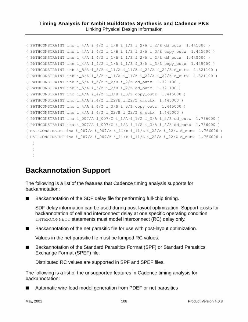
Timing Analysis for Ambit BuildGates Synthesis and Cadence PKSLinking Physical Design Information
( PATHCONSTRAINT inc i_4/A i_4/Z i_1/B i_1/Z i_2/A i_2/Z dd_outz 1.445000 )
( PATHCONSTRAINT inc i_4/A i_4/Z i_1/B i_1/Z i_3/A i_3/Z copy_outz 1.445000 )
( PATHCONSTRAINT inc i_4/A i_4/Z i_1/B i_1/Z i_2/A i_2/Z dd_outz 1.445000 )
( PATHCONSTRAINT inc i_4/A i_4/Z i_1/B i_1/Z i_3/A i_3/Z copy_outz 1.445000 )
( PATHCONSTRAINT inb i_5/A i_5/Z i_11/A i_11/Z i_22/A i_22/Z d_outx 1.321100 )
( PATHCONSTRAINT inb i_5/A i_5/Z i_11/A i_11/Z i_22/A i_22/Z d_outx 1.321100 )
( PATHCONSTRAINT inb i_5/A i_5/Z i_2/B i_2/Z dd_outz 1.321100 )
( PATHCONSTRAINT inb i_5/A i_5/Z i_2/B i_2/Z dd_outz 1.321100 )
( PATHCONSTRAINT inc i_4/A i_4/Z i_3/B i_3/Z copy_outz 1.445000 )
( PATHCONSTRAINT inc i_4/A i_4/Z i_22/B i_22/Z d_outx 1.445000 )
( PATHCONSTRAINT inc i_4/A i_4/Z i_3/B i_3/Z copy_outz 1.445000 )
( PATHCONSTRAINT inc i_4/A i_4/Z i_22/B i_22/Z d_outx 1.445000 )
( PATHCONSTRAINT ina i_007/A i_007/Z i_1/A i_1/Z i_2/A i_2/Z dd_outz 1.766000 )
( PATHCONSTRAINT ina i_007/A i_007/Z i_1/A i_1/Z i_2/A i_2/Z dd_outz 1.766000 )
( PATHCONSTRAINT ina i_007/A i_007/Z i_11/B i_11/Z i_22/A i_22/Z d_outx 1.766000 )
( PATHCONSTRAINT ina i_007/A i_007/Z i_11/B i_11/Z i_22/A i_22/Z d_outx 1.766000 )
)
)
)
Backannotation Support
The following is a list of the features that Cadence timing analysis supports forbackannotation:
■ Backannotation of the SDF delay file for performing full-chip timing.
SDF delay information can be used during post-layout optimization. Support exists forbackannotation of cell and interconnect delay at one specific operating condition.INTERCONNECT statements must model interconnect (RC) delay only.
■ Backannotation of the net parasitic file for use with post-layout optimization.
Values in the net parasitic file must be lumped RC values.
■ Backannotation of the Standard Parasitics Format (SPF) or Standard ParasiticsExchange Format (SPEF) file.
Distributed RC values are supported in SPF and SPEF files.
The following is a list of the unsupported features in Cadence timing analysis forbackannotation:
■ Automatic wire-load model generation from PDEF or net parasitics
May, 2001 108 Product Version 4.0.8
Timing Analysis for Ambit BuildGates Synthesis and Cadence PKSLinking Physical Design Information
■ Generation of a change list during post-layout optimization (for ECO purposes)
Reading SDF Files
The SDF file is generated by the physical design tools. Cadence timing analysis reads SDFfiles as the means of importing cell and interconnect delay information as calculated by athird-party delay calculator. Support exists for SDF v2.1 or v3.0 formats.
➤ To import SDF timing data use the read_sdf command. For example:
read_sdf placed.sdf
Warnings or errors are captured in the logfile. Timing analysis may issue warnings onasynchronous timing arcs for which the data is not preserved in memory (such as, RECOVERYor REMOVAL timing checks on asynchronous CLEAR or SET direct input). For moreinformation, see read_sdf in the Command Reference for Ambit BuildGates Synthesisand Cadence PKS.
Finding Missing SDF Annotations
You can find out what has not been backannotated by using the report_annotationscommand.
Reading Net Parasitic Files
The net parasitic file is produced by the backend tools and contains a collection ofset_wire_capacitance and set_wire_resistance Tcl commands. These Tclcommands are executed when you source the net parasitic file from within ac_shell .
➤ To read constraints from the net parasitics file, source the file in ac_shell as shown inthis example:
source parasitics.tcl
Sample Net Parasitic File
The following is a representative portion of a net parasitic file:
set_wire_capacitance 0.23456 {top_internal_net[0]}
set_wire_capacitance 0.78910 {e1/mid_internal_net[1]}
The data in the net parasitic file must be in units consistent with the units specified in thelibrary. Net parasitics are typically annotated with the current_module set to the top of the
May, 2001 109 Product Version 4.0.8
Timing Analysis for Ambit BuildGates Synthesis and Cadence PKSLinking Physical Design Information
design. The net naming convention is hierarchical and must match that of the designdatabase.
The data associated with a set_wire_resistance statement represents the data for theinterconnect only, it does not include data for any cell pins on the net. However, some parasiticextraction tools produce files where the capacitance of cell pins and ports are included in theload value given in the set_wire_capacitance statement. Refer to the extraction tooldocumentation to determine if pin loads are included. You can subtract pin and portcapacitances by editing the net parasitic file to specify the -subtract_pin_caps option.For example, if the total pin and port capacitance on the net e1/mid_internal_net[1] is0.08, the following command sets the wire capacitance to 0.70910.
set_wire_capacitance -subtract_pin_caps 0.78910 {e1/mid_internal_net[1]}
See set_wire_capacitance and set_wire_resistance in the CommandReference for Ambit BuildGates Synthesis and Cadence PKS.
Finding Missing Net Parasitic Annotations
Each net in the design database (with a fanout greater than 0) should be included in the netparasitic file. You can find missing wire capacitance and wire resistance for specific nets usingthe -wire_capacitance_not_annotated and -wire_resistance_not_annotatedoptions in the report_net command.
Reading SPF and SPEF Files
Cadence timing analysis has been enhanced to support backannotated interconnectparasitics. Parasitics can be specified in two formats, the Standard Parasitics Format (SPF)and the Standard Parasitics Exchange Format (SPEF). Both file formats are supported.
A parasitics file is associated with a design and describes parasitics elements of the designinterconnections. Parasitics are of two forms, the detailed form and the reduced form.
The currently supported reduced form is composed of a PI-circuit which models the driverload and an Elmore delay for the interconnection. Internally, the delay calculator supports onlythe reduced form which means that all detailed form files read are reduced and the resultingreduced form is stored. You can write out the stored reduced form with the write_spfcommand. See write_spf in the Command Reference for Ambit BuildGatesSynthesis and Cadence PKS.
May, 2001 110 Product Version 4.0.8
Timing Analysis for Ambit BuildGates Synthesis and Cadence PKSLinking Physical Design Information
The delay calculator uses the reduced form to compute the gate delay and interconnect delay.The gate delay is computed using an effective capacitance algorithm. The interconnect delayis computed using the Elmore delay of the reduced form and the waveform at the driver.
Note: Parasitics stitching is not supported. Parasitics are supported only for the full flatdesign.
Parasitics commands are used for gate-level timing analysis. Below are the general steps ofgate-level timing analysis with parasitics.
1. Read the libraries.
2. Read the gate level netlist.
3. Set timing constraints and design rules.
4. Read the parasitic file. For command options, see read_spf and read_spef in theCommand Reference for Ambit BuildGates Synthesis and Cadence PKS.
5. Perform timing analysis.
The following example illustrates the steps above.
read_alf lca300k.alfread_verilog test.vdo_build_genericset_top_timing_module testset_clock clock -period 10.0 -waveform {0.0 5.0}set_input_delay -clock clock 0.0 [find -input -no_clock *]set_external_delay 8.0 -clock clock [find -output *]read_spf test.rspfreport_timing
The Recommended IPO Approach
If you have a PKS license, see the PKS User Guide.
For in-place-optimization, perform the steps shown below.
1. Read the design database.
2. Backannotate the SDF delay file and the net parasitic file.
3. Apply the top-level timing constraints.
4. Execute the check_timing and report_timing commands to verify that all timingand constraint information has been properly applied.
5. Execute the do_xform_reclaim_area command to downsize cells not on the criticalpath.
May, 2001 111 Product Version 4.0.8
Timing Analysis for Ambit BuildGates Synthesis and Cadence PKSLinking Physical Design Information
6. Execute the do_xform_ipo command with default option.
7. If timing problems still exist, execute the do_xform_restructure command toperform more aggressive restructuring without reclaiming area.
Physical Design Exchange Format (PDEF) Flow
If you have a PKS license, see the PKS User Guide.
Figure 5-1 on page 104 showed that the design should include the integration offloorplanning information into the synthesis of individual design objects. Figure 5-2 onpage 113 shows how PDEF works.
May, 2001 112 Product Version 4.0.8
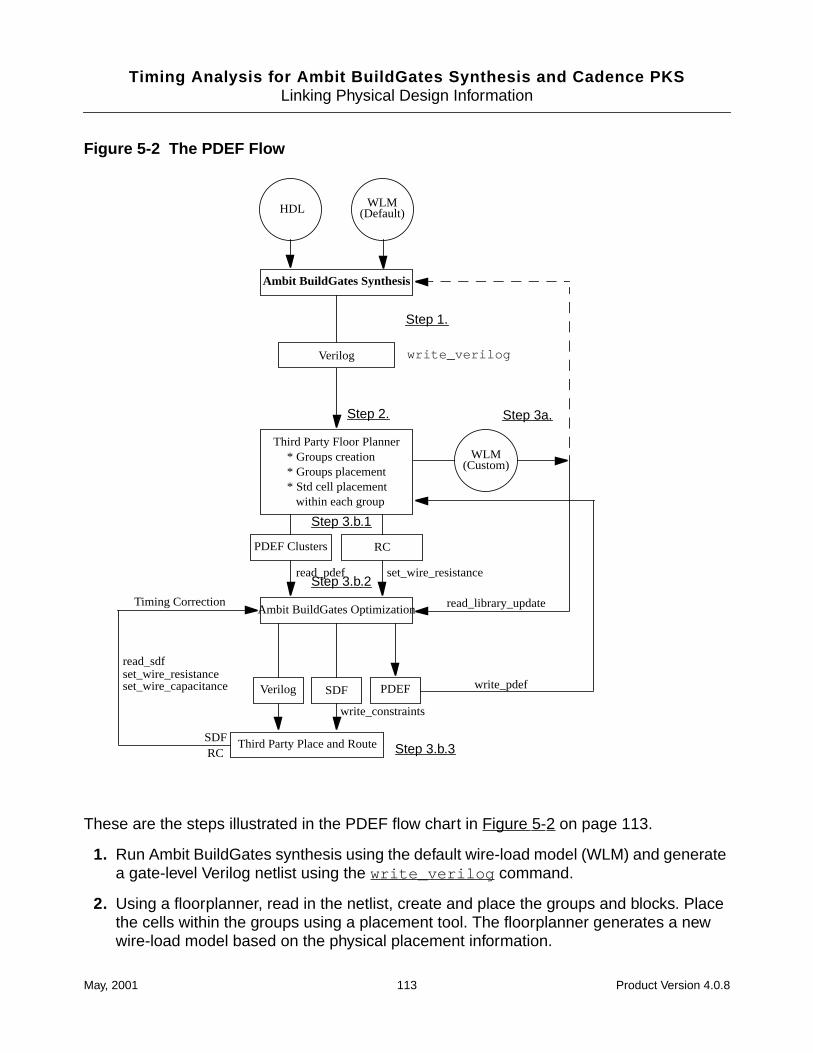
Timing Analysis for Ambit BuildGates Synthesis and Cadence PKSLinking Physical Design Information
Figure 5-2 The PDEF Flow
These are the steps illustrated in the PDEF flow chart in Figure 5-2 on page 113.
1. Run Ambit BuildGates synthesis using the default wire-load model (WLM) and generatea gate-level Verilog netlist using the write_verilog command.
2. Using a floorplanner, read in the netlist, create and place the groups and blocks. Placethe cells within the groups using a placement tool. The floorplanner generates a newwire-load model based on the physical placement information.
HDL WLM
read_pdef set_wire_resistance
read_library_updateAmbit BuildGates OptimizationTiming Correction
read_sdfset_wire_resistanceset_wire_capacitance PDEF
SDFRC
write_constraints
write_pdef
(Default)
Ambit BuildGates Synthesis
Third Party Floor PlannerWLM
(Custom)* Groups creation* Groups placement* Std cell placement
within each group
Third Party Place and Route
Verilog
RCPDEF Clusters
SDFVerilog
write_verilog
Step 1.
Step 2. Step 3a.
Step 3.b.1
Step 3.b.2
Step 3.b.3
May, 2001 113 Product Version 4.0.8
Timing Analysis for Ambit BuildGates Synthesis and Cadence PKSLinking Physical Design Information
3. At this point, you can do either a. or b.
a. Re-run Ambit BuildGates synthesis using the new wire-load model.
b. Generate PDEF and RC data in addition to the new wire-load model.
If you follow option b. , continue with these steps:
3.b.1. Read the PDEF, RC data, and the new wire-load model into Ambit BuildGatessynthesis.
3.b.2. Run the optimization step only, and output a new Verilog netlist.
3.b.3. Run place and route.
4. Use the read_library_update to import the wire-load model into Ambit BuildGatessynthesis synthesis.
read_library_update filename
■ Read the PDEF file into Ambit BuildGates synthesis with the read_pdef command
read_pdef filename
■ Import the RC data by sourcing the net parasitics file containing theset_wire_capacitance and set_wire_resistance commands.
source parasitics.tcl
May, 2001 114 Product Version 4.0.8
Timing Analysis for Ambit BuildGates Synthesis and Cadence PKS
6Deriving the Timing Context for a Module
This chapter provides a basic understanding of the timing context in a module, how timinginformation may be extracted from the module, how this information may be used within theAmbit® BuildGates® synthesis environment, and phase shifts for single and multiple clocks.This chapter assumes that you are familiar with the logic optimization process.
This chapter contains the following information:
■ Timing Context of a Module on page 116
■ Using Time-Budgeting to Derive a Module’s Timing Context on page 117
May, 2001 115 Product Version 4.0.8
Timing Analysis for Ambit BuildGates Synthesis and Cadence PKSDeriving the Timing Context for a Module
Timing Context of a Module
The timing context is the complete set of constraints used to drive the synthesis of the modulebeing optimized. Typically, a timing context includes both global constraints as well asexternal constraints applied to a module’s boundary (ports).
Time-driven logic optimization requires a timing context from which the delay calculation ofall timing paths is derived. The synthesis results obtained are directly related to the accuracyof the timing context used to guide the synthesis process.
A module’s timing context may consist of the following constraints:
■ Operating conditions
■ Wireload model or table lookup to be used for the module
■ Clock definition and binding
■ Clock propagation mode
■ Data arrival time on input ports
■ Data required time on output ports
■ False paths or multicycle additions
■ Wireload model applied per individual port
■ External fanout load per individual port
■ External sources or sinks per individual port
■ External port capacitance per individual port
■ Cell drive strength for any external driver per individual port
■ Slew rate requirements for signal transition per individual port
■ Design rule constraints such as fanout_limit
For more information about the list of constraints, see Chapter 4, “Setting Timing Constraints.”Typical approaches for the synthesis of a design module can be found in Chapter 2,“Choosing a Methodology.”.
May, 2001 116 Product Version 4.0.8
Timing Analysis for Ambit BuildGates Synthesis and Cadence PKSDeriving the Timing Context for a Module
Using Time-Budgeting to Derive a Module’s TimingContext
The recommended methodology uses a top-down compile strategy for building large designs,and using hierarchical synthesis for the lower-level design trees. Using this methodologytime-budgets must be developed for these lower-level design trees, and then the design treesmust be rebuilt in parallel. To build these lower level design trees in parallel you must firstproperly time-budget the timing constraint information. Ambit BuildGates synthesis offers thecapability to automatically derive optimal timing-budgets by using an integrated time-budgeting solution. Time-budgeting is not discussed in detail here.
The capability to do automatic derivation and extraction of the “actual” timing context for alower-level module instance is a must for achieving timing convergence with large designdatabases. You may already be familiar with the problem of trying to derive and properly usea module’s timing context. Ambit BuildGates synthesis offers several advantages in this areaabove and beyond the baseline capability offered by other synthesis tools. The AmbitBuildGates synthesis tool has the following advantages for timing extraction:
■ It has a very fast timing engine that allows for quick derivation of a module’s timingcontext.
■ It provides the capability of extracting a module’s timing context at any point in the designhierarchy for an integrated time-budgeting solution.
■ It extracts data correctly across multiple clock domains.
Ambit BuildGates synthesis is designed to support more than one timing context per module.It allows you to specify which timing context to use for a particular optimization. This is anextremely powerful architecture which forms the basis of many features. For example, it is thisarchitecture that lets you read a large design database into memory, execute time-budgetingon some number of lower-level module instances, and then lets you scope to those moduleinstances and extract the time-budgeted timing context from them instead of the timingcontext as derived from the circuit topology.
Using the dont_modify and do_uniquely_instantiate Commands
In a hierarchical design methodology, it is likely that a module is instantiated multiple timeswithin the design hierarchy. A common problem that this causes is whether or not to makeunique those design objects that are instantiated multiple times.
May, 2001 117 Product Version 4.0.8
Timing Analysis for Ambit BuildGates Synthesis and Cadence PKSDeriving the Timing Context for a Module
Making Design Objects Unique
The advantage of building the design object once and using dont_modify instead is thereduction in the compute overhead that results in building hierarchical design trees containingthese objects. The rule of thumb is that making an object unique should only be necessary ifone instance of the design object resides in an environment which is significantly differentfrom other instances of the same design object. If the objects were not unique, the designwould be built to meet the “worst-case” timing specifications. The resulting area penalty to theoverall design if it is not made unique could be significant, depending upon the number ofinstances of the design object in the design.
Ambit BuildGates synthesis has the capability of making instances of a current moduleunique. This is done using the do_uniquely_instantiate command. This command letsyou either specify a list of instances to be made unique or you can make all instances of thecurrent module unique. If hierarchical synthesis from the RTL source is performed, thiscommand is automatically executed as part of the do_optimize command flow.
For more information, see do_uniquely_instantiate and do_optimize in theCommand Reference for Ambit BuildGates Synthesis and Cadence PKS
Using dont_modify
Another problem exists when using a hierarchical synthesis methodology. If a design ispartitioned into approximately 50K gate hierarchical objects and a module is instantiated inmore than one of these objects, then the module name could overlap in memory when thecomplete design is read into memory. This can be prevented by associating thedont_modify property with it during the synthesis of the hierarchical objects. If you want tohave different timing contexts for each instance of the module, then you must make thoseinstances unique from within the scope of the full design to ensure a unique namingconvention on those instances.
Deriving the Timing Context in Synthesis
Deriving the timing context within Ambit BuildGates synthesis is a relatively straightforwardprocess. Three commands are used to execute this procedure and two primary variables aremanipulated during the process.
The commands used are listed below:
■ do_derive_context
Extracts the timing context of a particular instance.
■ write_assertions
May, 2001 118 Product Version 4.0.8
Timing Analysis for Ambit BuildGates Synthesis and Cadence PKSDeriving the Timing Context for a Module
Dumps the timing context out of memory and into a file.
■ do_time_budget
Executes the integrated time-budgeting algorithm on the sub design’s timing contextinformation.
See the Command Reference for Ambit BuildGates Synthesis and Cadence PKS forfurther information on the syntax for do_derive_context , write_assertions , anddo_time_budget .
Setting the Timing Context for Synthesis
In the ac_shell environment, two primary variables are used to control the timing contextused for logic optimization and to control the specific module being optimized.
The variables used are:
■ top_timing_module
Selects the module to be used by subsequent commands as a context for setting timingconstraints.
■ current_module
Controls the scope of the module on which an action is taking place (compilation,extraction, and so on)
See set_top_timing_module and set_current_module in the CommandReference for Ambit BuildGates Synthesis and Cadence PKS.
In most cases, the top_timing_module variable is set to point to the root of the designtree and the current_module variable is used to control the design being optimized. Thefollowing examples show how to set the values of these variables under different compilationscenarios. In these examples setup_libraries and apply_constraints are user-specified Tcl procedures and not ac_shell commands.
Example: Case 1 Single Module
If a single module is compiled independently of any other modules, then both thetop_timing_module variable and the current_module variable should be set topoint to this module. This is shown in the example below:
setup_libraries
read_verilog foo.v
do_build_generic
May, 2001 119 Product Version 4.0.8
Timing Analysis for Ambit BuildGates Synthesis and Cadence PKSDeriving the Timing Context for a Module
set_top_timing_module foo
set_current_module foo
apply_constraints
do_optimize
...
Example: Case 2 Hierarchical Synthesis
If hierarchical synthesis is being performed, multiple modules will exist in memory. In thiscase, you would typically apply timing constraints only to the root of the design tree. Timingconstraints for all other modules are automatically derived during the optimization. Thetop_timing_module should point to the root of the design tree before applying the timingconstraints. The value of the current_module should also point to the root of the designtree as this is the starting point for the optimization. These values do not need to be changedduring the optimization.
setup_libraries
read_verilog bot.v top.v mid.v
do_build_generic
set_top_timing_module top
set_current_module top
apply_constraints
do_optimize
...
Example: Case 3 Time-Budgeted Modules
Take the case of using a structural database from which the time-budgeted constraintinformation for lower-level modules is extracted to rebuild the design in parallel. As in theexample above, top_timing_module and current_module should both point to theroot of the design tree before applying the timing constraints. The values of these variablesremain unchanged when performing time budgeting and when extracting the timing contexton lower-level module instances.The value of the current_module variable changes onlywhen writing out the timing context for a lower-level module.
setup_libraries
read_verilog top_str.v
do_build_generic
set_top_timing_module top
set_current_module top
apply_constraints
do_derive_context {i_2 i_3/i_1}
set_current_module foo
May, 2001 120 Product Version 4.0.8
Timing Analysis for Ambit BuildGates Synthesis and Cadence PKSDeriving the Timing Context for a Module
write_assertions foo.cntxt
set_current_module top
set_current_module foobar
write_assertions foobar.cntxt
...
Here i_2 is a top-level instance of module foo and i_3/i_1 is an instance of modulefoobar .
Note: The value of the top_timing_module variable must be set to the root of the designtree. This variable need only change if you want to recompile a lower-level module in memoryand simultaneously use the time-budgeted timing context for that module in the recompilation.
In this case, the top_timing_module variable switches the timing context used from thatof the circuit topology (top-level timing context) to that of the time-budgeted timing context.
setup_libraries
read_verilog top_str.v
do_build_generic
set_top_timing_module top
set_current_module top
apply_constraints
do_time_budget
set_current_module foobar
set_top_timing_module foobar
do_optimize
...
An example Tcl procedure to derive context is given below:
# This script is used to derive context on a module.
# It derives the context on first instance of the module found by find -instances.
# You can easily modify this to pass in a specific instance name.
#
# two arguments:module name to derive_context on
# and file name for write_assertions output.
#
# sample call: go_do_derive_module foo ./assertion_files/foo.cntxt
#
proc go_do_derive_module { what outFile } {
puts "searching for first instances of $what :"
set list ""
set allinstances [find -instances *]
foreach i $allinstances {
May, 2001 121 Product Version 4.0.8
Timing Analysis for Ambit BuildGates Synthesis and Cadence PKSDeriving the Timing Context for a Module
set testname [get_info [get_info $i cellref] name]
if { $testname == "$what" } {
puts "found instance $i of $what"
do_derive_context $i
set save_top_mod [get_current_module]
set_current_module $what
write_assertions $outFile
set_current_module $save_top_mod
break
}
}
puts "write_assertions completed for $what ."
}
Using do_derive_context with Backannotated Timing and RC Information
Ambit BuildGates synthesis supports the ability to backannotate SDF timing information aswell as distributed RC interconnect information. This information is used when deriving amodule’s timing context for hierarchical resynthesis. The following example shows how AmbitBuildGates synthesis uses the backannotated data, based on the assumption that you havebackannotated both SDF timing information as well as lumped capacitive information (lumpedC on a per net basis). A sample circuit is shown below to describe the operation ofdo_derive_context .
Assume that modules mid_drv and mid_rcv represent two hierarchical modules of ~50Kgates each. These are also the boundaries for which you want to derive timing context for usein hierarchical resynthesis of these modules.
Figure 6-1 on page 123 contains two lower-level modules, bot_drv and bot_rcv .top_drv_rcv is the top-level interconnect between the modules. It is connected to portsdrv_out of instance m0 and rcv_in of instance m1. The buf8x macrocell in modulebot_drv , instance u1, is the source driver on the top-level net, top_drv_rcv . This celldrives a total fanout of five, four of which are in module bot_rcv and one of which iscontained in the same module as the source driver.
We will now examine what happens as do_derive_context is executed on instance m0ofmid_drv and instance m1 of mid_rcv .
May, 2001 122 Product Version 4.0.8
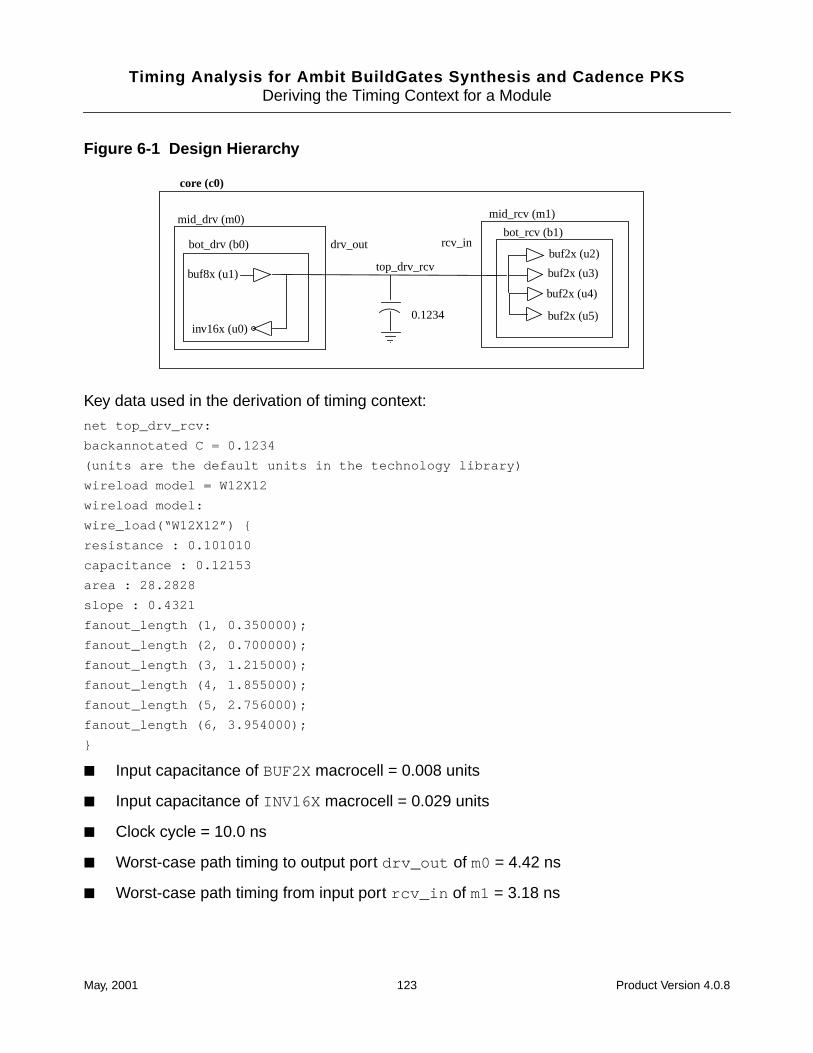
Timing Analysis for Ambit BuildGates Synthesis and Cadence PKSDeriving the Timing Context for a Module
Figure 6-1 Design Hierarchy
Key data used in the derivation of timing context:
net top_drv_rcv:
backannotated C = 0.1234
(units are the default units in the technology library)
wireload model = W12X12
wireload model:
wire_load(“W12X12”) {
resistance : 0.101010
capacitance : 0.12153
area : 28.2828
slope : 0.4321
fanout_length (1, 0.350000);
fanout_length (2, 0.700000);
fanout_length (3, 1.215000);
fanout_length (4, 1.855000);
fanout_length (5, 2.756000);
fanout_length (6, 3.954000);
}
■ Input capacitance of BUF2X macrocell = 0.008 units
■ Input capacitance of INV16X macrocell = 0.029 units
■ Clock cycle = 10.0 ns
■ Worst-case path timing to output port drv_out of m0= 4.42 ns
■ Worst-case path timing from input port rcv_in of m1 = 3.18 ns
buf2x (u2)
buf2x (u3)
buf2x (u4)
buf2x (u5)
bot_rcv (b1)
mid_rcv (m1)
inv16x (u0)
buf8x (u1)
bot_drv (b0)
mid_drv (m0)
0.1234
top_drv_rcv
rcv_indrv_out
core (c0)
May, 2001 123 Product Version 4.0.8
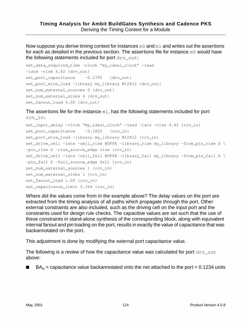
Timing Analysis for Ambit BuildGates Synthesis and Cadence PKSDeriving the Timing Context for a Module
Now suppose you derive timing context for instances m0and m1and writes out the assertionsfor each as detailed in the previous section. The assertions file for instance m0would havethe following statements included for port drv_out :
set_data_required_time -clock “my_ideal_clock” -lead
-late -rise 6.82 {drv_out}
set_port_capacitance -0.1795 {drv_out}
set_port_wire_load -library my_library W12X12 {drv_out}
set_num_external_sources 0 {drv_out}
set_num_external_sinks 4 {drv_out}
set_fanout_load 4.00 {drv_out}
The assertions file for the instance m1, has the following statements included for portrcv_in :
set_input_delay -clock “my_ideal_clock” -lead -late -rise 4.42 {rcv_in}
set_port_capacitance -0.1825 {rcv_in}
set_port_wire_load -library my_library W12X12 {rcv_in}
set_drive_cell -late -cell_rise BUF8X -library_rise my_library -from_pin_rise A \
-pin_rise Z -rise_source_edge rise {rcv_in}
set_drive_cell -late -cell_fall BUF8X -library_fall my_library -from_pin_fall A \
-pin_fall Z -fall_source_edge fall {rcv_in}
set_num_external_sources 1 {rcv_in}
set_num_external_sinks 1 {rcv_in}
set_fanout_load 1.00 {rcv_in}
set_capacitance_limit 0.344 {rcv_in}
Where did the values come from in the example above? The delay values on the port areextracted from the timing analysis of all paths which propagate through the port. Otherexternal constraints are also included, such as the driving cell on the input port and theconstraints used for design rule checks. The capacitive values are set such that the use ofthese constraints in stand-alone synthesis of the corresponding block, along with equivalentinternal fanout and pin loading on the port, results in exactly the value of capacitance that wasbackannotated on the port.
This adjustment is done by modifying the external port capacitance value.
The following is a review of how the capacitance value was calculated for port drv_outabove:
■ BAn = capacitance value backannotated onto the net attached to the port = 0.1234 units
May, 2001 124 Product Version 4.0.8
Timing Analysis for Ambit BuildGates Synthesis and Cadence PKSDeriving the Timing Context for a Module
■ ∑pincapext = sum of all external pin capacitances on the port
= 4 BUF2X input pins * 0.008 units/BUF2X input
= 0.032 units
■ WLc = capacitance extracted from the wireload model with a fanout of 5
= 2.756 * 0.12153
= 0.3349 units
The equation for the modified value of the external port capacitance is:
modified_port_cap = BAn + ∑pincapext - WLc
= 0.1234 + 0.032 - 0.3349
= -0.1795
The value for the modified port capacitance on port rcv_in of instance m1is calculated in asimilar fashion. The only change being the value of the external pin capacitance, whichbecomes 0.029 due to the INV16X macrocell.
May, 2001 125 Product Version 4.0.8

Timing Analysis for Ambit BuildGates Synthesis and Cadence PKSDeriving the Timing Context for a Module
May, 2001 126 Product Version 4.0.8
Timing Analysis for Ambit BuildGates Synthesis and Cadence PKS
7Generating and Understanding TimingReports
This chapter contains the following information:
■ Types of Reports for Timing on page 128
■ Checking the Design for Timing Problems on page 128
■ Generating Library Reports on page 129
■ Generating Timing Reports on page 129
■ Generating Design Information Reports on page 130
❑ Generating Clock Reports on page 130
❑ Generating Port Reports on page 132
❑ Generating Cell Reports on page 133
❑ Generating Net and Pin Reports on page 134
■ Generating Path Exception Reports on page 136
■ Understanding Reports on page 137
❑ Phase Shift in Single Clock Domains on page 137
❑ Phase Shift in Multiple Clock Domains on page 137
❑ Loop Check and Time Borrowed on page 139
May, 2001 127 Product Version 4.0.8
Timing Analysis for Ambit BuildGates Synthesis and Cadence PKSGenerating and Understanding Timing Reports
Types of Reports for Timing
The various reports available for timing contain information to help you answer importantquestions about your design such as:
■ How do I know if my design has problems
■ How do I know if my design passes (or fails) timing analysis
■ Where are the violations
■ What were the constraints and exceptions for this analysis
■ How were the delays calculated
Checking the Design for Timing Problems
Your design must meet certain requirements before timing analysis can run with accuracy. Forexample, you must have an ideal clock defined before you can run the analysis. Otherproblems can potentially affect analysis results.
The check_timing command generates messages about the potential problems in thedesign. The messages are categorized as follows with the most serious problem first:
■ ERROR
Timing analysis cannot be run for the reason stated in the message.
■ WARNING
Analysis results may be erroneous due to the stated condition. You should be aware ofthe consequences if you choose to ignore a warning.
■ INFO
Informative messages about your design. You should look through these messages tosee that the libraries are as expected.
Before you run the analysis you can check your design after loading the libraries and settingconstraints.
➤ To identify the timing problems in the design, use the check_timing command beforegenerating a timing report. The example below shows the command and the results fora design that is missing some assertions.
ac_shell>check_timing
--> WARNING: No drive assertion found at port ’I’ <TA-107>.
May, 2001 128 Product Version 4.0.8
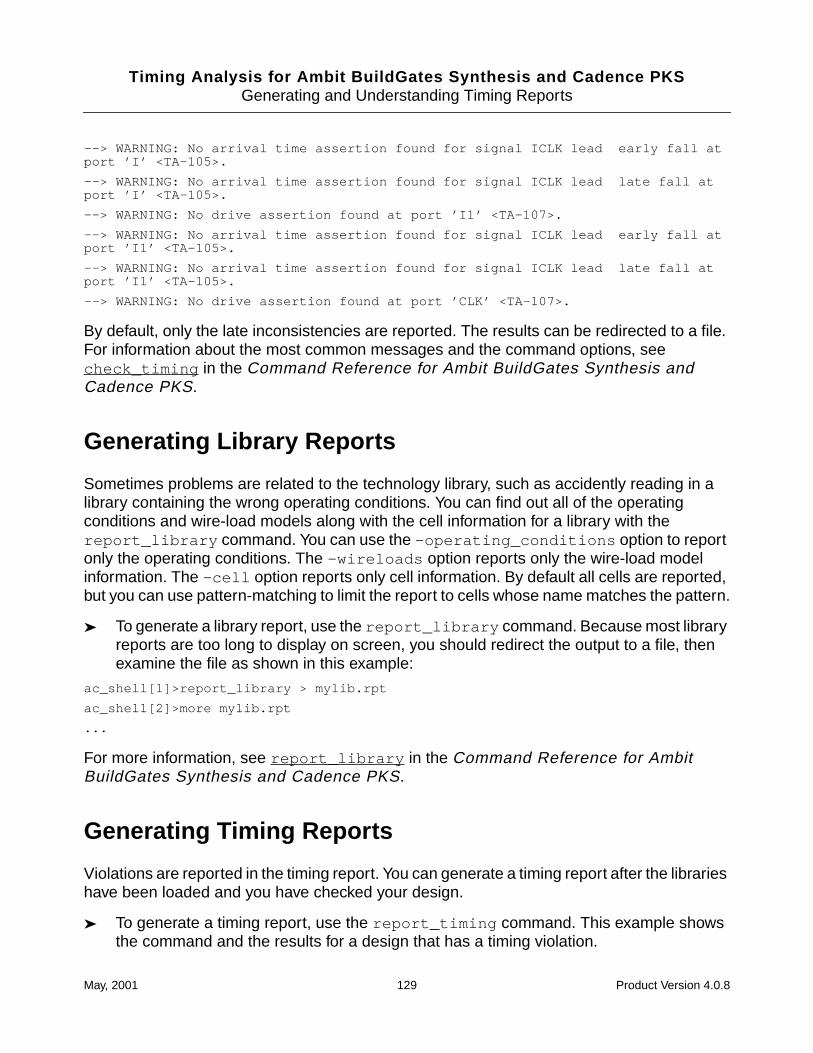
Timing Analysis for Ambit BuildGates Synthesis and Cadence PKSGenerating and Understanding Timing Reports
--> WARNING: No arrival time assertion found for signal ICLK lead early fall atport ’I’ <TA-105>.
--> WARNING: No arrival time assertion found for signal ICLK lead late fall atport ’I’ <TA-105>.
--> WARNING: No drive assertion found at port ’I1’ <TA-107>.
--> WARNING: No arrival time assertion found for signal ICLK lead early fall atport ’I1’ <TA-105>.
--> WARNING: No arrival time assertion found for signal ICLK lead late fall atport ’I1’ <TA-105>.
--> WARNING: No drive assertion found at port ’CLK’ <TA-107>.
By default, only the late inconsistencies are reported. The results can be redirected to a file.For information about the most common messages and the command options, seecheck_timing in the Command Reference for Ambit BuildGates Synthesis andCadence PKS.
Generating Library Reports
Sometimes problems are related to the technology library, such as accidently reading in alibrary containing the wrong operating conditions. You can find out all of the operatingconditions and wire-load models along with the cell information for a library with thereport_library command. You can use the -operating_conditions option to reportonly the operating conditions. The -wireloads option reports only the wire-load modelinformation. The -cell option reports only cell information. By default all cells are reported,but you can use pattern-matching to limit the report to cells whose name matches the pattern.
➤ To generate a library report, use the report_library command. Because most libraryreports are too long to display on screen, you should redirect the output to a file, thenexamine the file as shown in this example:
ac_shell[1]>report_library > mylib.rpt
ac_shell[2]>more mylib.rpt
...
For more information, see report_library in the Command Reference for AmbitBuildGates Synthesis and Cadence PKS.
Generating Timing Reports
Violations are reported in the timing report. You can generate a timing report after the librarieshave been loaded and you have checked your design.
➤ To generate a timing report, use the report_timing command. This example showsthe command and the results for a design that has a timing violation.
May, 2001 129 Product Version 4.0.8
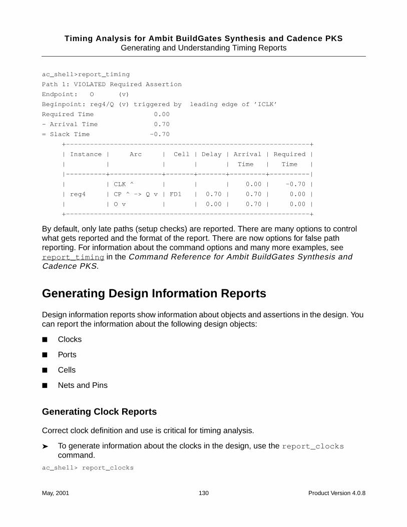
Timing Analysis for Ambit BuildGates Synthesis and Cadence PKSGenerating and Understanding Timing Reports
ac_shell>report_timing
Path 1: VIOLATED Required Assertion
Endpoint: O (v)
Beginpoint: reg4/Q (v) triggered by leading edge of ’ICLK’
Required Time 0.00
- Arrival Time 0.70
= Slack Time -0.70
+-------------------------------------------------------------+
| Instance | Arc | Cell | Delay | Arrival | Required |
| | | | | Time | Time |
|----------+-------------+-------+-------+---------+----------|
| | CLK ^ | | | 0.00 | -0.70 |
| reg4 | CP ^ -> Q v | FD1 | 0.70 | 0.70 | 0.00 |
| | O v | | 0.00 | 0.70 | 0.00 |
+-------------------------------------------------------------+
By default, only late paths (setup checks) are reported. There are many options to controlwhat gets reported and the format of the report. There are now options for false pathreporting. For information about the command options and many more examples, seereport_timing in the Command Reference for Ambit BuildGates Synthesis andCadence PKS.
Generating Design Information Reports
Design information reports show information about objects and assertions in the design. Youcan report the information about the following design objects:
■ Clocks
■ Ports
■ Cells
■ Nets and Pins
Generating Clock Reports
Correct clock definition and use is critical for timing analysis.
➤ To generate information about the clocks in the design, use the report_clockscommand.
ac_shell> report_clocks
May, 2001 130 Product Version 4.0.8
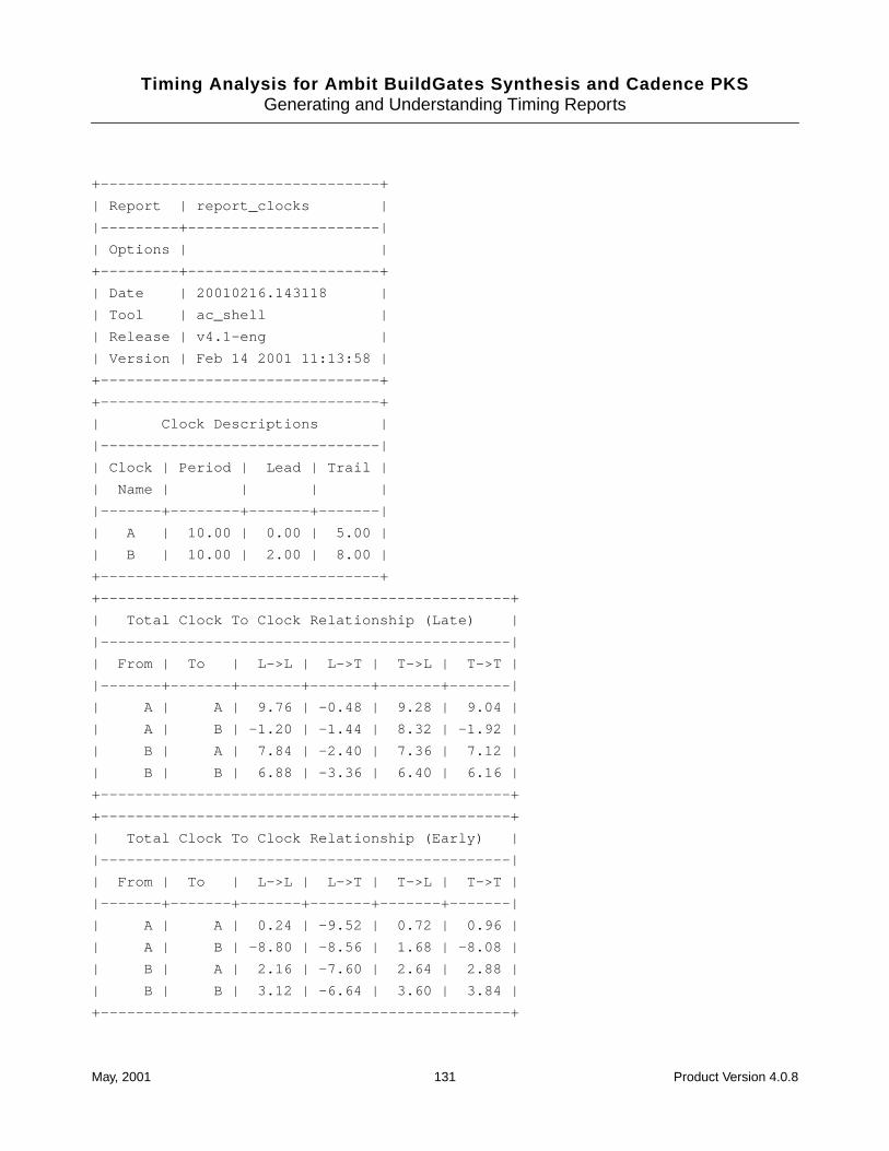
Timing Analysis for Ambit BuildGates Synthesis and Cadence PKSGenerating and Understanding Timing Reports
+--------------------------------+
| Report | report_clocks |
|---------+----------------------|
| Options | |
+---------+----------------------+
| Date | 20010216.143118 |
| Tool | ac_shell |
| Release | v4.1-eng |
| Version | Feb 14 2001 11:13:58 |
+--------------------------------+
+--------------------------------+
| Clock Descriptions |
|--------------------------------|
| Clock | Period | Lead | Trail |
| Name | | | |
|-------+--------+-------+-------|
| A | 10.00 | 0.00 | 5.00 |
| B | 10.00 | 2.00 | 8.00 |
+--------------------------------+
+-----------------------------------------------+
| Total Clock To Clock Relationship (Late) |
|-----------------------------------------------|
| From | To | L->L | L->T | T->L | T->T |
|-------+-------+-------+-------+-------+-------|
| A | A | 9.76 | -0.48 | 9.28 | 9.04 |
| A | B | -1.20 | -1.44 | 8.32 | -1.92 |
| B | A | 7.84 | -2.40 | 7.36 | 7.12 |
| B | B | 6.88 | -3.36 | 6.40 | 6.16 |
+-----------------------------------------------+
+-----------------------------------------------+
| Total Clock To Clock Relationship (Early) |
|-----------------------------------------------|
| From | To | L->L | L->T | T->L | T->T |
|-------+-------+-------+-------+-------+-------|
| A | A | 0.24 | -9.52 | 0.72 | 0.96 |
| A | B | -8.80 | -8.56 | 1.68 | -8.08 |
| B | A | 2.16 | -7.60 | 2.64 | 2.88 |
| B | B | 3.12 | -6.64 | 3.60 | 3.84 |
+-----------------------------------------------+
May, 2001 131 Product Version 4.0.8
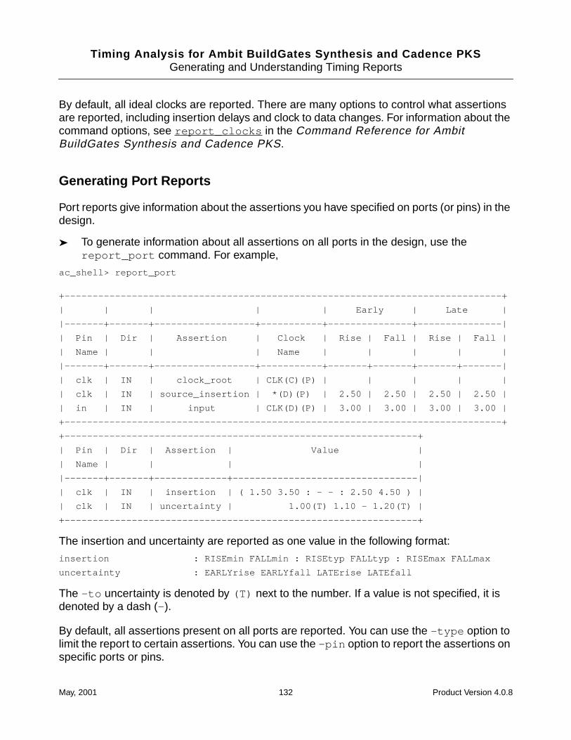
Timing Analysis for Ambit BuildGates Synthesis and Cadence PKSGenerating and Understanding Timing Reports
By default, all ideal clocks are reported. There are many options to control what assertionsare reported, including insertion delays and clock to data changes. For information about thecommand options, see report_clocks in the Command Reference for AmbitBuildGates Synthesis and Cadence PKS.
Generating Port Reports
Port reports give information about the assertions you have specified on ports (or pins) in thedesign.
➤ To generate information about all assertions on all ports in the design, use thereport_port command. For example,
ac_shell> report_port
+------------------------------------------------------------------------------+
| | | | | Early | Late |
|-------+-------+------------------+-----------+---------------+---------------|
| Pin | Dir | Assertion | Clock | Rise | Fall | Rise | Fall |
| Name | | | Name | | | | |
|-------+-------+------------------+-----------+-------+-------+-------+-------|
| clk | IN | clock_root | CLK(C)(P) | | | | |
| clk | IN | source_insertion | *(D)(P) | 2.50 | 2.50 | 2.50 | 2.50 |
| in | IN | input | CLK(D)(P) | 3.00 | 3.00 | 3.00 | 3.00 |
+------------------------------------------------------------------------------+
+---------------------------------------------------------------+
| Pin | Dir | Assertion | Value |
| Name | | | |
|-------+-------+-------------+---------------------------------|
| clk | IN | insertion | ( 1.50 3.50 : - - : 2.50 4.50 ) |
| clk | IN | uncertainty | 1.00(T) 1.10 - 1.20(T) |
+---------------------------------------------------------------+
The insertion and uncertainty are reported as one value in the following format:
insertion : RISEmin FALLmin : RISEtyp FALLtyp : RISEmax FALLmax
uncertainty : EARLYrise EARLYfall LATErise LATEfall
The -to uncertainty is denoted by (T) next to the number. If a value is not specified, it isdenoted by a dash (- ).
By default, all assertions present on all ports are reported. You can use the -type option tolimit the report to certain assertions. You can use the -pin option to report the assertions onspecific ports or pins.
May, 2001 132 Product Version 4.0.8
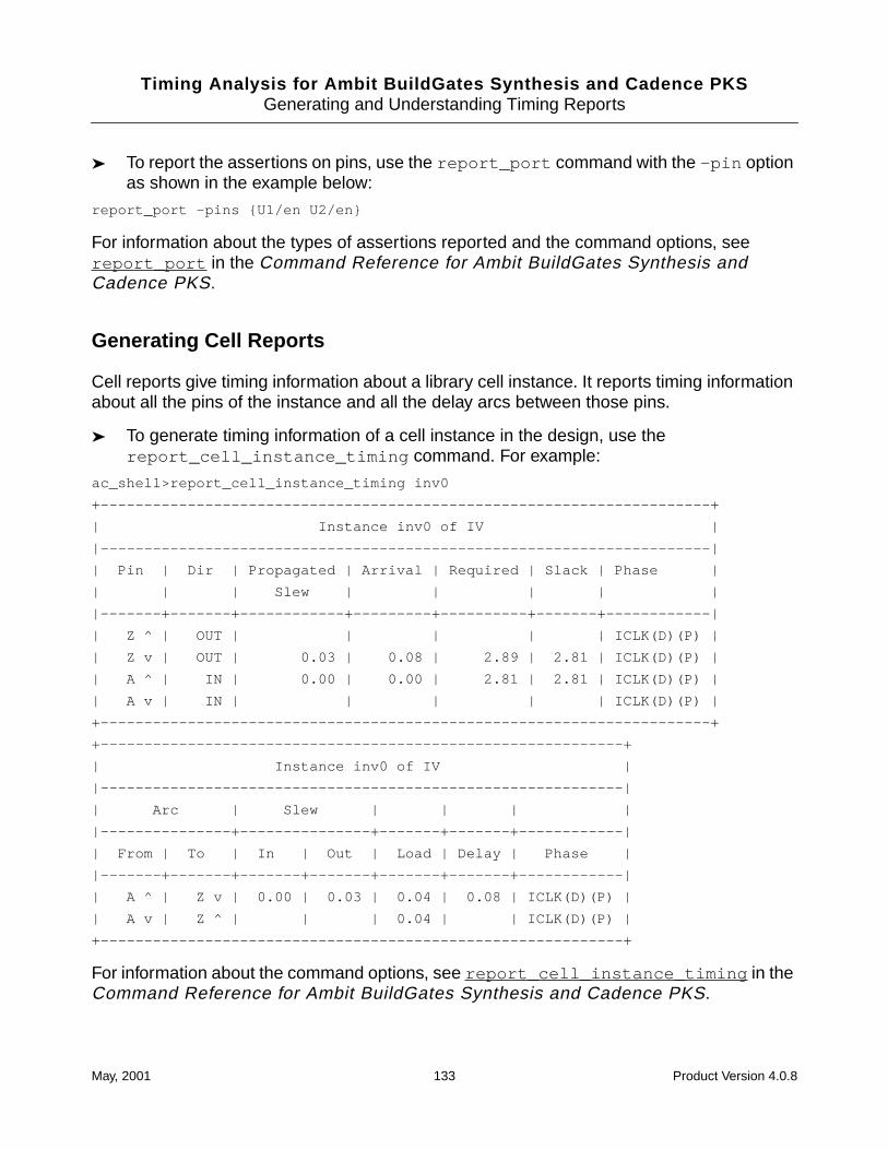
Timing Analysis for Ambit BuildGates Synthesis and Cadence PKSGenerating and Understanding Timing Reports
➤ To report the assertions on pins, use the report_port command with the -pin optionas shown in the example below:
report_port -pins {U1/en U2/en}
For information about the types of assertions reported and the command options, seereport_port in the Command Reference for Ambit BuildGates Synthesis andCadence PKS.
Generating Cell Reports
Cell reports give timing information about a library cell instance. It reports timing informationabout all the pins of the instance and all the delay arcs between those pins.
➤ To generate timing information of a cell instance in the design, use thereport_cell_instance_timing command. For example:
ac_shell>report_cell_instance_timing inv0
+----------------------------------------------------------------------+
| Instance inv0 of IV |
|----------------------------------------------------------------------|
| Pin | Dir | Propagated | Arrival | Required | Slack | Phase |
| | | Slew | | | | |
|-------+-------+------------+---------+----------+-------+------------|
| Z ^ | OUT | | | | | ICLK(D)(P) |
| Z v | OUT | 0.03 | 0.08 | 2.89 | 2.81 | ICLK(D)(P) |
| A ^ | IN | 0.00 | 0.00 | 2.81 | 2.81 | ICLK(D)(P) |
| A v | IN | | | | | ICLK(D)(P) |
+----------------------------------------------------------------------+
+------------------------------------------------------------+
| Instance inv0 of IV |
|------------------------------------------------------------|
| Arc | Slew | | | |
|---------------+---------------+-------+-------+------------|
| From | To | In | Out | Load | Delay | Phase |
|-------+-------+-------+-------+-------+-------+------------|
| A ^ | Z v | 0.00 | 0.03 | 0.04 | 0.08 | ICLK(D)(P) |
| A v | Z ^ | | | 0.04 | | ICLK(D)(P) |
+------------------------------------------------------------+
For information about the command options, see report_cell_instance_timing in theCommand Reference for Ambit BuildGates Synthesis and Cadence PKS.
May, 2001 133 Product Version 4.0.8
Timing Analysis for Ambit BuildGates Synthesis and Cadence PKSGenerating and Understanding Timing Reports
Generating Net and Pin Reports
Net and pin reports are used extensively in delay correlation where you need to comparedelays from different timing analyzers and understand how the delays were calculated.
➤ To generate a net or pin report, use the report_net command as shown in thisexample:
report_net -net clkA
By default, the report_net command now provides additional information about theinterconnect delay model. You can get the older 3.0 format by using the -old option. Otheroptions let you find nets that have not been backannotated or that exceed a specified numberof fanouts. See report_net in the Command Reference for Ambit BuildGatesSynthesis and Cadence PKS for a complete command description.
For each net source pin, the following is reported:
■ pin name
■ pin direction
■ cell name
■ capacitance
■ slew per phase
■ Reduced Net Model
This is the trans-admittance model that is used to model the net from this source to eachof its sinks. Elmore Delay is the only trans-admittance model used now, a higher-ordermodel will be available in a future release. The trans-admittance model is used tocalculate the interconnect delay.
■ Driver Load Model
This is the source-admittance model which currently is either PI or CTOTAL. This modelis used to calculate the gate delay.
■ Driver Load Parameters
These are the parameters used in the driver load model. For CTOTAL, this is the lumpedcapacitance (C). For PI , this is Cnear , Rpi , and Cfar .
For each of the sinks for the source, the following is reported.
■ pin name
■ direction
May, 2001 134 Product Version 4.0.8

Timing Analysis for Ambit BuildGates Synthesis and Cadence PKSGenerating and Understanding Timing Reports
■ cell
■ cap
■ delay and slew per phase
■ Reduced Net Parameters
These are the parameters used in the reduced net model. This currently is the Elmoretime constant for the source->sink. (Refer to the Reduced Net Model in the source. Thereduced net model is the same for all sinks on a source, but the reduced net parameterswill be different.)
The general information section contains the following entries:
■ Net Name
■ Number of Sources
■ Number of sinks
■ Number of bidis
■ Wireload Model
This is one of the following:
❑ Detailed Spef/Spf
❑ Reduced Spef/Spf
❑ DCLwireload_model_name library_name
❑ .lib wireload_model_name library_name
❑ Steiner Tree
❑ Pks Half Perimeter
❑ Pks Global Route
■ Wire Capacitance
Total capacitance due to interconnect. Does not include pin loads.
■ Wire Resistance
Total resistance due to interconnect.
■ Total Capacitance
Total capacitance including pin loads.
May, 2001 135 Product Version 4.0.8
Timing Analysis for Ambit BuildGates Synthesis and Cadence PKSGenerating and Understanding Timing Reports
Generating Path Exception Reports
The report_path_exceptions command gives you a report of each path exception in atable.
➤ To generate a report of path exceptions, type this command in ac_shell
report_path_exceptions
Each path exception is listed per line, and each line corresponds to an assertion that you havemade. Any wildcards are expanded, and all pins are listed. Clocks are enclosed in quotes.Each column labeled From | Through | To corresponds to the -from , -through , -toused to assert the exception.
The final two columns are for Early | Late analysis mode. These columns contain thefollowing information:
■ <blank>
There is no assertion for this analysis mode.
■ delay n
The assertion set_path_delay_constraint n was made for this mode.
■ add n
The assertion set_cycle_addition n was made for this mode.
■ false
The assertion set_false_path was made for this mode.
■ ignored
This means that the assertion is ignored because another path exception has priority. Forassertions that have multiple pins, this means that all combinations have been ignored.The priorities are listed in Table 9-1 on page 188.
For more information and an example, see report_path_exceptions in the CommandReference for Ambit BuildGates Synthesis and Cadence PKS.
May, 2001 136 Product Version 4.0.8
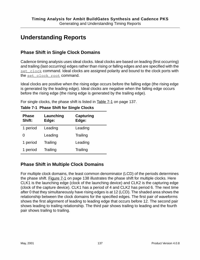
Timing Analysis for Ambit BuildGates Synthesis and Cadence PKSGenerating and Understanding Timing Reports
Understanding Reports
Phase Shift in Single Clock Domains
Cadence timing analysis uses ideal clocks. Ideal clocks are based on leading (first occurring)and trailing (last occurring) edges rather than rising or falling edges and are specified with theset_clock command. Ideal clocks are assigned polarity and bound to the clock ports withthe set_clock_root command.
Ideal clocks are positive when the rising edge occurs before the falling edge (the rising edgeis generated by the leading edge). Ideal clocks are negative when the falling edge occursbefore the rising edge (the rising edge is generated by the trailing edge).
For single clocks, the phase shift is listed in Table 7-1 on page 137.
Phase Shift in Multiple Clock Domains
For multiple clock domains, the least common denominator (LCD) of the periods determinesthe phase shift. Figure 7-1 on page 138 illustrates the phase shift for multiple clocks. HereCLK1 is the launching edge (clock of the launching device) and CLK2 is the capturing edge(clock of the capture device). CLK1 has a period of 4 and CLK2 has period 6. The next timeafter 0 that they simultaneously have rising edges is at 12 (LCD). The shaded area shows therelationship between the clock domains for the specified edges. The first pair of waveformsshows the first alignment of leading to leading edge that occurs before 12. The second pairshows leading to trailing relationship. The third pair shows trailing to leading and the fourthpair shows trailing to trailing.
Table 7-1 Phase Shift for Single Clocks
PhaseShift:
LaunchingEdge:
CapturingEdge:
1 period Leading Leading
0 Leading Trailing
1 period Trailing Leading
1 period Trailing Trailing
May, 2001 137 Product Version 4.0.8
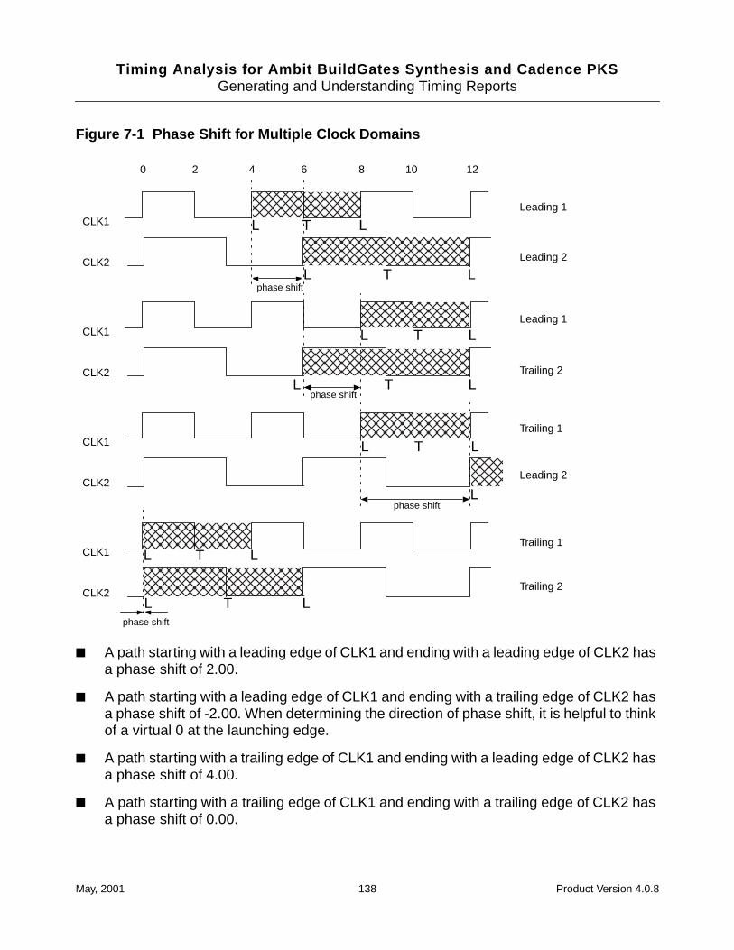
Timing Analysis for Ambit BuildGates Synthesis and Cadence PKSGenerating and Understanding Timing Reports
Figure 7-1 Phase Shift for Multiple Clock Domains
■ A path starting with a leading edge of CLK1 and ending with a leading edge of CLK2 hasa phase shift of 2.00.
■ A path starting with a leading edge of CLK1 and ending with a trailing edge of CLK2 hasa phase shift of -2.00. When determining the direction of phase shift, it is helpful to thinkof a virtual 0 at the launching edge.
■ A path starting with a trailing edge of CLK1 and ending with a leading edge of CLK2 hasa phase shift of 4.00.
■ A path starting with a trailing edge of CLK1 and ending with a trailing edge of CLK2 hasa phase shift of 0.00.
0 2 4 6 8 10 12
CLK1
CLK2
CLK1
CLK2
CLK1
CLK2
CLK1
CLK2
Leading 1
Leading 2
Leading 1
Leading 2
Trailing 1
Trailing 1
Trailing 2
Trailing 2
L
T
L LT
L LT
L LT
L LT
L LT
L
L L
L Tphase shift
phase shift
phase shift
phase shift
May, 2001 138 Product Version 4.0.8

Timing Analysis for Ambit BuildGates Synthesis and Cadence PKSGenerating and Understanding Timing Reports
Loop Check and Time Borrowed
For information about the loop check delay and time borrowing in latch-based designs, seeUnderstanding the Timing Report on page 206 in the Analyzing Latch-based Designssection.
May, 2001 139 Product Version 4.0.8

Timing Analysis for Ambit BuildGates Synthesis and Cadence PKSGenerating and Understanding Timing Reports
May, 2001 140 Product Version 4.0.8
Timing Analysis for Ambit BuildGates Synthesis and Cadence PKS
8Identifying and Eliminating False Paths
This chapter contains:
■ Critical False Path Verification Overview on page 142
■ Static and Robust False Paths on page 142
■ Reporting and Eliminating False Paths on page 149
■ Example: Timing Reports with False Path Analysis on page 152
May, 2001 141 Product Version 4.0.8
Timing Analysis for Ambit BuildGates Synthesis and Cadence PKSIdentifying and Eliminating False Paths
Critical False Path Verification Overview
By default, static timing analysis (STA), as performed by the report_timing command,uses vectorless analysis techniques to determine critical paths in a design. A critical path isthe path with the longest delay taken by a signal in a circuit. The delay of a critical pathdetermines the clock speed at which the circuit can be correctly operated. If the delay of thecritical path is more than the requirement, timing optimizations are performed on a section ofthe circuit to reduce the delay. Inaccuracies in identifying the critical path might lead toinaccurate estimation of the delay of the circuit and even cause timing optimizations to beapplied when not needed.
Cadence® timing analysis uses a fast search algorithm to identify critical paths in the netlist.STA only considers delays on the gates and does not consider functionality. Therefore, thedelay of the longest critical path is a pessimistic delay since the path could be a false path,meaning the path might never be excited by any input vector.
Critical false path verification (CFPV) analysis, however, does consider the functionality of thelibrary gates on a path and combines the functionality and timing delays to determine whethera path is a true path or a false path. A critical path obtained using the false path analysis is abetter representative of the delay of the netlist since the false paths are filtered during a falsepath analysis and only the delays of the true paths are considered.
False path analysis uses a sensitization criterion to determine whether a path is true or false.The false path identification feature available in Cadence timing analysis provides an optionto use one of the two sensitization criteria, static or robust.
This chapter describes the different false path identification features available.
Static and Robust False Paths
Every path in the design is either a true path or a false path depending on the logic gates thatare on the path. That is, a signal can travel the path (true path) or the logic function preventsa signal from traveling the path (false path). Cadence timing analysis supports two sets ofcriteria for determining a true path, static and robust. Both criteria consider the side inputs asdefined below.
Side Inputs
For a gate on the path under consideration, the side inputs are those inputs to the gate whichdo not fall on the path.
May, 2001 142 Product Version 4.0.8
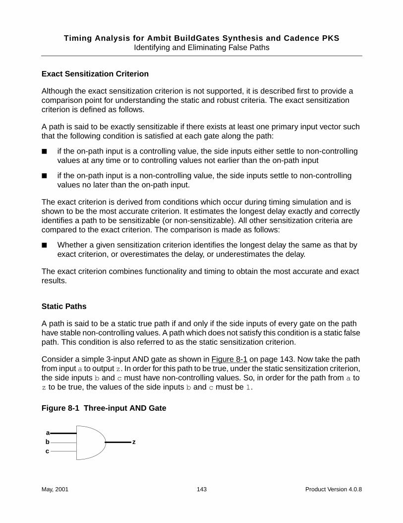
Timing Analysis for Ambit BuildGates Synthesis and Cadence PKSIdentifying and Eliminating False Paths
Exact Sensitization Criterion
Although the exact sensitization criterion is not supported, it is described first to provide acomparison point for understanding the static and robust criteria. The exact sensitizationcriterion is defined as follows.
A path is said to be exactly sensitizable if there exists at least one primary input vector suchthat the following condition is satisfied at each gate along the path:
■ if the on-path input is a controlling value, the side inputs either settle to non-controllingvalues at any time or to controlling values not earlier than the on-path input
■ if the on-path input is a non-controlling value, the side inputs settle to non-controllingvalues no later than the on-path input.
The exact criterion is derived from conditions which occur during timing simulation and isshown to be the most accurate criterion. It estimates the longest delay exactly and correctlyidentifies a path to be sensitizable (or non-sensitizable). All other sensitization criteria arecompared to the exact criterion. The comparison is made as follows:
■ Whether a given sensitization criterion identifies the longest delay the same as that byexact criterion, or overestimates the delay, or underestimates the delay.
The exact criterion combines functionality and timing to obtain the most accurate and exactresults.
Static Paths
A path is said to be a static true path if and only if the side inputs of every gate on the pathhave stable non-controlling values. A path which does not satisfy this condition is a static falsepath. This condition is also referred to as the static sensitization criterion.
Consider a simple 3-input AND gate as shown in Figure 8-1 on page 143. Now take the pathfrom input a to output z . In order for this path to be true, under the static sensitization criterion,the side inputs b and c must have non-controlling values. So, in order for the path from a toz to be true, the values of the side inputs b and c must be 1.
Figure 8-1 Three-input AND Gate
abc
z
May, 2001 143 Product Version 4.0.8
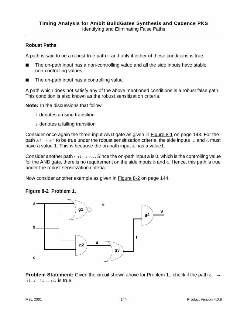
Timing Analysis for Ambit BuildGates Synthesis and Cadence PKSIdentifying and Eliminating False Paths
Robust Paths
A path is said to be a robust true path if and only if either of these conditions is true:
■ The on-path input has a non-controlling value and all the side inputs have stablenon-controlling values.
■ The on-path input has a controlling value.
A path which does not satisfy any of the above mentioned conditions is a robust false path.This condition is also known as the robust sensitization criteria.
Note: In the discussions that follow
↑ denotes a rising transition
↓ denotes a falling transition
Consider once again the three-input AND gate as given in Figure 8-1 on page 143. For thepath a↑ → z↑ to be true under the robust sensitization criteria, the side inputs b and c musthave a value 1. This is because the on-path input a has a value1.
Consider another path - a↓ → z↓. Since the on-path input a is 0, which is the controlling valuefor the AND gate, there is no requirement on the side inputs b and c . Hence, this path is trueunder the robust sensitization criteria.
Now consider another example as given in Figure 8-2 on page 144.
Figure 8-2 Problem 1.
Problem Statement: Given the circuit shown above for Problem 1., check if the path a↓ →d↓→ f ↓→ g↓ is true.
a
b
c
e
df
gg1
g2g3
g4
May, 2001 144 Product Version 4.0.8
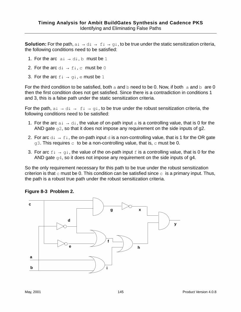
Timing Analysis for Ambit BuildGates Synthesis and Cadence PKSIdentifying and Eliminating False Paths
Solution: For the path, a↓ → d↓ → f ↓ → g↓, to be true under the static sensitization criteria,the following conditions need to be satisfied:
1. For the arc a ↓ → d↓, b must be 1
2. For the arc d↓ → f ↓, c must be 0
3. For the arc f ↓ → g↓, e must be 1
For the third condition to be satisfied, both a and b need to be 0. Now, if both a and b are 0then the first condition does not get satisfied. Since there is a contradiction in conditions 1and 3, this is a false path under the static sensitization criteria.
For the path, a↓ → d↓ → f ↓ → g↓, to be true under the robust sensitization criteria, thefollowing conditions need to be satisfied:
1. For the arc a↓ → d↓, the value of on-path input a is a controlling value, that is 0 for theAND gate g2 , so that it does not impose any requirement on the side inputs of g2.
2. For arc d↓ → f ↓, the on-path input d is a non-controlling value, that is 1 for the OR gateg3 . This requires c to be a non-controlling value, that is, c must be 0.
3. For arc f ↓ → g↓, the value of the on-path input f is a controlling value, that is 0 for theAND gate g4 , so it does not impose any requirement on the side inputs of g4.
So the only requirement necessary for this path to be true under the robust sensitizationcriterion is that c must be 0. This condition can be satisfied since c is a primary input. Thus,the path is a robust true path under the robust sensitization criteria.
Figure 8-3 Problem 2.
c
a
b
d
ef
i
h
g x
y
May, 2001 145 Product Version 4.0.8
Timing Analysis for Ambit BuildGates Synthesis and Cadence PKSIdentifying and Eliminating False Paths
Problem Statement : Given the design in Figure 8-3 on page 145, check if the followingpaths are true:
Path 1: c↑ → e↓→ f ↓→ h↓ → y↓
Path 2: b↑ → i ↑→ h↑ → y↑
Path 3: b↓ → d↑→ f ↑→ h↑ → y↑
Solution 1. For the path c↑ → e↓→ f ↓→ h↓ → y↓ to be true under the static sensitizationcriterion, the following conditions need to be satisfied:
■ For the arc c↑ → e↓ to be true there is no requirement since this transition will alwayspropagate through the NOT gate.
■ For the arc e↓→ f ↓ to be true, d must be 0; which in turn means b must be 1.
■ For the arc f ↓→ h↓, i must be 0, which in turn means that both a and b must be 0. Butthe requirement above says that b must be 1. Since there is a contradiction in the tworequirements, the path c↑ → e↓→ f ↓→ h↓ → y↓ is a false path under the staticsensitization criterion.
For the path c↑ → e↓→ f ↓→ h↓ → y↓ to be true under the robust sensitization criterion, thefollowing conditions need to be satisfied:
■ For the arc c↑ → e↓, there is no requirement since this transition will always propagate.
■ For the arch e↓→ f ↓, since e↓ is a non-controlling value, the side input d should alsobe a non-controlling value, that is d must be 0, which in turn means b must be 1.
■ For the arch f ↓→ h↓, since f ↓ is a non-controlling value, the side input i must be 0,which in turn means that both a and b must be 0. Since this requirement conflicts withthe previous requirement, this path is a false path according to the robust sensitizationcriterion, too.
Solution 2. For the path b↑ → i ↑→ h↑ → y↑ to be true under the static sensitizationcriterion, the following conditions need to be satisfied:
■ For the arc b↑ → i ↑, a needs to be 0.
■ For the arc i ↑→ h↑, f needs to be 0. This in turn requires both d and e to be 0. For bothd and b to be 0, b and c should be set to 1.
■ For the arc h↑ → y↑, x needs to be 1, which in turn requires g to be 0.
Since all the above conditions can be satisfied, this path is true under the static sensitizationcriterion. And if a path is true under the static sensitization criterion, it is also true under therobust sensitization criterion.
May, 2001 146 Product Version 4.0.8
Timing Analysis for Ambit BuildGates Synthesis and Cadence PKSIdentifying and Eliminating False Paths
Solution 3. For the path b↓→ d↑ → f ↑ → h↑ → y↑ to be true under the static sensitizationcriterion, the following conditions need to be satisfied:
■ For the arc b↓→ d↑, there is no requirement as a transition can always propagatethrough a NOT gate.
■ For the arc d↑ → f ↑, e needs to be 0. This in turn requires c to be 1.
■ For the arc f ↑ → h↑, i needs to be 0. This in turn requires both a and b to be 0.
■ For the arc h↑ → y↑, x needs to be 1. This in turn requires g to be 0. Since the earlierconditions require both d and c to be 1, g cannot be set to 0. Hence this condition cannotbe satisfied.
Because the last condition was not met, this path is false under the static sensitizationcriterion.
Now apply the robust sensitization criterion to this path. For the path b↓→ d↑ → f ↑ → h↑ →y↑ to be true under the robust sensitization criterion, the following conditions need to besatisfied:
■ For the arc b↓→ d↑, there is no requirement since a transition can always propagatethrough a NOT gate.
■ For the arc d↑ → f ↑, since the on-path input d of the OR gate has a controlling value,there is no requirement on the side input of the OR gate.
■ For the arc f ↑ → h↑, since the on-path input f of the OR gate has a controlling valuethere is no requirement on the side input of the OR gate.
■ For the arc h↑ → y↑, since the on-path input h of the AND gate has a non-controllingvalue, the side input x needs to be 1. This in turn requires g to be 0 and g can be set to0 by setting c to 0.
Thus all requirements for this path are satisfied and this path is a true path according to therobust sensitization criterion.
Sensitization Criteria Comparison
Now that you understand the difference between static and robust criteria, here is how theycompare to the exact criterion.
Static Compared to Exact Criterion
The delays are not considered in static sensitization criterion. The static sensitization criterioncompares with exact criterion as follows:
May, 2001 147 Product Version 4.0.8
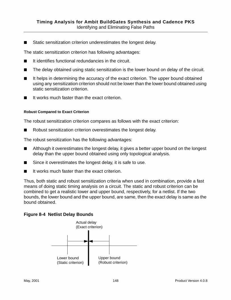
Timing Analysis for Ambit BuildGates Synthesis and Cadence PKSIdentifying and Eliminating False Paths
■ Static sensitization criterion underestimates the longest delay.
The static sensitization criterion has following advantages:
■ It identifies functional redundancies in the circuit.
■ The delay obtained using static sensitization is the lower bound on delay of the circuit.
■ It helps in determining the accuracy of the exact criterion. The upper bound obtainedusing any sensitization criterion should not be lower than the lower bound obtained usingstatic sensitization criterion.
■ It works much faster than the exact criterion.
Robust Compared to Exact Criterion
The robust sensitization criterion compares as follows with the exact criterion:
■ Robust sensitization criterion overestimates the longest delay.
The robust sensitization has the following advantages:
■ Although it overestimates the longest delay, it gives a better upper bound on the longestdelay than the upper bound obtained using only topological analysis.
■ Since it overestimates the longest delay, it is safe to use.
■ It works much faster than the exact criterion.
Thus, both static and robust sensitization criteria when used in combination, provide a fastmeans of doing static timing analysis on a circuit. The static and robust criterion can becombined to get a realistic lower and upper bound, respectively, for a netlist. If the twobounds, the lower bound and the upper bound, are same, then the exact delay is same as thebound obtained.
Figure 8-4 Netlist Delay Bounds
Lower bound(Static criterion)
Upper bound(Robust criterion)
Actual delay(Exact criterion)
May, 2001 148 Product Version 4.0.8
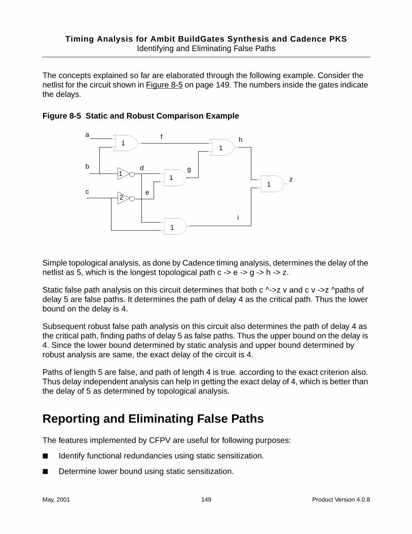
Timing Analysis for Ambit BuildGates Synthesis and Cadence PKSIdentifying and Eliminating False Paths
The concepts explained so far are elaborated through the following example. Consider thenetlist for the circuit shown in Figure 8-5 on page 149. The numbers inside the gates indicatethe delays.
Figure 8-5 Static and Robust Comparison Example
Simple topological analysis, as done by Cadence timing analysis, determines the delay of thenetlist as 5, which is the longest topological path c -> e -> g -> h -> z.
Static false path analysis on this circuit determines that both c ^->z v and c v ->z ^paths ofdelay 5 are false paths. It determines the path of delay 4 as the critical path. Thus the lowerbound on the delay is 4.
Subsequent robust false path analysis on this circuit also determines the path of delay 4 asthe critical path, finding paths of delay 5 as false paths. Thus the upper bound on the delay is4. Since the lower bound determined by static analysis and upper bound determined byrobust analysis are same, the exact delay of the circuit is 4.
Paths of length 5 are false, and path of length 4 is true. according to the exact criterion also.Thus delay independent analysis can help in getting the exact delay of 4, which is better thanthe delay of 5 as determined by topological analysis.
Reporting and Eliminating False Paths
The features implemented by CFPV are useful for following purposes:
■ Identify functional redundancies using static sensitization.
■ Determine lower bound using static sensitization.
1
1
1
1
1a
c
1
2e
b d
f
g
h
i
z
May, 2001 149 Product Version 4.0.8
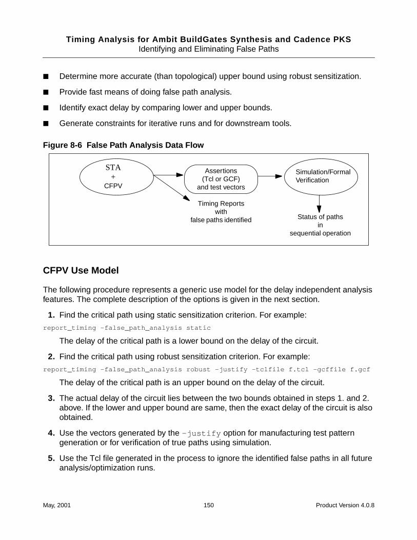
Timing Analysis for Ambit BuildGates Synthesis and Cadence PKSIdentifying and Eliminating False Paths
■ Determine more accurate (than topological) upper bound using robust sensitization.
■ Provide fast means of doing false path analysis.
■ Identify exact delay by comparing lower and upper bounds.
■ Generate constraints for iterative runs and for downstream tools.
Figure 8-6 False Path Analysis Data Flow
CFPV Use Model
The following procedure represents a generic use model for the delay independent analysisfeatures. The complete description of the options is given in the next section.
1. Find the critical path using static sensitization criterion. For example:
report_timing -false_path_analysis static
The delay of the critical path is a lower bound on the delay of the circuit.
2. Find the critical path using robust sensitization criterion. For example:
report_timing -false_path_analysis robust -justify -tclfile f.tcl -gcffile f.gcf
The delay of the critical path is an upper bound on the delay of the circuit.
3. The actual delay of the circuit lies between the two bounds obtained in steps 1. and 2.above. If the lower and upper bound are same, then the exact delay of the circuit is alsoobtained.
4. Use the vectors generated by the -justify option for manufacturing test patterngeneration or for verification of true paths using simulation.
5. Use the Tcl file generated in the process to ignore the identified false paths in all futureanalysis/optimization runs.
STA+
CFPV
Assertions(Tcl or GCF)
and test vectors
Timing Reportswith
false paths identified Status of pathsin
sequential operation
Simulation/FormalVerification
May, 2001 150 Product Version 4.0.8
Timing Analysis for Ambit BuildGates Synthesis and Cadence PKSIdentifying and Eliminating False Paths
6. Use the GCF file generated to specify false paths to downstream tools in backend of thedesign implementation.
Options to report_timing for False Path Analysis
This section describes the options to the report_timing command that you can use forfalse path analysis. These options let you choose the type of analysis (static or robust) andthe type of report file (Tcl or GCF). You can then source these reports to eliminate the falsepaths in subsequent timing analysis, optimization, or layout operations as shown in Figure 8-6on page 150.
-false_path_analysis {static | robust}The -false_path_analysis option determines the status ofa path using static (or robust) analysis. Unless the -true optionis used to disable printing of false paths, a false path is indicatedin the report as shown in this example:
Path 1: FALSE PATH
-justifyUsing the -justify option generates a vector which sensitizesa true path. These vectors are useful in verifying the true pathsusing simulation. These vectors can also be used to generatemanufacturing test patterns for path delay fault detection.
Note: This option can only be used with the -false_path_analysis option.
-trueThe -true option displays all true paths identified. The falsepaths identified are not printed. The sensitization criterion mustbe specified using the -false_path_analysis option.
Note: This option can only be used with the -false_path_analysis option.
-tclfile tclfilenameGenerates a Tcl file, tclfilename , containing Tclset_false_path commands corresponding to the false pathsidentified. An error message is issued if tclfilename is notspecified.
You can source tclfilename before running thereport_timing command again. This filters out the falsepaths from the report and next available true paths are reported.
May, 2001 151 Product Version 4.0.8
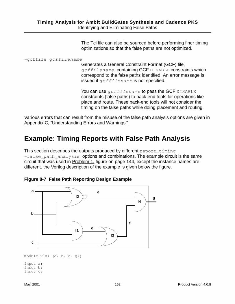
Timing Analysis for Ambit BuildGates Synthesis and Cadence PKSIdentifying and Eliminating False Paths
The Tcl file can also be sourced before performing finer timingoptimizations so that the false paths are not optimized.
-gcffile gcffilenameGenerates a General Constraint Format (GCF) file,gcffilename , containing GCF DISABLE constraints whichcorrespond to the false paths identified. An error message isissued if gcffilename is not specified.
You can use gcffilename to pass the GCF DISABLEconstraints (false paths) to back-end tools for operations likeplace and route. These back-end tools will not consider thetiming on the false paths while doing placement and routing.
Various errors that can result from the misuse of the false path analysis options are given inAppendix C, “Understanding Errors and Warnings.”
Example: Timing Reports with False Path Analysis
This section describes the outputs produced by different report_timing-false_path_analysis options and combinations. The example circuit is the samecircuit that was used in Problem 1. figure on page 144, except the instance names aredifferent. the Verilog description of the example is given below the figure.
Figure 8-7 False Path Reporting Design Example
module vlsi (a, b, c, g);
input a;input b;input c;
a
b
c
e
df
gI2
I1I3
I4
May, 2001 152 Product Version 4.0.8
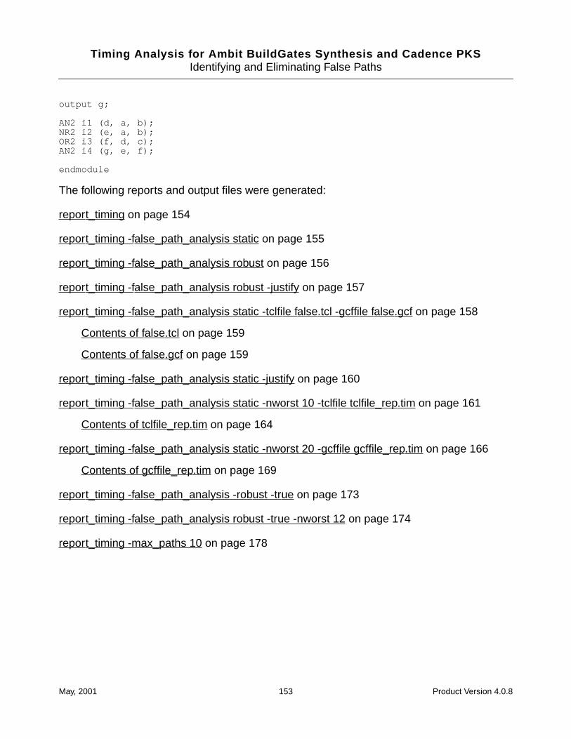
Timing Analysis for Ambit BuildGates Synthesis and Cadence PKSIdentifying and Eliminating False Paths
output g;
AN2 i1 (d, a, b);NR2 i2 (e, a, b);OR2 i3 (f, d, c);AN2 i4 (g, e, f);
endmodule
The following reports and output files were generated:
report_timing on page 154
report_timing -false_path_analysis static on page 155
report_timing -false_path_analysis robust on page 156
report_timing -false_path_analysis robust -justify on page 157
report_timing -false_path_analysis static -tclfile false.tcl -gcffile false.gcf on page 158
Contents of false.tcl on page 159
Contents of false.gcf on page 159
report_timing -false_path_analysis static -justify on page 160
report_timing -false_path_analysis static -nworst 10 -tclfile tclfile_rep.tim on page 161
Contents of tclfile_rep.tim on page 164
report_timing -false_path_analysis static -nworst 20 -gcffile gcffile_rep.tim on page 166
Contents of gcffile_rep.tim on page 169
report_timing -false_path_analysis -robust -true on page 173
report_timing -false_path_analysis robust -true -nworst 12 on page 174
report_timing -max_paths 10 on page 178
May, 2001 153 Product Version 4.0.8
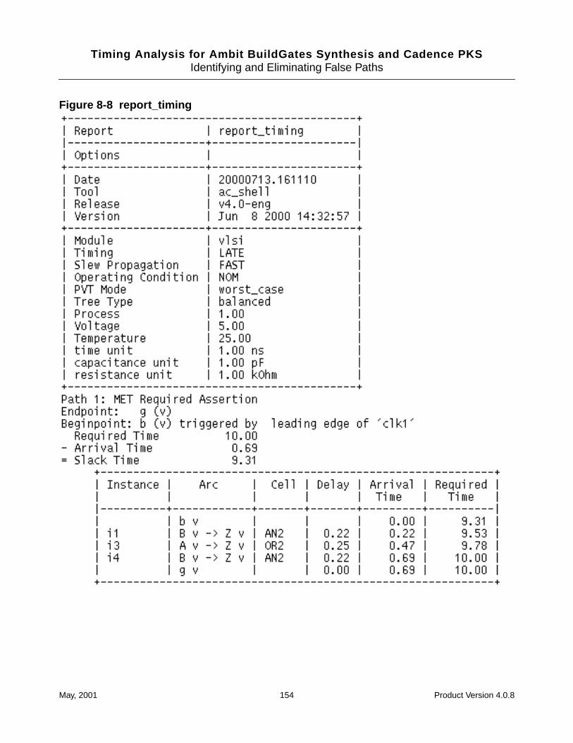
Timing Analysis for Ambit BuildGates Synthesis and Cadence PKSIdentifying and Eliminating False Paths
Figure 8-8 report_timing
May, 2001 154 Product Version 4.0.8

Timing Analysis for Ambit BuildGates Synthesis and Cadence PKSIdentifying and Eliminating False Paths
Figure 8-9 report_timing -false_path_analysis static
May, 2001 155 Product Version 4.0.8

Timing Analysis for Ambit BuildGates Synthesis and Cadence PKSIdentifying and Eliminating False Paths
Figure 8-10 report_timing -false_path_analysis robust
May, 2001 156 Product Version 4.0.8
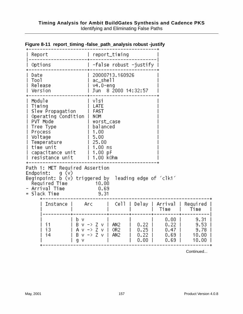
Timing Analysis for Ambit BuildGates Synthesis and Cadence PKSIdentifying and Eliminating False Paths
Figure 8-11 report_timing -false_path_analysis robust -justify
Continued...
May, 2001 157 Product Version 4.0.8
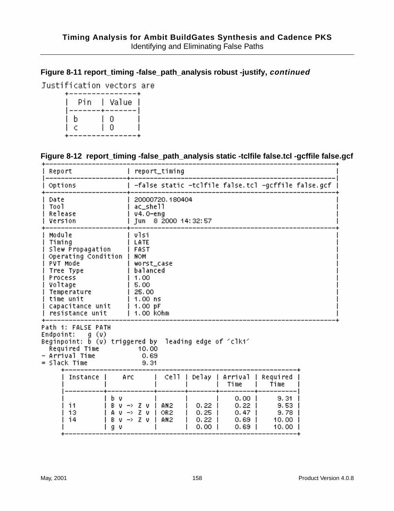
Timing Analysis for Ambit BuildGates Synthesis and Cadence PKSIdentifying and Eliminating False Paths
Figure 8-11 report_timing -false_path_analysis robust -justify, continued
Figure 8-12 report_timing -false_path_analysis static -tclfile false.tcl -gcffile false.gcf
May, 2001 158 Product Version 4.0.8
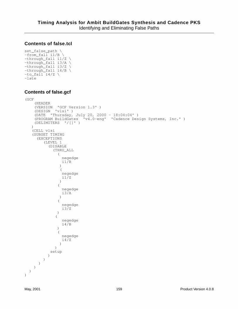
Timing Analysis for Ambit BuildGates Synthesis and Cadence PKSIdentifying and Eliminating False Paths
Contents of false.tclset_false_path \-from_fall i1/B \-through_fall i1/Z \-through_fall i3/A \-through_fall i3/Z \-through_fall i4/B \-to_fall i4/Z \-late
Contents of false.gcf(GCF
(HEADER(VERSION "GCF Version 1.3" )(DESIGN "vlsi" )(DATE "Thursday, July 20, 2000 - 18:04:04" )(PROGRAM BuildGates "v4.0-eng" "Cadence Design Systems, Inc." )(DELIMITERS "/[]" )
)(CELL vlsi(SUBSET TIMING
(EXCEPTIONS(LEVEL 1
(DISABLE(THRU_ALL
(negedgei1/B
)(
negedgei1/Z
)(
negedgei3/A
)(
negedgei3/Z
)(
negedgei4/B
)(
negedgei4/Z
))
setup)
))
))
)
May, 2001 159 Product Version 4.0.8

Timing Analysis for Ambit BuildGates Synthesis and Cadence PKSIdentifying and Eliminating False Paths
Figure 8-13 report_timing -false_path_analysis static -justify
May, 2001 160 Product Version 4.0.8
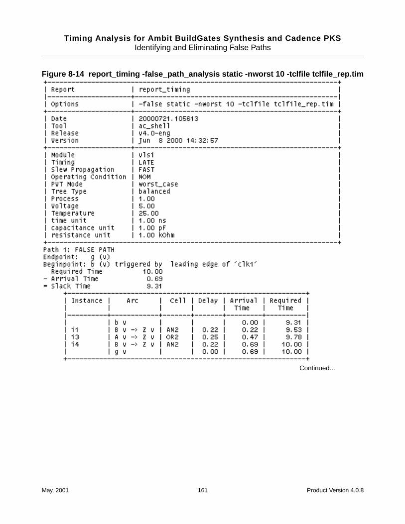
Timing Analysis for Ambit BuildGates Synthesis and Cadence PKSIdentifying and Eliminating False Paths
Figure 8-14 report_timing -false_path_analysis static -nworst 10 -tclfile tclfile_rep.tim
Continued...
May, 2001 161 Product Version 4.0.8
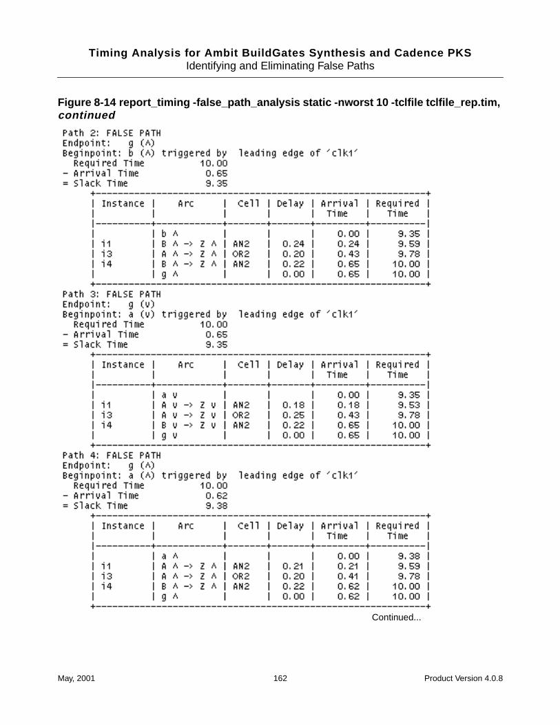
Timing Analysis for Ambit BuildGates Synthesis and Cadence PKSIdentifying and Eliminating False Paths
Figure 8-14 report_timing -false_path_analysis static -nworst 10 -tclfile tclfile_rep.tim,continued
Continued...
May, 2001 162 Product Version 4.0.8
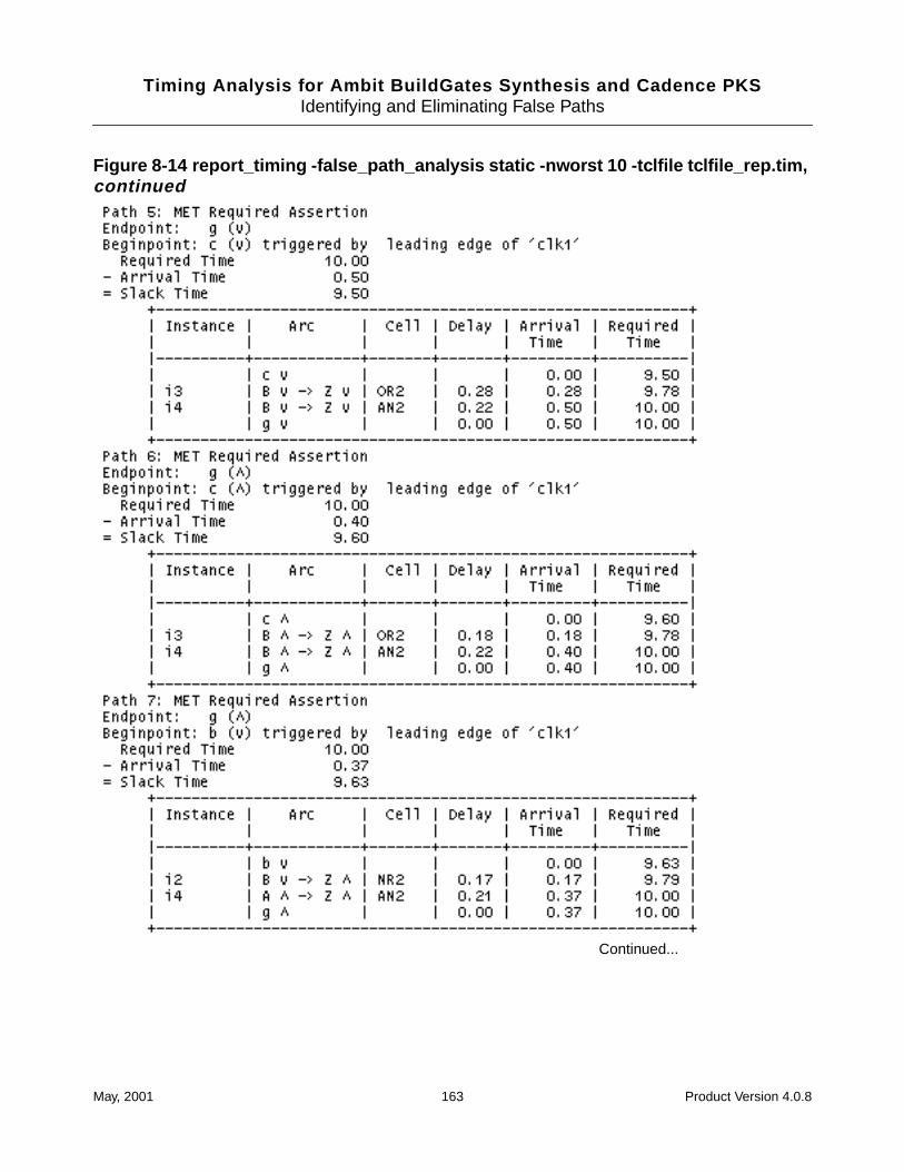
Timing Analysis for Ambit BuildGates Synthesis and Cadence PKSIdentifying and Eliminating False Paths
Figure 8-14 report_timing -false_path_analysis static -nworst 10 -tclfile tclfile_rep.tim,continued
Continued...
May, 2001 163 Product Version 4.0.8
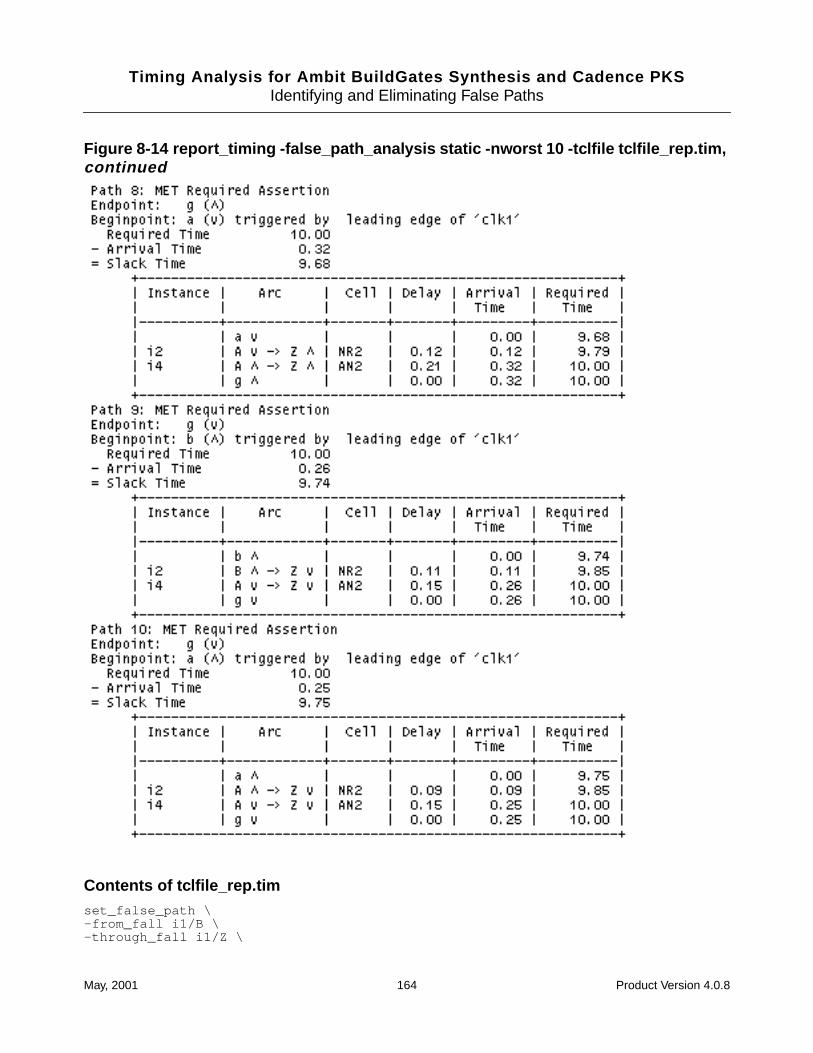
Timing Analysis for Ambit BuildGates Synthesis and Cadence PKSIdentifying and Eliminating False Paths
Figure 8-14 report_timing -false_path_analysis static -nworst 10 -tclfile tclfile_rep.tim,continued
Contents of tclfile_rep.timset_false_path \-from_fall i1/B \-through_fall i1/Z \
May, 2001 164 Product Version 4.0.8
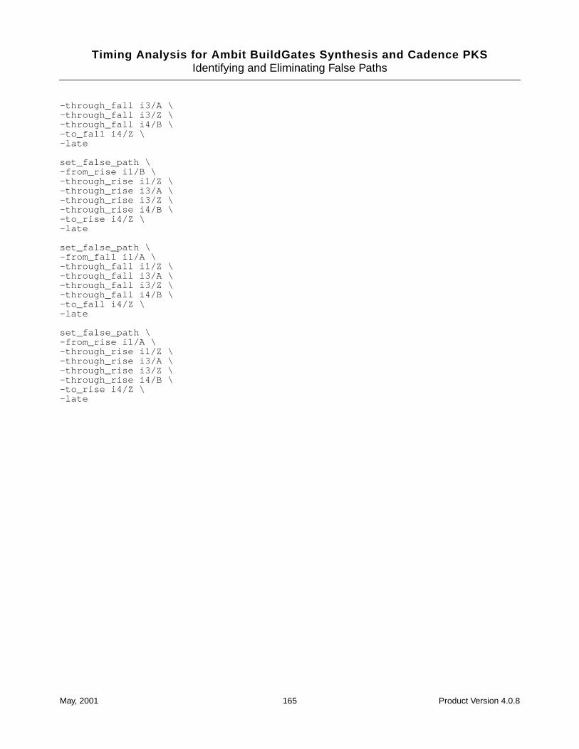
Timing Analysis for Ambit BuildGates Synthesis and Cadence PKSIdentifying and Eliminating False Paths
-through_fall i3/A \-through_fall i3/Z \-through_fall i4/B \-to_fall i4/Z \-late
set_false_path \-from_rise i1/B \-through_rise i1/Z \-through_rise i3/A \-through_rise i3/Z \-through_rise i4/B \-to_rise i4/Z \-late
set_false_path \-from_fall i1/A \-through_fall i1/Z \-through_fall i3/A \-through_fall i3/Z \-through_fall i4/B \-to_fall i4/Z \-late
set_false_path \-from_rise i1/A \-through_rise i1/Z \-through_rise i3/A \-through_rise i3/Z \-through_rise i4/B \-to_rise i4/Z \-late
May, 2001 165 Product Version 4.0.8
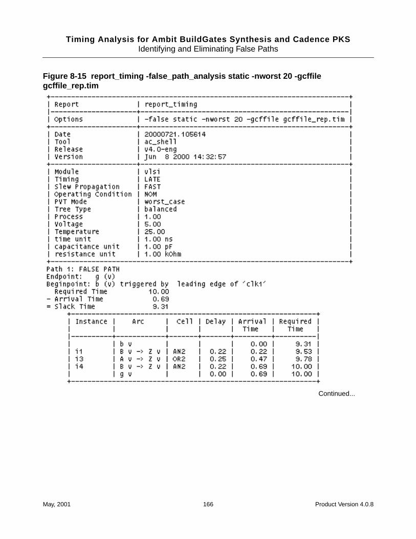
Timing Analysis for Ambit BuildGates Synthesis and Cadence PKSIdentifying and Eliminating False Paths
Figure 8-15 report_timing -false_path_analysis static -nworst 20 -gcffilegcffile_rep.tim
Continued...
May, 2001 166 Product Version 4.0.8
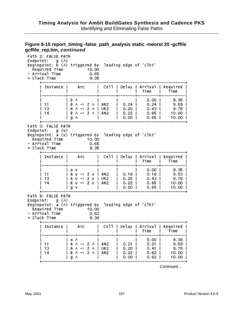
Timing Analysis for Ambit BuildGates Synthesis and Cadence PKSIdentifying and Eliminating False Paths
Figure 8-15 report_timing -false_path_analysis static -nworst 20 -gcffilegcffile_rep.tim, continued
Continued...
May, 2001 167 Product Version 4.0.8
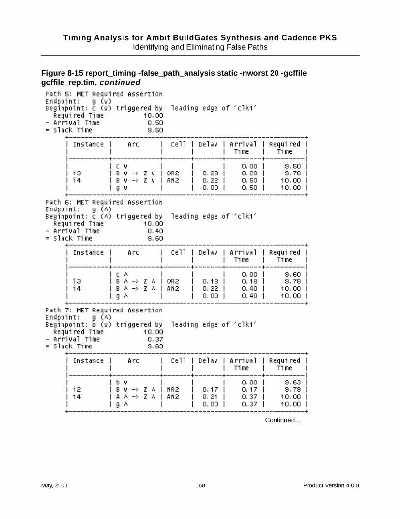
Timing Analysis for Ambit BuildGates Synthesis and Cadence PKSIdentifying and Eliminating False Paths
Figure 8-15 report_timing -false_path_analysis static -nworst 20 -gcffilegcffile_rep.tim, continued
Continued...
May, 2001 168 Product Version 4.0.8
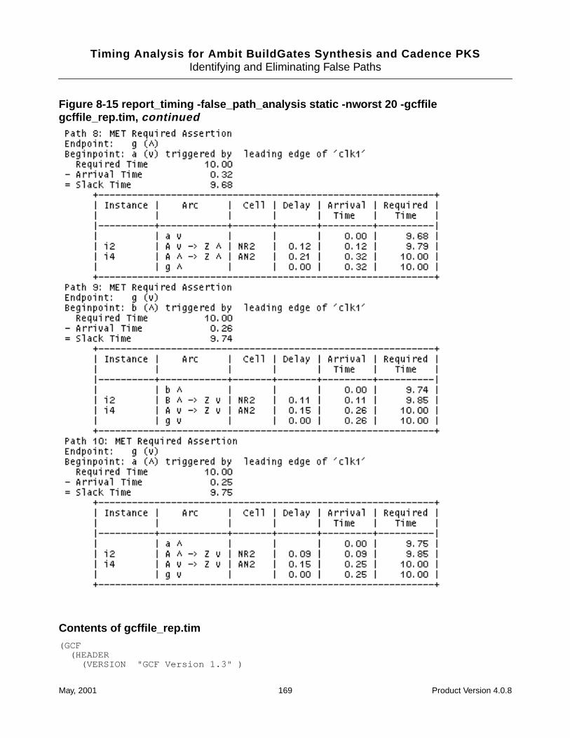
Timing Analysis for Ambit BuildGates Synthesis and Cadence PKSIdentifying and Eliminating False Paths
Figure 8-15 report_timing -false_path_analysis static -nworst 20 -gcffilegcffile_rep.tim, continued
Contents of gcffile_rep.tim(GCF
(HEADER(VERSION "GCF Version 1.3" )
May, 2001 169 Product Version 4.0.8
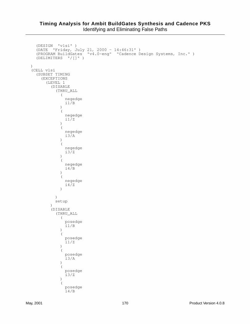
Timing Analysis for Ambit BuildGates Synthesis and Cadence PKSIdentifying and Eliminating False Paths
(DESIGN "vlsi" )(DATE "Friday, July 21, 2000 - 14:46:31" )(PROGRAM BuildGates "v4.0-eng" "Cadence Design Systems, Inc." )(DELIMITERS "/[]" )
)(CELL vlsi
(SUBSET TIMING(EXCEPTIONS
(LEVEL 1(DISABLE
(THRU_ALL(
negedgei1/B
)(
negedgei1/Z
)(
negedgei3/A
)(
negedgei3/Z
)(
negedgei4/B
)(
negedgei4/Z
)
)setup
)(DISABLE
(THRU_ALL(
posedgei1/B
)(
posedgei1/Z
)(
posedgei3/A
)(
posedgei3/Z
)(
posedgei4/B
May, 2001 170 Product Version 4.0.8
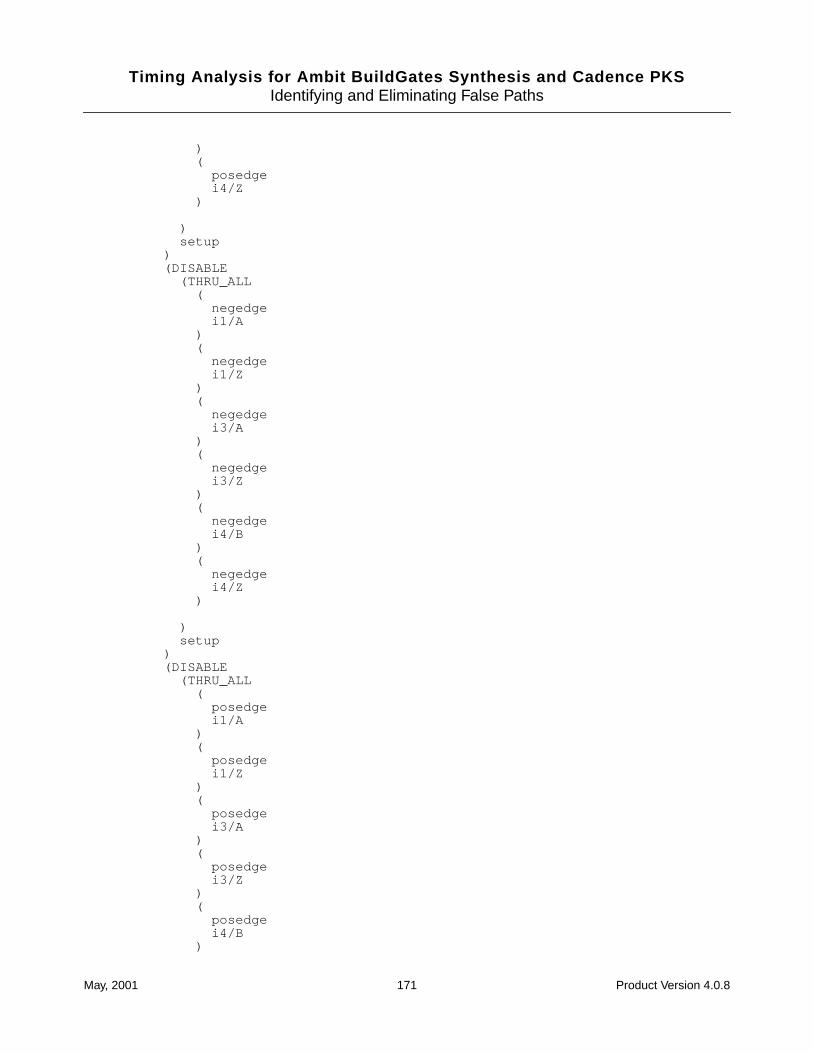
Timing Analysis for Ambit BuildGates Synthesis and Cadence PKSIdentifying and Eliminating False Paths
)(
posedgei4/Z
)
)setup
)(DISABLE
(THRU_ALL(
negedgei1/A
)(
negedgei1/Z
)(
negedgei3/A
)(
negedgei3/Z
)(
negedgei4/B
)(
negedgei4/Z
)
)setup
)(DISABLE
(THRU_ALL(
posedgei1/A
)(
posedgei1/Z
)(
posedgei3/A
)(
posedgei3/Z
)(
posedgei4/B
)
May, 2001 171 Product Version 4.0.8
Timing Analysis for Ambit BuildGates Synthesis and Cadence PKSIdentifying and Eliminating False Paths
(posedgei4/Z
)
)setup
)
)
)
)
)
)
May, 2001 172 Product Version 4.0.8
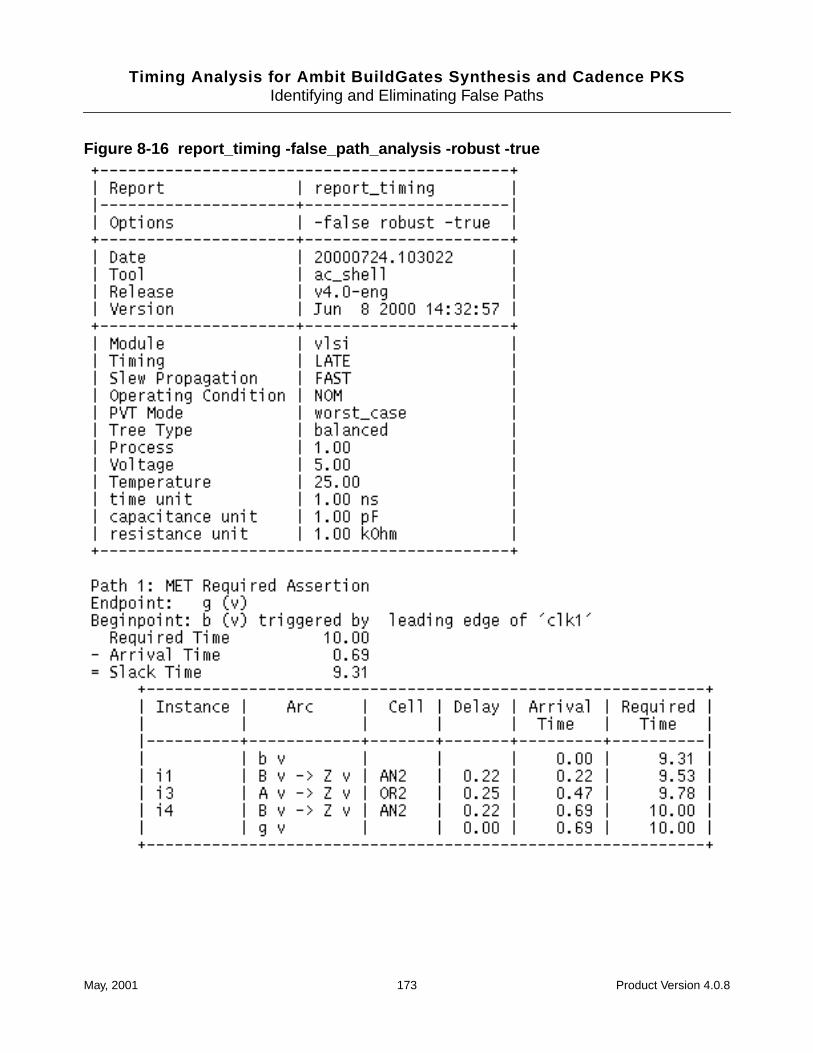
Timing Analysis for Ambit BuildGates Synthesis and Cadence PKSIdentifying and Eliminating False Paths
Figure 8-16 report_timing -false_path_analysis -robust -true
May, 2001 173 Product Version 4.0.8
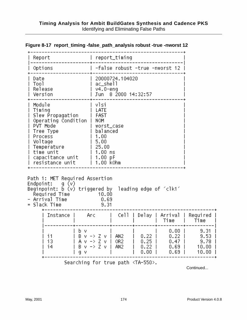
Timing Analysis for Ambit BuildGates Synthesis and Cadence PKSIdentifying and Eliminating False Paths
Figure 8-17 report_timing -false_path_analysis robust -true -nworst 12
Continued...
May, 2001 174 Product Version 4.0.8
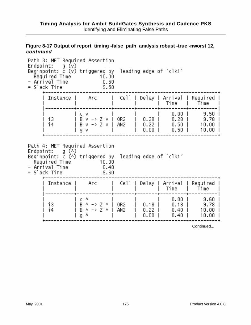
Timing Analysis for Ambit BuildGates Synthesis and Cadence PKSIdentifying and Eliminating False Paths
Figure 8-17 Output of report_timing -false_path_analysis robust -true -nworst 12,continued
Continued...
May, 2001 175 Product Version 4.0.8
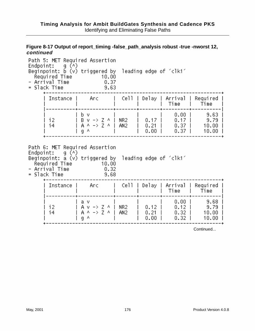
Timing Analysis for Ambit BuildGates Synthesis and Cadence PKSIdentifying and Eliminating False Paths
Figure 8-17 Output of report_timing -false_path_analysis robust -true -nworst 12,continued
Continued...
May, 2001 176 Product Version 4.0.8
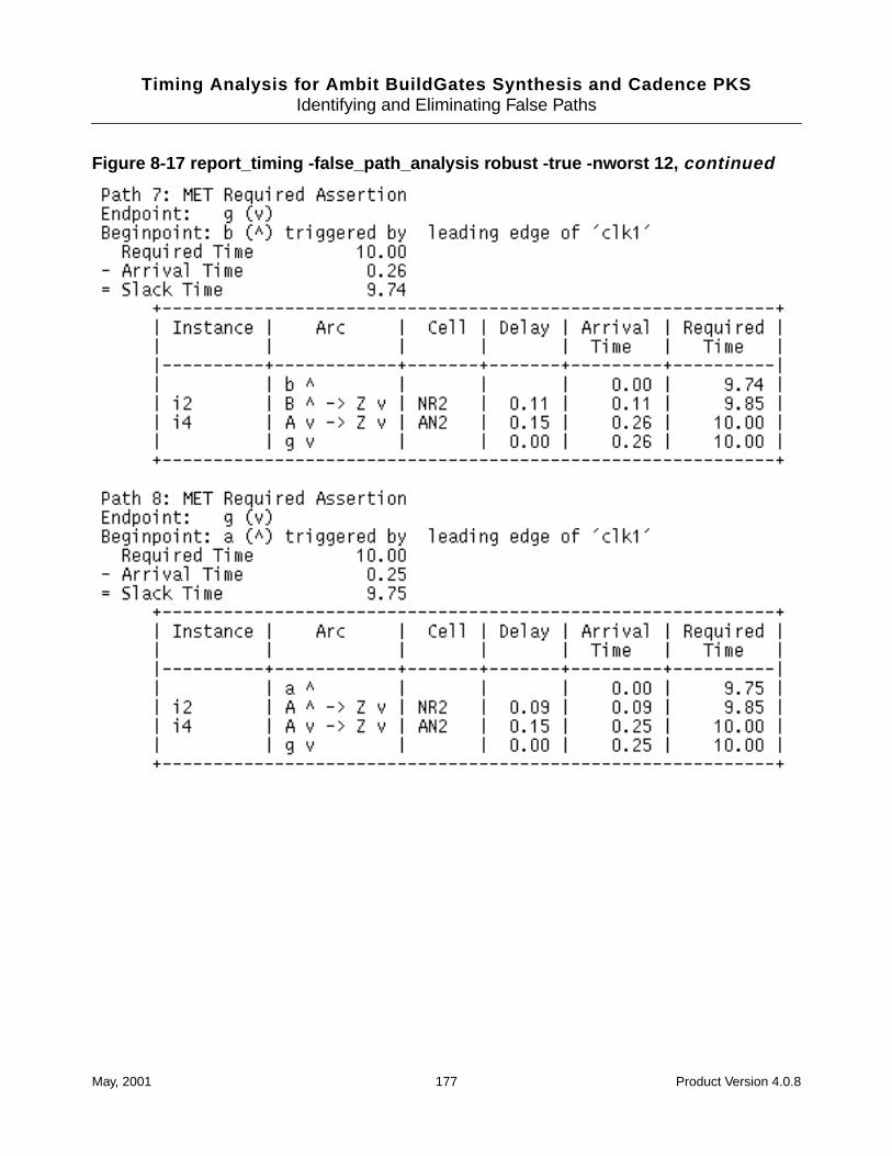
Timing Analysis for Ambit BuildGates Synthesis and Cadence PKSIdentifying and Eliminating False Paths
Figure 8-17 report_timing -false_path_analysis robust -true -nworst 12, continued
May, 2001 177 Product Version 4.0.8
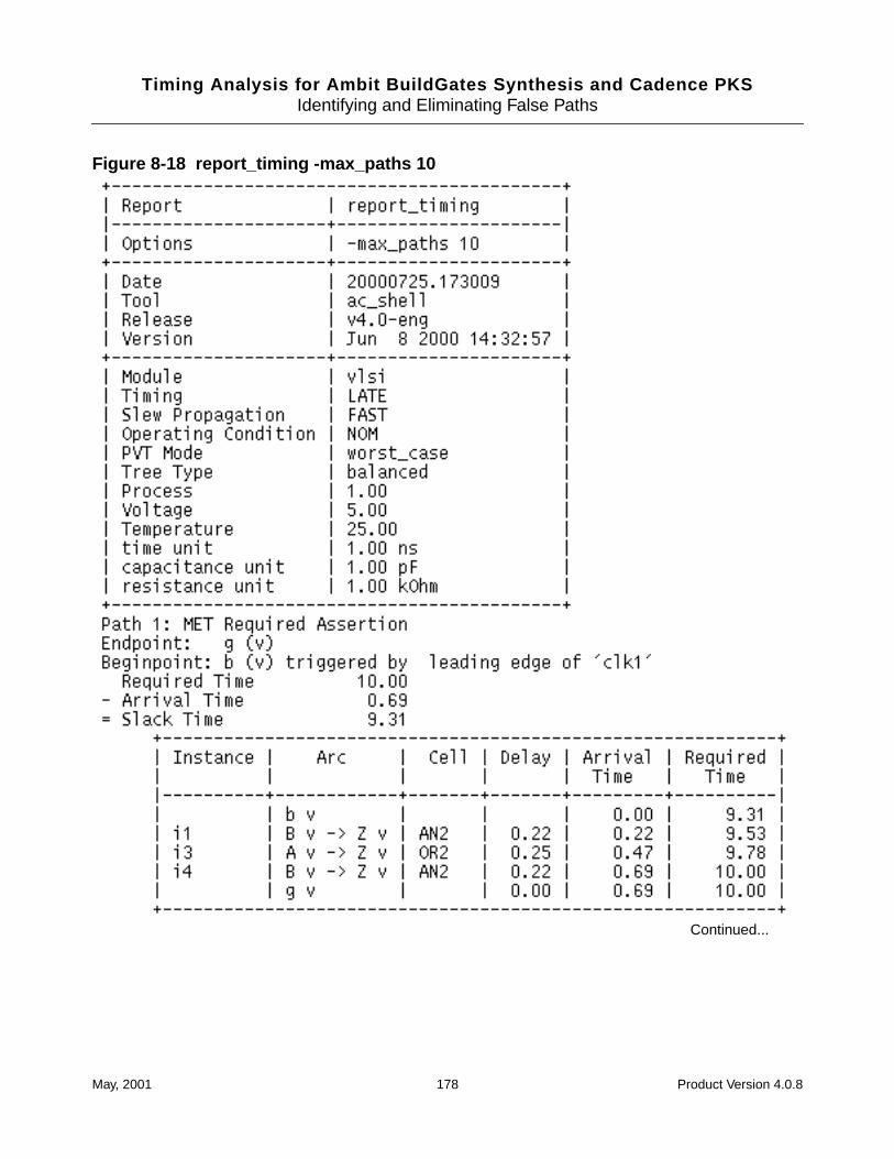
Timing Analysis for Ambit BuildGates Synthesis and Cadence PKSIdentifying and Eliminating False Paths
Figure 8-18 report_timing -max_paths 10
Continued...
May, 2001 178 Product Version 4.0.8
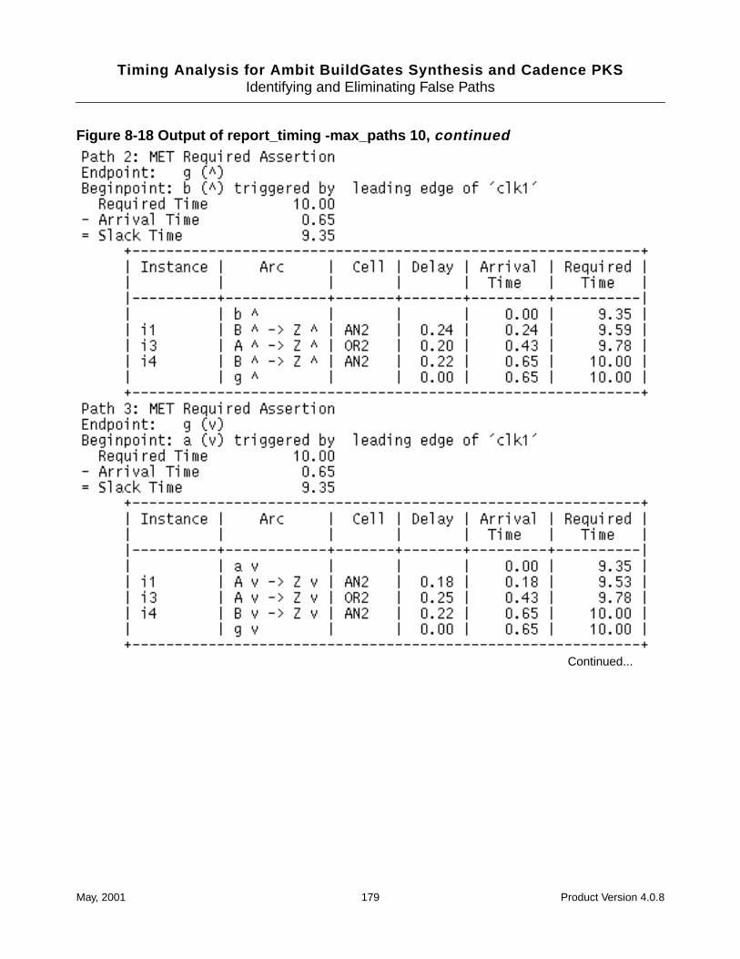
Timing Analysis for Ambit BuildGates Synthesis and Cadence PKSIdentifying and Eliminating False Paths
Figure 8-18 Output of report_timing -max_paths 10, continued
Continued...
May, 2001 179 Product Version 4.0.8
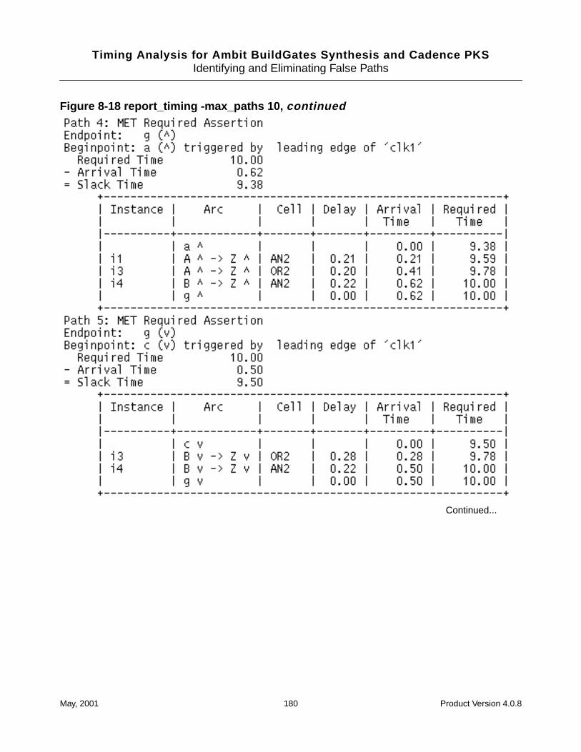
Timing Analysis for Ambit BuildGates Synthesis and Cadence PKSIdentifying and Eliminating False Paths
Figure 8-18 report_timing -max_paths 10, continued
Continued...
May, 2001 180 Product Version 4.0.8
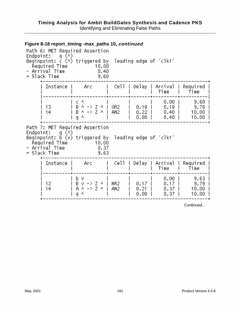
Timing Analysis for Ambit BuildGates Synthesis and Cadence PKSIdentifying and Eliminating False Paths
Figure 8-18 report_timing -max_paths 10, continued
Continued...
May, 2001 181 Product Version 4.0.8

Timing Analysis for Ambit BuildGates Synthesis and Cadence PKSIdentifying and Eliminating False Paths
Figure 8-18 report_timing -max_paths 10, continued
Continued...
May, 2001 182 Product Version 4.0.8
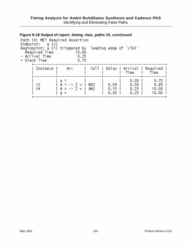
Timing Analysis for Ambit BuildGates Synthesis and Cadence PKSIdentifying and Eliminating False Paths
Figure 8-18 Output of report_timing -max_paths 10, continued
May, 2001 183 Product Version 4.0.8

Timing Analysis for Ambit BuildGates Synthesis and Cadence PKSIdentifying and Eliminating False Paths
May, 2001 184 Product Version 4.0.8
Timing Analysis for Ambit BuildGates Synthesis and Cadence PKS
9Finding and Fixing Violations
This chapter contains information to help you complete timing analysis with no violations. Thefollowing topics are covered:
■ Finding Violations on page 186
■ Setting Path Exceptions on page 186
May, 2001 185 Product Version 4.0.8
Timing Analysis for Ambit BuildGates Synthesis and Cadence PKSFinding and Fixing Violations
Finding Violations
Violations are contained in the output report from report_timing . However many of thesereported violations may not be actual violations. Often the first task in debugging your designis to eliminate false violations from the report. Once you have found the true violations, youcan fix them.
Many reported violations can be eliminated by the correct use of path exceptions. The pathexceptions are:
■ False path
A false path is one that will never be used. The violation will never actually occur.
■ Path delay constraint
■ Cycle addition
Some path violations are reported because proper analysis requires more than one clockcycle. By default, STA uses one clock cycle for analysis. You can eliminate this kind ofviolation by adding cycles on the path.
Setting Path Exceptions
Specifying False Paths
For a complete method of determining and specifying false paths, see Chapter 8, “Identifyingand Eliminating False Paths.”
If you want to set a false path for debugging purposes, see set_false_path in theCommand Reference for Ambit BuildGates Synthesis and Cadence PKS.
Specifying Path Delay Constraints
You can set a maximum or minimum travel time limit for signals traveling along specific pathsin the design. The set_path_delay_constraint command is used for this purpose. Forlate paths, this command sets a maximum limit on path delays in order for setup constraintsto be satisfied. For early paths, the command sets a minimum limit on path delays in order forhold constraints to be satisfied.
Note: The set_path_delay_constraint command is equivalent to theset_max_delay and set_min_delay commands from dc_shell and pt_shell .
May, 2001 186 Product Version 4.0.8
Timing Analysis for Ambit BuildGates Synthesis and Cadence PKSFinding and Fixing Violations
➤ To specify a path delay constraint, use the set_path_delay_constraint commandas shown in this example:
set_path_delay_constraint -from I_block/A_reg/Q 2.0
Note: Before you use set_path_delay_constraint , the globalpath_style_timing_constraint must be set to true which is the default value.
The syntax is like set_false_path with the addition of a delay value. Seeset_path_delay_constraint in the Command Reference for Ambit BuildGatesSynthesis and Cadence PKS. Any path that matches the parameters given (from/through/to, and so on) is constrained by the set_path_delay_constraint command. Onlyset_false_path has priority over the set_path_delay_constraint , andset_path_delay_constraint commands are prioritized with each other the same wayset_cycle_addition is. See Path Exception Priorities table on page 188.
There are two types of path delays:
■ Sequential
A sequential path starts/ends at a register or latch primary IO. Setting a path delayconstraint on a sequential path is similar to adjusting the cycle time. This lets you tightenor relax the cycle-time requirements on given paths.
■ Combinational
A combinational path starts/ends at anything other than register or latch primary IOs.
Sequential Path Delays
The effect of a sequential path delay constraint is similar to changing the cycle time. Here ishow the slack is calculated:
late slack = (early arrival time of capturing clock) - (setup, uncertainty, external delay, etc.)+ (the late path delay constraint) - (late arrival time of data at endpoint)
early slack = (early arrival time of data at endpoint) - (late arrival time of capturing clock)- (hold, uncertainty, external delay, etc.) - (the early path delay constraint)
Note: The clocks, uncertainty, setup/hold, and other constraints are considered. The onlydifference you should notice is the “phase shift” change with the path delay constraint.
May, 2001 187 Product Version 4.0.8
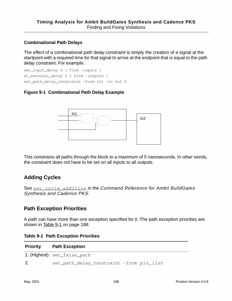
Timing Analysis for Ambit BuildGates Synthesis and Cadence PKSFinding and Fixing Violations
Combinational Path Delays
The effect of a combinational path delay constraint is simply the creation of a signal at thestartpoint with a required time for that signal to arrive at the endpoint that is equal to the pathdelay constraint. For example:
set_input_delay 0 [ find -inputs ]
et_external_delay 0 [ find -outputs ]
set_path_delay_constraint -from In1 -to In2 5
Figure 9-1 Combinational Path Delay Example
This constrains all paths through the block to a maximum of 5 nanoseconds. In other words,the constraint does not have to be set on all inputs to all outputs.
Adding Cycles
See set_cycle_addition in the Command Reference for Ambit BuildGatesSynthesis and Cadence PKS.
Path Exception Priorities
A path can have more than one exception specified for it. The path exception priorities areshown in Table 9-1 on page 188.
Table 9-1 Path Exception Priorities
Priority Path Exception
1. (Highest) set_false_path
2. set_path_delay_constraint -from pin_list
In1In2
May, 2001 188 Product Version 4.0.8
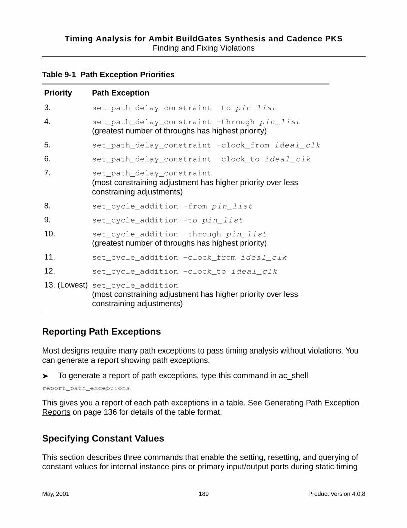
Timing Analysis for Ambit BuildGates Synthesis and Cadence PKSFinding and Fixing Violations
Reporting Path Exceptions
Most designs require many path exceptions to pass timing analysis without violations. Youcan generate a report showing path exceptions.
➤ To generate a report of path exceptions, type this command in ac_shell
report_path_exceptions
This gives you a report of each path exceptions in a table. See Generating Path ExceptionReports on page 136 for details of the table format.
Specifying Constant Values
This section describes three commands that enable the setting, resetting, and querying ofconstant values for internal instance pins or primary input/output ports during static timing
3. set_path_delay_constraint -to pin_list
4. set_path_delay_constraint -through pin_list(greatest number of throughs has highest priority)
5. set_path_delay_constraint -clock_from ideal_clk
6. set_path_delay_constraint -clock_to ideal_clk
7. set_path_delay_constraint(most constraining adjustment has higher priority over lessconstraining adjustments)
8. set_cycle_addition -from pin_list
9. set_cycle_addition -to pin_list
10. set_cycle_addition -through pin_list(greatest number of throughs has highest priority)
11. set_cycle_addition -clock_from ideal_clk
12. set_cycle_addition -clock_to ideal_clk
13. (Lowest) set_cycle_addition(most constraining adjustment has higher priority over lessconstraining adjustments)
Table 9-1 Path Exception Priorities
Priority Path Exception
May, 2001 189 Product Version 4.0.8
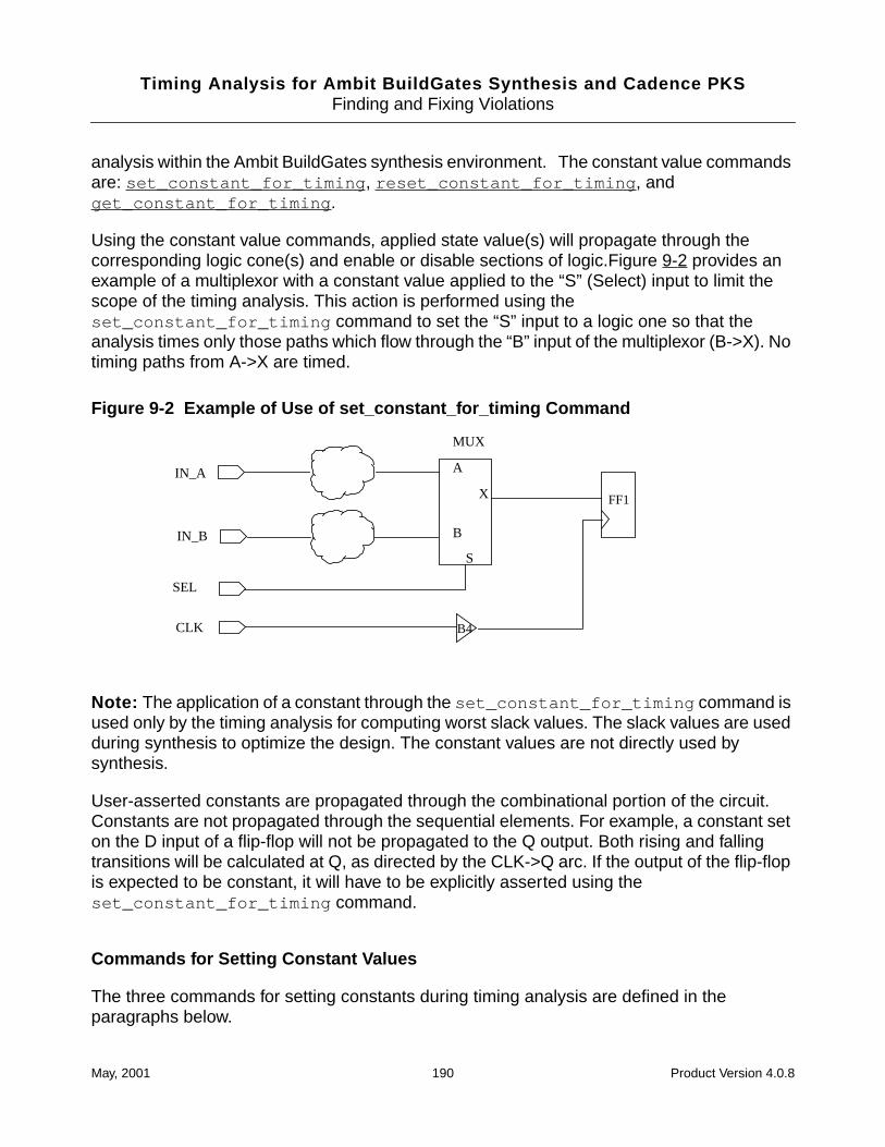
Timing Analysis for Ambit BuildGates Synthesis and Cadence PKSFinding and Fixing Violations
analysis within the Ambit BuildGates synthesis environment. The constant value commandsare: set_constant_for_timing , reset_constant_for_timing , andget_constant_for_timing .
Using the constant value commands, applied state value(s) will propagate through thecorresponding logic cone(s) and enable or disable sections of logic.Figure 9-2 provides anexample of a multiplexor with a constant value applied to the “S” (Select) input to limit thescope of the timing analysis. This action is performed using theset_constant_for_timing command to set the “S” input to a logic one so that theanalysis times only those paths which flow through the “B” input of the multiplexor (B->X). Notiming paths from A->X are timed.
Figure 9-2 Example of Use of set_constant_for_timing Command
Note: The application of a constant through the set_constant_for_timing command isused only by the timing analysis for computing worst slack values. The slack values are usedduring synthesis to optimize the design. The constant values are not directly used bysynthesis.
User-asserted constants are propagated through the combinational portion of the circuit.Constants are not propagated through the sequential elements. For example, a constant seton the D input of a flip-flop will not be propagated to the Q output. Both rising and fallingtransitions will be calculated at Q, as directed by the CLK->Q arc. If the output of the flip-flopis expected to be constant, it will have to be explicitly asserted using theset_constant_for_timing command.
Commands for Setting Constant Values
The three commands for setting constants during timing analysis are defined in theparagraphs below.
FF1
CLK B4
S
MUX
A
B
X
SEL
IN_A
IN_B
May, 2001 190 Product Version 4.0.8
Timing Analysis for Ambit BuildGates Synthesis and Cadence PKSFinding and Fixing Violations
Note: Constant values are saved to the .adb file when using the command write_adb(refer to the Command Reference for Ambit BuildGates Synthesis and Cadence PKS.)
set_constant_for_timing {0|1} list_of_pins
The set_constant_for_timing command applies a 1 or 0 value to the specified pin(s)for use by the timing engine. Multiple pins may be specified by passing a space-separated pinlist (standard Tcl list variable).
reset_constant_for_timing list_of_pins
The reset_constant_for_timing command removes previously asserted constants onthe specified pin(s). Once a constant is reset, the timing engine goes back to analyzing thesystem by calculating and propagating the arrival times (and in turn computing the requiredtimes) at the pin(s).
get_constant_for_timing pin_name
The get_constant_for_timing command queries the design database for the constantthat has been set on a pin or propagated through the logic cone to that pin. This commanddoes not work for hierarchical pins.
Example Script of Constants Used in Timing Analysis
The following script shows constants being used in the context of timing analysis.
Read timing libraries
set TargetTech [read_alf stdcell_wccom.alf]
set_global target_technology $TargetTech
set_operating_condition WORST_CASE
# load design
read_verilog chip.v
do_build_generic
set_top_timing_module chip
set_current_module chip
# Set up timing constraints on the design
source TimingConstraints.tcl
report_timing
set_constant_for_timing 1 i4/A
report_timing
May, 2001 191 Product Version 4.0.8

Timing Analysis for Ambit BuildGates Synthesis and Cadence PKSFinding and Fixing Violations
May, 2001 192 Product Version 4.0.8

Timing Analysis for Ambit BuildGates Synthesis and Cadence PKS
10Using Advanced Analysis Techniques
This chapter discusses the following advanced analysis topics:
■ Using RAM and ROM Models on page 194
■ Analyzing Latch-based Designs on page 200
■ On and Off Chip Variation Analysis on page 212
■ Common Path Pessimism Removal on page 216
May, 2001 193 Product Version 4.0.8
Timing Analysis for Ambit BuildGates Synthesis and Cadence PKSUsing Advanced Analysis Techniques
Using RAM and ROM Models
This section describes the use of RAM and ROM models in Cadence timing analysis. Thecurrent model used is subject to change with future releases. This section discusses onlyRAM elements for brevity. ROM elements are treated in a similar fashion.
Using RAM and ROM Models In Logic Optimization
In the past, synthesis users were faced with the restriction of being able to build only thesmallest, leaf-level building blocks within a single pass of logic optimization. These buildingblocks were typically on the order of 3000-5000 gates. Synthesis users designing logic blockswhich interfaced to or from RAM elements would typically synthesize these logic blocks inindependent optimizations, without the RAM cell being instantiated in the block beingoptimized. Synthesizing designs in this fashion became time-consuming as the designer hadto manually control the optimization of the logic interfacing to the RAM element. Furthermore,the designer usually had to then verify proper timing operation via an external static timingverification environment.
With the advent of hierarchical synthesis and the ability to synthesize increasing amounts oflogic, the scope of the logic optimization may be expanded to include the RAM element withinthe hierarchical block being synthesized. That is not to say that the RAM element should bedissolved into the surrounding control logic. The approach here is to leave the RAMinstantiated at the same level as the instantiation of all logic blocks that interface to it.Hierarchical synthesis with the RAM (included as one of the logic blocks) clearly providesbetter ease-of-use as the designer does not have to spend the effort in manually developingexternal budgets for all logic blocks that interface to the RAM.
An alternate approach is to leave the RAM instance(s) at the top-level and derive the timingcontext for all modules that interface to them. For more details, refer to Chapter 6, “Derivingthe Timing Context for a Module.” When deriving the timing context for all logic blocks, timinganalysis times all paths through a RAM object. Cadence timing analysis supports theextraction of time-budgeted information around the RAM objects. This timing contextinformation can then be used, along with hierarchical synthesis, on all design objects thatinterface to the RAM.
The choice as to whether or not to perform hierarchical synthesis with the included RAM isoften a function of such technology issues as:
■ Does the vendor require that the RAM model be instantiated at the top-most level of thehierarchy?
■ Is the floor planning information accurately reflected in the wireload estimates for thenets that interface to the RAM?
May, 2001 194 Product Version 4.0.8
Timing Analysis for Ambit BuildGates Synthesis and Cadence PKSUsing Advanced Analysis Techniques
■ Would the area of RAM element corrupt the auto-wireload selection such that unrealisticwireload estimates would be obtained for top-level nets?
Importing RAM and ROM Models Into Synthesis
RAM models supplied by the silicon vendor are typically auto-generated via a memorycompiler program. Cadence timing analysis reads the format generated by these compilers.The RAM model may or may not contain a library header. If a library header is present, theRAM model should first be compiled into a stand-alone library; refer to Chapter 2, “Choosinga Methodology.” for more details. This library may then be added to the link library path usingthe read_adb command. If the generated RAM model does not contain a library header, itis a stand-alone cell definition. This cell definition can be used directly, without the need tofirst compile it into a stand-alone library. The cell definition is appended to the current link (andtarget) libraries via the use of the read_library_update command. The target technologymust be set prior to the use of the read_library_update command.
Cadence timing analysis automatically considers all timing arcs through the RAM elementwhen performing timing analysis. For an asynchronous RAM, the timing arc from the writeenable input MUST include the timing_type keyword, particularly if a clock is propagatedto or specified directly on the write enable input. Timing analysis does not automaticallydeduce the sense of the write enable based upon analysis of timing arcs associated with it.Example 8-1 shows a sample portion of an asynchronous RAM model. There is no libraryheader information. Instead a cell definition exists by itself, thus this model is a stand-alonecell definition that can be used with the read_library_update command.
Output pin DOA contains timing arcs from input pins AADR3, AADR2, AADR1, AADR0, OEA,WEC, and DIC. All of these timing arcs are considered when performing timing analysis. Inputpin WEC is the write enable input. Note that the timing arc from the WEC pin to the DOAoutput contains a timing_type: rising_edge ; statement. This statement is necessaryfor timing analysis to understand the clocked nature of this input pin and to block thepropagation of the clock through the RAM element. Note that the definition of the WEC pinitself includes only direction and capacitance keywords. Input pin DIC is a data input pin witha setup and hold constraint relative to the falling edge of the WEC input.
Before attempting to do timing analysis on circuits with RAM models, you should take the timeto review the RAM model in detail to understand if it conforms to the suggested format listedbelow.
A Simple RAM Cell Script/*
************************************************************
Standard Header - Generated by.....
May, 2001 195 Product Version 4.0.8
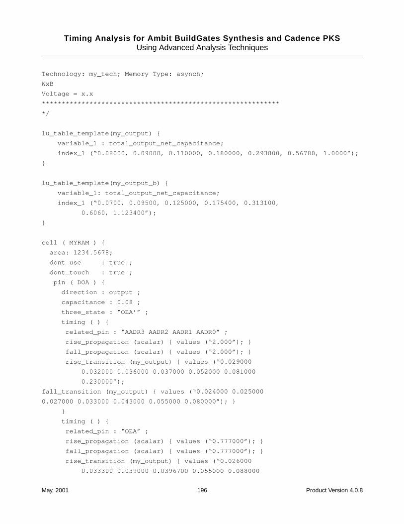
Timing Analysis for Ambit BuildGates Synthesis and Cadence PKSUsing Advanced Analysis Techniques
Technology: my_tech; Memory Type: asynch;
WxB
Voltage = x.x
************************************************************
*/
lu_table_template(my_output) {
variable_1 : total_output_net_capacitance;
index_1 (“0.08000, 0.09000, 0.110000, 0.180000, 0.293800, 0.56780, 1.0000”);
}
lu_table_template(my_output_b) {
variable_1: total_output_net_capacitance;
index_1 (“0.0700, 0.09500, 0.125000, 0.175400, 0.313100,
0.6060, 1.123400”);
}
cell ( MYRAM ) {
area: 1234.5678;
dont_use : true ;
dont_touch : true ;
pin ( DOA ) {
direction : output ;
capacitance : 0.08 ;
three_state : “OEA’” ;
timing ( ) {
related_pin : “AADR3 AADR2 AADR1 AADR0” ;
rise_propagation (scalar) { values (“2.000”); }
fall_propagation (scalar) { values (“2.000”); }
rise_transition (my_output) { values (“0.029000
0.032000 0.036000 0.037000 0.052000 0.081000
0.230000”);
fall_transition (my_output) { values (“0.024000 0.025000
0.027000 0.033000 0.043000 0.055000 0.080000”); }
}
timing ( ) {
related_pin : “OEA” ;
rise_propagation (scalar) { values (“0.777000”); }
fall_propagation (scalar) { values (“0.777000”); }
rise_transition (my_output) { values (“0.026000
0.033300 0.039000 0.0396700 0.055000 0.088000
May, 2001 196 Product Version 4.0.8
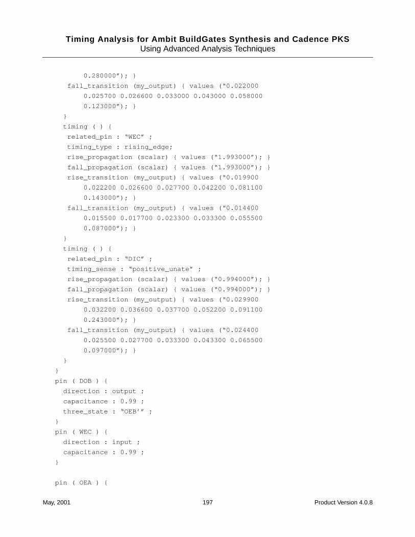
Timing Analysis for Ambit BuildGates Synthesis and Cadence PKSUsing Advanced Analysis Techniques
0.280000”); }
fall_transition (my_output) { values (“0.022000
0.025700 0.026600 0.033000 0.043000 0.058000
0.123000”); }
}
timing ( ) {
related_pin : “WEC” ;
timing_type : rising_edge;
rise_propagation (scalar) { values (“1.993000”); }
fall_propagation (scalar) { values (“1.993000”); }
rise_transition (my_output) { values (“0.019900
0.022200 0.026600 0.027700 0.042200 0.081100
0.143000”); }
fall_transition (my_output) { values (“0.014400
0.015500 0.017700 0.023300 0.033300 0.055500
0.087000”); }
}
timing ( ) {
related_pin : “DIC” ;
timing_sense : “positive_unate” ;
rise_propagation (scalar) { values (“0.994000”); }
fall_propagation (scalar) { values (“0.994000”); }
rise_transition (my_output) { values (“0.029900
0.032200 0.036600 0.037700 0.052200 0.091100
0.243000”); }
fall_transition (my_output) { values (“0.024400
0.025500 0.027700 0.033300 0.043300 0.065500
0.097000”); }
}
}
pin ( DOB ) {
direction : output ;
capacitance : 0.99 ;
three_state : “OEB’” ;
}
pin ( WEC ) {
direction : input ;
capacitance : 0.99 ;
}
pin ( OEA ) {
May, 2001 197 Product Version 4.0.8
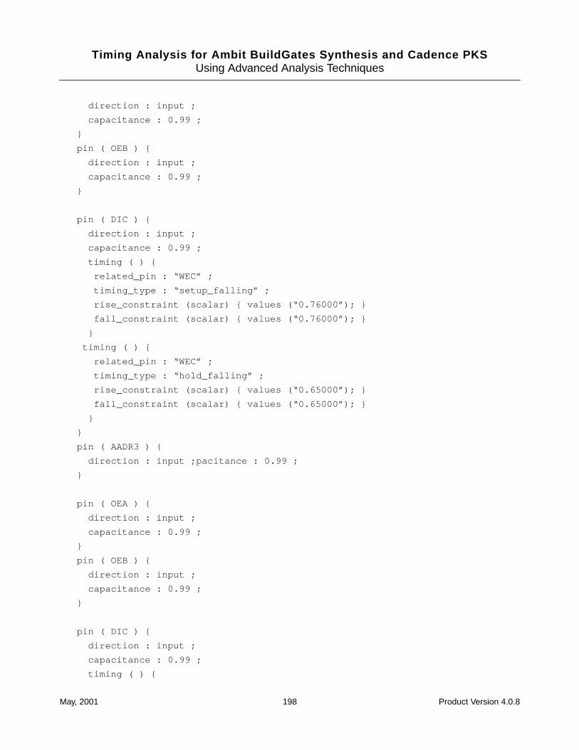
Timing Analysis for Ambit BuildGates Synthesis and Cadence PKSUsing Advanced Analysis Techniques
direction : input ;
capacitance : 0.99 ;
}
pin ( OEB ) {
direction : input ;
capacitance : 0.99 ;
}
pin ( DIC ) {
direction : input ;
capacitance : 0.99 ;
timing ( ) {
related_pin : “WEC” ;
timing_type : “setup_falling” ;
rise_constraint (scalar) { values (“0.76000”); }
fall_constraint (scalar) { values (“0.76000”); }
}
timing ( ) {
related_pin : “WEC” ;
timing_type : “hold_falling” ;
rise_constraint (scalar) { values (“0.65000”); }
fall_constraint (scalar) { values (“0.65000”); }
}
}
pin ( AADR3 ) {
direction : input ;pacitance : 0.99 ;
}
pin ( OEA ) {
direction : input ;
capacitance : 0.99 ;
}
pin ( OEB ) {
direction : input ;
capacitance : 0.99 ;
}
pin ( DIC ) {
direction : input ;
capacitance : 0.99 ;
timing ( ) {
May, 2001 198 Product Version 4.0.8
Timing Analysis for Ambit BuildGates Synthesis and Cadence PKSUsing Advanced Analysis Techniques
related_pin : “WEC” ;
timing_type : “setup_falling” ;
rise_constraint (scalar) { values (“0.76000”); }
fall_constraint (scalar) { values (“0.76000”); }
}
timing ( ) {
related_pin : “WEC” ;
timing_type : “hold_falling” ;
rise_constraint (scalar) { values (“0.65000”); }
fall_constraint (scalar) { values (“0.65000”); }
}
capacitance : 0.89 ;
}
pin ( AADR2 ) {
direction : input ;
capacitance : 0.89 ;
}
pin ( AADR1 ) {
direction : input ;
capacitance : 0.89 ;
}
pin ( AADR0 ) {
direction : input ;
capacitance : 0.89 ;
}
May, 2001 199 Product Version 4.0.8
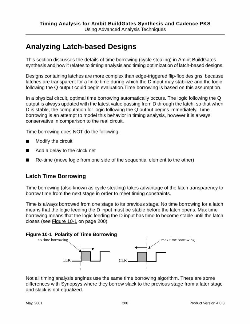
Timing Analysis for Ambit BuildGates Synthesis and Cadence PKSUsing Advanced Analysis Techniques
Analyzing Latch-based Designs
This section discusses the details of time borrowing (cycle stealing) in Ambit BuildGatessynthesis and how it relates to timing analysis and timing optimization of latch-based designs.
Designs containing latches are more complex than edge-triggered flip-flop designs, becauselatches are transparent for a finite time during which the D input may stabilize and the logicfollowing the Q output could begin evaluation.Time borrowing is based on this assumption.
In a physical circuit, optimal time borrowing automatically occurs. The logic following the Qoutput is always updated with the latest value passing from D through the latch, so that whenD is stable, the computation for logic following the Q output begins immediately. Timeborrowing is an attempt to model this behavior in timing analysis, however it is alwaysconservative in comparison to the real circuit.
Time borrowing does NOT do the following:
■ Modify the circuit
■ Add a delay to the clock net
■ Re-time (move logic from one side of the sequential element to the other)
Latch Time Borrowing
Time borrowing (also known as cycle stealing) takes advantage of the latch transparency toborrow time from the next stage in order to meet timing constraints.
Time is always borrowed from one stage to its previous stage. No time borrowing for a latchmeans that the logic feeding the D input must be stable before the latch opens. Max timeborrowing means that the logic feeding the D input has time to become stable until the latchcloses (see Figure 10-1 on page 200).
Figure 10-1 Polarity of Time Borrowing
Not all timing analysis engines use the same time borrowing algorithm. There are somedifferences with Synopsys where they borrow slack to the previous stage from a later stageand slack is not equalized.
no time borrowing max time borrowing
CLK CLK
May, 2001 200 Product Version 4.0.8
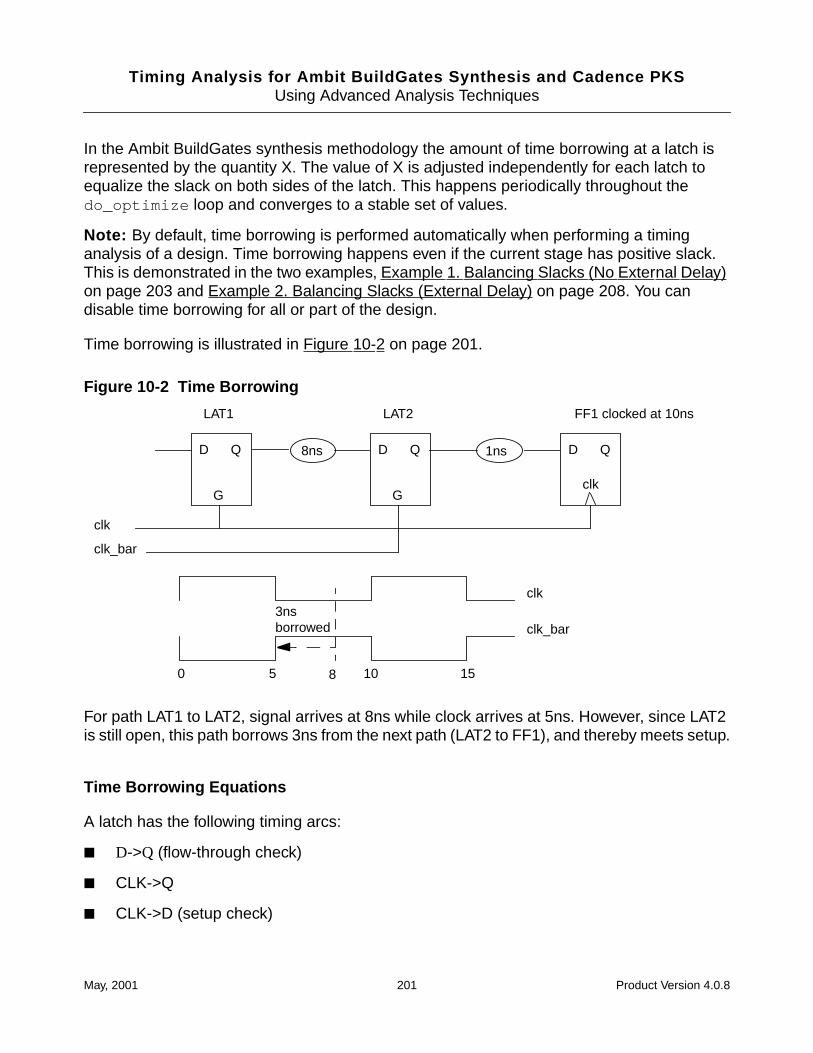
Timing Analysis for Ambit BuildGates Synthesis and Cadence PKSUsing Advanced Analysis Techniques
In the Ambit BuildGates synthesis methodology the amount of time borrowing at a latch isrepresented by the quantity X. The value of X is adjusted independently for each latch toequalize the slack on both sides of the latch. This happens periodically throughout thedo_optimize loop and converges to a stable set of values.
Note: By default, time borrowing is performed automatically when performing a timinganalysis of a design. Time borrowing happens even if the current stage has positive slack.This is demonstrated in the two examples, Example 1. Balancing Slacks (No External Delay)on page 203 and Example 2. Balancing Slacks (External Delay) on page 208. You candisable time borrowing for all or part of the design.
Time borrowing is illustrated in Figure 10-2 on page 201.
Figure 10-2 Time Borrowing
For path LAT1 to LAT2, signal arrives at 8ns while clock arrives at 5ns. However, since LAT2is still open, this path borrows 3ns from the next path (LAT2 to FF1), and thereby meets setup.
Time Borrowing Equations
A latch has the following timing arcs:
■ D->Q (flow-through check)
■ CLK->Q
■ CLK->D (setup check)
D Q
G
D Q
G
D Q
clk
8ns 1ns
LAT1 LAT2 FF1 clocked at 10ns
clk
clk_bar
clk
clk_bar
0 5 10 158
3nsborrowed
May, 2001 201 Product Version 4.0.8
Timing Analysis for Ambit BuildGates Synthesis and Cadence PKSUsing Advanced Analysis Techniques
In this discussion, the amount of time borrowing is indicated by X.
Each timing arc has separate rising, falling, propagation, and transition delays. In Cadencetiming analysis methodology the setup check from the closing edge of the clock (CLK) to theD input is always performed. This check determines the maximum limit on time-borrowing.The required time for input D that corresponds to the maximum time-borrowing situation isdenoted by RTsetup(D), which is calculated by equation.
When the amount of time borrowing is less than its maximum value, the required time forinput D, denoted by RT(D), is earlier than RTsetup(D). A loop-check now replaces the flow-through check from D-> Q (the arc is ‘cut’).
The new arrival time (AT) at Q is calculated in the following equation where X is the amountof time borrowed:
The loop-check determines how late D can be factored in, if the arrival time at Q is allowed toslip by some amount X, without causing the D->Q flow-through delay to be worse than thatarrival time at Q. The equation for loop check delay is:
The new required time (RT) at D becomes: RT(D) = CLK(opening) + loop check delay or
Hence the larger the value of X, the greater the required time at D, and the greater the arrivaltime at Q. The maximum value of X is the value that gives the same RT as the RTsetup.
(10-1) RTsetup(D) = CLK(closing) - Latch setup time = CLK(closing) - CLK->D
(10-2) AT(Q) = CLK(opening) + CLK -> Q + X
(10-3) Loop check delay = X - D -> Q + CLK -> Q
(10-4) RT(D) = CLK(opening) + X - D -> Q + CLK -> Q
(10-5) RTsetup(D) = RT(D) for Max X
(10-6) CLK(closing) - CLK->D(setup) = CLK(opening) + Max X - D -> Q + CLK -> Q
May, 2001 202 Product Version 4.0.8
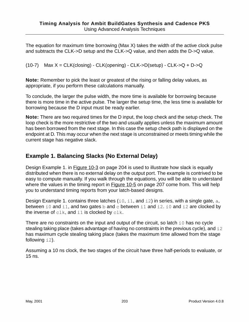
Timing Analysis for Ambit BuildGates Synthesis and Cadence PKSUsing Advanced Analysis Techniques
The equation for maximum time borrowing (Max X) takes the width of the active clock pulseand subtracts the CLK->D setup and the CLK->Q value, and then adds the D->Q value.
Note: Remember to pick the least or greatest of the rising or falling delay values, asappropriate, if you perform these calculations manually.
To conclude, the larger the pulse width, the more time is available for borrowing becausethere is more time in the active pulse. The larger the setup time, the less time is available forborrowing because the D input must be ready earlier.
Note: There are two required times for the D input, the loop check and the setup check. Theloop check is the more restrictive of the two and usually applies unless the maximum amounthas been borrowed from the next stage. In this case the setup check path is displayed on theendpoint at D. This may occur when the next stage is unconstrained or meets timing while thecurrent stage has negative slack.
Example 1. Balancing Slacks (No External Delay)
Design Example 1. in Figure 10-3 on page 204 is used to illustrate how slack is equallydistributed when there is no external delay on the output port. The example is contrived to beeasy to compute manually. If you walk through the equations, you will be able to understandwhere the values in the timing report in Figure 10-5 on page 207 come from. This will helpyou to understand timing reports from your latch-based designs.
Design Example 1. contains three latches (i0 , i1 , and i2 ) in series, with a single gate, a,between i0 and i1 , and two gates b and c between i1 and i2 . i0 and i2 are clocked bythe inverse of clk , and i1 is clocked by clk .
There are no constraints on the input and output of the circuit, so latch i0 has no cyclestealing taking place (takes advantage of having no constraints in the previous cycle), and i2has maximum cycle stealing taking place (takes the maximum time allowed from the stagefollowing i2 ).
Assuming a 10 ns clock, the two stages of the circuit have three half-periods to evaluate, or15 ns.
(10-7) Max X = CLK(closing) - CLK(opening) - CLK->D(setup) - CLK->Q + D->Q
May, 2001 203 Product Version 4.0.8
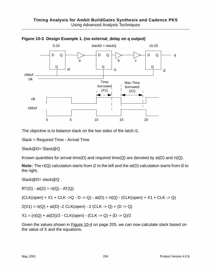
Timing Analysis for Ambit BuildGates Synthesis and Cadence PKSUsing Advanced Analysis Techniques
Figure 10-3 Design Example 1. (no external_delay on q output)
The objective is to balance slack on the two sides of the latch i1.
Slack = Required Time - Arrival Time
Slack@D= Slack@Q
Known quantities for arrival time(D) and required time(Q) are denoted by at(D) and rt(Q).
Note: The rt(Q) calculation starts from i2 to the left and the at(D) calculation starts from i0 tothe right.
Slack@D= slack@Q
RT(D) - at(D) = rt(Q) - AT(Q)
(CLK(open) + X1 + CLK ->Q - D -> Q) - at(D) = rt(Q) - (CLK(open) + X1 + CLK -> Q)
2(X1) = rt(Q) + at(D) -2 CLK(open) - 2 (CLK -> Q) + (D -> Q)
X1 = (rt(Q) + at(D))/2 - CLK(open) - (CLK -> Q) + (D -> Q)/2
Given the values shown in Figure 10-4 on page 205, we can now calculate slack based onthe value of X and the equations.
D Q
G
D Q
G
D Q
G
5-10 slackD = slackQ 15-20
clk
clkbuf
clkbufclk
0 5 10 15
Timeborrowed
(X1)
q
20
Max Timeborrowed
(X2)
i0 i1 i2
a b c
May, 2001 204 Product Version 4.0.8
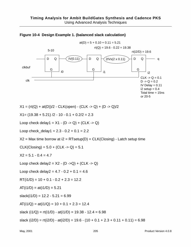
Timing Analysis for Ambit BuildGates Synthesis and Cadence PKSUsing Advanced Analysis Techniques
Figure 10-4 Design Example 1. (balanced slack calculation)
X1 = (rt(Q) + at(D))/2 - CLK(open) - (CLK -> Q) + (D -> Q)/2
X1= (19.38 + 5.21) /2 - 10 - 0.1 + 0.2/2 = 2.3
Loop check delay1 = X1 - (D -> Q) + (CLK -> Q)
Loop check_delay1 = 2.3 - 0.2 + 0.1 = 2.2
X2 = Max time borrow at i2 = RTsetup(D) = CLK(Closing) - Latch setup time
CLK(Closing) = 5.0 + (CLK -> Q) = 5.1
X2 = 5.1 - 0.4 = 4.7
Loop check delay2 = X2 - (D ->Q) + (CLK -> Q)
Loop check delay2 = 4.7 - 0.2 + 0.1 = 4.6
RT(i1/D) = 10 + 0.1 - 0.2 + 2.3 = 12.2
AT(i1/D) = at(i1/D) = 5.21
slack(i1/D) = 12.2 - 5.21 = 6.99
AT(i1/Q) = at(i1/Q) = 10 + 0.1 + 2.3 = 12.4
slack (i1/Q) = rt(i1/D) - at(i1/D) = 19.38 - 12.4 = 6.98
slack (i2/D) = rt(i2/D) - at(i2/D) = 19.6 - (10 + 0.1 + 2.3 + 0.11 + 0.11) = 6.98
2IVs(2 x 0.11)IV(0.11) D Q
G
D Q
G
D Q
G
5-10
at(D) = 5 + 0.10 + 0.11 = 5.21
rt(i2/D) = 19.6
clkbuf
clk
q
i0 i1 i2
rt(Q) = 19.6 - 0.22 = 19.38
CLK -> Q = 0.1D -> Q = 0.2IV Delay = 0.11i2 setup = 0.4Total time = 15nsor 20-5
May, 2001 205 Product Version 4.0.8
Timing Analysis for Ambit BuildGates Synthesis and Cadence PKSUsing Advanced Analysis Techniques
Thus the balanced slack is 6.98 for both paths.
Understanding the Timing Report
The timing report is given in Figure 10-5 on page 207. Here are a few things you should beaware of when reading the timing report:
■ The report shown gives i1/Q to 12/D as Path 1. Because the slacks on the two paths areequal, either could be displayed as Path 1, the path with worst slack.
■ The timing report shows the slack as 6.99 instead of 6.98 due to round-off in the report.
■ The amount of time borrowed, X, is not reported directly.
➤ To determine the amount of time borrowed, use the following equation, where Xrepresents the time borrowed and |Loop Check Delay| is the absolute value of LoopCheck Delay from the timing report:
X = |Loop Check Delay| + (D -> Q) - (CLK -> Q)
For example, in the report in Figure 10-5 on page 207,
X1 = |2.2| + 0.10 = 2.3 and X2 = |-4.60| + 0.10 = 4.7.
The negative polarity of the loop check in the report means that time is borrowed from thenext stage and given to the previous stage.
May, 2001 206 Product Version 4.0.8
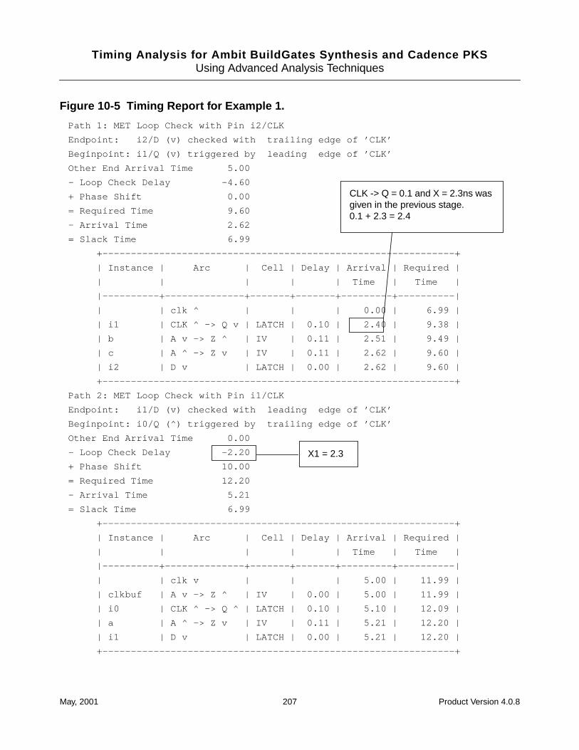
Timing Analysis for Ambit BuildGates Synthesis and Cadence PKSUsing Advanced Analysis Techniques
Figure 10-5 Timing Report for Example 1.
Path 1: MET Loop Check with Pin i2/CLK
Endpoint: i2/D (v) checked with trailing edge of ’CLK’
Beginpoint: i1/Q (v) triggered by leading edge of ’CLK’
Other End Arrival Time 5.00
- Loop Check Delay -4.60
+ Phase Shift 0.00
= Required Time 9.60
- Arrival Time 2.62
= Slack Time 6.99
+--------------------------------------------------------------+
| Instance | Arc | Cell | Delay | Arrival | Required |
| | | | | Time | Time |
|----------+--------------+-------+-------+---------+----------|
| | clk ^ | | | 0.00 | 6.99 |
| i1 | CLK ^ -> Q v | LATCH | 0.10 | 2.40 | 9.38 |
| b | A v -> Z ^ | IV | 0.11 | 2.51 | 9.49 |
| c | A ^ -> Z v | IV | 0.11 | 2.62 | 9.60 |
| i2 | D v | LATCH | 0.00 | 2.62 | 9.60 |
+--------------------------------------------------------------+
Path 2: MET Loop Check with Pin i1/CLK
Endpoint: i1/D (v) checked with leading edge of ’CLK’
Beginpoint: i0/Q (^) triggered by trailing edge of ’CLK’
Other End Arrival Time 0.00
- Loop Check Delay -2.20
+ Phase Shift 10.00
= Required Time 12.20
- Arrival Time 5.21
= Slack Time 6.99
+--------------------------------------------------------------+
| Instance | Arc | Cell | Delay | Arrival | Required |
| | | | | Time | Time |
|----------+--------------+-------+-------+---------+----------|
| | clk v | | | 5.00 | 11.99 |
| clkbuf | A v -> Z ^ | IV | 0.00 | 5.00 | 11.99 |
| i0 | CLK ^ -> Q ^ | LATCH | 0.10 | 5.10 | 12.09 |
| a | A ^ -> Z v | IV | 0.11 | 5.21 | 12.20 |
| i1 | D v | LATCH | 0.00 | 5.21 | 12.20 |
+--------------------------------------------------------------+
CLK -> Q = 0.1 and X = 2.3ns wasgiven in the previous stage.0.1 + 2.3 = 2.4
X1 = 2.3
May, 2001 207 Product Version 4.0.8
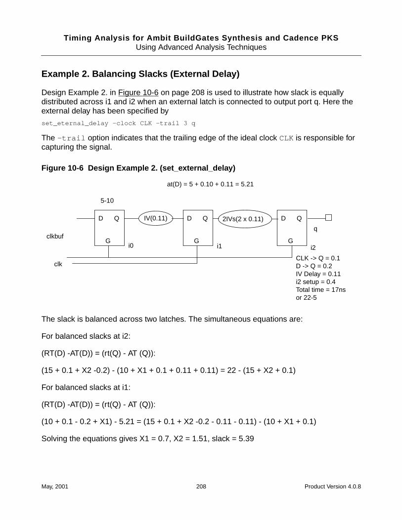
Timing Analysis for Ambit BuildGates Synthesis and Cadence PKSUsing Advanced Analysis Techniques
Example 2. Balancing Slacks (External Delay)
Design Example 2. in Figure 10-6 on page 208 is used to illustrate how slack is equallydistributed across i1 and i2 when an external latch is connected to output port q. Here theexternal delay has been specified by
set_eternal_delay -clock CLK -trail 3 q
The -trail option indicates that the trailing edge of the ideal clock CLK is responsible forcapturing the signal.
Figure 10-6 Design Example 2. (set_external_delay)
The slack is balanced across two latches. The simultaneous equations are:
For balanced slacks at i2:
(RT(D) -AT(D)) = (rt(Q) - AT (Q)):
(15 + 0.1 + X2 -0.2) - (10 + X1 + 0.1 + 0.11 + 0.11) = 22 - (15 + X2 + 0.1)
For balanced slacks at i1:
(RT(D) -AT(D)) = (rt(Q) - AT (Q)):
(10 + 0.1 - 0.2 + X1) - 5.21 = (15 + 0.1 + X2 -0.2 - 0.11 - 0.11) - (10 + X1 + 0.1)
Solving the equations gives X1 = 0.7, X2 = 1.51, slack = 5.39
2IVs(2 x 0.11)IV(0.11) D Q
G
D Q
G
D Q
G
5-10
at(D) = 5 + 0.10 + 0.11 = 5.21
clkbuf
clk
q
i0 i1 i2
CLK -> Q = 0.1D -> Q = 0.2IV Delay = 0.11i2 setup = 0.4Total time = 17nsor 22-5
May, 2001 208 Product Version 4.0.8
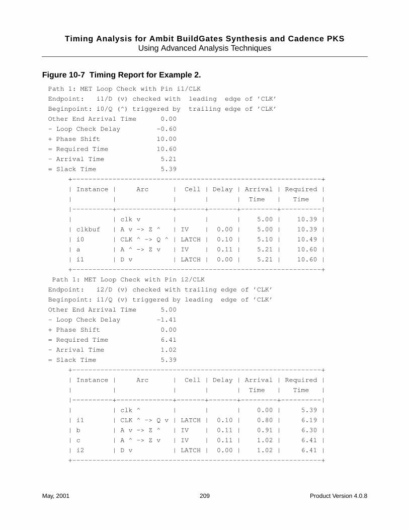
Timing Analysis for Ambit BuildGates Synthesis and Cadence PKSUsing Advanced Analysis Techniques
Figure 10-7 Timing Report for Example 2.
Path 1: MET Loop Check with Pin i1/CLK
Endpoint: i1/D (v) checked with leading edge of ’CLK’
Beginpoint: i0/Q (^) triggered by trailing edge of ’CLK’
Other End Arrival Time 0.00
- Loop Check Delay -0.60
+ Phase Shift 10.00
= Required Time 10.60
- Arrival Time 5.21
= Slack Time 5.39
+--------------------------------------------------------------+
| Instance | Arc | Cell | Delay | Arrival | Required |
| | | | | Time | Time |
|----------+--------------+-------+-------+---------+----------|
| | clk v | | | 5.00 | 10.39 |
| clkbuf | A v -> Z ^ | IV | 0.00 | 5.00 | 10.39 |
| i0 | CLK ^ -> Q ^ | LATCH | 0.10 | 5.10 | 10.49 |
| a | A ^ -> Z v | IV | 0.11 | 5.21 | 10.60 |
| i1 | D v | LATCH | 0.00 | 5.21 | 10.60 |
+--------------------------------------------------------------+
Path 1: MET Loop Check with Pin i2/CLK
Endpoint: i2/D (v) checked with trailing edge of ’CLK’
Beginpoint: i1/Q (v) triggered by leading edge of ’CLK’
Other End Arrival Time 5.00
- Loop Check Delay -1.41
+ Phase Shift 0.00
= Required Time 6.41
- Arrival Time 1.02
= Slack Time 5.39
+--------------------------------------------------------------+
| Instance | Arc | Cell | Delay | Arrival | Required |
| | | | | Time | Time |
|----------+--------------+-------+-------+---------+----------|
| | clk ^ | | | 0.00 | 5.39 |
| i1 | CLK ^ -> Q v | LATCH | 0.10 | 0.80 | 6.19 |
| b | A v -> Z ^ | IV | 0.11 | 0.91 | 6.30 |
| c | A ^ -> Z v | IV | 0.11 | 1.02 | 6.41 |
| i2 | D v | LATCH | 0.00 | 1.02 | 6.41 |
+--------------------------------------------------------------+
May, 2001 209 Product Version 4.0.8
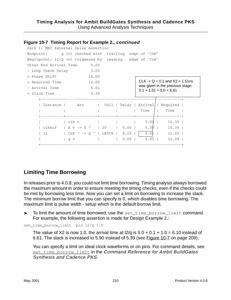
Timing Analysis for Ambit BuildGates Synthesis and Cadence PKSUsing Advanced Analysis Techniques
Figure 10-7 Timing Report for Example 2., continued
Limiting Time Borrowing
In releases prior to 4.0.8, you could not limit time borrowing. Timing analysis always borrowedthe maximum amount in order to ensure meeting the timing checks, even if the checks couldbe met by borrowing less time. Now you can set a limit on borrowing to increase the slack.The minimum borrow limit that you can specify is 0, which disables time borrowing. Themaximum limit is pulse width - setup which is the default borrow limit.
➤ To limit the amount of time borrowed, use the set_time_borrow_limit command.For example, the following assertion is made for Design Example 2.:
set_time_borrow_limit -pin l2/Q 1.0
The value of X2 is now 1.0, the arrival time at l2/q is 5.0 + 0.1 + 1.0 = 6.10 instead of6.61. The slack is increased to 5.90 instead of 5.39 (see Figure 10-7 on page 209).
You can specify a limit on ideal clock waveforms or on pins. For command details, seeset_time_borrow_limit in the Command Reference for Ambit BuildGatesSynthesis and Cadence PKS.
Path 1: MET External Delay Assertion
Endpoint: q (v) checked with trailing edge of ’CLK’
Beginpoint: i2/Q (v) triggered by leading edge of ’CLK’
Other End Arrival Time 5.00
- Loop Check Delay 3.00
+ Phase Shift 10.00
= Required Time 12.00
- Arrival Time 6.61
= Slack Time 5.39
+--------------------------------------------------------------+
| Instance | Arc | Cell | Delay | Arrival | Required |
| | | | | Time | Time |
|----------+--------------+-------+-------+---------+----------|
| | clk v | | | 5.00 | 10.39 |
| clkbuf | A v -> Z ^ | IV | 0.00 | 5.00 | 10.39 |
| i2 | CLK ^ -> Q ^ | LATCH | 0.10 | 6.61 | 12.00 |
| | q v | | 0.00 | 6.61 | 12.00 |
+--------------------------------------------------------------+
CLK -> Q = 0.1 and X2 = 1.51nswas given in the previous stage.0.1 + 1.51 + 5.0 = 6.61
May, 2001 210 Product Version 4.0.8
Timing Analysis for Ambit BuildGates Synthesis and Cadence PKSUsing Advanced Analysis Techniques
➤ To prevent time borrowing, set the limit to 0. This example disables time borrowing for thewhole design:
set_time_borrow_limit 0
You can also disable borrowing for specific waveforms or pins.
➤ To reset time borrowing to the default maximum value, use thereset_time_borrow_limit command as shown in this example:
reset_time_borrow_limit
The default is the maximum possible which is Max = pulse width - setup. The abovecommand resets the time borrowing to maximum possible for the whole design. You canalso reset specific waveforms or pins. For command details, seereset_time_borrow_limit in the Command Reference for Ambit BuildGatesSynthesis and Cadence PKS.
Getting Information about Time Borrow Limits
If you have previously set borrow limits, you can find out what they are.
➤ To display the time borrow limit as set by the set_time_borrow_limit command, usethe get_time_borrow_limit command. This example shows the value returned.
>get_time_borrow_limit -pin l2/Q
1.0
For command details, see get_time_borrow_limit in the Command Referencefor Ambit BuildGates Synthesis and Cadence PKS.
May, 2001 211 Product Version 4.0.8

Timing Analysis for Ambit BuildGates Synthesis and Cadence PKSUsing Advanced Analysis Techniques
On and Off Chip Variation Analysis
Simultaneous analysis lets you analyze two operating conditions at the same time. This savesiterations, but more importantly, lets you fix hold violations while the tool knows about theimpact on setup times.
Note: This functionality is available only if you are starting with a .alf (.lib ) or .tlfsource library.
There are two types of variation for which on and off chip variation analysis is desirable.
■ On-chip variation (min-max analysis)
The on-chip variation is the small difference in the operating parameter value across thechip. This is modeled in the library with linear k-factor derating tables. For simultaneousmin-max analysis, you can use either
❑ A single library containing both min and max values. For details, see “Min-maxAnalysis from a Single Library” on page 212.
❑ A merged library created from two libraries, one containing min data and the othermax data. For details, see “Min-max Analysis from Two Libraries” on page 213.
■ Off-chip variation (simultaneous BC-WC analysis)
The off-chip variation is a much larger range of values than on-chip and the derating isgenerally non-linear. This is modeled in the library as the PVT values. For this reason twooperating conditions are needed. For simultaneous best-worst analysis, you can useeither:
❑ A single library and two operating conditions. For details, see “BC-WC Analysis fromOne Library and Two Operating Conditions.” on page 214.
❑ Two libraries and two operating conditions. For details, see “BC-WC Analysis fromTwo Libraries and Two Operating Conditions” on page 214.
Analyzing Simultaneous Best Case and Worst Case On-Chip Variation
Min-max Analysis from a Single Library
Min/max delay numbers are obtained using on-chip PVT variations, specified as k-factors inthe library. Under this analysis, both early data and clock paths use min delay numbers andboth late data and clock paths use max delay numbers. You must specify process, voltageand temperature values for two different corners using set_operating_condition orset_operating_parameter commands. Here are the steps:
May, 2001 212 Product Version 4.0.8
Timing Analysis for Ambit BuildGates Synthesis and Cadence PKSUsing Advanced Analysis Techniques
1. Type this ac_shell command to set the analysis type to min_max
set_global timing_analysis_type min_max
2. Associate early paths with min and late paths with max by these commands
set_global pvt_early_path min
set_global pvt_late_path max
3. Associate one operating condition or parameter with min corner and another with max.For example
set_operating_condition -pvt min best
set_operating_condition -pvt max worst
The above associates the operating condition named best with the min corner and theoperating condition named worst with the max corner.
For complete syntax, see set_operating_condition andset_operating_parameter in the Command Reference for Ambit BuildGatesSynthesis and Cadence PKS.
Min-max Analysis from Two Libraries
In this case, you need to load both the min and max libraries using a single read_alf orread_tlf command. Under this analysis (as is the single library case), both late data andclock paths use max delay numbers and both early data and clock paths use min delaynumbers. Here are the steps:
1. Type this ac_shell command to set the analysis type to min_max
set_global timing_analysis_type min_max
2. Associate early paths with min and late paths with max by these commands
set_global pvt_early_path min
set_global pvt_late_path max
3. Read in the two libraries. For example
read_alf -min min_lib -max max_lib -name merged.alf
This merges the two libraries into one in the database and also writes the merged libraryto the file named merged.alf .
4. Associate one operating condition or parameter with min corner and another with max.For example
set_operating_condition -pvt min best
set_operating_condition -pvt max worst
May, 2001 213 Product Version 4.0.8
Timing Analysis for Ambit BuildGates Synthesis and Cadence PKSUsing Advanced Analysis Techniques
The above associates the operating condition named best with the min corner and theoperating condition named worst with the max corner.
Alternatively, you could use the read_library_update PVT options to set theenvironment corner as follows:
read_library_update -pvt min merged.alf
read_library_update -pvt max merged.alf
For complete syntax, see read_alf , read_tlf , set_operating_condition , andset_operating_parameter in the Command Reference for Ambit BuildGatesSynthesis and Cadence PKS.
Analyzing Simultaneous Best Case and Worst Case Off-Chip Variation
In this scenario, setup checks are performed at worst case PVT corner(s); and hold checksare performed at best case operating corner(s). In the simplest of the cases, you specify twoPVT corners (best and worst) and setup and hold checks are done as mentioned. There aretwo different ways of setting up BuildGates for simultaneous best case, worst case analyses:
BC-WC Analysis from One Library and Two Operating Conditions.
Here is an example of how this is setup in BuildGates
.Lib
set_operating_condition -pvt min best
set_operating_condition -pvt max worst
Common:
set_global pvt_early_path min
set_global pvt_late_path max
set_global timing_analysis_type bc_wc
In this case, setup checks are performed at worst case operating condition. The hold checksare performed at best case operating condition.
BC-WC Analysis from Two Libraries and Two Operating Conditions
Here is an example of how this is setup in BuildGates
.Lib
read_alf -min min_lib -max max_lib -name merged_library_name
set_operating_condition -library min_lib -pvt min best
May, 2001 214 Product Version 4.0.8
Timing Analysis for Ambit BuildGates Synthesis and Cadence PKSUsing Advanced Analysis Techniques
set_operating_condition -library max_lib -pvt max worst
Common:
set_global pvt_early_path min
set_global pvt_late_path max
set_global timing_analysis_type bc_wc
In this case, setup checks are performed at worst case operating condition. The worst casedelays are picked up from max_lib and appropriately scaled for operating condition worst.Similarly, the hold checks are performed at best case operating condition. The best casedelays are picked up from the min_lib library and scaled appropriately for best operatingcondition.
May, 2001 215 Product Version 4.0.8
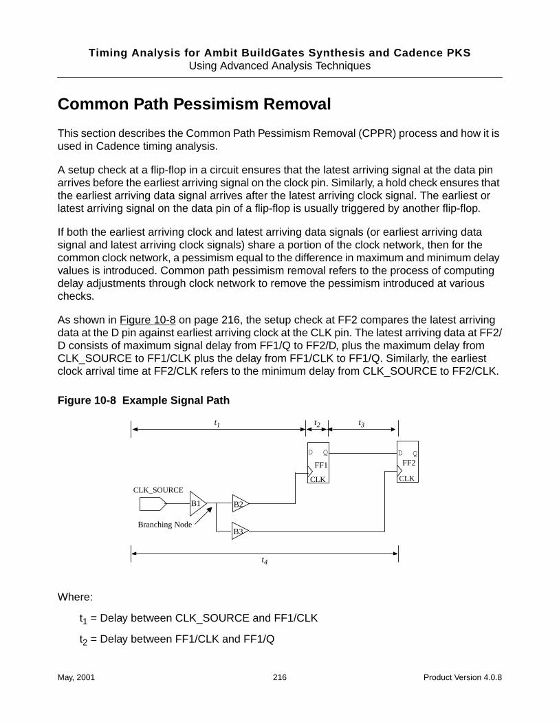
Timing Analysis for Ambit BuildGates Synthesis and Cadence PKSUsing Advanced Analysis Techniques
Common Path Pessimism Removal
This section describes the Common Path Pessimism Removal (CPPR) process and how it isused in Cadence timing analysis.
A setup check at a flip-flop in a circuit ensures that the latest arriving signal at the data pinarrives before the earliest arriving signal on the clock pin. Similarly, a hold check ensures thatthe earliest arriving data signal arrives after the latest arriving clock signal. The earliest orlatest arriving signal on the data pin of a flip-flop is usually triggered by another flip-flop.
If both the earliest arriving clock and latest arriving data signals (or earliest arriving datasignal and latest arriving clock signals) share a portion of the clock network, then for thecommon clock network, a pessimism equal to the difference in maximum and minimum delayvalues is introduced. Common path pessimism removal refers to the process of computingdelay adjustments through clock network to remove the pessimism introduced at variouschecks.
As shown in Figure 10-8 on page 216, the setup check at FF2 compares the latest arrivingdata at the D pin against earliest arriving clock at the CLK pin. The latest arriving data at FF2/D consists of maximum signal delay from FF1/Q to FF2/D, plus the maximum delay fromCLK_SOURCE to FF1/CLK plus the delay from FF1/CLK to FF1/Q. Similarly, the earliestclock arrival time at FF2/CLK refers to the minimum delay from CLK_SOURCE to FF2/CLK.
Figure 10-8 Example Signal Path
Where:
t1 = Delay between CLK_SOURCE and FF1/CLK
t2 = Delay between FF1/CLK and FF1/Q
FF1 FF2
B1 B2
B3
CLK_SOURCE
Branching Node
DQ
t1 t3t2
t4
CLKCLK
D Q
May, 2001 216 Product Version 4.0.8
Timing Analysis for Ambit BuildGates Synthesis and Cadence PKSUsing Advanced Analysis Techniques
t3 = Delay between FF1/Q and FF2/D
t4 = Delay between CLK_SOURCE and FF2/CLK
The resulting setup check equation without removal of pessimism is as follows:
t1max + t2max + t3max + tsu <= t4min + tpa
Where:
tpa = Period adjustment
tsu = Setup time
In the above equation, it is assumed that the common clock network simultaneously exhibitsmaximum delay for the data path (clock source to FF1/CLK) and minimum delay for the clockpath (clock source to FF2/CLK), which is impossible. Common path pessimism removal(CPPR) refer to the process of removing this pessimism. If common path pessimism time(t cpp ) is defined as the difference in the maximum and minimum delay from the clock sourceto the branching node, the actual setup check equation is as follows:
t1max + t2max +t3max +tsu <= t4min + tpa+ tcpp
Similarly, the hold check equation is as follows.
t1min + t2min + t3min + tcpp >= t4max + tH
Where:
tH = Hold time
Common Path Pessimism Removal Command
The command for computing common path pessimism adjustment is explained below. Forsyntax details, see do_cppr_analysis in the Command Reference for AmbitBuildGates Synthesis and Cadence PKS.
do_cppr_analysis -slack_limit slack_limit [-critical]
[-late | -early]
Common path pessimism removal is an expensive operation. The switch -slack_limitremoves clock pessimism only from paths whose slack is worse than the specified slack limit.
Pessimism removal can be specified for either early or late data paths. By default, thecommand will remove pessimism from both the early and the late data paths.
May, 2001 217 Product Version 4.0.8
Timing Analysis for Ambit BuildGates Synthesis and Cadence PKSUsing Advanced Analysis Techniques
As common path pessimism is removed from a path, some other path for which common pathpessimism has not been removed may become critical. The CPPR algorithm visits each endpoint and repeatedly removes path pessimism from the most critical path to the end point, forwhich common path pessimism has not been removed and while its slack is still worse thanthe slack limit specified.
For each end point, when the critical option is specified, the common path pessimism removalprocess stops when the most critical path to the end point already has its common pathpessimism removed. By default, the common path pessimism removal process continuesuntil the pessimisms are removed for all paths to the end point whose slacks are worse thanslack_limit .
Note: CPPR analysis must be rerun when either a change to the netlist or timing data hasbeen made.
Subsequent to executing the do_cppr_analysis command, all future slack queries (suchas report_timing) will take into account CPPR adjustments. Similarly, any changes to thenetlist due to timing optimization will take into account CPPR adjustments. For any structuralchanges to the clock network of the netlist (on which synthesis does NOT work) or changesto the data network or timing assertions (because of slack dependence introduced by theslack_limit option), CPPR adjustments will have to be recomputed. Since CPPR analysisis an expensive operation, recomputation of adjustments is not performed automatically everytime the netlist or the timing assertions change. The do_cppr_analysis command mustbe explicitly invoked. The do_cppr_analysis command deletes previously computedadjustments and recomputes.
Note: CPPR data is not currently saved when writing the database out to an .adb file. If an.adb database is restored, the CPPR analysis must be rerun.
CPPR Script Example
The following script shows CPPR being run in the context of timing analysis:
# Read timing libraries
set TargetTech [read_alf stdcell_wccom.alf]
set_global target_technology $TargetTech
set_operating_condition WORST_CASE
# load design
read_verilog chip.v
do_build_generic
set_top_timing_module chip
set_current_module chip
# Set up timing constraints on the design
source TimingConstraints.tcl
May, 2001 218 Product Version 4.0.8
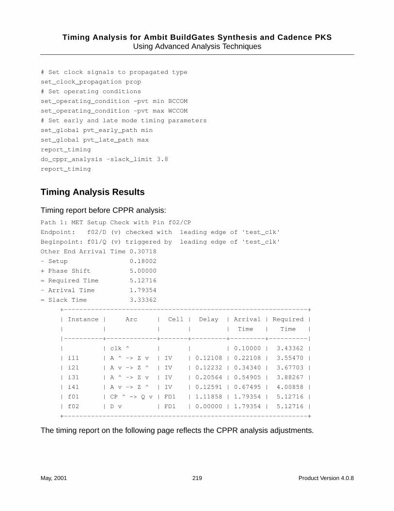
Timing Analysis for Ambit BuildGates Synthesis and Cadence PKSUsing Advanced Analysis Techniques
# Set clock signals to propagated type
set_clock_propagation prop
# Set operating conditions
set_operating_condition -pvt min BCCOM
set_operating_condition -pvt max WCCOM
# Set early and late mode timing parameters
set_global pvt_early_path min
set_global pvt_late_path max
report_timing
do_cppr_analysis -slack_limit 3.8
report_timing
Timing Analysis Results
Timing report before CPPR analysis:
Path 1: MET Setup Check with Pin f02/CP
Endpoint: f02/D (v) checked with leading edge of 'test_clk'
Beginpoint: f01/Q (v) triggered by leading edge of 'test_clk'
Other End Arrival Time 0.30718
- Setup 0.18002
+ Phase Shift 5.00000
= Required Time 5.12716
- Arrival Time 1.79354
= Slack Time 3.33362
+---------------------------------------------------------------+
| Instance | Arc | Cell | Delay | Arrival | Required |
| | | | | Time | Time |
|----------+-------------+-------+---------+---------+----------|
| | clk ^ | | | 0.10000 | 3.43362 |
| i11 | A ^ -> Z v | IV | 0.12108 | 0.22108 | 3.55470 |
| i21 | A v -> Z ^ | IV | 0.12232 | 0.34340 | 3.67703 |
| i31 | A ^ -> Z v | IV | 0.20564 | 0.54905 | 3.88267 |
| i41 | A v -> Z ^ | IV | 0.12591 | 0.67495 | 4.00858 |
| f01 | CP ^ -> Q v | FD1 | 1.11858 | 1.79354 | 5.12716 |
| f02 | D v | FD1 | 0.00000 | 1.79354 | 5.12716 |
+---------------------------------------------------------------+
The timing report on the following page reflects the CPPR analysis adjustments.
May, 2001 219 Product Version 4.0.8
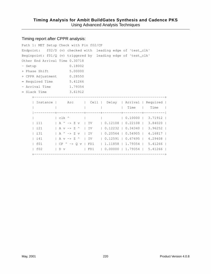
Timing Analysis for Ambit BuildGates Synthesis and Cadence PKSUsing Advanced Analysis Techniques
Timing report after CPPR analysis:
Path 1: MET Setup Check with Pin f02/CP
Endpoint: f02/D (v) checked with leading edge of 'test_clk'
Beginpoint: f01/Q (v) triggered by leading edge of 'test_clk'
Other End Arrival Time 0.30718
- Setup 0.18002
+ Phase Shift 5.00000
+ CPPR Adjustment 0.28550
= Required Time 5.41266
- Arrival Time 1.79354
= Slack Time 3.61912
+---------------------------------------------------------------+
| Instance | Arc | Cell | Delay | Arrival | Required |
| | | | | Time | Time |
|----------+-------------+-------+---------+---------+----------|
| | clk ^ | | | 0.10000 | 3.71912 |
| i11 | A ^ -> Z v | IV | 0.12108 | 0.22108 | 3.84020 |
| i21 | A v -> Z ^ | IV | 0.12232 | 0.34340 | 3.96252 |
| i31 | A ^ -> Z v | IV | 0.20564 | 0.54905 | 4.16817 |
| i41 | A v -> Z ^ | IV | 0.12591 | 0.67495 | 4.29408 |
| f01 | CP ^ -> Q v | FD1 | 1.11858 | 1.79354 | 5.41266 |
| f02 | D v | FD1 | 0.00000 | 1.79354 | 5.41266 |
+---------------------------------------------------------------+
May, 2001 220 Product Version 4.0.8
Timing Analysis for Ambit BuildGates Synthesis and Cadence PKS
ASample Tcl Scripts
This appendix provides sample Tcl scripts for use in the Ambit® BuildGates® synthesisac_shell environment. Its focus is on synthesis of a single module.
All relevant commands are described in detail in the Command Reference for AmbitBuildGates Synthesis and Cadence PKS. See the Ambit BuildGates Synthesis UserGuide for information on using ac_shell . Online help is available through the command lineinterface in ac_shell by typing help command_name at the prompt.
This chapter contains the following information:
■ Converting Synopsys Scripts on page 222
■ Modular Scripts on page 222
■ Setting up the Synthesis Environment on page 223
■ Reading Files on page 224
■ Clocking and Default Constraints on page 224
■ Applying Time Budget Constraints on page 225
■ Design Rule Constraints on page 226
■ Optimization on page 227
■ Writing Files on page 228
■ Writing Reports on page 228
May, 2001 221 Product Version 4.0.8
Timing Analysis for Ambit BuildGates Synthesis and Cadence PKSSample Tcl Scripts
Converting Synopsys Scripts
The methodology differences are outlined in this document. For the complete mapping ofdc_shell and pt_shell to ac_shell commands, see “Translating Constraints” in theConstraint Translator for Ambit BuildGates Synthesis and Cadence PKS.
Modular Scripts
The Tcl interface allows you to keep your scripts modular and reusable. Sections of code thatare common between blocks can be written as procedures, with arguments to handleexception cases.
The following is a sample script showing the synthesis of a given module. The routinesbeginning with the arbitrary prefix “my_” are defined in the following pages.
proc my_block { top ver_files adb_files clk } {
my_setup
my_read_lib
if { $adb_files != ““ } {
# read sub-blocks previously synthesized
my_read_adb $adb_files
}
my_read_verilog $top $ver_files
# set default and then detailed constraints
my_set_default_constraints $clk
source $top.con
my_optimize
my_write_files $top
my_report $top
}
This could be called from another script or from an interactive session:
my_block dma_ctl { reg4.v dma_ctl.v } { reg1.adb } clk4
May, 2001 222 Product Version 4.0.8
Timing Analysis for Ambit BuildGates Synthesis and Cadence PKSSample Tcl Scripts
Setting up the Synthesis Environment
Most global variables that affect an entire synthesis session are grouped into theset_global and get_global command pair. Typing help set_global will return acomplete listing of these variables.
Search paths are specified differently in ac_shell than in dc_shell . For information onuse of multiple target libraries, refer to Chapter 2, “Choosing a Methodology.”
proc my_setup {
# Here are some common global settings.
# show all commands as they are executed
set_global echo_commands true
# max_fanout
set_global fanout_load_limit 12
# search path for read_verilog
set_global vpp_arg “-I. -I/design/rtl”
# Any other number of global settings, for example
# to turn off the warnings about delays not supported:
set_message_verbosity VLOG-035 off
}
A typical procedure to read the library is shown below. Note that the wire load mode can beset here. The wire load model (not mode) must be set after reading in a design because it isattached to the current module.
proc my_read_lib {
read_alf /path/to/lib.alf
set_global target_technology libname
set_wire_load_mode top
set_operating_condition WCCOM
}
May, 2001 223 Product Version 4.0.8
Timing Analysis for Ambit BuildGates Synthesis and Cadence PKSSample Tcl Scripts
Reading Files
The read_verilog command builds a control-data-flow-graph (CDFG), but does notpopulate any netlist. The do_build_generic command creates a generic (AND-OR-NOT)netlist from the CDFG (see example below).
A Script Showing How to Read Verilog Files
The following script shows how to read Verilog files.
proc my_read_verilog { top ver_files } {
read_verilog $ver_files
do_build_generic
set_current_module $top
set_top_timing_module $top
}
Clocking and Default Constraints
ac_shell supports a complete clocking environment that includes multiple clocks, clockskews, and clock uncertainty. The dc_shell is different in that an ideal clock must first bedefined, then separately attached to (each) clock port. The name for this ideal clock isarbitrary and may have the same name as the clock port, if this helps to simplify the scriptconversion.
It may appear that the ideal clock definition (set_clock ) and the set_clock_root andset_clock_insertion_delay assertions contain redundant information, but there arecases when all of these degrees of freedom can be used. The ideal clock waveform directsthe timing analyzer in determining phase shifts; that is, the clock period when a signal mustbe valid. The insertion delays (arrival rise and fall times) specify the skew on the particularclock port.
Note that the order of applying clock arrival time and data arrival time to a given port isimportant. Whichever occurs first determines whether the port becomes a clock or data port,respectively. In the script below, the -no_clocks flag is used with the find command toprevent such a situation.
Applying your own default constraints is not required if you are going to apply specificconstraints to each port, but it is a safeguard against any omission. Otherwise, ac_shelldefaults are the same as dc_shell defaults of infinite drive strength on input ports, zerocapacitance on output ports, and no arrival or required times (no timing checks performed).
proc my_set_default_constraints { clk } {
May, 2001 224 Product Version 4.0.8
Timing Analysis for Ambit BuildGates Synthesis and Cadence PKSSample Tcl Scripts
# $clk is the name of the clock port. CLOCK is the name of the ideal #clock.
set_clock CLOCK -waveform {0 4} -period 8
set_clock_root -clock CLOCK $clk
set_clock_insertion_delay -clock CLOCK -rise 0 -pin $clk
set_clock_insertion_delay -clock CLOCK -fall 4 -pin $clk
set_dont_modify -network [find -port $clk]
set_clock_uncertainty -early 0.5 -clock_to CLOCK
set_clock_uncertainty -late 0.5 -clock_to CLOCK
# Insert your own drive cell and capacitance here
set_drive_cell -cell IV [find -port -input -no_clocks .]
set_port_capacitance [get_cell_pin_load -cell IV \
-pin A] [find -port -output .]
# Alternate form:
set_drive_resistance 0.8 [find -port -input -no_clocks .]
set_input_delay -clock CLOCK 0 [find -port -input -no_clocks .]
set_data_required_time 5.0 -clock CLOCK [find -port -output \
-no_clocks .]
# Alternate form (for set_output_delay/set_data_required_time)
# This method uses relative time:
set_external_delay 3.0 -clock CLOCK \
[find -port -output -no_clocks .]
}
Applying Time Budget Constraints
Detailed constraints files (also called time budgets) consist of arrival times, required times,drive strength, and port capacitance for each port of the top level module being optimized ina single synthesis run. It is helpful to separate this bulk data from the rest of the control-flowscripts. There may also be multi-cycle and false path information.
The dc_shell commands set_input_delay and set_output_delay translate easily tothe ac_shell commands set_input_delay and set_external_delay .
For combinational circuits, dc_shell command set_max_delay translates toset_path_delay_constraint .
May, 2001 225 Product Version 4.0.8
Timing Analysis for Ambit BuildGates Synthesis and Cadence PKSSample Tcl Scripts
Tip
Overconstraining designs in general does not lead to better performance withac_shell , especially if you are accustomed to 10% to 20% overconstraining.Realistic constraints usually perform better with ac_shell when overconstrainedby 0% to 5%.
Multi-cycle and false paths are supported by the ac_shell commandsset_cycle_addition and set_false_path , respectively. Note that a 2-cycle path indc_shell becomes a 1 cycle-addition in ac_shell .
The advantage of this command is apparent when applying intersecting multi-cycleconstraints. The cycle-number may be negative in complex cases.
set_cycle_addition 1.0 -from “read_addr”
set_cycle_addition -false -to “data_reg/D”
The command check_timing is available to report on any inconsistencies found in theconstraint environment.
Design Rule Constraints
In addition to constraints, which guide the synthesis process, Ambit BuildGates synthesissupports the notion of design rule constraints. These are conditions that must be met for theresulting circuit to be acceptable, and therefore take priority over meeting optimizationconstraints.
max_transition
The max_transition command is set globally in the .lib library format withdefault_max_transition . Related dc_shell commands are:
set_max_transition 0.5 <top_module>
set_max_transition 0.5 <ports>
In ac_shell it is possible to override the default for the complete design, or to set the limitfor a particular port with one of the following. Currently, ac_shell does not support settingthe limit on a particular module.
set_global slew_time_limit 0.5
set_slew_time_limit 0.5 <ports>
Note: slew_limit has been renamed to slew_time_limit .
May, 2001 226 Product Version 4.0.8
Timing Analysis for Ambit BuildGates Synthesis and Cadence PKSSample Tcl Scripts
max_capacitance
The max_capacitance command is set globally in the .lib library format withdefault_max_capacitance . Related dc_shell commands are:
set_max_capacitance 0.5 <top_module>
set_max_capacitance 0.5 <ports>
In ac_shell it is possible to override the default for the complete design, or to set the limitfor a particular port with one of the following. Currently, ac_shell does not support settingthe limit on a particular module.
set_global capacitance_limit 0.5
set_port_capacitance_limit 0.5 <ports>
Note: capacitance_limit has been renamed to port_capacitance_limit .
The dc_shell command set_load translates directly to ac_shellset_port_capacitance .
max_fanout
The max_fanout command is set globally in the .lib library format withdefault_max_fanout . Related dc_shell commands are:
set_max_fanout 0.5 <top_module>
set_max_fanout 0.5 <ports>
In ac_shell it is possible to override the default for the complete design, or to set the limit fora particular port with one of the following. Currently, ac_shell does not support setting thelimit on a particular module.
set_global fanout_load_limit 0.5
set_fanout_load_limit 0.5 <ports>
The dc_shell command set_fanout_load translates directly to the ac_shellset_fanout_load .
Optimization
The following is a simple optimization procedure:
proc my_optimize {} {
do_optimize -effort high
do_xform_fix_multiport_nets -fix_constant_ports
}
May, 2001 227 Product Version 4.0.8
Timing Analysis for Ambit BuildGates Synthesis and Cadence PKSSample Tcl Scripts
Use the following commands on the ac_shell command line to view more optimizationoptions:
ac_shell> help do_optimize
ac_shell> help do_timing_correction
ac_shell> help xform
In particular, the critical ratio or critical offset options with values higher than the default (0)can be useful if the constraints are reasonable.
Writing Files
The following is a sample procedure that allows you to write to files. Using the flag -hierallows you to write out the entire hierarchy. The Verilog writer has several flags. Type helpset_global for more details.
proc my_write_files { top } {
mkdir -p netlist adb
write_verilog -hier netlist/$top.vm
write_adb -hier adb/$top.adb
}
Writing Reports
A variety of reports are available.
Note: The output redirection characters, > and >>, are supported.
In addition, each report command takes an output file as an argument:
proc my_report { top } {
mkdir -p report
report_timing -max_points 10 report/$top.timing
report_area report/$top.area
report_area -block report/$top.block
report_hierarchy report/$top.hier
}
May, 2001 228 Product Version 4.0.8
Timing Analysis for Ambit BuildGates Synthesis and Cadence PKS
BGenerating GCF Files
This appendix contains information about the General Constraint Format (GCF) file that canbe created from Cadence® timing analysis.
■ Generating GCF 1.4 on page 230
■ Example on page 236
May, 2001 229 Product Version 4.0.8
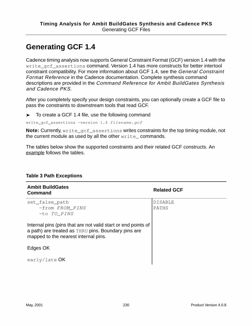
Timing Analysis for Ambit BuildGates Synthesis and Cadence PKSGenerating GCF Files
Generating GCF 1.4
Cadence timing analysis now supports General Constraint Format (GCF) version 1.4 with thewrite_gcf_assertions command. Version 1.4 has more constructs for better intertoolconstraint compatibility. For more information about GCF 1.4, see the General ConstraintFormat Reference in the Cadence documentation. Complete synthesis commanddescriptions are provided in the Command Reference for Ambit BuildGates Synthesisand Cadence PKS.
After you completely specify your design constraints, you can optionally create a GCF file topass the constraints to downstream tools that read GCF.
➤ To create a GCF 1.4 file, use the following command
write_gcf_assertions -version 1.4 filename.gcf
Note: Currently, write_gcf_assertions writes constraints for the top timing module, notthe current module as used by all the other write_ commands.
The tables below show the supported constraints and their related GCF constructs. Anexample follows the tables.
Table 3 Path Exceptions
Ambit BuildGatesCommand Related GCF
set_false_path-from FROM_PINS-to TO_PINS
Internal pins (pins that are not valid start or end points ofa path) are treated as THRU pins. Boundary pins aremapped to the nearest internal pins.
Edges OK
early/late OK
DISABLEPATHS
May, 2001 230 Product Version 4.0.8
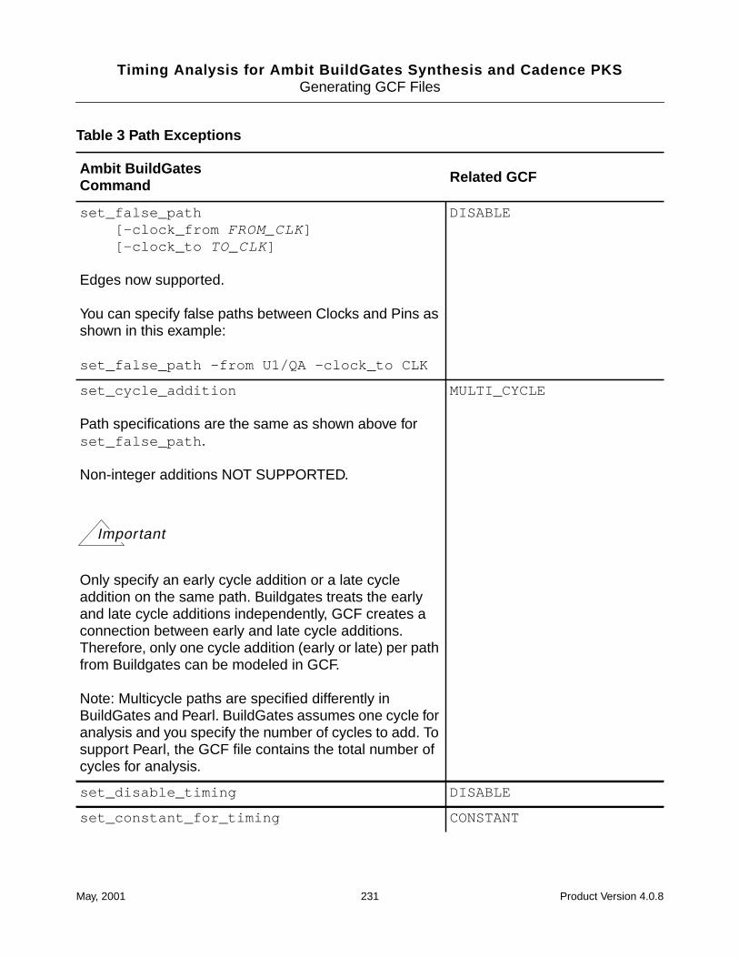
Timing Analysis for Ambit BuildGates Synthesis and Cadence PKSGenerating GCF Files
set_false_path[-clock_from FROM_CLK][-clock_to TO_CLK]
Edges now supported.
You can specify false paths between Clocks and Pins asshown in this example:
set_false_path -from U1/QA -clock_to CLK
DISABLE
set_cycle_addition
Path specifications are the same as shown above forset_false_path .
Non-integer additions NOT SUPPORTED.
Only specify an early cycle addition or a late cycleaddition on the same path. Buildgates treats the earlyand late cycle additions independently, GCF creates aconnection between early and late cycle additions.Therefore, only one cycle addition (early or late) per pathfrom Buildgates can be modeled in GCF.
Note: Multicycle paths are specified differently inBuildGates and Pearl. BuildGates assumes one cycle foranalysis and you specify the number of cycles to add. Tosupport Pearl, the GCF file contains the total number ofcycles for analysis.
MULTI_CYCLE
set_disable_timing DISABLE
set_constant_for_timing CONSTANT
Table 3 Path Exceptions
Ambit BuildGatesCommand Related GCF
Important
May, 2001 231 Product Version 4.0.8
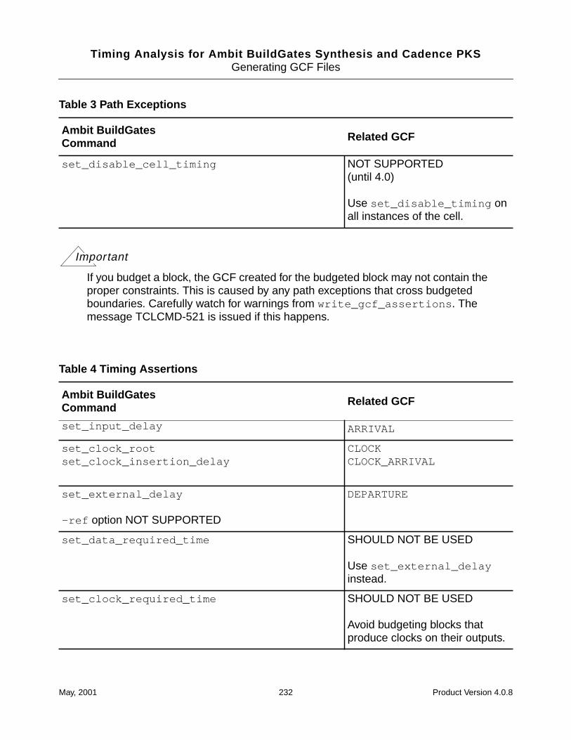
Timing Analysis for Ambit BuildGates Synthesis and Cadence PKSGenerating GCF Files
Important
If you budget a block, the GCF created for the budgeted block may not contain theproper constraints. This is caused by any path exceptions that cross budgetedboundaries. Carefully watch for warnings from write_gcf_assertions . Themessage TCLCMD-521 is issued if this happens.
set_disable_cell_timing NOT SUPPORTED(until 4.0)
Use set_disable_timing onall instances of the cell.
Table 4 Timing Assertions
Ambit BuildGatesCommand Related GCF
set_input_delay ARRIVAL
set_clock_rootset_clock_insertion_delay
CLOCKCLOCK_ARRIVAL
set_external_delay
-ref option NOT SUPPORTED
DEPARTURE
set_data_required_time SHOULD NOT BE USED
Use set_external_delayinstead.
set_clock_required_time SHOULD NOT BE USED
Avoid budgeting blocks thatproduce clocks on their outputs.
Table 3 Path Exceptions
Ambit BuildGatesCommand Related GCF
May, 2001 232 Product Version 4.0.8
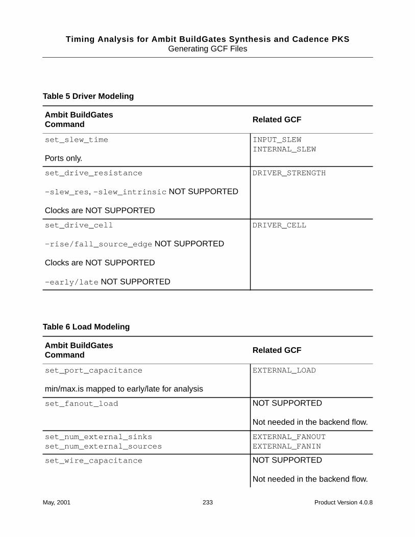
Timing Analysis for Ambit BuildGates Synthesis and Cadence PKSGenerating GCF Files
Table 5 Driver Modeling
Ambit BuildGatesCommand Related GCF
set_slew_time
Ports only.
INPUT_SLEWINTERNAL_SLEW
set_drive_resistance
-slew_res , -slew_intrinsic NOT SUPPORTED
Clocks are NOT SUPPORTED
DRIVER_STRENGTH
set_drive_cell
-rise/fall_source_edge NOT SUPPORTED
Clocks are NOT SUPPORTED
-early/late NOT SUPPORTED
DRIVER_CELL
Table 6 Load Modeling
Ambit BuildGatesCommand Related GCF
set_port_capacitance
min/max.is mapped to early/late for analysis
EXTERNAL_LOAD
set_fanout_load NOT SUPPORTED
Not needed in the backend flow.
set_num_external_sinksset_num_external_sources
EXTERNAL_FANOUTEXTERNAL_FANIN
set_wire_capacitance NOT SUPPORTED
Not needed in the backend flow.
May, 2001 233 Product Version 4.0.8
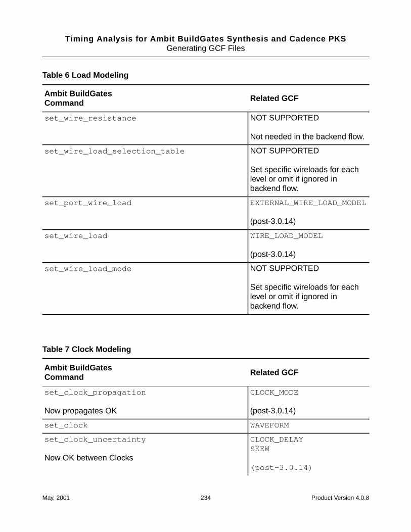
Timing Analysis for Ambit BuildGates Synthesis and Cadence PKSGenerating GCF Files
set_wire_resistance NOT SUPPORTED
Not needed in the backend flow.
set_wire_load_selection_table NOT SUPPORTED
Set specific wireloads for eachlevel or omit if ignored inbackend flow.
set_port_wire_load EXTERNAL_WIRE_LOAD_MODEL
(post-3.0.14)
set_wire_load WIRE_LOAD_MODEL
(post-3.0.14)
set_wire_load_mode NOT SUPPORTED
Set specific wireloads for eachlevel or omit if ignored inbackend flow.
Table 7 Clock Modeling
Ambit BuildGatesCommand Related GCF
set_clock_propagation
Now propagates OK
CLOCK_MODE
(post-3.0.14)
set_clock WAVEFORM
set_clock_uncertainty
Now OK between Clocks
CLOCK_DELAYSKEW
(post-3.0.14)
Table 6 Load Modeling
Ambit BuildGatesCommand Related GCF
May, 2001 234 Product Version 4.0.8
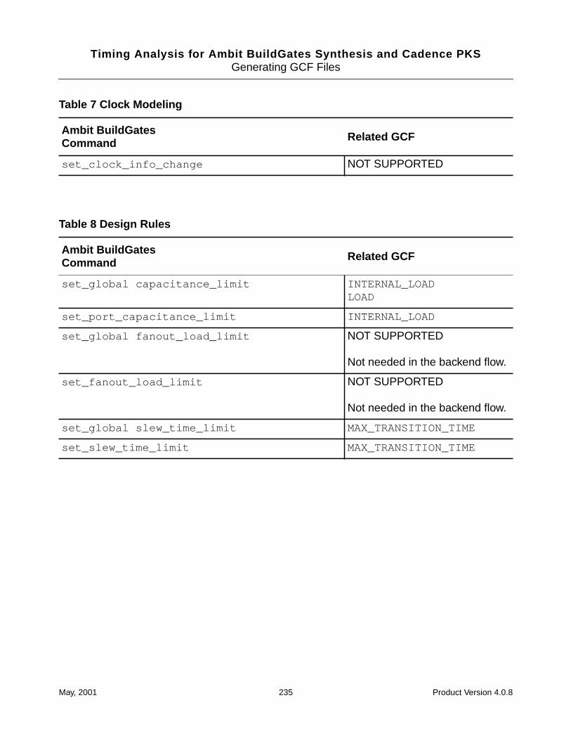
Timing Analysis for Ambit BuildGates Synthesis and Cadence PKSGenerating GCF Files
set_clock_info_change NOT SUPPORTED
Table 8 Design Rules
Ambit BuildGatesCommand Related GCF
set_global capacitance_limit INTERNAL_LOADLOAD
set_port_capacitance_limit INTERNAL_LOAD
set_global fanout_load_limit NOT SUPPORTED
Not needed in the backend flow.
set_fanout_load_limit NOT SUPPORTED
Not needed in the backend flow.
set_global slew_time_limit MAX_TRANSITION_TIME
set_slew_time_limit MAX_TRANSITION_TIME
Table 7 Clock Modeling
Ambit BuildGatesCommand Related GCF
May, 2001 235 Product Version 4.0.8
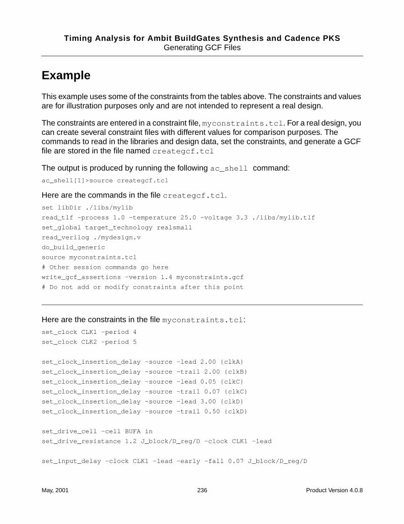
Timing Analysis for Ambit BuildGates Synthesis and Cadence PKSGenerating GCF Files
Example
This example uses some of the constraints from the tables above. The constraints and valuesare for illustration purposes only and are not intended to represent a real design.
The constraints are entered in a constraint file, myconstraints.tcl . For a real design, youcan create several constraint files with different values for comparison purposes. Thecommands to read in the libraries and design data, set the constraints, and generate a GCFfile are stored in the file named creategcf.tcl
The output is produced by running the following ac_shell command:
ac_shell[1]>source creategcf.tcl
Here are the commands in the file creategcf.tcl .
set libDir ./libs/mylib
read_tlf -process 1.0 -temperature 25.0 -voltage 3.3 ./libs/mylib.tlf
set_global target_technology realsmall
read_verilog ./mydesign.v
do_build_generic
source myconstraints.tcl
# Other session commands go here
write_gcf_assertions -version 1.4 myconstraints.gcf
# Do not add or modify constraints after this point
Here are the constraints in the file myconstraints.tcl :
set_clock CLK1 -period 4
set_clock CLK2 -period 5
set_clock_insertion_delay -source -lead 2.00 {clkA}
set_clock_insertion_delay -source -trail 2.00 {clkB}
set_clock_insertion_delay -source -lead 0.05 {clkC}
set_clock_insertion_delay -source -trail 0.07 {clkC}
set_clock_insertion_delay -source -lead 3.00 {clkD}
set_clock_insertion_delay -source -trail 0.50 {clkD}
set_drive_cell -cell BUFA in
set_drive_resistance 1.2 J_block/D_reg/D -clock CLK1 -lead
set_input_delay -clock CLK1 -lead -early -fall 0.07 J_block/D_reg/D
May, 2001 236 Product Version 4.0.8
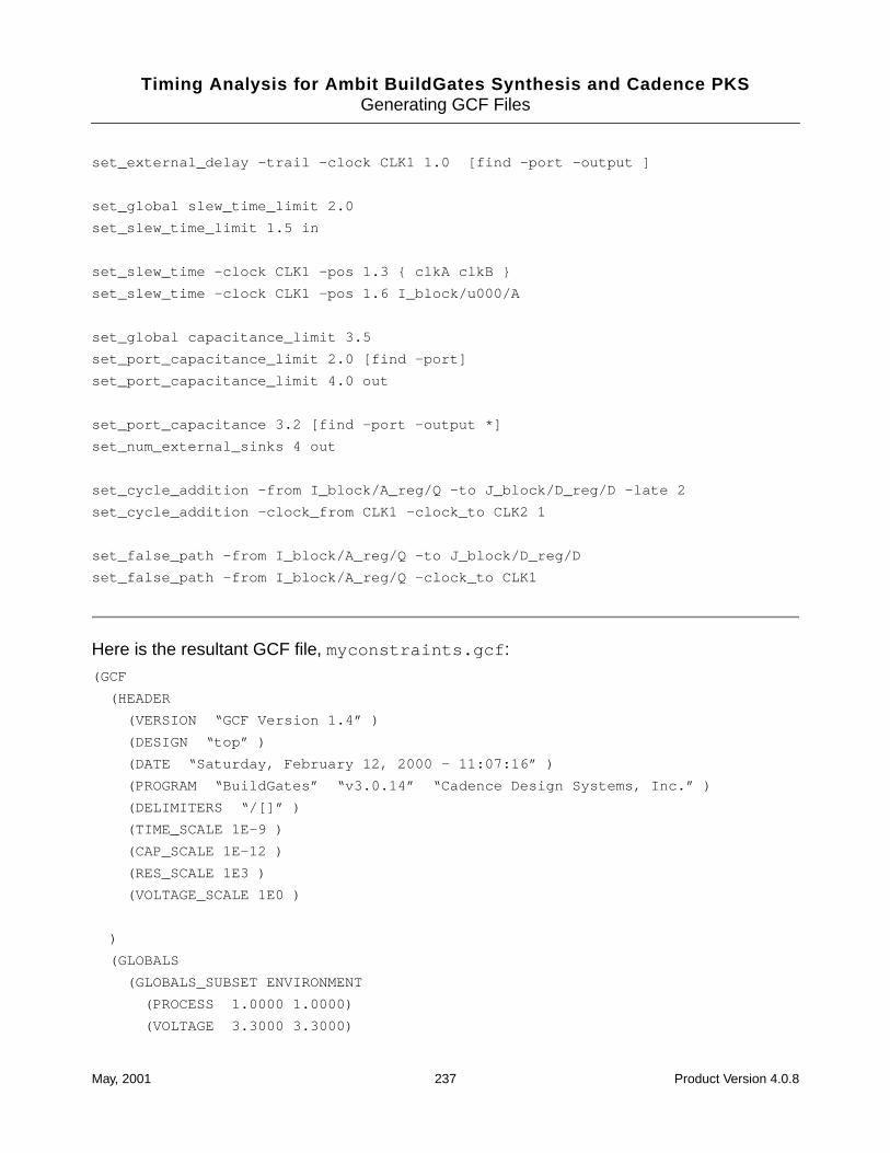
Timing Analysis for Ambit BuildGates Synthesis and Cadence PKSGenerating GCF Files
set_external_delay -trail -clock CLK1 1.0 [find -port -output ]
set_global slew_time_limit 2.0
set_slew_time_limit 1.5 in
set_slew_time -clock CLK1 -pos 1.3 { clkA clkB }
set_slew_time -clock CLK1 -pos 1.6 I_block/u000/A
set_global capacitance_limit 3.5
set_port_capacitance_limit 2.0 [find -port]
set_port_capacitance_limit 4.0 out
set_port_capacitance 3.2 [find -port -output *]
set_num_external_sinks 4 out
set_cycle_addition -from I_block/A_reg/Q -to J_block/D_reg/D -late 2
set_cycle_addition -clock_from CLK1 -clock_to CLK2 1
set_false_path -from I_block/A_reg/Q -to J_block/D_reg/D
set_false_path -from I_block/A_reg/Q -clock_to CLK1
Here is the resultant GCF file, myconstraints.gcf :
(GCF
(HEADER
(VERSION “GCF Version 1.4” )
(DESIGN “top” )
(DATE “Saturday, February 12, 2000 - 11:07:16” )
(PROGRAM “BuildGates” “v3.0.14” “Cadence Design Systems, Inc.” )
(DELIMITERS “/[]” )
(TIME_SCALE 1E-9 )
(CAP_SCALE 1E-12 )
(RES_SCALE 1E3 )
(VOLTAGE_SCALE 1E0 )
)
(GLOBALS
(GLOBALS_SUBSET ENVIRONMENT
(PROCESS 1.0000 1.0000)
(VOLTAGE 3.3000 3.3000)
May, 2001 237 Product Version 4.0.8
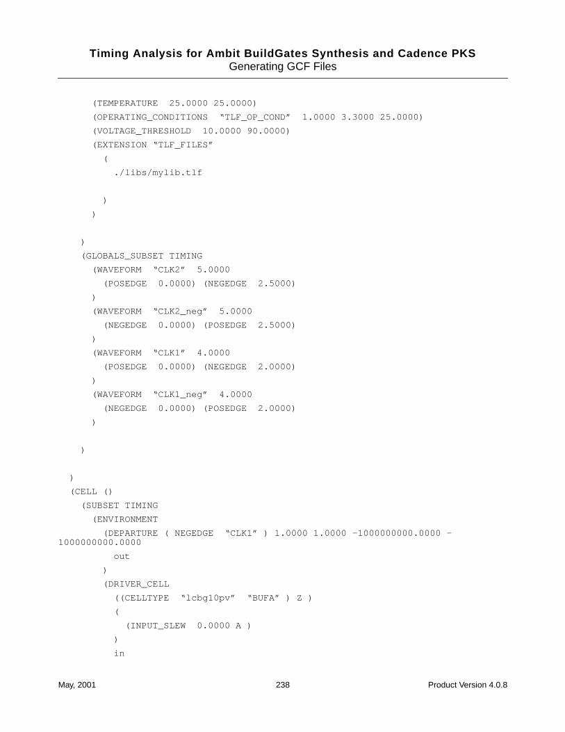
Timing Analysis for Ambit BuildGates Synthesis and Cadence PKSGenerating GCF Files
(TEMPERATURE 25.0000 25.0000)
(OPERATING_CONDITIONS “TLF_OP_COND” 1.0000 3.3000 25.0000)
(VOLTAGE_THRESHOLD 10.0000 90.0000)
(EXTENSION “TLF_FILES”
(
./libs/mylib.tlf
)
)
)
(GLOBALS_SUBSET TIMING
(WAVEFORM “CLK2” 5.0000
(POSEDGE 0.0000) (NEGEDGE 2.5000)
)
(WAVEFORM “CLK2_neg” 5.0000
(NEGEDGE 0.0000) (POSEDGE 2.5000)
)
(WAVEFORM “CLK1” 4.0000
(POSEDGE 0.0000) (NEGEDGE 2.0000)
)
(WAVEFORM “CLK1_neg” 4.0000
(NEGEDGE 0.0000) (POSEDGE 2.0000)
)
)
)
(CELL ()
(SUBSET TIMING
(ENVIRONMENT
(DEPARTURE ( NEGEDGE “CLK1” ) 1.0000 1.0000 -1000000000.0000 -1000000000.0000
out
)
(DRIVER_CELL
((CELLTYPE “lcbg10pv” “BUFA” ) Z )
(
(INPUT_SLEW 0.0000 A )
)
in
May, 2001 238 Product Version 4.0.8
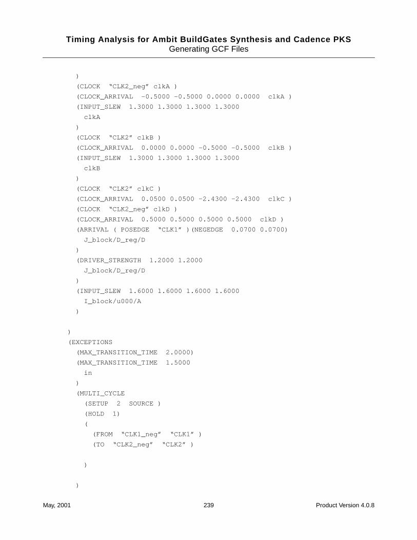
Timing Analysis for Ambit BuildGates Synthesis and Cadence PKSGenerating GCF Files
)
(CLOCK “CLK2_neg” clkA )
(CLOCK_ARRIVAL -0.5000 -0.5000 0.0000 0.0000 clkA )
(INPUT_SLEW 1.3000 1.3000 1.3000 1.3000
clkA
)
(CLOCK “CLK2” clkB )
(CLOCK_ARRIVAL 0.0000 0.0000 -0.5000 -0.5000 clkB )
(INPUT_SLEW 1.3000 1.3000 1.3000 1.3000
clkB
)
(CLOCK “CLK2” clkC )
(CLOCK_ARRIVAL 0.0500 0.0500 -2.4300 -2.4300 clkC )
(CLOCK “CLK2_neg” clkD )
(CLOCK_ARRIVAL 0.5000 0.5000 0.5000 0.5000 clkD )
(ARRIVAL ( POSEDGE “CLK1” )(NEGEDGE 0.0700 0.0700)
J_block/D_reg/D
)
(DRIVER_STRENGTH 1.2000 1.2000
J_block/D_reg/D
)
(INPUT_SLEW 1.6000 1.6000 1.6000 1.6000
I_block/u000/A
)
)
(EXCEPTIONS
(MAX_TRANSITION_TIME 2.0000)
(MAX_TRANSITION_TIME 1.5000
in
)
(MULTI_CYCLE
(SETUP 2 SOURCE )
(HOLD 1)
(
(FROM “CLK1_neg” “CLK1” )
(TO “CLK2_neg” “CLK2” )
)
)
May, 2001 239 Product Version 4.0.8
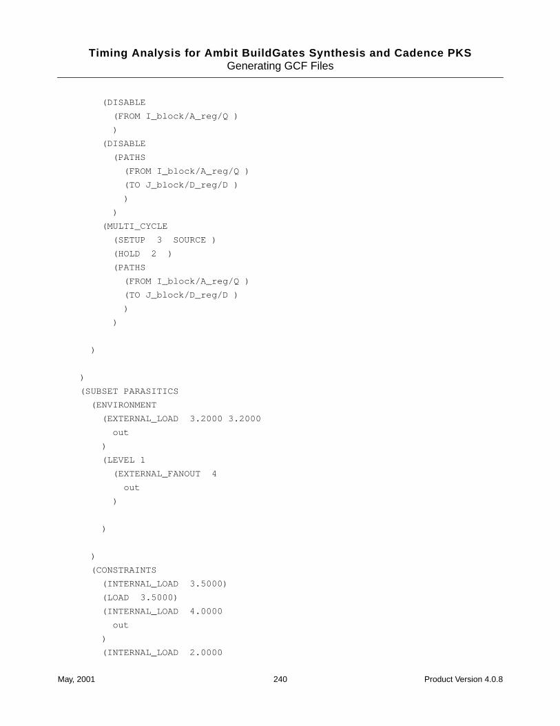
Timing Analysis for Ambit BuildGates Synthesis and Cadence PKSGenerating GCF Files
(DISABLE
(FROM I_block/A_reg/Q )
)
(DISABLE
(PATHS
(FROM I_block/A_reg/Q )
(TO J_block/D_reg/D )
)
)
(MULTI_CYCLE
(SETUP 3 SOURCE )
(HOLD 2 )
(PATHS
(FROM I_block/A_reg/Q )
(TO J_block/D_reg/D )
)
)
)
)
(SUBSET PARASITICS
(ENVIRONMENT
(EXTERNAL_LOAD 3.2000 3.2000
out
)
(LEVEL 1
(EXTERNAL_FANOUT 4
out
)
)
)
(CONSTRAINTS
(INTERNAL_LOAD 3.5000)
(LOAD 3.5000)
(INTERNAL_LOAD 4.0000
out
)
(INTERNAL_LOAD 2.0000
May, 2001 240 Product Version 4.0.8
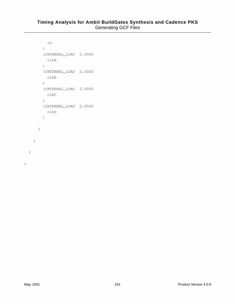
Timing Analysis for Ambit BuildGates Synthesis and Cadence PKSGenerating GCF Files
in
)
(INTERNAL_LOAD 2.0000
clkA
)
(INTERNAL_LOAD 2.0000
clkB
)
(INTERNAL_LOAD 2.0000
clkC
)
(INTERNAL_LOAD 2.0000
clkD
)
)
)
)
)
May, 2001 241 Product Version 4.0.8

Timing Analysis for Ambit BuildGates Synthesis and Cadence PKSGenerating GCF Files
May, 2001 242 Product Version 4.0.8
Timing Analysis for Ambit BuildGates Synthesis and Cadence PKS
CUnderstanding Errors and Warnings
This chapter lists some of the Cadence® timing analysis error and warning messages withprobable causes and corrections.
■ Error Messages on page 244
❑ Constraint Error Messages on page 244
❑ False Path Analysis Error Messages on page 244
May, 2001 243 Product Version 4.0.8
Timing Analysis for Ambit BuildGates Synthesis and Cadence PKSUnderstanding Errors and Warnings
Error Messages
Error messages cannot be ignored. The errors prevent timing analysis from completing.
Constraint Error Messages
TCLCMD-419
Can not set constraint_name constraint on hierarchical port hier_port_name ’
This message results when you try to apply a primary IO port constraint to a hierarchical port.There are three ways to overcome this error, generally the first one is best:
■ You can set the constraint on the leaf pin directly connected to the hierarchical port. Youmust also set_false_path -to leaf_pin to block incoming signals to the leaf pin.
■ You can set the constraint on the top level port. This is then propagated through simplecombinational gates and hierarchy. You can use the report_fanin command to findthe top level port name.
■ You can change the current and top_timing module before applying the constraint.
False Path Analysis Error Messages
Here are some examples of the error messages produced if you use the false path analysisoptions incorrectly.
Output of report_timing -false_path_analysisreport_timing -false_path_anaylsis
==> ERROR: No value provided for option ’-false_path_anaylsis’ <TCLCMD-166>.
You must specify static or robust analysis type.
Output of report_timing -false_path_analysis statreport_timing -false_path_anaylsis stat
==> ERROR: Unknown option ’stat’ <TCLCMD-112>.
You must spell out static , no abbreviation is taken.
May, 2001 244 Product Version 4.0.8
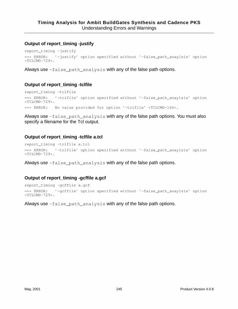
Timing Analysis for Ambit BuildGates Synthesis and Cadence PKSUnderstanding Errors and Warnings
Output of report_timing -justifyreport_timing -justify
==> ERROR: ’-justify’ option specified without ’-false_path_anaylsis’ option<TCLCMD-729>.
Always use -false_path_analysis with any of the false path options.
Output of report_timing -tclfilereport_timing -tclfile
==> ERROR: ’-tclfile’ option specified without ’-false_path_anaylsis’ option<TCLCMD-729>.
==> ERROR: No value provided for option ’-tclfile’ <TCLCMD-166>.
Always use -false_path_analysis with any of the false path options. You must alsospecify a filename for the Tcl output.
Output of report_timing -tclfile a.tclreport_timing -tclfile a.tcl
==> ERROR: ’-tclfile’ option specified without ’-false_path_anaylsis’ option<TCLCMD-729>.
Always use -false_path_analysis with any of the false path options.
Output of report_timing -gcffile a.gcfreport_timing -gcffile a.gcf
==> ERROR: ’-gcffile’ option specified without ’-false_path_anaylsis’ option<TCLCMD-729>.
Always use -false_path_analysis with any of the false path options.
May, 2001 245 Product Version 4.0.8

Timing Analysis for Ambit BuildGates Synthesis and Cadence PKSUnderstanding Errors and Warnings
May, 2001 246 Product Version 4.0.8
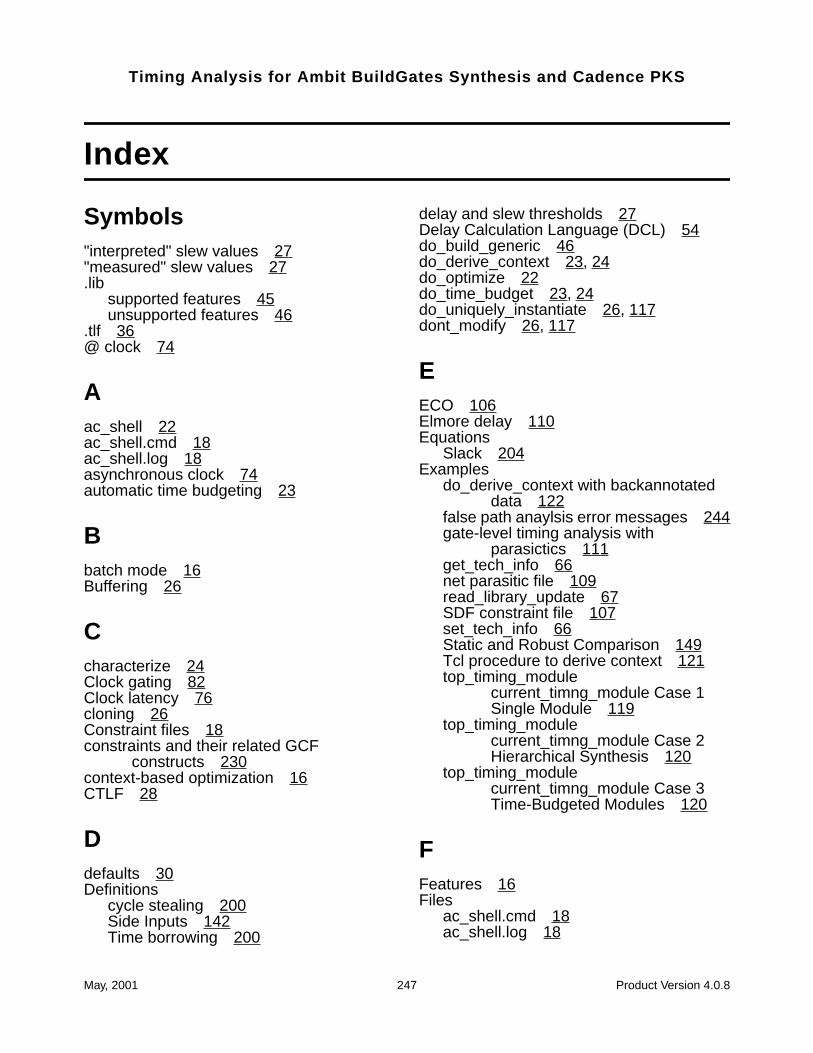
Timing Analysis for Ambit BuildGates Synthesis and Cadence PKS
Index
Symbols"interpreted" slew values 27"measured" slew values 27.lib
supported features 45unsupported features 46
.tlf 36@ clock 74
Aac_shell 22ac_shell.cmd 18ac_shell.log 18asynchronous clock 74automatic time budgeting 23
Bbatch mode 16Buffering 26
Ccharacterize 24Clock gating 82Clock latency 76cloning 26Constraint files 18constraints and their related GCF
constructs 230context-based optimization 16CTLF 28
Ddefaults 30Definitions
cycle stealing 200Side Inputs 142Time borrowing 200
delay and slew thresholds 27Delay Calculation Language (DCL) 54do_build_generic 46do_derive_context 23, 24do_optimize 22do_time_budget 23, 24do_uniquely_instantiate 26, 117dont_modify 26, 117
EECO 106Elmore delay 110Equations
Slack 204Examples
do_derive_context with backannotateddata 122
false path anaylsis error messages 244gate-level timing analysis with
parasictics 111get_tech_info 66net parasitic file 109read_library_update 67SDF constraint file 107set_tech_info 66Static and Robust Comparison 149Tcl procedure to derive context 121top_timing_module
current_timng_module Case 1Single Module 119
top_timing_modulecurrent_timng_module Case 2Hierarchical Synthesis 120
top_timing_modulecurrent_timng_module Case 3Time-Budgeted Modules 120
FFeatures 16Files
ac_shell.cmd 18ac_shell.log 18
May, 2001 247 Product Version 4.0.8
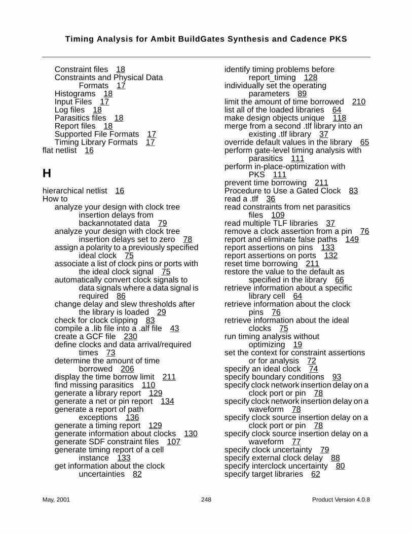
Timing Analysis for Ambit BuildGates Synthesis and Cadence PKS
Constraint files 18Constraints and Physical Data
Formats 17Histograms 18Input Files 17Log files 18Parasitics files 18Report files 18Supported File Formats 17Timing Library Formats 17
flat netlist 16
Hhierarchical netlist 16How to
analyze your design with clock treeinsertion delays frombackannotated data 79
analyze your design with clock treeinsertion delays set to zero 78
assign a polarity to a previously specifiedideal clock 75
associate a list of clock pins or ports withthe ideal clock signal 75
automatically convert clock signals todata signals where a data signal isrequired 86
change delay and slew thresholds afterthe library is loaded 29
check for clock clipping 83compile a .lib file into a .alf file 43create a GCF file 230define clocks and data arrival/required
times 73determine the amount of time
borrowed 206display the time borrow limit 211find missing parasitics 110generate a library report 129generate a net or pin report 134generate a report of path
exceptions 136generate a timing report 129generate information about clocks 130generate SDF constraint files 107generate timing report of a cell
instance 133get information about the clock
uncertainties 82
identify timing problems beforereport_timing 128
individually set the operatingparameters 89
limit the amount of time borrowed 210list all of the loaded libraries 64make design objects unique 118merge from a second .tlf library into an
existing .tlf library 37override default values in the library 65perform gate-level timing analysis with
parasitics 111perform in-place-optimization with
PKS 111prevent time borrowing 211Procedure to Use a Gated Clock 83read a .tlf 36read constraints from net parasitics
files 109read multiple TLF libraries 37remove a clock assertion from a pin 76report and eliminate false paths 149report assertions on pins 133report assertions on ports 132reset time borrowing 211restore the value to the default as
specified in the library 66retrieve information about a specific
library cell 64retrieve information about the clock
pins 76retrieve information about the ideal
clocks 75run timing analysis without
optimizing 19set the context for constraint assertions
or for analysis 72specify an ideal clock 74specify boundary conditions 93specify clock network insertion delay on a
clock port or pin 78specify clock network insertion delay on a
waveform 78specify clock source insertion delay on a
clock port or pin 78specify clock source insertion delay on a
waveform 77specify clock uncertainty 79specify external clock delay 88specify interclock uncertainty 80specify target libraries 62
May, 2001 248 Product Version 4.0.8
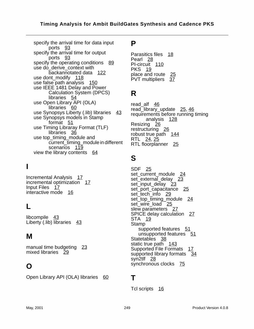
Timing Analysis for Ambit BuildGates Synthesis and Cadence PKS
specify the arrival time for data inputports 93
specify the arrival time for outputports 93
specify the operating conditions 89use do_derive_context with
backannotated data 122use dont_modify 118use false path analysis 150use IEEE 1481 Delay and Power
Calculation System (DPCS)libraries 54
use Open Library API (OLA)libraries 60
use Synopsys Liberty (.lib) libraries 43use Synopsys models in Stamp
format 51use Timing Libraray Format (TLF)
libraries 36use top_timing_module and
current_timing_module in differentscenarios 119
view the library contents 64
IIncremental Analysis 17incremental optimization 17Input Files 17interactive mode 16
Llibcompile 43Liberty (.lib) libraries 43
Mmanual time budgeting 23mixed libraries 29
OOpen Library API (OLA) libraries 60
PParasitics files 18Pearl 28PI-circuit 110PKS 19place and route 25PVT multipliers 37
Rread_alf 46read_library_update 25, 46requirements before running timing
analysis 128Resizing 26restructuring 26robust true path 144RTL 24, 25RTL floorplanner 25
SSDF 25set_current_module 24set_external_delay 23set_input_delay 23set_port_capacitance 25set_tech_info 29set_top_timing_module 24set_wire_load 25slew parameters 27SPICE delay calculation 27STA 19Stamp
supported features 51unsupported features 51
Statetables 38static true path 143Supported File Formats 17supported library formats 34syn2tlf 28synchronous clocks 75
TTcl scripts 16
May, 2001 249 Product Version 4.0.8
Timing Analysis for Ambit BuildGates Synthesis and Cadence PKS
threshold definitions 27Threshold-based degradation 29time budgeting 23Time-driven logic optimization 116timing context 116timing convergence 102Timing Library Format (TLF) 36Tips
ideal clocks 75tradeoffs 21Truthtables 38
Uunits 30
Vvirtual clock 74
Wwrite_assertions 23
May, 2001 250 Product Version 4.0.8