Embed Size (px)
Citation preview

HE S Series TUBE-ICE MACHINE
Service Manual
$5000

NOTICE
This manual is the property of the owner of this particular Tube-Ice®
machine.
Model #____________________ Serial #____________________.
It is to be left on the premises with this machine at all times. After start-
up, it should be stored in a safe place where it can be readily available
when needed for future reference in maintaining troubleshooting or
servicing.
Failure to comply with this notice will result in unnecessary
inconvenience and possible additional expenses.
This manual is intended as an informational tool for the installation,
operation, maintenance, troubleshooting, and servicing of this
equipment. If an existing situation calls for additional information not
found herein, we suggest that you contact your distributor first. If
further assistance or information is needed, please feel free to contact the
factory at 502-635-3000 or FAX at 502-635-3024.
IMPORTANT: The Warranty Registration/Start-Up Report found in the
front of this manual is to be completed and returned to the factory
promptly after the official start-up.
Please return to: VOGT ICE, LLC
1000 W. Ormsby Ave.
Louisville, KY 40210

map-10/15/13
Warranty Registration/Start-Up Form HES20, HES30, HES40, HE60
Model Number: __________________________ Serial Number: ____________________
This form must be filled out and sent to Vogt in order to activate warranty.
Date of Start-Up: ___________________ Form Completed By: ________________________________
AC Condenser Model Number: ____________________ AC Condenser Serial Number: ________________________
Service Company
Company Name: ____________________________________________ Phone: _______________________
Address: ____________________________________ City: _________________________ State: ___________ Zip: _______
Customer (location of equipment)
Company Name: ___________________________________________________ City _______________________ State _____
PRE-OPERATION CHECK
______ V _____ PH _____ HZ Power (check supply (actual) at machine)—Notice: Call Vogt if under 195 V
Compressor Amps (check at the start of freeze cycle) L1________ L2 ________ L3 ________
Cutter Motor Amps _______ Water Pump Motor Amps _______
AC condenser cold weather temperature setting (s) Solenoid ________ Fan (HES30, HES40 & HE60 only)_______
AC condenser installed above machine: Yes No Approx. _____ ft.
AC condenser properly piped—are all lines insulated (see installation and start-up instructions)?
AC condenser line length (in equivalent feet (see installation instructions)) ____________
Leak checked entire system including AC condenser and lines (if applicable)
Compressor oil level, i.e. 1/4 – 1/2 – 3/4: ______
Average hole diameter of ice ______ Crushed Ice thickness ______ Clear ice Yes No
Instruction manual and warranty certificate left on-site Name of person left with: ____________________________
Problems Encountered: _______________________________________________________________________________________________________________
_______________________________________________________________________________________________________________
_______________________________________________________________________________________________________________
Comments: _____________________________________________________________________________________________________________________________
_______________________________________________________________________________________________________________
_______________________________________________________________________________________________________________
Technician Signature: ________________________________________ Date: ______________________________________________
Return Form in postage paid envelope or Fax 502-635-3024
Vogt Order Number: _____________
Vogt Ice LLC
1000 West Ormsby Ave
Louisville, KY 40210
Phone: 502-635-3000
Fax: 502-635-3024

5/24/11
Blank page

VOGT ICE, LLC, located in
Louisville, Kentucky since 1880.
Sales - (800) 959-8648
Service - (502) 635-3000
Parts - Your Local Distributor
Call your local distributor first for all of your parts and service needs.
Since 1880, Manufacturers of Quality
Tube-Ice® Machines


HES Series Service Manual
TABLE OF CONTENTS
5/24/11
i
Table Of Contents
Models HES-20, HES-30 & HES-40
Page No. 1. INTRODUCTION
A Brief History of Our Company ................................................................................................................ 1-1
Vogt Energy-Saving Tube-Ice® Machines................................................................................................... 1-1
Preview .................................................................................................................................................... 1-1
Important Safety Notice............................................................................................................................... 1-2
Special precautions to be observed when charging refrigeration systems ................................................... 1-2
Safety Symbols & What They Mean ........................................................................................................... 1-3
2. RECEIPT OF YOUR TUBE-ICE® MACHINE
Inspection ................................................................................................................................................... 2-1
Safety Valves............................................................................................................................................... 2-2
Machine Room ............................................................................................................................................ 2-2
Storage .................................................................................................................................................... 2-2
3. HOW YOUR TUBE-ICE® MACHINE WORKS
Principle of Operation ................................................................................................................................. 3-1
Air Cooled Piping Diagram, FIGURE 3-1 .................................................................................................. 3-2
Water Cooled Piping Diagram, FIGURE 3-2.............................................................................................. 3-2
Piping Schematic Nomenclature.................................................................................................................. 3-3
How Ice Is Stored
Bin Control Sensor Installation, FIGURE 3-3............................................................................................. 3-4
Storing Ice ................................................................................................................................................... 3-4
Ice Bin Capacity .......................................................................................................................................... 3-4
When Ice Bin Thermostats Are Not Used ................................................................................................... 3-5
Single Ice .................................................................................................................................................... 3-5
Dual Ice .................................................................................................................................................... 3-5
Crushed Ice Preferred.................................................................................................................................. 3-5
4. ELECTRICAL CONTROLS & THEIR FUNCTIONS
Control Panel, FIGURE 4-1A ..................................................................................................................... 4-1
Control Panel with Hoffman Enclosure, FIGURE 4-1B.............................................................................. 4-1
Control Panel Part Numbers, TABLE 4-1................................................................................................... 4-2
Description of Control Panel Parts .............................................................................................................. 4-3
Wiring and Electrical Connections, FIGURE 4-2 ....................................................................................... 4-5
Electrical Specifications, TABLE 4-2 ......................................................................................................... 4-5
ii HE S Series Service Manual
TABLE OF CONTENT
10/16/13
Page No.
4. ELECTRICAL CONTROLS & THEIR FUNCTIONS (Cont.)
PLC Features & Functions........................................................................................................................... 4-6
PLC Display, FIGURE 4-3 .......................................................................................................................... 4-6
PLC Inputs & Outputs, TABLE 4-3 ..................................................................................................... 4-6
PLC Start-Up Mode ............................................................................................................................. 4-7
PLC Stand-By Mode ............................................................................................................................ 4-7
PLC Freeze Mode ................................................................................................................................ 4-7
PLC Harvest Mode ............................................................................................................................... 4-7
PLC Partial Pump-Down Mode ............................................................................................................ 4-7
PLC Partial Pump-Down Time, TABLE 4-4........................................................................................ 4-7
PLC Total Pump-Down Mode .............................................................................................................. 4-7
PLC Clean Mode .................................................................................................................................. 4-8
PLC Fault Mode ................................................................................................................................... 4-8
PLC Fault Codes, TABLE 4-5 ............................................................................................................. 4-8
Copeland Performance Alert ....................................................................................................................... 4-9
Copeland Performance Alert wiring, FIGURE 4-4 ..................................................................................... 4-9
Copeland Performance Alert Codes & Lockout Configuration, TABLE 4-6 .............................................. 4-9
Machine Fault Startup Sequence, FIGURE 4-5 ........................................................................................... 4-10
Fault Indicator / Selector Switch Location, FIGURE 4-6 ............................................................................ 4-10
Dual Ice Machine (200V/208-230V) Wiring Schematic, FIGURE 4-7 ...................................................... 4-11
Single Ice Machine (200V/208-230V) Wiring Schematic, FIGURE 4-8 .................................................... 4-12
Dual Ice Machine (400V/460V) Wiring Schematic, FIGURE 4-9 .............................................................. 4-13
Single Ice Machine (400V/460V) Wiring Schematic, FIGURE 4-10 ......................................................... 4-14
Air Cooled Condenser Wiring Schematic (Single Fan – 50/50 Split), FIGURE 4-11 ................................. 4-15
Air Cooled Condenser Wiring Schematic (Single Fan – 50/25/25 Split), FIGURE 4-12 ............................ 4-16
Air Cooled Condenser Wiring Schematic (Dual Fan – 50/50 Split), FIGURE 4-13 ................................... 4-17
5. MAINTENANCE
Ice-making Section ...................................................................................................................................... 5-1
Cleaning Procedure ..................................................................................................................................... 5-1
Sanitizing Procedure .................................................................................................................................... 5-2
Water Distributors, FIGURE 5-1................................................................................................................. 5-4
Water Distributors, Freezer Cover, Gasket Part #'s, TABLE 5-1 ................................................................ 5-4
Water Tank .................................................................................................................................................. 5-5
Drip Pan .................................................................................................................................................... 5-5
Water Cooled Condensers ........................................................................................................................... 5-5
Draining the Condenser ............................................................................................................................... 5-6
Chemical Cleaning the Condenser ............................................................................................................... 5-6

HES Series Service Manual
TABLE OF CONTENTS
5/24/11
iii
Page No.
5. MAINTENANCE (Cont.)
Mechanical Cleaning the Condenser ........................................................................................................... 5-6
Part I..................................................................................................................................................... 5-6
Part II ................................................................................................................................................... 5-7
Replacement Gaskets, TABLE 5 -2............................................................................................................. 5-7
Air-Cooled Condenser Cleaning.................................................................................................................. 5-8
Compressor Oil............................................................................................................................................ 5-8
Cutter Gear Reducer Oil .............................................................................................................................. 5-8
Preventive Maintenance .............................................................................................................................. 5-9
Daily Checklist ............................................................................................................................................ 5-9
Note To Manager or Owner ........................................................................................................................ 5-9
Preventive Maintenance Program................................................................................................................ 5-10
6. TROUBLESHOOTING
Machine Faults ............................................................................................................................................ 6-1
PLC Fault Codes, TABLE 6-1 .................................................................................................................... 6-1
Machine Fault Indicator Light, FIGURE 6-1 .............................................................................................. 6-2
Machine Fault Startup Sequence, FIGURE 6-2........................................................................................... 6-2
PLC, FIGURE 6-3....................................................................................................................................... 6-3
PLC Inputs and Outputs, TABLE 6-2 ......................................................................................................... 6-3
Machine Will Not Run ................................................................................................................................ 6-4
Checking PLC ............................................................................................................................................. 6-4
Low Ice Capacity......................................................................................................................................... 6-5
Fault # 1, High/Low Pressure during Freeze ............................................................................................... 6-6
Fault # 2, High/Low Pressure during Harvest.............................................................................................. 6-7
Fault # 3, High/Low Pressure during Partial Pumpdown............................................................................. 6-7
Fault # 4, High/Low Pressure during Total Pumpdown .............................................................................. 6-8
Fault # 5, Short Cycle Fault......................................................................................................................... 6-9
Fault # 6, Long Cycle Fault ......................................................................................................................... 6-9
Fault # 7, Pump Motor Overload Fault........................................................................................................ 6-10
Fault # 8, Cutter Motor Overload Fault ....................................................................................................... 6-10
7. SERVICE OPERATIONS
Machine Component Layout (Front View), FIGURE 7-1A ........................................................................ 7-1
Machine Component Layout (Side View), FIGURE 7-1B .......................................................................... 7-1
Machine Component Layout (Rear View - WC), FIGURE 7-1C................................................................ 7-2
Machine Component Layout (Rear View - AC), FIGURE 7-1D................................................................. 7-2
Adjustable Blowdown (For Clearer Ice)...................................................................................................... 7-3

iv HE S Series Service Manual
TABLE OF CONTENT
5/24/11
Page No.
7. SERVICE OPERATIONS (Cont.)
Automatic Blowdown (Harvest Cycle), FIGURE 7-2 ................................................................................. 7-3
Float Valve (Make-Up Water), FIGURE 7-3 .............................................................................................. 7-4
Circulating Water Pump, FIGURE 7-4........................................................................................................ 7-4
Circulating Water Pump Replacement Parts, TABLE 7-1........................................................................... 7-5
Water Distributors, TABLE 7-2 .................................................................................................................. 7-5
Freezer Cover, Gasket, FIGURE 7-5........................................................................................................... 7-5
Water Tank.................................................................................................................................................. 7-6
Cutter-Water Tank Assembly, FIGURE 7-6................................................................................................ 7-6
Cutter Gear Reducer .................................................................................................................................... 7-6
Gear Reducer Replacement ......................................................................................................................... 7-7
Cutter Bearing ............................................................................................................................................. 7-7
Cutter and Gear Drive ................................................................................................................................. 7-7
Ice Discharge Arrangement, FIGURE 7-7................................................................................................... 7-8
Cutter-Water Tank Parts, FIGURE 7-8 ....................................................................................................... 7-9
Cutter Drive Parts, FIGURE 7-9 ................................................................................................................. 7-10
Cutter Parts, FIGURE 7-10 ......................................................................................................................... 7-11
Thermal Expansion Valve, FIGURE 7-11................................................................................................... 7-12
TXV Part #'s, TABLE 7-3........................................................................................................................... 7-12
Checking Superheat..................................................................................................................................... 7-12
Recommended Superheat Setting, TABLE 7-4 ........................................................................................... 7-13
Expansion Valve Adjustment Procedure & Installation .............................................................................. 7-13
Solenoid Valves, FIGURE 7-12 .................................................................................................................. 7-14
Solenoid Valves Parts, TABLE 7-5............................................................................................................. 7-14
Freezer Pressure Switches ........................................................................................................................... 7-15
Freezer Pressure Switch (Allen-Bradley), FIGURE 7-13............................................................................ 7-15
High/Low Pressure Switch, FIGURE 7-14.................................................................................................. 7-16
Head Pressure.............................................................................................................................................. 7-17
Air-Cooled Units ......................................................................................................................................... 7-17
Condenser Fan Switch, FIGURE 7-15 ........................................................................................................ 7-17
Air Cooled Condenser Cleaning.................................................................................................................. 7-17
Kramer Cold Weather Kit Replacement Parts, TABLE 7-6........................................................................ 7-17
Air Cooled Condenser Data, TABLE 7-7.................................................................................................... 7-18
Condenser Dimensions, FIGURE 7-16 ....................................................................................................... 7-18
Condenser Wiring, FIGURE 7-17 ............................................................................................................... 7-19
Water Cooled Units ..................................................................................................................................... 7-19
Water Regulating Valve, FIGURE 7-18...................................................................................................... 7-19

HES Series Service Manual
TABLE OF CONTENTS
5/24/11
v
Page No.
7. SERVICE OPERATIONS (Cont.)
Water Regulating Valve Part #'s, TABLE 7-8............................................................................................. 7-19
Water Cooled Condenser Service................................................................................................................ 7-20
Compressor Crankcase Heater, TABLE 7-9................................................................................................ 7-20
Compressor Motor Rotation ........................................................................................................................ 7-20
Scroll Compressor, FIGURE 7-19 .............................................................................................................. 7-21
Compressor Info, TABLE 7-10 ................................................................................................................... 7-21
Compressor Suction Rota-lock Valve, FIGURE 7-20, TABLE 7-11 .......................................................... 7-22
Compressor Discharge Rota-lock Valve, FIGURE 7-21, TABLE 7-12 ...................................................... 7-23
Short Circuit Protection, FIGURE 7-22 ...................................................................................................... 7-24
Control Circuit Protection ........................................................................................................................... 7-24
Motor Short Circuit Protection.................................................................................................................... 7-25
Motor Over Current Protection ................................................................................................................... 7-25
Overload Heater Pack Settings, TABLE 7-13 ............................................................................................. 7-25
Motor Overloads, FIGURE 7-23 ................................................................................................................ 7-25
Ice Bin Control, FIGURE 7-24 ................................................................................................................... 7-26
Programming Electronic Bin Thermostat .................................................................................................... 7-26
Bin Thermostat Mounting Location, FIGURE 7-25.................................................................................... 7-27
Electronic Bin Thermostat Error Messages ................................................................................................. 7-27
Thawing Timer, FIGURE 7-26.................................................................................................................... 7-28
Thawing Timer ............................................................................................................................................ 7-28
Selector Switch, FIGURE 7-27 ................................................................................................................... 7-28
Pumping Down Freezer ............................................................................................................................... 7-29
Pumping Down Entire System..................................................................................................................... 7-29
Removal of Refrigerant From the Machine ................................................................................................. 7-29
Refrigerant Leaks ........................................................................................................................................ 7-30
Non-Condensable Gases.............................................................................................................................. 7-30
Compressor Motor Burnout......................................................................................................................... 7-30
Cylinder Ice to Crushed Ice Conversion...................................................................................................... 7-31
Cylinder to Crushed, Terminal Block jumper Locations, FIGURE 7-28 .................................................... 7-31
Recommended Freezer Pressure Setting, TABLE 7-14............................................................................... 7-31
Freezer Pressure Switch, FIGURE 7-29 ...................................................................................................... 7-31
Recommended Ice Weights/Cycle, TABLE 7-15........................................................................................ 7-31
Single to Dual Ice Conversion..................................................................................................................... 7-31
Defrost Pressure Switch (DPS), FIGURE 7-30 ........................................................................................... 7-32
Defrost Pressure Switch Wiring, FIGURE 7-31.......................................................................................... 7-32
Oil Separator, FIGURE 7-32....................................................................................................................... 7-33

vi HE S Series Service Manual
TABLE OF CONTENT
5/24/11
Page No.
8. MODEL NUMBER STRUCTURE FOR HES MACHINES................................................................. 8-1
9. TABLES AND CHARTS
Ice Capacity TABLE 9-1............................................................................................................................. 9-1
Normal Operating Vitals, TABLE 9-2 ........................................................................................................ 9-1
Temperature-Pressure Chart, TABLE 9-3 ................................................................................................... 9-2
English-Metric Conversion, TABLE 9-4..................................................................................................... 9-3
Constants, TABLE 9-5 ................................................................................................................................ 9-3
10. TECHNICAL SERVICE BULLETINS ................................................................................................ 10-1
11. INDEX .................................................................................................................................................... 11-1

HES Series Service Manual
INTRODUCTION
10/15/13
1-1
1. Introduction
Henry Vogt Machine Co.
A Brief History Of Our Company. Henry Vogt Machine Co. was founded as a small machine
shop in Louisville, Kentucky in 1880. In 1938, Vogt built the first Tube-Ice® machine and
revolutionized the ice-making industry. Our first “sized-ice” machine quickly replaced the old can-
ice plants, which required much hard labor and large amounts of floor space for freezing, cutting,
and crushing ice by hand.
Today, Vogt Ice, LLC carries on the tradition as one of the world's leading producers of ice-making
equipment.
Vogt Energy-Saving Tube-Ice Machines Are Cost Effective. Today, Vogt Tube-Ice® machines
enjoy a well-earned reputation as the most energy efficient, dependable ice-making equipment in the
world.
Using as little as one-half to one-third the energy required by competitors’ ice makers, Tube-Ice®
machines produce the same amount of ice--in restaurants, sports arenas, packing plants, and
wholesale operations around the globe--at great savings.
In addition, Tube-Ice® machines are renowned for their long life, giving many customers more than
35 years of dependable service. Ask someone who owns one.
Preview. All the skill in engineering and fabrication that we’ve learned in over a century of
experience is reflected in the HES model Tube-Ice® machines. Since Vogt introduced Tube-Ice®
machines in 1938, the process of making Tube-Ice® ice has been widely recognized as the most
economical means of production. The machine’s economic and reliable operation have been proven
over and over again, in a network of varied types of installations throughout the world.
Furnished with your machine is the Certificate Of Test--the report of operating data which is a
record of the unit’s satisfactory operation at our factory test floor. It is evidence of our desire to
deliver to you “the finest ice-making unit ever made.”
This manual is designed to assist you in the operation and maintenance of your unit. Your Tube-Ice®
machine will give you a lifetime of service when you install it, maintain it, and service it properly.
Please read your manual carefully before attempting installation, operation, or servicing of this
professionally-designed piece of equipment. Also, make sure the Warranty Registration/Start-up
Report is completed and returned.
If you have additional questions, please call your distributor. Also, feel free to phone the factory
direct at (502) 635-3000 or 1-800-853-8648.

HES Series Service Manual
INTRODUCTION
10/15/13
1-2
Important Safety Notice. This information is intended for use by individuals possessing adequate
backgrounds of electrical, refrigeration and mechanical experience. Any attempt to repair major
equipment may result in personal injury and property damage. The manufacturer or seller cannot be
responsible for the interpretation of this information, nor can it assume any liability in connection
with its use.
Special Precautions To Be Observed When Charging Refrigeration Systems. Only technically-
qualified persons, experienced and knowledgeable in the handling of refrigerant and operation of
refrigeration systems, should perform the operations described in this manual. All local, federal, and
EPA regulations must be strictly adhered to when handling refrigerants.
If a refrigeration system is being charged from refrigerant cylinders, disconnect each cylinder when
empty or when the system is fully charged. A gage should be installed in the charging line to
indicate refrigerant cylinder pressure. The cylinder may be considered empty of liquid refrigerant
when the gauge pressure is 25 pounds or less, and there is no frost on the cylinder. Close the
refrigerant charging valve and cylinder valve before disconnecting the cylinder. Loosen the union in
the refrigerant charging line--carefully to avoid unnecessary and illegal release of refrigerant into the
atmosphere.
! CAUTION !
Immediately close system charging valve at commencement of defrost or thawing cycle if refrigerant cylinder is connected. Never leave a refrigerant cylinder connected to system except during charging operation. Failure to observe either of these precautions can result in transferring refrigerant from the system to the refrigerant cylinder, over-filling it, and possibly causing the cylinder to rupture because of pressure from expansion of the liquid refrigerant brought on by an increase in temperature.
! CAUTION !
Always store cylinders containing refrigerant in a cool place. They should never be exposed to
temperatures higher than 120°F (R-22) or 108°F (R-404A) and should be stored in a manner to
prevent abnormal mechanical shocks.
Also, transferring refrigerant from a refrigeration system into a cylinder can be very dangerous and
is not recommended.
! CAUTION !
It is not recommended that refrigerant be transferred from a refrigeration system directly into a cylinder. If such a transfer is made, the refrigerant cylinder must be an approved, CLEAN cylinder--free of any contaminants or foreign materials--and must be connected to an approved recovery mechanism with a safety shutoff sensor to assure contents do not exceed net weight specified by cylinder manufacturer or any applicable code requirements.
! CAUTION !

HES Series Service Manual
INTRODUCTION
3/25/08
1-3
Safety Symbols & What They Mean. Prior to installation or operation of the Tube-Ice® machine, please read this manual. Are you familiar with the installation, start-up, and operation of a Tube-Ice® machine? Before you operate, adjust or service this machine, you should read this manual, understand the operation of this machine, and be aware of possible dangers.
These safety symbols will alert you
when special care is needed.
Please heed.
! DANGER ! Indicates an immediate hazard and that special precautions
are necessary to avoid severe personal injury or death. ! DANGER !
! WARNING ! Indicates a strong possibility of a hazard and that an unsafe practice could result in severe personal injury.
! WARNING !
! CAUTION ! Means hazards or unsafe practices could result
in personal injury or product or property damage. ! CAUTION !

3/25/08
HES Series Service Manual
RECEIPT OF YOUR TUBE-ICE MACHINE
10/16/13
2-1
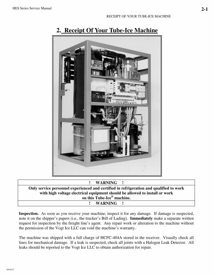
2. Receipt Of Your Tube-Ice Machine
! WARNING !
Only service personnel experienced and certified in refrigeration and qualified to work with high voltage electrical equipment should be allowed to install or work
on this Tube-Ice® machine.
! WARNING !
Inspection. As soon as you receive your machine, inspect it for any damage. If damage is suspected,
note it on the shipper’s papers (i.e., the trucker’s Bill of Lading). Immediately make a separate written
request for inspection by the freight line’s agent. Any repair work or alteration to the machine without
the permission of the Vogt Ice LLC can void the machine’s warranty.
The machine was shipped with a full charge of HCFC-404A stored in the receiver. Visually check all
lines for mechanical damage. If a leak is suspected, check all joints with a Halogen Leak Detector. All
leaks should be reported to the Vogt Ice LLC to obtain authorization for repair.

2-2 HES Series Service Manual
RECEIPT OF YOUR TUBE-ICE MACHINE
10/16/13
Safety Valves. Two safety pressure relief valves are an integral part of the packaged Tube-Ice®
machine. One is located in the low side of the system in the suction line between the freezer and the
suction stop valve and one is in the high side of the system on the receiver. You must vent each of the
pressure relief valves to the atmosphere in such a manner as to comply with local and national codes.
Machine Room. The machine must be located inside a suitable building and must not be subjected to
ambient temperatures below 50°F (10°C) or above 110°F (43.3°C). Heat radiation from other sources
(sunlight, furnaces, condenser, etc.) and unusual air current may affect the operation of the machine and
should be avoided. The electrical components of the Tube-Ice® machine are rated NEMA 1. Therefore, the machine should not be located in a hazardous area. Storage (prior to installation or start-up). The machine must not be stored or installed in an area that
is subject to reach temperatures at or above 115°F (46.1°C).
Important Notice. The Warranty/Registration Start-Up Report must be completed and
returned to the Vogt Ice LLC to initiate and assure a full warranty.
HES Series Service Manual
HOW YOUR TUBE-ICE MACHINE WORKS
3/25/08
3-1
3. How Your Tube-Ice Machine Works
Principle Of Operation. The selector switch located on the switch plate of the freezing unit controls the manual operation of the machine. With the selector switch in the “Ice” position, the machine is controlled by the PLC and ice bin controls, which will automatically stop and start the freezing unit by the level of the ice in the storage bin. With Dual Ice machines, the type ice produced (cylinder or crushed) is determined by the position of the selector switch located in the switch plate. For Single Type Ice machines, a jumper in the control panel determines the type of ice produced. (See Electrical Controls for details)
The control wiring is arranged so that the unit will stop only upon the completion of a thawing period and partial pump down cycle whether by putting the selector switch in the “Off” position or the ice bin controls.
The selector switch should be put in the “Clean” position only when the equipment is to be cleaned or pumped down as outlined in the “Cleaning Procedure,” and “Total Pump-Down Procedure”, Section 7, and instructions attached to the machine.
If it should become necessary to instantly stop the machine, the external disconnect switch (supplied by customer) must be turned off.
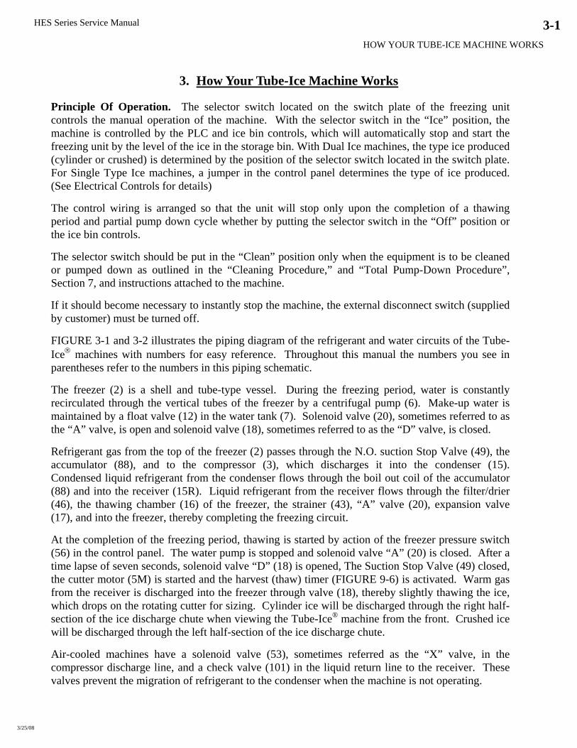
FIGURE 3-1 and 3-2 illustrates the piping diagram of the refrigerant and water circuits of the Tube-Ice® machines with numbers for easy reference. Throughout this manual the numbers you see in parentheses refer to the numbers in this piping schematic.
The freezer (2) is a shell and tube-type vessel. During the freezing period, water is constantly recirculated through the vertical tubes of the freezer by a centrifugal pump (6). Make-up water is maintained by a float valve (12) in the water tank (7). Solenoid valve (20), sometimes referred to as the “A” valve, is open and solenoid valve (18), sometimes referred to as the “D” valve, is closed.
Refrigerant gas from the top of the freezer (2) passes through the N.O. suction Stop Valve (49), the accumulator (88), and to the compressor (3), which discharges it into the condenser (15). Condensed liquid refrigerant from the condenser flows through the boil out coil of the accumulator (88) and into the receiver (15R). Liquid refrigerant from the receiver flows through the filter/drier (46), the thawing chamber (16) of the freezer, the strainer (43), “A” valve (20), expansion valve (17), and into the freezer, thereby completing the freezing circuit.
At the completion of the freezing period, thawing is started by action of the freezer pressure switch (56) in the control panel. The water pump is stopped and solenoid valve “A” (20) is closed. After a time lapse of seven seconds, solenoid valve “D” (18) is opened, The Suction Stop Valve (49) closed, the cutter motor (5M) is started and the harvest (thaw) timer (FIGURE 9-6) is activated. Warm gas from the receiver is discharged into the freezer through valve (18), thereby slightly thawing the ice, which drops on the rotating cutter for sizing. Cylinder ice will be discharged through the right half-section of the ice discharge chute when viewing the Tube-Ice® machine from the front. Crushed ice will be discharged through the left half-section of the ice discharge chute.
Air-cooled machines have a solenoid valve (53), sometimes referred as the “X” valve, in the compressor discharge line, and a check valve (101) in the liquid return line to the receiver. These valves prevent the migration of refrigerant to the condenser when the machine is not operating.
HES Series Service Manual HOW YOUR TUBE-ICE MACHINE WORKS
3-2
FIGURE 3-1 HES, Air Cooled –- Piping Schematic
FIGURE 3-2 HES, Water Cooled –- Piping Schematic

HES Series Service Manual
HOW YOUR TUBE-ICE MACHINE WORKS
3/25/08
3-3
PIPING SCHEMATIC NOMENCLATURE
2. Freezer 34. Compressor Suction Rota-lock Valve
3. Compressor 35. Compressor Discharge Rota-lock Valve
4PS. High/Low Pressure Safety Switch 39. Water Tank Drain Valve
5M. Cutter Motor 40. Automatic Blowdown Piping
5R. Cutter Gear Reducer 41. Condenser Water Regulator
6. Water Pump 41A. Fan Control Switch
7. Water Tank (reservoir) 43. Strainer (Liquid line & Oil return)
8. Freezer Cover 46. Filter Drier
12. Make-Up Float Valve 49. Suction Stop Valve
14. Oil Separator 50. Receiver Pressure Relief Valve
15. Condenser 51. Freezer Pressure Relief Valve
15R. Receiver 53. Discharge Solenoid Valve "X"
16. Thaw Chamber 56. Freezer Pressure Switch
17. Expansion Valve 58. Liquid Outlet Valve “King”
18. Thaw Gas Solenoid Valve “D” 70. Stop Valve (ball)
20. Liquid Line Solenoid Valve “A” 88. Accumulator
23. Condenser Water Inlet Connection 90A. Thaw Gas Stop Valve
23A. Make-Up Water Inlet Connection 90B. Thaw Gas / FPS Stop Valve
24. Condenser Water Out Connection 91. Liquid Return Stop
25. Water Tank Drain Connection 101. Check Valve
28. Refrigerant Charging Valve
30. Gage Glass
32. AC Condenser Service Connection

HES Series Service Manual HOW YOUR TUBE-ICE MACHINE WORKS
3-4
Storing Ice. When storing ice in a bin, make sure the bin control sensors are mounted in the bin properly. Dual ice machines require a storage bin with a divider and must have two bin controls.
A machine making one type of ice will not have a bin divider and will require only one bin control. If the machine is making cylinder ice, the sensor should be mounted on the right side of the bin. If making crushed ice, the sensor should be mounted on the left side of the bin.
FIGURE 3-3 Bin Control Sensor Installation
Ice Bin Capacity. Crushed or cylinder ice weighs approximately 35 pounds per cubic ft. (35 lb/ft3 ). As ice drops into a bin, it will pile up and slope naturally at about a 45° angle. This natural slope should be taken into account when locating the bin thermostat bulb (or other bin level control) and when calculating the normal bin capacity. If the ice is spread out by hand in the bin for maximum storage capacity, make sure a hazard is not created by allowing ice to back up into the chute and jamming the cutter. Always allow enough room below the chute for at least one harvest (cylinder ice = 42 lbs. / cycle , crushed ice = 31 lbs. / cycle).
If a two-way defector is installed below the ice chute, care should be taken to make sure it is located directly in the center of the stream of ice as it falls to give even distribution of the ice.

HES Series Service Manual
HOW YOUR TUBE-ICE MACHINE WORKS
10/16/13
3-5
When ice bin thermostats are NOT used. For Dual ice machines, with the selector switch SS2 set
on either “Auto” or “Cyl” ice, the machine will produce cylinder ice only. If the switch is changed to
“Cru” while the unit is producing cylinder ice, after the first 5 minutes of a cycle, it will complete the
freeze and harvest of cylinder ice before changing to the production of crushed ice. The next cycle
will produce crushed ice.
With the switch set on “Cru” the machine will produce crushed ice. If the switch is changed to “Auto”
or “Cyl” within the first 5 minutes of a cycle, the unit will revert immediately to the production of
cylinder ice.
If an alternate bin level control is used, it must be located in a position to stop the machine prior to ice
backing up into the ice chute and jamming cutter.
Single Ice Type.
No Divider in bin (cylinder or crushed ice). With the selector switch on “Ice”, the machine will
produce either cylinder or crushed ice. The machine will contain only one freezer pressure switch
(FPS2) and one bin Control (BC2), and a 3-position selector switch (SS), the reversing relay (R) is not
included. The machine will also be supplied with an ice chute without an ice deflector door assembly.
Cylinder Ice. The single ice type machine will be factory adjusted to produce cylinder ice.
Crushed Ice. To convert a single type ice machine from cylinder to crushed ice, do the
following:
• Move jumper in control panel
• Adjust freezer pressure switch (FPS2)
See “Converting from cylinder to crushed ice”, Section 7, “Service Operations” for details.
Dual Ice Type (crushed and cylinder).
Divider in bin (cylinder and crushed ice separately stored). With the selector switch SS2 on
“Auto”, the machine will automatically produce cylinder ice until the cylinder-ice bin is filled. This
action will open the cylinder ice thermostat switch in the cylinder ice bin and will automatically
change the machine over to crushed ice production--PROVIDED THE CRUSHED ICE BIN IS NOT
FULL. When the crushed ice bin is filled, its thermostat switch opens and stops the machine upon
completion of the harvest cycle and partial pump down cycle.
If, when producing cylinder ice, the thermostat switch for cylinder ice should open within the first
five minutes of that cycle, the machine will immediately revert to crushed ice production. The
selection of cylinder or crushed ice can be changed for that cycle only within the first five minutes of
the freezing cycle. Note: The “R” (reversing relay) is not energized when making cylinder ice.
With the selector switch set on “Cru”, the machine will produce crushed ice until the bin is filled and
the thermostat switch opens. It will then shut down at the completion of the thawing period and
partial pump down cycle. If the switch is changed to “Auto” or “Cyl” within five minutes of the
machine starting crushed ice freeze, it will switch immediately to the production of cylinder ice.
The machine will never stop by action of the bin thermostat during any freezing operation. It will
always complete the evacuation and discharge of all the ice and completion of a partial pumpdown
cycle regardless of the causes, which open either thermostat switch.
Crushed Ice Preferred. A special customized PLC can be programmed and furnished as an option to
produce crushed ice first when the selector switch is in the to “Auto” position. This option will still
allow the operator to select “Cyl” or “Cru” ice as desired, but will produce crushed ice and satisfy that
thermostat first then revert to making cylinder ice. Contact your distributor for details.


HES Series Service Manual 4-1
ELECTRICAL CONTROLS & THEIR FUNCTIONS
10/16/13
4. Electrical Controls & Their Functions
FIGURE 4-1A
Control Panel (Cover Removed)
Note: Machines manufactured after May 1999 will use Allen-Bradley controls
FIGURE 4-1B
Control Panel with Hoffman Enclosure (Door Open)

4-2 HES Series Service Manual
ELECTRICAL CONTROLS & THEIR FUNCTIONS
10/16/13
Vogt Part # Reference Cutler-Hammer Allen-Bradley Description
BC1 12A2117G09 SAME CRUSHED ICE BIN CONTROL (DUAL ICE ONLY)
BC2 12A2117G09 SAME CYLINDER ICE BIN CONTROL
C 12A7516E10 12A7516E26 COMPRESSOR CONTACTOR
12A7518E15 12A7518E30 COMPRESSOR AUX CONTACT
CB1 12A7515E18 SAME PUMP / CUTTER MOTOR CIRCUIT BREAKER (10 AMP)
CB2 12A7515E19 SAME * CONDENSER FAN MOTOR CIRCUIT BREAKER (15 AMP)
CB3 & CB4 12A7515E20 (QTY 2) 12A7515E21 CONTROL CIRCUIT BREAKER (3 AMP)
CPA N/A 12A7700P02 COPELAND PERFORMANCE ALERT
CU 12A7530E11 12A7516E23 CUTTER MOTOR STARTER / CONTACTOR
12A7508H2108 12A7538E01 CUTTER OVERLOAD HEATERS (3.38-5.54 A) / OL RELAY (2-7 A)
FPS1 12A2117E04 SAME FREEZER PRESSURE SWITCH (DUAL ICE ONLY)
FPS2 12A2117E04 SAME FREEZER PRESSURE SWITCH
FU1-FU3 N/A 12A7504E13 CONDENSER FAN MOTOR FUSES, 6A, 600V (400/460V MACH)
FU10 & FU20 N/A 12A7504E14 CONTROL CIRCUIT FUSES, 7A, 600V (400/460V MACH)
P 12A7530E11 12A7516E23 PUMP MOTOR STARTER / CONTACTOR
12A7508H2109 12A7538E01 PUMP OVERLOAD HEATERS (4.96-8.16 AMPS) / OL RELAY (2-7 A)
PB1 12A7500E45 12A7500E56
12A7500E75
HARVEST / START BUTTON
CONTACT BLOCK (FOR ALLEN-BRADLEY ONLY)
PLF N/A 12A7537S06 POWER LINE FILTER (CE MACHINES ONLY)
PLC SAME 12A7536M01 PROGRAMMABLE CONTROLLER
R 12A7517E18 12A7517E27 REVERSING RELAY (DUAL ICE ONLY)
SS & SS2 **12A7500E43 SAME 5 POSITION SELECTOR SWITCH (DUAL ICE)
12A7500E44 12A7500E61
12A7500E73
3 POSITION SELECTOR
CONTACT BLOCK (FOR ALLEN-BRADLEY ONLY)
TB N / A N / A TERMINAL BLOCK
TEST N / A N / A TEST BLOCK (ON CUTLER-HAMMER - FACTORY USE ONLY)
1LT 12A7500E46 12A7500E65 FAULT INDICATOR LIGHT
*Note: AIR COOLED ONLY **Note: 5-position switch no long available. Dual ice machines will use two 3-position selectors switches in place of
the 5-position. Clean/Off/Ice (SS) and Crushed/Auto/Cylinder (SS2)
TABLE 4-1
Control Panel Parts List
HES Series Service Manual 4-3
ELECTRICAL CONTROLS & THEIR FUNCTIONS
5/24/11
Description of Control Panel Parts.
*BC1 and BC2. Bin Controls. Ice bin thermostats for automatically stopping and starting the
machine based on the ice level in the storage bin. BC1 (Crushed Ice). BC2 (Cylinder Ice).
C. Compressor Motor Contactor. Provides power to the compressor motor. Energized during
freezing and thawing. Normally closed contact provides power to the compressor crankcase heater
when the machine is off.
CB1. Pump / Cutter Motor Circuit Breaker (10 amps). Two pole magnetic circuit breaker used for
short circuit protection in the cutter or pump motor circuit. If breaker trips, power is removed from
control circuit, shutting machine down.
CB2. Condenser Fan Motor Circuit Breaker (15 amps). Two-pole thermal magnetic circuit breaker
used for short circuit protection in the condenser motor circuit. If breaker trips, power is removed from
condenser only. Machine will eventually shut off on high discharge pressure.
CB3 and CB4. Control Circuit Breaker (3 Amps). Current limiting thermal magnetic circuit breaker
used as overload and short circuit protection for crankcase heater, PLC outputs and other control circuit
components.
CPA. Copeland PerformanceAlert. Device that monitors compressor current, phase and temperature
and shuts off machine if a problem is detected.
CU. Cutter Motor Starter. Cutler-Hammer: A three phase motor starter with adjustable bimetallic heater packs, wired for use with
single-phase motor. Cutter Motor Overload (heater packs) – Class 10 overloads rated 3.38 - 5.54 Amps
set at cutter motors FLA rating. Pull "Reset" button to test overload.
Allen-Bradley: Motor starter made of 3-pole contactor and solid-state overload relay, wired for use
with single-phase motor. Overload - Class 10 rated 2 - 7 Amps set at cutter motors FLA rating. Press
"TEST" button to test overload.
Can be configured to reset automatically (“A”) or manually (“M”). PLC controlled machines will have
the overload reset in the “automatic” position. When an overload condition occurs, an auxiliary contact
signals the PLC of a problem and shuts the machine off (PLC input light # 5 will be “off” when
overload is tripped). Will automatically reset after an overloads cool.
See Section 7, Motor Over Current Protection for details.
*FPS1 and FPS2. Freezer Pressure Switches. For regulating the ice thickness by sensing the freezer
pressure and initiating the thaw period. FPS1 (Crushed Ice). FPS2 (Cylinder Ice).
FU10 & FU20. Transformer Primary Protection Fuses - 400/460V machines only. (7A, 600V,
time delay fuses). Fuses used for transformer primary protection along with control circuit upstream of
CB3/CB4.
FU1, FU2 & FU3. Condenser Fan motor Fuses - 400/460V machines only. (6A, 600V, Time delay
fuses). Fused used for short circuit protection in the condenser motor circuit. If fuse(s) blows, power is
removed from condenser only. Machine will eventually shut off on high discharge pressure.

4-4 HES Series Service Manual
ELECTRICAL CONTROLS & THEIR FUNCTIONS
10/16/13
P. Pump Motor Starter. Cutler-Hammer: A three phase motor starter with adjustable bimetallic heater packs, wired for use on
single phase. Pump Motor Overload (heater packs) – Class 10 overloads rated 4.96 – 8.16 Amps set at
pump motors FLA rating. Pull "Reset" button to test overload.
Allen-Bradley: Motor starter made of 3-pole contactor and solid-state overload relay, wired for use
with single-phase motor. Overload - Class 10 rated 2 - 7 Amps set at pump motors FLA rating. Press
"TEST" button to test overload.
Can be configured to reset automatically (“A”) or manually (“M”). PLC controlled machines will have
the overload reset in the “automatic” position. When an overload condition occurs, an auxiliary contact
signals the PLC of a problem and shuts the machine off (PLC input light # 5 will be “off” when
overload is tripped). Will automatically reset after an overloads cool.
See Section 7, Motor Over Current Protection for details.
PB1. Start/ Harvest button. For starting the machine in the ice-making mode. Momentary contact or
initiating a harvest cycle if the machine is in the freeze mode. Can be used to bypass the built in 120
minute start-up mode delays as well as terminate a harvest cycle.
PLC. Programmable Logic Controller. For monitoring, sequencing, and controlling various
functions of the Tube-Ice®
operation. Also has a built in thaw timer for controlling the time of the
thawing period. Thawing time is adjustable from 1 1/2 to 5 minutes.
PLF. Power Line Filter. Used on “CE” approved machines only. Used to reduce amount of noise on
incoming power lines.
*R. Reversing Relay (Dual Ice Only). Switches machine to crush ice by making or breaking various
circuits concerning crushed ice production. Energized during crushed ice production only.
SS. Selector Switch. Three position switch for the purpose of selecting from three different machine
modes, Clean/Off/Ice.
*SS2. Selector Switch (Dual Ice Only). Three position switch for the purpose of selecting the type of
ice, Crushed/Auto/Cylinder.
1LT. Fault indicator light (24VDC light) flashes a designated number of times. A non-auto restart fault
occurs or a auto-restart fault occurs three consecutive times.
*Note: Components used in dual ice type machines only.

HES Series Service Manual 4-5
ELECTRICAL CONTROLS & THEIR FUNCTIONS
5/24/11
Wiring And Electrical Connection.
Refer to TABLE 4-1 below to properly size wiring connections. A fused disconnect must be
provided near the Tube-Ice® machine. Connect 3-phase power to terminals L1, L2, L3 for operation
of the Tube-Ice® machine and its controls. If one leg of the 3 phase power is higher or lower
(“Wild”), then it should be connected to terminal #L2. Connect the “Ground” wire to the “Ground”
terminal provided. On dual voltage, 50 Hz machines, the 220V single phase should be connected to
terminals L4 and L5.
Note: When initially starting the machine, the scroll compressor must be phased properly. If the
compressor is run backwards for an extended period of time, the compressor may be damaged. See
Section 7, Compressor Motor Rotation for details.
Air-cooled condenser should be wired to terminals 20,21,22 and 23 (see FIGURES 4-9, 4-10).
460V air cooled condensers should be wired to terminals B1, B2, B3, 22 & 23.
FIGURE 4-2 Terminal Block Connections
Standard Voltages: Water Cooled Air Cooled
Model Voltage F.L.A. Min. Ampacity Max. Fuse F.L.A. Min. Ampacity Max. Fuse
208/230, 3p, 60 hz 18.0 20.9 30 21.4 24.3 35
460, 3p, 60 hz 9.0 10.4 15 10.3 11.7 20
220, 3p, 50 hz 19 21.0 35 22.4 25.3 35
HES20
400, 3p, 50 hz 9.5 10.9 15 10.8 12.2 15
208/230, 3p, 60 hz 21.6 25.4 40 25.5 29.3 40
460, 3p, 60 hz 10.7 12.6 15 12.0 13.9 20
220, 3p, 50 hz 22.6 26.4 40 26.5 30.3 45
HES30
400, 3p, 50 hz 11.2 13.1 20 12.5 14.4 20
208/230, 3p, 60 hz 27.3 32.5 50 35.1 40.3 60
460, 3p, 60 hz 13.3 15.8 30 17.3 19.8 30
220, 3p, 50 hz 28.3 33.5 50 36.1 41.3 60
HES40
400, 3p, 50 hz 15.3 18.2 25 17.9 20.8 30
TABLE 4-2 Electrical Specifications

4-6 HES Series Service Manual
ELECTRICAL CONTROLS & THEIR FUNCTIONS
5/24/11
Electrical Specifications “PLC” (Programmable Logic Controller) Sequence Of Controller & Machine Operation
NOTE: Part #12A7536M01. PLC must be pre-programmed for specific model.
FIGURE 4-3 PLC Display (Fxo shown above)
PLC Inputs PLC Outputs
# Description # Description
0 Cylinder Ice Indicator 0 Machine Fault Indicator Light
1 Crushed Ice Indicator 1 "A" valve
2 Freezer Pressure Switch 2 Compressor
3 Start / Manual Harvest 3 Reversing Relay (Dual Ice only)
4 Clean Switch 4 Water Pump
5 Pump / Cutter Overload (“off” when tripped) 5 Cutter / "D" valve / Suction Stop
6 High / Low Pressure safety (“off” when tripped)
7 N/A
TABLE 4-3 PLC Inputs & Outputs
Explanation. The HES-Series Tube-Ice®
machine is controlled by a PLC (Programmable Logic
Controller). The PLC controls the sequence of events and monitors the ice machine functions. The
operational sequences of the HES-Series Tube-Ice®
machine can be described best as a series of eight
different modes. Each mode identifies and defines a sequence of events that occur while in that mode
and thereby cause it to move to the next mode. Only one mode is active at a time.
Start-Up Mode. The start-up mode is a function, which prevents the premature automatic starting of
the machine at the time of installation, after a power interruption, or after a safety trip. Its normal time
period is two hours. The start-up mode may be bypassed at any time by pressing the “Harvest/Start”
button to immediately advance to the standby mode.
! CAUTION !
If the power has been turned off to the machine, make sure the compressor crankcase is warm And there is no liquid refrigerant in with the oil before restarting the unit.
! CAUTION !
HES Series Service Manual 4-7
ELECTRICAL CONTROLS & THEIR FUNCTIONS
5/24/11
Standby Mode. The standby mode is a decision-making mode. It monitors the position of all the
various switches in the control circuit and at the proper time decides which mode to advance to next.
Freeze Mode (Freeze Cycle). The freeze mode is active during the normal ice making cycle. During
this time, the circulating water pump and compressor are running and the “A” (liquid feed) solenoid
valve and “X” solenoid valve compressor discharge (AC units only) is open.
Harvest Mode (Thaw Cycle). The harvest mode is normally initiated at the termination of the freeze
mode. At this time, the circulating water pump stops and the “A” (liquid feed) solenoid valve closes.
After seven seconds, the “D” (thaw gas) solenoid valve opens, the “SS” (suction stop) solenoid valve
closes, the cutter motor starts and the thaw timer is activated.
The harvest mode is terminated by the thaw (harvest) timer at which time the machine will begin
another freeze cycle. The harvest mode can also be terminated manually by pushing in the
“Harvest/Start” button.
NOTE: If the “Selector Switch” switch is in the “Off” position or the bin control is satisfied the
machine will advance to the partial pumpdown mode before shutting off (standby mode).
Partial Pumpdown Mode. The partial pumpdown mode precedes the normal off or standby mode. Its
purpose is to transfer a portion of the liquid from the suction accumulator and freezer into the receiver
prior to shutdown of the machine (standby mode). This will discourage any migration of liquid
refrigerant to the compressor during the off or standby mode. It is also intended to prevent any liquid
refrigerant slugging to the compressor when the machine restarts in a freeze mode.
When partial pumpdown is initiated, the “A” (liquid feed) solenoid valve is closed and the water pump
and compressor run for a set time. After this set time the compressor stops and the machine is in the
standby mode.
Model HES-20 HES-30 HES-40 Time 7 minutes 5 minutes 3 minutes
TABLE 4-4 Partial Pumpdown Time
NOTE: The PLC uses the cylinder ice pressure switch (FPS2) as a partial pumpdown safety. Do not
remove this pressure switch from the machine.
Total Pumpdown Mode. The function of the total pumpdown mode is to transfer all of the liquid
refrigerant from the freezer (evaporator) into the receiver. Total pumpdown is initiated as the first
phase of and prior to entering the “Clean” mode.
Its main purpose is to clear the freezer of liquid refrigerant and prevent possible refrigerant migration to
the compressor while running the “Clean” cycle. It can also be used to check the units total refrigerant
charge, isolate the refrigerant in the receiver while making repairs, or prepare the machine for
disconnecting and moving.
To restart the machine after a total pumpdown, put the “Selector Switch” switch in the “Ice” position
and press the “Harvest/Start” button. At this time the “A” (liquid feed) solenoid valve will open for
two minutes, allowing refrigerant to feed into the freezer before the machine starts into a freeze cycle.

4-8 HES Series Service Manual
ELECTRICAL CONTROLS & THEIR FUNCTIONS
5/24/11
Clean Mode. The “Clean” mode is considered to be maintenance or servicing function of the machine.
During this mode only the water pump will run. The first phase of the “Clean” mode is a total
pumpdown.
! CAUTION !
Do not attempt to bypass the total pumpdown phase of the “Clean” mode. If a clean cycle is performed without first completing a total pumpdown, the warm water being circulated through the freezer tubes can force refrigerant to migrate to the suction accumulator and compressor which can cause compressor damage when returning to the freeze mode.
! CAUTION !
After the total pumpdown, the water pump can be stopped by simply moving the “Selector Switch”
from the “Clean” to the “Off” position. To restart the water pump, move the “Selector Switch” back to
the “Clean” position and press the “Harvest/Start” button. (Note: If the freezer and compressor suction
pressure have come up enough to open the freezer pressure switch FPS2 and close low pressure safety
switch 4PS, the compressor will come on and pump down the freezer again.) Ice machine cleaning
solution can be circulated though the tubes to accomplish the cleaning procedure. If the water pump is
left to run in the clean mode for more than two hours, the PLC will shut the machine off. The clean
mode can be resumed by pushing the “Harvest/Start” button.
NOTE: Running in Clean mode for extended period of time can cause excessive pressure to build up in
the freezer.
At the termination of the clean mode, the machine can be returned to ice making mode by putting the
“Selector Switch” in the “Ice” position and pressing the “Harvest/Start” button. . At this time the “A”
(liquid feed) solenoid valve will open for two minutes, allowing refrigerant to feed into the freezer
before the machine starts into a freeze cycle.
Fault Mode. The HES Series (“S” for Smart) is equipped with a PLC (programmable logic
controller) that controls all aspects of the operation. One of the functions of the PLC is to shut down
the machine when a problem arises and send a signal to the fault indicator light located on the far-left
side of the electrical panel. The red light is visible through the opening in the front casing and will
blink when a problem has caused the machine to shut down (See FIGURE 4-2).
NOTE: The Fault Light will flash the designated number of times ONLY if the fault is a not a auto-
restart fault or a auto-restart fault that has occurred three consecutive times. For your reference,
TABLE-4-3 contains a list of fault codes.
# Description Restart Off Delay 1 High / Low Press - Freeze No N/A
2 High / Low Press - Harvest No N/A
3 High / Low Press - Partial Pumpdown No N/A
4 High / Low Press - Total Pumpdown No N/A
5 Short Cycle Yes 2 hrs
6 Long Cycle No N/A
7 Pump Motor Overload Yes 30 min
8 Cutter Motor Overload Yes 30 min
N/A Power Failure Yes 2 hrs
NOTE: The machine may be off on a fault and not flashing an error code if the fault is an auto-restart
fault and it is not the third consecutive occurrence of this fault.
TABLE 4-5 PLC Fault Codes
HES Series Service Manual 4-9
ELECTRICAL CONTROLS & THEIR FUNCTIONS
10/16/13
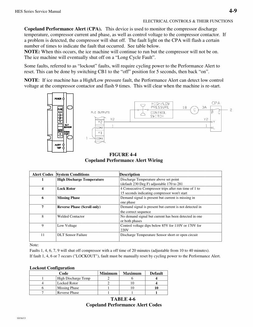
Copeland Performance Alert (CPA). This device is used to monitor the compressor discharge
temperature, compressor current and phase, as well as control voltage to the compressor contactor. If
a problem is detected, the compressor will shut off. The fault light on the CPA will flash a certain
number of times to indicate the fault that occurred. See table below.
NOTE: When this occurs, the ice machine will continue to run but the compressor will not be on.
The ice machine will eventually shut off on a “Long Cycle Fault”.
Some faults, referred to as “lockout” faults, will require cycling power to the Performance Alert to
reset. This can be done by switching CB1 to the “off” position for 5 seconds, then back “on”.
NOTE: If ice machine has a High/Low pressure fault, the Performance Alert can detect low control
voltage at the compressor contactor and flash 9 times. This will clear when the machine is re-start.
FIGURE 4-4 Copeland Performance Alert Wiring
Alert Codes System Conditions Description 1 High Discharge Temperature Discharge Temperature above set point
(default 230 Deg F) adjustable 170 to 281
4 Lock Rotor 4 Consecutive Compressor trips after run time of 1 to
15 seconds indicating compressor won't start
6 Missing Phase Demand signal is present but current is missing in
one phase
7 Reverse Phase (Scroll only) Demand signal is present but current is not detected in
the correct sequence
8 Welded Contactor No demand signal but current has been detected in one
or both phases
9 Low Voltage Control voltage dips below 85V for 110V or 170V for
220V
11 DLT Sensor Failure Discharge Temperature Sensor short or open circuit
Note:
Faults 1, 4, 6, 7, 9 will shut off compressor with a off time of 20 minutes (adjustable from 10 to 40 minutes).
If fault 1, 4, 6 or 7 occurs ("LOCKOUT"), fault must be manually reset by cycling power to the Performance Alert.
Lockout Configuration
Code Minimum Maximum Default 1 High Discharge Temp 2 6 4
4 Locked Rotor 2 10 4
6 Missing Phase 1 10 10
7 Reverse Phase 1 1 1
TABLE 4-6 Copeland Performance Alert Codes

4-10 HES Series Service Manual
ELECTRICAL CONTROLS & THEIR FUNCTIONS
5/24/11
Note: While in the Fault Mode, if Harvest / Start Button is pressed twice and the machine does not start, one of the following is true:* Bin control is not calling for ice or Selector switch is in the “off” position (PLC input lights 0 & 1 are “off”)
* The high / low pressure switch is tripped (PLC input light 6 is “off”)
* The Cutter or Pump overload is tripped (PLC input light 5 is “off”)
1 Flash - High / Low Pressure Fault during Freeze
2 Flashes - High / Low Pressure Fault during Harvest
3 Flashes - High / Low Pressure Fault during Partial Pumpdown
4 Flashes - High / Low Pressure Fault during Total Pumpdown
5 Flashes - Short Cycle Faults (3 Consecutive)
6 Flashes - Long Cycle Fault
7 Flashes - Water Pump Motor Overload Fault (3 Consecutive)
Freeze
Mode
Harvest
Mode
2 Minute
Freeze
Press Harvest / Start
Button twice to
restart machine
8 Flashes - Cutter Motor Overload Fault (3 Consecutive) Freeze
Mode
Harvest
Mode
2 Minute
Freeze
Run water
pump for
30 Minutes
Press Harvest / Start
Button twice to
restart machine
FIGURE 4-5
Machine Fault Startup Sequence
FIGURE 4-6
Fault Indicator / Selector Switch Location

HES Series Service Manual 4-11
ELECTRICAL CONTROLS & THEIR FUNCTIONS
10/16/13
FIGURE 4-7 Dual Ice Type (200/208/230V)
NOTE: USE COPPER CONDUCTORS RATED 60 °C OR HIGHER

4-12 HES Series Service Manual
ELECTRICAL CONTROLS & THEIR FUNCTIONS
10/16/13
FIGURE 4-8 Single Ice Type (200/208/230V)
NOTE: USE COPPER CONDUCTORS RATED 60 °C OR HIGHER

HES Series Service Manual 4-13
ELECTRICAL CONTROLS & THEIR FUNCTIONS
10/16/13
FIGURE 4-9 Dual Ice Type (400/460V)
NOTE: USE COPPER CONDUCTORS RATED 60 °C OR HIGHER

4-14 HES Series Service Manual
ELECTRICAL CONTROLS & THEIR FUNCTIONS
10/16/13
FIGURE 4-10 Single Ice Type(400/460V)
NOTE: USE COPPER CONDUCTORS RATED 60 °C OR HIGHER

HES Series Service Manual 4-15
ELECTRICAL CONTROLS & THEIR FUNCTIONS
5/24/11
Wiring Connections to Air-Cooled Condenser.
FIGURE 4-11 Wiring For BOHN DVT005 with Cold Weather Valve and Single Fan,
50/50 Condenser Split

4-16 HES Series Service Manual
ELECTRICAL CONTROLS & THEIR FUNCTIONS
5/24/11
FIGURE 4-12 Wiring For BOHN DVT008 with Cold Weather Valve and Single Fan,
50/25/25 Condenser Split

HES Series Service Manual 4-17
ELECTRICAL CONTROLS & THEIR FUNCTIONS
5/24/11
FIGURE 4-13 Wiring For BOHN DVT012 /DVT016 with Cold Weather Valve and Two Fan,
50/50 Condenser Split

5/24/11
Blank page


HES Series Service Manual
MAINTENANCE
10/16/2013
5-7
Part II. The inside of the water end plates and the outer tube sheet surfaces should be cleaned only with clear
water and a rag or a soft bristle brush. A worn paintbrush is excellent. These surfaces have been
coated with a special material, which will give years of protection against corrosion unless damaged.
Never use a wire brush or a strong caustic on these surfaces.
Flush condenser tubes clear with air, water, or a piece of rag on a stick or wire. In many cases this is
all that is required. If the inside surfaces are smooth, even though discolored, further cleaning is not
necessary. It is useless to try and get a bright copper surface on the inside of the tubes. They will
discolor almost immediately in service and the condenser has been designed with an adequate
reserve for moderate fouling on these surfaces.
If, however, a rough coating remains inside the tubes after flushing and wiping, further cleaning is
desirable. The color of this coating varies with water conditions, but roughness indicates cleaning
tools should be used.
Any type tool to be considered should be tried first on a piece of copper tubing held in a vise or flare
block. Nylon, brass, or copper brushes are recommended. If any flakes of copper appear or if score
marks are made inside the tube, the tool should not be used. Never use anything with sharp or rigid
edges, which could cut into the copper tubing.
A cleaning tool is available from Vogt
through your distributor. Part #12A 2055B01.
When using a cleaning tool, keep the inside of the tube wet and move the tool slowly from one end
to the other while rotating it at a moderate speed. A hand drill brace is recommended. If an electric
drill is used, a low speed attachment on a 1/4” size drill is preferred. Larger units are powerful
enough to damage a tube, if for any reason, the cleaning tool should stick. After one or two passes
in each tube, they should be flushed and inspected. Often this is enough, although some deposits
require more. In any case, stop when a few places begin to show a copper color.
After cleaning, wipe all foreign matter from the tube sheets and studs. Reassemble as outlined on
gasket installation instructions.
If the gasket seal ridge was damaged and a replacement is not immediately available, water leaks can
be stopped by removing the gasket, drying it, and apply a thin film of a non-hardening gasket sealer,
such as Permatex #2, around the seal ridge. This film should be no thicker than the height of the
ridge itself and about 3/16” wide. Then re-assemble.
If a new gasket is put on later, be sure to remove any grit or particles that stick to the sealer film on
the tube sheet. It is not necessary to remove all traces of the sealer before installing a new gasket, as
long as no particles that cut into the new gasket remain on the surface.
Water Cooled Condenser Gasket Machine Manufacture Model # Vogt Part # Vogt Part #
HES-20 KH-2X 12A2115S0401 12A2600S01
HES-30 KH-3X or C-3X 12A2115S0301 12A2600S01
HES-40 KH-5X or C-5X 12A2115S0201 12A2600S03
TABLE 5-2 Water Cooled Condenser Gasket

HES Series Service Manual
MAINTENANCE
10/16/2013
5-8
Air-Cooled Condenser Cleaning. Visual inspection will indicate if dirt is accumulating and
clogging the fin face of the condenser. A vacuum cleaner, compressed air, or a brush may be used to
remove any accumulation of loose dirt from the fin section of the condenser.
For the removal of more severe accumulations of dirt or foreign materials, a detergent-type cleaner
can be used. Your local refrigeration supply house can supply this cleaning agent. Follow the
manufacturer’s instructions when using a liquid cleaner.
If fins have been damaged, they should be straightened with the proper fin comb.
Compressor Oil. In starting and charging the unit, the oil sight glass (33) in the crankcase of the
compressor should be watched carefully for the first hour to make certain the proper lubrication is
being maintained. The oil may become low in the crankcase on an initial start-up if the electrical
current has been interrupted to the machine, thus de-energizing the compressor crankcase heater.
Before starting the machine again, the heater should be energized for a time period of at least two
hours to evaporate refrigerant that may have condensed in the crankcase during the shutdown period.
If level is low after start-up, it should begin to return after a short period of operation.
The oil level should be checked frequently, particularly during the start-up operation, to see that a
sufficient amount of oil remains in the crankcase. While it is important to observe the oil splash
during operation, the true level can be obtained only when the compressor is stopped. With the
compressor idle, the oil level should be between 1/2 to 3/4 of the sight glass, but not above the top of
the sightglass.
Although the machine was shipped with the oil charge, which was originally added for the test
operation, it may be necessary to add some oil when or if new refrigerant is added to the system.
An oil pump should be used to force any oil that may be required into the system. Oil may be added
to the compressor of all units through the compressor oil charging port. Air should be purged from
the oil pump discharge line by forcing some oil through the line before tightening the charging port.
R22 – use “Dual Inhibited Sunisco 3GS” (Viscosity 150) or equal.
R404A – use Polyolester (POE) Oil (Viscosity 150).
FIGURE 5-2 Scroll Compressor
Cutter Gear Reducer Oil. The oil level for the gear reducer should be checked if there is evidence
of a leak. It should be level with the plugged opening in the side of the gear housing. Use Mobile
600W cylinder oil or equal.

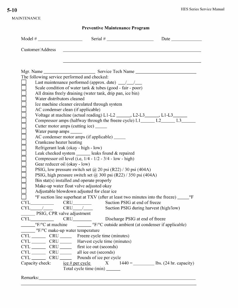

HES Series Service Manual
TROUBLESHOOTING
3/25/08
6-1
6. Troubleshooting
The HES Series is equipped with a PLC (programmable logic controller) that controls all aspects of the machines operation. One function of the PLC is to shut down the machine when a machine fault occurs. By continuously monitoring the High / Low pressure safety switch, the Freeze cycle time, and the cutter and pump motor overloads, the PLC can determine if a problem exist. There are two types of faults, which can occur: an "auto-restart fault" and a "major fault". For your reference, TABLE 6-1 contains a list of fault codes.
"Auto-Restart Fault" - if the machine shuts off due to a "short cycle" fault, a pump motor overload or a cutter motor overload, the machine will automatically restart itself after a predetermined amount of time (Off Delay). If an auto-restart fault occurs three consecutive times, it will be considered a "major" fault and not automatically restart.
"Major Fault" - if the machine shuts off due to a High / Low Pressure fault or a "long cycle" fault, the machine will not automatically restart. This is considered a "major" fault. Note: A major fault is also an auto-restart fault that has occurred three consecutive times. When a "major fault" occurs, the PLC sends a signal to the fault indicator light located on the far-left side of the electrical panel. The red light is visible through the opening in the front casing and will display the appropriate error code (See FIGURE 6-2). NOTE: The Fault Light will flash the designated number of times ONLY if the fault is a "major fault". The machine may be off on a fault and not flashing an error code if the fault is an auto-restart fault and it is not the third consecutive occurrence of this fault.
# Description Auto-Restart Off Delay
1 High / Low Press - Freeze No N/A 2 High / Low Press - Harvest No N/A 3 High / Low Press - Partial Pump down No N/A 4 High / Low Press - Total Pump down No N/A 5 Short Cycle Yes 2 hrs 6 Long Cycle No N/A 7 Pump Motor Overload Yes 30 min 8 Cutter Motor Overload Yes 30 min
N/A Power Failure Yes 2 hrs TABLE 6-1
PLC Fault Codes NOTE: If Auto-Restart = No, fault is considered a "major fault"

HES Series Service Manual
TROUBLESHOOTING
3/25/08
6-2
FIGURE 6-1
Machine Fault Indicator Light
Note: While in the Fault Mode, if Harvest / Start Button is pressed twice and the machine does not start, one of the following is true:* Bin control is not calling for ice or Selector switch is in the “off” position (PLC input lights 0 & 1 are “off”)* The high / low pressure switch is tripped (PLC input light 6 is “off”)
* The Cutter or Pump overload is tripped (PLC input light 5 is “off”)
1 Flash - High / Low Pressure Fault during Freeze
2 Flashes - High / Low Pressure Fault during Harvest
3 Flashes - High / Low Pressure Fault during Partial Pumpdown
4 Flashes - High / Low Pressure Fault during Total Pumpdown
5 Flashes - Short Cycle Faults (3 Consecutive)
6 Flashes - Long Cycle Fault
7 Flashes - Water Pump Motor Overload Fault (3 Consecutive)
FreezeMode
HarvestMode
2 MinuteFreeze
Press Harvest / StartButton twice torestart machine
8 Flashes - Cutter Motor Overload Fault (3 Consecutive) FreezeMode
HarvestMode
2 MinuteFreeze
Run waterpump for
30 Minutes
Press Harvest / StartButton twice torestart machine
FIGURE 6-2 Machine Major Fault Startup Sequence

HES Series Service Manual
TROUBLESHOOTING
3/25/08
6-3
Harvest Timer adjustment
Programming Port
Output Indicator Lights
Input Indicator Lights
PLC Program Run / Stop switch
PLC Error Light
FXos
FXo
MITSUBISHI
MELSEC FX OS -14MR-ES
Harvest Timer adjustment
Programming Port
PLC Error Light
Output Indicator Lights
Input Indicator Lights
Harvest Timer adjustment (top screw)
Programming Port Output Indicator Lights
Input Indicator Lights
PLC Program Run / Stop switch
PLC Error Light
FX1s
PLC Program Run / Stop switch
FIGURE 6-3 PLC (Programmable Logic Controller)
PLC Inputs PLC Outputs # Description # Description 0 Cylinder Ice Indicator 0 Machine Fault Indicator Light 1 Crushed Ice Indicator 1 "A" valve 2 Freezer Pressure Switch 2 Compressor 3 Start / Manual Harvest 3 Reversing Relay (Dual Ice only) 4 Clean Switch 4 Water Pump 5 Pump / Cutter Overload (“off” when tripped) 5 Cutter / "D" valve / Suction Stop 6 High / Low Pressure safety (“off” when tripped) 7 Oil Level Safety (Optional)
TABLE 6-2 PLC Inputs & Outputs
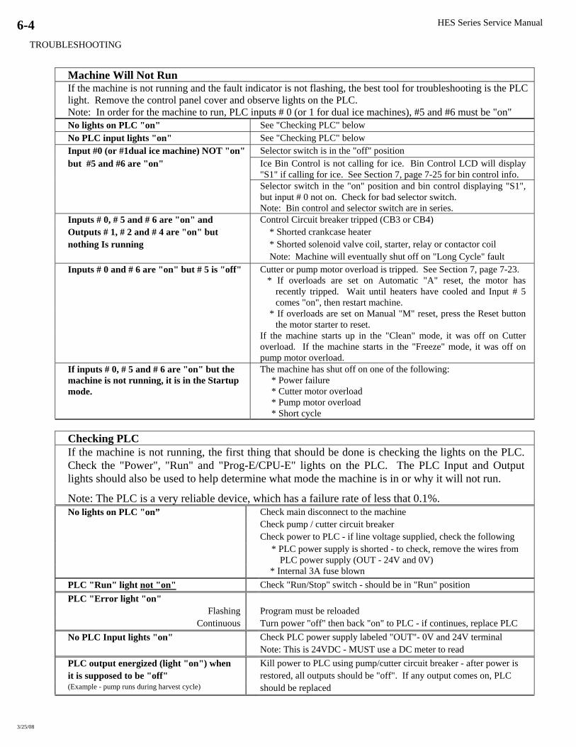
HES Series Service Manual
TROUBLESHOOTING
3/25/08
6-4
Machine Will Not Run If the machine is not running and the fault indicator is not flashing, the best tool for troubleshooting is the PLC light. Remove the control panel cover and observe lights on the PLC. Note: In order for the machine to run, PLC inputs # 0 (or 1 for dual ice machines), #5 and #6 must be "on" No lights on PLC "on" See "Checking PLC" below No PLC input lights "on" See "Checking PLC" below Input #0 (or #1dual ice machine) NOT "on" Selector switch is in the "off" position but #5 and #6 are "on" Ice Bin Control is not calling for ice. Bin Control LCD will display
"S1" if calling for ice. See Section 7, page 7-25 for bin control info. Selector switch in the "on" position and bin control displaying "S1",
but input # 0 not on. Check for bad selector switch. Note: Bin control and selector switch are in series.
Inputs # 0, # 5 and # 6 are "on" and Control Circuit breaker tripped (CB3 or CB4) Outputs # 1, # 2 and # 4 are "on" but * Shorted crankcase heater nothing Is running * Shorted solenoid valve coil, starter, relay or contactor coil Note: Machine will eventually shut off on "Long Cycle" fault Inputs # 0 and # 6 are "on" but # 5 is "off" Cutter or pump motor overload is tripped. See Section 7, page 7-23.
* If overloads are set on Automatic "A" reset, the motor has recently tripped. Wait until heaters have cooled and Input # 5 comes "on", then restart machine.
* If overloads are set on Manual "M" reset, press the Reset button the motor starter to reset.
If the machine starts up in the "Clean" mode, it was off on Cutter overload. If the machine starts in the "Freeze" mode, it was off on pump motor overload.
If inputs # 0, # 5 and # 6 are "on" but the machine is not running, it is in the Startup mode.
The machine has shut off on one of the following: * Power failure * Cutter motor overload * Pump motor overload * Short cycle
Checking PLC If the machine is not running, the first thing that should be done is checking the lights on the PLC. Check the "Power", "Run" and "Prog-E/CPU-E" lights on the PLC. The PLC Input and Output lights should also be used to help determine what mode the machine is in or why it will not run.
Note: The PLC is a very reliable device, which has a failure rate of less that 0.1%. No lights on PLC "on” Check main disconnect to the machine
Check pump / cutter circuit breaker Check power to PLC - if line voltage supplied, check the following
* PLC power supply is shorted - to check, remove the wires from PLC power supply (OUT - 24V and 0V)
* Internal 3A fuse blown PLC "Run" light not "on" Check "Run/Stop" switch - should be in "Run" position PLC "Error light "on"
Flashing Program must be reloaded Continuous Turn power "off" then back "on" to PLC - if continues, replace PLC
No PLC Input lights "on" Check PLC power supply labeled "OUT"- 0V and 24V terminal Note: This is 24VDC - MUST use a DC meter to read
PLC output energized (light "on") when Kill power to PLC using pump/cutter circuit breaker - after power is it is supposed to be "off" restored, all outputs should be "off". If any output comes on, PLC (Example - pump runs during harvest cycle) should be replaced

HES Series Service Manual
TROUBLESHOOTING
3/25/08
6-5
Low Ice Capacity If the machine is operating but appears low on capacity, check the following: Determine the machines actual capacity by obtaining the following information: makeup water temperature, freeze cycle times, harvest time, and amount of ice per cycle.
Capacity (lbs/day) = 1440 (min/day) / Total cycle (min) * Ice (lbs). See Section 9 for machines rated capacity and operating vitals.
Intermittent power interruptions or power failure.
If there is a power failure or a power interruption, the machine will advance to a start-up mode when power is restored. After a two-hour period, the machine will restart automatically if there is no other problem.
Cutter or pump motor overload trips (PLC input # 5 light "off")
If the cutter or pump motor overloads trip, the machine will shut off and go to the start-up mode. Because the overload resets are set on automatic, "A", when the overload heater packs cool, they will reset. After a 30 minute delay the machine will restart. If you suspect this is a problem, set the overloads resets on manual, "M". See Section 7, page 7-23.
Electronic Bin Control not positioned correctly or properly set, shutting machine off prematurely
See that bin control is positioned correctly and set properly.
Extended Freeze times Certain mechanical problems can cause the machine to run extended freeze cycles. These long freeze cycles may not be long enough to cause the machine to shut off on "long cycle" fault, but long enough to reduce capacity substantially.
* Hot water being supplied to the machine for making ice * High Compressor discharge pressure * Improperly set or defective water float valve
* Leaking or open water tank drain valve * Faulty D-valve (not closing properly) Machine Short Cycles If machine is "short cycling" due to a mechanical or electrical
problem, the machine will shut off and advance to a start-up mode. After a two-hour period, the machine will restart automatically. (See Fault # 5 for possible causes)

HES Series Service Manual
TROUBLESHOOTING
3/25/08
6-6
Major Fault - Below is a list of the Major Faults and possible causes.
Fault # 1 - High / Low Compressor Pressure - Freeze Mode (Fault Indicator Light Flashing One Time) This fault can be caused by either high compressor discharge pressure or low compressor suction pressure. This fault is sensed by the compressor's High/Low Pressure safety switch (PLC input - X6). During normal machine operation, this safety switch is closed and PLC input X6 is "ON". When this fault occurs, the safety switch opens and X6 turns "OFF". - With a Low pressure fault, the safety switch will automatically reset (input # 6 will come "on") when
compressor suction pressure comes up to the set-point (40 PSI). - With High-pressure fault, the safety switch must be manually reset.
Note: Discharge pressure must be 50 psig below the set point of the switch. This switch is sometimes very hard to reset. Low Suction Pressure Broken or leaking capillary tube going from freezer to harvest
pressure switches Rota-lock valve on bottom of freezer is backseated, shutting off freezer pressure switch Faulty or improperly adjusted cylinder ice harvest pressure switch Note: If crushed ice harvest pressure switch is bad or improperly
adjusted, cylinder ice harvest pressure switch would eventually close causing machine to harvest. If this occurs, ice would be thick and could possibly cause the cutter overload to trip.
Faulty PLC input - X2 (will not sense voltage) Suction stop valve stuck closed (valve is normally on) Closed compressor suction valve
High Discharge Pressure Dirty condenser restricting air or water flow Restriction in condenser return line Closed compressor discharge valve Water cooled only
* Faulty or improperly adjusted condenser water regulator valve * No condenser water
Air cooled only * Faulty X-Valve or X-Valve coil * Faulty condenser fan motor * Faulty condenser fan contact * Faulty condenser fan control pressure switch
Other Problems Faulty PLC input - X6 (will not sense input voltage) (Not High or Low Pressure) Broken or leaking capillary tube going from compressor to low side of
High / Low Pressure safety switch Faulty or improperly adjusted High / Low Pressure safety switch
HES Series Service Manual
TROUBLESHOOTING
3/25/08
6-7
Fault # 2 - High / Low Compressor Pressure - Harvest Mode (Fault Indicator Light Flashing 2 Times) This fault can be caused by either high compressor discharge pressure or low compressor suction pressure. This fault is sensed by the compressor's High/Low Pressure safety switch (PLC input - X6). During normal machine operation, this safety switch is closed and PLC input X6 is "ON". When this fault occurs, the safety switch opens and X6 turns "OFF". - With a Low pressure fault, the safety switch will automatically reset (input # 6 will come "on") when
compressor suction pressure comes up to the set-point (40 PSI). - With High-pressure fault, the safety switch must be manually reset.
Note: Discharge pressure must be 50 psig below the set point of the switch. This switch is sometimes very hard to reset. Low Suction Pressure Faulty D-Valve or D-Valve coil (not opening properly)
Note: A faulty D-Valve or D-Valve coil may also cause the machine to stay in a continuos harvest, causing a short cycle fault.
High Discharge Pressure Faulty X-Valve or X-Valve coil (Air cooled only) Dirty condenser restricting air or water flow Restriction in condenser return line
Other Problems Faulty PLC input - X6 (will not sense input voltage) (Not High or Low Pressure) Broken or leaking capillary tube going from compressor to low side
of High / Low Pressure safety switch Faulty or improperly adjusted High / Low Pressure safety switch
Fault # 3 - High / Low Compressor Pressure - Partial Pump down Mode (Fault Indicator Light Flashing 3 Times) This fault can be caused by either high compressor discharge pressure or low compressor suction pressure. This fault is sensed by the compressor's High/Low Pressure safety switch (PLC input - X6). During normal machine operation, this safety switch is closed and PLC input X6 is "ON". When this fault occurs, the safety switch opens and X6 turns "OFF". - With a Low-pressure fault, the safety switch will automatically reset (input # 6 will come "on") when
compressor suction pressure comes up to the set-point (40 PSI). - With High-pressure fault, the safety switch must be manually reset.
Note: Discharge pressure must be 50 psig below the set point of the switch. This switch is sometimes very hard to reset. Low Suction Pressure Low refrigerant charge which allows the compressor to pull freezer
pressure down Faulty A-Valve or A-Valve coil (not opening properly)
High Discharge Pressure Dirty condenser restricting air or water flow Restriction in condenser return line Closed compressor discharge valve
Water cooled only * Faulty or improperly adjusted condenser water regulator valve * No condenser water Air cooled only * Faulty X-Valve or X-Valve coil * Faulty condenser fan motor * Faulty condenser pressure switch (CPS)
* Faulty condenser fan control pressure switch Other Problems Faulty PLC input - X6 (will not sense input voltage) (Not High or Low Pressure) Broken or leaking capillary tube going from compressor to low side
of High / Low Pressure safety switch Faulty or improperly adjusted High / Low Pressure safety switch
HES Series Service Manual
TROUBLESHOOTING
3/25/08
6-8
Fault # 4 - High / Low Compressor Pressure - Total Pumpdown Mode (Fault Indicator Light Flashing 4 Times)
This fault can be caused by either high compressor discharge pressure or low compressor suction pressure. This fault is sensed by the compressor's High/Low Pressure safety switch (PLC input - X6). During normal machine operation, this safety switch is closed and PLC input X6 is "ON". In this mode the Low Pressure safety switch is used to indicate that the freezer is pumped down and for the machine to leave the Total Pump down Mode. At this time input X6 will be "OFF". Because of this, the controller will not determine a low-pressure fault until the machine attempts to go to the Freeze Mode. (This will actually occur while machine is in the Standby Mode). If the machine is unable to reset the High / Low Pressure safety switch by raising the freezer pressure, or unable to raise the freezer pressure itself, the controller will sense a problem and set the fault. With High pressure fault, the safety switch must be manually reset. Low Suction Pressure Faulty A-Valve or A-Valve coil (not opening properly) Note: If this occurs, the machine may be unable to raise the freezer
pressure above the set-point (35 PSI) to reset the High / Low Pressure safety switch.
High Discharge Pressure Dirty condenser restricting air or water flow Restriction in condenser return line Closed compressor discharge valve
Water cooled only * Faulty or improperly adjusted condenser water regulator valve * No condenser water Air cooled only * Faulty X-Valve or X-Valve coil * Faulty condenser fan motor * Faulty condenser fan contact
* Faulty condenser fan control pressure switch Other Problems Faulty PLC input - X6 (will not sense input voltage) (Not High or Low Pressure) Broken or leaking capillary tube going from compressor to low side
of High / Low Pressure safety switch. Faulty or improperly adjusted High / Low Pressure safety switch Faulty or improperly adjusted cylinder ice harvest pressure switch. Note: If harvest pressure switch is not closed when High / Low Pressure safety switch opens, the controller will think there is a problem with the compressor operating pressure and set the fault. * Make sure the differential on the cylinder ice harvest pressure
switch is set correctly (10 PSI) as well as the low pressure cut-in differential on the High / Low Pressure Safety Switch (20 PSI).

HES Series Service Manual
TROUBLESHOOTING
3/25/08
6-9
Fault # 5 - Short Cycle Fault (Fault Indicator Light Flashing 5 Times) A "short cycle" is defined as a Freeze cycle which is less than a predetermined amount of time: HES-20 = 10 minutes HES-30 = 5 minutes HES-40 = 5 minutes If machine runs three consecutive short cycles, it will shut down on Short cycle fault. After a 2 hour delay, the machine will restart in the Harvest mode before going to a Freeze cycle. If the machine does not finish a full freeze (short cycle timer times out) the machine will shut off on a Short cycle fault again. If this occurs again, the machine will shut off and not restart itself. This fault occurs when the machine encounters three (3) short cycle faults in a row.
Reduced heat load on the Freezer * Clogged or partially obstructed water distributors * Pump not supplying adequate water flow (dirty or defective) * Improper or No makeup water flow Low refrigerant level in freezer * Low refrigerant charge in machine
* Faulty A-Valve or A-Valve coil (not opening properly) * Clogged filter drier * Restriction in the liquid line (TXV strainer)
* Improperly adjusted or defective TXV Faulty or improperly adjusted harvest pressure switch
Freezer full of ice (refreeze-not all ice getting out during harvest) * Low compressor discharge pressure * Faulty D-Valve or D-Valve coil (not opening properly)
* Harvest cycle too short * Not enough heat to get ice out during harvest - Condenser fan motor (s) running continuously - Sub cooled liquid return from condenser - Restriction in condenser liquid return line Non-Condensables in system
Fault # 6 - Long Cycle Fault (Fault Indicator Light Flashing 6 Times) A "long cycle" occurs when the machine is in the Freeze Mode for a predetermined amount of time and has not made a batch of ice. Long Freeze cycle times are defined as: HES-20 = 120 minutes HES-30 = 80 minutes HES-40 = 60 minutes Leaking or open water tank drain valve Improperly set or defective water float valve (on continually)
Faulty D-Valve (not closing properly) Damaged compressor
Compressor not running * Compressor Thermal overload * Faulty compressor contactor
Control Circuit breaker tripped (CB3 or CB4) * Shorted crankcase heater * Shorted solenoid valve coil, starter, relay or contactor coil

HES Series Service Manual
TROUBLESHOOTING
3/25/08
6-10
Fault # 7 - Pump Motor Overload Fault (Fault Indicator Light Flashing 7 Times) A three phase motor starter with adjustable bimettalic heater packs, wired for use on single phase, controls the water pump motor. The overloads are configured to reset automatically (“A”) after a overload condition occurs. When this occurs auxiliary contact signals the PLC of a problem and shuts the machine off (PLC input light # 5 will be “off” when overload is tripped). Will automatically reset after an overloads cool. Pull the reset button to test the overload. This fault occurs when the water pump overload has tripped 3 consecutive cycles. Low voltage being supplied to pump motor *Low voltage supplied to machine
*Loose wire on the motor starter * Voltage drop across motor starter contacts
Overloads heaters set too low - See Section 7, Table 7-11 Start switch on pump motor sticking Running water pump dry
Defective pump motor
Fault # 8 - Cutter Motor Overload Fault (Fault Indicator Light Flashing 8 Times) A three phase motor starter with adjustable bimettalic heater packs, wired for use on single phase, controls the cutter motor. The overloads are configured to reset automatically (“A”) after a overload condition occurs. When this occurs auxiliary contact signals the PLC of a problem and shuts the machine off (PLC input light # 5 will be “off” when overload is tripped). Will automatically reset after an overloads cool. Pull the reset button to test the overload. This fault occurs when the cutter motor overload has tripped 3 consecutive cycles. Low voltage being supplied to cutter motor *Low voltage supplied to machine
*Loose wire on the cutter motor starter * Voltage drop across motor starter contacts
Overloads set too low - See Section 7, Table 7-11 Ice backing up into ice chute
* Bin stat mounted incorrectly / set incorrectly / defective * Deflector door not switching properly
(Dual ice machines only) Making solid ice / freezer full of ice (Refreeze-not all ice getting out during harvest)
* Faulty or improperly adjusted harvest pressure switch * Low compressor discharge pressure * Faulty D-Valve or D-Valve coil (not opening properly) * Harvest cycle too short
Defective cutter motor Defective gear reducer

HES Series Service Manual
SERVICE OPERATIONS
3/25/08
7-1
7. Service Operations
FIGURE 7-1A
Front View
FIGURE 7-1B Side View

HES Series Service Manual
SERVICE OPERATIONS
3/25/08
7-2
FIGURE 7-1C Rear View (Water Cooled)
FIGURE 7-1D Rear View (Air Cooled)
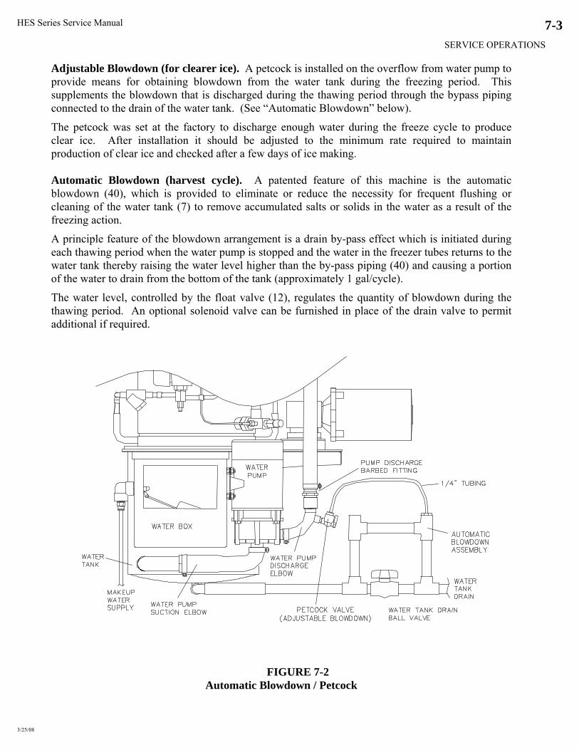
HES Series Service Manual
SERVICE OPERATIONS
3/25/08
7-3
Adjustable Blowdown (for clearer ice). A petcock is installed on the overflow from water pump to provide means for obtaining blowdown from the water tank during the freezing period. This supplements the blowdown that is discharged during the thawing period through the bypass piping connected to the drain of the water tank. (See “Automatic Blowdown” below).
The petcock was set at the factory to discharge enough water during the freeze cycle to produce clear ice. After installation it should be adjusted to the minimum rate required to maintain production of clear ice and checked after a few days of ice making. Automatic Blowdown (harvest cycle). A patented feature of this machine is the automatic blowdown (40), which is provided to eliminate or reduce the necessity for frequent flushing or cleaning of the water tank (7) to remove accumulated salts or solids in the water as a result of the freezing action.
A principle feature of the blowdown arrangement is a drain by-pass effect which is initiated during each thawing period when the water pump is stopped and the water in the freezer tubes returns to the water tank thereby raising the water level higher than the by-pass piping (40) and causing a portion of the water to drain from the bottom of the tank (approximately 1 gal/cycle).
The water level, controlled by the float valve (12), regulates the quantity of blowdown during the thawing period. An optional solenoid valve can be furnished in place of the drain valve to permit additional if required.
FIGURE 7-2 Automatic Blowdown / Petcock

HES Series Service Manual
SERVICE OPERATIONS
3/25/08
7-4
Float Valve (make-up water). The make-up water float valve (12) maintains the proper pumping level in the water tank for ice making. The valve should be set to maintain a water level in the water tank during the freezing period, so that there will be a quantity of by-pass or blowdown only during the thaw mode. The water level during the freeze mode should always be below the by-pass piping to prevent excessive waste of cold water, resulting in loss of ice capacity.
If it should become necessary to clean the float valve, close the stop valve in the make-up water line to the machine and remove the float valve. After the valve has been cleaned and reinstalled, check to ascertain if the proper water level is being maintained.
It is advisable to install a large area strainer in the water supply line to protect the float valve from dirt or solids in the water, which would necessitate frequent cleaning. A strainer of 40-mesh screen is usually satisfactory.
FIGURE 7-3 Water Float Valve
Circulating Water Pump Motor. The motor bearings are pre-lubricated and sealed. They require no further lubrication. Pump should operate with the water level above the impeller housing.
The pump is equipped with a mechanical seal, which is self-addressing and requires no lubrication. However, the pump should not be operated unless circulating water. The pump manufacturer recommends that a mechanical seal be kept as a spare. When ordering replacement parts, specify pump size, type, serial number, and manufacturer’s name as indicated on the nameplate.
FIGURE 7-4 Circulating Water Pumps
Vogt Part #: 12A4200H0401
Vogt Part #: 12A2450E29
Water Pump Suction Elbow
Water Pump Discharge Elbow
Vogt Part #: 12A2450E30
Water Pump Suction
Water Pump Discharge
American Products Pump (AP) Gorman Rupp Pump (GRI)

HES Series Service Manual
SERVICE OPERATIONS
3/25/08
7-5
Vogt Part #’s Description Frequency Pump/Motor # Impellor # Seal # “O” Ring #
AP Pump 60hz 12A4020A06 12A4020Y02 12A4080S04 126628AP 50hz 12A4020A07 12A4020Y04 12A4080S04 126628AP
GRI Pump 60hz 12A4020GR01 12A4080S21 50hz 12A4020GR02 12A4080S22
TABLE 7-1 Water Pump Part #’s
Water Distributors. The water distributors are located in the distributing head (8) at the top of the freezer. There are 78 distributors used in models having an “S” suffix (i.e., Models HES-10S, HES-20S, HES-30S, and HES-40S); 48 distributors are used in models having an “M” suffix (i.e., Models HES-10M, HES-20M, HES-30M, and HES-40M). These may require occasional or periodical cleaning to remove suspended solids and foreign particles accumulated from the make-up water. The frequency of this cleaning operation will depend on the characteristics of the water supply.
The cleaning operation is indicated when the inside diameter of a large proportion of the ice becomes irregular (due to channeling of the water) or if some of the ice is opaque. Or if there is a noticeable decrease in ice capacity.
To clean distributors, stop the unit and remove the freezer cover (8) on top of the freezer. The water distributors may then be removed with pliers for cleaning by soaking in a solution of ice machine cleaner or 10% muratic acid and water. Grasp the top of the distributor gently with pliers, twist, and pull up and out of the tube. After cleaning, reinstall distributors firmly in each tube.
Note: When re-installing distributors on the outside row, make sure holes are away from the gasket
Vogt Part # Size Ice Number of Tubes Water Distributor Freezer Cover Freezer Cover Gasket
1” 78 12B2185N11 1 1/4” 48 12B2185N21
12A2145C09 12A2600G01
TABLE 7-2 Water Distributor / Freezer Cover / Gasket Part #’s
Freezer Cover
Water Distributors
Freezer Cover Gasket
FIGURE 7-5 Freezer Cover / Gasket / Water Distributors
! WARNING !
Acid can cause serious burns or blindness. Always add the acid to the water for dilution. Wear eye and body protection.
! WARNING !

HES Series Service Manual
SERVICE OPERATIONS
3/25/08
7-6
Water Tank. The production of opaque ice usually indicates that the water in the water tank contains a concentrated amount of solids or salts.
Remove cover plate, open drain valve (39) and clean tank thoroughly by flushing out with a hose and scrubbing with a stiff brush. Close the drain valve and refill tank with fresh water.
When restarting the machine after filling the water tank, be sure that the water pump is circulating water. It is possible that air may have collected in the pump impeller housing and the unit may have to be stopped and started several times to expel the air.
FIGURE 7-6
Cutter/Water Tank Assembly With Water Pump and Cutter Motor
Cutter Gear Reducer. The oil level for the gear reducer should be checked if there is evidence of a leak. It should be level with the plugged opening in the side of the gear housing. Use Mobile 600W cylinder oil or equal. (Replacement oil 19T3020C01)
The motor bearings are prelubricated and require no further lubrication.

HES Series Service Manual
SERVICE OPERATIONS
3/25/08
7-7
Gear Reducer Replacement.
1. Stop the machine and lockout its power.
2. Remove four cap screws holding the motor to the reducer housing.
3. Separate the motor from the reducer by pulling the motor and shaft out of the reducer sleeve. Be sure to catch and save shaft key for later reassembly.
4. Remove bolts holding gearbox-mounting plate to the drive gear enclosure and lift out gear reducer and plate assembly.
5. Remove drive gear from the reducer output shaft. Two 1/4”-20 x 1 1/2” long (all thread) bolts can be used for jacking screws in the two threaded holes of the drive gear.
6. Remove the split hub (bushing) from the reducer shaft and remove the gear reducer from the mounting plate.
7. Reassemble in the reverse order.
8. After assembly of the drive gear on the gear reducer, set the assembly in place in the enclosure, and check vertical alignment of the drive gear and cutter ring gear. Turn the gears by hand a full turn to make sure they engage the full width of the teeth. Adjust the hub accordingly.
9. Adjust the horizontal engagement of the gear teeth by the four bolts holding the reducer to the mounting. There should be only a slight amount of tooth clearance at the closest engagement spot.
10. After complete assembly, test operation and check for unusual noise and normal motor amperage. Cutter Bearing. The cutter bearing is of the sleeve type and is made of UHMW plastic requiring no lubrication. If necessary to replace this bearing, follow instructions under heading “Cutter and Gear Drive”. Cutter and Gear Drive. To remove the ice cutter (21), when and if necessary, proceed as follows:
1. Turn machine off.
2. Close the stop valve in the make-up water line to water pan.
3. Drain the tank, disconnect the make-up water line and drain line from the water tank.
4. Separate motor from the cutter drive reducer by removing four cap screws. Watch for shaft key when separating unit, which must be installed in motor keyway when unit is reassembled. It is not necessary to remove the reducer from its mounting plate on the water pan.
5. Remove the water pump, which is attached to the side of the tank by four bolts and nuts.
6. Remove ice discharge chute, which is attached to the water tank by four wing nuts.
7. Remove the water tank assembly which contains the cutter by removing four bolts and nuts from around the top edge of the tank.
Assembly may then be taken to a workbench for removal of cutter.
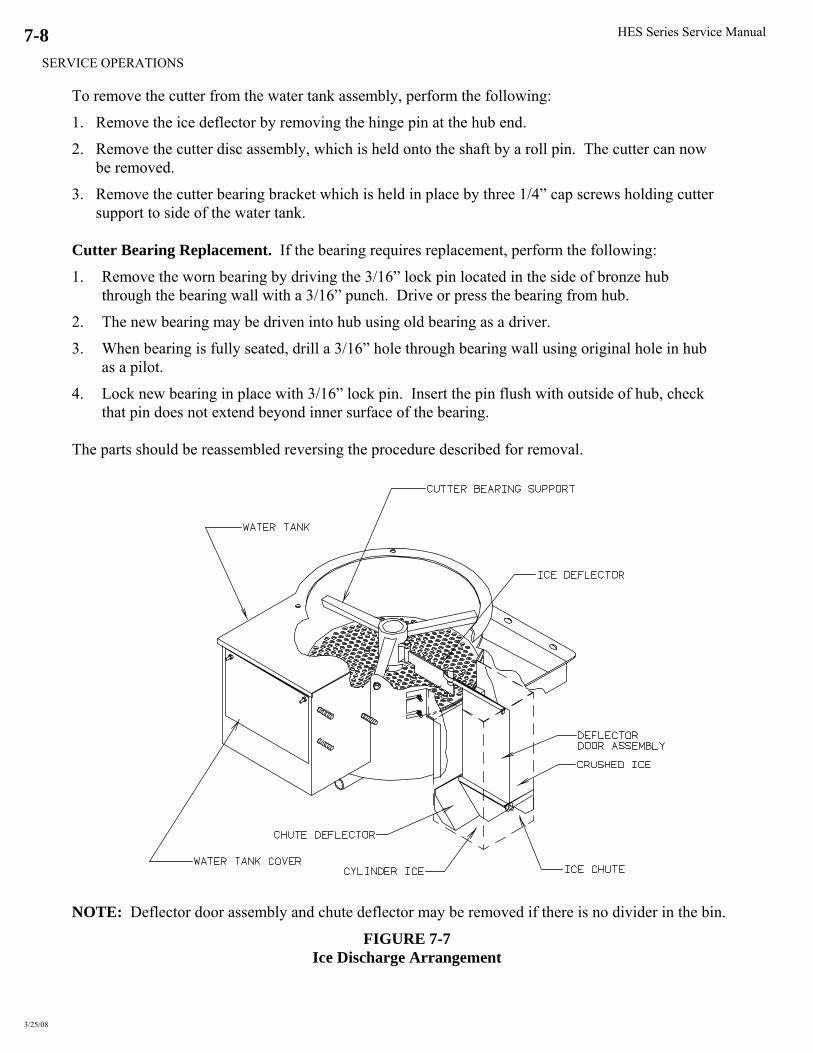
HES Series Service Manual
SERVICE OPERATIONS
3/25/08
7-8
To remove the cutter from the water tank assembly, perform the following:
1. Remove the ice deflector by removing the hinge pin at the hub end.
2. Remove the cutter disc assembly, which is held onto the shaft by a roll pin. The cutter can now be removed.
3. Remove the cutter bearing bracket which is held in place by three 1/4” cap screws holding cutter support to side of the water tank.
Cutter Bearing Replacement. If the bearing requires replacement, perform the following:
1. Remove the worn bearing by driving the 3/16” lock pin located in the side of bronze hub through the bearing wall with a 3/16” punch. Drive or press the bearing from hub.
2. The new bearing may be driven into hub using old bearing as a driver.
3. When bearing is fully seated, drill a 3/16” hole through bearing wall using original hole in hub as a pilot.
4. Lock new bearing in place with 3/16” lock pin. Insert the pin flush with outside of hub, check that pin does not extend beyond inner surface of the bearing. The parts should be reassembled reversing the procedure described for removal.
NOTE: Deflector door assembly and chute deflector may be removed if there is no divider in the bin.
FIGURE 7-7 Ice Discharge Arrangement

HES Series Service Manual
SERVICE OPERATIONS
3/25/08
7-9
12A2900M0507 1/2 HP 50/60HZ CUTTER MOTOR
19T4500S12 GEAR BOX MOUNTING PLATE ASSEMBLY (PART OF WATER TANK)
12A4030R12 GEAR REDUCER (10:1)
WATER PUMP HZ - 12A4020A06
50HZ – 12A4020A07 60
12A3040S01 STAINLESS STEEL SPIROL PIN 1/4” DIA X 1 1/2” LONG
WATER PUMP (GORMAN-RUPP) 60HZ – 12A4020GR01 50HZ – 12A4020GRO2
FIGURE 7-8 Cutter/Water Tank Parts

HES Series Service Manual
SERVICE OPERATIONS
3/25/08
7-10
12A2240A1108 HEX NUT 5/16” S S
12A4030R12 GEAR REDUCER (10:1)
FIGURE 7-9 Cutter Drive Parts

HES Series Service Manual
SERVICE OPERATIONS
3/25/08
7-11
12A3040S01 SS SPIROL PIN 1/4” DIA X 1 1/2” LONG (FOR CUTTER DISC)
FIGURE 7-10 Cutter Parts

HES Series Service Manual
SERVICE OPERATIONS
3/25/08
7-12
Expansion Valve. The expansion valve was adjusted before shipment and it is rarely necessary to change this setting.
If considerably less ice than shown in TABLE 11-1 is being produced per discharge, check the water supply, circulating water pump, water distributors, liquid line valves, refrigerant level, freezer pressure switch and all other avenues BEFORE changing the factory setting of the expansion valve.
FIGURE 7-11
Thermal Expansion Valve (TXV)
Vogt Part # Machine R22 404A HES-20 12A4200C0312 12A4200C0318 HES-30 and HES-40 12A4200C0311 12A4200C0306
TABLE 7-3 Thermal Expansion Valve Usage (TXV)
By Superheat. Superheat is the difference between the refrigerant vapor temperature and its saturation temperature. (Translate the pressure reading to saturated temperature and subtract it from the actual temperature reading.) Checking Superheat. Follow this procedure: 1. Attach an accurate pressure gage to the freezer-charging valve (#28).
2. Using a digital thermometer, attach the thermocouple to the suction line directly below and in-line with the existing TXV sensing bulb.
3. Hold the thermocouple in place with tape and insulation to assure good contact and a true reading.
4. Operate the machine and monitor the superheat during the freeze cycle after the first four minutes and at two minute intervals for at least two cycles. Refer to the chart below for recommended superheat ranges.
5. Adjust the valve only 1/4 turn at a time. Close (turn stem in) to raise superheat. Open (turn stem out) to lower superheat. Monitor at least two cycles after each adjustment before adjust further.

HES Series Service Manual
SERVICE OPERATIONS
3/25/08
7-13
Machine Minimum Target Maximum HES-20 5 6 8 HES-30 4 5 6 HES-40 4 5 6
TABLE 7-4 Recommended Superheat Range
If the valve cannot be adjusted satisfactorily, check the bulb insulation as follows:
1. Remove the insulation from the sensing bulb.
2. Loosen the bulb clamps and remove the bulb.
3. Clean and polish the sensing bulb and suction line to assure maximum contact between them.
4. Install the bulb in the same place tightening the clamps securely.
5. Replace the insulation around the bulb making sure it is well sealed. Repeat the adjustment procedure and if you are still unable to accomplish the proper superheat setting, the valve must be replaced.
When installing a new valve, be sure to use the proper soldering techniques to prevent overheating the valve body, which could damage the superheat spring and result in flood back problems. When soldering:
1. Wrap a wet cloth around the valve body and element.
2. Direct the flame away from the valve body.
3. Apply only enough heat to flow the alloy material into all the joint areas. Do not overheat.
4. After the brazing alloy has set, quench or apply a wet brush or swab to remove the flux residue. Use Emery cloth or a wire brush if necessary.

HES Series Service Manual
SERVICE OPERATIONS
10/17/13
7-14
FIGURE 7-12 Solenoid Valves
Solenoid Valves. The solenoid valves (#18, #20 and #53) are pilot-operated with “floating” type
diaphragm. For satisfactory operation, be sure that the manual opening stem, which is located on the
bottom of the Sporlan valve, is in the “automatic” or “closed” position.
The suction stop valve (#49) is a normally open solenoid valve that is energized during the harvest
cycle. The valve is equipped with a bypass line designed to create a 20 to 30-psig-pressure drop
across the valve during the harvest.
These valves will operate on voltages within 10% of rating but dirt or sludge will affect the
operation. Care should be taken to assure the enclosing tube is not bent or dented so as to cause the
plunger to stick and prevent proper operation. Valves should be dismantled (or wrapped with wet
rags if valve ends are the extended type) before applying heat for brazing.
Valve Description
Machine Size Vogt # w/bypass Rebuild Kit # Coil #
A-Valve HES-20, 30 & 40 1/2" 12A4200A0404 12A4199V37 12A2105C16
D-valve HES-20, 30 & 40 7/8" 12A4200A0705 12A4199V39 12A2105C16
X-valve HES-20, 30 & 40 5/8" 12A4200A0504 12A4199V38 12A2105C16
SS-valve HES-20 1 1/8" 19T4200A09022 *12A4199V45 *12A2105C04
HES-30 19T4200A09023 **12A4199V55 **12A2105C25
HES-40 19T4200A09024
Note: * Rebuild Kit / Coil for Sporlan OE34S290 Valve
** Rebuild Kit / Coil for Sporlan OE35S190 Valve Sporlan Solenoid valve OE34S290 (12A4200A0902) discontinued in Aug 2006
TABLE 7-5 Solenoid Valve Part #’s
“SS” (#49) Suction Stop (with bypass)
“A” (#20) Liquid Line “D” (#18) Thaw Gas “X” (#53) Comp Discharge (Air-Cooled Only)
Note: Suction Stop valve is a special valve available through Vogt only
Sporlan#: OE34S290
Sporlan#: OE35S190

HES Series Service Manual
SERVICE OPERATIONS
3/25/08
7-15
Freezer Pressure Switches. The freezing time period for the production of crushed ice is controlled by the freezer pressure switch (FPS1) located inside the control panel. The freezing time period for cylinder ice is controlled likewise by the second switch (FPS2).
These switches were set at the factory to produce ice of recommended thickness. Look at the “Certificate of Test” which was provided with the machine for a sample set of pressure readings with corresponding time periods and water temperatures. Also see TABLE 11-2 for typical settings. Do not make adjustments until several ice discharging cycles have been made.
Vogt Part #: 12A2117E04
Turn top screw to adjust the pressure setting (also referred to as the Range)
Clockwise = increase pressure setting (thinner ice) Counterclockwise = decrease pressure setting (thicker ice)
FIGURE 7-13 Freezer Pressure Switch (Allen Bradley)
Allen Bradley Switch. FIGURE 7-11 The following procedure is recommended for initially setting an AB pressure switch which has not been previously adjusted:
1. Turn the bottom screw (differential) approximately 1/2 turn to the left (counter clockwise). The pointer arrow, which is at the top middle of the switch, will be at the “F” setting.
2. Turn the top screw (range adjustment) approximately 4 1/2 turns to the left (counter clockwise). The pointer on the range setting will be between 40 psi and 50 psi.
3. After the machine is running, the range adjustment (top screw) will have to be fine tuned to get the proper ice thickness. (Clockwise = Thinner Ice) (Counter Clockwise = Thicker Ice)
The freezing time can be such that a small percentage of the ice is frozen solid. If so, some ice from the top and bottom of the freezer should have a small hole in the center to insure that the freezing time has not been extended to where a loss in capacity would result.
It is preferable that the freezing cycle be such that a small diameter hole remains in the center of the ice cylinder. (1/16” diameter for 7/8” diameter ice, and 1/8” diameter for 1 1/8” diameter ice.) This insures that the freezing cycle is not extended unnecessarily and eliminates a possible opaque core in the center of the ice.
When crushed ice is produced, the freezer pressure switch should be set to produce ice having a wall thickness of approximately 3/16”.
Note: (Dual Ice machines only) While making crushed ice, if machine harvests after running a five minute freeze cycle, the crushed ice pressure switch (FPS1) is set too high. Lower pressure setting by turning the range adjustment (top screw) counter clockwise.

HES Series Service Manual
SERVICE OPERATIONS
10/17/13
7-16
High/Low Pressure Safety Switch. The high-low pressure switch (4PS) (FIGURE 7-14) is a two-
pole dual function switch. Located in the machine outside the control panel, it protects the machine
from possible damage due to abnormal pressure during operation.
! CAUTION !
When this switch causes the machine to stop, the cause should be identified and corrected before resuming normal operation.
See Fault Identity, Section 6, Table 6-2.
! CAUTION !
The LOW pressure cut-in should be set at 40 psig (R-22), 50 psig (R-404A) and the cutout set at 20
psig (R-22), 30 psig (R-404A). After tripping at the cutout setting, the switch will reset
automatically when the pressure rises to the cut-in setting.
The HIGH-pressure cutout should be set at 300 psig (R-22) & 350 psig (R-404A). After tripping,
reset the switch manually.
Note: After a high-pressure trip, the discharge pressure must drop 50 psig before the switch can be
reset.
FIGURE 7-14
High /Low Pressure Safety Switch
NOTE: High-low pressure switch contains both high and low voltage circuits. Line numbers 12 and
X6 supply a low voltage signal to the PLC. Line numbers Y2 and 18-supply power to the
compressor contactor coil.
If it becomes necessary to install a new high/low pressure switch, the following procedure is
recommended for its adjustment:
Turn the adjusting screws clockwise to raise the pressure setting. Turn counter-clockwise to lower
the setting. Adjust the switch to the indicated pressure settings and test with an accurate gage to be
sure the switch functions properly before installation.
Vogt Part #: 12A2117D02
DIFFERENTIAL ADJUSTING SCREW (CCW RAISES SETTING)
RANGE ADJUSTING SCREW (CW RAISES SETTING)
HIGH PRESSURE ADJUSTMENT SCREW (DIFFERENTIAL FACTORY SET AT 55 PSIG)

HES Series Service Manual
SERVICE OPERATIONS
10/17/13
7-17
Head Pressure. The head pressure should be maintained at 100-105 degF condensing during the
freeze cycle. The compressor discharge pressure can be checked at the test connection on the high-
low pressure switch.
FIGURE 7-15 Condenser Fan Switch
Air-Cooled Units. The condenser fan switch (FIGURE 7-15) (CPS) has a two-pole switch that is
used to regulate the head pressure. This is an adjustable pressure switch located on the right-hand
side of the machine directly controls the operation of the condenser fan motor(s). The switch is set
to cycle the fan motor(s) “On” at 210 psig (R-22), 250 psi (R-404A) and “Off” at 190 psig (R-22),
230 psi (R-404A).
NOTE: Older HE and R12 machines used a single pole fan switch and a fan contactor to control the
fan motor (s). The HE S-series machine no longer uses a fan contactor.
Cleaning Air-Cooled Condenser. Visual inspection will indicate if dirt is accumulating and
clogging the fin face of the condenser. A vacuum cleaner, compressor air or a brush may be used to
remove an accumulation of dirt from the fin section of the condenser.
Solenoid Valve Thermostats
Condenser Description Valve Valve Rebuild Kit Replacement Coil Fan Solenoid
DVT005 5/8” N.O. 12A4200A0503 12A4199V42 12A2105C04 Penn A19 Penn A319
DVT008 7/8” N.O. 12A4200A0704 12A4199V44 12A2105C04
DVT012
DVT016
1 1/8” N.O. 12A4200A0902
12A4200A09021
12A4199V45
12A4199V55
12A2105C04
12A2105C25
Note: Sporlan Solenoid Valves
Sporlan Solenoid valve OE34S290 (12A4200A0902) discontinued in Aug 2006
TABLE 7-6
Cold Weather Kit Replacement Parts
Vogt Part #: 12A2117F08
CUT IN ADJUSTING SCREW (CW LOWERS SETTING)
CUT IN ADJUSTING SCREW (CW RAISES SETTING)

HES Series Service Manual
SERVICE OPERATIONS
10/17/13
7-18
Ice Machine Model HE20 HE30 HE40
Recommended Condenser DVT005
(DVT008)
DVT008
(DVT012)
DVT012
(DVT016)
Note: For continuous operation at ambient above 90 °F, use larger condenser shown in parenthesis Total Heat Rejection:
(15°F TD)
BTU/hr at 60 Hz.
BTU/hr at 50 Hz.
35,700
32,800
58,800
54,100
117,500
108,100
Fans:
Number
HP, Each
Total, CFM
1
1/3 (1/2)
5,050 (6,450)
1 (2)
1/2
6,450 (12,400)
2
1/2
12,400 (12,900)
Full Load Amps:
1 ph., 208/230V, 60 Hz
3 ph., 208/230V, 60 Hz
3 ph., 460V, 60 Hz
1 ph., 200/220V, 50 Hz
3 ph., 200/220V, 50 Hz
3 ph., 400V, 50 Hz
3.4 (3.9)
N/A
1.3 (1.3)
3.4 (3.9)
N/A
1.3 (1.3)
3.9 (7.8)
N/A
1.3 (2.6)
3.9 (7.8)
N/A
1.3 (2.6)
7.8 (7.8)
N/A
2.6 (2.6)
7.8 (7.8)
N/A
2.6 (2.6)
Weight, lbs.:
Net
Shipping
Operating (maximum flooded)
180 (260)
320 (390)
195 (285)
260 (470)
390 (520)
285 (500)
470 (530)
520 (680)
500 (560)
Condenser dimensions, inches:
A (Width)
B (Length)
C (Height)
D (Leg centerline)
E (Leg centerline)
F (Clearance below)
43”
39.75” (49.75”)
30” (40”)
17”-3
30” (40”)
24.5”
43”
49.75” (69.75”)
40” (60”)
17” - 3
40” (60”)
24.5”
43”
69.75”
60”
17” - 3
60”
24.5”
Recommended Line Sizes,
OD:
Liquid (All lengths and orientations)
Discharge Gas Vertical Up, All lengths
Horizontal Or Down, < 75 ft.
Horizontal Or Down, > 75 ft.
1/2”
5/8”
5/8”
7/8”
5/8”
7/8”
7/8”
1-1/8”
7/8”
1-1/8”
1-1/8”
1-3/8”
Connections at Condenser: Liquid (ODC)
Discharge Gas (ODC)
5/8”(7/8”)
7/8” (1 1/8”)
7/8”
1 1/8”
7/8”
1-1/8” (1-3/8”)
Connections at Machine: Liquid & Discharge Gas (ODC) 1-1/8” 1-1/8” 1-1/8”
TABLE 7-7 Air-Cooled Condenser Data
FIGURE 7-16
Condenser Dimensions

HES Series Service Manual
SERVICE OPERATIONS
10/17/13
7-19
FIGURE 7-17 Wiring For BOHN DVT012 /DVT016 with Cold Weather Valve and Two Fan,
50/50 Condenser Split
Water-Cooled Units. A water-regulating valve (FIGURE 7-18) located in the condenser water inlet line
is used to control the water flow through the condenser. This valve should be adjusted to maintain a head
pressure of 190-210 psig for R22 or 230-250 psig for R404A. Increasing the water flow lowers the head
pressure and decreasing the water flow raises the head pressure.
FIGURE 7-18 Water Regulating Valve
Machine Size Vogt Part # HES-20 & HES-30 3/4” 12A4200E0605
HES-40 1” 12A4200E0802
* HES-20 & HES30 1/2” 12A4200E0402
* HES-40 1” 12A4200E0801
TABLE 7-8 Water Regulating Valves
Note: * High water pressure regulating valves (above 90 psig)

HES Series Service Manual
SERVICE OPERATIONS
3/25/08
7-20
Water Cooled Condenser Service. High head pressure due to fouled condenser.
Eliminate other possible causes: • Non-condensables • Faulty gauge • Refrigerant restriction • Water regulating valve • High inlet water temperature • Insufficient water supply
Example Liquid return (RCVR) Psig = 200 = 102°F (SAT) Water outlet temperature = 95°F Difference = 7°F
If difference is more than 10°F, cleaning is indicated. For cleaning procedure see, “Water Cooled Condenser Cleaning”, Section 5.
Compressor Crankcase Heater. When electrical power is supplied to terminals L1, L2 & L3 of the control panel, the crankcase heater is energized when the compressor is not operating. The purpose of the crankcase heater is to keep the compressor warm to prevent the migration of refrigerant to the compressor while the compressor is not running.
Machine Size Vogt Part # HES-20/HES-3 70 watts (at 230V) 12A 7509E13
HES-30 80 watts (at 230V) 12A 7509E13 HES-40 80 watts (at 230V) 12A 7509E13
TABLE 7-9 Compressor Crankcase Heaters
! CAUTION !
In case of a power interruption, or crankcase heater failure, be sure the compressor crankcase is warm prior to restarting the machine manually
! CAUTION ! Compressor Motor Rotation. Scroll compressors must be phased properly at startup. Connect pressure gages to the high and low side of the compressor at the High / Low Pressure safety switch. Start machine by putting "Selector Switch" in the "Ice" position and pressing "Start / Harvest" button. The compressor discharge pressure should start to rise as the suction pressure drops. Within 30 seconds, the discharge pressure should be approximately 180 - 200 psig. If the discharge pressure does not rise, and the suction pressure does not drop, the compressor is running backwards. Shut machine off power to the machine at the main disconnect and reverse wires labeled L1 and L3 in the compressor's electrical junction box.

HES Series Service Manual
SERVICE OPERATIONS
3/25/08
7-21
FIGURE 7-19
Scroll Compressor
Machine Model
Vogt Part #
Model
Oil Charge
(oz)
Comp Weight
(lbs)
Volts
Hz
Ph
HP
RLA (amps)
LRA (amps)
HES-20 12A2110S3801 ZB21KC-TF5 42 65 200/230 60 3 3.0 11.4 77 *12A2110S51 ZB21KCE-TF5 200/220 50 2.5 83 12A2110S3901 ZB21KC-TFD 42 65 460 60 3 3.0 5.7 39
*12A2110S52 ZB21KCE-TFD 380/420 50 2.5 40 HES-30 12A2110S4501 ZB30KC-TF5 52 85 200/230 60 3 4.0 15 115
*12A2110S49 ZB30KCE-TF5 200/220 50 3.0 125 12A2110S4601 ZB30KC-TFD 52 85 460 60 3 4.0 7.4 47.5 *12A2110S50 ZB30KCE-TFD 380/420 50 3.0 49.3
HE40 12A2110S4301 ZB45KC-TF5 64 95 200/230 60 3 6.0 20.7 156 *12A 2110S47 ZB45KCE-TF5 200/220 50 4.0 172 12A2110S4401 ZB45KC-TFD 64 95 460 60 3 6.0 11.5 70 *12A2110S48 ZB45KCE-TFD 380/420 50 4.0 74
*Note: Compressor for 404A /contain POE oil
TABLE 7-10 Compressor Information

HES Series Service Manual
SERVICE OPERATIONS
3/25/08
7-22
Compressor Suction Rota-lock Valve
The compressor suction rota-lock valve has two 1/4" access ports. One is a neutral port, open to the compressor at all times. The other is a standard test port equiped with a shrader valve. The neutral port, which is perpindicular to and lines up with the threaded connection to the compressor, is connected to the low pressure safety switch.
During normal operation the valve should be backseated.
Diagram Designation
Ports
A Compressor B Neutral Port C Suction Line D Test Port
Description Vogt Part # Rota-lock Valve (1 1/4" X 12 thrd X 1 1/8" swt)
12A4200R0801
Brass adapter (1 1/4" X 12 thrd X 7/8" swt)
12A2396C0402
Teflon Seal 12A2600T01
FIGURE 7-20 Compressor Suction Rota-lock Valve
Stem Location Back-seated Partially In Front-seated
Compressor (A) to Neutral Port (B) Open Open Open Compressor (A) to Suction line (C) Open Open Closed Compressor (A) to Test Port (D) Closed Open Open
TABLE 7-11 Compressor Suction Rota-lock Valve

HES Series Service Manual
SERVICE OPERATIONS
3/25/08
7-23
Compressor Discharge Rota-lock Valve
The compressor discharge rota-lock valve has two 1/4" neutral ports. One neutral port is connected to the high pressure safety switch, and one is connected to the head pressure control device. (water regulating valve or condenser pressure fan switch - CPS)
During normal operation the valve should be backseated.
Diagram Designation
Ports
A Compressor B Neutral Port C Suction Line
Description Vogt Part # Rota-lock Valve (1" X 14 thrd X 5/8" swt)
12A4200R0402
Brass adapter (1" X 14 thrd X 1/2" swt)
12A2396C0201
Teflon Seal 12A2600T02
FIGURE 7-21 Compressor Discharge Rota-lock Valve
Stem Location Back-seated Partially In Front-seated
Compressor (A) to Neutral Port (B) Open Open Open Compressor (A) to Suction line (C) Open Open Closed
TABLE 7-12 Compressor Discharge Rota-lock Valve
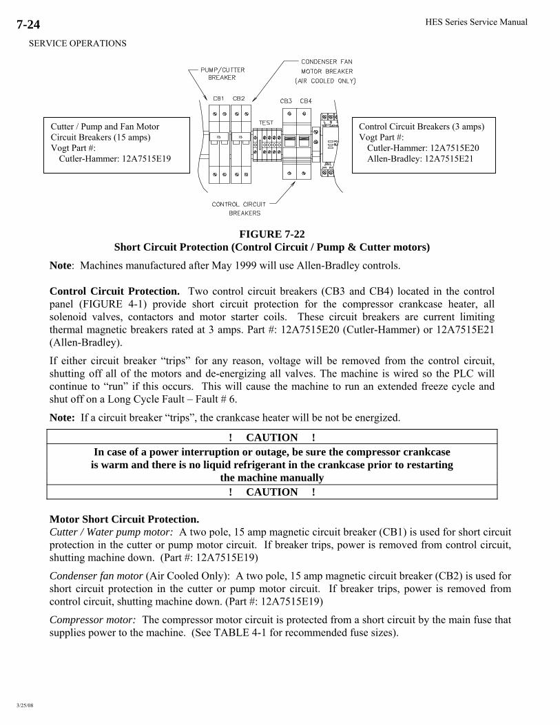
HES Series Service Manual
SERVICE OPERATIONS
3/25/08
7-24
Cutter / Pump and Fan Motor Circuit Breakers (15 amps) Vogt Part #:
Cutler-Hammer: 12A7515E19
Control Circuit Breakers (3 amps)Vogt Part #:
Cutler-Hammer: 12A7515E20 Allen-Bradley: 12A7515E21
FIGURE 7-22 Short Circuit Protection (Control Circuit / Pump & Cutter motors)
Note: Machines manufactured after May 1999 will use Allen-Bradley controls. Control Circuit Protection. Two control circuit breakers (CB3 and CB4) located in the control panel (FIGURE 4-1) provide short circuit protection for the compressor crankcase heater, all solenoid valves, contactors and motor starter coils. These circuit breakers are current limiting thermal magnetic breakers rated at 3 amps. Part #: 12A7515E20 (Cutler-Hammer) or 12A7515E21 (Allen-Bradley).
If either circuit breaker “trips” for any reason, voltage will be removed from the control circuit, shutting off all of the motors and de-energizing all valves. The machine is wired so the PLC will continue to “run” if this occurs. This will cause the machine to run an extended freeze cycle and shut off on a Long Cycle Fault – Fault # 6.
Note: If a circuit breaker “trips”, the crankcase heater will be not be energized.
! CAUTION ! In case of a power interruption or outage, be sure the compressor crankcase
is warm and there is no liquid refrigerant in the crankcase prior to restarting the machine manually
! CAUTION ! Motor Short Circuit Protection. Cutter / Water pump motor: A two pole, 15 amp magnetic circuit breaker (CB1) is used for short circuit protection in the cutter or pump motor circuit. If breaker trips, power is removed from control circuit, shutting machine down. (Part #: 12A7515E19)
Condenser fan motor (Air Cooled Only): A two pole, 15 amp magnetic circuit breaker (CB2) is used for short circuit protection in the cutter or pump motor circuit. If breaker trips, power is removed from control circuit, shutting machine down. (Part #: 12A7515E19)
Compressor motor: The compressor motor circuit is protected from a short circuit by the main fuse that supplies power to the machine. (See TABLE 4-1 for recommended fuse sizes).

HES Series Service Manual
SERVICE OPERATIONS
10/16/13
7-25
Motor Over Current Protection. Cutter / Water pump motor: The cutter and water pump motors are protected by a three phase motor
starter with adjustable bimetallic heater packs, wired for use on single phase. Can be configured to reset
automatically (“A”) or manually (“M”). PLC controlled machines will have the overload reset in the
“automatic” position. When a overload condition occurs, an auxiliary contact signals the PLC of a
problem and shuts the machine off (PLC input light # 5 will be “off” when overload is tripped). Will
automatically reset after an overloads cool.
Machine will have either Cutler-Hammer or Allen-Bradley controls. (Machines manufactured after May
1999 will use Allen-Bradley controls)
Cutler-Hammer - Use motor starter 12A7530E11 with heater packs (see table below for ratings).
Allen-Bradley - Use contactor 12A7516E23 w/solid state overload relay 12A7538E01 (rated 3.2-16A)
Current Range Setting
1/2 HP Cutter Motor Overload (Amps)
Part #: 12A 7508H2108
1/2 HP Pump Motor Overload (Amps)
Part #: 12A 7508H2109
A 3.38 4.96
B 4.10 6.03
C 4.82 7.09
D 5.54 8.16
TABLE 7-13 Cutler-Hammer Heater Pack Current Settings
The cutter motor overload should be set at the motor FLA rating. The pump motor overloads should
be set a motors Service Factor FLA rating.
Note: Water pump motor has internal thermal overload protection
FIGURE 7-23 Motor Overloads (Pump & Cutter motors)
Condenser fan motor (Air Cooled Only): The fan motor(s) on the air-cooled condenser have internal
thermal overload protection and will shut off if an overload condition occurs. If this occurs, the machine
will eventually shut off on a High / Low-pressure fault.
Compressor motor: The compressor motor has internal thermal overload protection and will shut off if
an overload condition occurs. If this occurs, the rest of the machine will continue to run but eventually
shut off on a Long cycle fault - Fault # 6.
"Current Range"
and "Auto /
Manual Reset"
adjustment
behind access
plate
Cutler-Hammer Allen-Bradley
Allen Bradley Overload Relay
Vogt Part #: 12A7538E01
Automatic or
Manual Reset
* Push to reset
Automatic
or Manual
Reset
Current
Range
Reset
After July 2007
Original AB Overload Relay
Dip switch on the side of OL Relay
Current
Range

HES Series Service Manual
SERVICE OPERATIONS
3/25/08
7-26
Ice Bin Control. The electronic bin thermostat has a LCD readout that displays the temperature in the bin at the sensor. The control has been preset and locked out at the factory to shut the machine down at 38°F and to re-start at 40°F. The control retains the program even if power is cut to the machine. NOTE: If the bin control is calling for ice, the LCD will display the current temperature and a "S1".
Replacement Sensor Vogt Part #: 12A2117G0901
Electronic Bin Thermostat Vogt Part #: 12A2117G09
To change sensor setting, Lockout, located on the inside of the unit, must be set on "unlock"
FIGURE 7–24 Electronic Bin Thermostat
Programming the Electronic Bin Thermostat. Under special conditions, the settings may need to be changed. The lockout switch is located on the inside of the control. Removal of the four screws on the face of the control will reveal the lock-switch.
Follow the instructions below to reset the switch.
1) Press the “SET” button to enter the sensors setup mode
2) Select between “C”- Celsius and “F” - Fahrenheit Use the up ↑ or down ↓ key to select “F”
3) Press the “SET” button to set the Set point (S1 will be blinking) Use the up ↑ or down ↓ key to set the temperature at 38°F
4) Press the “SET” button to set the Differential (DIF 1 will be blinking) Use the up ↑ or down ↓ key to set the differential at 2°F
5) Select between “C1”- Cooling mode and “H1” - Heating mode Use the up ↑ or down ↓ key to select “C1”
NOTE: The sensor will automatically exit the programming mode if no keys are depressed for a period of thirty seconds. Any settings that have been input to the control will be accepted at that point.

HES Series Service Manual
SERVICE OPERATIONS
3/25/08
7-27
FIGURE 7–25 Bin Thermostat Mounting Location
Electronic Bin Temperature Control Error Messages
E1 – Appears when either the up ⇧ or down ⇩ key is pressed when not in the programming mode. To correct: If the E1 message appears even when no keys are being pressed, replace the
control. E2 – Appears if the control settings are not properly stored in memory. To correct: Check all settings and correct if necessary. EP – Appears when the probe is open, shorted or sensing a temperature that is out of range. To correct: Check to see if the sensed temperature is out of range. If the sensor is subject to
a known ambient temperature between -30°F and 220°F, and displays the EP code, replace the damaged probe.
EE – Appears if the EEPROM data has been corrupted. To correct: This condition cannot be field repaired. Replace the control.
Note: Sensor cable can be extended up to 400 feet. For more information, consult Tube-Ice®
Technical Service Department.

HES Series Service Manual
SERVICE OPERATIONS
10/16/13
7-28
FIGURE 7-26 Thawing Timer. (Part of PLC)
Thawing Timer. The thawing timer governs the ice thawing period. It is built into the PLC located
inside the control panel. It is started by action of one of the freezer pressure switches (FPS1 or
FPS2) or the manual harvest button. This timer is set prior to shipment for approximately a 90
second period.
Set the thawing period for at least 20 seconds longer than the time required to harvest the entire
discharge of ice. If it should be necessary to change the setting of the timer, turn the adjustment
screw clockwise to increase the time or counter-clockwise to decrease the time. Check thaw time
after each adjustment FIGURE 7-26.
Single Ice Dual Ice
FIGURE 7-27 Selector Switch
Note: Machines manufactured after May 1999 will use Allen-Bradley controls.
Selector Switch.
Single Ice Type - A Three position rotary-type switch marked “CLEAN–OFF-ICE” used for
selecting the different machine modes. The switch is located on the control panel door.
Dual Ice Type – Two three position rotary-type switches, one marked “CLEAN-OFF-ICE” used for
selecting the different machine modes and one marked “CRU-AUTO-CYL” for selecting the type of
ice. These switches are located on the control panel door.
Vogt Part #: 12A7536M01
Note: Must be programmed at Vogt –
specify machine model when ordering
Vogt Part #:
Cutler-Hammer:
12A7500E44 (switch assy)
Allen-Bradley:
12A7500E61 (switch)
12A7500E73 (contact blk)
THAW TIMER ADJUSTMENT SCREW (LOCATED UNDER PLASTIC COVER)
RANGE: 1 ½ - 5 MINUTES
(TURN CW TO INCREASE TIME) (TURN CCW TO DECREASE TIME)
PLC: FXo PLC: FX1s
MITSUBISHI
MELSEC FX OS -14MR-
ES
PLC: FXos
THAW TIMER ADJUSTMENT SCREW
THAW TIMER ADJUSTMENT SCREW
CRU CYL
AUTO
HES Series Service Manual
SERVICE OPERATIONS
10/18/13
7-29
Pumping Down Freezer. If it should become necessary to pump the refrigerant out of the freezer,
sufficient vapor should be retained to hold one pound of pressure in the freezer so that air will not
enter if the system is opened.
A total pump down is the first phase of the clean mode. After the pump down is accomplished, put
the selector switch in the “Off” position to stop the water pump.
Note: After completing the total pump down cycle, the liquid line will remain full of liquid
refrigerant from the receiver “king” valve (58) to the liquid feed “A” solenoid valve (20).
If it becomes necessary to open freezer to the atmosphere, you will need to remove the remaining
refrigerant by using an approved refrigerant recovery unit. Isolate that part of the system by closing
the necessary hand stop valves at the receiver, condenser, compressor, etc. before using the recovery
unit and opening the system.
Pumping Down Entire System. If it should become necessary to pump down the entire system,
including the liquid line, the following should be performed. Manually open the liquid feed “A”
solenoid valve (20) by running the stem in. Close liquid outlet “king” valve (58) on the receiver
(15R). Put machine into total pump down as described above.
Removal Of Refrigerant From The Machine. To transfer the refrigerant charge from the machine
into a separate container, proceed as instructed above under pumping down freezer. This will isolate
most of the refrigerant in the receiver and the recovery unit can be connected to the access port (44)
of the liquid outlet “king” valve (58) at the bottom of the receiver. Open the valve access port by
turning the valve stem in (front seat) and operate the recovery unit until the system is considered
empty.
! WARNING !
Approved recovery equipment, hoses, gages, and refrigerant containers must be used to comply with all local and federal EPA regulations.
! WARNING !
! WARNING !
Follow these instructions carefully. Severe personal injury can result from improper
discharge of refrigerant.
! WARNING !
! WARNING !
It is not recommended that refrigerant be transferred from a refrigeration system into a cylinder. If such a transfer is made, the
refrigerant cylinder must be an approved CLEAN cylinder-- free of any contaminants or foreign materials--and must be weighed continuously to assure contents do not exceed net weight specified by cylinder manufacturer or any applicable code requirements.
! WARNING !

HES Series Service Manual
SERVICE OPERATIONS
3/25/08
7-30
Refrigerant Leaks. In addition to testing the machine for leaks as instructed under “Refrigerant Charge”, it is advisable to again make a leak test after the unit has been in operation approximately one week. Any noticeable change in operating conditions, other than shown on the “Certificate of Test” may indicate a loss of refrigerant due to a leak. Always remove the refrigerant pressure from the vessel or tubing before repairs are attempted. Non-condensable Gases. Satisfactory operation of the machine is not possible if non-condensable gases (usually air) are present in the system. Excessive condensing pressure is an indication of such gases. Excessive condensing pressure in water-cooled condensers may also be due to the accumulation of scale in the cooling coil or due to insufficient cooling water or excessive water temperature. See “Water Cooled Condensers”, Section 7. Compressor Motor Burnout. There are several causes of compressor motor burnout. Some of these are described below.
1. Low Line Voltage. A compressor motor is designed to operate within the range of plus or minus
10% of its nameplate voltage. Low voltage or excessively high voltage requires the motor windings to carry more current at the same compressor load. When this current gets too high or is applied for an extended period, the motor windings overheat, resulting in a failure or burnout.
2. Loss of Refrigerant. The hermetic compressor motor is maintained at proper operating temperature by passing cool suction gas over the motor windings. A loss of refrigerant can cause the winding to overheat resulting in a failure or burnout.
3. High Head Pressure. The system is designed to operate at 200 psig. Excessive head pressure adds refrigerating load on the compressor, which can cause the windings to overheat and result in a failure or burnout.
4. Moisture. Moisture in contact with refrigerant oil and the presence of heat will form hydrochloric or hydrofluoric acid. The acid will destroy the insulation on the motor winding causing a short circuit, which can increase motor temperature in excess of 3000°F. This extreme temperature will also create a sludge or black residue in the system.
5. Mechanical Failure. Mechanical failure has been determined as a major cause of motor burnout. Bearing wear or wipeout may allow rotor to drag--overheating the windings and burnout.
Whenever there is a compressor failure due to a motor burnout, it is important that the system be thoroughly cleaned before replacing the damaged compressor or otherwise the new compressor may also be damaged. A suction line filter should be installed and filter cores replaced until system is cleaned. Also replace the liquid line filter drier.

HES Series Service Manual
SERVICE OPERATIONS
3/25/08
7-31
Converting from Cylinder Ice to Crushed Ice (Single Ice Type Machines). • Remove jumper from #5 and #6 on terminal block and put on #5 and #4. This will reverse the
rotation of the cutter motor.
FIGURE 7-28 Terminal Block Jumper Locations
• Adjust Freezer Pressure switch (FPS2) – See table below for recommended pressure settings NOTE: Freezer pressure should be checked at freezer charging valve (# 28).
Cylinder Ice (psig) Crushed Ice (psig) Machine R22 404A R22 404A HES-20S 43 - 45 56 – 58 46 - 48 59 – 61 HES-20M 38 - 40 49 – 52 41 – 43 53 – 56 HES-30S 38 - 40 49 – 52 41 – 43 53 – 56 HES-30M 35 - 37 46 – 48 39 – 41 50 – 53 HES-40S 31 - 33 42 – 44 36 – 38 47 – 49 HES-40M 25 - 27 34 – 37 31 – 33 42 - 44
TABLE 7-14 Recommended Freezer Pressure Settings
The bottom screw is used to set the Differential
DO NOT ADJUST
Turn top screw to adjust the pressure setting (also referred to as the Range)
Clockwise = increase pressure setting Counterclockwise = decrease pressure setting
FIGURE 7-29 Freezer Pressure Switch
• The pressure switch should be adjusted until the desired ice thickness is obtained--See table below
Machine Cylinder Ice (lbs.) Crushed Ice (lbs.) HES-20S 41 – 43 30 – 32 HES-20M 40 – 42 29 – 31 HES-30S 41 – 43 30 – 32 HES-30M 40 – 42 29 – 31 HES-40S 41 – 43 30 – 32 HES-40M 40 – 42 29 – 31
TABLE 7-15 Recommended Ice Weights per cycle
Single To Dual Ice Conversion. Converting from single type to dual type ice consist of adding components, rewiring, and machine adjustments. Consult factory for single to dual ice conversion kit information.

HES Series Service Manual
SERVICE OPERATIONS
3/25/08
7-32
Defrost Pressure Switch –DPS (R404A Machines only). The DPS is used to regulate the pressure in the freezer during the harvest cycle. This pressure switch is wired in series with the D-valve (thaw gas valve), which opens and closes during the harvest cycle to maintain 90 to 95 psig in the evaporator.
CUT OUT (OPEN) ADJUSTING SCREW SET AT 95 PSIG (CW RAISES SETTING)
Vogt Part #: 12A2117B03
CUT IN (CLOSE) ADJUSTING SCREW SET AT 90 PSIG (CW LOWERS SETTING)
Defrost Pressure Switch (DPS) FIGURE 7-30
FIGURE 7-31 Defrost Pressure Switch (DPS) wiring

HES Series Service Manual
SERVICE OPERATIONS
3/25/08
7-33
Oil Separator. A coalescent type oil separator is used to return oil to the compressor when the system is subjected to extreme or unusual operating conditions.
AC&R Oil Separator (12A3025S10)
Oil Charging Fitting “T” (w/shrader fitting)
OiI Separator Vogt Part #: 12A3025S10 – AC&R (Add 14 ounces of oil when installing new) Vogt Part #: 12A3025S18 – Temprite(Add 15 ounces of oil when installing new)
FIGURE 7-32 Oil Separator / Oil Return Line
(2) Superhose – 12” long Vogt Part #: 12A2742S01
Temprite Oil Separator (12A3025S18)
Oil Strainer Vogt Part #: 12A4140S16
Ball Valve Vogt Part #: 12A4200G0211
Discharge Line Check ValveVogt Part #: 12A4200B0502
X-Valve (Used on Air Cooled machines only) Vogt Part #: See Table 7-5
Oil Sightglass

3/25/08

HES Series Service Manual
MODEL NUMBER STRUCTURE
3/25/08
8-1
8. Model Number Structure
ANominal Capacity "02K" - 2000 lbs/day ("K" = 1000's lbs/day, "T" = tons/day) "03K" - 3000 lbs/day "04K" - 4000lbs/day (Consult Specifications for Actual Capacity) "03T" - 3 tons/day "05T" - 5 tons/day "10T" - 10 tons/day "25T" - 25 tons/day "50T" - 50 tons/day "80T" - 80 tons/day
Electrical Codes "26" - 208/230-3-60 "46" - 460-3-60 "25" - 200-3-50 "45" - 400-3-50 "21" - 230-1-60
Basic Configuration "P" - Package "L" - Low-side "H" - High-side
Refrigerant "F" - R-22 "A" - Ammonia "H" - R-404a
Type of Ice "B" - Cylinder "K" - Crushed "D" - Dual Ice (Cru & Cyl)"L" - 1 1/2" Long Cylinder
Condenser Type "AC" - Air Cooled "WC" - Water Cooled "HP" - High Pressure Water Cooled "SW" - Sea Water "NC" - No Condenser
Tube Size (in 1/4's of an inch) "4" - 1" "5" - 1 1/4" "6" - 1 1/2" "8" - 2"
Product Variation Codes (A number or letter designator assigned to specific variations within a family.) "000 or Blank" – Standard Product "001" – Pillsbury Job "002" – Liquid Overfeed, Less Control Panels “003” – Liquid Overfeed, Panel shipped separate, No Wiring "RCP" – Remote Control Panel "PWS" – Part-Wind Starter "LOF" – Liquid Overfeed "120" – 120 Volt Controls "FPS" – Freezer Pressure Switch (Instead of timer) "HKA" – Insulated Casings & Part-Wind Start (Hong Kong Airport) "LCP" – Less Control Panel "45T" – Transformer added for 400-3-50, 0_K Models “SSC” – Stainless Steel Casing “VTC” – Von’s Type Cutter “ISC” – Insulated Stainless Steel Casings “SCT” – Stainless Steel Casings and Bin Thermostat
-02KA - - P FB 4 26 C RCP
Model Variation A number assigned to indicate major variations within any one family series.

3/25/08

HES-Series Service Manual
TABLES AND CHARTS
3/25/08
9-1
9. Tables and Charts
Capacity Table
Pounds of Ice Per 24 Hours
Model 90°F/32°C 80°F/26°C 70°F/21°C 60°F/15°C 50°F/10°C 40°F/4°C HES-20S 1670 1810 1950 2090 2230 2360 HES-20M 1420 1540 1660 1780 1890 2010 HES-30S 2370 2610 2830 3010 3160 3280 HES-30M 2010 2220 2400 2560 2690 2790 HES-40S 2990 3520 3730 3950 4190 4450 HES-40M 2830 2990 3170 3360 3560 3780
Ice capacities are based on 60 hz. operating current and an ambient temperature not exceeding 90°F (32°C). Reduce capacity 17% for 50 hz. operation. Reduce capacity by 3% for every 5°F over 90°F ambient.
TABLE 9-1
Suction Press (psig)
Discharge Press (psig)
Cycle Information Condenser Water (gpm) Temp (Deg. F)
End of Freeze Cylinder Ice R22 R404A R22 R404A
Suction Superheat
Deg. F
Freeze Time (Min)
Thaw Time (Min)
Ice per Cycle (lbs.)
90°
80°
70°
60°
50°
HES-20S 44 57 200 240 6 30 1.5 43 7.2 4.0 2.2 1.6 1.3 HES-20M 39 50 200 240 6 35 1.5 42 6.9 3.9 2.1 1.5 1.2 HES-30S 39 50 200 240 6 20 1.5 43 14.7 8.4 5.9 4.7 3.8 HES-30M 36 47 200 240 6 24 1.5 42 14.3 8.2 5.7 4.4 3.6 HES-40S 32 43 200 240 6 15 1.5 43 25.1 14.7 9.5 7.4 5.9 HES-40M 26 35 200 240 6 18 1.5 42 24.1 14.1 9.1 7.2 5.7
Suction Press (psig)
Discharge Press (psig)
Cycle Information Condenser Water (gpm) Temp (Deg. F)
End of Freeze Crushed Ice R22 R404A R22 R404A
Suction Superheat
Deg. F
Freeze Time (Min)
Thaw Time (Min)
Ice Per Cycle (lbs.)
90°
80°
70°
60°
50°
HES-20S 47 60 200 240 6 23 1.5 33 7.2 4.0 2.2 1.6 1.3 HES-20M 42 55 200 240 6 26 1.5 32 6.9 3.9 2.1 1.5 1.2 HES-30S 42 55 200 240 6 15 1.5 33 14.7 8.4 5.9 4.7 3.8 HES-30M 40 51 200 240 6 18 1.5 32 14.3 8.2 5.7 4.4 3.6 HES-40S 37 48 200 240 6 11 1.5 33 25.1 14.7 9.5 7.4 5.9 HES-40M 32 43 200 240 6 13 1.5 32 24.1 14.1 9.1 7.2 5.7
First Ice Out: within 15 seconds *Based on 70° make-up water All Ice Out: within 70 seconds
TABLE 9-2 Normal Operating Vitals

HES Series Service Manual
TABLES & CHARTS
5/25/11
9-2
TEMPERATURE - PRESSURE CHART FOR COMMON REFRIGERANTS
DegF R-12 R-22 R-502 R-134a MP-39 R-404a R-402a DegF R-12 R-22 R-502 R-134a MP-39 R-404a R-402a
-50 -7.6 -3.0 0.2 -9.0 -9.1 0.0 1.2 50 46.7 84.0 97.4 45.5 45.3 102.9 111.4
-48 -7.2 -2.4 0.7 -8.7 -8.7 0.8 2.1 52 48.8 87.3 101.0 47.7 60.0 109.0 120.0
-46 -6.8 -1.7 1.5 -8.3 -8.3 1.6 2.9 54 51.0 90.8 104.8 50.1 62.0 113.0 124.0
-44 -6.3 -1.0 2.3 -8.0 -7.9 2.5 3.9 56 53.2 94.3 108.6 52.3 65.0 117.0 129.0
-42 -5.8 -0.2 3.2 -7.6 -7.4 3.4 4.9 58 55.4 97.9 112.4 55.0 68.0 121.0 133.0
-40 -5.4 0.5 4.1 -7.1 -7.1 5.5 5.9 60 57.7 101.6 116.4 57.5 70.0 125.0 138.0
-38 -4.9 1.3 5.0 -6.7 -6.6 6.5 6.9 62 60.1 105.4 120.4 60.1 73.0 130.0 142.0
-36 -4.4 2.2 6.0 -6.3 -6.1 7.5 8.0 64 62.5 109.3 124.6 62.7 76.0 134.0 147.0
-34 -3.8 3.0 7.0 -5.8 -5.6 8.6 9.2 66 65.0 113.2 128.8 65.5 79.0 139.0 152.0
-32 -3.3 4.0 8.1 -5.3 -5.2 9.7 10.3 68 67.6 117.3 133.2 68.3 82.0 144.0 157.0
-30 -2.7 4.9 9.2 -4.8 -4.4 10.8 11.6 70 70.2 121.4 137.6 71.2 85.0 148.0 162.0
-28 -2.1 5.9 10.3 -4.2 -4.1 12.0 12.8 72 72.9 125.7 142.2 74.2 89.0 153.0 168.0
-26 -1.5 6.9 11.5 -3.8 -3.4 13.2 14.1 74 75.6 130.0 146.8 77.2 92.0 158.0 173.0
-24 -0.8 7.9 12.7 -3.0 -2.9 14.5 15.5 76 78.4 134.5 151.5 80.3 95.0 164.0 179.0
-22 -0.1 9.0 14.0 -2.4 -2.2 15.8 16.9 78 81.3 139.0 156.3 83.5 99.0 169.0 184.0
-20 0.6 10.1 15.3 -1.8 -1.7 17.1 18.4 80 84.2 143.6 161.2 86.8 102.0 174.0 190.0
-18 1.3 11.3 16.7 -1.1 -1.0 18.5 19.9 82 87.2 148.4 166.2 90.2 106.0 180.0 196.0
-16 2.1 12.5 18.1 -0.4 -0.2 20.0 21.5 84 90.2 153.2 171.4 93.6 109.0 185.0 202.0
-14 2.8 13.8 19.5 0.3 0.4 21.5 23.1 86 93.3 158.2 176.6 97.1 113.0 191.0 208.0
-12 3.7 15.1 21.0 1.1 1.4 23.0 24.8 88 96.5 163.2 181.9 100.7 117.0 197.0 214.0
-10 4.5 16.5 22.6 1.9 2.2 24.6 26.5 90 99.8 168.4 187.4 104.4 121.0 203.0 220.0
-8 5.4 17.9 24.2 2.8 3.1 26.3 28.3 92 103.1 173.7 192.9 108.2 125.0 209.9 227.0
-6 6.3 19.3 25.8 3.6 3.9 28.0 30.2 94 106.5 179.1 198.6 112.1 129.0 215.0 234.0
-4 7.2 20.8 27.5 4.5 4.8 29.8 32.1 96 110.0 184.6 204.3 116.1 133.0 222.0 240.0
-2 8.2 22.4 29.3 5.5 5.7 31.6 34.1 98 113.5 190.2 210.2 120.1 138.0 229.0 247.0
0 9.2 24.0 31.1 6.5 6.7 33.5 36.1 100 117.2 195.9 216.2 124.3 142.0 235.0 254.0
2 10.2 25.6 32.9 7.5 7.7 35.6 38.1 102 120.9 201.8 222.3 128.5 146.0 242.0 261.0
4 11.2 27.3 34.9 8.5 8.8 37.4 40.4 104 124.7 207.7 228.5 132.9 151.0 249.0 269.0
6 12.3 29.1 36.9 9.6 9.9 39.4 42.6 106 128.5 213.8 234.9 137.3 156.0 256.0 276.0
8 13.5 30.9 38.9 10.8 11.0 41.6 44.9 108 132.4 220.0 241.3 142.8 160.0 264.0 284.0
10 14.6 32.8 41.0 12.0 12.2 43.9 47.3 110 136.4 226.4 247.9 146.5 165.0 271.0 292.0
12 15.8 34.7 43.2 13.1 13.4 46.0 49.7 112 140.5 232.8 254.6 151.3 170.0 279.0 299.0
14 17.1 36.7 45.4 14.4 14.6 48.3 52.2 114 144.7 239.4 261.5 156.1 175.0 286.0 307.0
16 18.4 38.7 47.7 15.7 15.9 50.7 54.8 116 148.9 246.1 268.4 161.1 180.0 294.0 316.0
18 19.7 40.9 50.0 17.0 17.2 53.1 57.5 118 153.2 252.9 275.5 166.1 185.0 302.0 324.0
20 21.0 43.0 52.5 18.4 18.6 55.6 60.2 120 157.7 259.9 282.7 171.3 191.0 311.0 332.0
22 22.4 45.3 54.9 19.9 20.0 58.2 63.0 122 162.2 267.0 290.1 176.6 196.0 319.0 341.0
24 23.9 47.6 57.5 21.4 21.5 59.9 65.9 124 166.7 274.3 297.6 182.0 202.0 328.0 350.0
26 25.4 49.9 60.1 22.9 23.0 63.6 68.9 126 171.4 281.6 305.2 187.5 207.0 336.0 359.0
28 26.9 52.4 62.8 24.5 24.6 66.5 72.0 128 176.2 289.1 312.9 193.1 213.0 345.0 368.0
30 28.5 54.9 65.6 26.1 26.2 69.4 75.1 130 181.0 296.8 320.8 198.9 219.0 354.0 377.0
32 30.1 57.5 68.4 27.8 27.9 72.3 78.3 132 185.9 304.6 328.9 204.7 225.0 364.0 387.0
34 31.7 60.1 71.3 29.5 29.6 75.4 81.6 134 191.0 312.5 337.1 210.7 231.0 373.0 396.0
36 33.4 62.8 74.3 31.3 31.3 78.5 85.0 136 196.2 320.6 345.4 216.8 237.0 383.0 406.0
38 35.2 65.6 77.4 33.2 33.2 81.8 88.5 138 201.3 328.9 353.9 223.0 243.0 392.0 416.0
40 36.9 68.5 80.5 35.1 35.0 85.1 92.1 140 206.6 337.3 362.6 229.4 250.0 402.0 426.0
42 38.8 71.5 83.8 37.0 37.0 88.5 95.7 142 212.0 345.8 371.4 235.8 256.0 412.0 436.0
44 40.7 74.5 87.0 39.1 39.0 91.9 99.5 144 217.5 354.5 380.4 242.4 263.0 423.0 447.0
46 42.7 77.6 90.4 42.0 41.0 95.5 103.4 146 223.1 363.4 389.5 249.2 269.0 434.0 458.0
48 44.7 80.7 93.9 43.3 43.1 99.2 107.3 148 228.8 372.3 398.9 256.0 277.0 444.0 468.0
50 46.7 84.0 97.4 45.5 45.3 102.9 111.4 150 234.6 381.5 408.4 263.0 283.0 449.0 479.0
TABLE 9-3 All pressures are in lbs/in
2 gage (psig).

HES-Series Service Manual
TABLES AND CHARTS
3/25/08
9-3
REFERENCE INFORMATION
CONVERSION FACTORS: English to Metric
To Convert From To Multiply by
Area ft2 m2 9.2903e-2 in2 m2 6.416 e-4
Energy BTU Joule (J) 1054.48 hp BTU/Hr 2546.2 kW hp 1.34
Length ft. m. 0.3048 in. m. 0.0254
Pressure lbf/ft2 Paschals 47.88 lbf/in2 (psi) Paschals 6894.76 in. Hg psi 0.491 in H2O psi 0.03612
Temperature °F °C TC=5/9*(TF - 32) °C °F TF=(9/5*TC) + 32
Volume ft3 m3 2.8317e-2 gal (U.S.) m3 3.7854e-3 ft3 gal (U.S.) 7.48
TABLE 9-4
CONSTANTS
Specific heat of Water 1 BTU/(lbm °F) Specific heat of Air 4.19 kJ/(kg °C) 0.24 BTU/(lbm °F) Tube-Ice Density 32-35 lbs/ft3
Ice Latent Heat 144 BTU/hr
Water Sensible Heat 1 BTU/(lb °F) Ice Melting Effect (IME)
1 Ton Refrigeration 12,000 BTU/hr
Atmospheric pressure 14.7 psia
Weight of Water 62.4 lbs/ft3
8.33 lbs/gal
Weight of air 0.0749 lbs/ft3
0.0100 lbs/gal
1 Horsepower 2545.6 BTU/hr
1 Kilowatt 1.34 horsepower
Gravitational accel. 9.81 m2/sec
TABLE 9-5

5/24/11
Blank page

HES Series Service Manual
TECHNICAL SERVICE BULLETINS
3/25/08
10-1
10. Technical Service Bulletins
No. 88-5
All Models
Subject: Water Conditioning For Ice Cube Machines The quality of the ice produced by a commercial ice cube machine can only be as high as the quality of the water which is used. Water which contains turbidity or sediment or which has a high concentration of dissolved minerals or gases will produce cloudy or opaque ice. Ion exchange (zeolite) softening is used to advantage in many cases, as the softener removes iron and most forms of turbidity, and also prevents scale formation in the ice machines. However, softening the water by ion exchange does not reduce the concentration of minerals. In addition, most machines require a considerable blowdown to waste to prevent the buildup of the total dissolved solids and thus a considerable amount of softened water will be wasted. All the sulfates, chlorides, and the sodium carbonate (listed below) have in general the same effect on the appearance of raw water ice and therefore, in this rough tabulation, can be grouped together. Generally, the sodium carbonates can be considered 1 1/4 times as objectionable as the sulfates, and the chlorides about 3/4 as objectionable as the sulfates. Therefore, total the sulfates and chlorides separately and apply the factors: Calcium Sulfate Calcium Chloride Magnesium Sulfate Magnesium Chloride Sodium Sulfate Sodium Chloride Sodium Carbonate Total Sulfates x 1.0 = __________ Total Chlorides x 0.75 = __________ Sodium Carbonate x 1.25 = __________ Sum Total = __________ Dissolved solids below 171 ppm (10 grains per gallon) produces first quality ice, 256 ppm (15 g.p.g.) good quality ice, and 342 ppm (20 g.p.g.) an ice that is still marketable. If dissolved solids are between 342 ppm and 684 ppm (40 g.p.g.), acceptable ice quality ice is questionable, over 684 ppm, marketable ice cannot be expected. When cloudy or opaque is produced because of the water quality, it is suggested that the water be analyzed by a reputable laboratory and their advice be followed. Vogt Tube Ice L.L.C. Louisville, KY

3/25/08
HES Series Service Manual
INDEX
10/16/13
11-1
11. Index
A
Accumulator --------------------------------------- 3-1, 3-3, 7-2
Adapter Plate ------------------------------------------ 7-9, 7-11
Adjustable blowdown ----------------------------------------- 7-3
Automatic blowdown ----------------------------------------- 7-3
Air-cooled condenser data ---------------------------------- 5-8
Air-cooled condenser:
Cold weather kit parts ----------------------------------- 7-17
Data ---------------------------------------------------------- 7-18
Dimensions------------------------------------------------- 7-18
Wiring ------------------------------------------------- 4-15, 7-19
Allen Bradley Pressure Switch (FPS) ----------------- 7-15
Assembly Drwgs.---------------------------------------- 7-1, 7-2
Auto-restart Fault---------------------------------------------- 6-1
"A" Valve (#20) ---------------------------- 3-2, 3-3, 7-1, 7-14
B
Bearing, Cutter ----------------------------------------- 7-9, 7-11
Bill of Lading ---------------------------------------------------- 2-1
Bin, Ice Storage ----------------------------------------------- 3-4
Bin, Thermostat Adjustments ---------------------------- 7-26
Bin, Thermostat (Dual Ice type) --------------------------- 3-5
Bin, Thermostat Installation -------------------------------- 3-4
Bin, Thermostat (Single Ice type) ------------------------- 3-5
Blowdown, Adjustable --------------------------------------- 7-3
Blowdown, Automatic ---------------------------------------- 7-3
Burnout, Compressor -------------------------------------- 7-30
C
Capacity, Calculating ---------------------------------------- 6-5
Capacity, Ice Table ------------------------------------------- 9-1
Checklist, Daily ------------------------------------------------ 5-7
Checklist, Preventive Maintenance -------------------- 5-10
Check Valve ---------------------------------------------- 3-2, 3-3
Chemical Cleaning-------------------------------------------- 5-6
Chute Assembly ----------------------------------- 7-6, 7-8, 7-9
Circuit Breaker, Cutter/Pump ---------------- 4-1, 4-2, 7-24
Circuit Breaker, Control Circuit -------------- 4-1, 4-2, 7-24
Circulating Water Pump Motor ---------------------- 7-4, 7-6
Cleaning Procedure ------------------------------------------ 5-1
Clean Mode ----------------------------------------------------- 4-7
Clean/Off/ Ice Selector Switch--------------------- 4-3, 7-27
Compressor -------------------------- 3-2, 3-3, 7-1, 7-2, 7-21
Compressor Burnout ---------------------------------------- 7-30
Compressor, Contactor -------------------------------- 4-1, 4-2
Compressor Crankcase Heater ------------------------- 7-20
Compressor Lubrication ----------------------------- 5-8, 7-21
Compressor, Motor Burnout------------------------------ 7-30
Compressor, Motor Contactor ----------------------- 4-1, 4-2
Compressor, Motor Overload Protection ------------- 7-25
Condenser -------------------------------- 3-2, 3-3, 7-17, 7-18
Condenser, Air-cooled Cleaning -------------------------- 5-8
Condenser, Air-cooled Heat Rejection ---------------- 7-18
Condenser Fan Switch ------------------------------------ 7-17
Condenser, Pressure Switch (CPS) ------------------- 7-17
Condenser, Water Cooled Maintenance - 5-6, 5-7, 7-20
Control, Panel -------------------------------------------------- 4-1
Control, Panel Parts ------------------------------------ 4-1, 4-2
Controller (PLC) ----------------------------------------- 4-1, 4-5
Crankcase Heater ------------------------------------------ 7-20
Crushed Ice Preferred --------------------------------------- 3-5
Cutter, Assembly ------------------------ 7-6, 7-9, 7-10, 7-11
Cutter, Bearing ---------------------------- 7-7, 7-8, 7-9, 7-11
Cutter, Bearing Support ----------------------- 7-8, 7-9, 7-11
Cutter, Disc Assembly ------------------------------- 7-9, 7-11
Cutter, Drive Parts ------------------------------------------ 7-10
Cutter, Gear Reducer -------------------- 7-6, 7-7, 7-9, 7-10
Cutter, Motor --------------------------------------------- 7-6, 7-9
Cutter, Over Current Protection ------------------------ 7-25
Cutter, Short Circuit Protection -------------------------- 7-24
Cutter, Parts -------------------------------------------- 7-9, 7-11
Cutter, Water Tank Parts ----------------------------------- 7-9
Cylinder to Crushed Conversion ------------------------ 7-31
D
"D" Valve (Thawing Gas #18) --------------- 3-2, 3-3, 7-14
Daily Checklist ------------------------------------------------- 5-9
Discharge, Rota-lock ------------------------------- 7-12, 7-13
Divider, Bin ----------------------------------------------------- 3-4
Defrost Pressure Switch (DPS) ------------------------- 7-32
Draining Condenser ------------------------------------------ 5-6
Drip pan, maintenance -------------------------------------- 5-5
Drive gear ----------------------------------------------- 7-9, 7-10
E
Electrical Connection ---------------------------------------- 4-4
Electrical, Controls ------------------------------------------- 4-1
Electrical, Wiring Diagrams ------- 4-11, 4-12, 4-13, 4-14
Energy Saving ------------------------------------------------- 1-1
Expansion Valve ------------------------------------ 7-12, 7-13
F
Fault Identity --------------------------------------------------- 4-8
Fault Indicator Light ---------------------------------------- 4-10
Fault Mode ------------------------------------------------------ 4-8
Fault Startup Sequence ----------------------------------- 4-10
FIGURE 3-1 (Air Cooled Piping Diagram) ------------- 3-2
FIGURE 3-2 (Water Cooled Piping Diagram) --------- 3-2
FIGURE 3-3 (Bin Sensor Installation) ------------------- 3-4
FIGURE 4-1A & 4-1B (Control Panel) ------------------ 4-1
FIGURE 4-2 (Wiring & Electrical Connections) ------- 4-5
FIGURE 4-3 (PLC Display) --------------------------------- 4-6
FIGURE 4-4 (Copeland PerformanceAlert Wiring) -- 4-9
FIGURE 4-5 (Fault Startup Sequence) --------------- 4-10
FIGURE 4-6 (Fault Indicator Location) ---------------- 4-10
FIGURE 4-7 (Dual Ice, 200/208-230V Wiring) ------ 4-11
FIGURE 4-8 (Single Ice, 200/208-230V Wiring) ---- 4-12
FIGURE 4-9 (Dual Ice, 400V/460V, Wiring) --------- 4-13

HES Series Service Manual
INDEX
5/24/11
11-2
FIGURE 4-10 (Single Ice, 400/460V, Wiring) -------- 4-14
FIGURE 4-11 (AC Condenser Wiring - Single Fan) - 4-15
FIGURE 4-12 (AC Condenser Wiring - Single Fan) - 4-16
FIGURE 4-13 (AC Condenser Wiring - Dual Fan) --- 4-17
FIGURE 5-1 (Water Dist’s, Replacement Gasket)----- 5-4
FIGURE 5-2 (Scroll Compressor) ------------------------- 5-8
FIGURE 6-1 (Machine Fault Indicator Light) ----------- 6-2
FIGURE 6-2 (Fault Startup Sequence) ------------------ 6-2
FIGURE 6-3 (PLC)--------------------------------------------- 6-3
FIGURE 7-1A (Machine Layout - Front View)---------- 7-1
FIGURE 7-1B (Machine Layout - Side View)----------- 7-1
FIGURE 7-1C (Machine Layout - Rear View - WC) - 7-2
FIGURE 7-1D (Machine Layout - Rear View - AC) -- 7-2
FIGURE 7-2 (Automatic Blowdown - Harvest) --------- 7-3
FIGURE 7-3 (Float Valve - Makeup Water)------------- 7-4
FIGURE 7-4 (Circulating Water Pump) ------------------ 7-4
FIGURE 7-5 (Freezer Cover Gasket)--------------------- 7-5
FIGURE 7-6 (Cutter-Water Tank Assembly) ----------- 7-6
FIGURE 7-7 (Ice Discharge Arrangement) ------------- 7-8
FIGURE 7-8 (Cutter-Water Tank Parts) ----------------- 7-9
FIGURE 7-9 (Cutter Drive Parts) ------------------------- 7-10
FIGURE 7-10 (Cutter Parts)-------------------------------- 7-11
FIGURE 7-11 (Thermal Expansion Valve) ------------- 7-12
FIGURE 7-12 (Solenoid Valve)---------------------------- 7-14
FIGURE 7-13 (Freezer Pressure Switch)--------------- 7-15
FIGURE 7-14 (High/Low Pressure Switch) ------------ 7-16
FIGURE 7-15 (Condenser Fan Switch) ----------------- 7-17
FIGURE 7-16 (Condenser Dimensions) ---------------- 7-18
FIGURE 7-17 (Condenser Wiring) ----------------------- 7-19
FIGURE 7-18 (Water Regulating Valve)---------------- 7-19
FIGURE 7-19 (Scroll Compressor)----------------------- 7-21
FIGURE 7-20 (Suction Rota-lock Valve) --------------- 7-22
FIGURE 7-21 (Discharge Rota-lock Valve) ------------ 7-23
FIGURE 7-22 (Short Circuit Protection) ---------------- 7-24
FIGURE 7-23 (Motor Overloads) ------------------------- 7-25
FIGURE 7-24 (Ice Bin Control)---------------------------- 7-26
FIGURE 7-25 (Bin Thermostat Mounting)-------------- 7-27
FIGURE 7-26 (Thawing Timer)---------------------------- 7-28
FIGURE 7-27 (Selector Switch)--------------------------- 7-28
FIGURE 7-28 (Cyl to Cru Terminal Block Jumper) -- 7-31
FIGURE 7-29 (Freezer Pressure Switch)--------------- 7-31
Filter/Drier -------------------------------------- 3-2, 3-3, 7-1, 7-2
Float Valve (water)--------------------------------------------- 7-4
Freeze Mode ---------------------------------------------------- 4-6
Freezer------------------------------------------ 3-2, 3-3, 7-1, 7-2
Freezer, Press. Switches (FPS1 & 2) ----------- 7-15, 7-31
G
Gear Reducer -------------------------------------- 7-6, 7-9, 7-10
H
Harvest Mode --------------------------------------------------- 4-7
HE Model Structure-------------------------------------------- 8-1
Head Pressure------------------------------------------------- 7-17
Heater, Crankcase-------------------------------------------- 7-20
High-low Pressure Switch ---------------------------------- 7-16
History, Tube-Ice®--------------------------------------------- 1-1
Hub, Cutter Drive Gear -------------------------------------- 7-10
I
Ice Capacity Table ------------------------------------------ 9-1
Ice Bin Capacity---------------------------------------------- 3-4
Ice Bin Thermostat------------------------------------- 3-4, 3-5
Ice, Chute Assembly---------------------------- 7-6, 7-7, 7-8
Ice, Deflector Door ---------------------------- 7-8, 7-9, 7-11
Ice, Discharge ------------------------------------------ 3-4, 7-8
Ice, Discharge Chute --------------------------------- 7-8, 7-9
Ice, Selector Switch--------------------------- 4-1, 4-2, 7-28
Ice, Storage --------------------------------------------------- 3-4
Important Safety Notice------------------------------------ 1-2
Index ---------------------------------------------------------- 11-1
Inspection, First Arrival------------------------------------- 2-1
Introduction---------------------------------------------------- 1-1
J, K
L
Leak Detector, Halogen------------------------------------ 2-1
Low Pressure Safety Switch---------------------------- 7-16
Lubrication, Compressor ---------------------------------- 5-8
Lubrication, Cutter Gear Reducer----------------------- 5-8
M
Machine Room ----------------------------------------------- 2-2
Make-Up Water ---------------------------------------------- 7-4
Maintenance -------------------------------------------------- 5-1
Maintenance Program------------------------------ 5-9, 5-10
Major Fault ---------------------------------------------------- 6-1
Manual Harvest / Start Push Button-------------- 4-1, 4-2
Mechanical Cleaning (WC Cond ) ---------------------- 5-6
Metric Conversion ------------------------------------------- 9-3
Model Number Structure ---------------------------------- 8-1
Moisture ------------------------------------------------------ 7-30
N
NEMA----------------------------------------------------------- 2-2
Nomenclature, Piping Schematic ----------------------- 3-3
Non-Condensable Gases ------------------------------- 7-30
Normal Operating Vitals ----------------------------------- 9-1
Note To Manager -------------------------------------------- 5-9
Number Structure, HE-------------------------------------- 8-1
O
Oil Separator------------------------------------------------ 7-33
Operation Vitals --------------------------------------------- 9-1
Overload, Cutter & Pump-------------------------------- 7-25
P
Partial Pumpdown Mode ---------------------------------- 4-7
Performance Alert (Copeland) --------------------------- 4-9
Performance Alert Wiring --------------------------------- 4-9
Pin, Stainless Steel --------------------------------- 7-9, 7-11
Piping Schematic, Air-cooled----------------------------- 3-2
Piping Schematic, Water cooled ------------------------ 3-2
Piping Schematic, Nomenclature ----------------------- 3-3
PLC Display -------------------------------------------- 4-1, 4-6

HES-Series Service Manual
INDEX
5/24/11
11-3
PLC Explanation ---------------------------------------------- 4-6
PLC Inputs & Outputs---------------------------------------- 4-6
PLC Modes ----------------------------------------- 4-6, 4-7, 4-8
Power Connection -------------------------------------------- 4-5
Preventive Maintenance----------------------------- 5-9, 5-10
Principle of Operation---------------------------------------- 3-1
Programmable Controller (PLC) -------------- 4-1, 4-2, 4-6
Pump, Starter -------------------------------------------- 4-1, 4-2
Pumpdown, Partial-------------------------------------------- 4-7
Pumpdown, Total --------------------------------------------- 4-7
Pump Overload ---------------------------------- 4-2, 4-4, 7-25
Q
R
R-404A----------------------------------------------------------- 1-2
Receipt of Machine ------------------------------------------- 2-1
Receiver --------------------------------------- 3-2,3-3, 7-1, 7-2
Regulating Valve, Water ---------------------------------- 7-19
Refrigerant, Charge ------------------------------------------ 1-2
Refrigerant, Leaks ------------------------------------------ 7-28
Refrigerant, Removal -------------------------------------- 7-29
Reversing Relay ---------------------------------------- 4-2, 4-4
Rota-lock Valve, Discharge ------------------------------ 7-23
Rota-lock Valve, Suction---------------------------------- 7-22
S
Safety, Codes -------------------------------------------------- 1-3
Safety, Symbols ----------------------------------------------- 1-3
Safety, Valves-------------------------------------------- 2-2, 7-1
Sanitizing Procedure ------------------------------------------5-2
Selector Switch (SS) --------------------------- 4-2, 4-4, 7-28
Servicing Operations----------------------------------------- 7-1
Shipping Papers----------------------------------------------- 2-1
Single Ice Type ------------------------------------------------ 3-5
Single to Dual Ice Conversion --------------------------- 7-31
Solenoid Valves --------------------------------------------- 7-14
Special Precautions ------------------------------------------ 1-2
Stand-by Mode------------------------------------------------- 4-7
Start / Harvest Push Button (PB1) ----------------- 4-2, 4-4
Start-Up Mode ------------------------------------------------- 4-6
Start-Up Report---------------------------------------- Front Pg.
Storage ---------------------------------------------------------- 3-4
Strainer ---------------------------------------------- 3-2, 3-3, 7-1
Sump Area, Water Tank ------------------------------------ 7-6
Superheat ----------------------------------------------------- 7-12
Switch Plate ---------------------------------------------------- 7-1
T
Table 4-1 (Control Panel Parts List) --------------------- 4-2
Table 4-2 (Electrical Specifications) --------------------- 4-5
Table 4-3 (PLC Inputs & Outputs)------------------------ 4-6
Table 4-4 (PLC Partial Pumpdown Time) -------------- 4-7
Table 4-5 (PLC Fault Codes) ------------------------------ 4-8
Table 4-6 (Performance Alert Codes) ------------------- 4-9
Table 5-1 (Freezer Cover, Gasket, Distributors)------ 5-4
Table 5-2 (Condenser Replacement Gaskets)-------- 5-7
Table 6-1 (PLC Fault Codes) ------------------------------ 6-1
Table 6-2 (PLC Inputs and Outputs)--------------------- 6-3
Table 7-1 (Water Pump Replacement Parts) --------- 7-5
Table 7-2 (Water Distributors)----------------------------- 7-5
Table 7-3 (TXV Part #'s) ---------------------------------- 7-12
Table 7-4 (Superheat Settings) ------------------------- 7-13
Table 7-5 (Solenoid Valve Parts) ----------------------- 7-14
Table 7-6 (Kramer Cold Weather Kit Parts) --------- 7-17
Table 7-7 (Air Cooled Condenser Data) -------------- 7-18
Table 7-8 (Water Regulating Valves)------------------ 7-19
Table 7-9 (Compressor Crankcase Heaters)-------- 7-20
Table 7-10 (Compressor Info) --------------------------- 7-21
Table 7-11 (Suction Rota-lock Valve) ----------------- 7-22
Table 7-12 (Discharge Rota-lock Valve)-------------- 7-23
Table 7-13 (Overload Heater Pack Settings)-------- 7-25
Table 7-14 (Freezer Pressure Settings) -------------- 7-31
Table 7-15 (Ice Weights / Cycle) ----------------------- 7-31
Table 9-1 (Ice Capacity) ------------------------------------ 9-1
Table 9-2 (Normal Operating Vitals) --------------------- 9-1
Table 9-3 (Temperature-Pressure Chart) -------------- 9-2
Table 9-4 (English-Metric Conversion)------------------ 9-3
Table 9-5 (Constants)---------------------------------------- 9-3
Technical Service Bulletin(Water Quality) ----------- 10-1
Temperature-Pressure Chart ------------------------------ 9-2
Thawing, Chamber ------------------------------------- 3-2, 3-3
Thawing, Mode ------------------------------------------------ 4-7
Thawing, Timer ---------------------------------------------- 7-28
Thermostat, Adjustments --------------------------------- 7-26
Thermostat, Bin Installation-------------------------------- 3-4
Timer, Thawing ---------------------------------------------- 7-28
Total Pumpdown Mode-------------------------------------- 4-7
Troubleshooting ----------------------------------------------- 6-1
U
V
Vitals, Operation ---------------------------------------------- 9-1
W
Warranty (Basic Product)--------------------------- Rear Pg.
Warranty Registration ------------------------------- Front Pg.
Water Conditioning ----------------------------------------- 10-1
Water Cooled Condenser--------------------- 3-2, 3-3, 7-20
Water Distributor ---------------------------------------- 5-4, 7-5
Water Pump---------------------------- 3-2, 3-3, 7-1, 7-4, 7-6
Water Regulating Valve----------------------------------- 7-19
Water Quality ------------------------------------------------ 10-1
Water Tank ----------------------------------- 3-2, 3-3, 7-8, 7-9
Water Tank, Cover ------------------------------------- 7-8, 7-9
Water Tank, Maintenance ---------------------------------- 5-5
Water Tank, Parts -------------------------------------- 7-8, 7-9
Wiring and Electrical Connection ------------------------ 4-4
Wiring Schematic, (Dual Ice) ---------------------------- 4-11
Wiring Schematic, (Single Ice) -------------------------- 4-12
Wiring Schematic, (Single Ice–Dual Voltage) ------ 4-13
Wiring Schematic, (Single Ice, 400/460V) ----------- 4-14
X
"X" Valve ( #53 )--------------------------------- 3-2, 3-3, 7-14
Y, Z

5/24/11

HES Series Warranty Outline
10/16/13
1. Standard Warranty
• 36-Months from start-up date on all parts.
• Start-up date determined by Start-up Report.
• Ship date from factory used if no Start-up Report on file.
• Vogt may require return of defective parts.
• The standard warranty is not transferable.
2. Extended Warranty
• 5-years total on the compressor.
• 5-years total on the cutter assembly excluding the drive train and bearings.
• Lifetime (25-years) on the evaporator (freezer) and refrigerant receiver.
• All extensions of warranty are for the exclusive use of the original end user only and
are not transferable.
• The 2-year extension on the compressor warranty applies only to units installed in
the United States of America and it’s territories.
• The 2-year extension on the compressor warranty will not apply when the Tube-Ice
machine is installed or modified with a heat reclaim device other than those sold by
Vogt unless we have accepted modifications for specific installations in writing.
• Only a qualified refrigeration technician with EPA Certification will be allowed to
diagnose and replace a failed compressor under warranty.
• Damage to the evaporator tubes as a result of expansion caused by re-freezing of ice
or corrosion damage due to water quality is not covered.
3. Labor Warranty
• 36-Months from the date of start-up.
• A Vogt approved Start-up Report must be on file at the factory.
• Only technicians with EPA Certification will be allowed to perform service under
the Labor Warranty Policy.
• Warranty labor claim forms must be completed detailing all information and
received by the factory within 45-days of the repair date.
• The labor warranty applies only to the original end user and only on those units
installed within the United States of America.
• The labor warranty covers replacement of failed parts and repair of defective
workmanship in accordance with established guidelines.
The Warranty does not cover the following:
• Adjustment to the machine with no problem found.
• Premium labor rates, holiday, overtime, etc.
• Additional labor charges due to inaccessibility of the ice machine.
• Repairs resulting from electrical supply, water supply, or drainage, flood,
storm, or other acts of God.
• Repairs caused by machine modification without Vogt’s written approval.
• Repairs to remote air-cooled condensers and ice spreader kits.
• Repairs due to improper installation of the ice machine.
Refrigerant is not covered under this warranty.

5/24/11
Blank page

VOGT® HES SERIES TUBE-ICE® MACHINE BASIC PRODUCT WARRANTY
Vogt Ice, LLC. hereinafter referred to as SELLER, warrants every Vogt Tube-Ice® Machine Model HES20, HES30, and HES40 to be free from defects in material and workmanship, if properly installed, maintained and operated under normal use for a period of 36 months from date of original installation or 36 months from date of shipment from SELLER’S plant if the SELLER does not have an accepted start-up form on file. The obligation of the SELLER under this warranty is limited to the repair or replacement of parts or assemblies that in the SELLER’S opinion are defective, F.O.B. the factory. In addition to the component warranty explained above, the SELLER will pay straight time labor to repair or replace a defective component when failure occurs within 36 months from the date of original installation provided that the SELLER has an accepted start-up form on file. Such service can only be performed by a SELLER approved service representative or a refrigeration service agency as qualified and authorized by the SELLER’S distributor. The date of installation for both the component and labor warranties will be determined by the SELLER from an accepted machine start-up form. To secure prompt and continuing warranty service, the start-up form must be fully completed and sent to the SELLER within thirty (30) days from the installation date. The above labor warranty applies only to the original end user and for machines installed in the UNITED STATES OF AMERICA and is not applicable to remote air cooled condensers or ice spreader kits. The component and labor warranties are not applicable to installation related components such as remote air-cooled condenser lines, bins, external electrical components and external water and drain lines. Loss of refrigerant and replacement thereof is not covered by this warranty. Time and hourly rate schedules, as published by the SELLER, apply to all service procedures. Additional expense including, but not limited to, overtime premium, travel time, material cost, accessing of the Tube-Ice® machine, is the responsibility of the owner, along with all maintenance, adjustments, cleaning and ice purchases. Any alteration in material or design of SELLER’S product or component parts thereof by PURCHASER or others without written authorization by SELLER, problems with the electrical supply, water supply, flood, storm or other acts of God will void all obligations of SELLER regarding the product and any associated warranty herein stated or implied. SELLER’S sole liability shall be exclusively as set forth herein, and SELLER shall not be liable for any incidental or consequential damages due to its breach of any warranty herein contained, or otherwise. Without limitation to the foregoing, in no event shall SELLER be liable for the loss of the product or for the loss of use of any other product, process, plant,
equipment, or facilities of the PURCHASER whether partially or wholly due to defects in material and/or workmanship and/or design of SELLER’S product, and in no event shall SELLER be liable for removal of appurtenances or incidentals such as connections, pipework and similar items of obstruction or for any cost brought about by the necessity of removing the product from its point of installation. SELLER makes no warranty of any kind whatsoever, express or implied, other than as specifically stated herein; and there are no warranties of merchantability and/or fitness for a particular purpose which exceed the obligations and warranties specifically stated herein.
FIVE-YEAR EXTENDED WARRANTY At the termination of the two year component warranty period above, SELLER hereby extends this warranty for three years to cover COMPRESSORS AND CUTTER ASSEMBLIES, EXCLUDING THE CUTTER BEARINGS AND DRIVE TRAINS. The five year compressor parts warranty shall not apply when the Tube-Ice® machine is installed or modified with a condenser or a heat reclaim device other than those sold by SELLER unless SELLER has accepted modifications for specific installations in writing. The extended warranty, as it applies to the COMPRESSOR covers only those machines installed in THE UNITED STATES OF AMERICA AND IT’S TERRITORIES.
LIFETIME WARRANTY* This component warranty is further extended for the life of the machine to cover the EVAPORATOR (FREEZER), FRAME, CIRCULATING WATER TANK AND REFRIGERANT RECEIVER, EXCLUDING GAGE GLASS ASSEMBLIES AND VALVES. Damage to evaporator tubes as a result of expansion caused by re-freezing of ice or corrosion damage due to water quality is specifically excluded. These extensions of warranty and the labor warranty apply only to VOGT® TUBE-ICE® MACHINE MODELS HES20, HES30 and HES40 for the exclusive use of the PURCHASER or original end user, as defined above. All other obligations, terms and conditions of the Basic Product Warranty apply to the Extended Warranty.
*“Lifetime” is defined as 25 years. Vogt® and Tube-Ice
® are registered
trademarks of Vogt Ice, LLC, 1000 West Ormsby Ave., Louisville, Kentucky 40210