Embed Size (px)
Citation preview
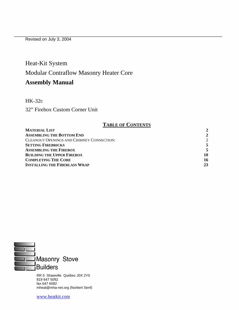
Revised on July 3, 2004
Heat-Kit System Modular Contraflow Masonry Heater Core Assembly Manual HK-32c 32” Firebox Custom Corner Unit
TABLE OF CONTENTS MATERIAL LIST 2 ASSEMBLING THE BOTTOM END 2 CLEANOUT OPENINGS AND CHIMNEY CONNECTION: 2 SETTING FIREBRICKS 5 ASSEMBLING THE FIREBOX 5 BUILDING THE UPPER FIREBOX 10 COMPLETING THE CORE 16 INSTALLING THE FIBERLASS WRAP 23
RR 5 Shawville Québec J0X 2Y0 819 647 5092 fax 647 6082 [email protected] (Norbert Senf) www.heatkit.com
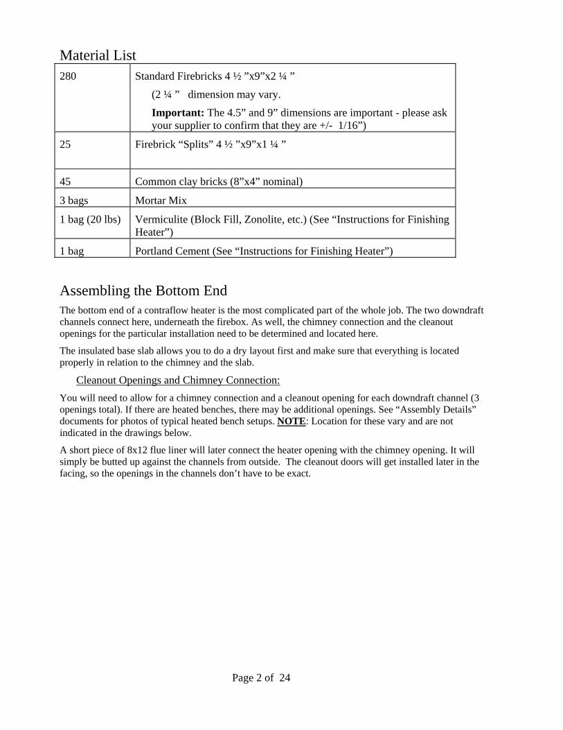
Material List 280 Standard Firebricks 4 ½ ”x9”x2 ¼ ”
(2 ¼ ” dimension may vary.
Important: The 4.5” and 9” dimensions are important - please ask your supplier to confirm that they are +/- 1/16”)
25 Firebrick “Splits” 4 ½ ”x9”x1 ¼ ”
45 Common clay bricks (8”x4” nominal)
3 bags Mortar Mix
1 bag (20 lbs) Vermiculite (Block Fill, Zonolite, etc.) (See “Instructions for Finishing Heater”)
1 bag Portland Cement (See “Instructions for Finishing Heater”)
Assembling the Bottom End The bottom end of a contraflow heater is the most complicated part of the whole job. The two downdraft channels connect here, underneath the firebox. As well, the chimney connection and the cleanout openings for the particular installation need to be determined and located here.
The insulated base slab allows you to do a dry layout first and make sure that everything is located properly in relation to the chimney and the slab.
Cleanout Openings and Chimney Connection: You will need to allow for a chimney connection and a cleanout opening for each downdraft channel (3 openings total). If there are heated benches, there may be additional openings. See “Assembly Details” documents for photos of typical heated bench setups. NOTE: Location for these vary and are not indicated in the drawings below.
A short piece of 8x12 flue liner will later connect the heater opening with the chimney opening. It will simply be butted up against the channels from outside. The cleanout doors will get installed later in the facing, so the openings in the channels don’t have to be exact.
Page 2 of 24
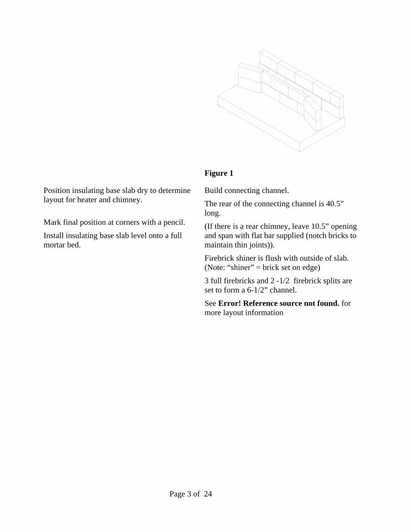
Figure 1
Position insulating base slab dry to determine layout for heater and chimney.
Mark final position at corners with a pencil.
Install insulating base slab level onto a full mortar bed.
Build connecting channel.
The rear of the connecting channel is 40.5” long.
(If there is a rear chimney, leave 10.5” opening and span with flat bar supplied (notch bricks to maintain thin joints)).
Firebrick shiner is flush with outside of slab. (Note: “shiner” = brick set on edge)
3 full firebricks and 2 -1/2 firebrick splits are set to form a 6-1/2” channel.
See Error! Reference source not found. for more layout information
Page 3 of 24

Figure 2
Figure 3
Figure 4
Figure 5
Form connecting channel ceiling as shown. The two endpieces are precast (supplied).
Use a sponge and water to clean any hanging mortar drips from the inside of channel.
To form support for firebox floor, use common brick and mortar to build up fill as shown to same height as firebrick. Fill all gaps solid with mortar. Leave approx. 8 - 10” channel for ashes.
Install 2 14” flatbars as shown to provide extra support for firebox floor. Use mortar joint underneath flat bars to gain height
Page 4 of 24
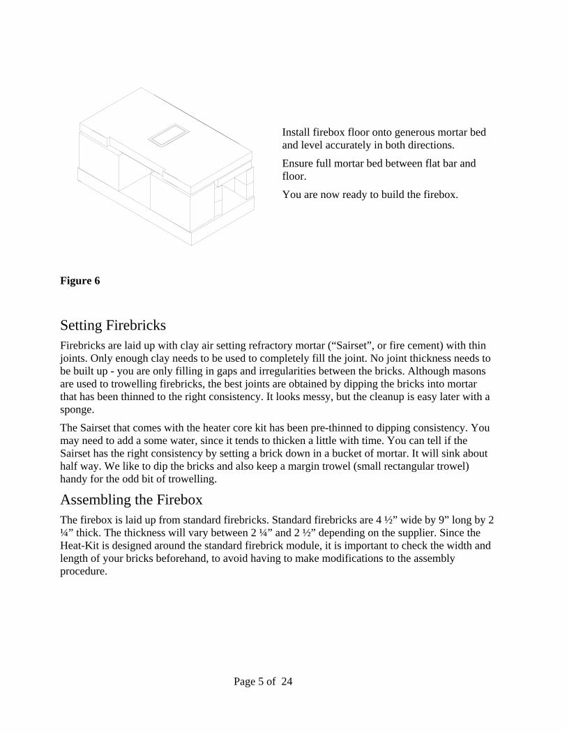
Figure 6
Install firebox floor onto generous mortar bed and level accurately in both directions.
Ensure full mortar bed between flat bar and floor.
You are now ready to build the firebox.
Setting Firebricks Firebricks are laid up with clay air setting refractory mortar (“Sairset”, or fire cement) with thin joints. Only enough clay needs to be used to completely fill the joint. No joint thickness needs to be built up - you are only filling in gaps and irregularities between the bricks. Although masons are used to trowelling firebricks, the best joints are obtained by dipping the bricks into mortar that has been thinned to the right consistency. It looks messy, but the cleanup is easy later with a sponge.
The Sairset that comes with the heater core kit has been pre-thinned to dipping consistency. You may need to add a some water, since it tends to thicken a little with time. You can tell if the Sairset has the right consistency by setting a brick down in a bucket of mortar. It will sink about half way. We like to dip the bricks and also keep a margin trowel (small rectangular trowel) handy for the odd bit of trowelling.
Assembling the Firebox The firebox is laid up from standard firebricks. Standard firebricks are 4 ½” wide by 9” long by 2 ¼” thick. The thickness will vary between 2 ¼” and 2 ½” depending on the supplier. Since the Heat-Kit is designed around the standard firebrick module, it is important to check the width and length of your bricks beforehand, to avoid having to make modifications to the assembly procedure.
Page 5 of 24
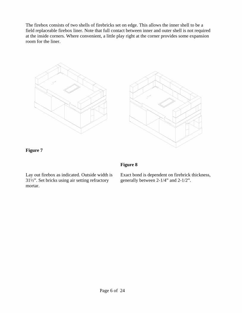
The firebox consists of two shells of firebricks set on edge. This allows the inner shell to be a field replaceable firebox liner. Note that full contact between inner and outer shell is not required at the inside corners. Where convenient, a little play right at the corner provides some expansion room for the liner.
Figure 7
Figure 8
Lay out firebox as indicated. Outside width is 31½”. Set bricks using air setting refractory mortar.
Exact bond is dependent on firebrick thickness, generally between 2-1/4” and 2-1/2”.
Page 6 of 24

Figure 9
Figure 10
Top front firebricks are notched 1/4” x 4” for firebox lintel.
Figure 11
Figure 12
Begin inner firebox. Note that the bricks are left about 1/4” short at the blind inside corners.
The inner firebox is set dry against the outer firebox. There is no mortar joint between the
Page 7 of 24
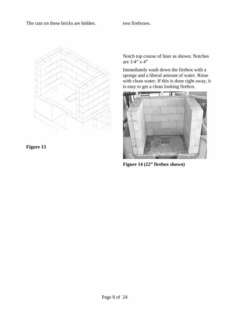
The cuts on these bricks are hidden. two fireboxes.
Figure 13
Notch top course of liner as shown. Notches are 1/4” x 4”
Immediately wash down the firebox with a sponge and a liberal amount of water. Rinse with clean water. If this is done right away, it is easy to get a clean looking firebox.
Figure 14 (22” firebox shown)
Page 8 of 24

Figure 15
Firebrick floor slopes are glued in place with Sairset - this can be done later.
Figure 16
Notch the two front bricks on the top course 1/4” X 4” as shown. This provides space for the firebox lintel shown in Figure 17
Page 9 of 24
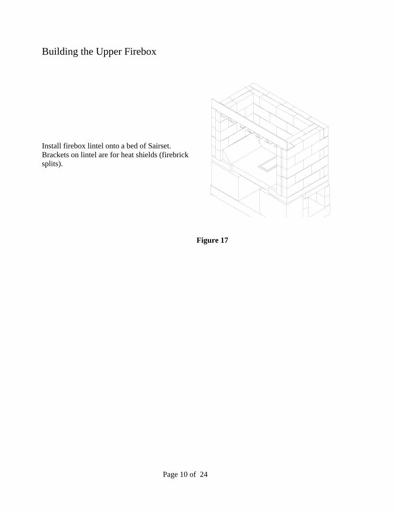
Building the Upper Firebox
Install firebox lintel onto a bed of Sairset. Brackets on lintel are for heat shields (firebrick splits).
Figure 17
Page 10 of 24

Figure 18
Lay up next course as shown. Use a dry joint with lintel.
Round the bricks slightly where they meet the inside corner of the lintel to get a tighter fit.
There should be about 1/8” gap between lintel and bricks.
Figure 19
If you have access to strapping tools, this course can be strapped as shown. This is optional. If a strap is used, then round outside corners of bricks slightly.
The purpose of the strap is to transfer weight onto the outer firebox.
This allows the complete inner firebox to be removed, if necessary, rather than in sections.
Page 11 of 24
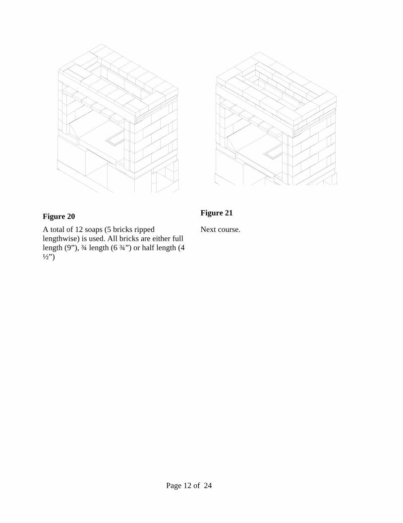
Figure 20 Figure 21
A total of 12 soaps (5 bricks ripped lengthwise) is used. All bricks are either full length (9”), ¾ length (6 ¾”) or half length (4 ½”)
Next course.
Page 12 of 24
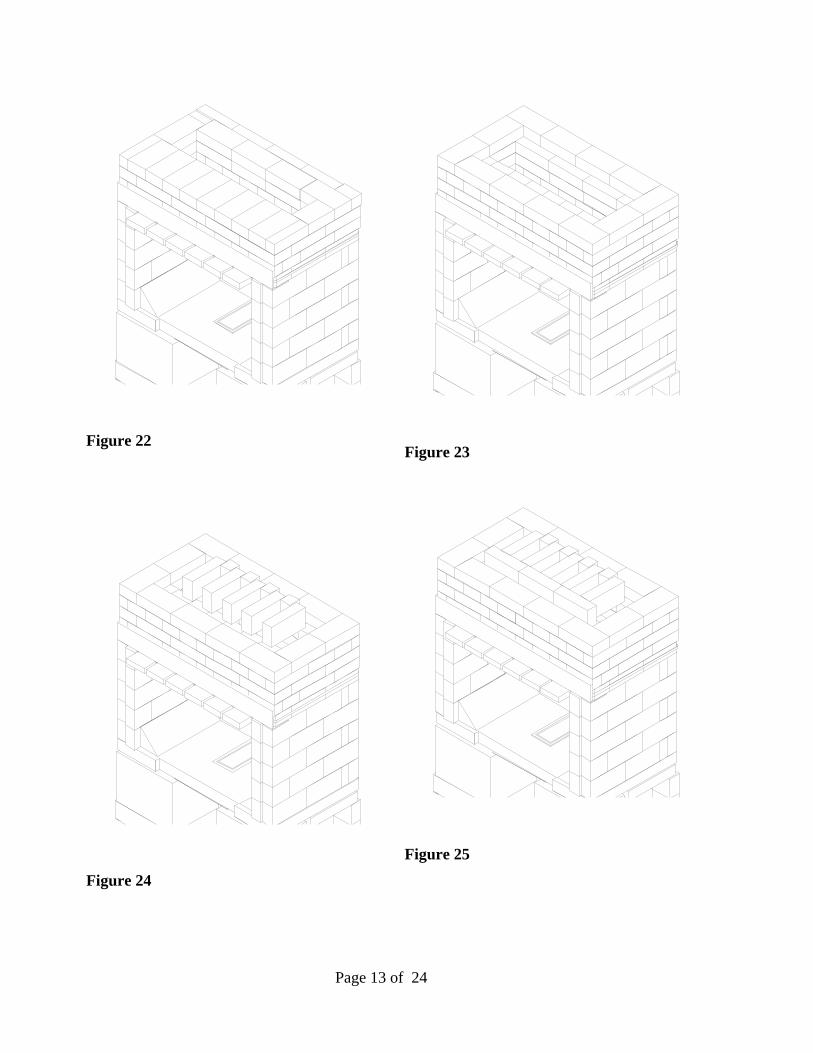
Figure 22 Figure 23
Figure 24
Figure 25
Page 13 of 24

Figure 26 Figure 27
Figure 28
Figure 29
Page 14 of 24
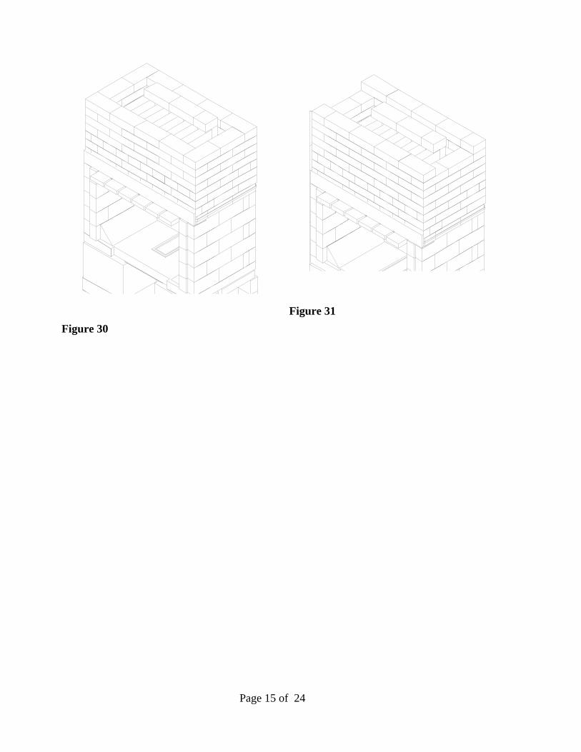
Figure 30 Figure 31
Page 15 of 24
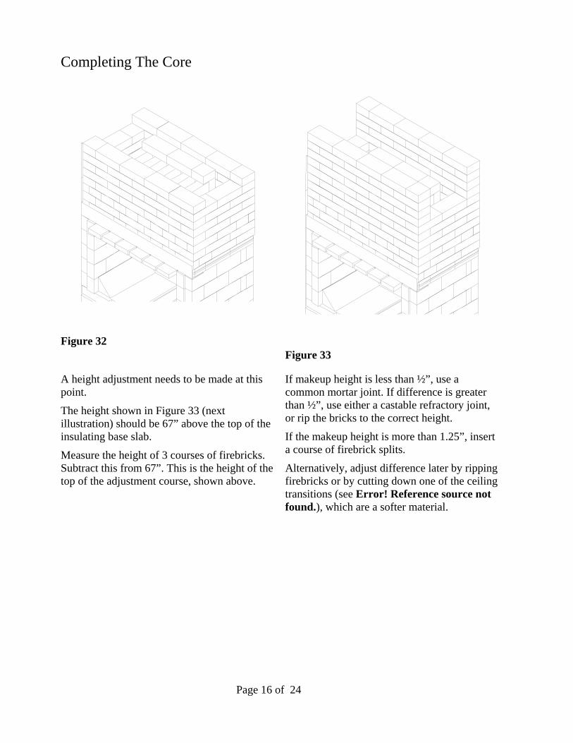
Completing The Core
Figure 32 Figure 33
A height adjustment needs to be made at this point.
The height shown in Figure 33 (next illustration) should be 67” above the top of the insulating base slab.
Measure the height of 3 courses of firebricks. Subtract this from 67”. This is the height of the top of the adjustment course, shown above.
If makeup height is less than ½”, use a common mortar joint. If difference is greater than ½”, use either a castable refractory joint, or rip the bricks to the correct height.
If the makeup height is more than 1.25”, insert a course of firebrick splits.
Alternatively, adjust difference later by ripping firebricks or by cutting down one of the ceiling transitions (see Error! Reference source not found.), which are a softer material.
Page 16 of 24
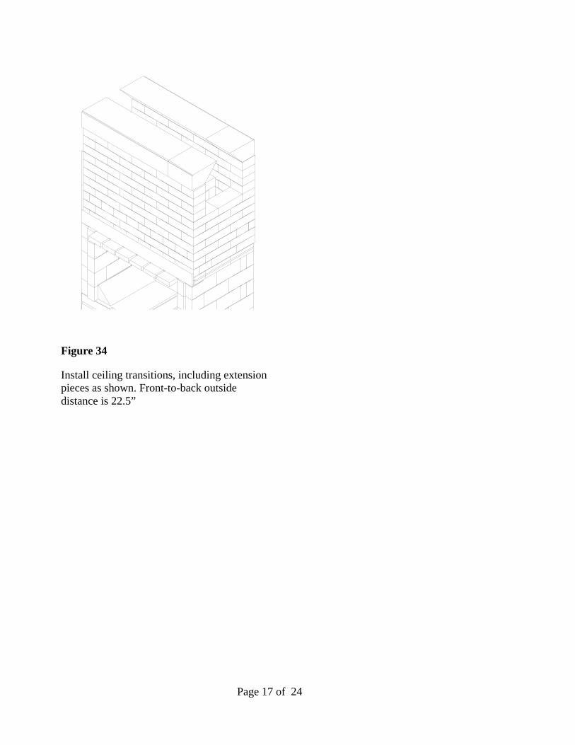
Figure 34
Install ceiling transitions, including extension pieces as shown. Front-to-back outside distance is 22.5”
Page 17 of 24

Figure 35 (shows standard core w. rear oven)
Figure 36
View from front.
Page 18 of 24
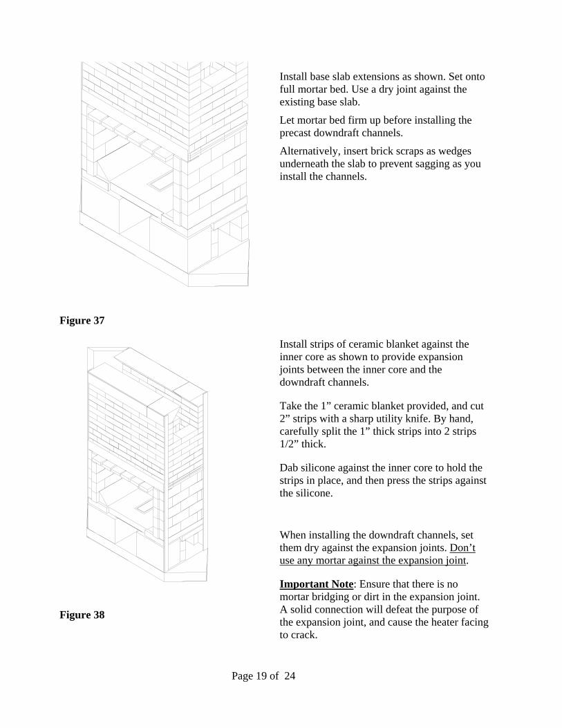
Figure 37
Install base slab extensions as shown. Set onto full mortar bed. Use a dry joint against the existing base slab.
Let mortar bed firm up before installing the precast downdraft channels.
Alternatively, insert brick scraps as wedges underneath the slab to prevent sagging as you install the channels.
Figure 38
Install strips of ceramic blanket against the inner core as shown to provide expansion joints between the inner core and the downdraft channels.
Take the 1” ceramic blanket provided, and cut 2” strips with a sharp utility knife. By hand, carefully split the 1” thick strips into 2 strips 1/2” thick.
Dab silicone against the inner core to hold the strips in place, and then press the strips against the silicone.
When installing the downdraft channels, set them dry against the expansion joints. Don’t use any mortar against the expansion joint.
Important Note: Ensure that there is no mortar bridging or dirt in the expansion joint. A solid connection will defeat the purpose of the expansion joint, and cause the heater facing to crack.
Page 19 of 24
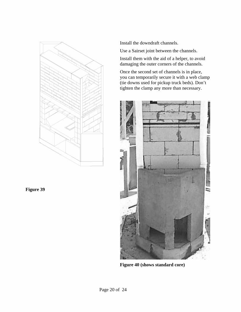
Figure 39
Install the downdraft channels.
Use a Sairset joint between the channels.
Install them with the aid of a helper, to avoid damaging the outer corners of the channels.
Once the second set of channels is in place, you can temporarily secure it with a web clamp (tie downs used for pickup truck beds). Don’t tighten the clamp any more than necessary.
Figure 40 (shows standard core)
Page 20 of 24

Figure 41 Figure 42
Secure channels to core with concrete tie wire or straps. If you use straps, use only a slight amount of pressure to avoid compressing expansion joints.
Install 3 piece ceiling slab. Slabs are set on dry.
Use a helper, and set up adequate staging (foot planks). Install smooth side down.
Page 21 of 24

Figure 43
Figure 44
Install triangular ceiling slab extension pieces, using clear silicone to make tight joints with main ceiling slab and with top of downdraft channels.
Using clear silicone, carefully seal all ceiling slab joints, particularly the shiplap joints and the bottom joint.
Page 22 of 24
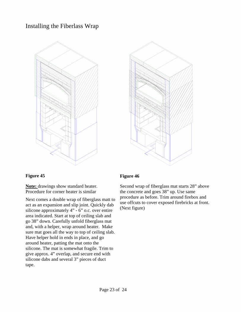
Installing the Fiberlass Wrap
Figure 45
Figure 46
Note: drawings show standard heater. Procedure for corner heater is similar
Next comes a double wrap of fiberglass matt to act as an expansion and slip joint. Quickly dab silicone approximately 4” - 6” o.c. over entire area indicated. Start at top of ceiling slab and go 38” down. Carefully unfold fiberglass mat and, with a helper, wrap around heater. Make sure mat goes all the way to top of ceiling slab. Have helper hold in ends in place, and go around heater, patting the mat onto the silicone. The mat is somewhat fragile. Trim to give approx. 4” overlap, and secure end with silicone dabs and several 3” pieces of duct tape.
Second wrap of fiberglass mat starts 28” above the concrete and goes 38” up. Use same procedure as before. Trim around firebox and use offcuts to cover exposed firebricks at front. (Next figure)
Page 23 of 24
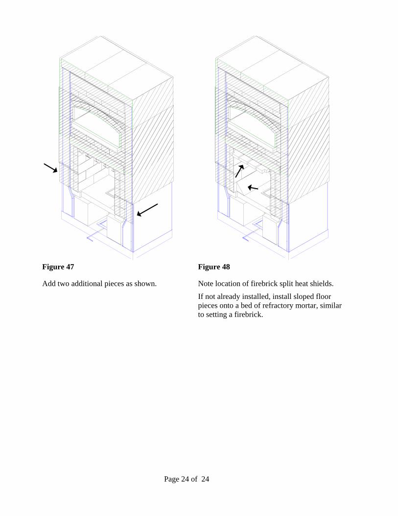
Figure 47
Figure 48
Add two additional pieces as shown. Note location of firebrick split heat shields.
If not already installed, install sloped floor pieces onto a bed of refractory mortar, similar to setting a firebrick.
Page 24 of 24