Embed Size (px)
Citation preview
Heat Recovery Steam
Generators for Flexibility
Landon Tessmer
IAGT October 2016
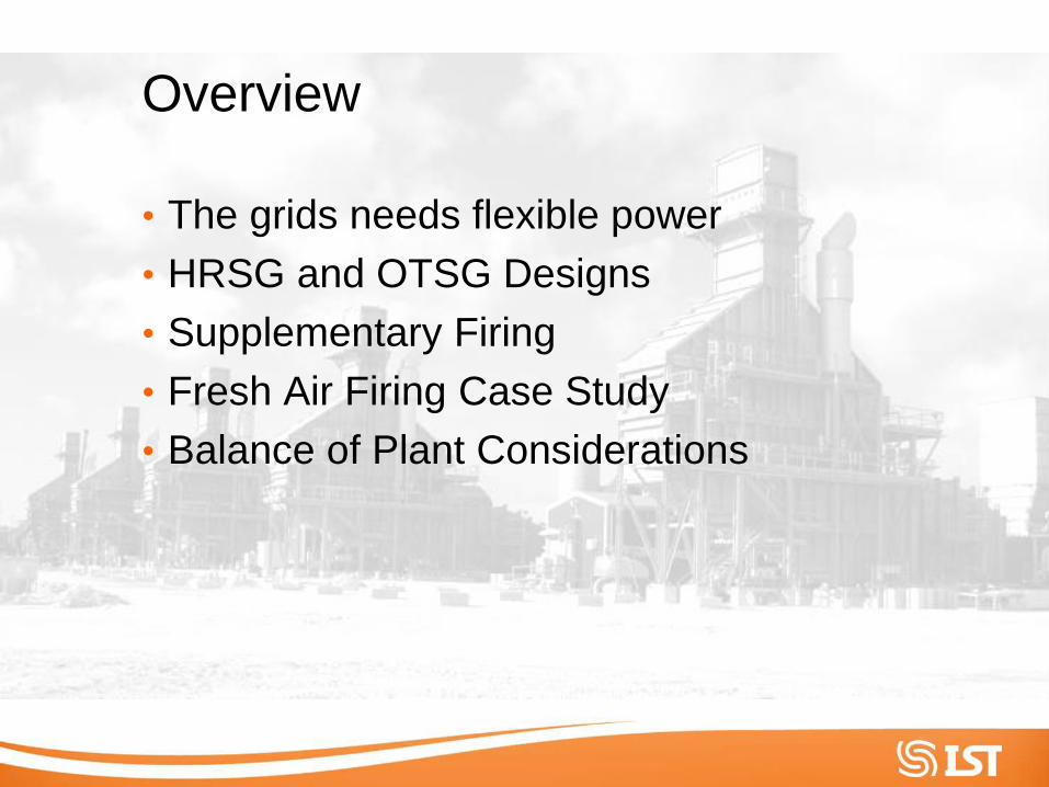
Overview
• The grids needs flexible power
• HRSG and OTSG Designs
• Supplementary Firing
• Fresh Air Firing Case Study
• Balance of Plant Considerations

The Grid Needs Flexible Power
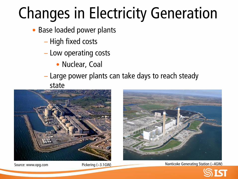
Changes in Electricity Generation • Base loaded power plants
– High fixed costs
– Low operating costs
• Nuclear, Coal
– Large power plants can take days to reach steady state
Source: www.opg.com Pickering (~3.1GW) Nanticoke Generating Station (~4GW)

Changes in Electricity Generation • Peaking Power Plants
– Simple Cycle Power Plants
– Combined Cycle Power Plants (CCPPs)
– Hydroelectric
– Renewables
Source: www.opg.com
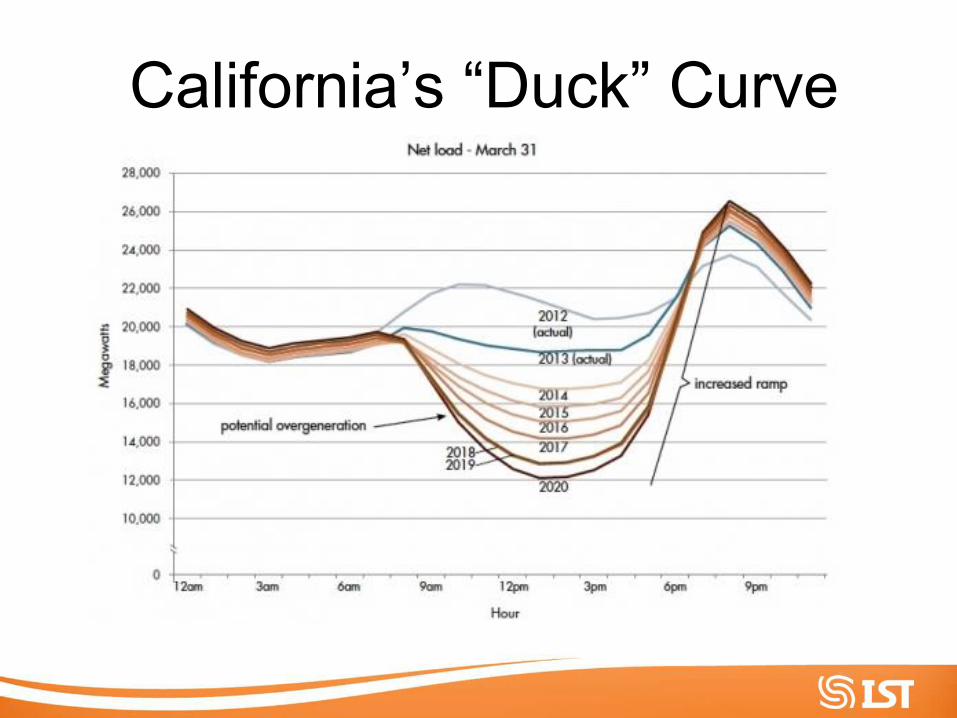
California’s “Duck” Curve
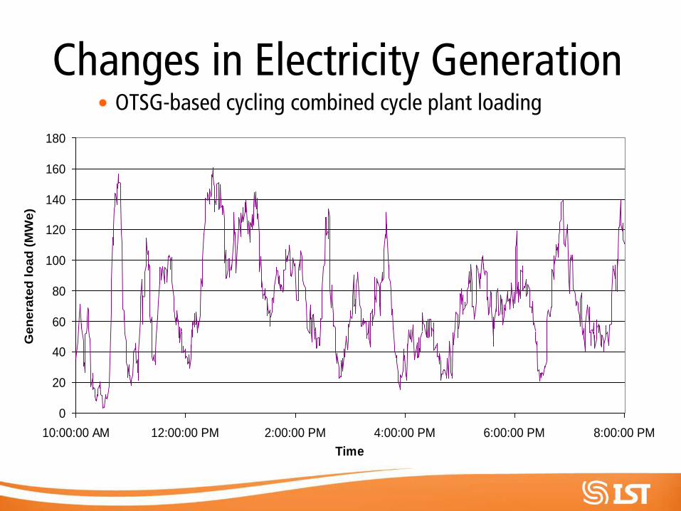
Changes in Electricity Generation • OTSG-based cycling combined cycle plant loading
0
20
40
60
80
100
120
140
160
180
10:00:00 AM 12:00:00 PM 2:00:00 PM 4:00:00 PM 6:00:00 PM 8:00:00 PM
Time
Gen
era
ted
lo
ad
(M
We)
Changes in Electricity Generation
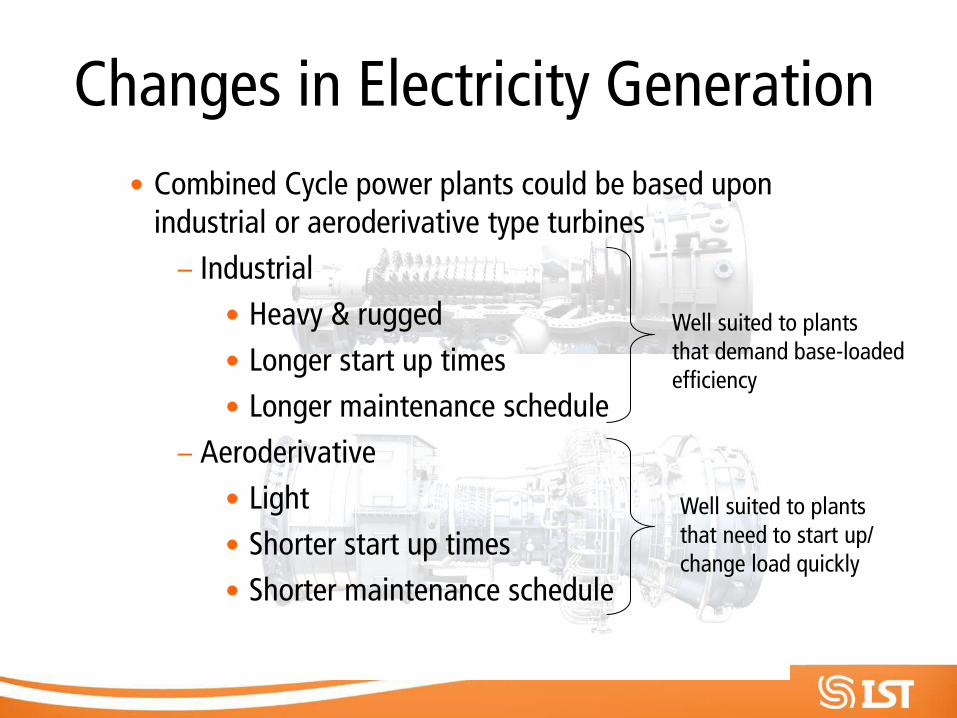
• Combined Cycle power plants could be based upon industrial or aeroderivative type turbines
– Industrial
• Heavy & rugged
• Longer start up times
• Longer maintenance schedule
– Aeroderivative
• Light
• Shorter start up times
• Shorter maintenance schedule
Well suited to plants that need to start up/ change load quickly
Well suited to plants that demand base-loaded efficiency
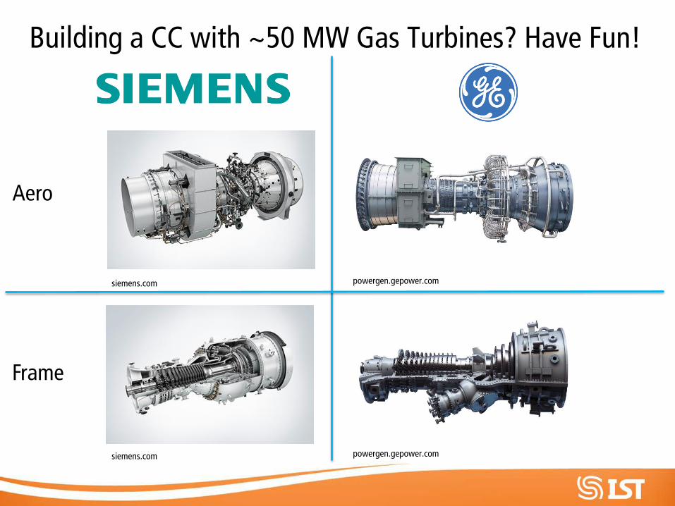
siemens.com powergen.gepower.com
Building a CC with ~50 MW Gas Turbines? Have Fun!
Aero
Frame
siemens.com powergen.gepower.com
Flexible HRSG Designs
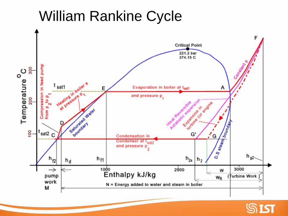
William Rankine Cycle
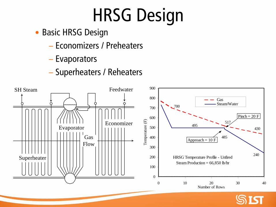
HRSG Design • Basic HRSG Design
– Economizers / Preheaters
– Evaporators
– Superheaters / Reheaters
SH Steam Feedwater
EconomizerEvaporator
Superheater
Gas
Flow
HRSG Temperature Profile - Unfired
Steam Production = 66,850 lb/hr
430
517
700
240
495
485
0
100
200
300
400
500
600
700
800
900
0 10 20 30 40Number of Rows
Tem
per
ature
(F
)
Gas Steam/Water
Pinch = 20 F
Approach = 10 F
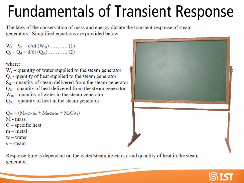
Fundamentals of Transient Response
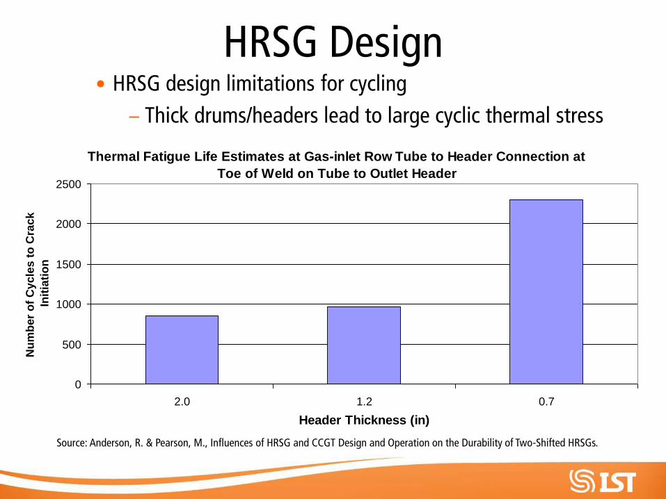
HRSG Design • HRSG design limitations for cycling
– Thick drums/headers lead to large cyclic thermal stress
Thermal Fatigue Life Estimates at Gas-inlet Row Tube to Header Connection at
Toe of Weld on Tube to Outlet Header
0
500
1000
1500
2000
2500
2.0 1.2 0.7
Header Thickness (in)
Nu
mb
er
of
Cycle
s t
o C
rack
Init
iati
on
Source: Anderson, R. & Pearson, M., Influences of HRSG and CCGT Design and Operation on the Durability of Two-Shifted HRSGs.
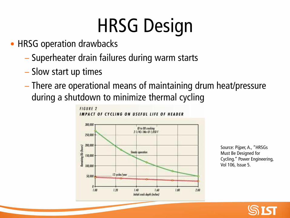
HRSG Design • HRSG operation drawbacks
– Superheater drain failures during warm starts
– Slow start up times
– There are operational means of maintaining drum heat/pressure during a shutdown to minimize thermal cycling
Source: Pijper, A., “HRSGs Must Be Designed for Cycling.” Power Engineering, Vol 106, Issue 5.
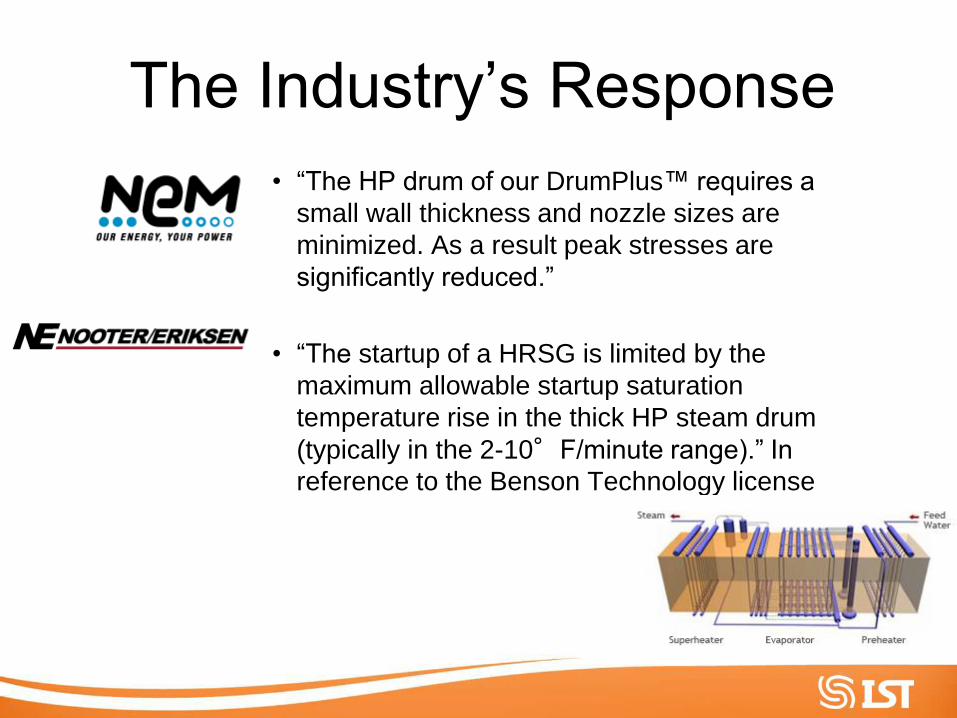
The Industry’s Response
• “The HP drum of our DrumPlus™ requires a
small wall thickness and nozzle sizes are
minimized. As a result peak stresses are
significantly reduced.”
• “The startup of a HRSG is limited by the
maximum allowable startup saturation
temperature rise in the thick HP steam drum
(typically in the 2-10°F/minute range).” In
reference to the Benson Technology license
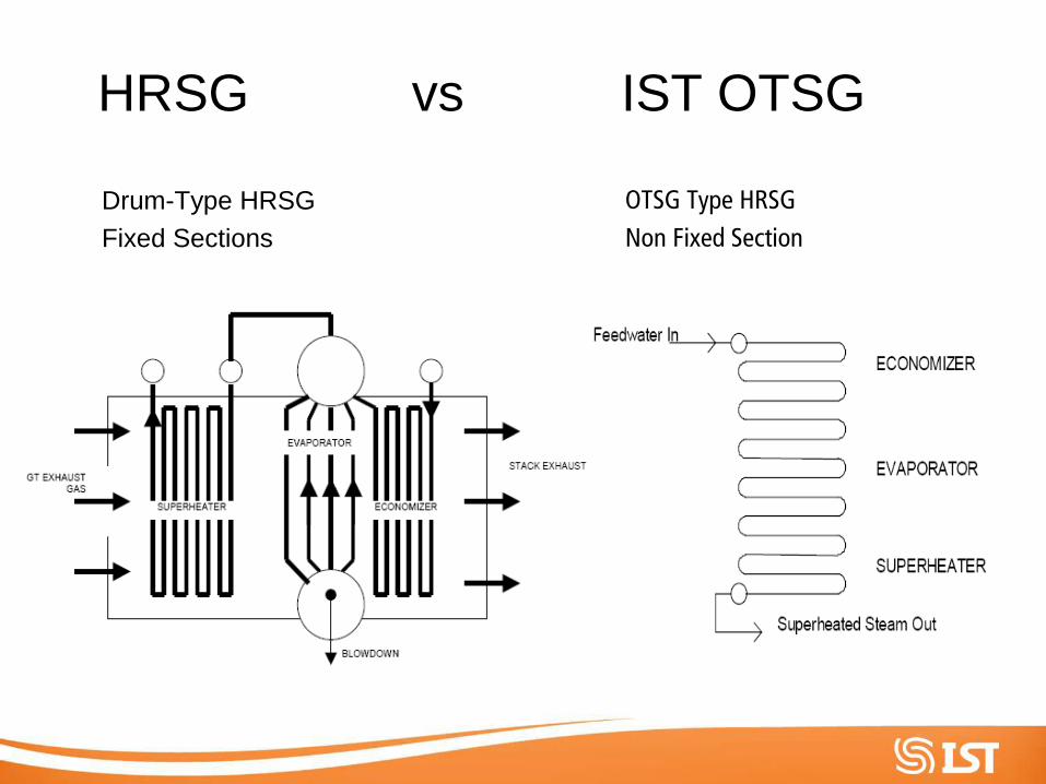
HRSG vs IST OTSG Drum-Type HRSG
Fixed Sections
OTSG Type HRSG
Non Fixed Section
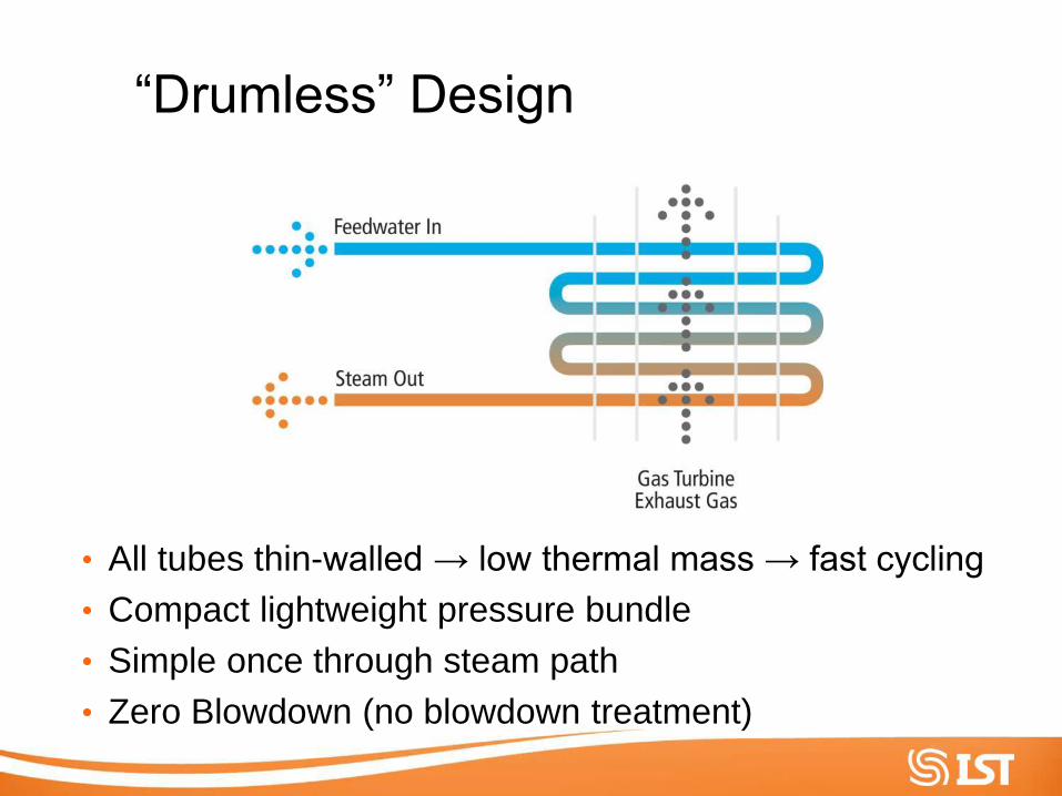
“Drumless” Design
• All tubes thin-walled → low thermal mass → fast cycling
• Compact lightweight pressure bundle
• Simple once through steam path
• Zero Blowdown (no blowdown treatment)
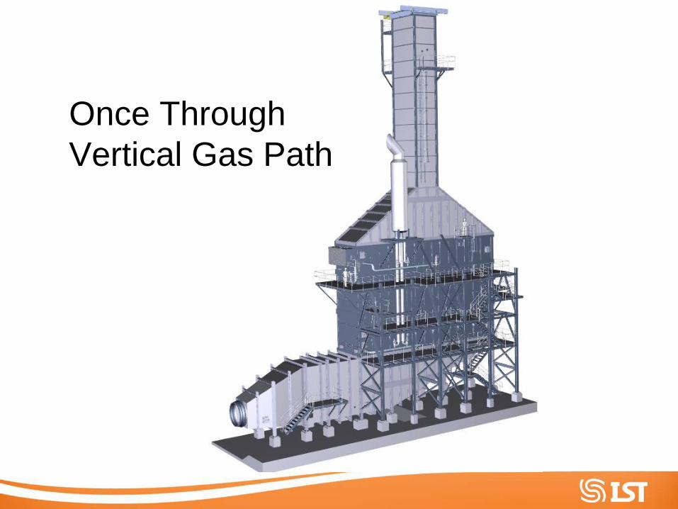
Once Through
Vertical Gas Path
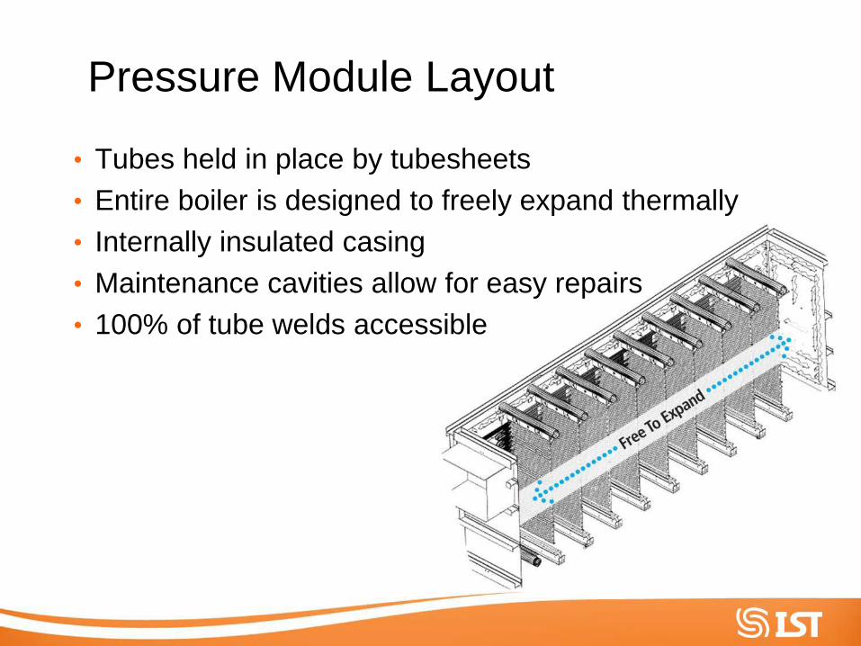
Pressure Module Layout
• Tubes held in place by tubesheets
• Entire boiler is designed to freely expand thermally
• Internally insulated casing
• Maintenance cavities allow for easy repairs
• 100% of tube welds accessible
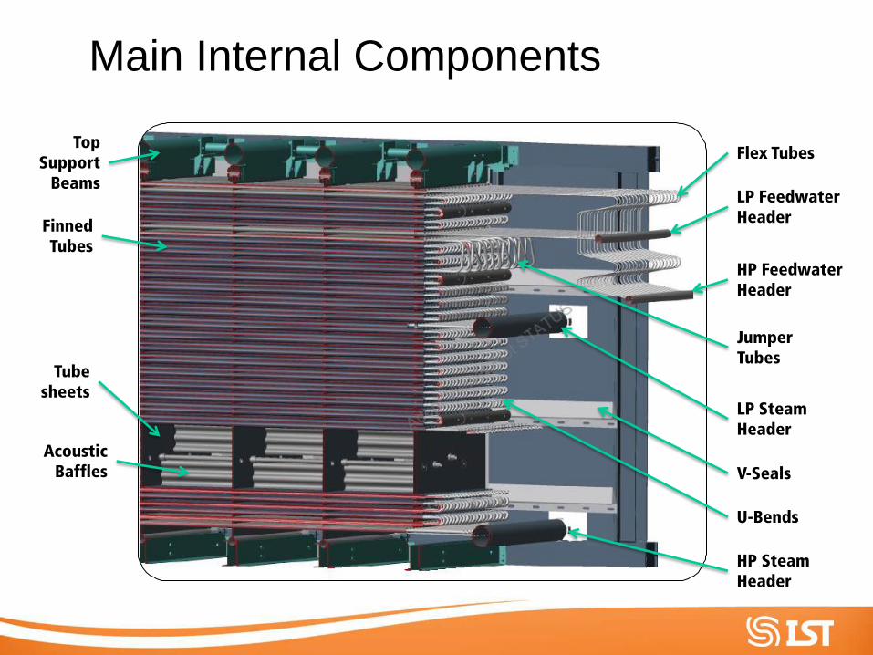
Main Internal Components
Flex Tubes
LP Feedwater Header
HP Feedwater Header
U-Bends
Top Support
Beams
LP Steam Header
HP Steam Header
Acoustic Baffles V-Seals
Tube sheets
Finned Tubes
Jumper Tubes
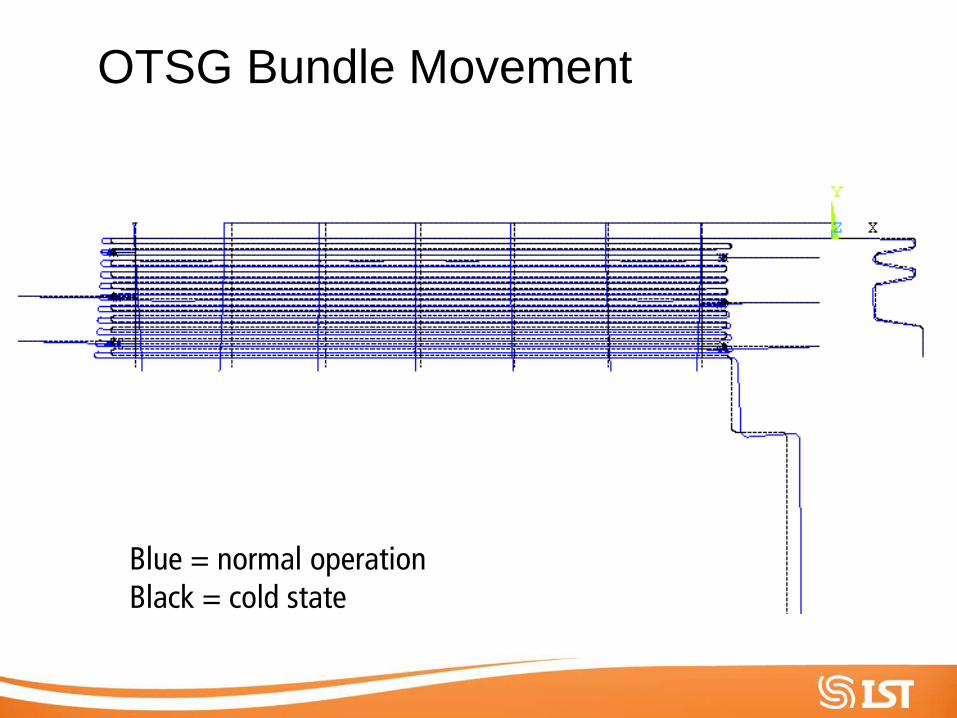
OTSG Bundle Movement
Blue = normal operation Black = cold state
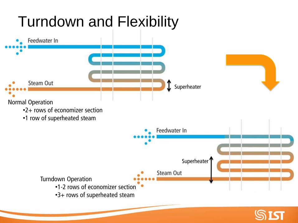
Turndown and Flexibility
Normal Operation •2+ rows of economizer section •1 row of superheated steam
Turndown Operation •1-2 rows of economizer section •3+ rows of superheated steam
Superheater
Superheater
Supplementary Firing
Supplementary Firing
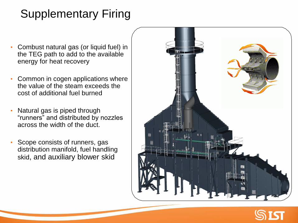
• Combust natural gas (or liquid fuel) in the TEG path to add to the available energy for heat recovery
• Common in cogen applications where the value of the steam exceeds the cost of additional fuel burned
• Natural gas is piped through “runners” and distributed by nozzles across the width of the duct.
• Scope consists of runners, gas distribution manifold, fuel handling
skid, and auxiliary blower skid
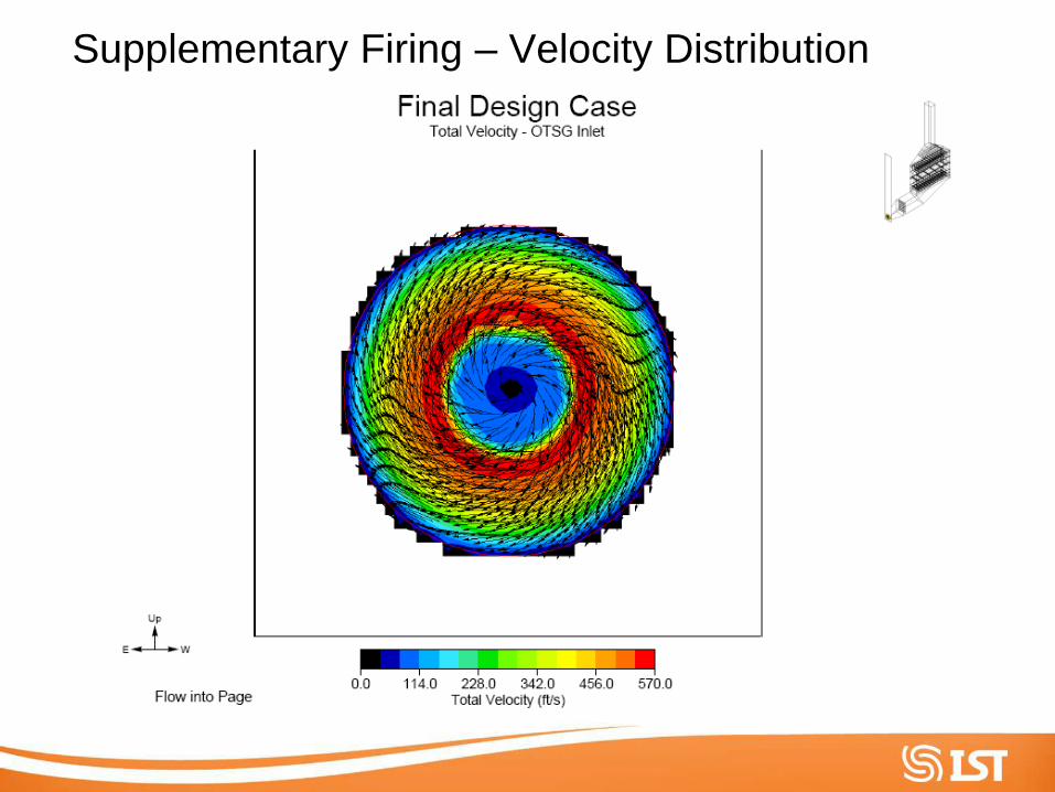
Supplementary Firing – Velocity Distribution
Supplementary Firing – Velocity Distribution
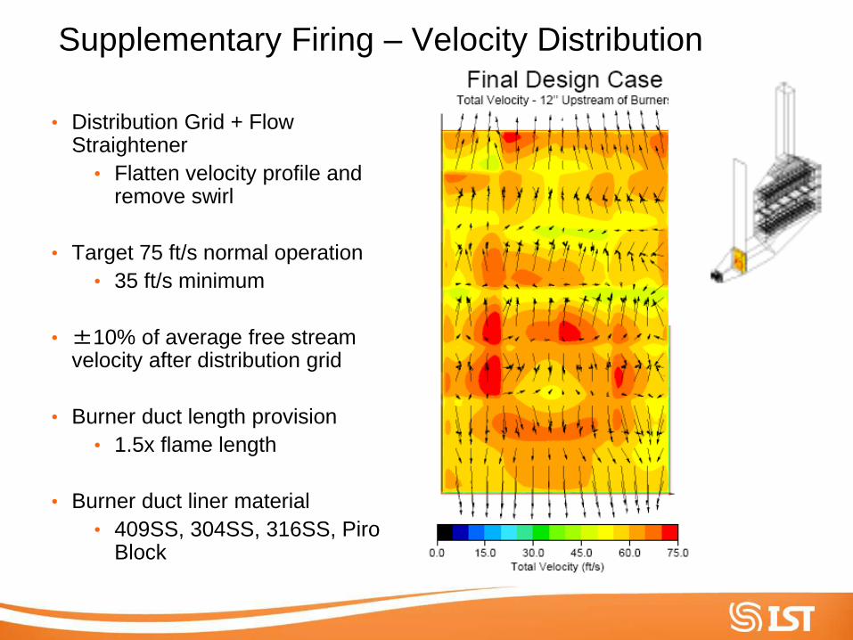
• Distribution Grid + Flow Straightener
• Flatten velocity profile and remove swirl
• Target 75 ft/s normal operation
• 35 ft/s minimum
• ±10% of average free stream velocity after distribution grid
• Burner duct length provision
• 1.5x flame length
• Burner duct liner material
• 409SS, 304SS, 316SS, Piro Block
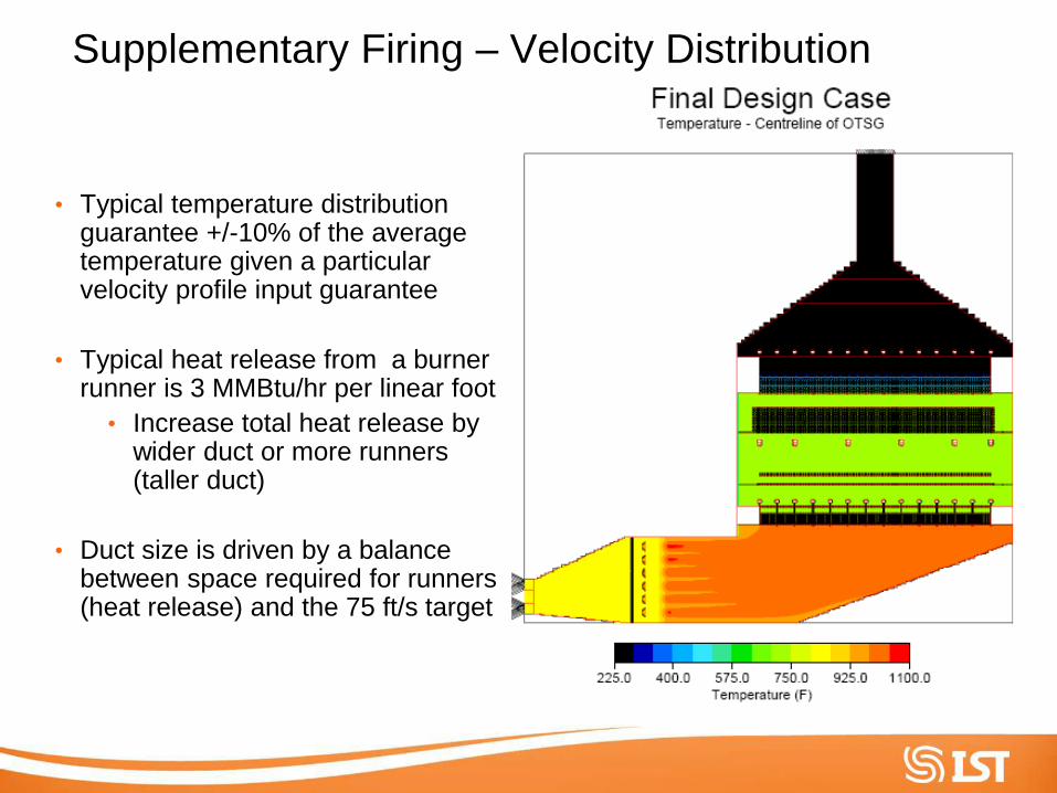
Supplementary Firing – Velocity Distribution
• Typical temperature distribution guarantee +/-10% of the average temperature given a particular velocity profile input guarantee
• Typical heat release from a burner runner is 3 MMBtu/hr per linear foot
• Increase total heat release by wider duct or more runners (taller duct)
• Duct size is driven by a balance between space required for runners (heat release) and the 75 ft/s target
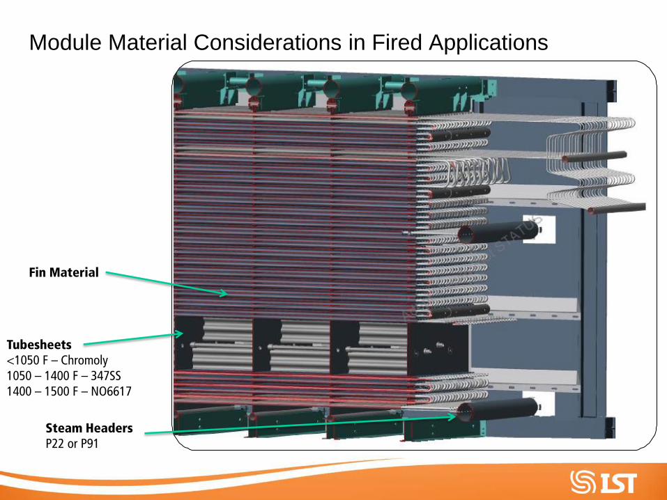
Module Material Considerations in Fired Applications
Tubesheets <1050 F – Chromoly 1050 – 1400 F – 347SS 1400 – 1500 F – NO6617
Steam Headers P22 or P91
Fin Material
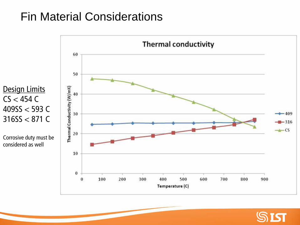
Fin Material Considerations
Design Limits CS < 454 C 409SS < 593 C 316SS < 871 C Corrosive duty must be considered as well
Fresh Air Firing – Case Study
Fresh Air Firing
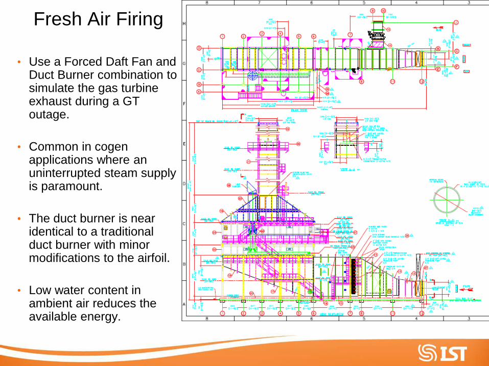
• Use a Forced Daft Fan and Duct Burner combination to simulate the gas turbine exhaust during a GT outage.
• Common in cogen applications where an uninterrupted steam supply is paramount.
• The duct burner is near identical to a traditional duct burner with minor modifications to the airfoil.
• Low water content in ambient air reduces the available energy.
Fresh Air Firing
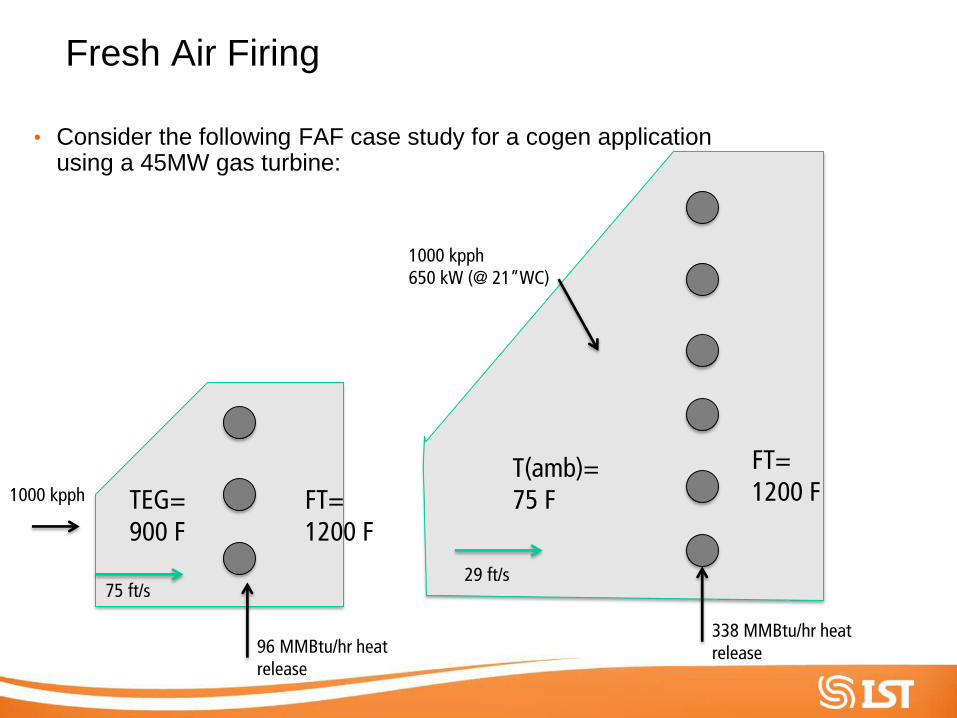
• Consider the following FAF case study for a cogen application using a 45MW gas turbine:
TEG= 900 F
FT= 1200 F
96 MMBtu/hr heat release
75 ft/s
FT= 1200 F
T(amb)= 75 F
29 ft/s
338 MMBtu/hr heat release
1000 kpph 650 kW (@ 21”WC)
1000 kpph
Fresh Air Firing
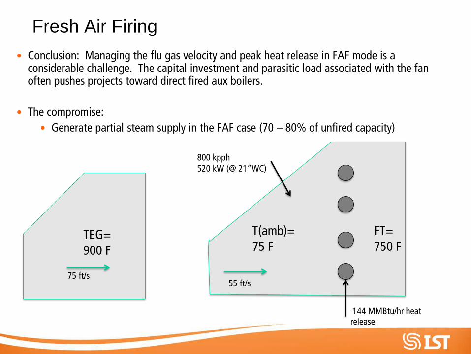
• Conclusion: Managing the flu gas velocity and peak heat release in FAF mode is a considerable challenge. The capital investment and parasitic load associated with the fan often pushes projects toward direct fired aux boilers.
• The compromise:
• Generate partial steam supply in the FAF case (70 – 80% of unfired capacity)
TEG= 900 F
FT= 750 F
T(amb)= 75 F
75 ft/s 55 ft/s
144 MMBtu/hr heat release
800 kpph 520 kW (@ 21”WC)

Balance of Plant Considerations
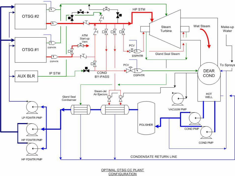
OPTIMAL STEAM LOOP B.o.P.:
1. Maintain Condensate Loop Vacuum during overnight
shutdowns (requires auxiliary boiler)
• Fastest start due to STG thermal gradient, gland steam, and water
chemistry
2. ST- Condenser should be spec’d for part load operation (larger
vacuum pumps)
• Allows gas removal from condensate in turndown modes
3. Dedicated ST Condenser By-passes
• Minimize water consumption during frequent starts and multi-unit
configurations
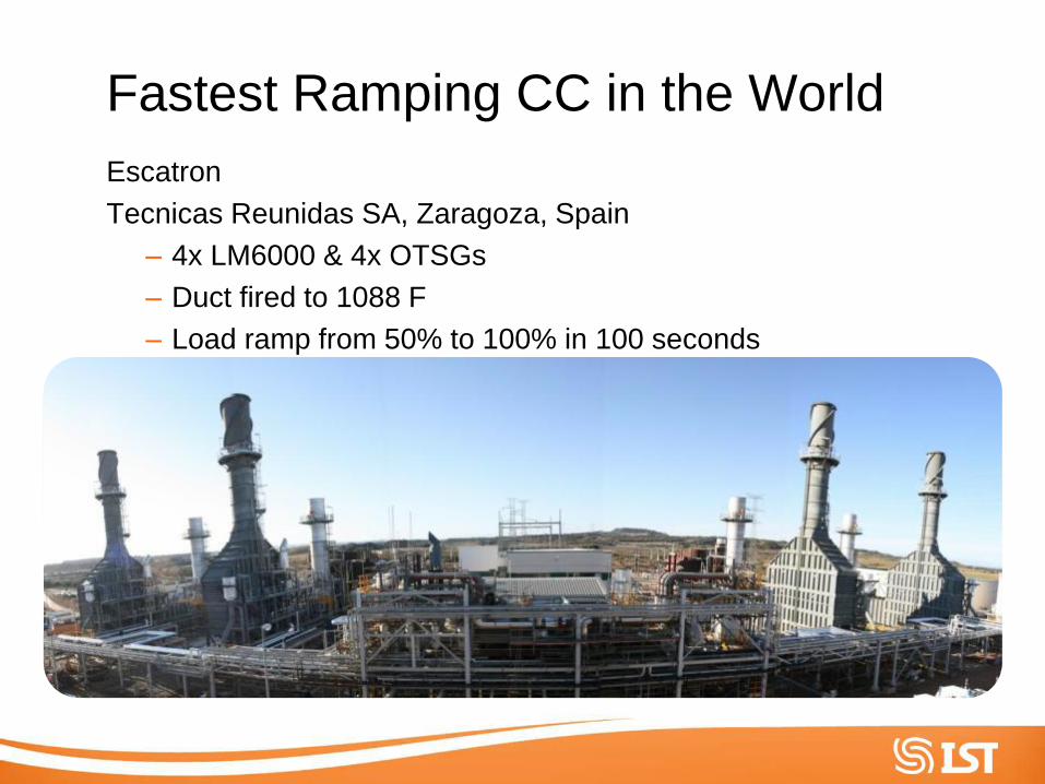
Fastest Ramping CC in the World
Escatron
Tecnicas Reunidas SA, Zaragoza, Spain
– 4x LM6000 & 4x OTSGs
– Duct fired to 1088 F
– Load ramp from 50% to 100% in 100 seconds – bers
Thank you for your time