Embed Size (px)
Citation preview

Federal Aviation Administration
HEAT RELEASE RATE
Updates
2015 February Materials Meeting
Huntington Beach, CA
Materials Working Group
Michael Burns, FAA Tech Center
February, 2015

AGENDA
Upper Pilot Burner Hot Surface Igniter
- Review handbook document for use in
today’s OSU’s
HR2 / OSU
- Test Data
- Chapter HR Updates
Next

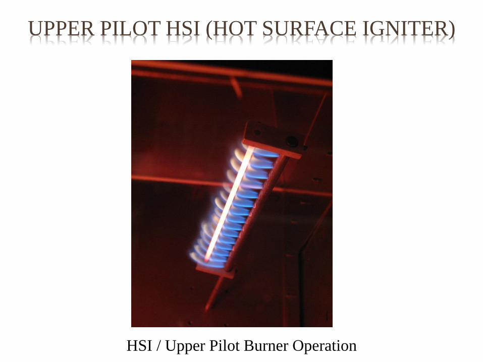
UPPER PILOT HSI (HOT SURFACE IGNITER)
• FAA Fire Test Handbook Version (OSU)
(Most likely Placed in Supplement Bullet 5.3.8)
• Optional Use (Much like the Drip Pan)
• Reduce variability within OSU heat release
units with regard to the performance of the
upper pilot burner
• Request Task Group Input

UPPER PILOT HSI (HOT SURFACE IGNITER)
-1.50
-1.00
-0.50
0.00
0.50
1.00
1.50
2.00
1 2 3 4 5 6
Mill
ivo
lts
Lab Code
Voltage Delta's (with HSI)
1 L/min
4 L/min
6 L/min
8 L/min
-0.3
-0.2
-0.1
0
0.1
0.2
0.3
0.4
0.5
0.6
0.7
1 2 3 4 5 6
(kW
/m2)/
mV
Lab Code
Cal. Factor Delta's (with HSI)
-1
-0.5
0
0.5
1
1.5
2
2.5
3
3.5
1 2 3 4 5 6
Mill
ivo
lts
Lab Code
Baseline mV Delta's (with HSI)
-0.16
-0.14
-0.12
-0.1
-0.08
-0.06
-0.04
-0.02
0
1 2 3 4 5 6W
/cm
2
Lab Code
Upper Corner Uniformity (with HSI)
Upper Left
Upper Right
UPPER PILOT HSI (HOT SURFACE IGNITER)
• It is critical that the upper pilot burner tube is not
moved out of position once set correctly.
• If the tube is inadvertently moved forward (towards
the globars) there is a chance that a large portion of
the upper pilot flames will go out entirely in the
presence of fire retardants whereas when in the
correct position only the flame tiplets will be
impacted while the material is burning off.
• The difference between the two conditions could
have a dramatic effect on the data.

UPPER PILOT HSI (HOT SURFACE IGNITER)
• In the event a material continues to impact the upper
pilot flames even with the burner tube in the correct
position an optional Hot Surface Igniter (HSI) may
be installed.
• Alternatively, the HSI may be installed and used for
all materials tested.
• If this device is installed, the center heat flux density
and 5% uniformity requirement must be verified
subsequent to a Methane gas calibration.

UPPER PILOT HSI (HOT SURFACE IGNITER)
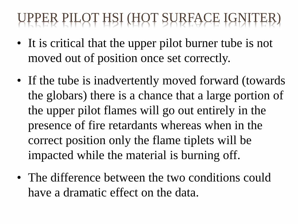
• A 0.125 ± 0.005 inch diameter stainless steel rod 8.0
± 0.0625 inches in length is positioned directly in
the flames of the upper pilot burner.
• The rod is continuously heated by the flamelets
acting as a hot surface igniter to auto-ignite any
upper pilot flames should they go out.
• The distance from the centerline of the burner tube
to the centerline of the HSI rod is 0.75 ± 0.125 inch.

UPPER PILOT HSI (HOT SURFACE IGNITER)
• Two stainless steel support brackets are mounted on
the upper pilot burner tube.
• The brackets are separated 8.0 ± 0.0625 inches from
each other (outer dimension) with one bracket
aligned flush with the closed end of the burner tube.
• Due to forced air flow through the chamber and
convection the upper pilot flames tend to curve
upward.
• To locate the HSI rod in the hottest portion of the
burner flames, the brackets are rotated upward 15 ±
5̊ on each end (Digital Protractor).

UPPER PILOT HSI (HOT SURFACE IGNITER)
• It is not necessary for each bracket to be at the same
angle provided the rod is in the direct flame path
across its entire length.
• Set screws secure the rod and brackets in position.
• The HSI rod must be cleaned or replaced when
showing signs of soot buildup or wear.
• Unless otherwise specified, dimensions are nominal
values in inches.
UPPER PILOT HSI (HOT SURFACE IGNITER)
Upper Pilot Burner HSI Rod and Brackets

UPPER PILOT HSI (HOT SURFACE IGNITER)
HSI Rod and Bracket Installation
UPPER PILOT HSI (HOT SURFACE IGNITER)
HSI / Upper Pilot Burner Operation

Federal Aviation Administration
Heat Release Rate Test Apparatus
February 2015
HR2 UPDATE

CHAPTER HR UPDATES
• Added “Burr-free holes , internally and externally, but not chamfered”
requirement to:
o Upper pilot burner holes (15)
o Lower Plate holes (8)
o Second Stage Plate holes (120)
• Range for Valid Calibration Factor must be 0.085 +/- 0.010 kW/mV
Removed all references to:
o Calibration Pass/Fail Criteria (5% STDEV): This is due to difficulties in
achieving this criteria now that the calibration factor is so small.
o Calibration Factor Term: (kW/m2)/mv
• Standardized use of sample holder drip pans.
o Required for all testing regardless of whether a material drips or not
o Optional: Permanently mounted to holder or removable

CHAPTER HR UPDATES
• For Stability (Heat Flux and Thermopile) :
o 5% STDEV requirement was lowered to 2% STDEV (5% was too easily
achieved while the system was still observed warming up).
o Added statement that center heat flux and thermopile are calculated
based on moving averages. (60 second moving average and 15 minute
moving average respectively).
Center Heat flux (60 second moving average)
Heat flux gauge millivolt signal that varies less than 2.0% standard deviation
over the last 60 seconds and having a calculated heat flux density that is
within range.
Chamber equilibrium (15 minute moving average)
Thermopile millivolt signal that varies less than 2.0% standard deviation
over the last 15 minutes commencing no sooner than 30 minutes after
turning the power to the globars on.

CHAPTER HR UPDATES
• Standardized Upper/Lower Pilot Gas Flow (Flow Meter Survey)
o Lower Pilot Flow Requirement:
Methane: 120 ± 5 mL/min (via panel mounted flow meter)
Air: 1.0 ± 0.2 L/min (via panel mounted flow meter)
o Upper Pilot Flow Requirement:
Methane: 1.5 ± 0.1 L/min (via HR2 calibration MFM/MFC)
Air: 1.0 ± 0.2 L/min (via panel mounted flow meter)
* All visual references in the document are aids in determining the correct
flame profile but the actual flow settings must be used (Photo’s added).
• Added caution statement that since drip pans are now required, if an electronic
igniter system is in place (lower pilot) it must not come in contact with the
sample holder drip pan when testing.
• Increased tolerance on airflow from 20 +/- 0.5 to 20 +/- 1 SCFM

Federal Aviation Administration
Heat Release Rate Test Apparatus
February 2015
48
56
50
99
85
52 48
51
45
100
84
52
0
20
40
60
80
100
120
Schneller 5596_36 5596_31 950_032 950_060 STD CC Panel
kW/m
2
Material ID
Peak Heat Release Rate
HR2
OSU
3% 1% 2% 4% 4% 4% 5% 3% 3% 1% 4% 1%
% Stdev (Repeatability)

Federal Aviation Administration
Heat Release Rate Test Apparatus
February 2015
46
25 28
50
97
47 47
27 28
51
97
51
0
20
40
60
80
100
120
Schneller 5596_36 5596_31 950_032 950_060 STD CC Panel
Seco
nd
s
Material ID
Time to Peak Heat Release Rate (seconds)
HR2
OSU
2% 5% 3% 2% 3% 1% 2% 12% 1% 0% 2% 2%
% Stdev (Repeatability)

Federal Aviation Administration
Heat Release Rate Test Apparatus
February 2015
37
47
55
37
31
37
40
52
59
42
33
38
0
10
20
30
40
50
60
70
Schneller 5596_36 5596_31 950_032 950_060 STD CC Panel
kW*m
in/m
2
Material ID
2-Minute Total Heat Release
HR2
OSU
2% 3% 1% 6% 0% 4% 4% 1% 4% 3% 1% 2%
% Stdev (Repeatability)

Federal Aviation Administration
Heat Release Rate Test Apparatus
February 2015
NEXT
• Assemble larger Focus Group RR comparing
HR2 (1) and Industry OSU’s (13)
• Develop and Distribute Test plan and materials
to participating labs
• Conduct RR Tests
• Reduce / Analyze Data for presenting at June
WG meeting
• Complete the HSI development Project
Federal Aviation Administration
Heat Release Rate Test Apparatus
February 2015
The Seattle Seahawks should:
A. Have given the ball to Marshawn
Lynch?
QUESTIONS?or presenting at June WG meeting

Federal Aviation Administration
Heat Release Rate Test Apparatus
February 2015
The Seattle Seahawks should:
A. Have given the ball to Marshawn
Lynch?
B. Fire the Offensive Coordinator?
QUESTIONS?or presenting at June WG meeting

Federal Aviation Administration
Heat Release Rate Test Apparatus
February 2015
The Seattle Seahawks should:
A. Have given the ball to Marshawn
Lynch?
B. Fire the Offensive Coordinator?
QUESTIONS?or presenting at June WG meeting