Embed Size (px)
Citation preview
14
Heat Transfer Analysis of Reinforced Concrete Beams Reinforced with GFRP Bars
Rami A. Hawileh American University of Sharjah
United Arab Emirates
1. Introduction
Corrosion of steel reinforcement has been identified as a key factor of deterioration and structural deficiency (Masoudi et al., 2011) in reinforced concrete (RC) structural members. The corrosion state of current RC bridges and high-rise buildings has been a source of concern to designers and engineers. In addition, such structures have been invulnerable to harsh environmental exposures, with little or no maintenance. Furthermore, such structures are experiencing larger amount of loads than their original capacities due to the increase number of users over the years (Bisby, 2003). Several different solutions were proposed to retrofit deteriorated structural members (Masoudi et al., 2011; Hawelih et al., 2011; Al-Tamimi et al., 2011) by replacing cracked concrete, using epoxy injected supplements, and FRP externally bonded systems. The use of embedded FRP bar reinforcement seems to be a promising solution (Masoudi et al., 2011; Bisby, 2003; Abbasi & Hogg, 2005; Abbasi & Hogg, 2006; Qu et al., 2009; Aiello & Ombres, 2002) to strengthen structural RC members in flexure and shear. Compared to the conventional reinforcing steel bars, the FRP bars seem to have a high strength to weight ratio, moderate modulus of elasticity and resistance to chemical and electrical corrosion. Although FRP materials were shown to have a brittle failure, due to their natural composition, still if designed properly they can show considerable amount of ductility (Rasheed et al, 2010; De Lorenzis & Teng, 2007). One of the draw backs of using FRP embedded bars is their low glass temperature and tendency to change state; from solid to liquid at elevated temperatures. Hence, the performance of FRP reinforced structural members under elevated temperatures draws many doubts and concerns and warrants further investigation. Few experimental tests have been conducted in the previous years on the fire performance of RC beams reinforced with FRP bars due to the high costs of such tests, tremendous amount of preparation, and shortage of specialized facilities (Franssen et al., 2009). Sadek et al. (Sadek et al., 2006) conducted a full scale experimental program on the fire resistance of RC beams reinforced with steel and Glass Fibre Reinforced Polymer (GFRP) bars. The test matrix composed of different reinforcing rebars used along with different concrete compressive strengths. The testing took place in a special testing facility and the beams were loaded statically at 60% of their ultimate load capacity during the course of the fire test. The tests followed the ASTM E119 (ASTM E119, 2002) standard and fire curve.
www.intechopen.com

Convection and Conduction Heat Transfer
300
Because of forming of flexure and shear cracks, fire was able to penetrate through the cross-section of the tested beams. The beams with low and normal strength concrete achieved a 30 and 45min fire endurance, respectively. On the other hand, the steel reinforced concrete beam achieved 90min fire endurance. The short fire endurance observed was mainly due to the small concrete cover used to protect the flexural reinforcements. Abbasi and Hogg (Abbasi & Hogg, 2006) conducted two full scale fire tests on RC beams reinforced with GFRP bars as the main reinforcement having a concrete cover of 75mm. The beams were fully loaded up to 40kN and subjected to the ISO 834 (ISO, 1975) fire standard curve. Eurocode 2 (Eurocode, 1992) and ACI-440 (ACI, 2008) procedures were used to design the beams. The beam reinforced with the steel stirrups achieved a 128min fire endurance while the beam reinforced with GFRP stirrups achieved a 94min fire endurance. Both RC beams limited the mid-span deflection to less than L/20; the deflection limit used in the load bearing capacity of BS 476: Part 20. In addition, the RC beams showed that they can pass the building regulations for fire safety by withstanding the fire test more than 90 min. Hawileh et al. (Hawileh et al., 2009, 2011) developed FE models that predicted the performance of RC beams strengthened with insulated carbon CFRP plates subjected to bottom and top fire loading. The models predicted with reasonable accuracy the experimental results of Williams et al. (Williams et al., 2008). It was concluded the developed models can serve as a valid alternative tool to expensive experimental testing especially in design oriented parametric studies, to capture the response of such beams when subjected to thermal loading. Different building codes recommend conducting further experimental and analytical research studies to investigate the thermal effect on RC members strengthened or reinforced with FRP sheets, plates or bars. Such studies would lead to a reduction on the tough restrictions and requirements set by the current codes of practice on the use of FRP materials in building and other types of structures. In addition, such studies would draw a better understanding on the behavior of FRP materials under fire actions that would enhance the available documentation and literature that in turn would encourage designers and engineers to use FRP bars more frequently to reinforce RC structural members. This chapter aims to develop a 3D nonlinear FE model that can accurately predict the temperature distribution at any location with RC beams reinforced with GFRP bars when exposed to the standard fire curve, ISO 834. The model is validated by comparing the predicted average temperature in the GFRP bars with the measured experimental data obtained by Abbasi and Hogg (Abbasi & Hogg, 2006). The developed FE model incorporates the different thermal nonlinear temperature dependant material properties associated with each material including density, specific heat, and thermal conductivity. Transient thermal analysis was carried out using the available FE code, ANSYS (ANSYS, 2007). The results of the developed FE model showed a good matching with the experimental results at all stages of fire loading. Several other observations and conclusion were drawn based on the results of the developed model.
2. Heat transfer equations
Heat transfers via the following three methods: Conduction, Convection, and Radiation. They can occur together or individually depending on the heat source exposure and environment. Conduction transfers heat within the RC beam by movement or vibrations of free electrons
www.intechopen.com
Heat Transfer Analysis of Reinforced Concrete Beams Reinforced with GFRP Bars
301
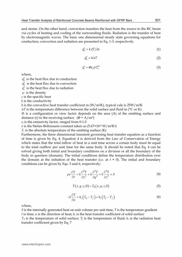
and atoms. On the other hand, convection transfers the heat from the source to the RC beam via cycles of heating and cooling of the surrounding fluids. Radiation is the transfer of heat by electromagnetic waves. The basic one dimensional steady state governing equations for conduction, convection and radiation are presented in Eq. 1-3, respectively.
kq k dT dx′′ = (1)
hq h T′′ = Δ (2)
4r t eq TΦε σ′′ = (3)
where,
kq′′ is the heat flux due to conduction
hq′′ is the heat flux due to convection
rq′′ is the heat flux due to radiation
ρ is the density c is the specific heat k is the conductivity h is the convective heat transfer coefficient in (W/m2K), typical vale is 25W/m2K ∆T is the temperature difference between the solid surface and fluid in (°C or K) Φ is a configuration or view factor depends on the area (A) of the emitting surface and distance (r) to the receiving surface. (Φ = A/πr2) εt is the emissivity factor, ranged from 0-1.0 σ is the Stefan-Boltzmann constant taken as (5.67×10⁻⁸ W/m2K4) Te is the absolute temperature of the emitting surface (K) Furthermore, the three dimensional transient governing heat transfer equation as a function of time is given by Eq. 4. Equation 4 is derived from the Law of Conservation of Energy which states that the total inflow of heat in a unit time across a certain body must be equal to the total outflow per unit time for the same body. It should be noted that Eq. 4 can be solved giving both initial and boundary conditions on a division or all the boundary of the body in question (domain). The initial conditions define the temperature distribution over the domain at the initiation of the heat transfer (i.e. at t = 0). The initial and boundary conditions can be given by Eqs. 5 and 6, respectively:
2 2 2
2 2 2
T T T Tc k k k S
t x y zρ ∂ ∂ ∂ ∂= + + +∂ ∂ ∂ ∂ (4)
( ) ( )0, , ,0 , , ,0T x y z T x y z= (5)
( ) ( )c S f r S f
Tk h T T h T T
u
∂− = − + −∂ (6)
where, S is the internally generated heat on unit volume per unit time; T is the temperature gradient t is time; u is the direction of heat; hc is the heat transfer coefficient of solid surface TS is the temperature of solid surface; Tf is the temperature of fluid; hr is the radiation heat transfer coefficient given by Eq. 7
www.intechopen.com
Convection and Conduction Heat Transfer
302
( )( )2 2
S fr S S fh T T T Tσε= + + (7)
where,
Sε is the emissivity of the surface in question
σ is the Stefan-Boltzmann constant 5.669 × 10⁻⁸ W/m2K4 (0.1714× 10⁻⁸ BTU/hr ft2 R4)
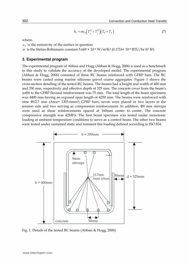
3. Experimental program
The experimental program of Abbasi and Hogg (Abbasi & Hogg, 2006) is used as a benchmark
in this study to validate the accuracy of the developed model. The experimental program
(Abbasi & Hogg, 2006) consisted of three RC beams reinforced with GFRP bars. The RC
beams were casted using marine siliceous gravel coarse aggregates. Figure 1 shows the
cross-section detailing of the tested RC beams. The beams had a height and width of 400 mm
and 350 mm, respectively and effective depth of 325 mm. The concrete cover from the beam’s
soffit to the GFRP flexural reinforcement was 75 mm. The total length of the beam specimens
was 4400 mm having an exposed span length of 4250 mm. The beams were reinforced with
nine Φ12.7 mm (Area= 1303.6mm2) GFRP bars, seven were placed in two layers at the
tension side and two serving as compression reinforcement. In addition, Φ9 mm stirrups
were used as shear reinforcements spaced at 160mm center to center. The concrete
compressive strength was 42MPa. The first beam specimen was tested under monotonic
loading at ambient temperature conditions to serve as a control beam. The other two beams
were tested under sustained static and transient fire loading defined according to ISO 834.
b = 350mm
h = 400mm
d = 325mm
9mmstirrups
50mm
50mm12.7mmmain rebars
concrete
Fig. 1. Details of the tested RC beams (Abbasi & Hogg, 2006)
www.intechopen.com
Heat Transfer Analysis of Reinforced Concrete Beams Reinforced with GFRP Bars
303
The fire testing was conducted at the building research establishment (Abbasi & Hogg, 2006). The internal dimensions of the furnace were 4000mm wide, 4000mm long and 2000mm deep. Each side of the furnace contained 10 burners lined in parallel to each other. The top side of the furnace is closed with either the test specimen, or lined with steel cover slabs. On the other hand, the furnace is lined with 1400 grade insulating brick to comply with British Standard and ISO 834 requirements.
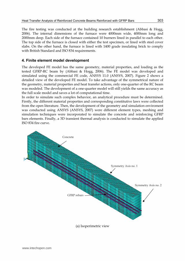
4. Finite element model development
The developed FE model has the same geometry, material properties, and loading as the tested GFRP-RC beam by (Abbasi & Hogg, 2006). The FE model was developed and simulated using the commercial FE code, ANSYS 11.0 (ANSYS, 2007). Figure 2 shows a detailed view of the developed FE model. To take advantage of the symmetrical nature of the geometry, material properties and heat transfer actions, only one-quarter of the RC beam was modeled. The development of a one-quarter model will still yields the same accuracy as the full scale model and saves a lot of computational time. In order to simulate such complex behavior, an analytical procedure must be determined. Firstly, the different material properties and corresponding constitutive laws were collected from the open literature. Then, the development of the geometry and simulation enviroment was conducted using ANSYS (ANSYS, 2007) were different element types, meshing and simulation techniques were incorporated to simulate the concrete and reinforcing GFRP bars elements. Finally, a 3D transient thermal analysis is conducted to simulate the applied ISO 834 fire curve.
GFRP rebars
Concrete
Symmetry Axis no. 2
Symmetry Axis no. 1
(a) Isoperimetric view
www.intechopen.com
Convection and Conduction Heat Transfer
304
Symmetry Axis no. 2
(b) Side view
Symmetry Axis no. 2
GFRP Bars
(c) Cross-sectional view
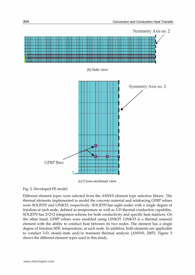
Fig. 2. Developed FE model
Different element types were selected from the ANSYS element type selection library. The
thermal elements implemented to model the concrete material and reinforcing GFRP rebars
were SOLID70 and LINK33, respectively. SOLID70 has eight nodes with a single degree of
freedom at each node, defined as temperature as well as 3-D thermal conduction capability.
SOLID70 has 2×2×2 integration scheme for both conductivity and specific heat matrices. On
the other hand, GFRP rebars were modeled using LINK33. LINK33 is a thermal uniaxial
element with the ability to conduct heat between its two nodes. The element has a single
degree of freedom SDF, temperature, at each node. In addition, both elements are applicable
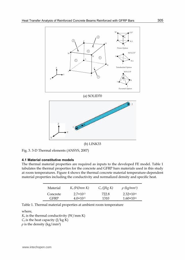
to conduct 3-D, steady-state and/or transient thermal analysis (ANSYS, 2007). Figure 3
shows the different element types used in this study.
www.intechopen.com
Heat Transfer Analysis of Reinforced Concrete Beams Reinforced with GFRP Bars
305
M O,P
I
N
K,L
J
M.N.O.P
M.N.O.P
Prism Option
I
K,L
J
Tetrahedral Option
IK
J
L
Pyramid Option
I
K
J
L
M
PO
N
X
Y
Z
1
2
3
4
5
6
(a) SOLID70
X
Y
Z
J
I
(b) LINK33
Fig. 3. 3-D Thermal elements (ANSYS, 2007)
4.1 Material constitutive models
The thermal material properties are required as inputs to the developed FE model. Table 1 tabulates the thermal properties for the concrete and GFRP bars materials used in this study at room temperatures. Figure 4 shows the thermal concrete material temperature-dependent material properties including the conductivity and normalized density and specific heat.
Material Ko (W/mm K) Co (J/kg K) ρ (kg/mm3)
Concrete 2.7×10⁻³ 722.8 2.32×10⁻⁶ GFRP 4.0×10⁻⁵ 1310 1.60×10⁻⁶
Table 1. Thermal material properties at ambient room temperature
where, Ko is the thermal conductivity (W/mm K) Co is the heat capacity (J/kg K)
ρ is the density (kg/mm3)
www.intechopen.com
Convection and Conduction Heat Transfer
306
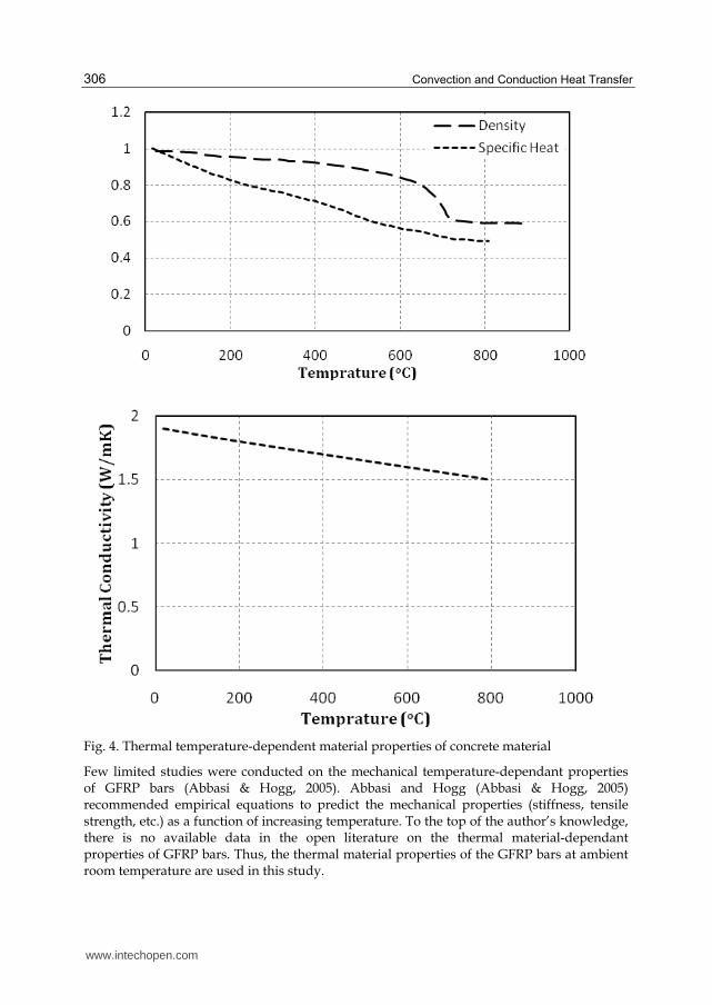
Fig. 4. Thermal temperature-dependent material properties of concrete material
Few limited studies were conducted on the mechanical temperature-dependant properties of GFRP bars (Abbasi & Hogg, 2005). Abbasi and Hogg (Abbasi & Hogg, 2005) recommended empirical equations to predict the mechanical properties (stiffness, tensile strength, etc.) as a function of increasing temperature. To the top of the author’s knowledge, there is no available data in the open literature on the thermal material-dependant properties of GFRP bars. Thus, the thermal material properties of the GFRP bars at ambient room temperature are used in this study.
www.intechopen.com
Heat Transfer Analysis of Reinforced Concrete Beams Reinforced with GFRP Bars
307
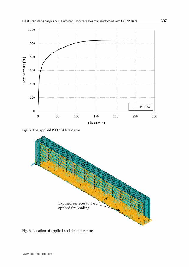
Fig. 5. The applied ISO 834 fire curve
Fig. 6. Location of applied nodal temperatures
Exposed surfaces to the applied fire loading
www.intechopen.com
Convection and Conduction Heat Transfer
308
4.2 Loading & boundary conditions
The developed FE model was exposed to thermal transient temperature-time curve, ISO834
(ISO, 1975). The applied ISO 834 fire curve is shown in Fig. 5. The ISO 834 curve was applied
as nodal temperature loading versus time at the soffit and vertical sides of the RC beam
specimen. The locations of the applied nodal transient temperatures are shown in Fig 6.
It must be noted that the applied nodal temperatures in the transient analysis domain
started at 200mm away from the edge of the RC beam to simulate the furnace boundary
conditions.
Since the fire nozzles in the furnace are very close to the tested RC beams, the author
applied the average furnace temperature directly to the soffit and sides of the developed FE
model (Hawileh et al., 2009, 2011). Thus, heat is transferred mainly by conduction in the
developed model. This approach resulted in good matching with the temperature results
recorded in the experimental program by Abbasi and Hogg (Abbasi & Hogg, 2006) and will
be discussed in the subsequent section.
The average furnace temperature was applied in terms of small time incremental steps. Each
time step is composed of several smaller sub-steps that are solved using Newton-Raphson’s
technique. In this study, automatic time stepping option is turned on to predict and control
time step sizes. At the end of each time (temperature) step, convergence is achieved by
Newton-Raphson equilibrium iterations when the temperature difference at each node from
each iteration to another is less than one degree.
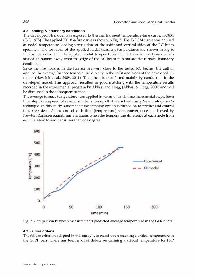
Fig. 7. Comparison between measured and predicted average temperature in the GFRP bars
4.3 Failure criteria
The failure criterion adopted in this study was based upon reaching a critical temperature in
the GFRP bars. There has been a lot of debate on defining a critical temperature for FRP
www.intechopen.com

Heat Transfer Analysis of Reinforced Concrete Beams Reinforced with GFRP Bars
309
bars. In this study, a critical temperature of 462°C in the GFRP is defined as the failure
criteria. Thus, the time to failure (fire endurance) of the RC beam specimen is defined when
the temperature in the GFRP bars reached 462°C during fire exposure. The same criteria is
used in the experimental program of Abbasi and Hogg (Abbasi & Hogg, 2006).
5. Results and discussions
5.1 Model validation
The predicted FE and experimental results were compared in order to validate the accuracy
of the developed model presented in this study. Figure 7 shows a comparison between the
predicted and measured average temperature of the GFRP bars during the course of fire
loading. The predicted average temperature in the GFRP bars is obtained every 0.5 second
time increment. It is clear from Fig. 7 that there is a good correlation between the predicted
and measured results throughout the entire thermal fire exposure. It should be noted from
Fig. 7 that the predicted average temperature results overestimates the temperature after 25
minutes of fire exposure. This slight deviation could be related to the lack of temperature-
dependant material properties of the GFRP bars. The tested RC beam failed approximately
after 128min of fire exposure, when the average temperature in the GFRP bars reached
462°C. Similarly, the predicted time to failure is 130 minutes. The percentage difference
between the FE model and experimental testing time to failure was 1.5%. Thus, the developed
model could serve as a valid numerical tool to predict the temperature distribution of RC
beams strengthened with GFRP bars when exposed to transient thermal loading.
5.2 Model behavior
The experimental programs are restricted to limited number of instrumentations
(thermocouples and strain gauges) due to their high cost and complex preparation. On the
contrary, full fields of temperature distribution at any location (node) within the beam could
predicted from the FE simulation of the validated model. Having a viable FE model, further
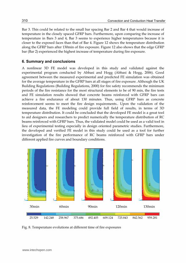
results can be extracted and used. For instance, Fig. 8 shows the temperature evolution
across the beam's cross section at different time periods of fire exposure. Figure 8 could be
used to determine the nodal temperature at any point (node) within the beam especially at
the GFRP bar reinforcement. As expected, the temperature evolution starts at the edges,
then propagate within the beam. It seems that the available concrete cover is sufficient to
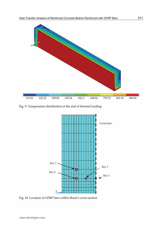
delay the increase of temperature at the GFRP reinforcement level up to 130min. Figure 9
shows the temperature distribution along the RC beam specimen at the end of fire. The FE
simulation can thus provide a wide range of results and the developed model could be used
as an alternative to the expensive experimental testing.
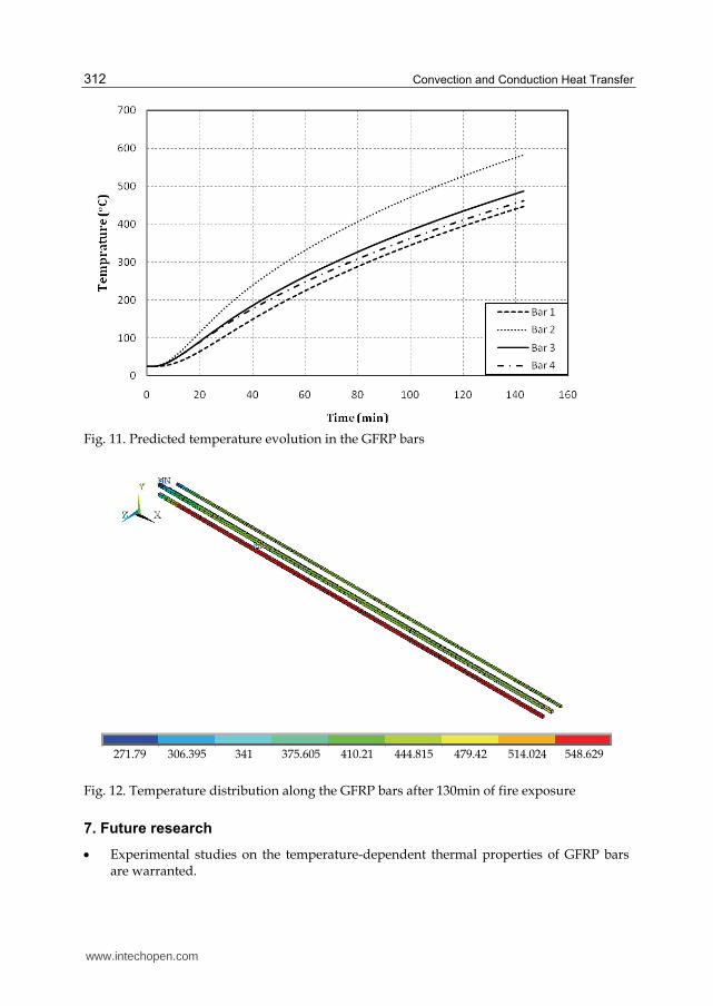
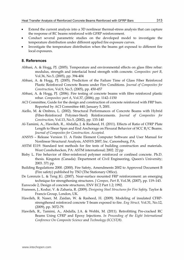
The experimental program lacked data on the increase of temperature in the individual
GFRP bars during the fire exposure. However, the FE model can predict the increase of
temperature at any specific location and time. Figures 10 and 11 shows the location of the
GFRP bars and temperature evolution in the individual bars at mid-span during fire
exposure. It is clear from Fig. 11 that the temperature rise in GFRP Bar 2 is the highest. This
is due to the application of the fire curve to the soffit and vertical side of the RC beam
specimen. Being located at the corner, Bar 2 thus has the shortest distance to the exposed
surfaces. Although Bars 1 and 3 seem to have the same perpendicular distance from the
exposed edge, the increase in temperature of Bar 1 seems to be slightly lower than that of
www.intechopen.com
Convection and Conduction Heat Transfer
310
Bar 3. This could be related to the small bar spacing Bar 2 and Bar 4 that would increase of
temperature in the closely spaced GFRP bars. Furthermore, upon comparing the increase of
temperature in Bars 3 and 4, Bar 3 seems to experience higher temperatures because it is
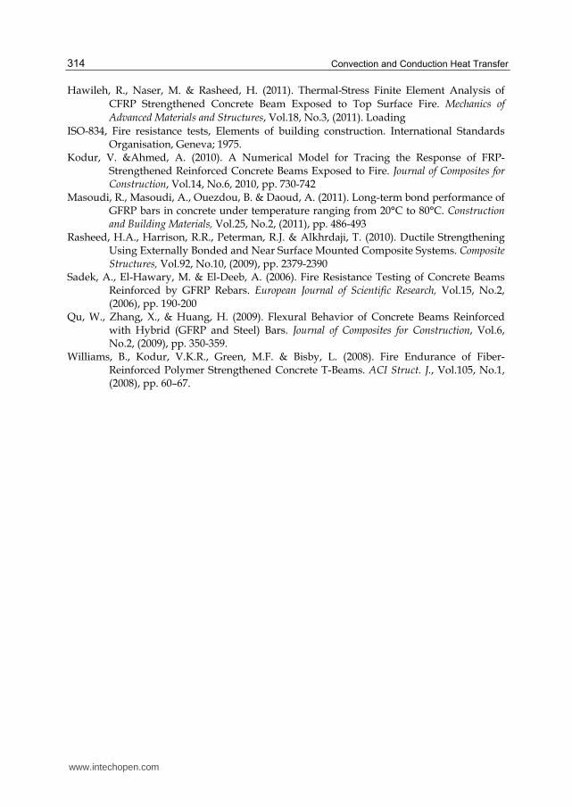
closer to the exposed faces than that of Bar 4. Figure 12 shows the temperature distribution
along the GFRP bars after 130min of fire exposure. Figure 12 also shows that the edge GFRP
bar (Bar 2) experienced the highest increase of temperature during fire exposure.
6. Summary and conclusions
A nonlinear 3D FE model was developed in this study and validated against the
experimental program conducted by Abbasi and Hogg (Abbasi & Hogg, 2006). Good
agreement between the measured experimental and predicted FE simulation was obtained
for the average temperature in the GFRP bars at all stages of fire exposure. Although the UK
Building Regulations (Building Regulations, 2000) for fire safety recommends the minimum
periods of the fire resistance for the most structural elements to be of 90 min, the fire tests
and FE simulation results showed that concrete beams reinforced with GFRP bars can
achieve a fire endurance of about 130 minutes. Thus, using GFRP bars as concrete
reinforcement seems to meet the fire design requirements.. Upon the validation of the
measured data, the FE modeling could provide full field of results, in terms of 3D
temperature distribution. It could be concluded that the developed FE model is a great tool
to aid designers and researchers to predict numerically the temperature distribution of RC
beams reinforced with GFRP bars. Thus, the validated model could be used as a valid tool in
lieu of experimental testing especially in design oriented parametric studies. Furthermore,
the developed and verified FE model in this study could be used as a tool for further
investigation of the fire performance of RC beams reinforced with GFRP bars under
different applied fire curves and boundary conditions.
30min 60min 90min 120min 130min
25.529 142.248 258.967 375.686 492.405 609.124 725.843 842.562 959.281
Fig. 8. Temperature evolutions at different time of fire exposures
www.intechopen.com
Heat Transfer Analysis of Reinforced Concrete Beams Reinforced with GFRP Bars
311
115.56 222.22 328.88 435.54 542.2 648.86 755.52 862.18 968.84
Fig. 9. Temperature distribution at the end of thermal loading
Bar
Bar
r 1
2
Bar
Ba
Cente
r 3
ar 4
erline
Fig. 10. Location of GFRP bars within Beam’s cross-section
www.intechopen.com
Convection and Conduction Heat Transfer
312
Fig. 11. Predicted temperature evolution in the GFRP bars
271.79 306.395 341 375.605 410.21 444.815 479.42 514.024 548.629
Fig. 12. Temperature distribution along the GFRP bars after 130min of fire exposure
7. Future research
• Experimental studies on the temperature-dependent thermal properties of GFRP bars are warranted.
www.intechopen.com
Heat Transfer Analysis of Reinforced Concrete Beams Reinforced with GFRP Bars
313
• Extend the current analysis into a 3D nonlinear thermal-stress analysis that can capture the response of RC beams reinforced with GFRP reinforcement.
• Conduct several parametric studies on the developed model to investigate the temperature distribution under different applied fire exposure curves.
• Investigate the temperature distribution when the beams get exposed to different fire local exposures.
8. References
Abbasi, A. & Hogg, PJ. (2005). Temperature and environmental effects on glass fibre rebar:
modulus, strength and interfacial bond strength with concrete. Composites: part B,
Vol.36, No.5, (2005), pp. 394-404
Abbasi, A. & Hogg, PJ. (2005). Prediction of the Failure Time of Glass Fiber Reinforced
Plastic Reinforced Concrete Beams under Fire Conditions. Journal of Composites for
Construction, Vol.9, No.5, (2005), pp. 450-457
Abbasi, A. & Hogg, PJ. (2006). Fire testing of concrete beams with fibre reinforced plastic
rebar. Composites: part A, Vol.37, (2006), pp. 1142–1150
ACI Committee, Guide for the design and construction of concrete reinforced with FRP bars.
Reported by ACI Committee 440; January 5, 2001.
Aiello, M. & Ombres, L. (2002). Structural Performances of Concrete Beams with Hybrid
(Fiber-Reinforced Polymer-Steel) Reinforcements. Journal of Composites for
Construction, Vol.13, No.5, (2002), pp. 133-140
Al-Tamimi, A., Hawileh, R., Abdalla, J. & Rasheed, H. (2011). Effects of Ratio of CFRP Plate
Length to Shear Span and End Anchorage on Flexural Behavior of SCC R/C Beams. Journal of Composites for Construction. Accepted.
ANSYS – Release Version 11. A Finite Element Computer Software and User Manual for
Nonlinear Structural Analysis, ANSYS 2007; Inc. Canonsburg, PA.
ASTM E119. Standard test methods for fire tests of building construction and materials.
West Conshohocken, PA: ASTM international; 2002. 22 pp
Bisby L. Fire behavior of fiber-reinforced polymer reinforced or confined concrete. Ph.D.
thesis. Kingston (Canada): Department of Civil Engineering, Queen's University;
2003. 371 pp.
Building Regulations 2000. (2000). Fire Safety, Amendments 2002 to Approved Document B
(Fire safety) published by TSO (The Stationary Office).
De Lorenzis L. & Teng JG. (2007). Near-surface mounted FRP reinforcement: an emerging
technique for strengthening structures. J Compos, Part B, Vol.38, (2007), pp. 119–143.
Eurocode 2, Design of concrete structures, ENV EC2 Part 1.2; 1992.
Franssen, J., Kodur, V. & Zaharia, R. (2009). Designing Steel Structures for Fire Safety. Taylor &
Francis Group, London, UK.
Hawileh, R. Naser, M. Zaidan, W. & Rasheed, H. (2009). Modeling of insulated CFRP-
strengthened reinforced concrete T-beam exposed to fire. Eng Struct, Vol.31, No.12,
(2009), pp. 3072-79.
Hawileh, R., Tamimi, A., Abdalla, J.A. & Wehbi, M. (2011). Retrofitting Pre-cracked RC
Beams Using CFRP and Epoxy Injections. In Proceeding of the Eight International
Conference On Composite Science and Technology (ICCST/8).
www.intechopen.com
Convection and Conduction Heat Transfer
314
Hawileh, R., Naser, M. & Rasheed, H. (2011). Thermal-Stress Finite Element Analysis of
CFRP Strengthened Concrete Beam Exposed to Top Surface Fire. Mechanics of
Advanced Materials and Structures, Vol.18, No.3, (2011). Loading
ISO-834, Fire resistance tests, Elements of building construction. International Standards Organisation, Geneva; 1975.
Kodur, V. &Ahmed, A. (2010). A Numerical Model for Tracing the Response of FRP-Strengthened Reinforced Concrete Beams Exposed to Fire. Journal of Composites for Construction, Vol.14, No.6, 2010, pp. 730-742
Masoudi, R., Masoudi, A., Ouezdou, B. & Daoud, A. (2011). Long-term bond performance of GFRP bars in concrete under temperature ranging from 20°C to 80°C. Construction and Building Materials, Vol.25, No.2, (2011), pp. 486-493
Rasheed, H.A., Harrison, R.R., Peterman, R.J. & Alkhrdaji, T. (2010). Ductile Strengthening Using Externally Bonded and Near Surface Mounted Composite Systems. Composite Structures, Vol.92, No.10, (2009), pp. 2379-2390
Sadek, A., El-Hawary, M. & El-Deeb, A. (2006). Fire Resistance Testing of Concrete Beams Reinforced by GFRP Rebars. European Journal of Scientific Research, Vol.15, No.2, (2006), pp. 190-200
Qu, W., Zhang, X., & Huang, H. (2009). Flexural Behavior of Concrete Beams Reinforced with Hybrid (GFRP and Steel) Bars. Journal of Composites for Construction, Vol.6, No.2, (2009), pp. 350-359.
Williams, B., Kodur, V.K.R., Green, M.F. & Bisby, L. (2008). Fire Endurance of Fiber-Reinforced Polymer Strengthened Concrete T-Beams. ACI Struct. J., Vol.105, No.1, (2008), pp. 60–67.
www.intechopen.com
Convection and Conduction Heat TransferEdited by Dr. Amimul Ahsan
ISBN 978-953-307-582-2Hard cover, 394 pagesPublisher InTechPublished online 17, October, 2011Published in print edition October, 2011
InTech EuropeUniversity Campus STeP Ri Slavka Krautzeka 83/A 51000 Rijeka, Croatia Phone: +385 (51) 770 447 Fax: +385 (51) 686 166www.intechopen.com
InTech ChinaUnit 405, Office Block, Hotel Equatorial Shanghai No.65, Yan An Road (West), Shanghai, 200040, China
Phone: +86-21-62489820 Fax: +86-21-62489821
The convection and conduction heat transfer, thermal conductivity, and phase transformations are significantissues in a design of wide range of industrial processes and devices. This book includes 18 advanced andrevised contributions, and it covers mainly (1) heat convection, (2) heat conduction, and (3) heat transferanalysis. The first section introduces mixed convection studies on inclined channels, double diffusive coupling,and on lid driven trapezoidal cavity, forced natural convection through a roof, convection on non-isothermal jetoscillations, unsteady pulsed flow, and hydromagnetic flow with thermal radiation. The second section coversheat conduction in capillary porous bodies and in structures made of functionally graded materials, integraltransforms for heat conduction problems, non-linear radiative-conductive heat transfer, thermal conductivity ofgas diffusion layers and multi-component natural systems, thermal behavior of the ink, primer and paint,heating in biothermal systems, and RBF finite difference approach in heat conduction. The third sectionincludes heat transfer analysis of reinforced concrete beam, modeling of heat transfer and phasetransformations, boundary conditions-surface heat flux and temperature, simulation of phase changematerials, and finite element methods of factorial design. The advanced idea and information described herewill be fruitful for the readers to find a sustainable solution in an industrialized society.
How to referenceIn order to correctly reference this scholarly work, feel free to copy and paste the following:
Rami A. Hawileh (2011). Heat Transfer Analysis of Reinforced Concrete Beams Reinforced with GFRP Bars,Convection and Conduction Heat Transfer, Dr. Amimul Ahsan (Ed.), ISBN: 978-953-307-582-2, InTech,Available from: http://www.intechopen.com/books/convection-and-conduction-heat-transfer/heat-transfer-analysis-of-reinforced-concrete-beams-reinforced-with-gfrp-bars