Embed Size (px)
Citation preview

HAL Id: hal-02865305https://hal.archives-ouvertes.fr/hal-02865305
Submitted on 9 Apr 2021
HAL is a multi-disciplinary open accessarchive for the deposit and dissemination of sci-entific research documents, whether they are pub-lished or not. The documents may come fromteaching and research institutions in France orabroad, or from public or private research centers.
L’archive ouverte pluridisciplinaire HAL, estdestinée au dépôt et à la diffusion de documentsscientifiques de niveau recherche, publiés ou non,émanant des établissements d’enseignement et derecherche français ou étrangers, des laboratoirespublics ou privés.
Heat Transfer and Adhesion Study for the FFF AdditiveManufacturing Process
Arthur Lepoivre, Nicolas Boyard, Arthur Levy, Vincent Sobotka
To cite this version:Arthur Lepoivre, Nicolas Boyard, Arthur Levy, Vincent Sobotka. Heat Transfer and Adhesion Studyfor the FFF Additive Manufacturing Process. 23rd International Conference on Material Forming,ESAFORM 2020, May 2020, Cottbus, Germany. pp.948-955, �10.1016/j.promfg.2020.04.291�. �hal-02865305�

Available online at www.sciencedirect.com
ScienceDirect
Procedia Manufacturing 00 (2019) 000–000 www.elsevier.com/locate/procedia
2351-9789 © 2020 The Authors. Published by Elsevier Ltd.
This is an open access article under the CC BY-NC-ND license https://creativecommons.org/licenses/by-nc-nd/4.0/)
Peer-review under responsibility of the scientific committee of the 23rd International Conference on Material Forming.
23rd International Conference on Material Forming (ESAFORM 2020)
Heat Transfer and Adhesion Study for the
FFF Additive Manufacturing Process
Arthur Lepoivrea,b *, Nicolas Boyarda, Arthur Levya, Vincent Sobotkaa
a Université de Nantes, CNRS, Laboratoire de thermique et énergie de Nantes, LTeN, UMR 6607, F-44000 Nantes, France b Institut de Recherche Technologique Jules Verne,44340 Bouguenais, France
* Corresponding author: [email protected]
Abstract
Additive manufacturing is becoming more and more important today by offering very advantageous opportunities. It gives the ability to
manufacture parts with complex geometry, without the need of specific tools. This work focuses on fused filament fabrication process. It
consists in melting the polymer, and extruding it through a nozzle to create a structure defined by a toolpath. The extruded filament solidifies
while cooling.
One of the major drawbacks of this process is the poor mechanical properties of the parts compared to thermoplastic injection. This is related
to (i) the porosities between deposited filaments and (ii) the limited adhesion between deposited layers. This adhesion phenomenon is
thermally driven by the molecular mobility of the polymer chains. The objective of this work is to understand, model and quantify heat
exchanges in the process, in order to define the process window leading to optimal mechanical resistance of the parts.
With this aim, a laboratory-scale instrumented 3D printing machine has been designed and manufactured. This bench is thermally controlled.
Polymer and environment temperatures can be measured with an infrared camera, pyrometer and thermocouples instrumentation. In parallel,
a numerical model has been developed to predict the influence of the process parameters on the cooling and adhesion. For this purpose,
thermal properties have been characterized. A sensitivity analysis quantifies the most relevant properties to measure and control accurately
and a comparison between numerical and experimental results validates the approach.
© 2020 The Authors. Published by Elsevier Ltd.
This is an open access article under the CC BY-NC-ND license https://creativecommons.org/licenses/by-nc-nd/4.0/)
Peer-review under responsibility of the scientific committee of the 23rd International Conference on Material Forming.
Keywords: additive manufacturing ; Fused Filament Fabrication ; heat transfer ; adhesion ; infrared measurement
1. Introduction
Additive manufacturing, or 3D printing, is the generic term
for several material processes, such as Fused Filament
Fabrication (FFF), StereoLithogrAphy (SLA) or Selective
Laser Melting (SLM). According to the Wohlers Report 2019
[1], all additive manufacturing products and services would
represent $15.8 billion revenue in 2020 and $35.6 billion in
2024. This work focuses on the FFF process that has a lot of
applications in aeronautic, automotive, health and prototyping
industries. In this process, 3D parts are manufactured by
extruding a melted thermoplastic filament through a nozzle.
The toolpath of the nozzle is previously designed by software
in order to create the part. The filament is heated by the
extrusion unit that brings the polymer in a viscous or molten
state. After deposition, the filament cools down with its
environment and solidifies, allowing the addition of new
layers. This process offers advantage of producing parts with
complex geometry, with a wide choice of materials without
requiring the use of a molding cavity. However, this process
has several drawbacks: (a) the size of the manufactured parts
are limited, (b) the manufacturing time remains long (c) the

2 L/ Procedia Manufacturing 00 (2019) 000–000
mechanical properties are lower compared to parts produced
with other processes as injection for example. This work
focuses on this poor mechanical trade-off.
At the macroscopic scale, in order to achieve a good
adhesion, it is necessary to find the compromise about the
adequate processing temperatures (air temperature inside the
printing atmosphere and nozzle temperature). As illustrated in
Fig. 1, the temperature must be high enough to develop a
sufficient interface healing of the filaments. But this
temperature should not be too high to avoid structure collapse
because of low viscosity or thermal degradation/chemical
aging of the extruded polymer. To find precisely the limit of
this optimal processing area, the thermal history needs to be
predicted accurately.
Fig. 1. Polymer printability rules for FFF process.
At the filament scale, the decrease of mechanical properties
is due (i) to the macro-porosities inside the part due to the
circular shape of the filaments and (ii) to the poor adhesion at
the interface of adjacent filaments.
(i) Macro-porosities: This first phenomenon can be
associated to the coalescence of two polymer spheres as
described by Frenkel’s model [2], [3] and analytical solutions
were proposed for cylinders [4]–[6]. Frenkel’s model has been
used in the literature by authors working on additive
manufacturing process [7]–[13]. The coalescence process is
described by the angle of coalescence in degree 𝜃 , which
follows the evolution rate:
𝑑𝜃
𝑑𝑡=
𝜎(𝑇)
𝑎0∙𝜇(𝑇)∙2−5 3⁄ cos(𝜃) sin(𝜃)∙(2−cos(𝜃))1 3⁄
(1−cos(𝜃))∙(1+cos(𝜃))1 3⁄ (1)
where σ is the surface tension in N/m; a0the initial radius of the
cylinder in m; μ the viscosity in Pa.s and T the temperature of
the polymer in K. Note that surface tension and viscosity are
two thermally dependent properties.
(ii) Adhesion: The second phenomenon can be empirically
defined by the reptation theory by De Gennes [14]. It has been
studied in the polymer processing literature [15], [16] and can
be modeled by the degree of healing Dh, which evolution rate
follows:
Dh(t) = (t
tR(𝑇))1 4⁄
(2)
where 𝑡𝑅 is the temperature dependent reptation time of the
polymer, which can be identified with a rheological study.
Coalescence and reptation phenomena are both thermally-
driven, through the variation of the temperature dependent
properties (surface tension 𝜎 , viscosity 𝜇 and reptation time
𝑡𝑅). It justifies the importance to predict the accurate thermal
history of the polymer during its printing. This is the aim of the
present work.
There are several heat transfers phenomena during the FFF
process, as illustrated in Fig. 2: (1) heat brought by the extruder,
often with a heating resistance, (2) convective cooling of the
filament with the air, (3) heat exchanges between the adjacent
filaments, (4) heat brought by the support plate, (5) radiative
losses and (6) heat source from the exothermal crystallization
for semi-crystalline polymers.
Fig. 2. At least 6 different heat transfer
phenomena are identified in the FFF process.
In the 90’s, heat transfer in the FFF process was studied in
the literature, with a 1D analytical model and 2D numerical
model by Yardimci [17], [18] and was used to predict filament
temperature evolution [8], [12]. In 2000 and 2003, Rodriguez
and Thomas proposed a 2D analytical model [19], [20]. These
two models were compared with experimental data
(thermocouple between two layers) by Sun et al. [7] in Fig. 3.
Fig. 3. (a) Comparison of the heat transfer model existing in the literature of
FFF process and (b) geometry for the 2D analytical model. Adapted from [7].
The 1D analytical model seems to over-estimate the
experimental temperature evolution, but has the good trend.
The 2D analytical model ( 𝑦 = 4𝐻 for the last filament
extruded) seems to best fit the measurements, but only after
0.5s. For information, the glass transition 𝑇𝑔 of ABS is also
plotted in the figure. Adhesion develops while temperature is
above 𝑇𝑔.
Some authors modelled the deformation of the extruded
filament [13], [21]–[24]. It appears to be very temperature
dependent. This work will focus on accurate prediction of
adhesion and heat transfer.

Author name / Procedia Manufacturing 00 (2019) 000–000 3
The final objective of the work consists in describing and
controlling FFF process with high temperature material, more
specifically PEKK material reinforced or not with short carbon
fibers, for aeronautic applications. The experimental
development was developed initially on ABS, for its greater
ease of implementation.
In order to understand and quantify the heat transfer and
adhesion phenomena during the FFF process, two methods are
used. First, an experimental bench has been designed and
fabricated, with the objective to measure the temperature field
of the polymer during its printing with infrared (IR)
technology. The second method is a simulation model
developed with COMSOL Multiphysics® v5.4 to predict
temperature evolution and degree of healing.
2. Methodology
2.1. Instrumented bench
Fig. 4. Experimental bench showing the heated chamber for 3D printing of
high temperature polymers and the infrared camera for temperature
measurements.
Bench description:
The experimental bench is a modified commercial 3D-
printer CR-10 from Creality3D, based on the open-source
Prusa i3 structure, as shown in Fig. 4. The main issue is to
measure the temperature in situ at the scale of a single filament
(~1mm), during the part fabrication. With the perspective of
studying high performance thermoplastic (PAEK family), the
commercial printer was upgraded to reach the temperature
levels for this polymer family: up to 400°C.
A 500W heating plate system was built, to reach plate
temperature around 250°C. The extruder was changed, for full-
metal unit, with a water-cooling closed circuit system. A closed
insulated chamber maintains the part in a 200°C atmosphere. It
does not block the three translation moving system of the 3D-
printer inside the chamber. Electronics and mechanical parts
are kept outside the chamber. This heating chamber is
mandatory for printing polymers like PEKK.
Temperature measurements:
Thermal instrumentation consists in an infrared camera
SC7500 InSb from FLIR and a modified pyrometer
PYROSPOT DPE 10M from DIAS Infrared Systems. PEKK
material was characterized to determine its emissivity versus
wavelength. The pyrometer and IR camera wavelengths were
chosen accordingly and operate both within the wavelength
range 3.7 – 5.1 µm. FTIR spectrometer was used, on the 1.4-
17.9 µm wavelength range, with KBr separator, LN MCT Mid
2x2mm detector and golden integrating sphere at ambient
temperature. Complementary work performed by another team
in the project indicated the absence of thermal influence on the
emissivity, for a fixed wavelength. We supposed the same
constant behavior for the wavelengths we use for IR
measurement technology. Absorbance was deduced after
measurement of normal-hemispheric transmittance and
reflectance.
Additionally, the smallest target size for commercial
pyrometer is ∅𝑝𝑦𝑟𝑜𝑚𝑒𝑡𝑒𝑟 = 0.6 𝑚𝑚. Thus, we had to adapt the
bench, and use a bigger nozzle, which was 𝜙𝑛𝑜𝑧𝑧𝑙𝑒 = 1 𝑚𝑚,
than usual in the additive manufacturing process.
Procedure:
A simple geometry was 3D-printed part in ABS and PEKK:
a 60x2.2x50 mm wall part, with a single filament in the
thickness along the z-axis, as illustrated in Fig. 5.
Obviously, IR camera and pyrometers devices need to be
kept out of the printing chamber because of the temperature
level. Two infrared transparent windows made of CaF2 are
positioned on the side and the top of the chamber. Qualitative
measurements were performed with infrared camera for ABS,
without temperature determination because calibration was not
performed for the used objective yet. Quantitative
measurements were given by the pyrometer for ABS and
PEKK. Polymer emissivity were taken as 𝜀 = 0.91 for ABS as
reported in the literature [25] and 𝜀 = 0.94 for PEKK,
measured from spectroscopy characterization over the
adequate wavelength range. The measurement device was
pointing normal to the wall length as indicated in Fig. 5:
Fig. 5. Experimental set-up. A single filament wall was 3D printed. The
pyrometer measures the temperature from the side in situ.
2.2. Heat transfer modeling for FFF process
Let’s consider the domain Ω represented in Fig. 6. In this
domain, heat transfer equations can be described by the
following set of equations.

4 L/ Procedia Manufacturing 00 (2019) 000–000
Fig. 6. Geometry and boundary conditions used in the heat transfer model.
In 𝛀 domain:
𝜌𝐶𝑝 (𝜕𝑇
𝜕𝑡+ 𝒖 ∙ 𝜵𝑇) = 𝛻 ∙ (𝒌 ∙ 𝜵𝑇) + 𝑄crystallization (3)
where 𝜌 is the density, Cp the specific heat, 𝑢 the polymer
velocity and 𝒌 the conductivity tensor and 𝑄crystallization a
source term for the crystallization effects.
Boundary condition on :
A heat transfer coefficient models the convection cooling:
−𝑘�⃗� T ∙ �⃗� = hconvection ∙ (𝑇 − 𝑇𝑐ℎ𝑎𝑚𝑏𝑒𝑟) (4)
with ℎ𝑐𝑜𝑛𝑣𝑒𝑐𝑡𝑖𝑜𝑛 the convection heat transfer coefficient, the
radiative effects are neglected.
Interface conditions:
Thermal contact resistances (TCR) are assumed on all the
internal boundaries. Thus the heat flux through these
boundaries writes:
−𝑘�⃗� T ∙ �⃗� =1
𝑇𝐶𝑅𝑓𝑖𝑙𝑎𝑚𝑒𝑛𝑡 \𝑧
(𝑇+ − 𝑇−) on
−𝑘�⃗� T ∙ �⃗� =1
𝑇𝐶𝑅𝑓𝑖𝑙𝑎𝑚𝑒𝑛𝑡 \𝑦
(𝑇+ − 𝑇−) on
−𝑘�⃗� T ∙ �⃗� =1
𝑇𝐶𝑅𝑠𝑢𝑝𝑝𝑜𝑟𝑡(𝑇+ − 𝑇−) on
(5)
(6)
(7)
where 𝑇+ and 𝑇− are the temperatures on both sides of the
interface.
Initial conditions:
At initial time, the temperature in each domain is supposed
to be known and uniform:
𝑇(𝑡 = 0) = 𝑇𝑒𝑥𝑡𝑟𝑢𝑠𝑖𝑜𝑛 on the polymer just extruded
𝑇(𝑡 = 0) = 𝑇𝑓𝑖𝑙𝑎𝑚𝑒𝑛𝑡𝑠 on the previously extruded
filaments
𝑇(𝑡 = 0) = 𝑇𝑠𝑢𝑝𝑝𝑜𝑟𝑡 on the support plate
(8)
(9)
(10)
As long as the exothermal enthalpy of the crystallization is
low, this term can be neglected, with Δ𝐻𝑐𝑟𝑦𝑠𝑡𝑎𝑙𝑙𝑖𝑧𝑎𝑡𝑖𝑜𝑛 < 40 𝐽 ∕
𝑔 for PEKK [26] and with no crystallization for ABS
(amorphous). Moreover, the thermal conductivity of the
material �̿� is considered as constant, but it can be anisotropic
for fiber reinforced material. As there is not fluid flow inside
the extruded filament, so 𝑢 = 0.
From the equation (3) and with these assumptions, the
simplified heat transfer in 3D can be written:
𝜕𝑇
𝜕𝑡=
𝑘𝑥
𝜌𝐶𝑝
𝜕2𝑇
𝜕𝑥2 +𝑘𝑦
𝜌𝐶𝑝
𝜕2𝑇
𝜕𝑦2 +𝑘𝑧
𝜌𝐶𝑝
𝜕2𝑇
𝜕𝑧2 (11)
The diffusion term in the x direction can also be neglected
such that the problem reduces to a 2D model. In order to check
the accuracy of this simplification, a dimensional analysis is
performed, for a filament of length 𝐿𝑥, width 𝐿𝑦 and thickness
𝐿𝑧. Dimensionless variables are defined as:
𝑇∗ =𝑇−𝑇𝑐ℎ𝑎𝑚𝑏𝑒𝑟
𝑇𝑒𝑥𝑡𝑟𝑢𝑠𝑖𝑜𝑛−𝑇𝑐ℎ𝑎𝑚𝑏𝑒𝑟
𝑥∗ =𝑥
𝐿𝑥 ; 𝑦∗ =
𝑦
𝐿𝑦 ; 𝑧∗ =
𝑧
𝐿𝑧 ; 𝑡∗ =
𝑡
𝜏𝑐
[𝑇∗; 𝑥∗; 𝑦∗; 𝑧∗] 𝜖 [0; 1] ; 𝑡∗𝜖[0; +∞]
(12)
(13)
(14)
Three Fourier numbers 𝐹𝑜𝑥 , 𝐹𝑜𝑦 and 𝐹𝑜𝑧 are then
introduced. They characterize the ratio between the
conductivity term over the inertia term, and take into account a
characteristic time on the order of magnitude 𝜏𝐶 = 1𝑠 ,
corresponding to the process time:
𝐹𝑜𝑖 =𝑘𝑖
𝜌𝐶𝑝∙
𝜏𝑐
𝐿𝑖 2
With 𝑖 = 𝑥, 𝑦 or 𝑧 (15)
The dimensionless heat-transfer equation is obtained as:
𝜕𝑇∗
𝜕𝑡∗ = 𝐹𝑜𝑥𝜕2𝑇∗
𝜕𝑥∗2 + 𝐹𝑜𝑦𝜕2𝑇∗
𝜕𝑦∗2 + 𝐹𝑜𝑧𝜕2𝑇∗
𝜕𝑧∗2 (16)
Very early during the printing, the length of the filament 𝐿𝑥
becomes much larger than the filament section dimensions 𝐿𝑦
and 𝐿𝑧. Thus:
𝐹𝑜𝑥 ≪ 𝐹𝑜𝑦 𝑎𝑛𝑑 𝐹𝑜𝑥 ≪ 𝐹𝑜𝑧 (17)
As a matter of fact, usually in printed parts, 𝐿𝑦 > 𝐿𝑧 .
Therefore, the condition becomes:
𝑡 > √10𝑘𝑥
𝑘𝑦∙
𝐿𝑦
𝑣𝑝𝑟𝑖𝑛𝑡𝑖𝑛𝑔∼ 0.01𝑠 (18)
Where vprinting is the printing velocity, the condition Fox <
0.1 Foy < 0.1 Foz is fulfilled.
Under these assumptions, the heat transfer equation reduces
to:
𝜕𝑇∗
𝜕𝑡∗ = 𝐹𝑜𝑦𝜕2𝑇∗
𝜕𝑦∗2 + 𝐹𝑜𝑧𝜕2𝑇∗
𝜕𝑧∗2
(19)
With our process parameters, this condition is achieved after
0.01 seconds of extrusion. It validates a 2D description:
𝜕𝑇
𝜕𝑡=
𝑘𝑦
𝜌𝐶𝑝
𝜕2𝑇
𝜕𝑦2 +𝑘𝑧
𝜌𝐶𝑝
𝜕2𝑇
𝜕𝑧2
(20)
Author name / Procedia Manufacturing 00 (2019) 000–000 5
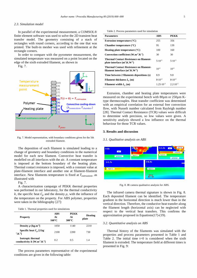
2.3. Simulation model
In parallel of the experimental measurement, a COMSOL®
finite element software was used to solve the 2D transient heat
transfer model. The geometry consisting of a stack of
rectangles with round corners, according to the one that was
printed. The built-in mesher was used with refinement at the
rectangle corners.
In order to compare with the pyrometer measurement, the
simulated temperature was measured on a point located on the
edge of the sixth extruded filament, as shown in
Fig. 7.
Fig. 7. Model representation, with boundary conditions given for the 5th
extruded filament.
The deposition of each filament is simulated leading to a
change of geometry and boundary conditions in the numerical
model for each new filament. Convective heat transfer is
modelled on all interfaces with the air. A constant temperature
is imposed at the bottom boundary of the heating plate.
Thermal contact resistance is imposed, with a constant value at
plate-filament interface and another one at filament-filament
interface. New filaments temperature is fixed at 𝑇extrusion, as
illustrated with
Fig. 7.
A characterization campaign of PEKK thermal properties
was performed in our laboratory, for the thermal conductivity
𝑘, the specific heat 𝐶𝑝 and the density 𝜌, with the influence of
the temperature on the property. For ABS polymer, properties
were taken in the bibliography [27]:
Table 1. Thermal properties used for simulations
Property
ABS
At
160°C
PEKK
At
300°C
Heating
plate
Density 𝝆 [kg.m-3] 1050 1140 2210
Specific heat 𝑪𝒑 [J.kg-
1.K-1] 2100 2200 730
Isotropic thermal
conductivity 𝒌 [W.m-1.K-1] 0.2 0.5 1.4
The process parameters representative of the experimental
conditions are given in the following table:
Table 2. Process parameters used for simulation
Parameters ABS PEKK
Extrusion temperature (°C) 255 356
Chamber temperature (°C) 95 139
Heating plate temperature (°C) 100 160
Convection coefficient (W.m-2.K-1) 30 30
Thermal Contact Resistance on filament-
plate interface (m2.K.W-1) 5∙10-5 5∙10-5
Thermal Contact Resistance on filament-
filament interface (m2.K.W-1) 10-4 10-4
Time between 2 filaments depositions (s) 8.9 9.8
Filament thickness 𝑳𝒛 (m) 8∙10-4 8∙10-4
Filament width 𝑳𝒚 (m) 1.25∙10-3 2.2∙10-3
Extrusion, chamber and heating plate temperatures were
measured on the experimental bench with 80µm or 250µm K-
type thermocouples. Heat transfer coefficient was determined
with an empirical correlation for an external free convection
flow, with Nusselt number calculated from Rayleigh number
[28]. Thermal Contact Resistance (TCR) values were difficult
to determine with precision, so low values were given. A
sensitivity analysis showed a low influence on the thermal
behaviour for those TCR values.
3. Results and discussion
3.1. Qualitative analysis on ABS
Fig. 8. IR camera qualitative analysis for ABS.
The infrared camera thermal signature is shown in Fig. 8.
Each deposited filament can be identified. The temperature
gradient in the horizontal direction is much lower than in the
vertical direction. Therefore, the conductive heat transfer along
the filament length (horizontal axis) can be neglected with
respect to the vertical heat transfers. This confirms the
approximation proposed in Equations(17)-(19).
3.2. Quantitative analysis on ABS
Thermal history of the filaments was simulated with the
properties and process parameters presented in Table 1 and
Table 2. The initial time t=0 is considered when the sixth
filament is extruded. The temperature field at different times is
presented in Fig. 9:
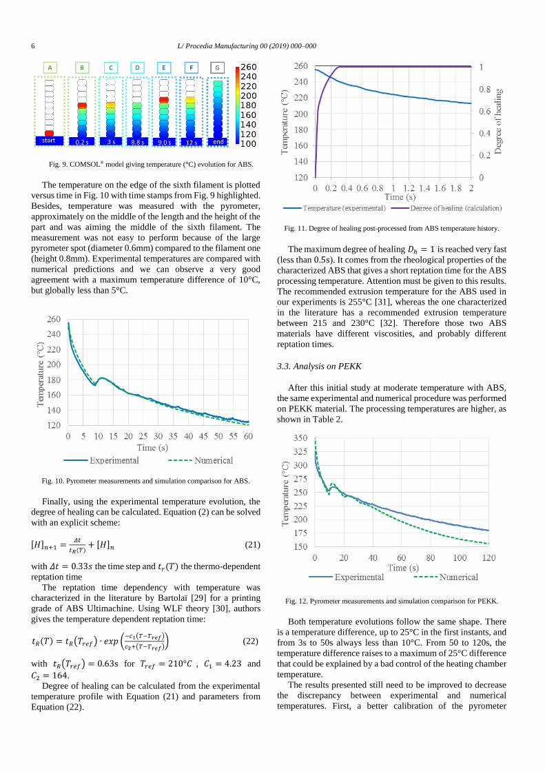
6 L/ Procedia Manufacturing 00 (2019) 000–000
Fig. 9. COMSOL® model giving temperature (°C) evolution for ABS.
The temperature on the edge of the sixth filament is plotted
versus time in Fig. 10 with time stamps from Fig. 9 highlighted.
Besides, temperature was measured with the pyrometer,
approximately on the middle of the length and the height of the
part and was aiming the middle of the sixth filament. The
measurement was not easy to perform because of the large
pyrometer spot (diameter 0.6mm) compared to the filament one
(height 0.8mm). Experimental temperatures are compared with
numerical predictions and we can observe a very good
agreement with a maximum temperature difference of 10°C,
but globally less than 5°C.
Fig. 10. Pyrometer measurements and simulation comparison for ABS.
Finally, using the experimental temperature evolution, the
degree of healing can be calculated. Equation (2) can be solved
with an explicit scheme:
[𝐻]𝑛+1 =𝛥𝑡
𝑡𝑅(𝑇)+ [𝐻]𝑛 (21)
with 𝛥𝑡 = 0.33𝑠 the time step and 𝑡𝑟(𝑇) the thermo-dependent
reptation time
The reptation time dependency with temperature was
characterized in the literature by Bartolaï [29] for a printing
grade of ABS Ultimachine. Using WLF theory [30], authors
gives the temperature dependent reptation time:
𝑡𝑅(𝑇) = 𝑡𝑅(𝑇𝑟𝑒𝑓) ∙ 𝑒𝑥𝑝 (−𝑐1(𝑇−𝑇𝑟𝑒𝑓)
𝑐2+(𝑇−𝑇𝑟𝑒𝑓)) (22)
with 𝑡𝑅(𝑇𝑟𝑒𝑓) = 0.63s for 𝑇𝑟𝑒𝑓 = 210°𝐶 , 𝐶1 = 4.23 and
𝐶2 = 164.
Degree of healing can be calculated from the experimental
temperature profile with Equation (21) and parameters from
Equation (22).
Fig. 11. Degree of healing post-processed from ABS temperature history.
The maximum degree of healing 𝐷ℎ = 1 is reached very fast
(less than 0.5s). It comes from the rheological properties of the
characterized ABS that gives a short reptation time for the ABS
processing temperature. Attention must be given to this results.
The recommended extrusion temperature for the ABS used in
our experiments is 255°C [31], whereas the one characterized
in the literature has a recommended extrusion temperature
between 215 and 230°C [32]. Therefore those two ABS
materials have different viscosities, and probably different
reptation times.
3.3. Analysis on PEKK
After this initial study at moderate temperature with ABS,
the same experimental and numerical procedure was performed
on PEKK material. The processing temperatures are higher, as
shown in Table 2.
Fig. 12. Pyrometer measurements and simulation comparison for PEKK.
Both temperature evolutions follow the same shape. There
is a temperature difference, up to 25°C in the first instants, and
from 3s to 50s always less than 10°C. From 50 to 120s, the
temperature difference raises to a maximum of 25°C difference
that could be explained by a bad control of the heating chamber
temperature.
The results presented still need to be improved to decrease
the discrepancy between experimental and numerical
temperatures. First, a better calibration of the pyrometer

Author name / Procedia Manufacturing 00 (2019) 000–000 7
associated with PEKK radiative properties would improve the
experimental measurements. And secondly, the simulation may
be improved by taking into account temperature-dependent
thermal properties and convective heat transfer coefficient.
Also, more precise determination of the thermal contact
resistance should be carried out.
In order to calculate the degree of healing, PEKK
rheological parameters were characterized from another PEKK
material grade [33]. The degree of healing is calculated using
the experimental temperature evolution and is shown versus
time in Fig. 13. It becomes constant after 40 s and is equal to
0.45.
There is an important difference between ABS and PEKK
material for FFF process. For ABS, the full healing is reached
very fast during the cooling of the filament as shown in Fig. 11.
For PEKK, the maximum degree of healing is never reached
with the printing conditions usedFig. 13. This shows the
importance to characterize accurately the thermo-dependent
reptation time of the polymer, and to use a precise prediction
of the thermal history undergone by the printed filament. This
analysis would determine the process window for a specified
material, as shown in Fig. 1.
Fig. 13. Degree of healing calculated from PEKK temperature history.
4. Conclusion
This paper aims at predicting the heat transfer and the
adhesion behavior during the printing of polymer filament with
FFF process. As shown in Fig. 1, temperature history of the
filament is the key-element to determine. An experimental
instrumented bench was designed and manufactured. It gives in
situ temperature evolution of the filament. A numerical twin
was developed and simulates the transient heat transfer at the
filament scale. The calculated temperature field was then post-
processed to predict the degree of adhesion.
There is a good adequacy between temperature measured
with the pyrometer, and temperature calculated with the
COMSOL model. Because of the poor knowledge of the
rheological properties, the calculated degree of healing was
found to be equal to 1 very quickly for ABS. However, this is
the opposite for PEKK material, which reaches only a degree
of healing of 0.45 after the cooling-down of the filament.
The bench was designed to handle high temperature and
future work will consist in studying deposition of PEKK more
precisely, and also for carbon fibers reinforced PEKK with
different process parameters.
The short-term perspectives are to use the model with the
thermo-dependent thermal properties, which were
characterized in the LTeN laboratory on PEKK polymer.
Moreover, measurements with the calibrated IR camera need to
be performed on the PEKK material. Also, others perspectives
would be to study the coalescence evolution in order to predict
the macro-porosities formation in the FFF parts production.
With those two steps, the coalescence and the healing, a global
degree of adhesion would be calculable. This would give
precious information about the process window of the FFF
process, with high performance composites used for
aeronautics applications.
Acknowledgment
This study is part of the FACT project managed by IRT Jules
Verne (French Institute in Research and Technology in
Advanced Manufacturing Technologies for Composite,
Metallic and Hybrid Structures). The authors wish to associate
the industrial and academic partners of this project,
respectively AIRBUS, ARKEMA, DAHER, DEDIENNE,
EOS, LIEBHERR, SAFRAN, ZODIAC Engineering, CANOE,
TOBECA, LTeN, PIMM, CNRS, ENSAM and Université de
Nantes.
The authors want to thank Gwenaël BIOTTEAU and
Nicolas LEFEVRE from the technical service of LTeN
laboratory, for their help in the experimental bench design and
fabrication.
References
[1] Wohlers TT, Campbell I, Diegel O, Huff R, Kowen J, Wohlers Report
2019. 2019.
[2] Frenkel J, Viscous Flow of Crystalline Bodies under the Action of Surface
Tension. J Phys (USSR) 1945; 9(5): 385-91.
[3] Pokluda O, Bellehumeur CT, Machopoulos J, Modification of Frenkel ’ s
Model for Sintering. AIChE J 1997; 43, (12): 3253–56.
[4] Hopper RW, Coalescence of Two Viscous Cylinders by Capillarity: Part I,
Theory. Am Ceram Soc J 1993; 76(12): 2947–52.
[5] Hopper RW, Coalescence of Two Equal Cylinders: Exact Results for
Creeping Viscous Plane Flow Driven by Capillarity. Am Ceram Soc J
1984; 67(12): C262–4.
[6] Defauchy D, Simulation du procédé de fabrication directe de pièces
thermoplastiques par fusion laser de poudre. PhD thesis 2013, Arts et
métiers ParisTech, France.
[7] Sun Q, Rizvi GM, Bellehumeur CT, Gu P, Effect of processing conditions
on the bonding quality of FDM polymer filaments. Rapid Prototyp J 2008;
14(2): 72–80.
[8] Bellehumeur C, Li L, Modeling of Bond Formation Between Polymer
Filaments in the Fused Deposition Modeling Process. J Manuf Process
2004; 6(2): 170–8.
[9] Kazmer DO, A Protocol for Filament Production and Use in Fused
Deposition Modeling. SPE Antec 2016, 881–6.
[10] Faes M, Ferraris E, Moens D, Influence of Inter-layer Cooling time on the
Quasi-static Properties of ABS Components Produced via Fused
Deposition Modelling. Procedia CIRP 2016; 42: 748–53.
[11] Brenken B, Barocio E, Favaloro A, Kunc V, Pipes RB, Fused filament
fabrication of fiber-reinforced polymers: A review. Addit Manuf 2018;
21: 1–16.
[12] Li L, Sun Q, Bellehumeur C, Gu P, Investigation of bond formation in
FDM process. Solid Free Fabr Proc 2002; 400–7.
[13] Shahriar BB, Chabert F, Nassiet V, Cantarel A, Garnier C, Toward
improvement of the properties of parts manufactured by FFF (fused
filament fabrication) through understanding the influence of temperature
and rheological behaviour on the coalescence phenomenon. AIP
Conference Proceedings 2017; 1896: 040008-1-6.

8 L/ Procedia Manufacturing 00 (2019) 000–000
[14] de Gennes PG, Reptation of a Polymer Chain in the Presence of Fixed
Obstacles. J Chem Phys 1971; 55(2): 572–9.
[15] Wool RP, Yuan B‐L, McGarel OJ, Welding of polymer interfaces. Polym
Eng Sci 1989; 29(19): 1340–67.
[16] Yang F, Pitchumani R, Healing of thermoplastic polymers at an interface
under nonisothermal conditions. Macromolecules 2002; 35(8): 3213–24.
[17] Yardimci MA, Güçeri S, Conceptual framework for the thermal process
modelling of fused deposition. Rapid Prototyp J 1996; 2(2): 26–31.
[18] Yardimci MA, Danforth S, A phenomenological numerical model for
fused deposition processing of particle filled parts. Solid Free Fabr Proc
1995: 189–95.
[19] Thomas JP, Rodriguez JF, Modeling the Fracture Strength Between
Fused-Deposition Extruded Roads. Solid Free Fabr Proc 2000: 17–23.
[20] Rodríguez JF, Thomas JP, Renaud JE, Mechanical behavior of
acrylonitrile butadiene styrene fused deposition materials modeling.
Rapid Prototyp J 2003; 9(4): 219–30.
[21] Shahriar BB, Cantarel A, Chabert F, Nassiet V, Influence of parameters
controlling the extrusion step in fused filament fabrication (FFF) process
applied to polymers using numerical simulation. AIP Conf. Proc. 2018;
1960: 140003-1-6.
[22] Duty CE, Ajinjeru C, Kishore V, Compton BG, Hmeidat NS, Chen X, Liu
P, Hassen AA, Lindahl J, Kunc V, What makes a material printable? A
viscoelastic model for extrusion-based 3D printing of polymers., J Manuf
Process 2018; 35: 526–37.
[23] Osswald TA, Puentes J, Kattinger J, Fused filament fabrication melting
model. Addit Manuf 2018; 22: 51–9.
[24] Heller BP, Smith DE, Jack DA, Effects of extrudate swell and nozzle
geometry on fiber orientation in Fused Filament Fabrication nozzle flow.
Addit Manuf 2016; 12: 252–64.
[25] Morgan R, Reid R, Baker A, Lucero B, Bernardin J, Emissivity
Measurements of Additively Manufactured Materials. Los Alamos
National Laboratory report 2017;
[26] Choupin T, Mechanical performances of PEKK thermoplastic composites
linked to their processing parameters. PhD thesis 2018, Art et Metiers
ParisTech, France.
[27] Thermo-dependant properties of ABS - Gammadot company. NEXUS III
Database Thermoplastic Properties. [Online]. Available:
http://www.gammadot.com/index.htm?Techzone/nexus/ABS/ABSdatash
eet.htm~mainFrame.
[28] Incropera FP, Bergman TL, Lavine AS, DeWitt DP, Fundamentals of Heat
and Mass Transfer. 6th ed. John Wiley & Sons, Inc.; 2011.
[29] Bartolai J, Simpson TW, Xie R, Predicting strength of additively
manufactured thermoplastic polymer parts produced using material
extrusion. Rapid Prototyp J 2017; 24(2): 321–32.
[30] Williams ML, Landel RF, Ferry JD, The Temperature Dependence of
Relaxation Mechanisms in Amorphous Polymers and Other Glass-
forming Liquids. J Am Chem Soc 1955; 77(14): 3701–7.
[31] Verbatim, Verbatim black ABS - datasheet. [Online]. Available:
https://www.verbatim.fr/fr/prod/verbatim-abs-filament-1-75mm-1kg-
black-55010/.
[32] Reprap, “Description of ABS used for 3D printing.” [Online]. Available:
https://reprap.org/wiki/ABS.
[33] Cender TA, Levy A, Le Corre S, Continuous Welding of High
Temperature Thermoplastic Composite Structures. ICMAC Conference
2018.