Embed Size (px)
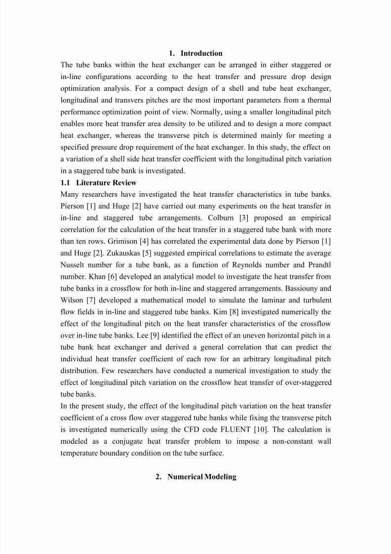
Citation preview
8/13/2019 Heat transfer in staggered tube banks
http://slidepdf.com/reader/full/heat-transfer-in-staggered-tube-banks 1/9
Sensitivity study on the variation of a shell side heat transfer
coefficient with longitudinal pitch variation in a staggered tube bank
ASHRAF ALFANDI
University of Science and Technology, Advanced Nuclear System EngineeringDepartment, 217 Gajeong-Ro Yuseong-Gu, Daejeon, 305-350, Republic of Korea
Young In Kim, Hyungi Yoon, Namgyun Jeong and Juhyeon Yoon
Korea Atomic Energy Research Institute, 989-111 Daedeok-Daero, Yuseong-Gu,
Daejeon, 305-353, Republic of Korea
[email protected], [email protected], [email protected]
The corresponding author: [email protected]
Abstract
In designing compact heat exchangers, the tube bank arrangement is of high
importance since the variation of the longitudinal and transverse pitches affects the
heat transfer and pressure drop in a heat exchanger. Smaller pitches allow a high
performance compact heat exchanger at the expense of a high pressure drop.
Normally, the transverse tube pitch is determined by the given requirement on the
pressure drop limit through the heat exchanger. The longitudinal pitch has a quite
different effect on the heat transfer and pressure drop depending on the in-line and
staggered tube banks, respectively. In this study, the effect on a shell-side heat
transfer coefficient is investigated using the CFD code FLUENT with a variation in
longitudinal pitch to diameter ratio, SL, in the range of 1.15 to 2.6 with a fixed
transverse pitch to diameter ratio. For the benchmark purposes with the available
empirical correlation, typical thermal-hydraulic conditions for the Zukauskas
correlation are assumed. Many sensitivity calculations for different mesh sizes and
turbulent models are performed to check the accuracy of the numerical solution. A
realizable κ -ε turbulence model was found to be in good agreement with results of the
Zukauskas correlation among the other turbulence models, at least for the staggeredtube bank. It was found that the average heat transfer coefficient of a crossflow over a
staggered tube bank calculated using FLUENT is in good agreement with the
Zukauskas correlation-calculated heat transfer coefficient in the range of 1.15 – 2.6.
For a staggered tube bank, using the Zukauskas correlation seems to be valid down to
SL = 1.15.
Keyword: Heat transfer coefficient, staggered tube bank, longitudinal pitch,
crossflow, turbulence model.
8/13/2019 Heat transfer in staggered tube banks
http://slidepdf.com/reader/full/heat-transfer-in-staggered-tube-banks 2/9
1. Introduction
The tube banks within the heat exchanger can be arranged in either staggered or
in-line configurations according to the heat transfer and pressure drop design
optimization analysis. For a compact design of a shell and tube heat exchanger,
longitudinal and transvers pitches are the most important parameters from a thermal
performance optimization point of view. Normally, using a smaller longitudinal pitch
enables more heat transfer area density to be utilized and to design a more compact
heat exchanger, whereas the transverse pitch is determined mainly for meeting a
specified pressure drop requirement of the heat exchanger. In this study, the effect on
a variation of a shell side heat transfer coefficient with the longitudinal pitch variation
in a staggered tube bank is investigated.
1.1 Literature Review
Many researchers have investigated the heat transfer characteristics in tube banks.Pierson [1] and Huge [2] have carried out many experiments on the heat transfer in
in-line and staggered tube arrangements. Colburn [3] proposed an empirical
correlation for the calculation of the heat transfer in a staggered tube bank with more
than ten rows. Grimison [4] has correlated the experimental data done by Pierson [1]
and Huge [2]. Zukauskas [5] suggested empirical correlations to estimate the average
Nusselt number for a tube bank, as a function of Reynolds number and Prandtl
number. Khan [6] developed an analytical model to investigate the heat transfer from
tube banks in a crossflow for both in-line and staggered arrangements. Bassiouny andWilson [7] developed a mathematical model to simulate the laminar and turbulent
flow fields in in-line and staggered tube banks. Kim [8] investigated numerically the
effect of the longitudinal pitch on the heat transfer characteristics of the crossflow
over in-line tube banks. Lee [9] identified the effect of an uneven horizontal pitch in a
tube bank heat exchanger and derived a general correlation that can predict the
individual heat transfer coefficient of each row for an arbitrary longitudinal pitch
distribution. Few researchers have conducted a numerical investigation to study the
effect of longitudinal pitch variation on the crossflow heat transfer of over-staggered
tube banks.
In the present study, the effect of the longitudinal pitch variation on the heat transfer
coefficient of a cross flow over staggered tube banks while fixing the transverse pitch
is investigated numerically using the CFD code FLUENT [10]. The calculation is
modeled as a conjugate heat transfer problem to impose a non-constant wall
temperature boundary condition on the tube surface.
2. Numerical Modeling
8/13/2019 Heat transfer in staggered tube banks
http://slidepdf.com/reader/full/heat-transfer-in-staggered-tube-banks 3/9
8/13/2019 Heat transfer in staggered tube banks
http://slidepdf.com/reader/full/heat-transfer-in-staggered-tube-banks 4/9
In this study, typical thermal hydraulic parameters are taken from typical
once-through steam generator design data [11]. These numerical values just represent
a physically meaningful set of data.
All numerical calculations are performed at a Reynolds number of 8.9×10⁴. Having
known ReD, the maximum velocity can be calculated by
= (3)
In the range of 1.15 – 2.6 of SL, the flow will have a maximum velocity of 1.09 m/s at
the transverse cross section [12] because
√ () ()
(4)
At the inlet boundary, the hot water flow rate is set to 1.59 kg/s and the upstream bulk
temperature is assumed to be constant at 297.4ᵒC. Considering the repeated pattern ofthe flow at the inlet and outlet boundaries, a periodic boundary condition is prescribed.
Because of the symmetry in the upper and lower parts of the computational domain,
symmetric boundary conditions are applied, as shown in figure 2. The working fluid
in the tube side is assumed to have a constant saturation temperature of 255.27ᵒC.
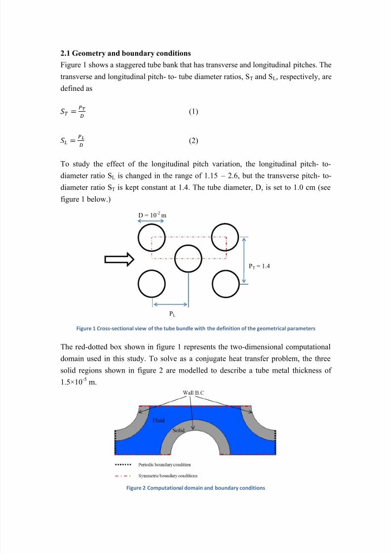
2.2 Mesh generation
Figure 3 Computational grid
An unstructured, the quadrilateral dominant method is used to generate a grid for the
entire computational domain. Two examples of the meshes are shown in figures 3 (a)
and 3 (b) for the two extreme cases at SL = 1.15 and 2.6, having a total number of
elements of 58,040 and 109,615, respectively.
A two-layer model is adapted to treat the wall boundary layer near the wall. Along the
fluid – solid interface boundary, a maximum of 25 inflation layers, are used to have a
maximum y = 2.5×10⁻⁶ m at the first grid so that y+ ~ 0.5.
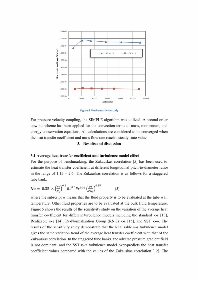
A mesh sensitivity study was conducted by investigating several cases of different
grid numbers, as shown in figure 4. The mesh was continually refined until a variationin the heat transfer coefficient is small enough to be 0.15 %.
8/13/2019 Heat transfer in staggered tube banks
http://slidepdf.com/reader/full/heat-transfer-in-staggered-tube-banks 5/9
8/13/2019 Heat transfer in staggered tube banks
http://slidepdf.com/reader/full/heat-transfer-in-staggered-tube-banks 6/9
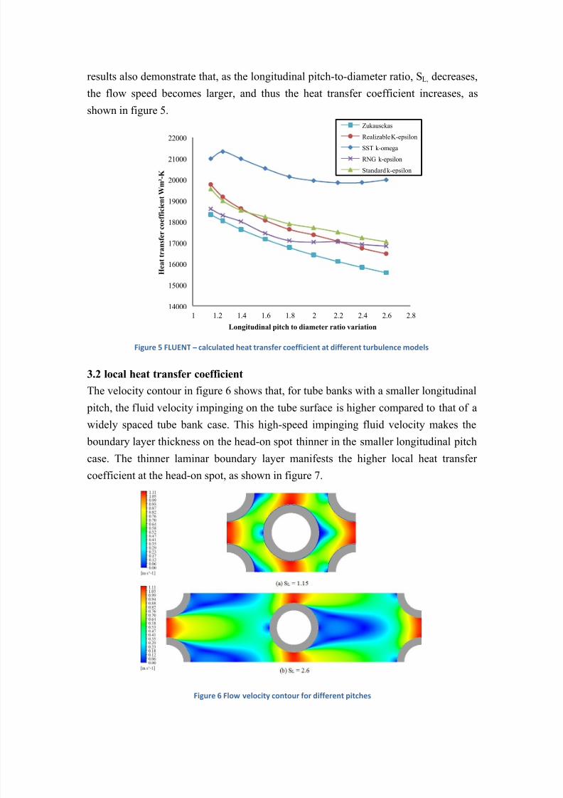
results also demonstrate that, as the longitudinal pitch-to-diameter ratio, SL, decreases,
the flow speed becomes larger, and thus the heat transfer coefficient increases, as
shown in figure 5.
Figure 5 FLUENT – calculated heat transfer coefficient at different turbulence models
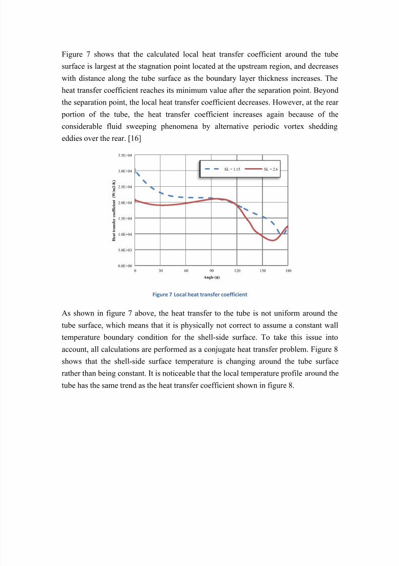
3.2 local heat transfer coefficient
The velocity contour in figure 6 shows that, for tube banks with a smaller longitudinal
pitch, the fluid velocity impinging on the tube surface is higher compared to that of a
widely spaced tube bank case. This high-speed impinging fluid velocity makes the
boundary layer thickness on the head-on spot thinner in the smaller longitudinal pitch
case. The thinner laminar boundary layer manifests the higher local heat transfer
coefficient at the head-on spot, as shown in figure 7.
Figure 6 Flow velocity contour for different pitches
14000
15000
16000
17000
18000
19000
20000
21000
22000
1 1.2 1.4 1.6 1.8 2 2.2 2.4 2.6 2.8
H e a t t r a n s f e r c o e f f i c i e n t W m ² - K
Longitudinal pitch to diameter ratio variation
Zukausckas
Realizable K-epsilonSST k-omega
RNG k-epsilon
Standard k-epsilon
8/13/2019 Heat transfer in staggered tube banks
http://slidepdf.com/reader/full/heat-transfer-in-staggered-tube-banks 7/9
8/13/2019 Heat transfer in staggered tube banks
http://slidepdf.com/reader/full/heat-transfer-in-staggered-tube-banks 8/9
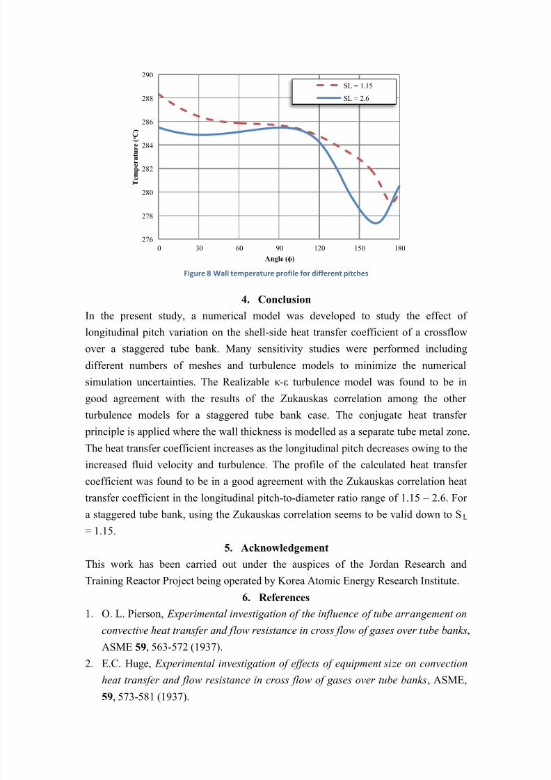
Figure 8 Wall temperature profile for different pitches
4. Conclusion
In the present study, a numerical model was developed to study the effect of
longitudinal pitch variation on the shell-side heat transfer coefficient of a crossflow
over a staggered tube bank. Many sensitivity studies were performed including
different numbers of meshes and turbulence models to minimize the numerical
simulation uncertainties. The Realizable κ -ε turbulence model was found to be in
good agreement with the results of the Zukauskas correlation among the other
turbulence models for a staggered tube bank case. The conjugate heat transfer
principle is applied where the wall thickness is modelled as a separate tube metal zone.
The heat transfer coefficient increases as the longitudinal pitch decreases owing to the
increased fluid velocity and turbulence. The profile of the calculated heat transfer
coefficient was found to be in a good agreement with the Zukauskas correlation heat
transfer coefficient in the longitudinal pitch-to-diameter ratio range of 1.15 – 2.6. For
a staggered tube bank, using the Zukauskas correlation seems to be valid down to SL
= 1.15.
5. Acknowledgement
This work has been carried out under the auspices of the Jordan Research and
Training Reactor Project being operated by Korea Atomic Energy Research Institute.
6. References
1. O. L. Pierson, Experimental investigation of the influence of tube arrangement on
convective heat transfer and flow resistance in cross flow of gases over tube banks,
ASME 59, 563-572 (1937).
2. E.C. Huge, Experimental investigation of effects of equipment size on convection
heat transfer and flow resistance in cross flow of gases over tube banks, ASME,59, 573-581 (1937).
276
278
280
282
284
286
288
290
0 30 60 90 120 150 180
T e m p e r a t u r e ( ᵒ C
)
Angle (ϕ)
SL = 1.15
SL = 2.6
8/13/2019 Heat transfer in staggered tube banks
http://slidepdf.com/reader/full/heat-transfer-in-staggered-tube-banks 9/9
3. A.P. Colburn, A method of correlating forced convection heat transfer data and a
comparison with fluid friction, Trans. Am. Inst. Chem. Eng. 29, 174-210 (1933).
4. E.D. Grimison, Correlation and utilization of new data on flow resistance and
heat transferfor cross flow of gases over tube banks, ASME 59, 583-594 (1933).
5. A.A. Zukauskas, Heat Transfer from Tubes in Crossflow, Adv. Heat Transfer 8,
93-160 (1972).
6. W.A. Khan, J.R. Culham, M.M. Yovanovich, Convection heat transfer from tube
banks in cross flow: Analytical approach, Int. J. Heat Mass Transfer 49,
4831-4838 (2006).
7. M. Khalil Bassiouny, A. Safwat Wilson, Modeling of heat transfer for flow across
tube banks, Chem. Eng. Process 39, 1-14 (2000).
8. T. Kim, Effect of longitudinal pitch on convective heat transfer in crossflow over
in-line tube banks, Ann. Nucl. Energy 57, 209-215 (2013).9. D. Lee, A. Joon, S. Shin, Uneven longitudinal pitch effect on tube bank heat
transfer in cross flow, Appl. Them. Eng 51, 937-947 (2013).
10. Inc. Fluent, Fluent User’s Guide (2006).
11. J. Yoon, J.-P. Kim, H.-Y. Kim, D. J. Lee, M. H. Chang, Development of a
computer code, ONCESG, for thermal-hydraulic design of a once-through steam
generator, J. Nucl. Sci. Technol 37, 445-454 (2000)
12. F. Kreth, M.S. Bohn, Principles of heat transfer (Books/Cole, Thomas Learning,
2001).13. B.E. Launder, D.B. Spalding, Lectures in mathematical models of turbulence.
(Academic Press, 1982).
14. T.-H. Shih, W.W. liou, A. Shibber, Z. Yang, J. Zhu, A new κ -ε eddy-viscosity model
for high reynolds number turbulent flows-Model development and validation,
Computer Fluids 24, 227-238 (1995).
15. V. Yakhot, S.A. Orszag, S. Thangma, T.B. Gatski, S.G. Speziale, Development of
turbulent models for shear flows by a double expansion technique, phys. Fluids A
4, 1510-1520 (1992).
16. J.E. Bardina, P.G. Huang, T.J. Coakley, Turbulence modelling validation, testing,
and development. NASA TM 110446, (1997).


![Abstract - International Gas Unionmembers.igu.org/old/IGU Events/igrc/igrc-2014... · Robinson and Briggs [5] pressure drop correlation for a staggered tube layout 2: SYSTEM DESCRIPTION](https://img.pdfslide.net/doc/110x75/5e74803dece8ee3f282f1568/abstract-international-gas-eventsigrcigrc-2014-robinson-and-briggs-5.jpg)