Embed Size (px)
Citation preview
Helicity Signal Generation at Jefferson LabR. Suleiman, R. Flood, J. Hansknecht, S. Higgins, M. Poelker
Thomas Jefferson National Accelerator Facility, Newport News, VA 23606, U.S.A.
Sunday, May 07, 2023
Abstract
Helicity board was designed to gene ….
Introduction
A new Helicity Control Board was installed in November 2009. The new board provides more outputs and easier to re-program than the old one. The initial programming was chosen to meet the requirements of the current experiments. Changes are very easy to make and there is no limitation on the outputs. However, there are two main issues to keep in mind when selecting the outputs: first, the Pockels Cell response to the high voltage (HV) switching and, second, the Data Acquisition systems (DAQ) of the Halls. In specific, the choice of the T_Settle has to be long enough to allow for the Pockels Cell to “settle” and the choice of the helicity reversal frequency has to be matched with the speed of the DAQ.
The Helicity Board is an “Advanced Programmable Logic Generator”. One of its outputs (Helicity Flip signal) is used to control the high voltage (+3 kV or -3 kV) of the Pockels Cell on the Laser Table in CEBAF Injector. This change in Pockels Cell HV changes the circular polarization (left-handed or right-handed) of the laser light which in turn changes the direction of spin of the photo-emitted electrons relative to its momentum. The electron spin is either aligned parallel or anti parallel to the electron momentum; this is called electron helicity. Thus one signal from this logic generator changes the helicity of the electron beam and hence this board is called the Helicity Board.
The Helicity Board will operate at one of four timing selections. Three are fixed-frequencies of 30 Hz, 120 Hz, and 240 Hz triggered by "Line Sync". The phase locking is forced during the last T_Stable period. The T_Settle time period may be chosen from the T_Settle Register values. The T_Stable selection is disabled in this mode.
The fourth mode of operation allows the board to operate in free-running mode, where T_Settle and T_Stable values are selected from the values in the registers.
The Reporting Delay is selected from a register and determines how many windows there are between the real time Helicity Flip signal and the Delayed Helicity signal.
The Helicity Pattern may be selected to provide three pseudo-random patterns: Pair, Quartet, and Octet. In these patterns, the first window is chosen using the pseudo-random bit Shift Register. The forth pattern is pair Toggle. The free-running mode has two additional pseudo-random patterns to choose from: Hexo-Quad and Octo-Quad.
Note that when talking about frequency: it is the frequency of the T_Settle signal ( f ) and this will be labeled as the Helicity Board Frequency. Note that the Pair Sync signal will have f /2 frequency. The Pattern Sync signal will havef /4when the helicity pattern is Quartet. The Delayed Helicity will have a frequency of f /2 when in Toggle Pattern. When the pattern is one of the pseudo-random patterns, the frequency of the Delayed Helicity signal varies.
In this document, there are three ways to indicate a helicity state: either 0, 1 (+,−¿or . Each helicity state is called a window.
Why a New Helicity Board?
It was time to upgrade the Helicity Board for the following reasons:
I. Clean up leftovers from G0. Drop the “MPS” label.
II. Make it easy to program and easy to choose any reversal rate and any T_Settle time.
III. Change the Shift Register to 30-Bit. The old one is 24-Bit and would repeat in a shorter time (1 day compared to 50 days in the case when the Helicity Board frequency is 1 kHz).
IV. Add a new pattern: Octet (±∓∓±¿ or∓±±∓¿).
V. Add new fiber output signals:
1. 2 additional outputs for 4-way Intensity Attenuator (IA) feedback scheme where the applied IA voltage is determined not only from the current helicity state but also from the current and previous helicity patterns.
2. Output of the Helicity Board 20 MHz Clock signal.
Helicity Board Modes
There are two modes of the Helicity Board:
2
Line Sync Mode
There are three line synced fixed-frequencies of 30 Hz, 120 Hz, and 240 Hz triggered by "Line Sync". The phase locking is forced during the last T_Stable period. The T_Settle time period may be chosen from the T_Settle Register. You cannot choose T_Stable in this mode only T_Settle. Once you select Line Sync Mode, the T_Stable menu bar is disabled.
Free Clock Mode
This mode of operation allows the board to operate in free-running mode, where the T_Settle and T_Stable values are selected from the tables below. In this mode, you can select any T_Settle and any T_Stable. This is the DEFAULT Mode.
Helicity Board Registers
These registers have the listed values. We can choose whatever we want to fill them.
T_Settle Register
There is a Five-bit R/W register that determines the "T_Settle" portion of the helicity period. The settle time selections are as follows:
10 µs, 20 µs, 30 µs, 40 µs, 50 µs, 60 µs, 70 µs, 80 µs, 90 µs, 100 µs, 110 µs, 120 µs, 130 µs, 140 µs, 150 µs, 160 µs, 170 µs, 180 µs, 190 µs, 200 µs, 250 µs, 300 µs, 350 µs, 400 µs, 450 µs, 500 µs, 550 µs, 600 µs, 700 µs, 800 µs, 900 µs, 1000 µs.
T_Stable Register
There is a Five-bit R/W register that determines the "T_Stable" portion of the helicity period. The stable time selections are as follows:
400 µs, 500 µs, 600 µs, 700 µs, 800 µs, 900 µs, 971.65 μs, 1000 µs, 1001.65 μs, 1318.90 μs, 1348.90 μs, 1500 µs, 2000 µs, 2500 µs, 3000 µs, 3500 µs, 4066.65 µs, 4500 µs, 5000 µs, 5500 µs, 6000 µs, 6500 µs, 7000 µs, 8233.35 µs, 8333.35 µs, 16567 µs, 16667 µs, 33230 µs, 33330 µs, 50000 µs, 100000 µs, 1000000 µs.
3
Helicity Pattern Register
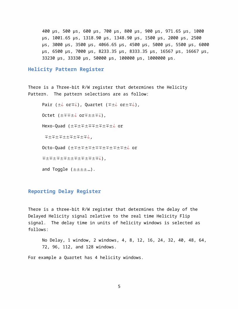
There is a Three-bit R/W register that determines the Helicity Pattern. The pattern selections are as follow:
Pair (±¿ or∓¿), Quartet (∓±¿ or±∓¿),
Octet (±∓∓±¿ or∓±±∓¿),
Hexo-Quad (±∓±∓±∓∓±∓±∓±¿ or
∓±∓±∓±±∓±∓±∓¿ ,
Octo-Quad (±∓±∓±∓±∓∓±∓±∓±∓±¿ or
∓±∓±∓±∓±±∓±∓±∓±∓¿),
and Toggle (±±±±…).
Reporting Delay Register
There is a three-bit R/W register that determines the delay of the Delayed Helicity signal relative to the real time Helicity Flip signal. The delay time in units of helicity windows is selected as follows:
No Delay, 1 window, 2 windows, 4, 8, 12, 16, 24, 32, 40, 48, 64, 72, 96, 112, and 128 windows.
For example a Quartet has 4 helicity windows.
Software
EPICS Channels
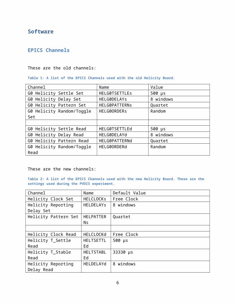
These are the old channels:
Table 1: A list of the EPICS Channels used with the old Helicity Board.
Channel Name ValueG0 Helicity Settle Set HELG0TSETTLEs 500 µsG0 Helicity Delay Set HELG0DELAYs 8 windows
4
G0 Helicity Pattern Set HELG0PATTERNs QuartetG0 Helicity Random/Toggle Set HELG0ORDERs Random
G0 Helicity Settle Read HELG0TSETTLEd 500 µsG0 Helicity Delay Read HELG0DELAYd 8 windowsG0 Helicity Pattern Read HELG0PATTERNd QuartetG0 Helicity Random/Toggle Read HELG0ORDERd Random
These are the new channels:
Table 2: A list of the EPICS Channels used with the new Helicity Board. These are the settings used during the PVDIS experiment.
Channel Name Default ValueHelicity Clock Set HELCLOCKs Free ClockHelicity Reporting Delay Set HELDELAYs 8 windowsHelicity Pattern Set HELPATTERNs Quartet
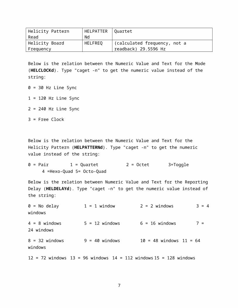
Helicity Clock Read HELCLOCKd Free ClockHelicity T_Settle Read HELTSETTLEd 500 µsHelicity T_Stable Read HELTSTABLEd 33330 µsHelicity Reporting Delay Read HELDELAYd 8 windowsHelicity Pattern Read HELPATTERNd QuartetHelicity Board Frequency HELFREQ (calculated frequency, not a readback) 29.5596 Hz
Below is the relation between the Numeric Value and Text for the Mode (HELCLOCKd). Type "caget -n" to get the numeric value instead of the string:
0 = 30 Hz Line Sync
1 = 120 Hz Line Sync
2 = 240 Hz Line Sync
3 = Free Clock
Below is the relation between the Numeric Value and Text for the Helicity Pattern (HELPATTERNd). Type "caget -n" to get the numeric value instead of the string:
0 = Pair 1 = Quartet 2 = Octet 3=Toggle 4 =Hexo-Quad 5= Octo-Quad
Below is the relation between Numeric Value and Text for the Reporting Delay (HELDELAYd). Type "caget -n" to get the numeric value instead of the string:
5
0 = No delay 1 = 1 window 2 = 2 windows 3 = 4 windows
4 = 8 windows 5 = 12 windows 6 = 16 windows 7 = 24 windows
8 = 32 windows 9 = 40 windows 10 = 48 windows 11 = 64 windows
12 = 72 windows 13 = 96 windows 14 = 112 windows 15 = 128 windows
Figure 1: Helicity Board Control Screen. There are two pull-down menus for T_Settle and two menus for T_Stable. In Free Clock Mode, all menus are available. In Line Sync Mode, only the menus of T_Settle are active; T_Stable menus are inactive.
Programming
Figure 1 shows the control screen for the new Helicity Board. The following shows how to use the board.
1. Select Mode:
I. Line Sync (force phase-locking during last T_Stable):
o Select Helicity Board Frequency f : 30 , 120, or 240 Hz Line Sync
o Select T_Settle value between 10 µs – 1,000 µs
6
o Display T_Stable (T_Stable selection is disabled):
T ¿Stable=1f−T ¿ Settle
The Line Sync jitter will show up in the last window of the pattern. For example with “240 Hz Line Sync” and Octet Pattern, the first 7 windows will have a length of 4,167 µs and the 8 th window will be 4167 µs ± Line Sync jitter. The length of this last window can be used to monitor the jitter in the 60 Hz line frequency.
II. Free Clock:
o Select T_Settle value between 10 µs – 1,000 µs
o Select T_Stable value between 400 µs – 1,000,000 µs
o Display Helicity Board Frequency (Reversal Rate):
f= 1T¿ Settle+T¿ Stable
2. Select Helicity Pattern:
Pair, Quartet, Octet, or Toggle. The free-running mode has two additional patterns to choose from: Hexo-Quad and Octo-Quad. If these two additional patterns were inadvertently selected with the Line Sync mode, the board will default to Toggle.
3. Select Reporting Delay: n Windows, n = 0 … 128 windows
Pseudo-random Helicity Generator
A 30-Bit Shift Register is used to generate the pseudo-random bits: 0, 1 (or+,−¿) which determines the first window of a pattern. This removes any correlation between the helicity of the beam and any other device in the accelerator or in the Hall. It is a pseudo-random bit, not “random”, because it is deterministic, once a sequence of 30 bits is known, the next bits can be predicted, and it repeats after the maximal length. For any initial register value, there are 2 30 – 1 = 1,073,741,823 (maximal length) random bits before the sequence repeats, 50 days for 1000 Hz helicity reversal rate and a Quartet Pattern. Figure 2 shows the 30-Bit shift register.
7
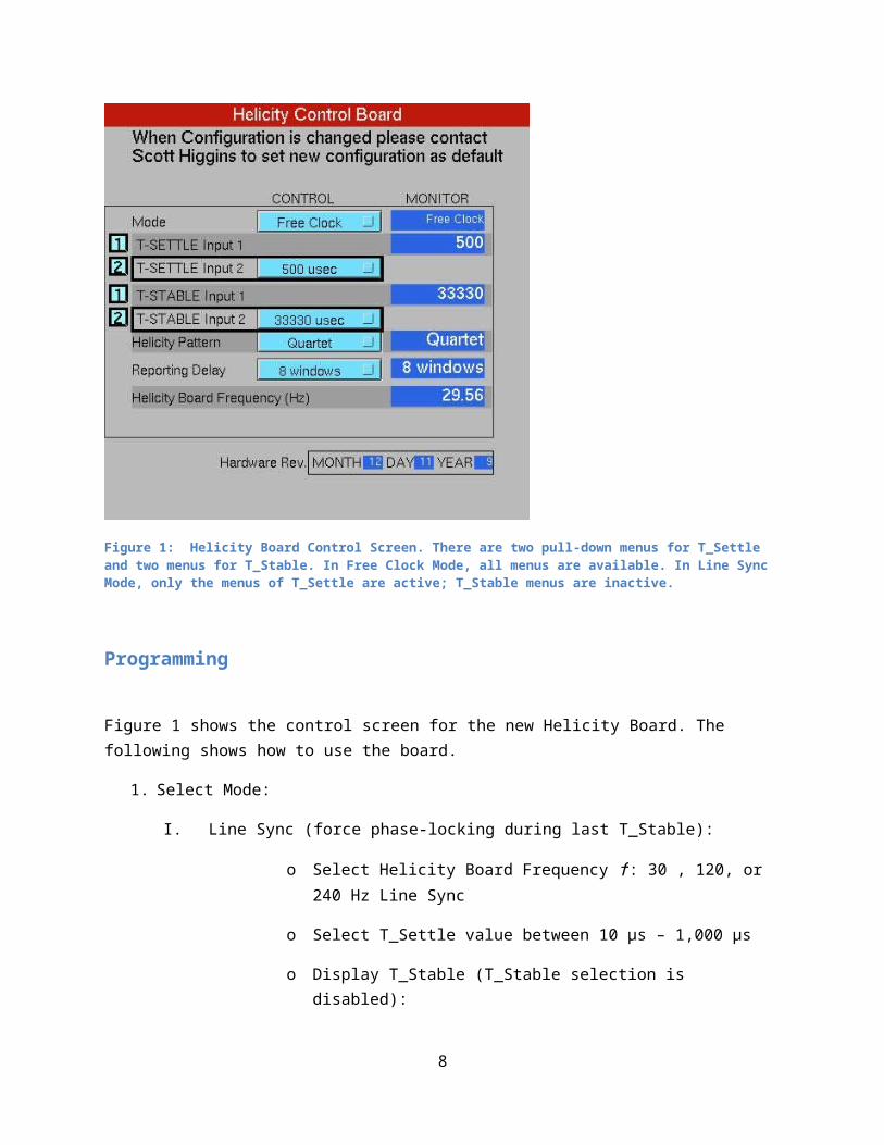
Figure 2: The 30 Bit Shift Register used to generate the pseudo-random bit. This bit is an XOR of bits 30, 29, 28, and 7.
The following C++ code can be used to initially fill the Shift Register and to predict the helicity bit:
UInt_t RanBit(UInt_t hRead){
UInt_t bit7 = (fgShreg & 0x00000040) != 0; UInt_t bit28 = (fgShreg & 0x08000000) != 0; UInt_t bit29 = (fgShreg & 0x10000000) != 0; UInt_t bit30 = (fgShreg & 0x20000000) != 0; UInt_t newbit = (bit30 ^ bit29 ^ bit28 ^ bit7) & 0x1; fgShreg = ( (hRead == 2 ? newbit : hRead) | (fgShreg << 1 )) & 0x3FFFFFFF; return newbit;
}
During analysis of the parity data, the first 30 patterns of each typically 1 hour long data runs are used to initialize the Shift Register (these data patterns are thrown away). After the initialization, the analysis code can predict what the next pseudo-random bit will be. This prediction is compared to the actual helicity of the first window of each pattern in the data to make sure things are fine. Polarimeters and non-parity experiments usually do not perform this check.
Hardware Description
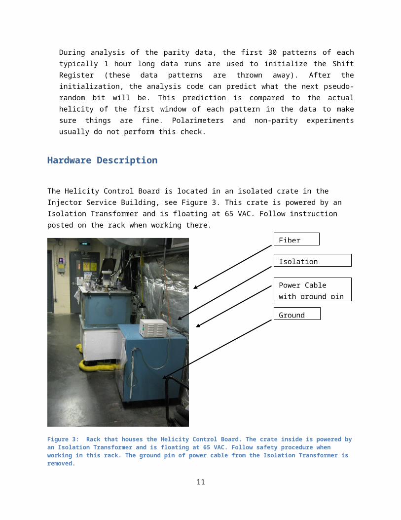
The Helicity Control Board is located in an isolated crate in the Injector Service Building, see Figure 3. This crate is powered by an Isolation Transformer and is floating at 65 VAC. Follow instruction posted on the rack when working there.
8
Figure 3: Rack that houses the Helicity Control Board. The crate inside is powered by an Isolation Transformer and is floating at 65 VAC. Follow safety procedure when working in this rack. The ground pin of power cable from the Isolation Transformer is removed.
9
Ground Rod
Isolation Transformer
Fiber Cable
Power Cable with ground pin removed
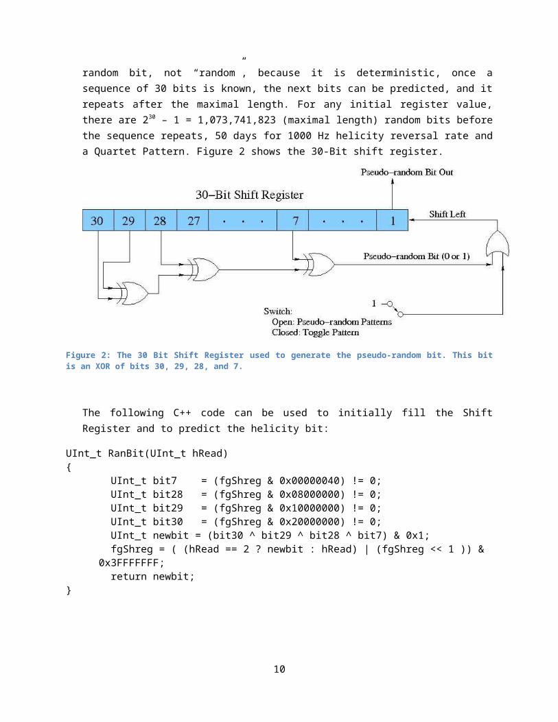
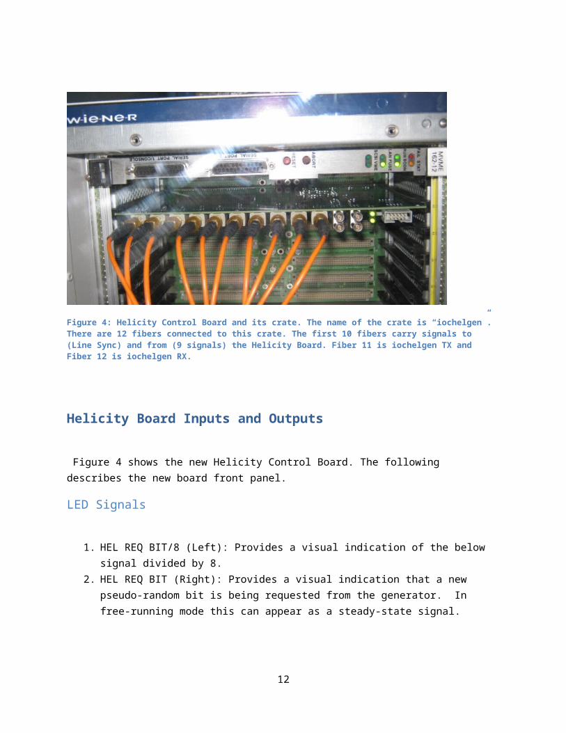
Figure 4: Helicity Control Board and its crate. The name of the crate is “iochelgen”. There are 12 fibers connected to this crate. The first 10 fibers carry signals to (Line Sync) and from (9 signals) the Helicity Board. Fiber 11 is iochelgen TX and Fiber 12 is iochelgen RX.
Helicity Board Inputs and Outputs
Figure 4 shows the new Helicity Control Board. The following describes the new board front panel.
LED Signals
1. HEL REQ BIT/8 (Left): Provides a visual indication of the below signal divided by 8.2. HEL REQ BIT (Right): Provides a visual indication that a new pseudo-random bit is being
requested from the generator. In free-running mode this can appear as a steady-state signal.
LEMO Signals
Upper left to lower right:
1. (Input): Hard-wired Schmitt-trigger TTL input. No connection to the FPGA logic at this time.2. (I/O): Jumper-selectable Schmitt-trigger TTL I/O connection to the FPGA logic. Presently
configured as an output with signal IA1.
10
3. (I/O): Jumper-selectable Schmitt-trigger TTL I/O connection to the FPGA logic. Presently configured as an output with signal Pattern Sync.
4. (I/O): Jumper-selectable Schmitt-trigger TTL I/O connection to the FPGA logic. Presently configured as an output with signal IA0.
Fiber-Optic Inputs ( =820 nm)λ
1. Line Sync: This is the standard accelerator 60 Hz Line Sync signal. It is generated from the zero-crossings of Virginia Power line signal inside the 60 Hz Line Synchronization chassis in rack IN03B21.How accurate is the line frequency? Is it 60 Hz or 60.000 Hz? The answer depends on what time span you average. The 60 Hz power line frequency is known to be relatively stable to about 59.70±0.05 Hz, see Reference [?]. This gives an average period of 16,675±15 µs. This is not exactly Gaussian, there are also outliers.
Fiber-Optic Outputs ( =820 nm)λThe first 8 fibers have Agilent HFBR-1412 transmitters, the Clock fiber has Agilent HFBR-1414 transmitter.
1. Patter Sync (old name QRT): Indicates the start of each pattern. If the pattern is Pair, then it is identical to Pair Sync, see Error: Reference source not found. This signal goes to the users.
2. T_Settle (old name MPS): Indicates the time the DAQs will not collect data allowing for the Pockels Cell to settle. This signal goes to the users and the Helicity Magnets crate. This signal can also be called T_Stable since when it is not true the Pockels Cell is stable.
3. Helicity Flip: This is the signal that goes to the Pockels Cell and IAs. The Pockels Cell changes its voltage with this signal thus changes the circular polarization of the laser light, see Figure 16. Its length is T_Settle + T_Stable. This is the real time helicity and goes only to the Laser Hut in CEBAF Injector. The IAs used to implement helicity-correlated charge feedback receives this signal, too. For one helicity, 0 voltage is applied to the IA and for the other helicity a voltage of up to ±60 V is applied.
4. nHelicity Flip: Complementary to the Helicity Flip signal. This way the board always draws the same current regardless of the helicity being 0 or 1 and further protects against any electrical pickup from the Helicity Board. This real time helicity signal goes to the crate that controls the Helicity Magnets. This is a floating crate located in the 5 MeV region in CEBAF Injector and powered by an isolation transformer with its power cable ground pin removed.
5. Delayed Helicity: This signal is delayed by n windows, where n is chosen from Reporting Delay Register. It tells what the helicity was n windows before. This way no devices on the beamline or
11
in the Halls know what the real time helicity is. In analysis, the data are shifted to match it with its helicity. This signal goes to the users, iocse9 and iocse14 in BSY.
Note that the last n windows of data in each DAQ run are thrown away because the DAQ does not receive the actual helicity of these data (although it is known from helicity prediction).
6. Pair Sync: This signal toggle between 0 and 1, otherwise it looks like the helicity signal. Some DAQs used this signal to construct T_Stable (the integration window). It goes to the users.
7. IA0: This is an IA Control signal that indicates the current pattern. It goes to the Laser Hut in CEBAF Injector.
8. IA1: This is an IA Control signal that indicates the previous pattern. It goes to the Laser Hut in CEBAF Injector.
9. 20 MHz Clock: This is the internal Helicity Control Board clock. It goes to the Qweak ADCs in Injector and Hall C as external clock. It will be used as the reference clock for the ADCs. It will ensure that all the crates are sampling the same times. It is also used to sync the Hall A raster.
The Halls only receive the following signals: T_Settle, Pair Sync, Pattern Sync, and Delayed Helicity. Hall A and Hall C also receive the 20 MHz Clock signal. Only the Parity DAQs make use of the four signals and data are analyzed according to the pattern generated by the Helicity Board. Other DAQs use some of them. For example:
I. Accelerator FFB Measurement of Charge Asymmetry and Position Differences: This measurement uses the BPMs in Hall A Arc (iocse9) and the BPMs in Hall C Arc (iocse14). The only signal these iocs receive is the Delayed Helicity. The analysis software is hard-coded to drop the first part of each helicity window that corresponds to T_Settle (assumes T_Settle is 500 µs). Also a Reporting Delay of 8 windows is hard-coded. The data are analyzed in pairs.
II. 100 keV/500 keV and 5 MeV Injector Mott Polarimeter DAQ: Uses only T_Settle and Delayed Helicity with Reporting Delay set to No Delay and the data are analyzed in pairs regardless of the Helicity Pattern.
III. Hall A Spectrometer DAQ, Parity DAQ, Moller Polarimeter DAQ, and Compton Polarimeter DAQ: All use the four signals and analyze the data according to the pattern generated by the Helicity Board.
IV. Hall B CLAS DAQ and Moller Polarimeter DAQ: Only used Delayed Helicity and Pair Sync. The Pair Sync signal was used to make a 500 µs veto signal for the DAQ. Now, the DAQ has been changed to use T_Settle instead. Data are analyzed in pairs.
V. Hall C QWeak Parity DAQ and Moller Polarimeter DAQ: Hall C does not receive Pair Sync signal. Data are analyzed according to the pattern generated by the Helicity board.
Error: Reference source not found - Figure 13 show the outputs of the helicity board using a scope.
12
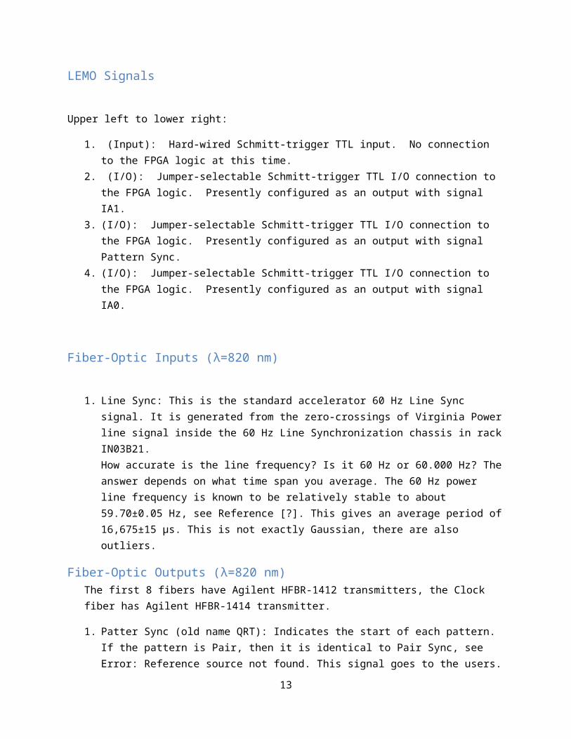
Figure 5: CH1: T_Settle, CH2: Helicity Flip, CH3: nHelicity Flip, CH4: Delayed Helicity. The Helicity Board settings are: No Delay.
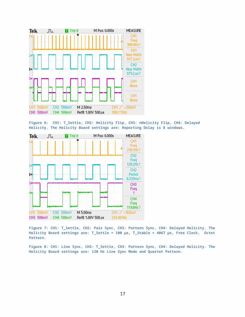
Figure 6: CH1: T_Settle, CH2: Helicity Flip, CH3: nHelicity Flip, CH4: Delayed Helicity. The Helicity Board settings are: Reporting Delay is 8 windows.
13
Figure 7: CH1: T_Settle, CH2: Pair Sync, CH3: Pattern Sync, CH4: Delayed Helicity. The Helicity Board settings are: T_Settle = 100 µs, T_Stable = 4067 µs, Free Clock, Octet Pattern.
Figure 8: CH1: Line Sync, CH2: T_Settle, CH3: Pattern Sync, CH4: Delayed Helicity. The Helicity Board settings are: 120 Hz Line Sync Mode and Quartet Pattern.
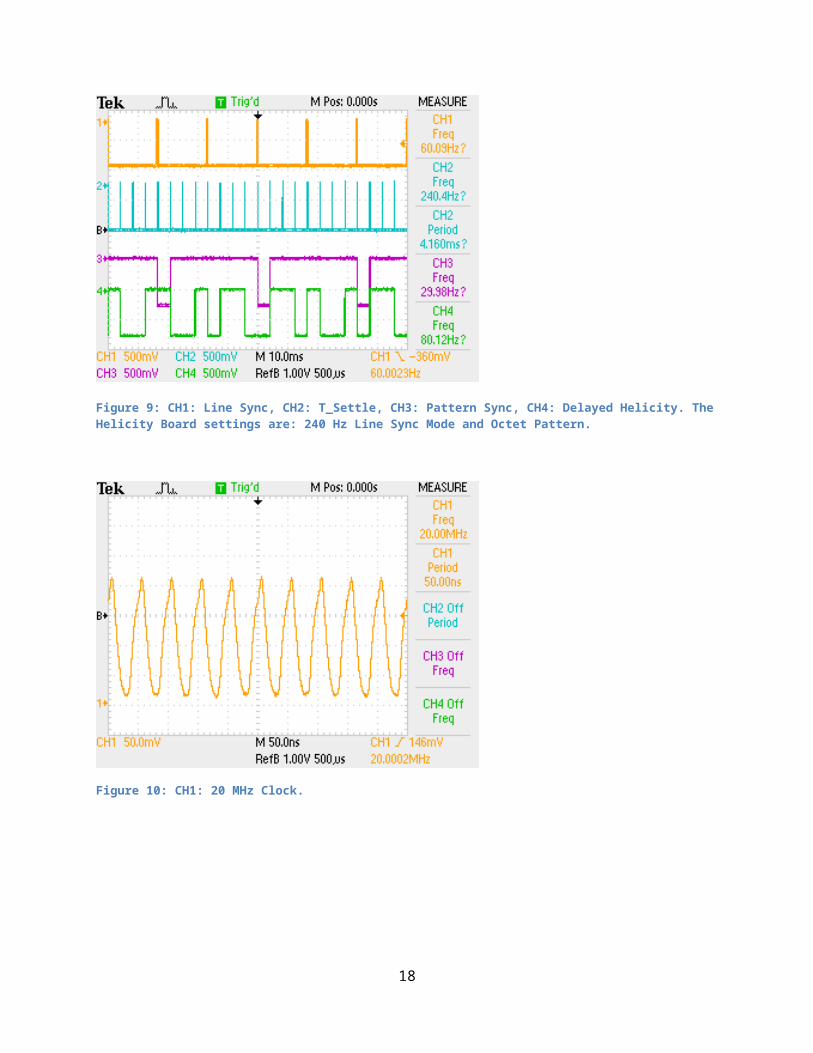
Figure 9: CH1: Line Sync, CH2: T_Settle, CH3: Pattern Sync, CH4: Delayed Helicity. The Helicity Board settings are: 240 Hz Line Sync Mode and Octet Pattern.
14
Figure 10: CH1: 20 MHz Clock.
Figure 11: CH1: Pattern Sync, CH2: Helicity Flip, CH3: IA0, CH4: IA1. The Helicity Board settings are: Pair Pattern.
15
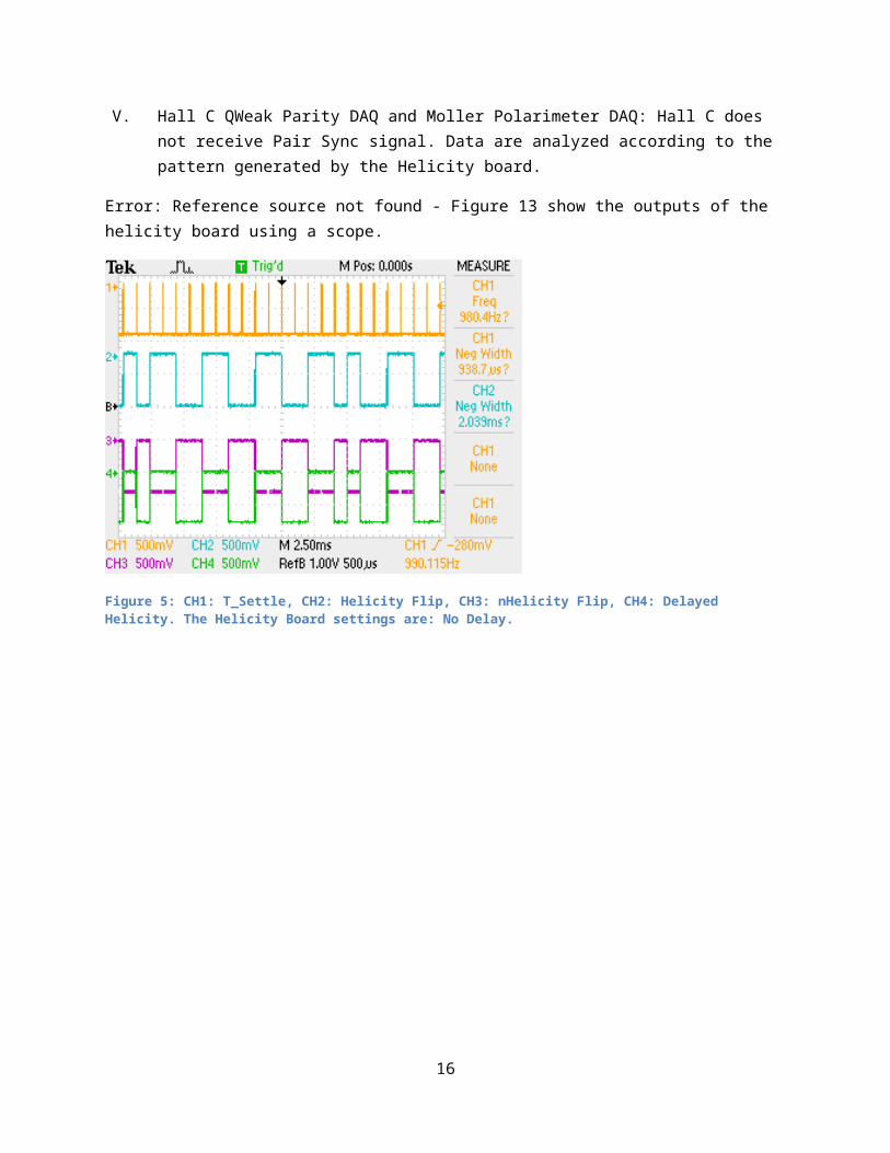
Figure 12: CH1: Pattern Sync, CH2: Helicity Flip, CH3: IA0, CH4: IA1. The Helicity Board settings are: Quartet Pattern.
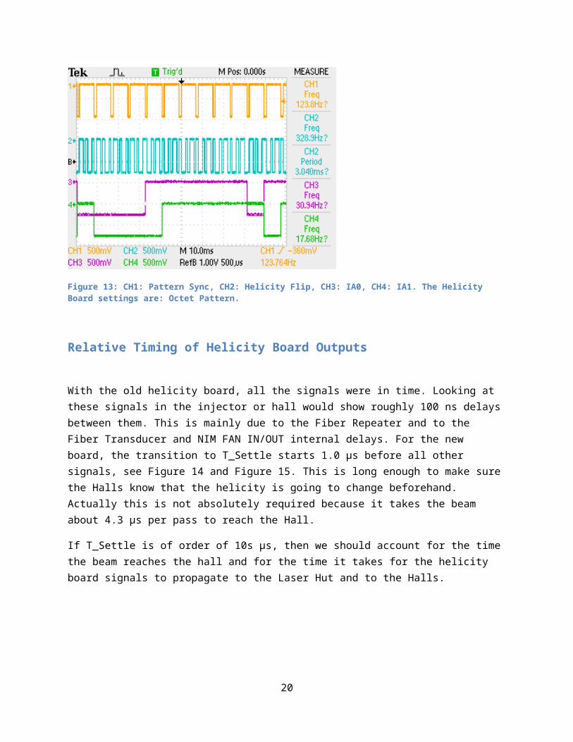
Figure 13: CH1: Pattern Sync, CH2: Helicity Flip, CH3: IA0, CH4: IA1. The Helicity Board settings are: Octet Pattern.
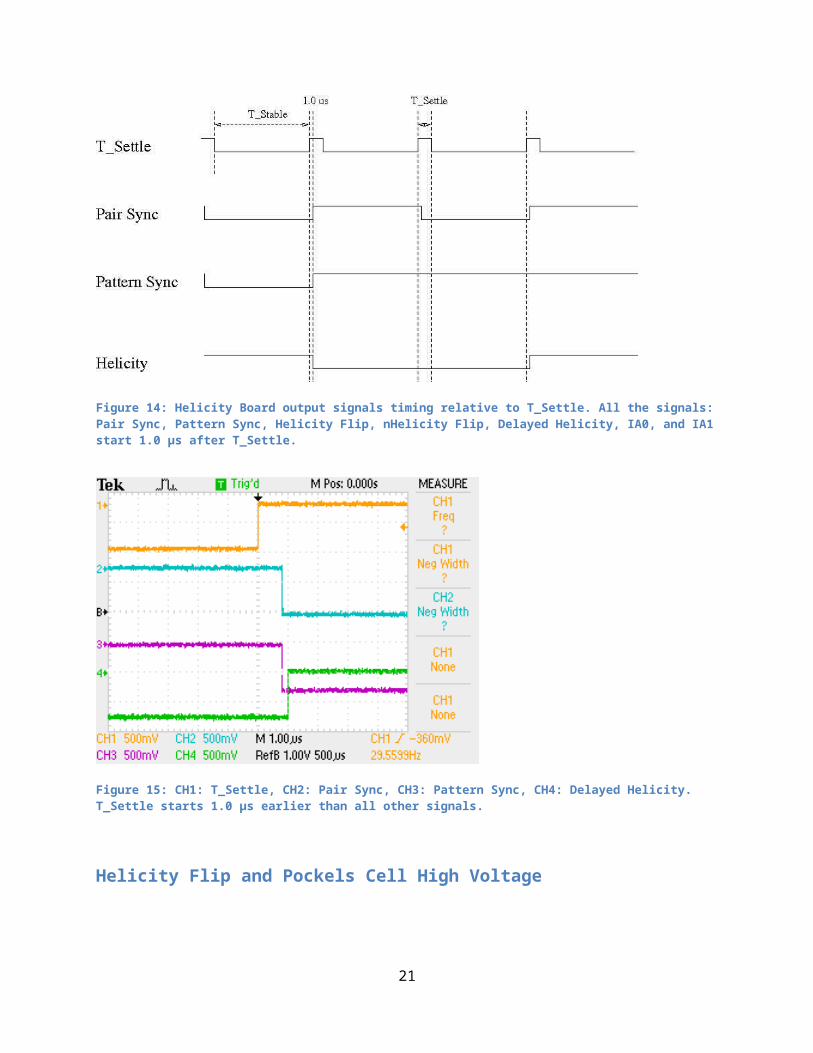
Relative Timing of Helicity Board Outputs
With the old helicity board, all the signals were in time. Looking at these signals in the injector or hall would show roughly 100 ns delays between them. This is mainly due to the Fiber Repeater and to the Fiber Transducer and NIM FAN IN/OUT internal delays. For the new board, the transition to T_Settle
16
starts 1.0 µs before all other signals, see Figure 14 and Figure 15. This is long enough to make sure the Halls know that the helicity is going to change beforehand. Actually this is not absolutely required because it takes the beam about 4.3 µs per pass to reach the Hall.
If T_Settle is of order of 10s µs, then we should account for the time the beam reaches the hall and for the time it takes for the helicity board signals to propagate to the Laser Hut and to the Halls.
Figure 14: Helicity Board output signals timing relative to T_Settle. All the signals: Pair Sync, Pattern Sync, Helicity Flip, nHelicity Flip, Delayed Helicity, IA0, and IA1 start 1.0 µs after T_Settle.
Figure 15: CH1: T_Settle, CH2: Pair Sync, CH3: Pattern Sync, CH4: Delayed Helicity. T_Settle starts 1.0 µs earlier than all other signals.
17
Helicity Flip and Pockels Cell High Voltage
Figure 16 shows the Pockels Cell (PC) high voltage (HV) while the helicity is flipping. The Pockels Cell HV changes between +3 kV to -3 kV.
Figure 16: Pockels Cell HV showing the Helicity Flip.
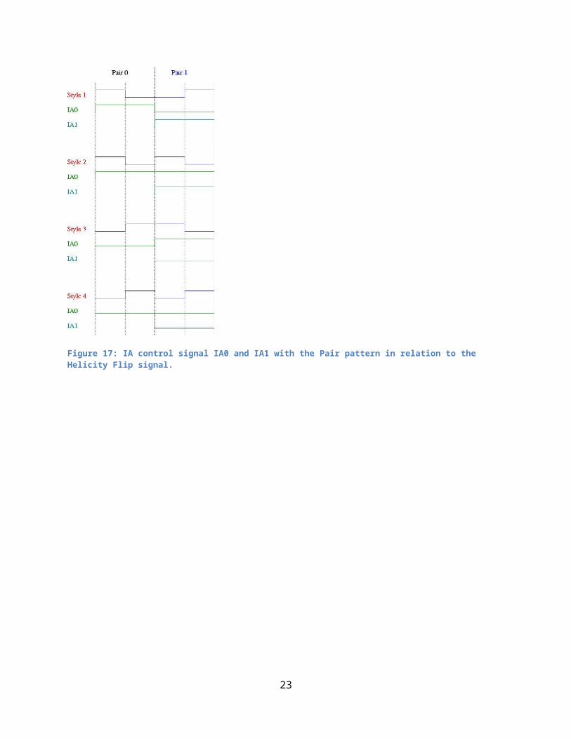
IA Control Signals
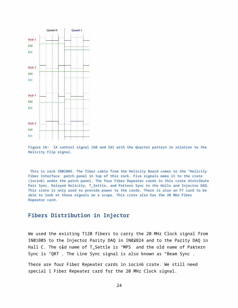
To be able to do charge feedback with Intensity Attenuator (IA) and cancel the electro-optical hysteresis of the Pockels Cell, the Helicity Board has two output signals identifying the current and the previous patterns. Figure 17 shows the IA0 and IA1 signals when the Pair pattern is selected. Figure 18 shows the same when the Quartet pattern is selected. Similarly for the Octet pattern.
18
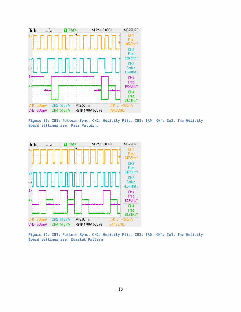
Figure 17: IA control signal IA0 and IA1 with the Pair pattern in relation to the Helicity Flip signal.
Figure 18: IA control signal IA0 and IA1 with the Quartet pattern in relation to the Helicity Flip signal.
19
This is rack IN01B05. The fiber cable from the Helicity Board comes to the “Helicity Fiber Interface” patch panel in top of this rack. Five signals make it to the crate (iocin6) under the patch panel. The four Fiber Repeater cards in this crate distribute Pair Sync, Delayed Helicity, T_Settle, and Pattern Sync to the Halls and Injector DAQ. This crate is only used to provide power to the cards. There is also an FT card to be able to look at these signals on a scope. This crate also has the 20 MHz Fiber Repeater card.
Fibers Distribution in Injector
We used the existing T120 fibers to carry the 20 MHz Clock signal from IN01B05 to the Injector Parity DAQ in IN02B24 and to the Parity DAQ in Hall C. The old name of T_Settle is “MPS” and the old name of Pattern Sync is “QRT”. The Line Sync signal is also known as “Beam Sync”.
There are four Fiber Repeater cards in iocin6 crate. We still need special 1 Fiber Repeater card for the 20 MHz Clock signal.
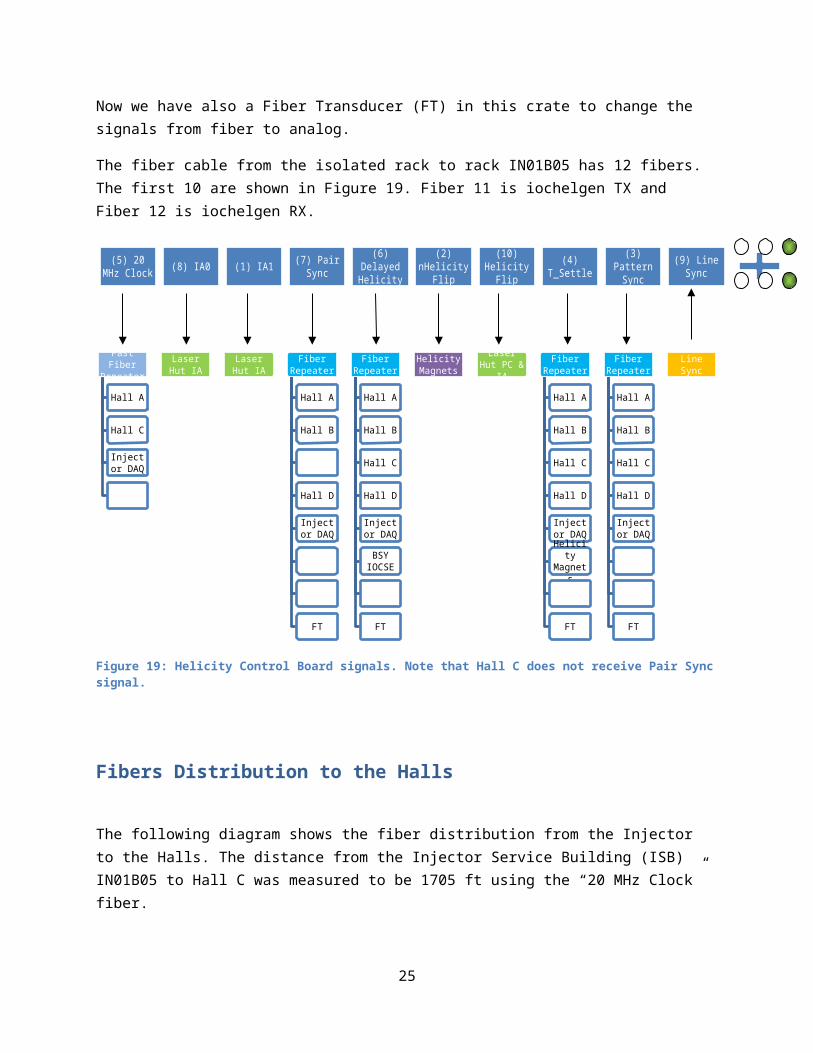
Now we have also a Fiber Transducer (FT) in this crate to change the signals from fiber to analog.
The fiber cable from the isolated rack to rack IN01B05 has 12 fibers. The first 10 are shown in Figure 19. Fiber 11 is iochelgen TX and Fiber 12 is iochelgen RX.
Figure 19: Helicity Control Board signals. Note that Hall C does not receive Pair Sync signal.
20
(5) 20 MHz Clock (8) IA0 (1) IA1 (7) Pair Sync (6) Delayed
Helicity(2) nHelicity
Flip(10) Helicity
Flip (4) T_Settle (3) Pattern Sync (9) Line Sync
Fast Fiber Repeater
Hall A
Hall C
Injector DAQ
Laser Hut IA Laser Hut IA Fiber Repeater
Hall A
Hall B
Hall D
Injector DAQ
FT
Fiber Repeater
Hall A
Hall B
Hall C
Hall D
Injector DAQ
BSY IOCSE
FT
Helicity Magnets
Laser Hut PC & IA
Fiber Repeater
Hall A
Hall B
Hall C
Hall D
Injector DAQ
Helicity Magnets
FT
Fiber Repeater
Hall A
Hall B
Hall C
Hall D
Injector DAQ
FT
Line Sync
Fibers Distribution to the Halls
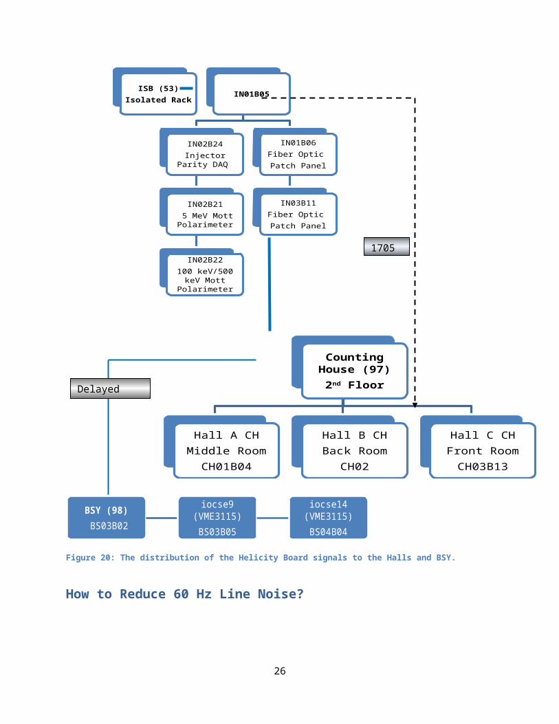
The following diagram shows the fiber distribution from the Injector to the Halls. The distance from the Injector Service Building (ISB) IN01B05 to Hall C was measured to be 1705 ft using the “20 MHz Clock” fiber.
21
ISB (53)Isolated Rack
IN01B05
IN02B24Injector Parity DAQ
IN02B21 5 MeV Mott Polarimeter
IN02B22100 keV/500 keV Mott Polarimeter
IN01B06Fiber Optic Patch Panel
IN03B11Fiber Optic Patch Panel
Counting House (97)
2nd Floor
Hall A CHMiddle Room
CH01B04
Hall B CHBack Room
CH02
Hall C CHFront Room
CH03B13
Delayed Helicity
1705 ft
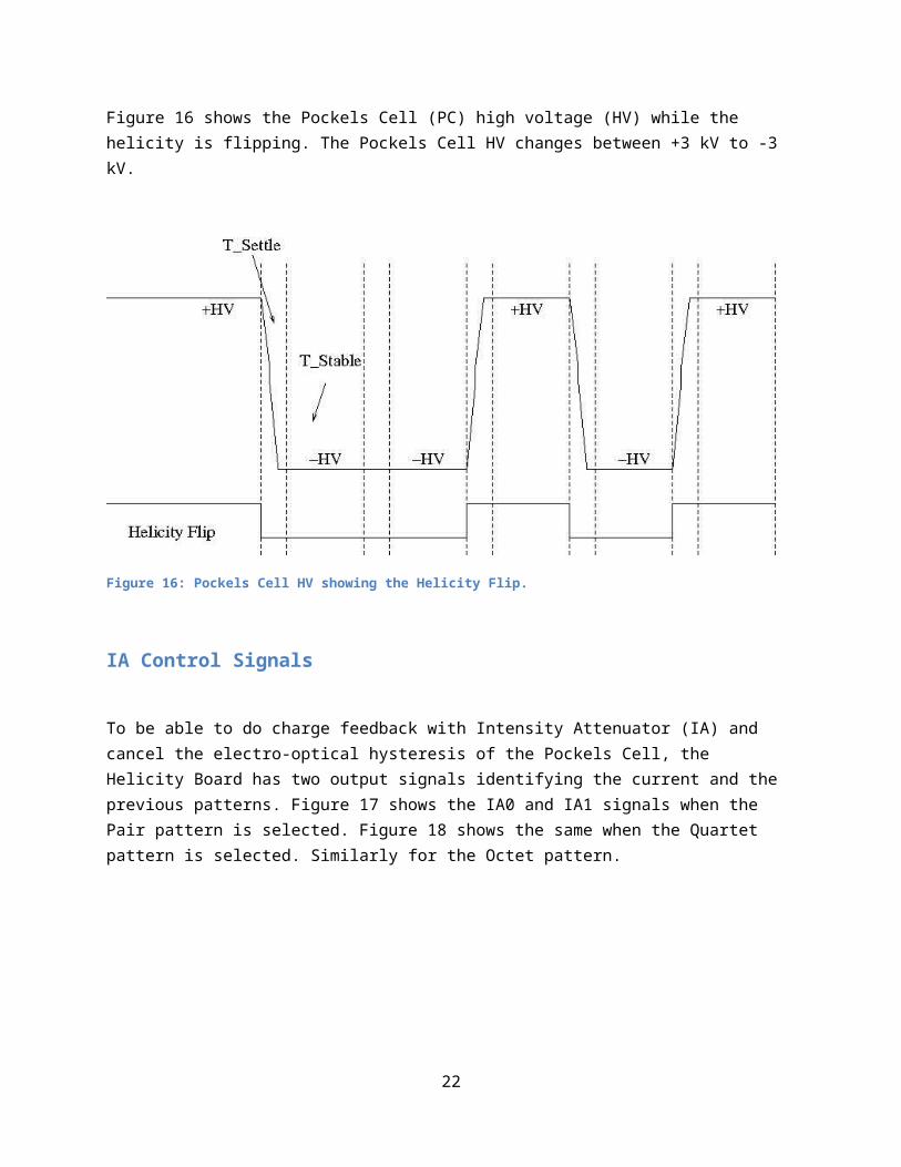
Figure 20: The distribution of the Helicity Board signals to the Halls and BSY.
How to Reduce 60 Hz Line Noise?
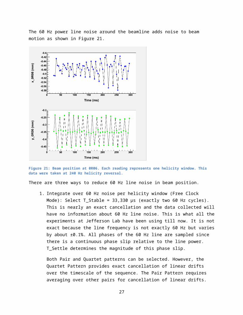
The 60 Hz power line noise around the beamline adds noise to beam motion as shown in Figure 21.
Figure 21: Beam position at 0R06. Each reading represents one helicity window. This data were taken at 240 Hz helicity reversal.
There are three ways to reduce 60 Hz line noise in beam position.
1. Integrate over 60 Hz noise per helicity window (Free Clock Mode): Select T_Stable = 33,330 µs (exactly two 60 Hz cycles). This is nearly an exact cancellation and the data collected will have no information about 60 Hz line noise. This is what all the experiments at Jefferson Lab have been using till now. It is not exact because the line frequency is not exactly 60 Hz but varies by about ±0.1%. All phases of the 60 Hz line are sampled since there is a continuous phase slip relative to the line power. T_Settle determines the magnitude of this phase slip.
22
BSY (98) BS03B02
iocse9 (VME3115)BS03B05
iocse14 (VME3115)BS04B04
Both Pair and Quartet patterns can be selected. However, the Quartet Pattern provides exact cancellation of linear drifts over the timescale of the sequence. The Pair Pattern requires averaging over other pairs for cancellation of linear drifts.
With T_Settle of 500 µs, the helicity reversal rate is 29.56 Hz. Thus the phase of the helicity signals will slip continuously with respect to the power line phase and all phases of power line will sampled every 2.3 seconds.
Figure 22: Phase slip2. Select T_Stable such that: f >1 kHz (Free Clock Mode). This way the Helicity Board frequency is far from the line harmonics. The contribution of the 60 Hz line noise does not change by much from one window to the next and thus cancels when calculating the asymmetries (A). Which pattern is best for cancellation? The data will still have full information about the 60 Hz line noise. This is what QWeak is planning to use.
3. Cancel 60 Hz line noise using patterns: (it does not cancel per window; however it cancels when the asymmetries are calculated).
I. Select 30 Hz Line Sync: Select a T_Settle, then T Stable=33,330µs – T Settle
Select Pair Pattern or Quartet Pattern. If Pair Pattern is selected, then, A=+1−2+1+2
23
This method remains locked to a single phase of the 60 Hz line power instead of sampling all phases as in method (1).
II. Select120 Hz Line Sync: Select a T_Settle, then T Stable=8,330µs – T Settle
Select Quartet Pattern. Then,
A=+1−2−3+4+1+2+3+4
III. Select 240 Hz Line Sync: Select a T_Settle, then T Stable=4,167 µs –T Settle
Select Octet Pattern. Then,
A=+1−2−3+4−5+6+7−8+1+2+3+4+5+6+7+8
In the Line Sync Mode, the start of each pattern is triggered by the Line Sync signal and thus each pattern always starts at the same line phase (line-phase locked). This way the Helicity Board frequency will track the line frequency and the Helicity Board frequency will have the same jitter as the line frequency.
We can also choose to run the above selections in Free Clock Mode. Slowly, the phase of the Helicity Board frequency will drift with respect to the line since the line frequency is not exactly 60 Hz on top of the fact that it has jitter. PREx will run in Free Clock Mode at 240 Hz with the Octet Pattern to cancel line noise.
What about other noises? Choice (2) will work as well for other low frequency noises including the noise from target density fluctuations. This kind of noise is peaked at low frequency because it is a mechanical noise due to gas bubbles in the Hall cryogenic liquid target. Choices (1) and (3) are geared for 60 Hz noise; other noises will not cancel. These noises will increase the width of the helicity correlated distributions as in the case of target density fluctuations. Other prominent single low frequency noises will cause double-horned peak distributions. Figure 23 and Figure 24 show the effect of 50 Hz noise when choosing method (2) or (3). Method (2) is equally effective in cancelling all noises at low frequencies. However, method (3) is geared to 60 Hz and not that effective in cancelling noises at other frequencies. For more details see (Ramsay, 2009).
Figure 23: The effect of a prominent noise at 50 Hz on the asymmetry when the Helicity Board is set to 240 Hz and Octet Pattern. This mode cancels exactly the 60 Hz line noise but very sensitive to other frequencies.
Figure 24: The effect of a prominent noise at 50 Hz on the asymmetry when the Helicity Board is set to 1000 Hz and Quartet Pattern. The effect of 60 Hz line noise is very similar.
Helicity Board Tentative Configuration for PREx and Qweak
24
For testing, PREx will study the 120 Hz helicity reversal as shown in Error: Reference source not found.The tentative Helicity Board configuration for PREx is shown in Error: Reference source not found and for QWeak is shown in Error: Reference source not found. Table 3 shows the Helicity Board configuration.
Table 3: The Helicity Board tentative configuration for PREx and QWeak.
Helicity Board Setting PREx QWeakMode Free Clock Free ClockT_Settle 100 µs 60 µsT_Stable 4,067 µs 900 µsHelicity Pattern Octet QuartetReporting Delay 16 windows 8 windowsHelicity Board Frequency 240 Hz 1042 Hz
Sign of Physics Asymmetry
One may wonder how could we tell the actual helicity of the electrons when they interact with the target in the Hall. Parity Experiments measure very small asymmetries that can easily be positive or negative. There is standard theoretical prediction of the magnitude and sign of the physics asymmetry. However, the new physics that the experiment is trying to measure may be big enough to change the sing of the asymmetry.
This is easy: no need to keep track of all these conventions about helicity and how it is treated at each junction. This is simply done using the Moller Polarimeter in the Hall. The sign of the asymmetry measured in the Hall is decided using the Moller Polarimeter. Moller asymmetry is well understood in theory and the sign of the measured polarization is well known. To check the relative sign between the Moller Polarimeter DAQ and the Parity DAQ, a large charge asymmetry is introduced in the injector by changing the Pockels Cell HV (PITA) and both DAQs measure this charge asymmetry at the same time to find out the relative sign.
Helicity Board Circuit Diagram
Electronic Cross-talk and Ground Loop Elimination in the Injector
25
While performing parity experiments it is vital to prevent electronic cross-talk that could feed real-time helicity information to the outside world. Ground loops could transmit this signal and must be eliminated. Extra effort was spent to make sure the real time helicity signals (Helicity Flip and nHelicity Flip) are isolated. These include:
I. VME Crate of Helicity Control Board is floating and powered with isolation transformer.II. Helicity Board generates two real time helicity signals: Helicity Flip and nHelicity Flip.
Current drawn by board does not depend on helicity state.III. Helicity signal is generated by pseudo-random bit generator. No correlation between
helicity signal and any other signal in Accelerator or in Hall.IV. Outside world receives only Delayed Helicity signal. This signal tells what helicity was in
the past so there is no knowledge of real time helicity.V. Helicity Magnets VME Crate which receives one of the two real time helicity signals
(nHelicity Flip) is also floating and powered by isolation transformer.VI. Real time helicity signal (Helicity Flip) that goes to Laser Hut is isolated. All electronics
that can see real time helicity are floating (next slide).
26
VII. All helicity-correlated beam asymmetries (position, angle, charge, energy, and size – and thus beam scraping) are minimized so helicity is the only real time property of beam that is changing.
VIII. Programming of voltage setpoints of Pockels Cell and IA’s (both receive Helicity Flip signal) in Laser Hut passes through galvanic isolation card and there are no readbacks of these voltages. This card uses a precision isolation amplifier (ISO-124) to isolate signals from -10 V to +10 V with a bandwidth of up to 50 kHz. In the Laser Hut, all circuits seeing real time helicity are floating with respect to earth ground as shown in Figure 25. The option remains to connect a single point ground if needed.
Figure 25: Ground loop elimination in the Injector.
BibliographyRamsay, D. (2009, February 20). False Asymmetry from Fixed-Frequency Noise in the Qweak DAQ. Retrieved from http://qweak.jlab.org/doc-private/ShowDocument?docid=906
27