Embed Size (px)
Citation preview
Henny PennyHeated Holding Cabinet
Model HC 900
SERVICE MANUAL

enn
FMO1-220 Revised 4-01

Henny Penny
LIMITED WARRANTY FOR HENNY PENNY APPLIANCES
Subject to the following conditions, Henny Penny Corporation makes the following limited warranties to theoriginal purchaser only for Henny Penny appliances and replacement parts:
NEW EQUIPMENT: Any part of a new appliance, except lamps and fuses, which proves to bedefective in material or workmanship within two (2) years from date of original installation, will berepaired or replaced without charge F.O.B. factory, Eaton, Ohio, or F.O.B. authorized distributor. Tovalidate this warranty, the registration card for the appliance must be mailed to Henny Penny within ten(10) days after installation.
REPLACEMENT PARTS: Any appliance replacement part, except lamps and fuses, which proves tobe defective in material or workmanship within ninety (90) days from date of original installation will berepaired or replaced without charge F.O.B. factory, Eaton, Ohio, or F.O.B. authorized distributor.
The warranty for new equipment and replacement parts covers only the repair or replacement of the defectivepart and does not include any labor charges for the removal and installation of any parts, travel or other expensesincidental to the repair or replacement of a part.
EXTENDED FRYPOT WARRANTY: Henny Penny will replace any frypot that fails due to manufacturing orworkmanship issues for a period of up to seven (7) years from date of manufacture. This warranty shall not coverany frypot that fails due to any misuse or abuse, such as heating of the frypot without shortening.
0 TO 3 YEARS: During this time, any frypot that fails due to manufacturing or workmanshipissues will be replaced at no charge for parts, labor, or freight. Henny Penny will either install anew frypot at no cost or provide a new or reconditioned replacement fryer at no cost.
3 TO 7 YEARS: During this time, any frypot that fails due to manufacturing or workmanshipissues will be replaced at no charge for the frypot only. Any freight charges and labor costs toinstall the new frypot as well as the cost of any other parts replaced, such as insulation, thermalsensors, high limits, fittings, and hardware, will be the responsibility of the owner.
Any claim must be represented to either Henny Penny or the distributor from whom the appliance waspurchased. No allowance will be granted for repairs made by anyone else without Henny Penny’s writtenconsent. If damage occurs during shipping, notify the sender at once so that a claim may be filed.
THE ABOVE LIMITED WARRANTY SETS FORTH THE SOLE REMEDY AGAINST HENNY PENNYFOR ANY BREACH OF WARRANTY OR OTHER TERM. BUYER AGREES THAT NO OTHER REMEDY(INCLUDING CLAIMS FOR ANY INCIDENTAL OR CONSQUENTIAL DAMAGES) SHALL BEAVAILABLE.
The above limited warranty does not apply (a) to damage resulting from accident, alteration, misuse, orabuse; (b) if the equipment’s serial number is removed or defaced; or (c) for lamps and fuses. THE ABOVELIMITED WARRANTY IS EXPRESSLY IN LIEU OF ALL OTHER WARRANTIES, EXPRESS ORIMPLIED, INCLUDING MERCHANTABILITY AND FITNESS, AND ALL OTHER WARRANTIES AREEXCLUDED. HENNY PENNY NEITHER ASSUMES NOR AUTHORIZES ANY PERSON TO ASSUMEFOR IT ANY OTHER OBLIGATION OR LIABILITY.

Henny Penny Model HC-900
TABLE OF CONTENTS
Section Page
Section 1. INTRODUCTION
1-1. Heated Holding Cabinet .................................................................................. 1-1
1-2. Model Variations .............................................................................................. 1-1
1-3. Features ............................................................................................................ 1-1
1-4. Proper Care ...................................................................................................... 1-2
1-4. Assistance ........................................................................................................ 1-2
1-5. Safety ............................................................................................................... 1-2
Section 2. INSTALLATION
2-1. Introduction ..................................................................................................... 2-1
2-2. Unpacking ........................................................................................................ 2-1
2-3. Location ........................................................................................................... 2-2
2-4. Electrical Connection ...................................................................................... 2-2
2-5. Cabinet Dimensions......................................................................................... 2-3
Section 3. OPERATION
3-1. Introduction ..................................................................................................... 3-1
3-2. Operating Controls and Components .............................................................. 3-1
3-3. Start-Up ........................................................................................................... 3-4
3-4. Operation with Product .................................................................................... 3-5
3-5. Vent Adjustments ............................................................................................. 3-5
3-6. Cleaning Procedures ........................................................................................ 3-5
3-7. Operating Controls 900 and 903 CDT (if applicable) ..................................... 3-7
3-8. Error Codes (CDT Controls) ........................................................................... 3-12
Section 4. TROUBLESHOOTING
4-1. Introduction ..................................................................................................... 4-1
4-2. Troubleshooting ............................................................................................... 4-1
Section 5. MAINTENANCE
5-1. Introduction ..................................................................................................... 5-1
5-2. Test Instruments ............................................................................................... 5-1
5-3. Removal of Module Access Panel ................................................................... 5-1
5-4. Module Removal ............................................................................................. 5-1
5-5. Module Housing Removal ............................................................................... 5-2
5-6. Fuse .................................................................................................................. 5-2
5-7. Power Switch ................................................................................................... 5-3
5-8. Thermostat ....................................................................................................... 5-4
5-9. Indicating Lights .............................................................................................. 5-5
5-10. Thermometer ................................................................................................... 5-5
902 i
Y
ontinue
e
.................................. 5-6 imit ........................................................ 5-7
.......................................... 5-8 ......................................... 5-9
0 W ............................... 5-10 OOW ............................... 5-11 150012000 W ....................... 5-12 3000 W ............................ 5-13
Z, 1612 W ........................ 5-14 60 HZ, 3086W ............................ 5-15 60 HZ, 2000 W ............................ 5-16
12 w ............................ 5-17 2086 W ............................. 5-18
TION ....................................................... 6-1
6.2 . Genuine Parts ...................................................... 6-1 6.3 . How to Find Parts .................................................. 6-1 6.4 . Order ...................................................... 6-1 6.5 . ............................................................. 6-2 6.6 . ........................................................... 6-2 6.7 . .......................................................... 6-2 6.8 . ......................................................... 6-4
enny Penny Distributor ist (Domestic and International)
991

Henny Penny Model HC-900
SECTION 1. INTRODUCTION
1-1 HEATED HOLDING The Henny Penny Heated Holding Cabinet is a basic unit CABINET (HC-900) of food processing equipment designed to hold hot foods at
proper temperature in commercial food operations. Thiscabinet will keep hot foods humid while maintainingtemperature.
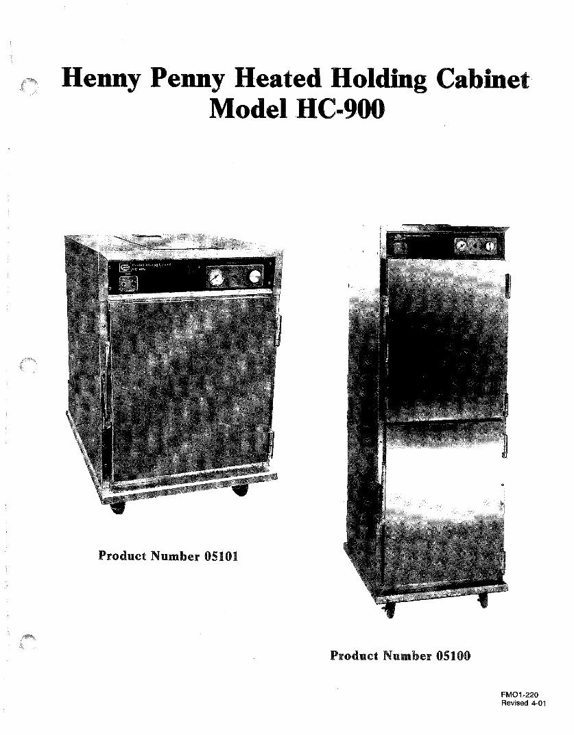
1-2 MODEL VARIATIONS This manual covers the following variations of the HC-900:
Product No. 05100 or 05110 Product No. 05101 or 05111-Full Size Unit -HC-903-4 Doors -120V/1500 Watt-120V/2000 Watt -Vented Module-Right (05100) or -Right (05101) orLeft Hand (05110) Left Hand (05111)Hinged Doors Hinged Doors
Product No. 05102 Product No. 05103-Full Size Unit -HC-903-Features & Options -Features & Options
-Vented Module
Product No. 05203 Product No. 05201-HC-906 -HC-908-Full Size 2 door -Single Door-Vented Module -Vented Module
Some of the instructions and procedures in this manual will notapply to all units.
1-3 FEATURES � Easily Cleaned� Adjustable, Thermostatically Controlled Heat� Lift-off Doors� Easy Access to Electrical Components� Moist Heat� Removable Control Module� Stainless Steel Construction� Full Perimeter Magnetic Door Seals� Lift Out Tray Racks� UL & NSF Listed� Venting System to Limit Humidity Levels in Cabinet (Units with vent adjustment).� Optional Adjustable Legs.� 200 lbs. (91 kgs) Product Capacity
299 1-1

Henny Penny Model HC-900
1-4 PROPER CARE As in any unit of food service equipment, the Heated HoldingCabinet does require care and maintenance. Suggestions for theproper care and maintenance are contained in this manual.
For your convenience, this manual consists of the followingsections:
! Table of Contents! Introduction! Installation! Operation! Troubleshooting! Maintenance! Wiring Diagrams! Part List! Distributor List
The conscientious use of the recommended procedures, coupled withregular maintenance, will result in few repairs to the equipment.When such repairs are required, they may be accomplished by fol-lowing the repair steps contained in this manual.
1-5 ASSISTANCE Should you require outside assistance, just call your local indepen-dent distributor maintained by Henny Penny Corporation.
In addition, feel free to contact our corporate headquarters in Eaton,Ohio. Dial 800-417-8405, or 937-456-8405.
1-6 SAFETY The only way to insure safe operation of the Henny Penny HeatedDisplay Cabinet is to fully understand the proper installation,operation, and maintenance procedures. The instructions in thismanual have been prepared to aid you in learning the properprocedures. Where information is of particular importance or issafety related, the words NOTE, CAUTION or WARNING areused. Their usage is described below:
NOTE
The word NOTE is used to highlight especially important informa-tion.
1-2 299
enny Penny
1-6 SAFETY (Cont.)
0682
The word CAUTION is used to alert you to a procedure that, if not performed properly, may damage the unit.
The word WARNING is used to alert you to a procedure that, if not performed properly, might cause personal injury.
-3


enn y Penny
2-1 ~TRODUCTI SECTION 2. ~ S T ~ L A T I O N
This section provides Henny Penny Heated
installation instructions for the
5
Installation of this unit should be performed only by a qualified service technician.
Do not puncture the skin of the olding Cabinet with drills or screws as component damage or electrical shock could result.
olding Cabinet has been tested, inspected, and expertly packed to insure arrival at its destination in the best possible condition. The cabinet rests on cardboard pads that sit on a wooden skid. The racks inside the cabinet are secured with cardboard packing. The unit is then packed inside a heavy cardboard carton with sufficient padding to withstand normal shipping treatment.
Any shipping damages should be noted in the presence of the delivery agent and signed prior to his or her departure.
To remove the Henny Penny carton, you should:
olding Cabinet from the
1. Carefully cut banding straps. 2. Lift the carton off the unit. 3. Lift the unit off the cardboard padding and skid.
Care should be taken when lifting unit to prevent personal injury. 4. Open doors and remove packing from behind racks. 5 . Peel off any protective covering from the exterior of the
6. Your Heated Holding Cabinet is now ready for location and cabinet.
set up.
Be certain to save any literature that is packed inside the cabinet.
Henny Penny Model HC-900
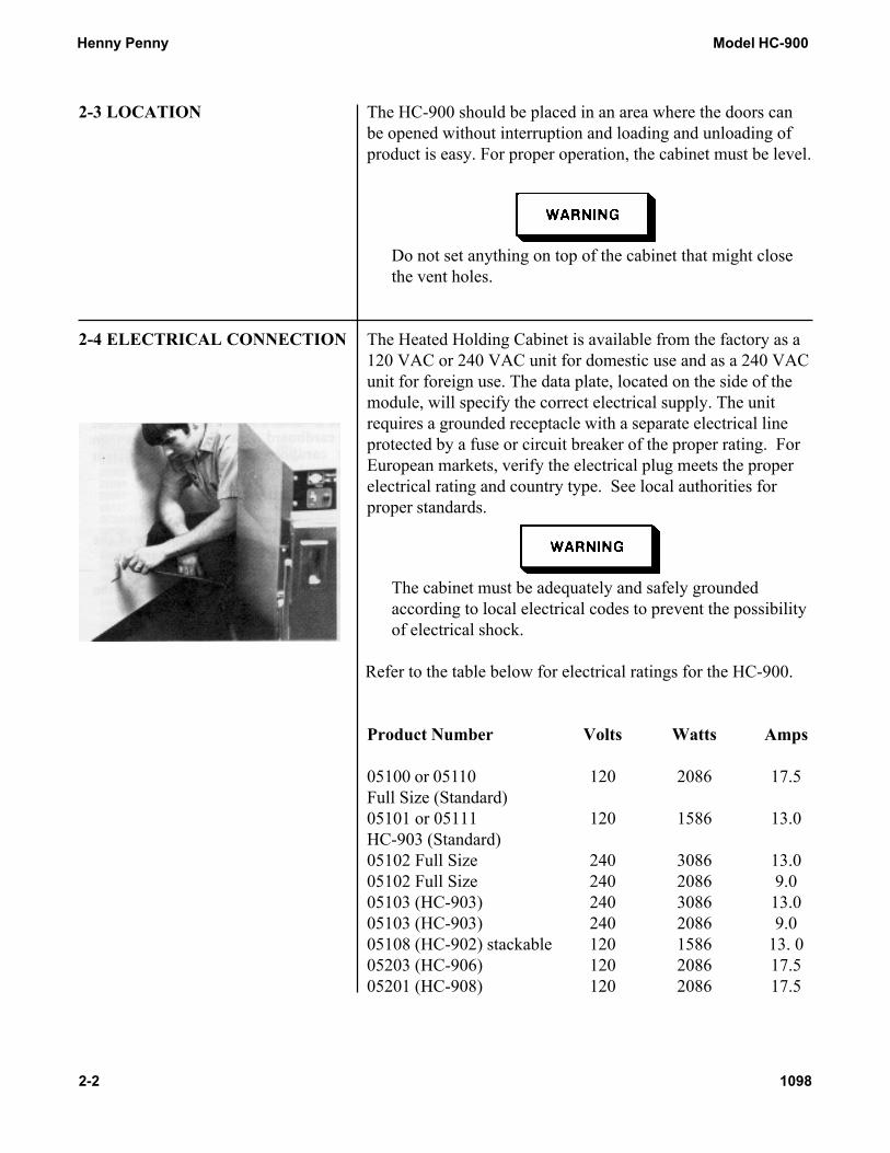
2-3 LOCATION The HC-900 should be placed in an area where the doors canbe opened without interruption and loading and unloading ofproduct is easy. For proper operation, the cabinet must be level.
Do not set anything on top of the cabinet that might closethe vent holes.
2-4 ELECTRICAL CONNECTION The Heated Holding Cabinet is available from the factory as a120 VAC or 240 VAC unit for domestic use and as a 240 VACunit for foreign use. The data plate, located on the side of themodule, will specify the correct electrical supply. The unitrequires a grounded receptacle with a separate electrical lineprotected by a fuse or circuit breaker of the proper rating. ForEuropean markets, verify the electrical plug meets the properelectrical rating and country type. See local authorities forproper standards.
The cabinet must be adequately and safely groundedaccording to local electrical codes to prevent the possibilityof electrical shock.
Refer to the table below for electrical ratings for the HC-900.
Product Number Volts Watts Amps
05100 or 05110 120 2086 17.5Full Size (Standard)05101 or 05111 120 1586 13.0HC-903 (Standard)05102 Full Size 240 3086 13.005102 Full Size 240 2086 9.005103 (HC-903) 240 3086 13.005103 (HC-903) 240 2086 9.005108 (HC-902) stackable 120 1586 13. 005203 (HC-906) 120 2086 17.505201 (HC-908) 120 2086 17.5
2-2 1098

-5. ENS
S tackable
00 05100 and 05110

-906 0. 05203
Model HC-908 Product No. 05201

enny Penny
TRODUCTION
N This section provides operating procedures for the Sections 1 ,2 and 3 should be read, and all instructions should be followed before operating the cabinet.
This section contains an explanation of all controls and components and information on operating procedures and daily maintenance.
__
-2 CONTROL§ NENTS
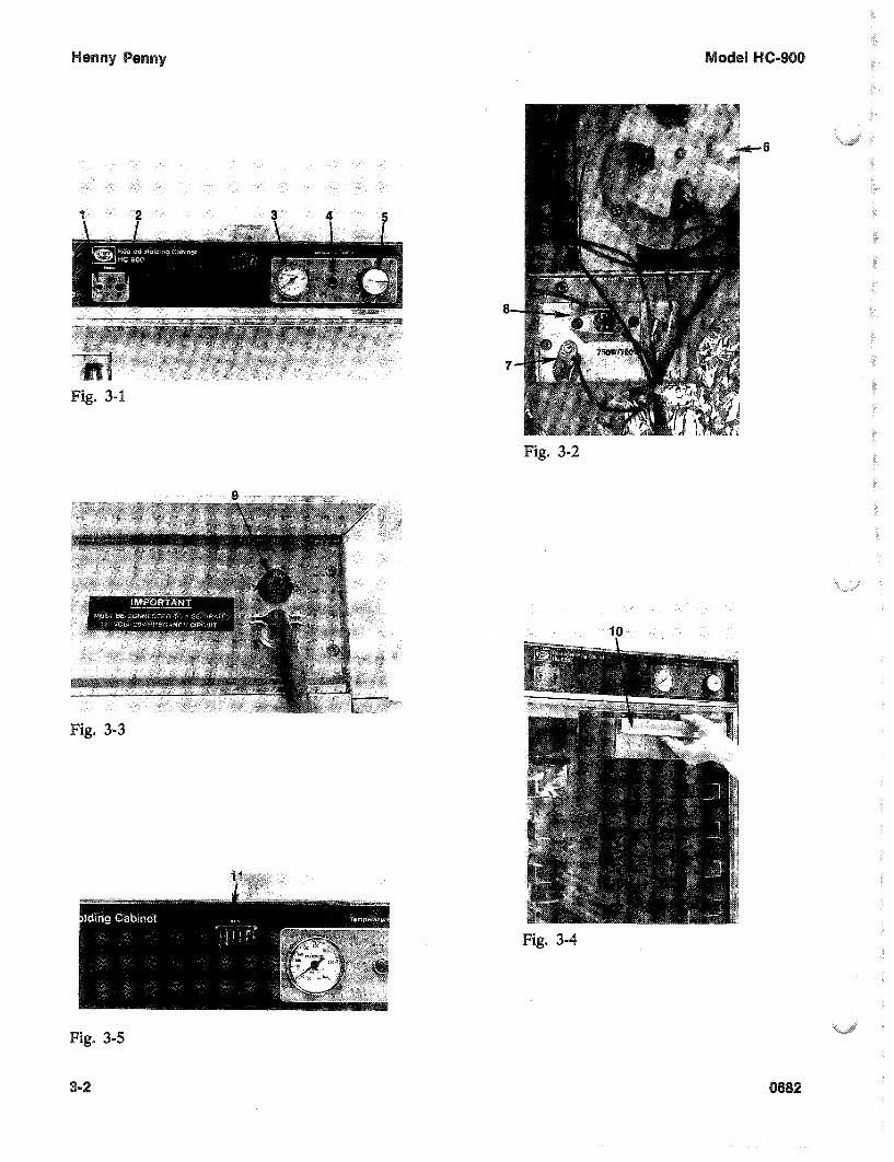
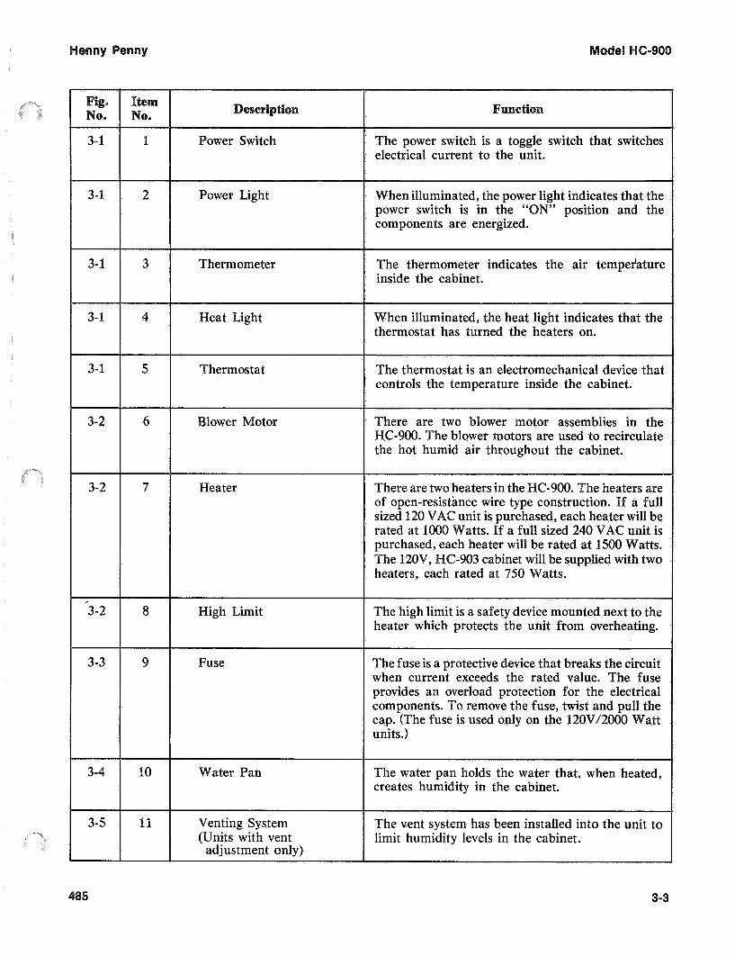
Figures 3-1 through 3-5 identify and describe the functio? of all the operating controls and the major components of the cabinet.
2
d
9"
1
'8
e-90
i eserip
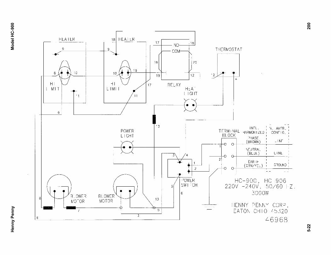
3- 1 Power Switch The power switch is a toggle switch that switches electrical current to the unit.
When illuminated, the pow light indicates that the power switch is in the ‘ N” position and the components are energized.
3-1 2
3 Thermometer The thermometer indicates the air tempeiature inside the cabinet.
3-1
3- 1 4 eat Light When illuminated, the heat light indicates that the thermostat has turned the heaters on.
5 The thermostat is an electromechanical device that controls the temperature inside the cabinet.
3- hermostat
I I
3-2 6 re are two blower motor assemblies in the -900. The blower motors are used to recirculate
the hot humid air throughout the cabinet.
3-2 7 There are two heaters in the of open-resistance wire typ sized 120 VAC unit is purchased, each heater will be rated at 1000 Watts. If a full sized 240 VAC unit is purchased, each heater will be rated at 1500 Watts.
C-903 cabinet will be supplied with two heaters, each rated at 750 Watts.
eater
3-2 8 igh Limit he high limit is a safety device mounted next to the heater which protects the unit from overheating.
3-3 9 he fuse is a protective device that breaks the circuit when current exceeds the rated value. provides an overload protection for the
units.)
o remove the fuse, twist and pull the is used only on the 120V/2000
use
3-4 10 The water pan holds the water that, when heated, creates humidity in the cabinet.
3-5 1 Venting System (Units with vent
The vent system has been installed into the unit to limit humidity levels in the cabinet.
adjustment only)
3-

Stet, 1
Step 2
roper location of water pan.
3-
6-
efore using the olding Cabinet, the unit should be thoroughly cleaned as described in the “Cleaning section of this manual.
1. the HC-900 into operation, move the power switch to N” position. The power light should now be illumi-
nated and the blowers should be in operation.
emove the water pan and put approximately 1” of water in the pan. Return the pan to its location.
e sure to push the water pan in as far as it will go so that it does not block air from the thermometer and thermostat capillary
his will assure proper operation of these components.
3. Set the thermostat at #7 or approximately 180” heat light goes out, the unit is ready for operation.
he unit should take appro temperature during start up goes out before loading with product.
ately 25-35 minutes to heat to sure that the temperature light
2

I Y Y
Step 1
-5
Step 3
1. Place the hot product on bun pans and insert between the cabinet racks.
2. Serve the product first that has been in the cabinet the longest.
3. Open the doors only as necessary to load and unload pro- duct. This will help temperature stay constant and will save energy.
As mentioned in 3-2 of this section, the vent system limits the humidity level of the cabinet. he vent adjustments are very easy to follow.
The vent setting corresponds to the number of trays of product. With one tray of product, set the vent at No. 1. With two trays of product, set the vent at No. 2 and so on.
urn all controls to the " " position.
2. Disconnect the electrical supply to the cabinet.
Allow the unit to cool before cleaning, as the interior of the cabinet may be hot enough to burn.
pen the doors and remove all trays from the cabinet.
4. Take the trays to a sink and clean them thoroughly.
Most surfaces of the Y
soap, and water. D
5. Remove the water pan. Clean the pan with a soft cloth, soap, and water.
Henny Penny Model HC-900
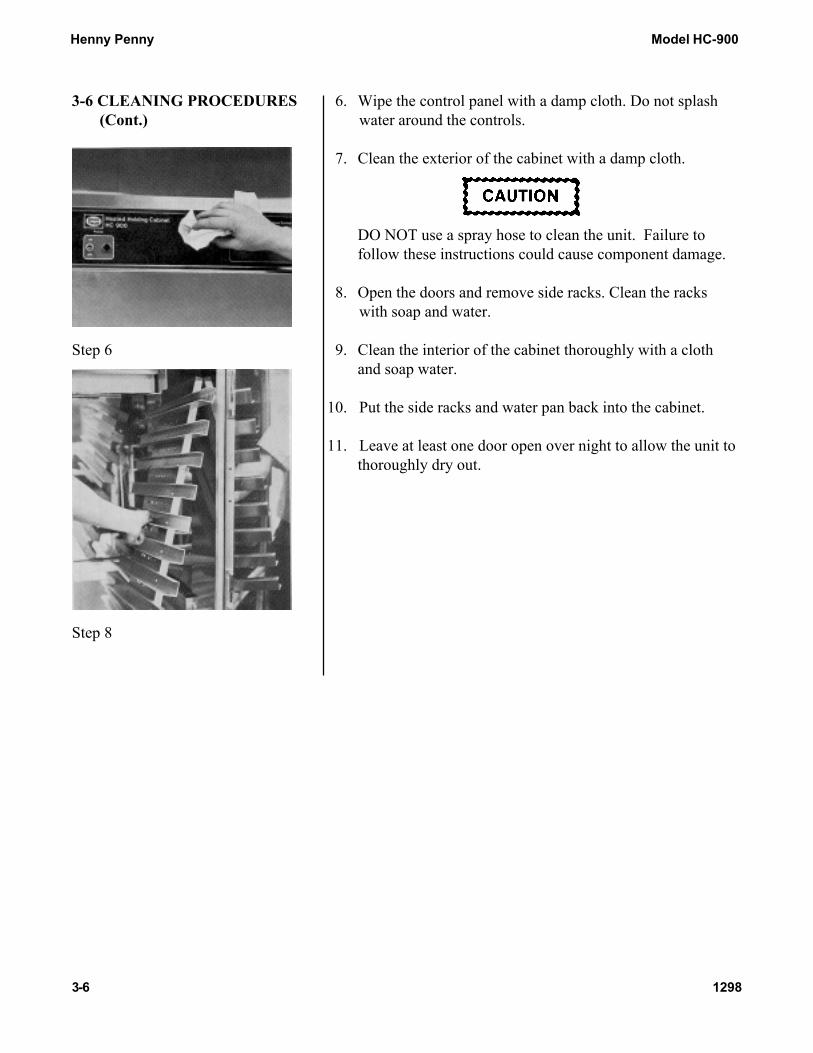
3-6 CLEANING PROCEDURES 6. Wipe the control panel with a damp cloth. Do not splash (Cont.) water around the controls.
7. Clean the exterior of the cabinet with a damp cloth.
DO NOT use a spray hose to clean the unit. Failure tofollow these instructions could cause component damage.
8. Open the doors and remove side racks. Clean the rackswith soap and water.
Step 6 9. Clean the interior of the cabinet thoroughly with a clothand soap water.
10. Put the side racks and water pan back into the cabinet.
11. Leave at least one door open over night to allow the unit tothoroughly dry out.
Step 8
3-6 1298

Henny Penny Model HC-900
3-7. OPERATING CONTROLS These instructions are for both 13 and 5 count down timers.900 and 903 CDT(if applicable) Start-UP
1. Turn the power switch to the ON position.
2. The display shows the increase in temperature, indicating the unitis heating.
3. When the preset temperature is reached, the �HEAT ON� LEDturns off and the display stays at the preset temperature.
Temperature Regulation
1. Press and hold the PROGRAM button.
2. The control beeps and �Prog Enter Code� shows in display.
3. Enter access code 1, 2, 3.
4. Press the INCREASE or DECREASE buttons to change theflashing setpoint temperature.
5. Press and hold the PROGRAM button to set the temperature andexits the programming.
Timer OperationEach of the timers can be started, stopped, or cancelled, and notaffect the status of the other timers.
1. Press the desired timer button.
2. The time remaining shows in the display.
3. At end of time cycle, an alarm sounds and �0:00� is displayed.
4. Press the timer to stop alarm and �---� is displayed.
Press and hold an active timer to cancel.
401 3-7

Henny Penny Model HC-900
3-7. OPERATING CONTROLS Timer Regulation - All timers can be set to a different starting time.900 and 903 CDT(if applicable) 1. Press and hold the PROGRAM button.(Continued)
2. The control beeps and �Prog Enter Code� shows in display.
3. Enter access code 1, 2, 3.
4. Press the PROGRAM button, and �---� is displayed, along withall the timer settings.
5. Press the desired timer and the starting time flashes.
6. Press the INCREASE and DECREASE buttons to change thestarting time.
7. Press the timer button to set the new starting time, and now adifferent timer button can pressed, and it changed.
8. When finished setting timers, press and hold the PROGRAMbutton to exit programming.
NOTEExit the program mode at any time by pressing and holding thePROGRAM button. Also, if no buttons are pressed for twominutes, programming is exited automatically.
Timing Through Power Down
If a power failure occurs while a timer, or timers are running, thecontrols will continue to count down even though the unit has nopower going to it. Once the power comes back on, the timers willshow the correct time remaining and will not have to be reset.
3-8 401

Henny Penny Model HC-900
3-7. OPERATING CONTROLS Special Program Mode - Consists of Setup Mode and Tech Mode.900 and 903 CDT(if applicable) Setup Mode(Continued) � Fahrenheit or Celsius
� Initialize System - One button programming for times andtemperatures
Fahrenheit or Celsius1. Press and hold the PROGRAM button for 4 seconds.
2. �Setup� and �Tech� is displayed.
3. Press a timer button under the word �Setup�.
Ex: Setup Press either 1 or 2.
1 2
4. Enter access code 1, 2, 3.
5. �Setup deg.� �F� is displayed.
6. Press the INCREASE or DECREASE buttons to toggle from�F� (Fahrenheit) and �C� (Celsius).
7. When correct setting displays, press the PROGRAM button tomove to Initialize System, or press and hold the PROGRAMbutton to exit programming.
NOTECE and International units must have the temperature readings inCelsius. Follow above procedures and set to �C�.
Initialize System1. Press and hold the PROGRAM button for 4 seconds.
2. �Setup� and �Tech� is displayed.
3. Press a timer button under the word �Setup�.
Ex: Setup Press either 1 or 2.
1 2
4. Enter access code 1, 2, 3.
5. �Setup deg.� �F� is displayed.
401 3-9
Henny Penny Model HC-900
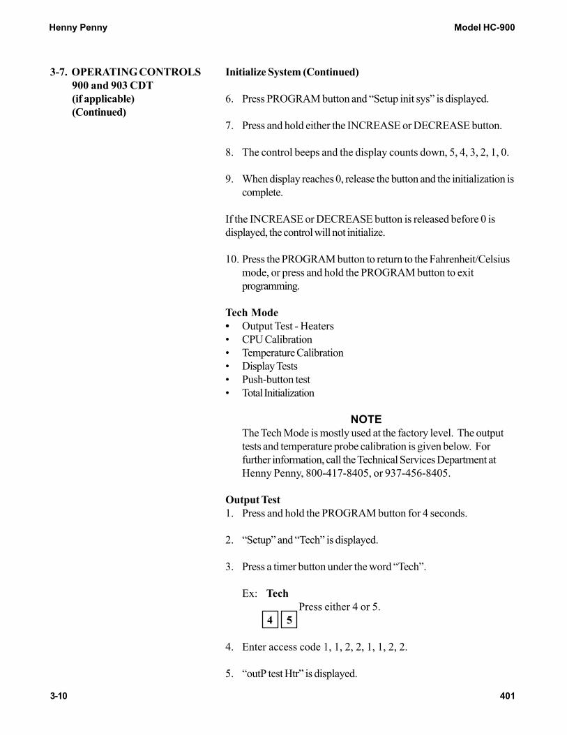
3-7. OPERATING CONTROLS Initialize System (Continued)900 and 903 CDT(if applicable) 6. Press PROGRAM button and �Setup init sys� is displayed.(Continued)
7. Press and hold either the INCREASE or DECREASE button.
8. The control beeps and the display counts down, 5, 4, 3, 2, 1, 0.
9. When display reaches 0, release the button and the initialization iscomplete.
If the INCREASE or DECREASE button is released before 0 isdisplayed, the control will not initialize.
10. Press the PROGRAM button to return to the Fahrenheit/Celsiusmode, or press and hold the PROGRAM button to exitprogramming.
Tech Mode� Output Test - Heaters� CPU Calibration� Temperature Calibration� Display Tests� Push-button test� Total Initialization
NOTEThe Tech Mode is mostly used at the factory level. The outputtests and temperature probe calibration is given below. Forfurther information, call the Technical Services Department atHenny Penny, 800-417-8405, or 937-456-8405.
Output Test1. Press and hold the PROGRAM button for 4 seconds.
2. �Setup� and �Tech� is displayed.
3. Press a timer button under the word �Tech�.
Ex: Tech Press either 4 or 5.
4 5
4. Enter access code 1, 1, 2, 2, 1, 1, 2, 2.
5. �outP test Htr� is displayed.
3-10 401

Henny Penny Model HC-900
3-7. OPERATING CONTROLS Output Test (Continued)900 and 903 CDT(if applicable) 6. Press the 5 timer button (under �Htr�) to turn heat and heat LED(Continued) on and off.
7. Press the PROGRAM button to move to the next step, or pressand hold the PROGRAM button to exit programming.
Temperature Calibration1. Press and hold the PROGRAM button for 4 seconds.
2. �Setup� and �Tech� is displayed.
3. Press a timer button under the word �Tech�.
Ex: Tech Press either 4 or 5.
4 5
4. Enter access code 1, 1, 2, 2, 1, 1, 2, 2.
5. �outP test Htr� is displayed.
6. Press the PROGRAM button 3 times until �CAL OFS Hi Probe185� is displayed.
7. Press and hold number 1 timer (under �CAL�), while pressing theINCREASE and DECREASE buttons and set the display tomatch the actual cabinet temperature.
8. Press the PROGRAM button to move to the next step or pressand hold the PROGRAM button to exit programming.
401 3-11

Henny Penny Model HC-900
3-8. ERROR CODES
(CDT Controls)
The CDT controls have built-in diagnostics which displays
error codes on the display. This section describes the codes.
Displayed Error Code/Warning Problem
“E-4” • Displayed if Control Board exceeds 140o F (60o C).
“E-5” • Displayed if Cabinet air temperature is too hot. Heat relay
locked on? Blower in cabinet not running?
“E-6” • Displayed if the temperature probe fails or is unplugged.
“E-41” • Displayed if PC board memory scrambles. Turn unit OFF
then back ON. If E-41 reappears, replace PC board.
E-50 • Displayed if the RAM inside the CPU chip of the controller
fails. Turn unit OFF then back ON. If E-50 reappears,
replace PC board.
E-51 • Displayed if the NOVRAM chip on controller fails. Turn
unit OFF then back ON. If E-51 reappears, replace PC board.
E-53 • Displayed if the ROM (EPROM) chip on controller fails.
Turn unit OFF then back ON. If E-53 reappears, replace PC
board.
3-12 902

enny Penny
-1 ~TRODUCTIO~ This section provides troubleshooting information in the form of an easy to read list.
If a problem occurs during the first operation of a new cabinet, recheck the installation per section 2 of this manual.
Before troubleshooting, always recheck the operating procedure per section 3 of this manual.
To isolate a malfunction, proceed as follows:
1. Clearly define the problem (or symptom) when it occurs.
2. Locate the problem in the troubleshooting table.
3. Review all possible causes, then, one at a time, work through the list of corrections until the problem is solved.
4. If the problem that you are having is not described in the troubleshooting section of this manual, please call your local distributor maintained by Henny Penny or call Henny Penny Corporation for assistance.
Refer to maintenance procedures in section 5 to check and repair the unit safely and properly.
0682

Tempera- ture
oors are left open.
hermostat set too low.
Gasket torn or wore.
eater not working.
lower not working.
roduct held too long.
Low or improper voltage.
Too much humidity inside the cabinet.
olding product too long.
Vent not set properly. (Units with vent adjustment only).
~
No water in pan.
STE
Faulty thermostat.
aulty high limit.
aulty heater.
aulty wiring.
Keep doors closed except to load and unload product.
ncrease thermostat setting by moving the knob to a higher number setting.
eplace gasket per section 5-14.
Check heater. Replace per sec- tion 5-11.
Check blower. Replace per sec- tion 5-13.
Hold product only for recom- mended time.
Using meter, compare recep- tacle voltage to data plate volt- age.
mpty water from the water pan.
old product for recommend- ed time.
Adjust vent per section 3-5.
Remove pan and put in ap- proximately I” of hot water.
Check thermostat per section 5-8.
Check high limit per section 5-12.
Check heater. Replace per sec- tion 5-11.
Q e c k wiring for loose connec- tions or broken wires and repair as necessary.
5
enny Penny
P R O B L E ~ I CAUSE
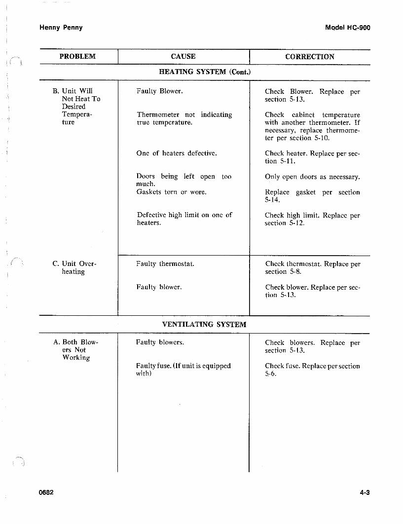
B. Unit Will Not Heat To Desired Tempera- ture
C. Unit Over- heating
A. Both Blow- ers Not Working
EATING SYSTEM (Cont.)
Faulty Blower.
Thermometer not indicating true temperature.
One of heaters defective.
Doors being left open too much. Gaskets torn or wore.
Defective high limit on one of heaters.
Faulty thermostat.
Faulty blower.
Faulty blowers.
Faulty fuse. (If unit is equipped with)
Check Blower. Replace per section 5-1 3.
Check cabinet temperature with another thermometer. If necessary, replace thermome- ter per section 5-10.
Check heater. Replace per sec- tion 5-11.
Only open doors as necessary.
Replace gasket per section 5-14.
Check high limit. Replace per section 5-1 2.
Check thermostat. Replace per section 5-8.
Check blower. Replace per sec- tion 5-13.
Check blowers. Replace per section 5- 13.
Check fuse. Replace per section 5-6.
0682 -3


TENAN~E 5-1
NT
This section provides procedures for the testing and replace- ment of the various parts used within the cabinet. Before replacing any parts, refer to section 4, Troubleshooting. It will aid you in determining the cause of the malfunction.
You may use two test instruments to check the electric components.
1. A Continuity Light 2. An Ohm Meter
When the manual refers to the circuit being closed, the continuity light will be illuminated or the ohm meter should read zero (0) unless otherwise noted.
When the manual refers to the circuit being open, the continuity light will not illuminate or the ohm meter will read one (1) or infinite resistance.
In most procedures of the maintenance section, the access panel must be removed from the top of the module. This access panel can easily be removed by taking out the four screws that fasten it to the module shell.
If the component module of the HC-900 has to be removed, be sure to remove the four screws (one at each corner) before lifting it from the unit. Also, when work has been completed on the module, be sure to relocate it properly and reinstall the screws that fasten the module to the cabinet. Failure to do so might cause the unit to perform inadequately.
2 5-

Y
Ster, 2
Step 3
Step 4
Step 5
5-
Step 2
5-2
f the need for extensive service is required on the module components, the entire outer shell of the module can be removed to make servicing easier. To remove the outer shell of the module, follow these procedures:
emove the module from the cabinet per section 5-4.
2. Remove the six (6) screws that are located on the sides of the module.
3. Remove the four (4) screws located at the corners of the module top.
emove the screws from the control panel and the back panel that fasten them to the module housing.
5. Lift the shell of the module off the unit.
6 . When work is completed, reassemble in reverse order.
All units are not equipped with fuses.
If both blowers quit working at the same time:
1. Remove electrical power supplied to the cabinet.
Place the power switch in the "OFF" position and unplug the power cord. Failure to do so could result in electrical shock.
2. Remove the cap from the fuse holder by turning it counter- clockwise. (Located above the power cord.)
2
C-90
Step 4
-7
Step 3 Tested with switch removed for better illustration.
Step 4
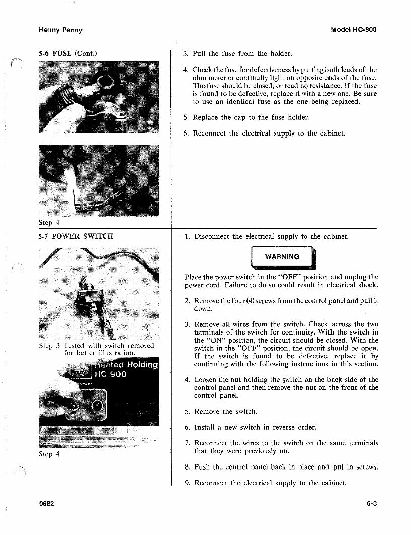
3. Pull the fuse from the holder.
4. Check the fuse for defectiveness by putting both leads of the ohm meter or continuity light on opposite ends of the fuse. The fuse should be closed, or read no resistance. If the fuse is found to be defective, replace it with a new one. Be sure to use an identical fuse as the one being replaced.
5. Replace the cap to the fuse holder.
6. Reconnect the electrical supply to the cabinet.
isconnect the electrical supply to the cabinet.
Place the power switch in the “ F” position and unplug the power cord. Failure to do so could result in electrical shock.
2. Remove the four (4) screws from the control panel and pull it down.
3. Remove all wires from the switch. Check across the two terminals of the switch for continuity. With the switch in the “ON” position, the circuit should be closed. With the switch in the “OFF” position, the circuit should be open. If the switch is found to be defective, replace it by continuing with the following instructions in this section.
4. Loosen the nut holding the switch on the back side of the control panel and then remove the nut on the front of the control panel.
5. Remove the switch.
6. Install a new switch in reverse order.
7 . Reconnect the wires to the switch on the same terminals that they were previously on.
8. Push the control panel back in place and put in screws.
9. Reconnect the electrical supply to the cabinet.
682 5-3

Step 5
Step 7
Step 8
Step 11
isconnect the electrical supply to the cabinet.
lace the power switc ion and unplug the power cord. Failure to do so could result in electrical shock.
emove the access panel from the top of the module.
emove the four (4) screws from the control panel and pull
emove the wires from the thermo at set at the maximum setting (all the
circuit should be closed. With the th
it down.
1 the way counter-clockwise), the circuit should the thermostat is found to be defective, replace
it by continuing with the following instructions in this section.
emove the four (4) nuts that hold the blower box to the cabinet.
ft the blower box up to expose the thermometer and thermostat bulbs.
hile holding the blower box, remove the two (2) nuts that secure the bulb retaining clamps and remove the thermostat bulb from th’e clamps.
8. Using a 5/64’’ Allen wrench, loosen the two (2) set screws in the thermostat knob and remove the knob.
emove the two (2) nuts that hold the thermostat bracket to the control panel.
10. Remove the thermostat shaft extension wit$ a 1/16” Allen wrench.
emove the two (2) screws that hold the thermostat to the bracket.
12. Remove the thermostat from the unit.
13. Install a new thermostat in reverse order.
eposition the blower box and secure it with the four (4) nuts previously removed.
e sure that both the thermometer and thermostat capillary tubes pass through the notches in the front corners of the blower box. Failure to do so could permanently damage the thermometer or thermostat and cause improper operation of the cabinet.
682

(Cont.)
5-
... . .
Step 4
2
6-9
15. Reseal the notches in the blower box corners with silicone rubber sealant.
16. Push the control panel back in place and put in screws.
17. Replace the access panel to the module.
18. Reconnect the electrical supply to the cabinet.
This section should be followed when replacing either of the two (2) indicating lights in the control panel.
isconnect the electrical supply to the cabinet.
Place the power switch in the “ ” position and unplug the power cord. Failure to do so could result in electrical shock.
2. Remove the four (4) screws from the control panel and pull it down.
3. Cut the light wires just behind the body of the light.
emove the light by squeezing the retainers on the body and pushing the light out through the control panel.
nstall a new light by pushing it through the front of the control panel until it snaps securely in place.
6. Strip the ends of the cut wires and connect them to the new light with wire nuts.
7. Push the control panel back in place and put in screws.
8. Reconnect the electrical supply to the cabinet.
isconnect the electrical supply to the cabinet.
” position and unplug the in electrical shock.
5-

- Step 4
Step 6
Step 7
Step 8
6-
2. Remove the access panel from the top of the module.
3. Remove the four (4) screws from the control panel and pull it down.
emove the four (4) nuts that hold the blower box to the cabinet.
5. Lift the blower box up to expose thermometer and ther- mostat bulbs.
6 . While holding the blower box, remove the two nuts that secure the bulb retaining clamps and remove the thermo- meter bulb from the clamps.
emove the two (2) nuts that hold the mounting brackets on the back of the thermometer body.
8. Remove the thermometer by pulling the body and capillary tube through the control panel.
nstall a new thermometer in reverse order.
10. Re-position the blower box and secure it with the four (4) nuts previously removed.
e sure that both the thermometer and thermostat capillary tubes pass through the notches in the front corners of the blower box. Failure to do so could permanently damage the thermometer or thermostat and cause improper operation of the cabinet.
11. Reseal the notches in the blower box corners with silicone rubber sealant.
12. Replace the access panel to the top of the module.
ush the control panel back in place and put in screws,
14. Reconnect the electrical supply to the cabinet.
This section should be followed when replacing either of the two (2) heaters in the cabinet. If there is a heating problem, both heaters should be checked.
0682

I
Step 3
Step 5
Step 6
2
1 . Disconnect the electrical supply to the cabinet.
lace the power switch in the “OFF” position and unplug the power cord. Failure to do so could result in electrical shock.
emove the access panel from the top of the cabinet.
3. Remove the two (2) screws holding the high limit to the heater.
4. Remove the wires attached to the two (2) heater terminals.
5. Remove the two (2) screws holding the heater to the module.
6 . Remove the heater.
7 . Install a new heater in reverse order.
If you have a 240V, 3,000 W unit, you must install the new heater so that the coils are spread furthest apart where air from the blower enters the heater.
8. Reattach the heater wires.
9. Refasten the high limit to the new heater.
10. Replace the access panel to the module.
1 1 . Reconnect the electrical supply to the cabinet.
This section should be followed when replacing either of the two (2) high limits in the cabinet. If there is a heating problem in the cabinet, both high limits should be tested.
1 . Disconnect the electrical supply to the cabinet.
Place the power switch in the “ cord. Failure to do so could result in electrical shock.
” position and unplug the
2. Remove the access panel from the top of the cabinet.
5-

a
Step 4
Step 5
Step 3
Step 4
el
3. Remove the wires attached to the high limit.
4. Check across the high limit terminals for continuity. As long as the cabinet temperature is below 210°F and the blower has been operating properly, the high limit should be closed, or read no resistance. If the high limit is found to be defective, replace it by continuing with the following instructions in this section.
5. Remove the two (2) screws that hold the high limit to the heater.
emove the high limit.
7 . Install a new high limit in reverse order.
8. Reconnect the two wires to the high limit.
9. Replace the access panel to the module.
10. Reconnect the electrical supply to the cabinet.
Procedures for blower motor replacement are the same on both blowers.
1. Disconnect the electrical supply to the cabinet. #
Place the power switch in the “OFF” position and unplug the power cord. Failure to do so could result in electrical shock,
2. Remove the access panel from the top of the cabinet.
3. Remove the three (3) screws that fasten the blower motor to the blower housing.
4. Cut the two (2) blower wires approximately 2” away from the blower.
5. Lift the blower motor and wheel out of the blower housing.
The blower motor can be ordered as an assembly. This will include the motor, the fan, and the wheel. Normally, just the motor would need replacing if found to be defective. If you are just replacing the motor, continue with the following procedures.
6. The fan can be pulled off the shaft of the motor.

enny Penny
(Cont.)
Step 7
Step 8
5-
Step 1
Step 2
2
7. With a 5/64” Allen wrench, loosen the set screw that holds the blower wheel to the motor shaft and remove the wheel.
8. Remove the four (4) screws that hold the blower cover to the motor.
9. Install a new blower motor in reverse order.
10. Be sure to put the spacers back between the blower cover and the motor.
When replacing a blower motor, be sure that the motor coil is positioned away from the heater when reinstalling.
11. Reconnect the two wires to the new blower by stripping the wire ends and fastening with wire nuts.
12. Replace the access panel to the module.
13. Reconnect the electrical supply to the cabinet.
ull the gasket to the side to expose the screws that hold the retainer to the cabinet.
2. Loosen the screws around the full outside perimeter of the gasket.
3. With the screws loose, the gasket should slide out from under the retainer.
4. Remove the gasket and replace with a new one by reversing the above procedures.
5-

4
-4
0
Z3
/ I
J
4
489

'h
)
0
OD
cn
OD
1
I I
I-
_I-
--.

HEATER
@
L I M I T L I M I T
BLOWER MOTOR 1 4
POWER LIGHT
MODEL H C - 9 0 0
HENNY PENNY CORP, EATON OHIO 45320
240V. 50/60 HZ 3086

enny
Pen
ny
d
N
0
/ I
I- I
m
R
-4
4u
m
al
4

HEATER
10
l 1 HEATER
a
7
~ TEMP. PROBE
6 m
RELAY
I
2 20
CONTROL
''BOARDP5
4
1
5
6
I
I NTL . TERMINAL HARMONIZED I N&l?~~: I
PHASE 1 (BROWN) I L INE I
C NUETRAL I LINE
2 (BLUE) C I
- MODEL HC-903M 208/240V. 50/60 HZ
1612 W . HENNY PENNY CORP. EATON O H I O 45320
31 904

HEATER I
L -L
HEATER TEMP. PROBE
I l l
I I 6
c 1
MODEL HC-SOOM 240V. 50160 HZ
7
15
5 18
3086 W . HENNY PENNY GORP. EATON OHIO 45320
#, a, .
HEATER HEATER TEMP. PROBE
20 CONTROL
P 4 ~ ~ ~ ~ ~ F
11
I : 4 1
6
I I
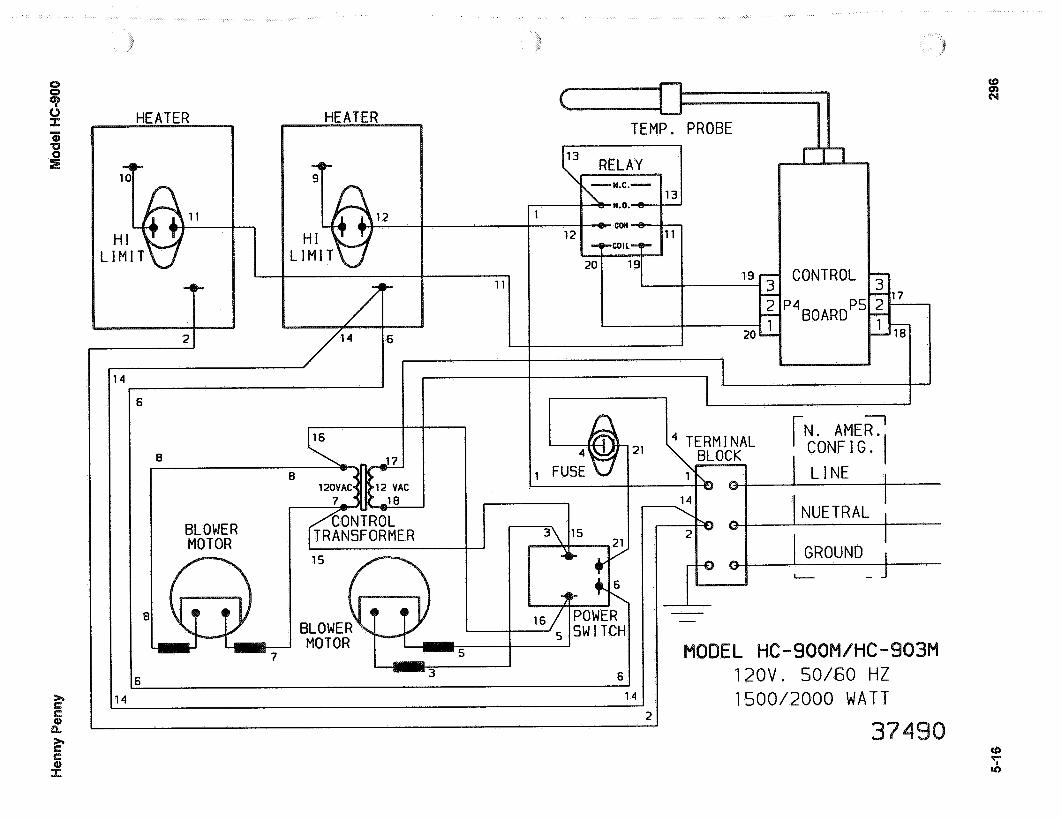
S I 120V. 50/60 HZ 1500/2000 WATT I4 1 4
U 0
1 I
E
BLOWER MOTOR
I
I l l
CONTROL -zj-
P4BOARDP5 2 1 7 1%-
I N . A M E R . ~ CONF I G .
4 TERM I NAL BLOCK 1 L I N E I
1 C
CONTROL f TRANSFORMER
TEMP. PROBE
15
6 2 6
2 INUETRAL I C ! GROUND I ,
3 c - -
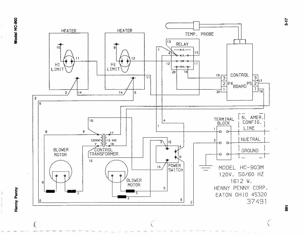
I - - MODEL HC-903M 120V. 50160 HZ
1612 W . HENNY PENNY CORP. EATON O H I O 45320
37491

L r ” I
3
I I
7
TEMP. PROBE
RELAY
2
P 20
CONTROL
’4 BOARDP! ? 18
I I I
I 1 c 1
INTL. TERMINAL HARMONIZED I N&iFF:: I
4 BLOCK 1 1 (BROWN) PHASE I , L I N E
L I N E
C NUETRAL
2 (BLUE) Q
15
6
MODEL HC-9OOM 240V. 50/60 HZ
2086 W . HENNY PENNY CORP. EATON OHIO 45320
37501

I'
HEATER
1
HEATER
F
TEMPERATURE PROBE
SOL STA RE L
I D TE A Y
CONTROL BOARD
L E a3 I 2 % E C a3
21
2 3 GROUND
120V. 50160 HZ 1500/2000
i" 6,

n
I
1
1099
11 I
TEMP. PROBE
RELAY
I
I I
5
E
3
r - -7
I N T L . I N. AMER. I TERM I NAL HARMON I ZED 1 CONF I G. I
I L I N E PHASE I
(BROWN) I B 5 -
NUETRAL I I (BLUE) I L I N E I
-I I
I I
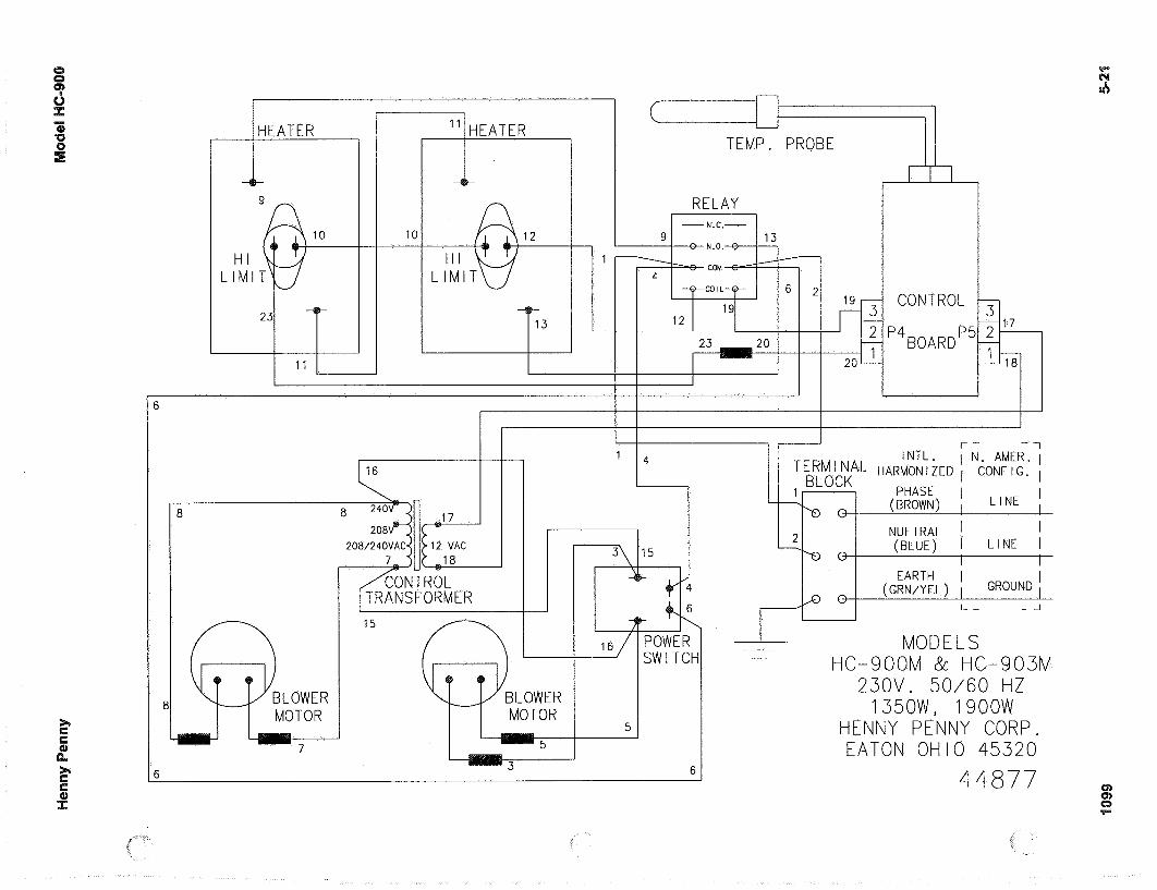
r MODELS
23OV. 50/60 HZ 1350W, 1 9 O O W
HENNY PENNY CORP. EATON OHIO 45320
44877
HC-9OOM & H C - 9 0 3 M I
>r C C
t2 5 1 I
I I
6 P r P)
Hen
ny P
enny
Mod
el H
C-9
00
5-22
200


Henny Penny
LIMITED WARRANTY FOR HENNY PENNY APPLIANCES
Subject to the following conditions, Henny Penny Corporation makes the following limited warranties to theoriginal purchaser only for Henny Penny appliances and replacement parts:
NEW EQUIPMENT: Any part of a new appliance, except lamps and fuses, which proves to bedefective in material or workmanship within two (2) years from date of original installation, will berepaired or replaced without charge F.O.B. factory, Eaton, Ohio, or F.O.B. authorized distributor. Tovalidate this warranty, the registration card for the appliance must be mailed to Henny Penny within ten(10) days after installation.
REPLACEMENT PARTS: Any appliance replacement part, except lamps and fuses, which proves tobe defective in material or workmanship within ninety (90) days from date of original installation will berepaired or replaced without charge F.O.B. factory, Eaton, Ohio, or F.O.B. authorized distributor.
The warranty for new equipment and replacement parts covers only the repair or replacement of the defectivepart and does not include any labor charges for the removal and installation of any parts, travel or other expensesincidental to the repair or replacement of a part.
EXTENDED FRYPOT WARRANTY: Henny Penny will replace any frypot that fails due to manufacturing orworkmanship issues for a period of up to seven (7) years from date of manufacture. This warranty shall not coverany frypot that fails due to any misuse or abuse, such as heating of the frypot without shortening.
0 TO 3 YEARS: During this time, any frypot that fails due to manufacturing or workmanshipissues will be replaced at no charge for parts, labor, or freight. Henny Penny will either install anew frypot at no cost or provide a new or reconditioned replacement fryer at no cost.
3 TO 7 YEARS: During this time, any frypot that fails due to manufacturing or workmanshipissues will be replaced at no charge for the frypot only. Any freight charges and labor costs toinstall the new frypot as well as the cost of any other parts replaced, such as insulation, thermalsensors, high limits, fittings, and hardware, will be the responsibility of the owner.
Any claim must be represented to either Henny Penny or the distributor from whom the appliance waspurchased. No allowance will be granted for repairs made by anyone else without Henny Penny’s writtenconsent. If damage occurs during shipping, notify the sender at once so that a claim may be filed.
THE ABOVE LIMITED WARRANTY SETS FORTH THE SOLE REMEDY AGAINST HENNY PENNYFOR ANY BREACH OF WARRANTY OR OTHER TERM. BUYER AGREES THAT NO OTHER REMEDY(INCLUDING CLAIMS FOR ANY INCIDENTAL OR CONSQUENTIAL DAMAGES) SHALL BEAVAILABLE.
The above limited warranty does not apply (a) to damage resulting from accident, alteration, misuse, orabuse; (b) if the equipment’s serial number is removed or defaced; or (c) for lamps and fuses. THE ABOVELIMITED WARRANTY IS EXPRESSLY IN LIEU OF ALL OTHER WARRANTIES, EXPRESS ORIMPLIED, INCLUDING MERCHANTABILITY AND FITNESS, AND ALL OTHER WARRANTIES AREEXCLUDED. HENNY PENNY NEITHER ASSUMES NOR AUTHORIZES ANY PERSON TO ASSUMEFOR IT ANY OTHER OBLIGATION OR LIABILITY.

enny Penny SECTION 6. PARTS
-1 INTRODUCTION
Product NO. 05100-
Warrantv Exoires Last Dav of
This section identifies and lists the replaceable parts of the Henny Penny Model HC-900 olding Cabinet.
Use only genuine Henny Penny parts in your cabinet. Using a part of lesser quality or substitute design may result in cabinet damage or personal injury.
To find items you want to order from the arts List, proceed as follows:
1. Refer to the photographs in the front of the Operation Sec- tion and the exploded drawings in this section to identify-the part needed.
2. Use the item number from the exploded drawing to locate the corresponding part in the arts List in this section. In this list will be the Henny enny part number and a descrip- tion of the part.
Once the parts you want to order have been found in the ist, write down the following information:
1. From the photograph and Parts
Item Number 44 Part Number 22198
escription ower Switch
2. From the data plate (SA
Product Number 05 100 Serial Number 001 79 Voltage 120
682

c-
he following table has been provided as a sample format for you to use in preparing your spare parts orders. viding all the entries, your distributor will be able t the correct parts will be sent to you. Also, by prepayment your order will be expedited.
-7
Your distributor has a priced parts list and will be glad to inform you of the cost of your parts order.
Commonly replaced items are stocked by your distributor and will be sent out when your order is receive ordered by your distributor from Normally, these will be sent to your distributor within three working days.
All replacement parts (except lamps and fuses) are warranted for 90 days against manufacturing defects and workmanship. If damage occurs during shipping, notify the sender and the carrier at once so that a claim may be properly filed. Refer to warranty in the front of this section for other rights and limitations.
-2 2

Henny Penny Model HC-900
PARTS LISTHC-900, HC-902, HC-903, HC-906, and HC-908
VENTED CONTROL MODULE
1/3 SIZE AND WIDE BODIED UNITS
Item No. Part No. Description Quantity
- 25944 Rear Panel Studweld Assembly 1- 28155 Cable 1- 25964 Hose - Intake 1- 25963 Hose - Exhaust 1- 25977 Hose Clamp 4- 25919 Slide - Vent 1- 25942 Coupling - Hose 1- 25999 Control Panel Stud Assembly 1- 38429 Vent Control Arm 1- 38367 Knob - Vented Module 1
FULL SIZE 900s
- 25942 Coupling Hose 1- 48990 Rear Panel Studweld Assembly 1- 25950 Cable 1- 27927 Spacer - Slide Vent 1- 27828 Slilde - Vent - Back 1- 28092 Slide - Vent - Blower - Box 1- 25964 Hose - Intake 1- 25963 Hose - Exhaust 1- 25977 Hose - Clamp 4
101 6-3

Henny Penny Model HC-900PARTS LIST
HC-900, HC-902, HC-903, HC-906, and HC-908 CONTROL MODULE
Item No. Part No. Description Quantity
1 25704 Panel - Access 151209 Panel -Access - C E 1
2 SC01-053 Screw #8-32 x 1/2 PH RHD 43 48993 Panel - Rear S/A 1
25944 Panel Rear S/A: HC-903 128121 Panel - Rear HC-906; HC-908 149018 Panel - Rear - CE
4 EC04-002 Terminal Flag #10-10-12 Ga. 15 MS01-212 Cable #12/3, 2,000W/120V 8 Ft.
MS01-175 Cable #14/3; Used on 1500W/120Vand 3,000W/240V
28542 Power Cord Assy. - Twist 144857 Power Cord Assy. - CE 126671 Power Cord Assy. - Canada 1
6 25765 Plug 125V, 20 Amp; Used on 2 000W/120V 125764 Plug 125V, 15 Amp, Used on 1500W/120V 127567 Plug 250V, 20 Amp; Used on 3,000W/240V 128543 Plug - Twist 122193 Plug - 120V, 30 Amp - Canada 1
7 SC01-010 Screw #6-32 x 112 pH PHD 28 EF02-007 Fuse 15 Amp 19 26779 Connector - Cable 3/4 110 SC02-023 Screw 48-B x 3/8 pH THD 1511 NS02-001 Nut #10-32 Hex Keps 112 EF02-006 Fuse Holder 113 NS02 005 Nut #6-32 Hex Keps 214 EC01-010 Wire Nut 12-18 Ga 215 25602 Top 1
28153 Top HC-906, HC-908 116 26225 Insulation - Cover 117 SC02-016 Screw #8-AB x 1/2 PH PHD 1818 25620 Seal 219 25670 Cradle 120 25624 Seal 221 25619 Gasket - Blower Outlet 222 25618 Gasket Retainer 223 SC02-012 Screw #12-AB x 3/8 Ph PHD 224 SC01-055 Screw #1 0-32 x 3/4 Hex HD 225 EF02-031 Clamp 1/4 x 3/8� 226 EF02-033 Clamp 7/16 x 3/8� 227 25627 Gasket 228 25616 Box Blower 2
25924 Rear Box - Blower; HC-903 129 NS02-001 Nut #1 0-32 Hex Keps 230 25698 Gasket - Blower Plate 431 25622 Flange - Inlet 232 25623 Housing - Blower 233 25621 Wheel - Blower - Std. 2
52240 Wheel - Blower - lnt�l (larger) 234 SC01-090 Screw #6 32 x 5/16 SL RH 835 LW02-010 Lockwasher - Internal #6 S 836 25632 Plate - Blower 237 25767 Spacer - Motor 838 25751 Motor -Blower 120V 2
25752 Motor -Blower 240V 239 SC01-091 Screw #6-32 x 1 3/4 SL 8
25768 Spacer - Cooling Fan 241 25706 Fan Cooling 3 112 � 242 25759 Heater 120V/1000W 2
25738 Heater 120V/750W 225739 Heater 240V/1 500W 251279 Heater 120V/1000W-CE 251278 Heater 120V/750W-CE 2
43 18201 High Limit Thermostat 243 59272 High Limit Sensor (manual reset)-CE 244 22198 Power Switch 1
43768 Black Rocker Switch - CDT 152224 Rocker Switch - CDT - CE 1
45 16624 Indicator Light 246 14250 Thermometer 147 25863 Knob - Thermostat 148 SC02-030 Screw #8-B x 3/8 PH THD Black Oxide 4
* not shown
Item No. Part No. Description Quantity
49 25717 Label Control Panel 144024 Label Control Panel - KFC 161445 Label Control Panel-Pollo Campero 161523 Label Control Panel-Pollo Campero - 903 125948 Label Control Panel; Std. 900 - Vented 144023 Label Control Panel KFC- Vented 128188 Label Control Panel; HC-906 128190 Label Control Panel; HC-908 133874 Label Control Panel KFC - CDT Vented 145616 Label Control Panel-HC-906 Auto Water-CE 149060 Label Control Panel - CE - Std. 900 161470 Label Control Panel - 903 - Wendy�s 125947 Panel Control S/A HC-903 128182 Panel Control S/A HC 906. HC-908 149054 Panel Control S/A - CE - Std. 900 1
51 25263 Extension Thermostat Shaft 152 25241 Bracket Thermostat Mount 153 14209 Thermostat w/clips 154 25734 Insulation 5 x 7 x 1 255 25733 Insulation 6 x 6 1/2 x 1 456 25735 Insulation 5 x 10 1/2 x 1 257 27124 Access Panel Support 2* 25950 Control Cable; HC 903 1* 27849 Actuator HC-903 1
28-32 25872 Blower Box Assembly 133-41 14249 Blower Motor Assembly 240V 1
25753 Blower Motor Assembly 120V 1* 51214 Vent Housing - CE 2* ME90-009 Relay - 240V - CE 1* 04158 Wiring Kit (higher wattage)-E/M-Top Cord 1* 01460 Wiring Kit (higher wattage)-E/M-Rear Cord 1* 01461 Wiring Kit (higher wattage)-S/S Controls 1
900 CDT Only- 13 Timers* 51040RB Display PC Board Assy; GV083IE and above1* 44741RB Control PC Board Assy; GV083IE and above 1* 31910RB 2 Digit Display Board 1* 40500 Replaceable Beeper-3 Digit 1* 36210 Replaceable Beeper-2 Digit 1* 30954RB 2 Digit Control Board 1
HC 900M - 6 Timers3 37147 Rear Panel Assy. 15 37556 Power Cord Assy. 144 31561 Power Switch 149 31931 Label-Control Panel 150 37395 Control Panel Weld Assy, 153 29523 Probe Assy. 1* 37374RB Display Board Assy. 1* 37367RB Control Board Assy. 1* ME90-003 Relay 12 1* TS22-006 Transformer 115V 1* 28979 Transformer 240V 1* 36210 Replaceable Beeper 1
900 CDT Decals* 33874 KFC Vented 1* 43952 KFC Non Vented 1* 30950 GM 900 1* 31901 903 - 6 Timer 1* 52347 903 - 5 Timer - Gen. Mkt 1
55180 903- Churches 1* 61443 900 Pollo Campero 1
900 CDT-6 Timers-KFC* 51117RB Display PC Board 1* 44741 RB Control PC Board 1* 43073 Control Panel Decal 1* 40500 Replaceable Beeper 1
Boston Market HC-900* 54511 Decal 1* 54571 PC Board Assy. 1* 54577 Temperature Sensor Assy. 1* 30978 Transformer 1* 40645 Relay 1
6-4 101
enny Penny
2
5
Henny Penny Model HC-900
6-6 902
* not shown
PARTS LIST
HC.900, HC.903, HC-906 and HC-908
CABINET ASSEMBLY
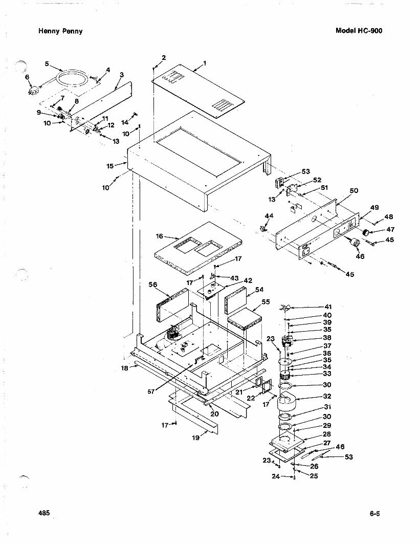
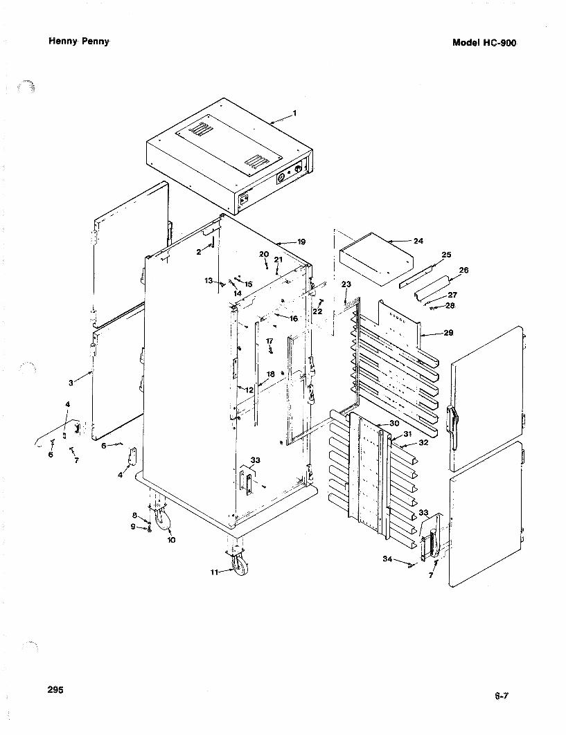
Item No. Part No. Description Quantity
1 31023 Control Module 120V, 2,000W 1
31031 Control Module 120V, 1,500W, HC-903 1
28180 Control Module 120V, 2,000W, HC 906, HC-908 1
2 SC01-092 Screw #10-32 x 3 SL RHD 4
3 28816 Right Hand Top Door Assembly 1
28817 Right Hand Bottom Door Assembly 1
28818 Left Hand Top Door Assembly 1
28819 Left Hand Bottom Door Assembly 1
27033 Right Door Assembly, HC-903 1
27034 Left Door Assembly, HC-903 1
28144 Door Assembly, HC-906 1
28167 Door Assembly, HC-908 1
4 25702 Hinge Assembly 8
6 SC01-086 Screw #10-32 x 3/4 PH TH 16
14271 Door Hinge Screw Kit (4 screws w/o hinge) 1
7 SC01-074 Screw #10-32 x 1/2 PH TH 16
8 LW01-002 Lockwasher Split 1/4” 8
9 SC01-039 Screw 1/4-20 x 1 Hex Head 8
10 27155 Caster 5” 2
11 27154 Caster 5” W/Brake 2
28170 Caster 5" Non-Swivel HC-906, HC-908 2
13 SC01-075 Screw #10-32 x 3/. PHT TH 12
14 25695 Washer 12
15 25644 Spacer 12
16 25687 Retainer, HC-900 and HC-903 8 & 4
28117 Retainer, HC-906; HC-908 8 & 4
17 SC02-016 Screw #8-AB x 1/2 PH PHD 24
18 25689 Retainer, HC-900 8
25690 Retainer, HC-903 4
19 25880 Cabinet Assembly, Complete, less Module 1
25951 Cab. Ass’y Comp., less Module, HC-903 1
28160 Cab. Ass’y Comp., less Module, HC-906 1
28179 Cab. Ass’y Comp., less Module, HC-908 1
20 NS01-008 Nut #8-32 Hex S 10
21 LW02-006 Lockwasher Internal #8 S 10
22 SC01 -053 Screw #8-32 x 1/2 PH RHD 10
23 25643 Gasket Door 4
25793 Gasket - Door, HC-903 4
28147 Gasket - Door, HC-906 2
28143 Gasket - Door, HC-908 1
24 25707 Water Box and Stud Assembly 1
25 25646 Wiper 1
26 25685 Pull 1
27 LW02-005 Lockwasher Internal #10 2
28 NS01-014 Nut Hex #10-32 2
29 27809 Air Duct Assembly - Upper 2
42964 Air Duct Assembly - Upper - 900K ( SIB ) 2
28129 Air Duct Assembly Upper HC-906 2
28128 Air Duct Assembly HC-908 2
52345 Air Duct -Upper-KFC-Int’l-CDT-15 Tray 2
52258 Air Duct Assembly-Upper-KFC-Int’l-13 Tray 2
25956 Air Duct Assembly - HC-903 1
34928 Air Duct Assembly- Upper - Boston Mkt. 2
34550 Air Duct Assembly - Upper - 906- Int’l 2
55181 Air Duct Assembly- Upper- Churches 2
55187 Air Duct Assembly- Lower-Churches 2
55087 Air Duct Assembly- Upper- Wendys 10 Plastic Tray 2
55088 Air Duct Assembly- Lower- Wendys 10 Plastic Tray 2
55084 Air Duct Assembly- Wendys- 903 Plastic Tray 2
Item No. Part No. Description Quantity
30 27811 Air Duct Assembly - Lower 2
34929 Air Duct Assembly-Lower-Boston Mkt. 2
52346 Air Duct-Lower-KFC-Int’l-CDT-15 Tray 2
28130 Air Duct Assembly-Lower HC-906 2
52257 Air Duct -Lower-KFC-Int’l-13 Tray 2
42965 Air Duct Assembly - Lower 900K(SIB) 2
34545 Air Duct Assembly - Lower - 906 Int’l 2
3125696 Hanger 16
32 SC02-023 Screw #8-B x 3/8 PH THD S 8
33 25937 Latch - Magnetic Kasen 171 4
34 SC01-186 Screw #1032 x 13/4 PH 16
14272 Latch Screw Kit (4 screws w/o latch) 1
* 27146 Chrome Hinge Cover 1
* 27912 Handle, HC-906, HC-908 1
* 27939 Brkt. Handle, HC-906, HC-908 2
* 28133 Pan Brkt. Weldment (906 & 908) 22 & 8
* 34949 Door Stop - Boston Mkt. 2 or 4
24-28 25879 Water Box Assembly with Handle 1
* 58275 Hinge Plate (Tap Bar) 900 4
* 58276 Hinge Plate (Tap Bar) 903 4
* 03182 Worktop - HC-903 1
* 56179 Worktop - HC-908 1
Glass Doors Only
* 54353 Glass Door Assembly - 1/3 size(LH) 1
* 54352 Glass Door Assembly - 1/3 size(RH) 1
* 56589 Glass Door Assembly - 1/3 size(RH) 1
less latch and hinges
* 58487 Glass Door Assy-less latch and hinges 1
* 30517 Nut - Glass Retainer 4
* 59257 Glass Door Assy.-Left, Top 1
* 59258 Glass Door Assy.-Left, Bottom 1
* 59260 Glass Door Assy.-Right, Top 1
* 59261 Glass Door Assy.-Right, Bottom 1
Church’s HC-903
* 54353 Glass door Assy(LH w/o Pedal) 1
* 54352 Glass Door Assy(RH w/o Pedal) 1
C.E. Parts
* 43768 Power Switch - Plastic 1
* 49038 Decal - Control Panel - HC 900 1
* 49060 Decal -Control Panel-Vented-HC-903 1
* 49086 Decal - Control Panel - KFC - 900 1
* 49108 Decal -Control Panel-w/Vent - HC-906 1
* 49118 Decal - Control Panel- w/Vent - HC-900 1
* 44857 Power Cord Assembly 1
* 52224 Rocker Switch - CDT - CE 1
enny Penny
I


1. General Services100 Hicks Ave.Medford, MA 02155(800) 233-1033
2. Cole Associates172 Golden StreetIndustrial ParkMeriden, CT 06450(203) 237-7177
3. Globe-Monte Metro, Inc.47-02 Metropolitan AvenueRidgewood, NY 11385(718) 786-5760
4. Guertin Dist. Inc.5 Technology DriveEast Syracuse, NY 13057-9713(315) 437-4928(800) 468-6336
5. Kreiser Distributing Co.13800 Route 30N. Huntington, PA 15642(724) 863-3360
6. AFS Equipment Company9130-X Red Branch RoadColumbia, MD 21045(410) 964-3770(800) 969-3770
7. HP Sales & Service Co.200 Rittenhouse Circle, 5-EastBristol, PA 19007(215) 785-3250NJ Watts (800) 477-4379
8. Astro Food Equipment7901 Old Rockside Rd.Independence, OH 44131(216) 619-8821(800) 367-4237
9. Carlisle Food Systems, Inc.11020 Lakeridge Pkwy.Ashland, VA 23005(804) 550-2169
10. Price-Davis, Inc.3882 East Highway 27Iron Station, NC 28080(509) 928-8815(704) 732-2236(800) 456-1014
11. Big A Distributors, Inc. 1744 Forest Parkway Lake City, GA 30260(404) 366-6510 (800) 222-0298
12. W.H. ReynoldsDistributors, Inc.4824 North Renelli Dr.Tampa, FL 33614(813) 873-2402Miami-(954) 845-0841Jacksonville-(904) 781-9054FL Watts (800) 282-2733
13. Ber-Vel Distributing Co. Inc.7376 Highway 75Pison, AL 35126(205) 681-1855
For Sales or Service Please ContactThe Nearest Henny Penny Distributor
14. Barnett Group2089 York Ave.Memphis, TN 38104(901) 278-0440Nashville, TN(615) 242-6451Scotsman Supply516 5th Ave., SouthNashville, TN 37203(615) 242-6451
15. St. Clair Supply Company231 East Main StreetEaton, OH 45320(937) 456-5500(800) 762-2968
16. Dine Equipment Co.3110 Preston Hwy.P.O. Box 34038Louisville, KY 40232(502) 637-3232FAX (502) 637-5177
17. United Marketing Assoc.11877 Belden CourtLivonia, MI 48150(734) 261-5380
18. T&H Distributors1235 Parkview Rd.Green Bay, WI 54304(920) 339-9838
19. Food Service Solutions, Inc.1682 Barclay Blvd.Buffalo Grove, IL 60089(847) 459-8040(847) 459-7942
20. MEC2511 Cassens Dr.Fenton, MO 63026-2547(636) 343-0664(800) 397-1515
21. Delta Supply Co., Inc.3315 W. Roosevelt Rd.Little Rock, AR 72204(501) 664-4326
22. Dixie Supply490 Julianne St.Bldg. C-1Jackson, MS 39201(601) 354-3025
23. Beaullieu Refrigeration Inc.200 North Luke St.Lafayette, LA 70506(337) 235-9755
24. S.L.E. Corporation1110 Avenue �H� EastSuite 100Arlington, TX 76011(817) 640-7999
25. Brooks Industries4420 S.W. 29th St.Oklahoma City, OK 73119(405) 685-7200
26. B & D Dist.19915 W. 161st St.Suite DOlathe, KS 66062(913) 768-8588FAX 913-768-8855
27. PHT Systems1801 Old Highway 8Suite 120New Brighton, MN 55112(651) 639-0368
28. Mid-Nebraska RestaurantSupply Co.1415 S. Webb RoadGrand Island, NE 68802(308) 384-5780
29. Robert G. Wood & Co.2080 W. Cornell Ave.Englewood, CO 80110(303) 761-0500(800) 358-3061
30. Taylor Restaurant Equip, LLC8307 Central Ave. - NEAlbuquerque, NM 87108(505) 255-9898FAX (505) 255-3279
31. CPE-USALCO1310 West Drivers WayTempe, AZ 85284(480) 496-6995
32. National Equipment Corp.242 West-3680 SouthSalt Lake City, UT 84115(800) 266-5824(800) 955-9202
33. The Nicewonger Co.19219 West Valley HwySuite M103Kent, WA 98032(800) 426-5972FAX (425) 656-0907
34. Tri-State Market Supply11115 E. Montgomery, Suite ASpokane, WA 99206(509) 928-8815(877) 828-4268
36. Western Pacific Distributors, Inc.2368 West Winton Ave. Haywood, CA 94545(510) 732-0100
37. Don Walters Company2121 S. Susan StreetSuite ASanta Ana, CA 92704(714) 979-5863
38. Troyer Foods, Inc.17141 State Route 4 Goshen, IN 46526(219) 533-0302
39. Tri-City HP, Inc.527 West Fourth St. Davenport, IA 52801(319) 322-5382
40. Certified Commercial Service & Equipment (CCSE)6031-A Industrial Heights Drive Knoxville, TN 37909(865)-546-8778
41. Gower Distributors, Inc. 9743 US Highway 87 N. Victoria, TX 77903(361) 573-9777
42. Top-Line Distributors1501 College Ave.Houston, TX 77585(713) 946-6008
43. DSL Inc., Canada14520 128th Ave.Edmonton, AlbertaCanada T5L 3H6(403) 452-7580(Alberta, British Columbia,Manitoba, Saskatchewan,Yukon, & N.W. Territories)
44. Taylor Freezers, Inc.52 Armthorpe Rd.Brampton, OntarioCanada L6T 5M4(905) 790-2211(Ontario, Montreal, andMaritime Provinces)
45. Bazinet Taylor Ltee.4750 Rue BourgVille St. LaurentQuebec, Canada H4T 1J2(514) 735-3627(Quebec only)
If Further Assistance Is Needed Please Contact: Henny Penny Corporation1219 U. S. Route 35 WestEaton, Ohio 453201-800-417-8417Fax 1-800-417-8402 Revised 10/01

U.S. HeadquartersHenny Penny Corporation1219 U.S. Route 35 WestEaton, OH 45320 USATelephone: 937-456-8417Fax: 937-456-1860
Representative Office1 . Henny Penny Corporation
Representative OfficeParc d�Entreprises deI�Esplanade2bis Rue Paul Henri Speak Saint Thibault des Vignes 77462 Lagny sur Mame Cedex, FranceTelephone: 33 (1) 60075600 Fax: 33 (1) 60071489
U.S. Export Centers2. Feco International Company 20
North San Mateo Drive, Suite 9San Mateo, CA 94401 USA Telephone: 415-348-3499Fax: 415-348-3575
3. Caribbean Islands & Central America (excluding Puerto Rico) Total Equipment Suppliers 9550 NW 41st St.Miami, FL 33178Telephone: 305-718-9550Fax: 305-718-9505
Algeria4. SOMAB
Y1 Rue Mahmoud Boudjatit(Oasis) Ager, AlgeriaTel: 213-21-23-3051/3052Fax: 213-21-23-3161
Argentina5. Oditec S.A.
Augstin Alvarez 21281602 FloridaBuenos Aires, Argentina Telephone: (541) 796-0820 Fax: (541) 796-2009
6. AustraliaJ.L. Lennard Pty. Ltd.
937-941 Victoria Rd.West Ryde NSW 2114Sydney, AustraliaTelephone: 61-2-9807-7200Fax: 61-2-9807-7300
Bahrain7. Mohammed Jalal Catering
Old Palace RoadP.O. Box 1335Manama, State of BahrainTelephone: 973-274-800Fax: 973-274-900
Bangladesh8. Puffin International Ltd.
3691B Elephant Rd.Swarankika Plaza4th Floor-Dhaka 1205Dhaka, BangladeshTelephone: 8802-863117Fax: 880-2-867563
Belgium9. Engelen-Heere N.V.
Industrialpark TerbekehofFotografielaan 14B-2610 Antwerpen (Wilrijk)Telephone: 323-825-5577Fax: 323-825-3702
Henny Penny International Distributor Network
Brazil10. Pesin Equipment Food Service
09530-260R. Olavo Bilac 188/198Sao Caetano Do Sul - SPBrazilTelephone:55-11-7690-1470Fax: 55-11-7690-1466
Bulgaria11. E.C.E. - CAIX
23A Rue OborichteSofia 1604, BulgariaTelephone: 19-359-2-946-1479Fax: 19-359-2-946-1669
Chile12. IMAHE
Manuel Montt 1154 ProvidenciaSantiago, ChileTel: 562-341-4953/5707Fax: 562-274-8567
China13. Bonny Foodservice Products
8C Yeung Yiu Chung (No. 8)Industrial Bldg., No. 20Wang Hoi Rd.Kowloon Bay, Kowloon Hong KongTelephone: 852-796-5616Fax: 852-799-8490
Colombia14. Industrial Taylor Ltda.
Transversal 93, Numero 64-24Apartado Aereo 95075Bogota D.E., ColombiaTelephone: 57 (1) 4340016Fax: 571-223-2642
Crotia15. New Rok
Opatija M. Tita 1551410 Opatija, CrotiaTelephohe: 385-51-701-251Fax: 385-51-701-251
Czech Republic17. Citus
Argentinska 20CZ 4170 00 Pragues 7CZECH REPUBLICTelephone: 420-2-667-10-561Fax: 420-2-667-10-557
Denmark18. Inter-Gastro A.S.
Midtager 182605 BrondbyDenmark DK2605Telephone: 45-43292000Fax: 45-43292001
Ecuador19. Equindeca Cia. Ltda.
Hotel El ConquistadorGran Colombia 6-65Cuenca, EcuadorTelephone: 593-7-831788Fax: 593-7-843221
Egypt20. Con Trade Centre
3A Ramsis StreetMaaroof Building #83 & #62Cairo, EgyptTelephone: 20 (2) 770642/762551Fax: 20 (2) 756258
Estonia21. Sisustaja As
Tihniku 511625 Tallinn, EstoniaTelephone: 372-6502300Fax: 372-6502301
Finland22. Monilaite-Dayton Oy
P.O. Box 27Salpakuja 6SF-01200 Vantaa, FinlandTelephone: 358-9-877-0100Fax: 358-9-877-01099
France23. Diffusion International de
Materiel (DIM)Parc d�activite ClemenceauChemin du Chateau d�EauB.P. 400959704 Marcq-En-BaroeuilCedex, FranceTelephone: (33) 20890000Fax: (33) 20727355
Germany24. Sesjak KG
Wullener Feld 9aD-58454 WittenGermanyTelephone: 49-2302-697077Fax: 49-2302-698451
Ghana25. DRT Ghana
E6619 Ablade RoadKanda EstateP.O. Box C2074Accra-Cantonments, GhanaTelephone: 233-2123-3949Fax: 233-2123-1380
Greece26. Domestica S.A.
65 Stournara Str.Athens 10432, GreeceTelephone: 30-15-24-30-14/15Fax: 30-15-22-91-58
Guam27. Pacific Technical Service, Inc.
New Commercial Building#979 Rt. 16, Suite B-3Barrigada, Guam 96913Telephone: 6710632-5000Fax: 671-632-3333
Holland28. Englelen-Heere B.V.
Straatveg 85, Postbus 350203005 DA Rotterdam, HollandTelephone: 311-042-23077Fax: 311-042-23435
Hong Kong29. Bonny Foodservice Products
8C Yeung Yiu Chung (No. 8)Industrial Building #20Wang Hoi RoadKowloon Bay, Kowloon,Hong KongTelephone: 852-796-5616Fax: 852-799-8490
Hungary30. Hotex Service
H-2094 NagykovacsiKossith Lajos u. 1.HungaryTelephone: 36-263-56653/89543Fax: 36-26389463
Iceland31. A. Karlsson H. F. Brautarholti
28105 Reykjavik, PO Box 167 IcelandTelephone: 354-560-0900 Fax: 354-560-0901
India32. AISHWARYA
Trust Complex, 10 OVG Rd BasavanagudiBangalore 560004, India Telephone: 91-80-667-7576 Fax: 91-80-667-7576
Int�l. Refrigeration Corp7 Netaji Subhash Marg Darya GanjNew Delhi 110002, India Telephone: 91-11-3275651 Fax: 91-11-6221827
Indonesia33. P.T. Gema
JL. Raya Bloulevard Raya Block IOA 2 No. 27Kelapa Gading Permai Jakarta 14240, Indonesia Telephone: 62-21-4532077
62-21-4508910 Fax: 62-21-4532586/4530777
Ireland34. Martin Food Equipment Ltd.
Gaskin Business ParkCoes RoadDundalk, Louth County IrelandTelephone: 353-42-30366 Fax: 353-42-30370
Italy35. Allegra SRL
Corso Matteotti, 5 - 10121 Torino, ItalyTelephone: 39-011-540264 Fax: 39-011-533779
Japan36. Toei Kogyo Co. Ltd.
4F, Nissay Nishi-Gotanda Building 24-5Nishi-Gatanda 7-Chome Shinagawa-ku, Tokyo 141-0031 JapanTelephone: 813-3779-1081 Fax: 813-3779-1638
Jordan37. Awar Trading Est
PO Box 962227Amman 11196, Jordan Telephone: 962-6-55-19-610 Fax: 962-6-55-19-605
Korea38. Ohjin Corporation
3rd Floor, Hee Jung Building 1635-0 Seocho-dong Seocho-kuC.P.O. Box 3252Seoul 137-070, Korea Telephone: 82-2-5850441 Fax: 82-2-5874197
Kuwait39. Mabrook Hotel Supplies Co.
PO Box 43832 Hawalli32053 KuwaitTelephone: 965-481-8242
965-483-01648Fax: 965-483-4314
Revised 10/01

Lebanon40. Pro Kitchen
Cahlfoun BuildingKaslik - Main RoadPO Box 1066 JouniehLebanonTelephone: 961-9-635-077Fax: 961-9-635-059
Lithuania41. Master Group Baltic Master
Dariaus Ir Girena 1752038 Vilnius, LithuaniaTelephone: 3702-306-528/529Fax: 3702-306-533
Malaysia42. SCC Corp. Sdn. Bhd.
19-21 Jalan HujanTaman Overseas Union58200 Kuala Lumpur,MalaysiaTelephone: 60-3-77828384Fax: 60-3-77818561
Malta43. C & H Bartoli Ltd.
232 The StrandGzira Gzros, MaltaTelephone: 356-342-584Fax: 356-342-569
Mauritius Island44. (Mauritius, Reunion Island,
Seychelles)Hassam Moussa Rawat10 Bourbon StreetP.O. Box 492Port Louis, Mauritius IslandTelephone: 160 (230) 2080024Fax: 160-230-2080147
Mexico45. Central Mexico Metro Mexico City
Cavimex S.A. de C.V.Revillagigedo No. 61 Col CentroMexico, D.F. 06070MexicoTelephone: 52-5521-4200Fax: 52-5510-2791
NorthCavimex Del Note, SA de C.V.AV Colon 1340 PTE CentroMonterrey, Nuevo LeonTelephone: 52-8372-3888FAX: 52-8372-8948
PacificMicro Herros De Occidente,S.A. de C.V.Av. Juan Palamar y Arias#83 Col. Jardines VallartaZapopan, Jalisco, MexicoC.P.45020Telephone: 52-3629-5405Fax: 52-3673-2943
SoutheastEquipo Para El MercadoS.A. de C.VCalle 55 No. 501-B por 60 y 62Merida, Yucatan,Mexico C.P. 97000Telephone: 52-9923-6500Fax: 52-9928-6649
Morocco46. Electra
Boulevard AHL Loghlam BP 25698Sidi Bernoussi - Ain-Sebaa Casablanca Morocco Telephone: 212-22-753-531 Fax: 212-22-753-554
New Zealand47. Taylor Equipment Limited
4 Ponuz PlaceMt. WellingtonAuckland, New ZealandTelephone: 64 (9) 5733377Fax: 64 (9) 5730841Norway
48. Grillfagmannen A.S.Ostensjoveien 44N-0667 Oslo 6, NorwayTelephone: 47 (2) 651410Fax: 47 (2) 720017
Oman49. Mohsin Haider Darwish LLC
P.O. Box 880Ruwi, Code 112SULTANATE OF OMANTelephone: 968-703411Fax: (968) 789927
Pakistan50. The Equipment Company
Ground Floor, Dadabhoy CentreSharea Faisai, Karachi 75530PakistanTelephone: 922-1-778-1778/2778Fax: 922-1-587-0456/778-2777
Peru51. Importadora Tecnica
Comercial C.R. Ltda.Jr. Marcos de Aramburu #595Lima 17, PeruTelephone: 51-1-226-2124Fax: 51-1-275-2689
Philippines52. HKR Equipment Corp.
2nd Floor, THC Bldg.2176 Primo Rivera St.La Paz, Makati City, PhilippinesTelephone: 632-899-4511Fax: 632-899-4541
Poland53. I. F. E.
Rydygiera 1201 793 Warsaw, PolandTelephone: 48-3912-3373
42-22-663-4820/4069Fax: 48-3912-3373
Portugal54. Restaurotel
Rua FunchalQuinta do Sacouto-Fanquoiro2670-364 LouresPortugalTelephone: 351-219-832-946FAX: 351-219-821-827
Puerto Rico55. Progressive Sales and Service
PO Box 10876Caparra Heights StationSan Juan, Puerto Rico00922-0876Telephone: 787-782-7474Fax: 787-793-6479
Qatar56. Tristar Group
C.R. No. 6778P.O. Box 4746Doha, QatarTelephone: 974-4664433Fax: 974-4365365
Romania57. Delta Technologies Romani S.A.
Sector 6, 20 Constructorilor Blvd.Bloc 20 A, sc. B 7th FloorApt. 64Bucharest, D599 RomaniaTelephone: 401-220-4261Fax: 401-220-3990
Saudi Arabia58. Commercial Center Development
& EconomyP.O. Box 1210Jeddah 21431, Saudi Arabia Telephone: 966 (2) 629-1857 Fax: 966 (2) 629-1860
Senegal59. Breading Systems Co.
C/ Ripoche,1435007 Las PalmasSpainTelephone: 34-9-28-22-43-86 Fax: 34-9-28-27-56-90
Singapore60. Simplex Pte. Ltd.
Block 1, Lorong 8Toa Payoh Industrial Park 01-1383 Singapore 319053Telephone: 65-251-6241Fax: 65-253-8814
Shopfit (S) Pte. Ltd.Blk 623 Aljunied Industrial Complex Unit 02-09Singapore 389835Telephone: 65-7410911Fax: 65-7438911
South Africa61. Foodserv �CC�
PO Box 55269Northlands 2116,Republic of South Africa Telephone: 27 (11) 616-5183, Fax: 27 (11) 616-8287
Spain62. Adisa
Tuset, 8-1008006 Barcelona, Spain Telephone: 34-93-415-0018Fax: 34-93-218-1782
Sri Lanka63. Sperrys Commercial Equipment
1014 Parliament RoadEtul KotteKotte/Colombo, Sri Lanka Telephone:941-873-0561Fax: 941-863-8361
Suriname64. Tessco N.V.
Oude Charlesburgweg #47 Paramaribo Suriname Telephone: 597-473366/477388 Fax: 597-473366
Sweden65. Eurospice AB
Box 5050Hejargatan 6632 29 Eskilstuna, Sweden Telephone: 46 (16) 125600Fax: 46 (16) 131390
Switzerland66. Stuppen Fast Food GmbH
Oberneuhofstrasse 8CH-6340 Baar, Switzerland Telephone: 41-41-761-5052Fax: 41-41 761-7210
Syria67. Lahham Trading & Contracting
Hamra Str. Omyad BuildingP.O. Box 2960Damascus SyriaTelephone: 963-11-331-2251Fax: 963-11-331-2252
Taiwan68. Feco Corporation
420, 11 F Keelung Rd.Sec. 1 Postal Code 110Taipei, TaiwanRepublic of ChinaTelephone:886-2-2758-2288Fax: 886 (2) 2758-2297
Thailand69. Fieco Company Ltd.
43/524-526 Amarinnivej 1Anusaovari LaksiPhaholoyothin RoadBangkok 10220ThailandTelephone: 66-2-521-3824/3878Fax: 66-2-552-0833
Tunisia70. Semci
16, Rue Aziz Taj1101 Tunis RP, TunisiaTelephone: 216 -133-1501Fax: 216-133-0698
Turkey71. Klimatek
Inonu Caddesi, Opera Palas 73/580090 GumussuyuIstanbul, TurkeyTelephone: 90-212-245-181290-212-293-7892Fax: 90-212-293-3903
United Arab Emirates72. Habtoor International
P.O. Box 55332Dubai, United Arab EmiratesTelephone: 971-4-272-1212Fax: 971-4-272-2255
United Kingdom73. Servequip Products Ltd.
214 Purley WayGB-Croyden CRO 4XG, EnglandTelephone: 44-208-6868855Fax: 44-208-6817509
Uruguay74. Tecnoland S.A.
Dr. José Scorsería 2740CP 11300 Montevideo, UruguayTelephone: 598-2-7105900Fax: 598-2-7105900
Venezuela75. Prefer, C.A.
Avenida Presidente MedinaEdificio Prefer, Local No. 44Entre Calles Chile y Progresourb. Los AcaciasCaracas 1040, VenezuelaTelephone: 58-212-633-6933/2801Fax: 58-212-632-6711
Vietnam76. Cao Sinh Pte
Block 1, Lorong 8Toa Payoh IndustrialEstate #01-1383Singapore 319053Telephone: 65-2516241Fax: 84-2538814
Yemen77. Mukiriani Sana�a
PO Box 8150 Sana�aYemenTelephone: 967-1-230-675Fax: 967-1-230-929
Revised 10/01