Embed Size (px)
Citation preview
Content- Online acquisition of the surface temperature at a piston with spot mode- Online high dynamic acquisition of the surface temperature at a piston- Online acquisition of the temperature at the bearing of a connecting rod- High dynamic multi channel load analysis of the connecting rod
Dr. Ernst MannerManner Sensortelemetrie
78549 Spaichingen, Eschenwasen 20www.sensortelemetrie.de
Continuous Acquisition of Measuring Dataup to an Enviromental Temperature of 180°C
(Temperature, Deformation,Pressure between Piston Rings)
File: f:\...\MOTORMESSTECHNIK_EN.cdr // 20110406

Stuttgart
MunichSpaichingen
Berlin
Hannover
Hamburg
Leverkusen
Cologne
Frankfurt
Nuremberg
Who are ?we
78549 SpaichingenEschenwasen 20
Telefon: 07424-9329-0Fax: 07424-9329-29
Email: [email protected]: http://www.sensortelemetrie.de
( about. 90 km south of Stuttgart,near Lake Constance motorway)
* Spezialized company for contactlessmeasuring signal transmission without batteriesat rough environment
* More than ten years of experience
* Patented transmission technique

Powersupply
HF frequency13,56 MHz
Statorantenna
Rotorloop
Patented Energy and Data Transmission(Stator <--> Rotor)
RMC Data / Cal
Energy
Measuring data
Shaft
Demodu-lator
Modu-lator
Sensor Signal Amplifier
Sensor signalamplifier
Receiver
Demo-dulator
Digitizer
Stationary Rotating
Digitalabsorption modulation
How does Sensor Telemetry work ?

Dynamic forcesat the timing chain
Temperature at the surface of the piston
Pressure between piston rings
Dynamic distance betweenpiston and cylinder
Forces at the shoulder bearingof the connecting rod
Load at thecrankshaft
Bearing temperature
Optimation of automotives (engine, gear) bymeasuring the load at moving parts
Measuring Mission at the Engine

Multi Channel Temperature Measurement at the Surface of a Piston
Signal amplifier
Requirements:* Enviromental temperature up to 175°C* Only small modifications at engine components* No feedback* Mechanical strength up to 10,000 rpm* High signal accuracy* Low weight and small size of the measuring technique* Simple mounting* Low mechanical requirement* Unlimited measuring life (without batteries)
Measurement arrangement

State of the Art:
Signal amplifier
Signal amplifier
Measurement with a motion link
Drawbacks:* Feedback to the process* High mechanical requirements* Parting of the cable* Limited measuring time
Measurement with moving coil(method of Essert)
Feedback to the process
High mechanical requirements
Drawbacks:** Signal accuracy* High expenditure** Problem with size
NTC

Applicated Piston
Evaluation Unit
Acquisition of the Surface Temperature at a Piston up to 180°C Ambient Temperature(Spot Measuring Mode, Digital Transmission Technique)
with thermocouples type NiCr.-Ni
21
5,5
10
15
8 channel sensor signal amplifierWeight 3 g
8 channel rotor electronic
Receiving antenna
Rotor antenna
Thermocouple
Contactless energyand data couplingvia crankshaft segment

Piston stroke85 mm
20
Active hight ofthe antenna
Contact angle
Phi = 2*arcos (Piston stroke/2
Piston stroke/2-Active hight of antenna)
= 2 * 58,03° = 116,07°
Contact time = 1(rpm/60)* Phi/360° =
= 2,76 ms at 7000 rpm
Rotational speed =7000 rpm
Receivingantenna
Codition:Contact time > Transmission time: ok
Calculating the Contact Angle Phi:
Calculating the Contact Time:
Transmission time for measuring data: 2,5 ms
= 2 *arcos22,5
42,5
Piston stroke = ca.85 mm
20 t
t
t
t
t
t
t
Pistonstroke
Signal contact
Power supply
on
Channel multiplexerSensor Signal Amplifier
Startchannel1
multiplexed temperaturesignal (electrical)
Temperature signal channel 1(at the telemetry output)
Sampling process perchannel
Rise time T=t1+t2+tk = 1 ms
116°
t1
t2
1
1
2
2
3
3
4
4
5
5
6
6
7
7
8
8Adress unit receiver
Channel multiplex time t = 250 µsk
tk
Signal Transmission
Phi
12
3456
7
8
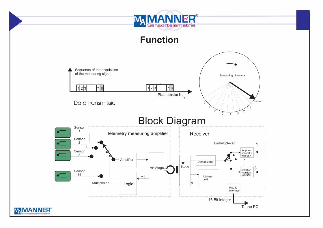
Measuring channel x
t
1 12 23 37 78 8
Sequence of the acquisitionof the measuring signal
Piston stroke No.
Sensor15
Sensor1
Sensor2
Sensor3
.
.
.
Multiplexer
Demultiplexer
Amplifier
HF Stage
HFStage
+1
Telemetry measuring amplifier
Addressunitt
Demodulator
Amplifierchannel 1with S&H
Amplifierchannel 8with S&H
.
.
Receiver
1
8
RS232Interface
To the PC
16 Bit integer
Block Diagram
Build-up
Logic
Function
Data transmission

8 Channel Piston Telemetry(max. ambient temperature =180°C)
Application: Online measurement of the temperatur profil at the piston
Number of channels (total): 8Usable channels: 6(expandable up to 32 channels)1 channel for cold junction1 channel for zero point driftMeasuring range: -40 to +550°CSensor: Thermocouple NiCr-NiIntegrated power supplyMode: 1 measurement per piston stroke
21 x 10 x 5,5 mmMax. acceleration: 25000 gWeight: 3 g
Output signal: 0 to +10 V, (optional RS232)Enviromental temperature: -40 to +180°C max.)Size:
Technical data:
Evaluation unit
Rotor antenna
21
5,5
10
15
8 channel sensor signal amplifierweight 3 g
Piston
8 channel rotor electronic
Receiving antenna
Rotor antenna
Thermocouple

Rotorantenna
Rotorantenna
Piston Piston
Transmission Technology
Sensor signal amplifier Sensor signal amplifier
Stator antennapickup
Stator antennapickup
Variant 1 Variant 2with linear coupler with moving coil

Applicated Piston
8-channel rotor electronic
Receiving antenna
Rotor coil
Thermo couple
To receiver
Contact lessenergy and data transmissionover a shot angle
8-Channelonline Piston Surface Temperature Acquisition
(Spot Mode)with thermocouple Typ NiCr.-Ni
21
5,5
10
15
8 channel sensor signal amplifierweight 3 g
Reiceiver

Sensor Signal Amplifier fixed at theinner side of the piston
Moving coil integratedinto the piston
Stator antenna (pickup)fixed at the engine unit
Cable arrangementthermocouples

Rotor coil
Sensor signal amplifier
Thermocouples
Applicated Piston

Counter weightof crankshaft
Piston
Mounted sensor signal amplifier
Piston of a Car Motor with mounted Sensor Telemetry

Piston of a Car Motor with Mounted Sensor Telemetry
Rotorantenna
Piston
Sensor signal amplifier
Stator antennapickup
With moving coil

Number of channels (total): 16/24/32/48Usable channels: 8/modul(expandable up to 48 channels)1 channel for cold junction1 channel for zero point driftMeasuring range: -40 to +550°CSensor: Thermocouple NiCr-NiIntegrated power supplyMode: 1 measurement per piston stroke
Max. acceleration: 10000 gWeight: 15 g (dependent on channel count)
Output signal: 0 to +10 V, (optional USB, TCP/IP)Enviromental temperature: -40 to +180°C max.)Robust metal housing size:
Technical Data:
Piston of a Ship Motor with mounted Sensor Telemetry
24 channelsensor signal amplifier
Thermo element wire
Piston antenna
8 channel sensor signal amplifierweight 3 g
Number of channels (total): 4/8Usable channels: 6(expandable up to 32 channels)1 channel for cold junction1 channel for zero point driftMeasuring range: -40 to +550°CSensor: thermocouple NiCr-NiIntegrated power supplyMode: 1 measurement per piston stroke
21 x 10 x 5,5 mmMax. acceleration: 25000 gWeight: 3 g
Output signal: 0 to +10 V, (optional TCP/IP, USB)Enviromental temperature: -40 to +180°C max,)Size:
Technical Data:
21
5,5
10
15
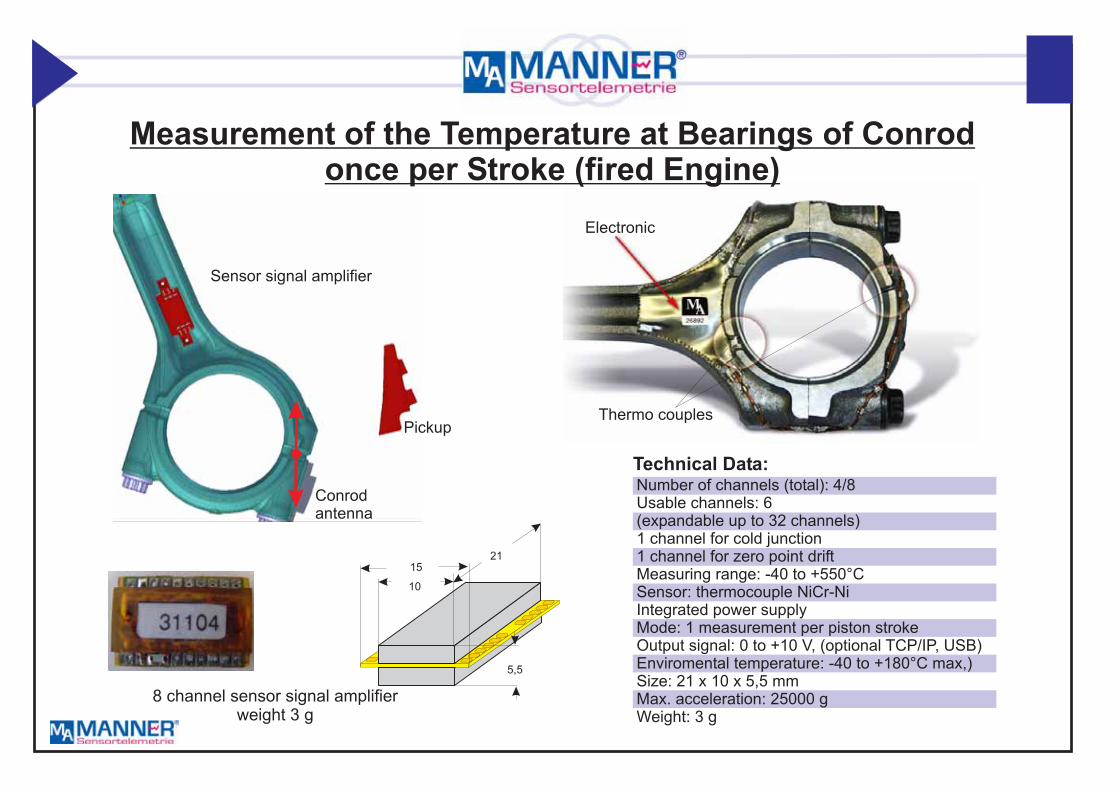
Measurement of the Temperature at Bearings of Conrodonce per Stroke (fired Engine)
Pickup
Sensor signal amplifier
Thermo couples
Conrodantenna
Electronic

Measurement of the Temperature at Bearings of Conrodonce per Stroke (fired Engine)
Number of channels (total): 4/8Usable channels: 6(expandable up to 32 channels)1 channel for cold junction1 channel for zero point driftMeasuring range: -40 to +550°CSensor: Thermocouple NiCr-NiIntegrated power supplyMode: 1 measurement per piston stroke
21 x 10 x 5,5 mmMax. acceleration: 25000 gWeight: 3 g
Output signal: 0 to +10 V, (optional TCP/IP, USB)Enviromental temperature: -40 to +180°C max.)Size:
Technical Data:

Stress Measurement Valve Shaft (Passenger Car)on test rig driven electro engine
Number of channels: 1dynamic strain measurementbandwith: 0 to 50 kHzSensor: strain gaugesIntegrated power supplyOutput signal: 0 to +10 V, (optional TCP/IP, USB)Enviromental temperature: -40 to +160°C max.)Size: D = 22 mm, H = 2,5 mmMax. acceleration: 30000 gWeight: 2 gType: Valve_L_...
Technical Data:
Stator antenna
Load
t
Test rig
Valv
e
Amplifier

Number of channels: 1Spot modeintegrated cold junctionMeasuring range: -40 to +550°CSensor: Thermocouple NiCr-Ni, PT100Integrated power supplyMode: 1 measurement per piston stroke
mm, H = 6 mmMax. acceleration: 25000 gWeight: 3 gT
Output signal: 0 to +10 V, (optional TCP/IP, USB)Enviromental temperature: -40 to +160°C max,)Size: D = 22
ype: Valve_T_....
Technical Data:
Valve Temperatur Measurement on Passenger Car on fired Engine
Movementof the sensor signal amplifier
RG 178200 mm
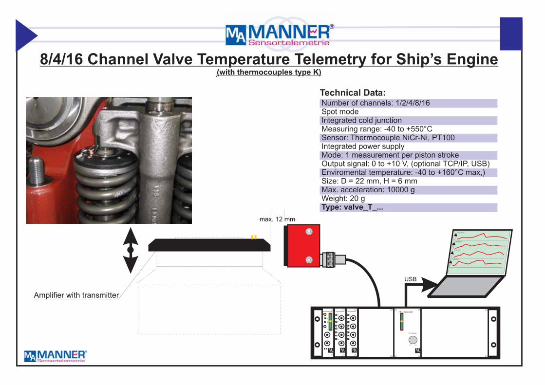
Number of channels: 1/2/4/8/16Spot modeIntegrated cold junctionMeasuring range: -40 to +550°CSensor: Thermocouple NiCr-Ni, PT100Integrated power supplyMode: 1 measurement per piston stroke
mm, H = 6 mmMax. acceleration: 10000 gWeight: 20 g
Output signal: 0 to +10 V, (optional TCP/IP, USB)Enviromental temperature: -40 to +160°C max,)Size: D = 22
Type: valve_T_...
Technical Data:
Amplifier with transmitter
HF - Generator
MA
HF-Leistung
min max
max. 12 mm
8/4/16 Channel Valve Temperature Telemetry for Ship’s Engine(with thermocouples type K)
G
O
Sensortelemetry
MA
G G
G G
G G
G G
O O
O O
O O
O O
Demultiplexer Demultiplexer
M MA A
temperature
temperature
temperature
temperature
USB

Engine Telemetry for High FrequencySignal Acquisition (0 to 10 kHz) in Spot Mode
using Short Time Datalogger(intermitting mode)

Dynamic Position Movement Acquisition with Distance Sensorsbased on Loggtel (on piston mounted short time datalogger, without batteries)
Rotorantenna
Piston
Sensor signalamplifier
Stator antennapickup
Distancesensors
HF - Generator
MA
HF-Leistung
min max
G
O
Sensortelemetry
MA
G G
G G
G G
G G
O O
O O
O O
O O
Demultiplexer Demultiplexer
M MA A
temperature
temperature
temperature
temperature
TCP/IP
Dynamic distance measurement 0 to 0,5 mmMax. length of measurement cycle: 1,5/3/6/12 secNumber of cycles: unlimited (Spotmode)Max. accelaration: 10000gChannel count: 4/8 channelsSensors: distance sensorSampling rate: 40 000/20 000/10 000/5000 sample/sec/channelR
emperature: 0 to 125°C (150°C)Data acquisition via PC (TCP-IP)Integrated time stamp and trigger markType:DATL_....
otational speed: 400 to 8000 RPMEnviromental t
Technical Data:

4 channelsensor signal amplifier
40
10
15
18
Dynamic Load Measurement with Strain Gauges on Pistonbased on Loggtel (on piston mounted short time datalogger, without batteries)
Rotorantenna
Piston
Sensor signalamplifier
Stator antennapickup
Distancesensors
HF - Generator
MA
HF-Leistung
min max
G
O
Sensortelemetry
MA
G GG
G GG
G GG
G GG
O OO
O OO
O OO
O OO
Demultiplexer DemultiplexerDemultiplexer
M MMA AA
temperature
temperature
temperature
temperature
TCP/IP
Dynamic strain measurement with strain gaugesMax. length of measurement cycle: 1,5/3/6/12 secNumber of cycles: unlimited (Spotmode)Max. accelaration: 10000gChannel count: 4/8 channelsSensors:strain gauge/ PT100Sampling rate: 40 000/20 000/10 000 5 000 sample/sec/channelRotational speed: 400 to 8000 RPMEnviromental temperature: 0 to125°C (150°C)Data acquisition via PC (TCP-IP)Tntegrated time stamp and trigger markType: DATL_....
Technical Data:
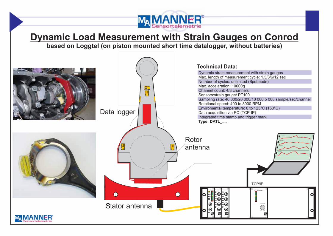
Rotorantenna
Stator antenna
Data logger
Dynamic strain measurement with strain gaugesMax. length of measurement cycle: 1,5/3/6/12 secNumber of cycles: unlimited (Spotmode)Max. accelaration: 10000gChannel count: 4/8 channelsSensors:strain gauge/ PT100Sampling rate: 40 000/20 000/10 000 5 000 sample/sec/channelRotational speed: 400 to 8000 RPMEnviromental temperature: 0 to 125°C (150°C)Data acquisition via PC (TCP-IP)Integrated time stamp and trigger markType: DATL_....
Technical Data:
Dynamic Load Measurement with Strain Gauges on Conrodbased on Loggtel (on piston mounted short time datalogger, without batteries)
HF - Generator
MA
HF-Leistung
min max
G
O
Sensortelemetry
MA
G G
G G
G G
G G
O O
O O
O O
O O
Demultiplexer Demultiplexer
M MA A
temperature
temperature
temperature
temperature
TCP/IP

Rotor antenna
Sensor signal amplifierchannel 1 to 4
Receiving antenna(pickup)
Dynamic Load Measurement with Strain Gauges on Conrod (Ship’s Engine)based on Loggtel (on piston mounted short time datalogger, without batteries)
Dynamic strain measurement with strain gaugesMax. length of measurement cycle: 1,5/3/6/12 secNumber of cycles: unlimited (Spotmode)Max. accelaration 10000gChannel count: 4/8 channelsSensors:strain gauge/ PT100Sampling rate: 40 000/20 000/10 000 5 000 sample/sec/channelRotational speed 400 to 8000 RPMEnviromental temperature: 0 to 125°C (150°C)Data acquisition via PC (TCP-IP)Integrated time stamp and trigger markType: DATL_....
Technical Data:
HF - Generator
MA
HF-Leistung
min max
G
O
Sensortelemetry
MA
G G
G G
G G
G G
O O
O O
O O
O O
Demultiplexer Demultiplexer
M MA A
temperature
temperature
temperature
temperature
TCP/IP

Multi channelSensor Signal
Amplifier
Sensor
Position
Distance
PC
868 MHz
Induktivesupport
13,56 MHz
Radio
0 to ±10V
serial
TCP/IP
90 to 270V AC
Block Diagram (complete System)
Piezo electrical
Rotor electronic
Receiver
Remotecalibration
Optionremote controlfor gain, zero
with
and shunt Cal.
12 bitresolution

Antenna
Transmission mode
Signal contact
time t
time t
Timing
Power SupplySupply
> 2 ms

Measuring mode Measuring modeabout 1,6 s about 1,6 s
Transmission mode Transmission mode
Sampling rate: Measuring mode: 160 kSample/sMemory size: 256 kSample
Transmission mode: Transmission rate 1,67 MBit (100 kSample/s)Contact time about 10% of revolution (72° of the crankshaft)Transmission time about 2,56 s
Mode Cycles

4 channel sensor signalamplifier
Sensor Evaluation unit
µPA/D
converter
A/Dconverter
A/Dconverter
ADconverter
Amplifierwith filter
Amplifierwith filter
Amplifierwith filter
Amplifierwith filter
Memory
Block Diagram Sensor Signal Amplifier
/

Advantage
: - Only one measurement per piston stroke
: - Simple mounting- Less application requirement
Disadvantage
Try to find a continuous measurement methodwith less application requirement
Spot mode:

Rotor antenna
Rotor antenna
Stator antenna
Rotor electronic
Working Mechanism
Measuring points (Thermocouple)
Sensor signalamplifier
Piston

Lowerdead center
Upperdead center
Conditions of Transmission

Dynamic measurement of thepressure between piston rings
Dynamic measurement of thetemperature at the piston
temperature of ignition
Dynamic measurment ofpiston displacement
Force sensorsThermocouples Distance sensors
Depending on the arrangement of the antennas a continuous transmissionof signal data during the whole piston stroke is possible.
On optimal condition of data transmission a data transfer rate of 3,5 MBit ispossible
Useful for
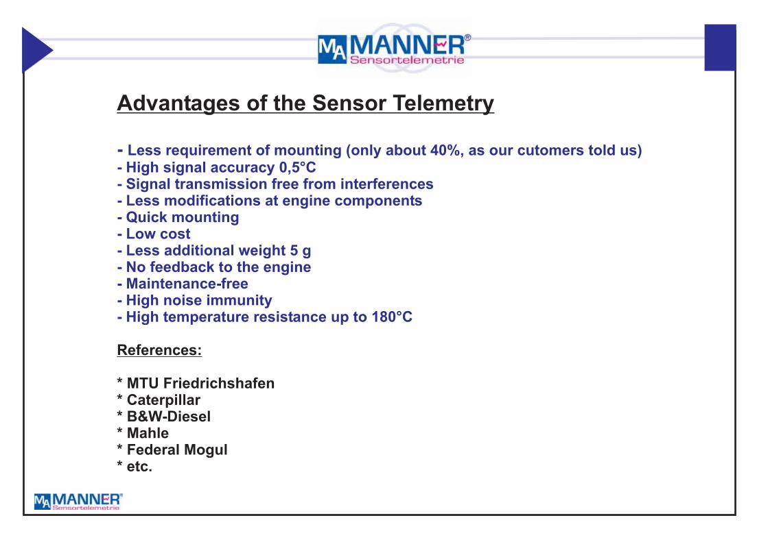
Advantages of the Sensor Telemetry
References:
* MTU Friedrichshafen* Caterpillar* B&W-Diesel* Mahle* Federal Mogul* etc.
- Less requirement of mounting (only about 40%, as our cutomers told us)- High signal accuracy 0,5°C- Signal transmission free from interferences- Less modifications at engine components- Quick mounting- Low cost- Less additional weight 5 g- No feedback to the engine- Maintenance-free- High noise immunity- High temperature resistance up to 180°C

Solutions for furtherEngine Measuring Missions

Signal amplifier
Requirements:* Ambient temperature up to 150°C* Only small modifications at engine components* No feedback* Mechanical strength up to 10,000 rpm* High signal accuracy* Low weight and small size of the measuring technique* Simple mounting* Low mechanical requirements* Unlimited measuring life (without batteries)
High dynamic Multi Channel Analysis of the Load at a Conrod
Strain gageelements

Signal amplifier
Measurement with a motion link
Drawbacks:* Feedback to the process* High mechanical requirements* Parting of the cable* Limited measuring time
State of the Art:

Measuring the Force at the Shoulderof the Connecting Rod
with double Transmission(continuous data transmission)
Evaluation unit(receiver)
Number of channels: 4Transmission: digitalResolution: 12 BitSampling rate: 40 000 data/sec and channelSensor: Strain gage, thermocoupleAccuracy: 0,01 %/°CTemperature: max. 150°C
Technical Data:

Rv
Prog.amplifier
Filterbutterworth
A/D converter
12 Bit
Strain gagebridge
1
n
Convertingrate 40k
Converting0 to 10kHz
Logic /supply
about 3,4 MBit
3,3 V
13,56 MHz
Dig
italm
ultip
lexer
Simultanioussampling
Supply voltagestrain gage bridge
Remoteshunt calibration
Rv
Prog.amplifier
Filterbutterworth
A/D converter
12 BitStrain gagebridge
2
Convertingrate 40k
Converting0 to 10kHz
Rv Rv
Prog.amplifier
Filterbutterworth
A/D converter
12 BitStrain gagebridge
4
Convertingrate 40k
Converting0 to 10kHz
Block Diagram Sensor Signal Amplifier
Piezoelectrical
Thermo-couple
.
.
.
.
.
..
.
.
.

Mode of Transmission
4 channelrotor electronicStator antenna 1
(pickup)
Stator antenna 2
Rotor antenna 1
Rotor antenna 2
To the evaluation unit
Cap piece ofthe bearing
Statorantenna 1
Statorantenna 2
Rotorantenna 1
CrankshaftConrod
Rotorelectronic
Sensor ReceiverRotorantenna 2
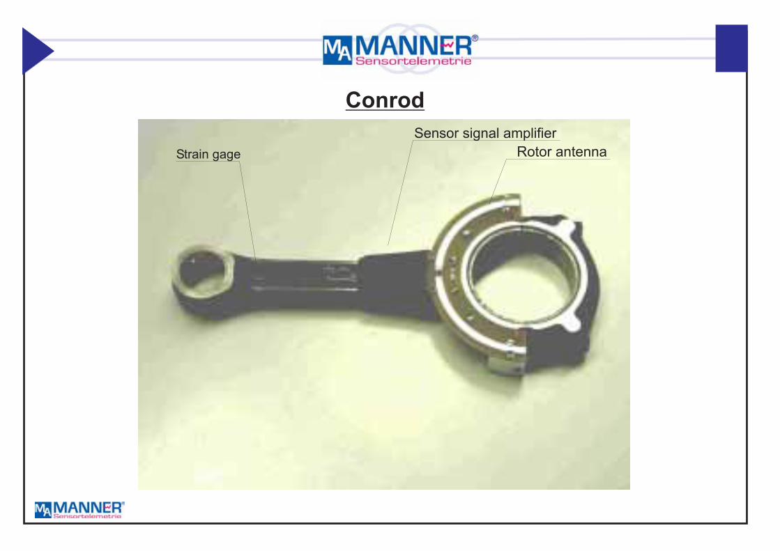
Sensor signal amplifier
Rotor antennaStrain gage
Conrod

To the receiving antenna
Evaluation unit Evaluation unit
Sensor signal amplifierwith integrated antenna
Stator induction loop
Insulation
Strain gage sensor
Prepared chain link
0,1 to 4 mm
Fixing
Rotorelectronic
Strain gagehalf bridge
Measuring Tensile Force at Chain Links
Technical Data:
Transmission principle: inductiveSensor: Strain gage (full and half)Strain gage bridge supply: 6 V
Strain gage resistance: 1000Max. signal bandwidth: 10/20 kHz
�
Energy supply:Integrated into the systemAmbient temperature:-30 to 150° CelsiusWeight sensor signal amplifier(rotor electronic: 5 g)Size: 20 x 21 x 7 mmSignal drift: 0,01 %/°CMax. acceleration: 20,000 gSampling in segments: possibleRise time: 500 µsMax. air gap: 4 mm

8-channel sensorsignal amplifier
8 channel sensorsignal amplifier
Pickup
Receiver
Temperature Acquisition on Clutch with Multichannel Telemetry
.
.
.
.
.
G
O
Sensortelemetry
MA
G G
G G
G G
G G
O O
O O
O O
O O
Demultiplexer Demultiplexer
M MA A
temperature
temperature
temperature
temperature
USB
Technical Data:
Channel count : 8 (time multiplex)
Sampling rate per channel: 2000
Integrated sensor amplifier
Sensors: NiCr.-Ni Thermo couple,
Zero point drift: 0,02 %/°C
Enviromental temperature: -25 to 180°C

PCMPCM16
FM*
4000800040000200000200010000
0,020,010,003
2481216
85125150
total sampling rate
G
O
Sensortelemetry
MA
G G
G G
G G
G G
O O
O O
O O
O O
Demultiplexer Demultiplexer
M MA A Evaluation unit
Evaluation unit
Rotor electronic
Strain gagehalf bridge
Measuring dynamic loads on crankshaft
Technical Data:8 channel sensor telemetrySensors: strain gage (full and half),Thermocouple type KStrain gage bridge supply: 3,3 V
Strain gage resistance: 350Max. signal bandwidth: 5/10/20 kHzEnd of shaft solutionI
�
nductive Energy supply:Ambient temperature:-30 to 160° CelsiusWeight Sensor signal amplifier(rotor electronic: 50 g)Size: Diameter 40, length: 52 mmSignal drift: 0,01 %/°CMax. acceleration: 20,000 goptionsRPM detection (trigger mark)remote controlled gain and zeroadjustment with 12 bit resolution(autozero)
8 channelsensor signal
amplifier
radialpick up
wiring channelinside crankshaft
Type: MSV_RAH_<channels>_<accuracy>_<temp>_<mod>_<sampling rate>
temperature
temperature
temperature
temperature
USB, TCP/IP

Turbo Charger

1 Channel FM Transmitter
ype: MSV_P_D_2_125_FM_...
for dynamic strain gageSensitivity: 0,5 mV/V to 4 mV/VBandwidth: 10 Hz (0) Hz to 40 kHzBrigde supply: 6 VIntegrated filtersResolution: 12 BitsRemote shunt calibrationEnviromental temperature: -25 to 125°C (150°C)Max load: 130,000 gTransmit frequency: 300 to 750 MHzT
Turbo Charger Telemetry (Cylinder Form)

2 Channel PCM Transmitterfor dynamic strain gageSensitivity: 0,5 mV/V to 4 mV/VBandwidth: 10 Hz (0) Hz to 50 kHzBrigde supply: 5 V (3 V)Digital transmission, inductive supply (axial)Time aligned samplingSeparate A/D converterIntegrated filtersResolution: 12 BitsRemote shunt calibrationEnviromental temperature: -25 to 125°C (150°C)Max load: 100,000 gTransmit frequency: 300 to 750 MHzType: MSV_P_D_2_125_Fu_...
12
42
With integrated connector
Car Turbo Charger Transmitter (Cylinder Form)

1/4 Channel PCM Transmitterfor thermocouple and strain gage (torque)Sensitivity: 0,5 mV/V to 20 mV/VBandwidth: 10 Hz (0) Hz to 1 kHzBrigde supply: 3,3 VDigital transmission, inductive supply (axial)Integrated filtersResolution: 16 BitsRemote shunt calibrationEnviromental temperature: -25 to 125°C (160°C)Max speed: 200 000 rpmAxial mounting on shaftType: MSV_P_D_2_125_PCM_...
Car Turbo Charger Transmitters (Cylinder Form), 200 000 rpm
8
35 10

Car Turbo Charger Transmitters (Cylinder Form), 200 000 rpmTorque Measuring at Turbo Charger
Strain gages
Wiring inside the shaft
Sensor signal amplifier
Technical DataTorque range: 0 to 1 NmType of sensor: strain gageAccuracy: 1%Bandwidth 0 to 1 kHzEnviromental temperature: 0 to 150°CBrigde supply: 3,3 VDigital transmission, inductive supply (axial)Integrated filtersResolution: 16 BitsRemote shunt calibrationMax speed: 200,000 rpmTransmitter: axial mounting on shaftType: MW_T_D_1_150_PCM_...

Industrial Turbo Charger Telemetry(1 / 4 / 8/16 channel(s) (multi channel), thermocouple)
4/8/16 Channel PCM Transmitterfor dynamic measurements (strain gage)Minature size: D = 16 mm, L = 30 mmSensitivity: 0,5 mV/V to 4 mV/VBandwidth: 10 Hz (0) Hz to 50 kHzBrigde supply: 3,3 VDigital transmissionIntegrated filtersResolution: 16 BitsRemote shunt calibration
Enviromental temperature: -25 to 125°C (150°C)Max speed: 100,000 RPMMax load: 130,000 gRadio transmitting: 300 to 800 MHzWeight: 30 gT
Remote controlled gain, autozero (option)
ype: MSV_P_D_4_125_Fu_...
Features

Rv
Rv
Rv
Prog.amplifier
Prog.amplifier
Prog.amplifier
Filterbutterworth
Filterbutterworth
Filterbutterworth
A/D converter
A/D converter
A/D converter
12 Bit
12 Bit
12 Bit
Strain gagebridge
Strain gagebridge
Strain gagebridge
1
2
8
Samplingrate 100/200k
Samplingrate 100/200k
Samplingrate 100/200k
Sampling
Sampling
Sampling
0 to 25 (50) kHz
0 to 25 (50) kHz
0 to 25 (50) kHz
Logic
About 13 MBbit
Dig
italm
ultip
lexer
Isochronous sampling
Remoteshunt calibration
Remoteshunt calibration
Remoteshunt calibration
Channel 1
Channel 2
Channel 8
Powersupply
Powersupply
Powersupply
PCM Telemetry for Turbine / Turbo Charger ApplicationBlock diagram module (8 channel transmitter, high speed)
Backbone

Rotor electronic
Rotor antenna(pickup)
16 Channel PCM Transmitterfor thermocouple type K, static strain gageRange: -50 to 1,000°CTime multiplexBrigde supply: 5 VBandwidth: 0 to 20 HzQuasi isolated inputs12 Bit A/D ConverterIntegrated filtersResolution: 12 BitsRemote shunt calibrationEMax load: 100,000 gTransmit frequency: 300 to 750 MHzType: MSV_M_T_16_125_Fu_...
nviromental temperature: -25 to 125°C (150°C)
Telemetry Application on an Industrial Turbo Charger