Embed Size (px)
Citation preview
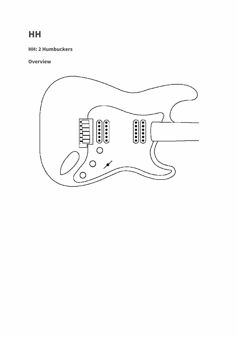
HH HH: 2 Humbuckers
Overview
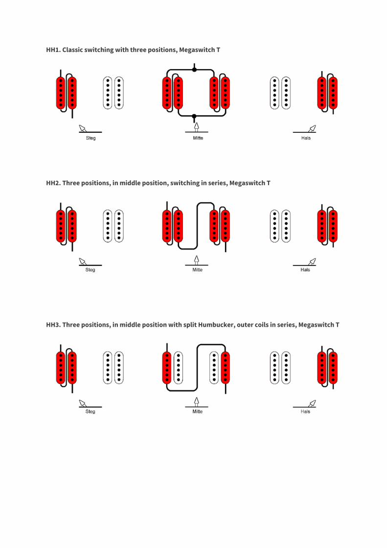
HH1. Classic switching with three positions, Megaswitch T
HH2. Three positions, in middle position, switching in series, Megaswitch T
HH3. Three positions, in middle position with split Humbucker, outer coils in series, Megaswitch T
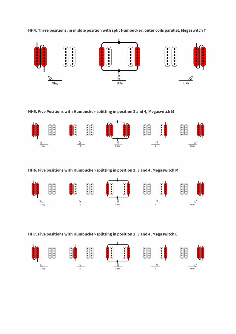
HH4. Three positions, in middle position with split Humbucker, outer coils parallel, Megaswitch T
HH5. Five Positions with Humbucker-splitting in position 2 and 4, Megaswitch M
HH6. Five positions with Humbucker-splitting in position 2, 3 and 4, Megaswitch M
HH7. Five positions with Humbucker-splitting in position 2, 3 and 4, Megaswitch E
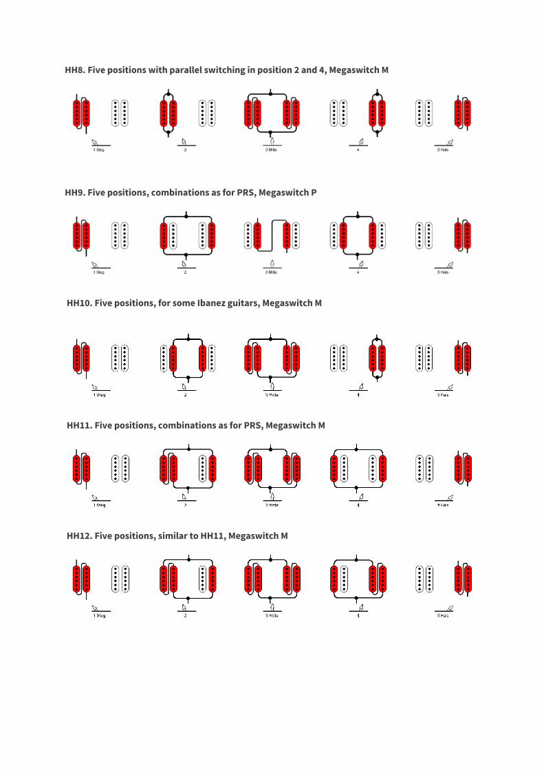
HH8. Five positions with parallel switching in position 2 and 4, Megaswitch M
HH9. Five positions, combinations as for PRS, Megaswitch P
HH10. Five positions, for some Ibanez guitars, Megaswitch M
HH11. Five positions, combinations as for PRS, Megaswitch M
HH12. Five positions, similar to HH11, Megaswitch M
Detail drawing
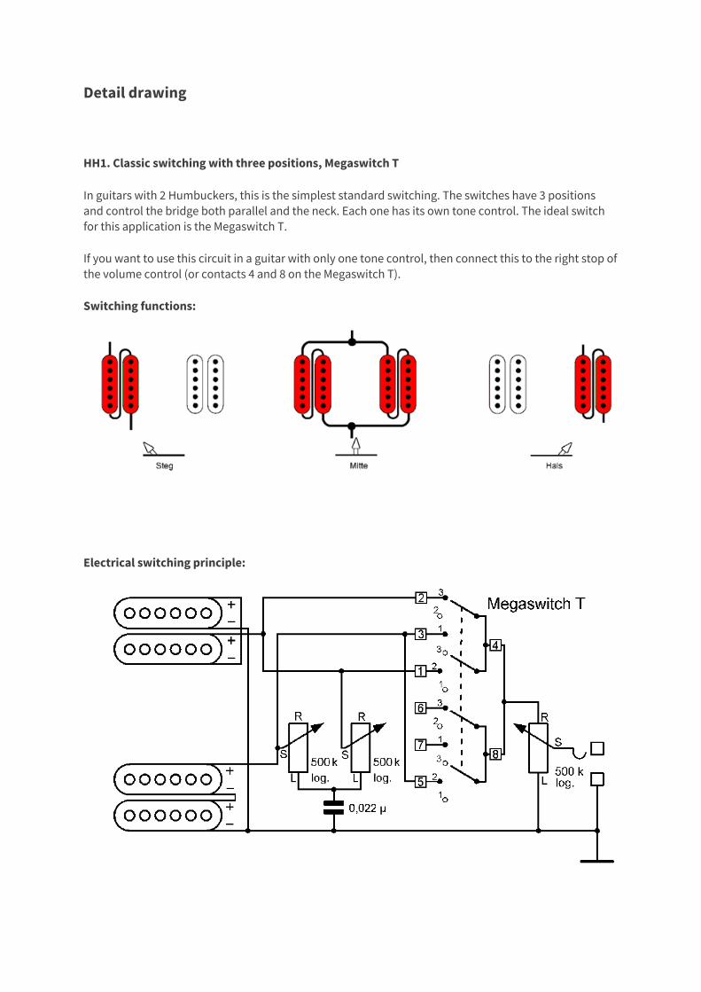
HH1. Classic switching with three positions, Megaswitch T
In guitars with 2 Humbuckers, this is the simplest standard switching. The switches have 3 positions and control the bridge both parallel and the neck. Each one has its own tone control. The ideal switch for this application is the Megaswitch T.
If you want to use this circuit in a guitar with only one tone control, then connect this to the right stop of the volume control (or contacts 4 and 8 on the Megaswitch T).
Switching functions:
Electrical switching principle:
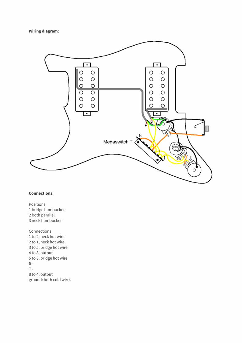
Wiring diagram:
Connections:
Positions 1 bridge humbucker 2 both parallel 3 neck humbucker Connections 1 to 2, neck hot wire 2 to 1, neck hot wire 3 to 5, bridge hot wire 4 to 8, output 5 to 3, bridge hot wire 6 - 7 - 8 to 4, output ground: both cold wires
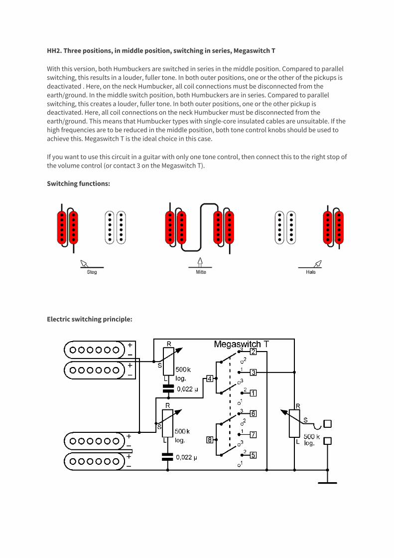
HH2. Three positions, in middle position, switching in series, Megaswitch T
With this version, both Humbuckers are switched in series in the middle position. Compared to parallel switching, this results in a louder, fuller tone. In both outer positions, one or the other of the pickups is deactivated . Here, on the neck Humbucker, all coil connections must be disconnected from the earth/ground. In the middle switch position, both Humbuckers are in series. Compared to parallel switching, this creates a louder, fuller tone. In both outer positions, one or the other pickup is deactivated. Here, all coil connections on the neck Humbucker must be disconnected from the earth/ground. This means that Humbucker types with single-core insulated cables are unsuitable. If the high frequencies are to be reduced in the middle position, both tone control knobs should be used to achieve this. Megaswitch T is the ideal choice in this case.
If you want to use this circuit in a guitar with only one tone control, then connect this to the right stop of the volume control (or contact 3 on the Megaswitch T).
Switching functions:
Electric switching principle:
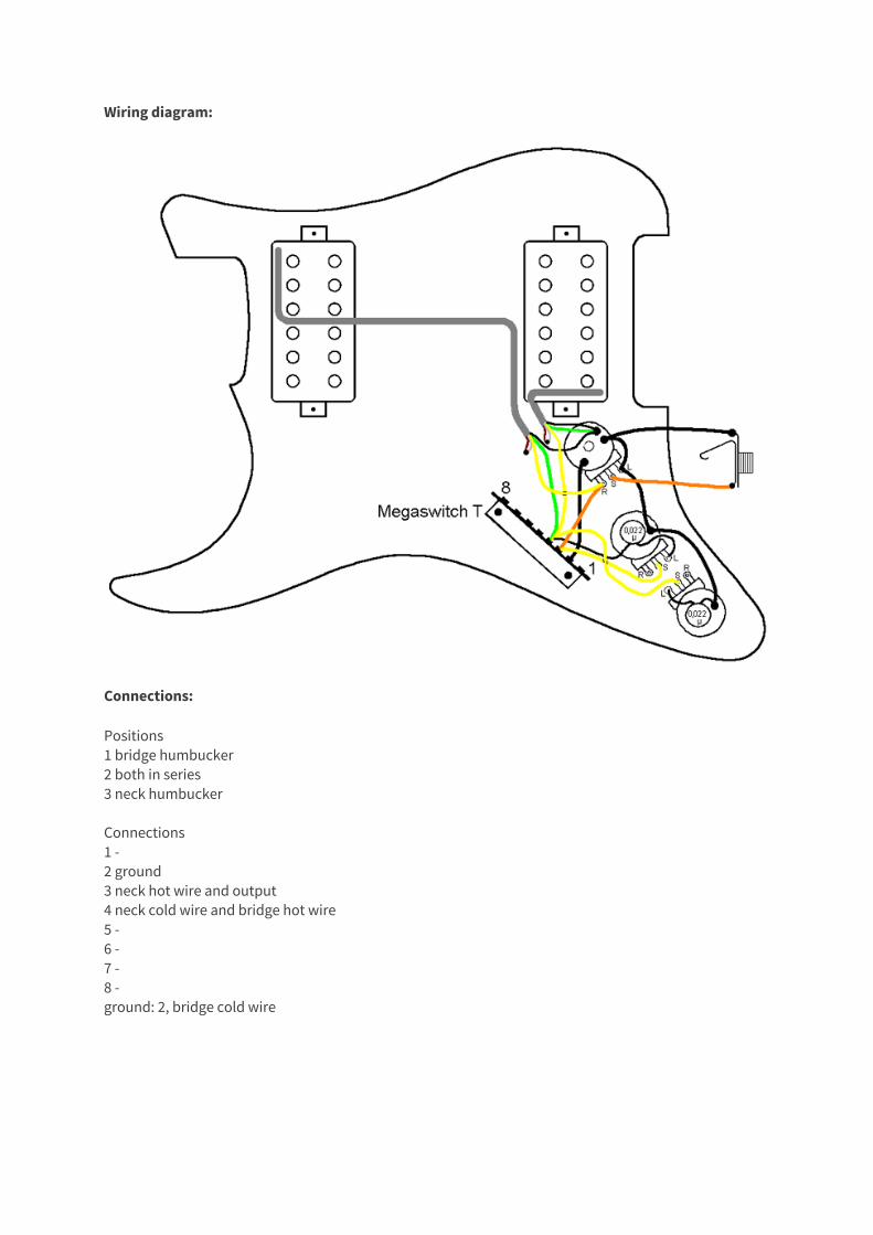
Wiring diagram:
Connections:
Positions 1 bridge humbucker 2 both in series 3 neck humbucker Connections 1 - 2 ground 3 neck hot wire and output 4 neck cold wire and bridge hot wire 5 - 6 - 7 - 8 - ground: 2, bridge cold wire
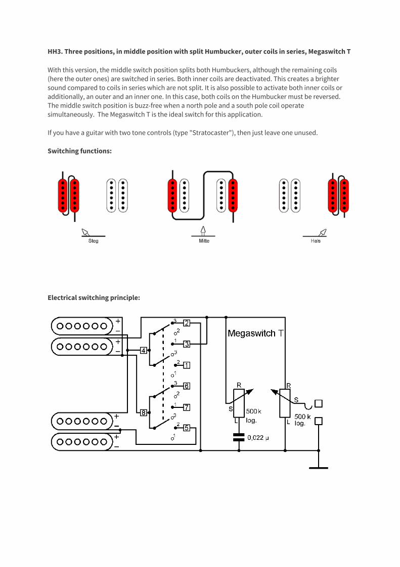
HH3. Three positions, in middle position with split Humbucker, outer coils in series, Megaswitch T
With this version, the middle switch position splits both Humbuckers, although the remaining coils (here the outer ones) are switched in series. Both inner coils are deactivated. This creates a brighter sound compared to coils in series which are not split. It is also possible to activate both inner coils or additionally, an outer and an inner one. In this case, both coils on the Humbucker must be reversed. The middle switch position is buzz-free when a north pole and a south pole coil operate simultaneously. The Megaswitch T is the ideal switch for this application.
If you have a guitar with two tone controls (type "Stratocaster"), then just leave one unused.
Switching functions:
Electrical switching principle:
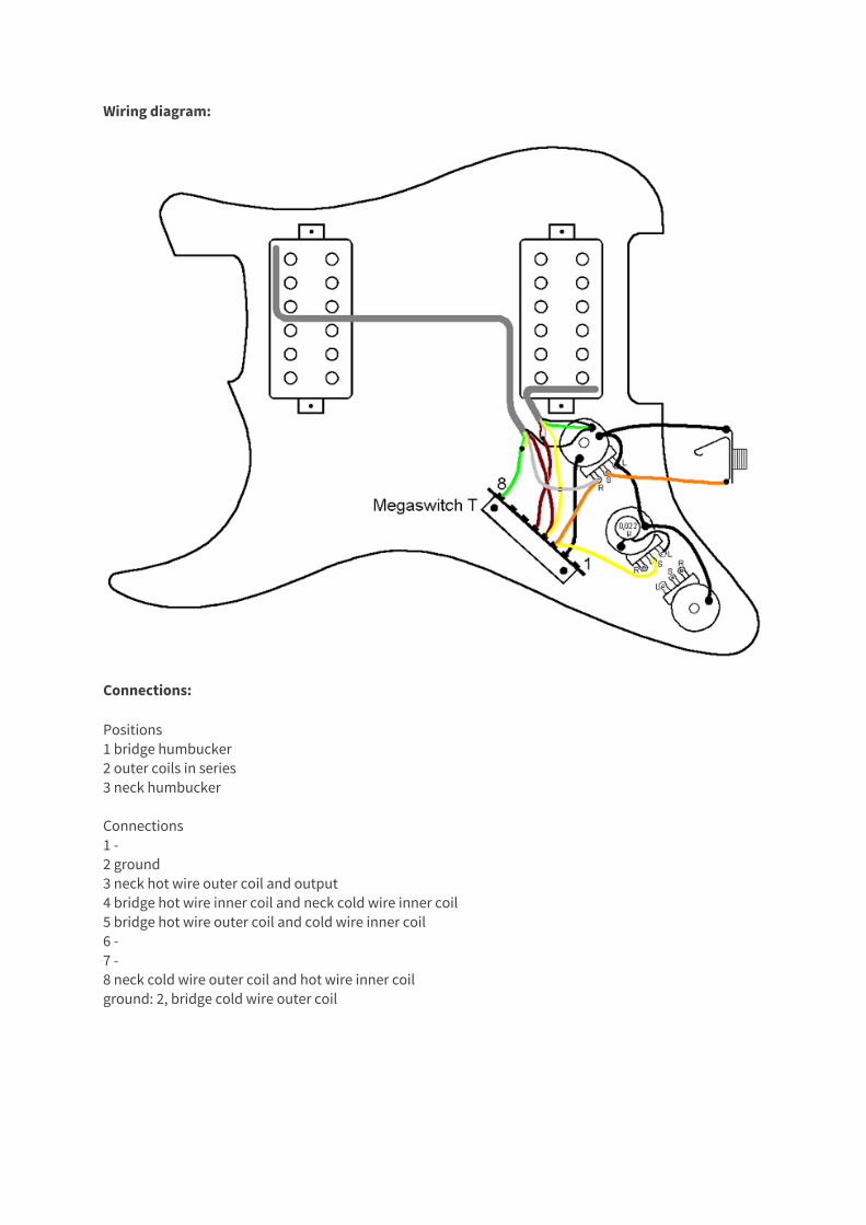
Wiring diagram:
Connections:
Positions 1 bridge humbucker 2 outer coils in series 3 neck humbucker Connections 1 - 2 ground 3 neck hot wire outer coil and output 4 bridge hot wire inner coil and neck cold wire inner coil 5 bridge hot wire outer coil and cold wire inner coil 6 - 7 - 8 neck cold wire outer coil and hot wire inner coil ground: 2, bridge cold wire outer coil
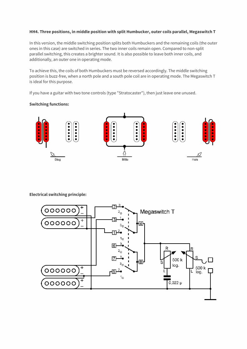
HH4. Three positions, in middle position with split Humbucker, outer coils parallel, Megaswitch T
In this version, the middle switching position splits both Humbuckers and the remaining coils (the outer ones in this case) are switched in series. The two inner coils remain open. Compared to non-split parallel switching, this creates a brighter sound. It is also possible to leave both inner coils, and additionally, an outer one in operating mode.
To achieve this, the coils of both Humbuckers must be reversed accordingly. The middle switching position is buzz-free, when a north pole and a south pole coil are in operating mode. The Megaswitch T is ideal for this purpose.
If you have a guitar with two tone controls (type "Stratocaster"), then just leave one unused.
Switching functions:
Electrical switching principle:
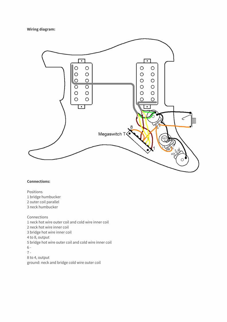
Wiring diagram:
Connections:
Positions 1 bridge humbucker 2 outer coil parallel 3 neck humbucker Connections 1 neck hot wire outer coil and cold wire inner coil 2 neck hot wire inner coil 3 bridge hot wire inner coil 4 to 8, output 5 bridge hot wire outer coil and cold wire inner coil 6 - 7 - 8 to 4, output ground: neck and bridge cold wire outer coil
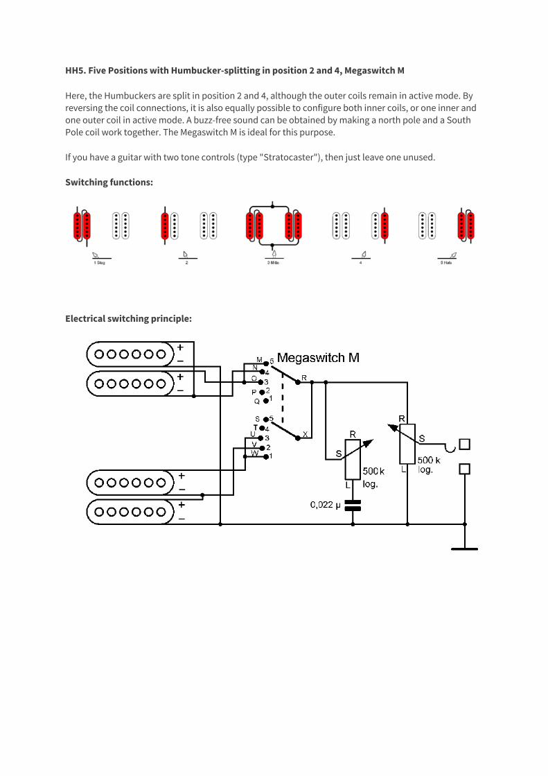
HH5. Five Positions with Humbucker-splitting in position 2 and 4, Megaswitch M
Here, the Humbuckers are split in position 2 and 4, although the outer coils remain in active mode. By reversing the coil connections, it is also equally possible to configure both inner coils, or one inner and one outer coil in active mode. A buzz-free sound can be obtained by making a north pole and a South Pole coil work together. The Megaswitch M is ideal for this purpose.
If you have a guitar with two tone controls (type "Stratocaster"), then just leave one unused.
Switching functions:
Electrical switching principle:
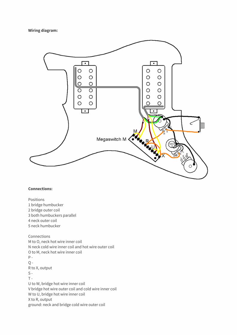
Wiring diagram:
Connections:
Positions 1 bridge humbucker 2 bridge outer coil 3 both humbuckers parallel 4 neck outer coil 5 neck humbucker Connections M to O, neck hot wire inner coil N neck cold wire inner coil and hot wire outer coil O to M, neck hot wire inner coil P - Q - R to X, output S - T - U to W, bridge hot wire inner coil V bridge hot wire outer coil and cold wire inner coil W to U, bridge hot wire inner coil X to R, output ground: neck and bridge cold wire outer coil
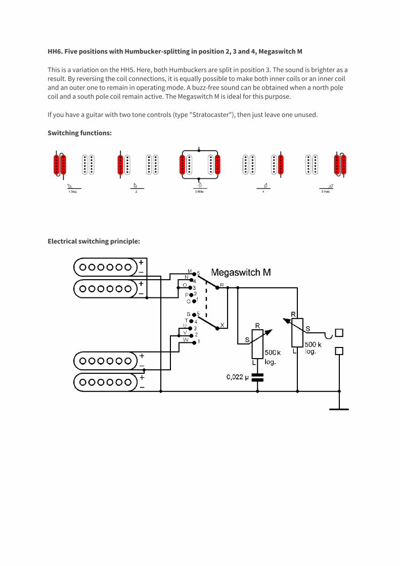
HH6. Five positions with Humbucker-splitting in position 2, 3 and 4, Megaswitch M
This is a variation on the HH5. Here, both Humbuckers are split in position 3. The sound is brighter as a result. By reversing the coil connections, it is equally possible to make both inner coils or an inner coil and an outer one to remain in operating mode. A buzz-free sound can be obtained when a north pole coil and a south pole coil remain active. The Megaswitch M is ideal for this purpose.
If you have a guitar with two tone controls (type "Stratocaster"), then just leave one unused.
Switching functions:
Electrical switching principle:
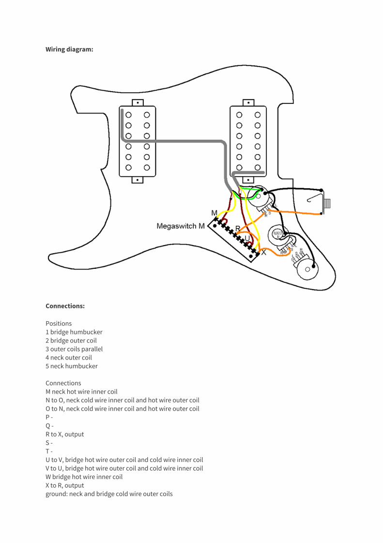
Wiring diagram:
Connections:
Positions 1 bridge humbucker 2 bridge outer coil 3 outer coils parallel 4 neck outer coil 5 neck humbucker Connections M neck hot wire inner coil N to O, neck cold wire inner coil and hot wire outer coil O to N, neck cold wire inner coil and hot wire outer coil P - Q - R to X, output S - T - U to V, bridge hot wire outer coil and cold wire inner coil V to U, bridge hot wire outer coil and cold wire inner coil W bridge hot wire inner coil X to R, output ground: neck and bridge cold wire outer coils
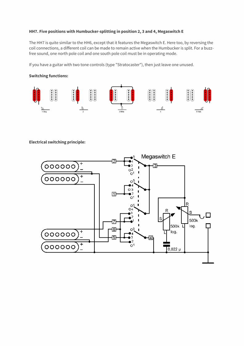
HH7. Five positions with Humbucker-splitting in position 2, 3 and 4, Megaswitch E
The HH7 is quite similar to the HH6, except that it features the Megaswitch E. Here too, by reversing the coil connections, a different coil can be made to remain active when the Humbucker is split. For a buzz-free sound, one north pole coil and one south pole coil must be in operating mode.
If you have a guitar with two tone controls (type "Stratocaster"), then just leave one unused.
Switching functions:
Electrical switching principle:
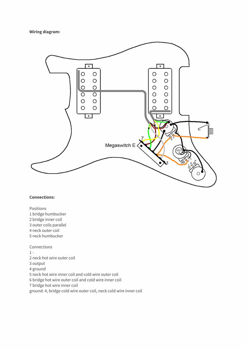
Wiring diagram:
Connections:
Positions 1 bridge humbucker 2 bridge inner coil 3 outer coils parallel 4 neck outer coil 5 neck humbucker Connections 1 - 2 neck hot wire outer coil 3 output 4 ground 5 neck hot wire inner coil and cold wire outer coil 6 bridge hot wire outer coil and cold wire inner coil 7 bridge hot wire inner coil ground: 4, bridge cold wire outer coil, neck cold wire inner coil
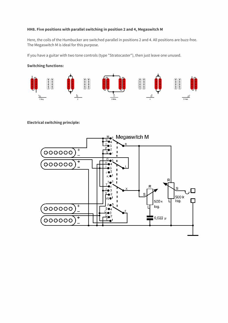
HH8. Five positions with parallel switching in position 2 and 4, Megaswitch M
Here, the coils of the Humbucker are switched parallel in positions 2 and 4. All positions are buzz-free. The Megaswitch M is ideal for this purpose.
If you have a guitar with two tone controls (type "Stratocaster"), then just leave one unused.
Switching functions:
Electrical switching principle:
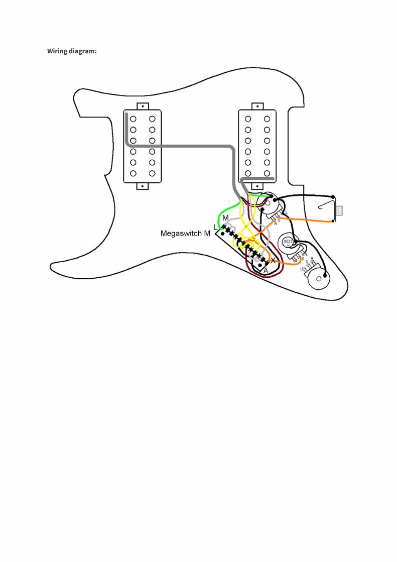
Wiring diagram:

Connections:
Positions 1 bridge humbucker in series 2 bridge humbucker parallel 3 both humbuckers (each in series) parallel 4 neck humbucker parallel 5 neck humbucker in series Connections A - B - C to E and V, bridge hot wire outer coil D to H and ground E to C and V, bridge hot wire outer coil F bridge cold wire inner coil G to I and T, neck hot wire inner coil H to D and ground I to G and T, neck hot wire inner coil J - K - L neck cold wire outer coil M to N and O, neck hot wire outer coil N to M and O neck hot wire outer coil O to N and M, neck hot wire outer coil P to Q and U, bridge hot wire inner coil Q to P and U, bridge hot wire inner coil R to X and output S - T to G and I, neck hot wire inner coil U to P and Q, bridge hot wire inner coil V to C and E, bridge hot wire outer coil W - X to R and output ground: D, H, neck cold wire inner coil, bridge cold wire outer coil
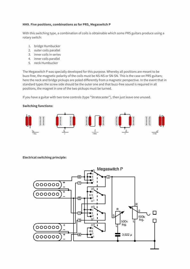
HH9. Five positions, combinations as for PRS, Megaswitch P
With this switching type, a combination of coils is obtainable which some PRS guitars produce using a rotary switch:
1. bridge Humbucker 2. outer coils parallel 3. inner coils in series 4. inner coils parallel 5. neck Humbucker
The Megaswitch P was specially developed for this purpose. Whereby all positions are meant to be buzz-free, the magnetic polarity of the coils must be NS-NS or SN-SN. This is the case on PRS guitars; here the neck and bridge pickups are poled differently from a magnetic perspective. In the event that in standard types the screw side should be the outer one and that buzz-free sound is required in all positions, the magnet in one of the two pickups must be turned.
If you have a guitar with two tone controls (type "Stratocaster"), then just leave one unused.
Switching functions:
Electrical switching principle:
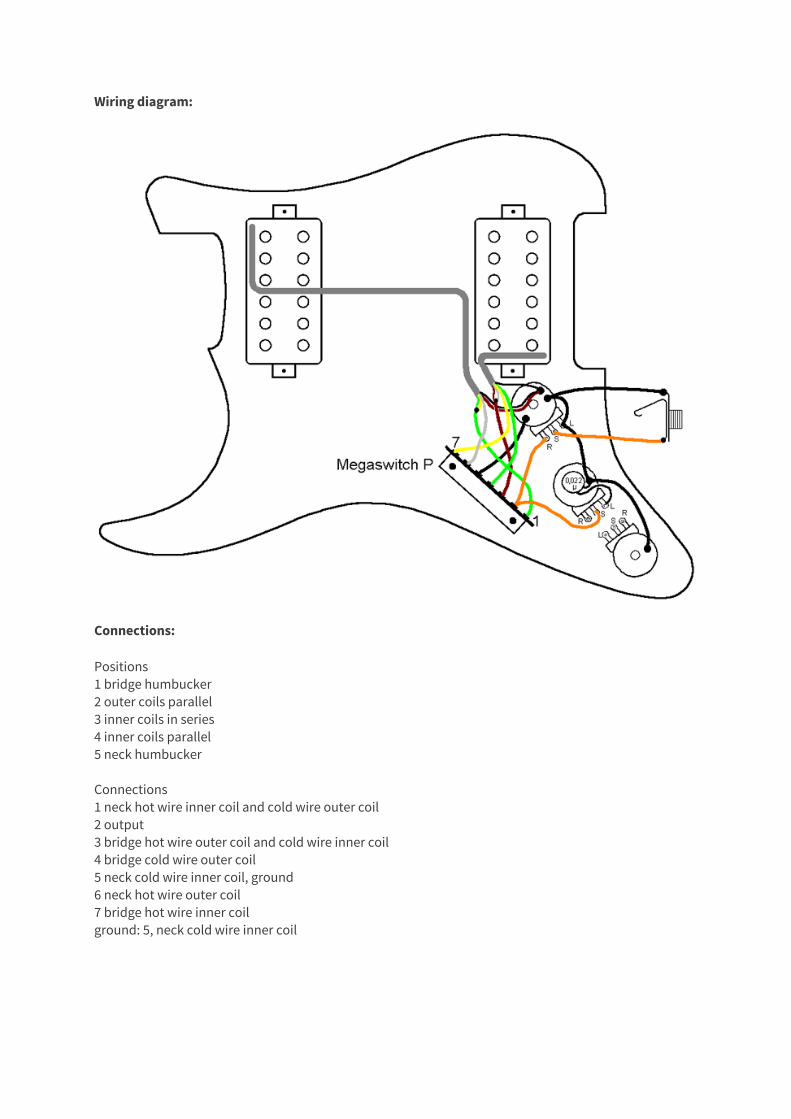
Wiring diagram:
Connections:
Positions 1 bridge humbucker 2 outer coils parallel 3 inner coils in series 4 inner coils parallel 5 neck humbucker Connections 1 neck hot wire inner coil and cold wire outer coil 2 output 3 bridge hot wire outer coil and cold wire inner coil 4 bridge cold wire outer coil 5 neck cold wire inner coil, ground 6 neck hot wire outer coil 7 bridge hot wire inner coil ground: 5, neck cold wire inner coil
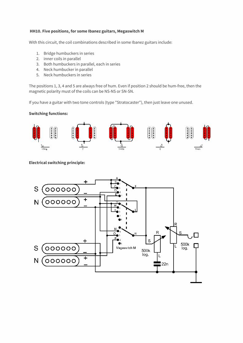
HH10. Five positions, for some Ibanez guitars, Megaswitch M
With this circuit, the coil combinations described in some Ibanez guitars include:
1. Bridge humbuckers in series 2. inner coils in parallel 3. Both humbuckers in parallel, each in series 4. Neck humbucker in parallel 5. Neck humbuckers in series
The positions 1, 3, 4 and 5 are always free of hum. Even if position 2 should be hum-free, then the magnetic polarity must of the coils can be NS-NS or SN-SN.
If you have a guitar with two tone controls (type "Stratocaster"), then just leave one unused.
Switching functions:
Electrical switching principle:
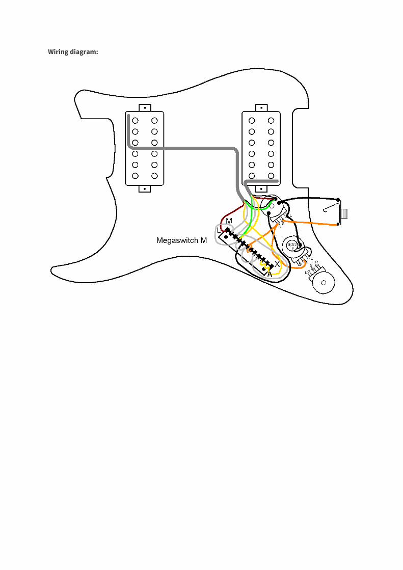
Wiring diagram:
Connections:
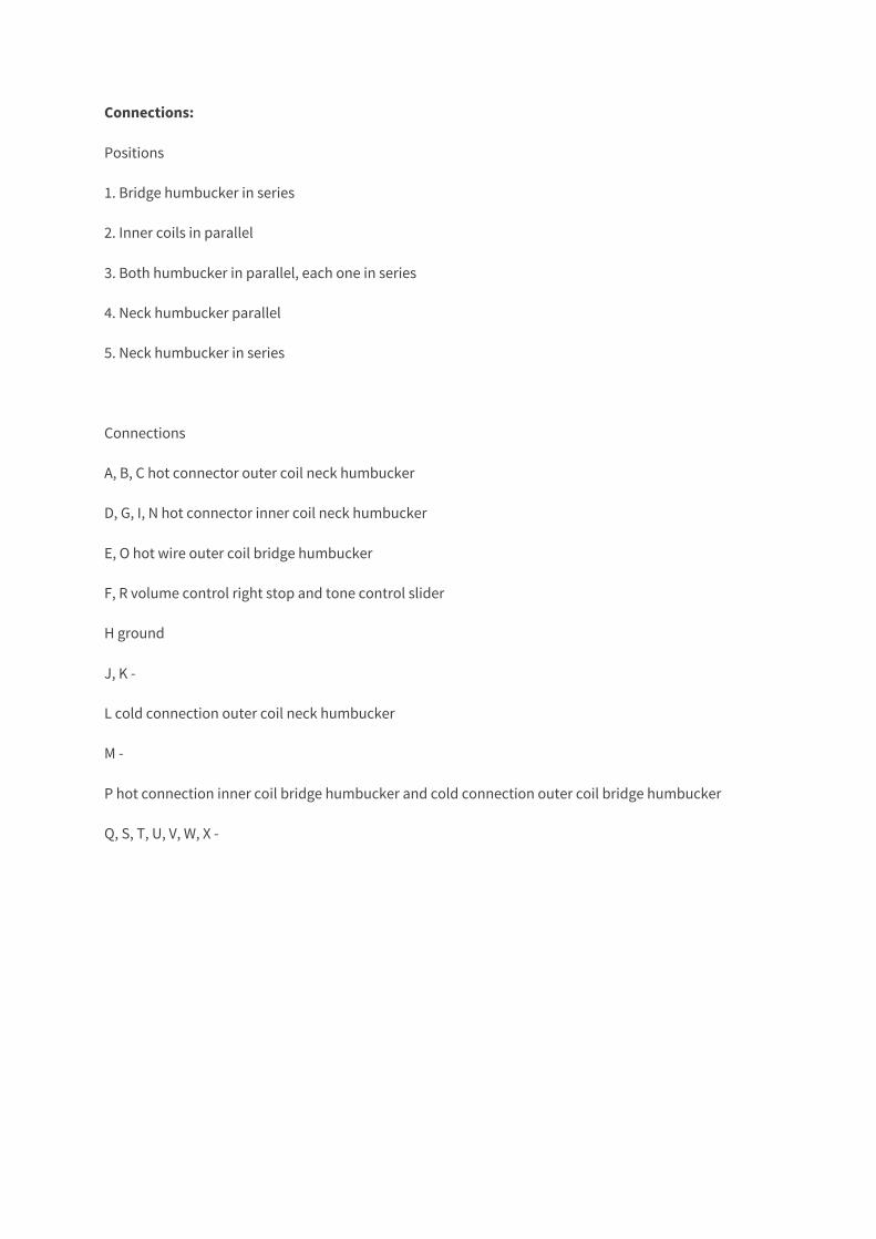
Positions
1. Bridge humbucker in series
2. Inner coils in parallel
3. Both humbucker in parallel, each one in series
4. Neck humbucker parallel
5. Neck humbucker in series
Connections
A, B, C hot connector outer coil neck humbucker
D, G, I, N hot connector inner coil neck humbucker
E, O hot wire outer coil bridge humbucker
F, R volume control right stop and tone control slider
H ground
J, K -
L cold connection outer coil neck humbucker
M -
P hot connection inner coil bridge humbucker and cold connection outer coil bridge humbucker
Q, S, T, U, V, W, X -
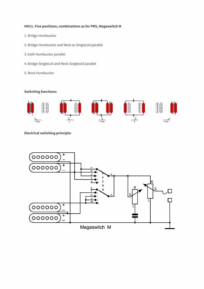
HH11. Five positions, combinations as for PRS, Megaswitch M
1. Bridge-Humbucker
2. Bridge-Humbucker and Neck as Singlecoil parallel
3. both Humbucker parallel
4. Bridge-Singlecoil and Neck-Singlecoil parallel
5. Neck-Humbucker
Switching functions:
Electrical switching principle:
Wiring diagram:
Connections:
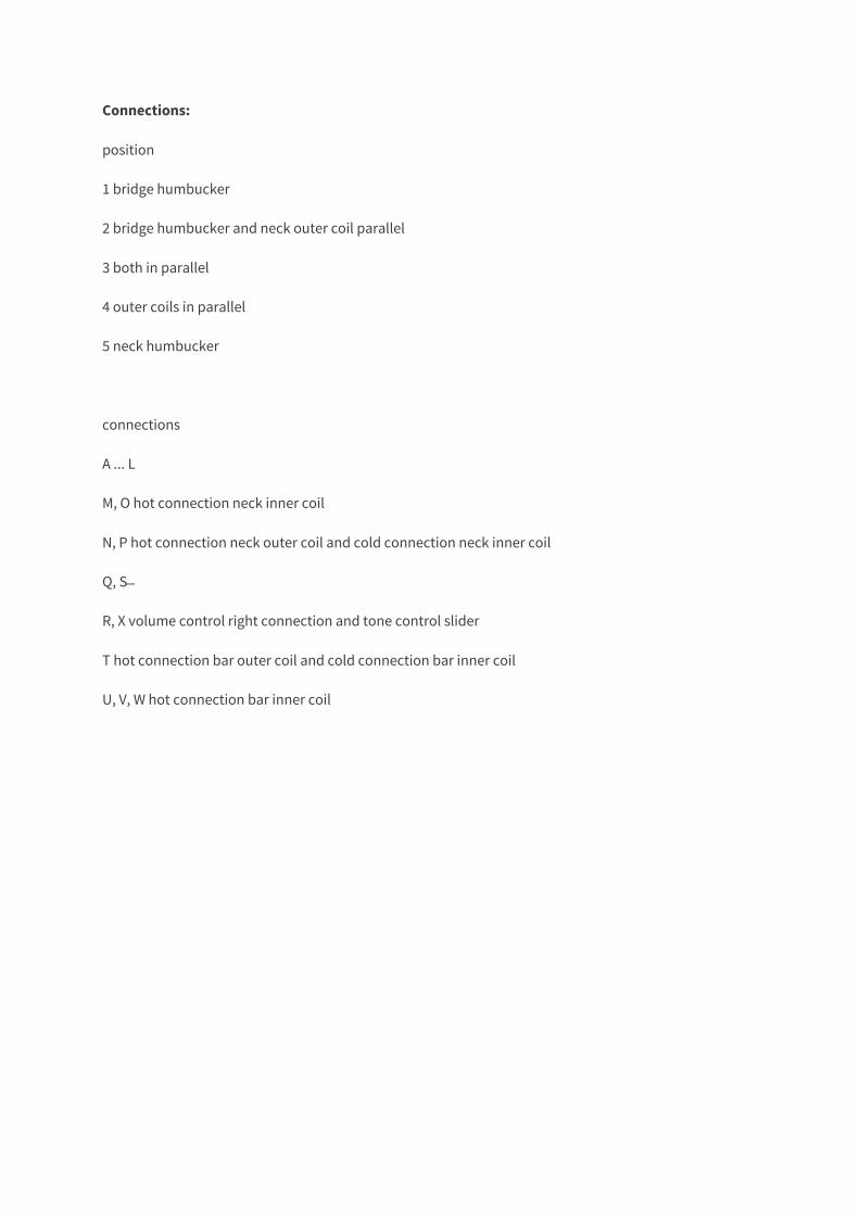
position
1 bridge humbucker
2 bridge humbucker and neck outer coil parallel
3 both in parallel
4 outer coils in parallel
5 neck humbucker
connections
A ... L
M, O hot connection neck inner coil
N, P hot connection neck outer coil and cold connection neck inner coil
Q, S ̶
R, X volume control right connection and tone control slider
T hot connection bar outer coil and cold connection bar inner coil
U, V, W hot connection bar inner coil
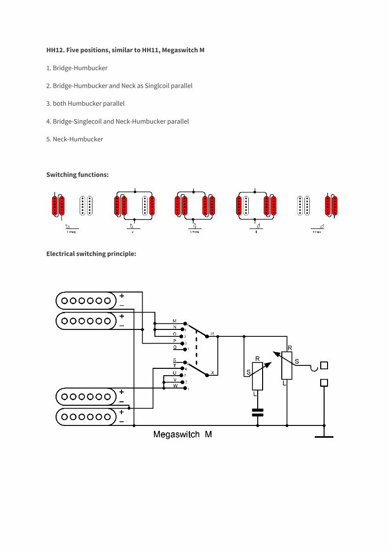
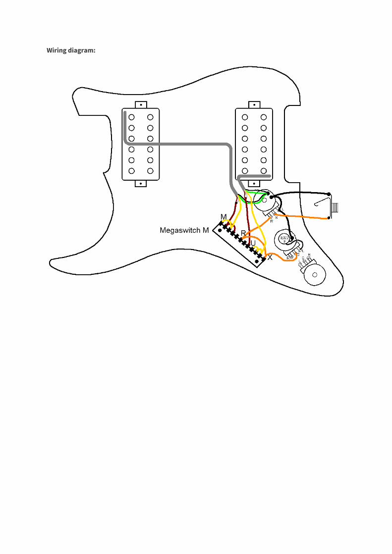
HH12. Five positions, similar to HH11, Megaswitch M
1. Bridge-Humbucker
2. Bridge-Humbucker and Neck as Singlcoil parallel
3. both Humbucker parallel
4. Bridge-Singlecoil and Neck-Humbucker parallel
5. Neck-Humbucker
Switching functions:
Electrical switching principle:
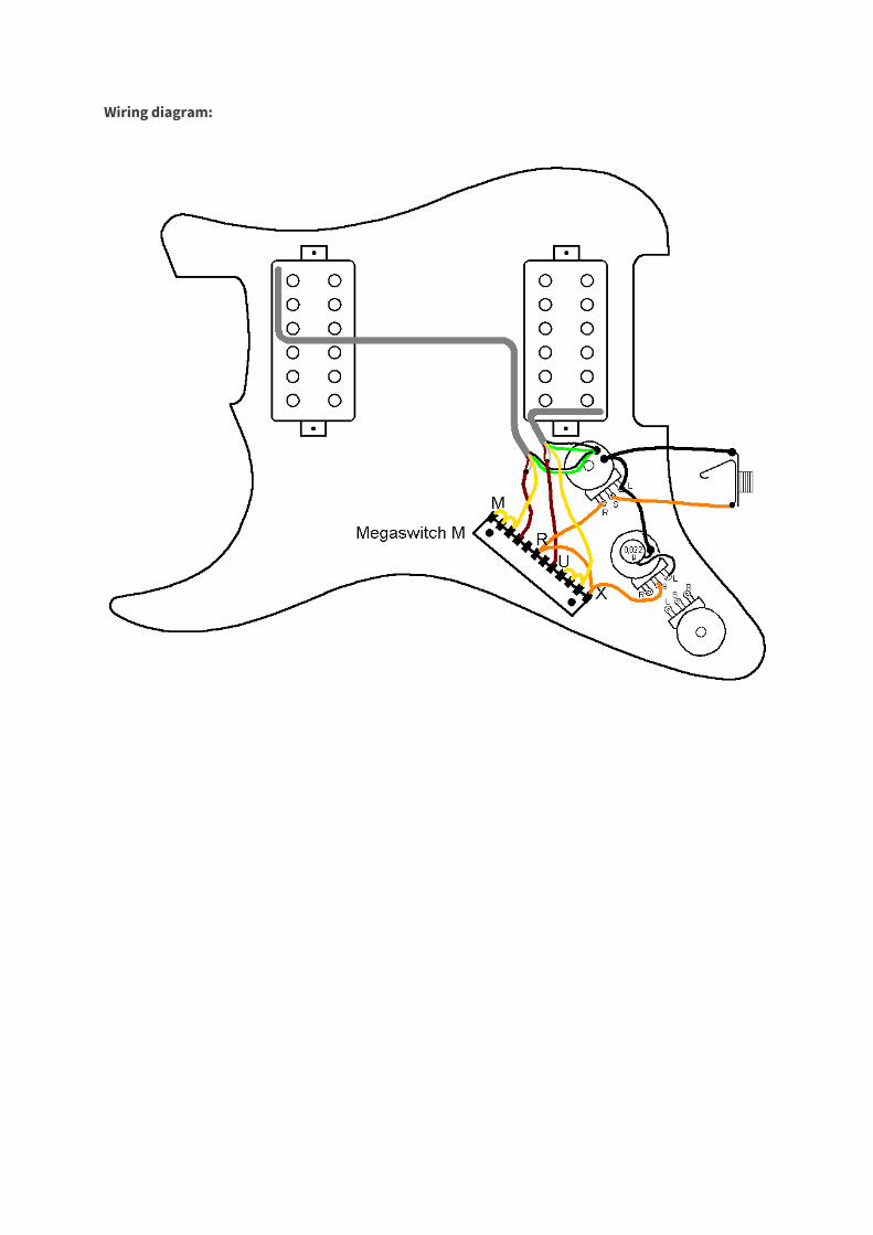
Wiring diagram:
Connections:
position
1 bridge humbucker
2 bridge humbucker and neck outer coil parallel
3 both in parallel
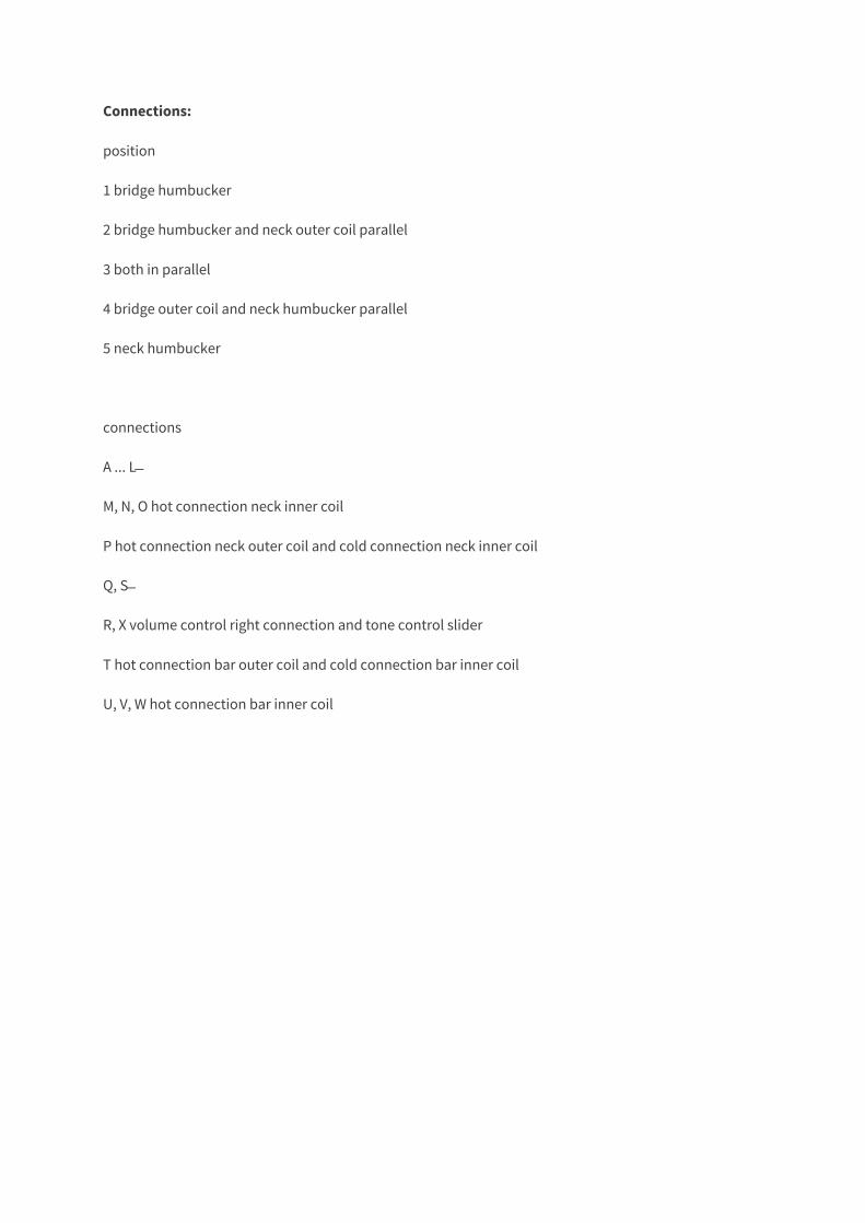
4 bridge outer coil and neck humbucker parallel
5 neck humbucker
connections
A ... L ̶
M, N, O hot connection neck inner coil
P hot connection neck outer coil and cold connection neck inner coil
Q, S ̶
R, X volume control right connection and tone control slider
T hot connection bar outer coil and cold connection bar inner coil
U, V, W hot connection bar inner coil


![B C&% % 1 % 8 : G ':&% I G J & D %7L% . 3 · [ $3 hh hh$#hh 1 [hhh hh hh dhhphh #hhm#hhbhh hh&lhh < w) d?. {lhh hh$ @b#-p 3 c 3:;hhh $# #" )j p d] #hhm#hhbhh hh&x %hh | x4 3 hh?hh](https://img.pdfslide.net/doc/110x75/5ea61d5cbec94348cc54f9a5/b-c-1-8-g-i-g-j-d-7l-3-3-hh-hhhh-1-hhh-hh-hh.jpg)


![HH.1 Historic Heritage - Whangarei€¦ · HH.1 Historic Heritage 14 September 2016 [3] Trim 16/102400 Note: Chapter HH (Historic Heritage) is designed to serve as a framework/overview](https://img.pdfslide.net/doc/110x75/5f09442f7e708231d4260047/hh1-historic-heritage-hh1-historic-heritage-14-september-2016-3-trim-16102400.jpg)