Embed Size (px)
Citation preview
University of Texas at Austin CS384G - Computer Graphics Fall 2010 Don Fussell
Hierarchical Modeling
University of Texas at Austin CS384G - Computer Graphics Fall 2010 Don Fussell 2
Reading
Angel, sections 9.1 - 9.6[reader pp. 169-185]OpenGL Programming Guide, chapter 3
Focus especially on section titled“Modelling Transformations”.
University of Texas at Austin CS384G - Computer Graphics Fall 2010 Don Fussell 3
Hierarchical Modeling
Consider a moving automobile, with 4wheels attached to the chassis, and lug nutsattached to each wheel:
University of Texas at Austin CS384G - Computer Graphics Fall 2010 Don Fussell 4
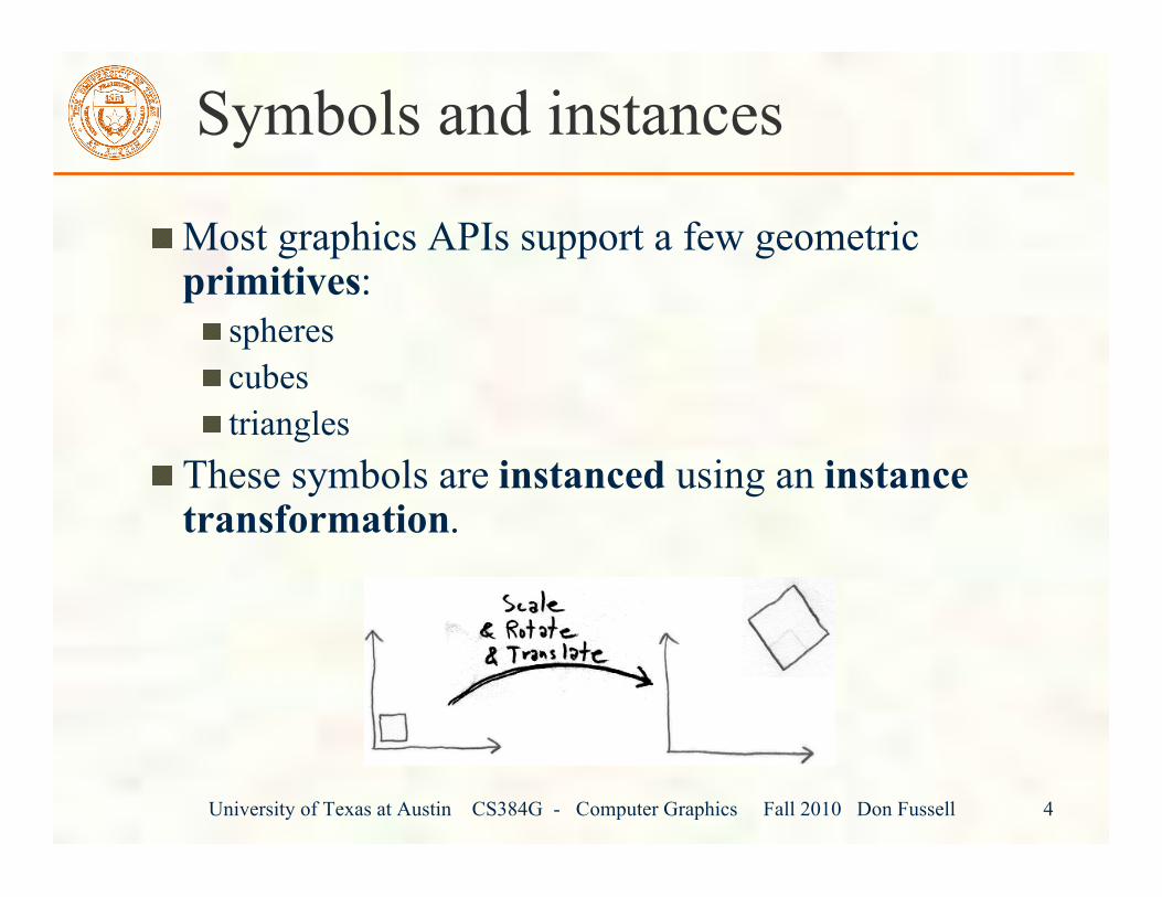
Symbols and instances
Most graphics APIs support a few geometricprimitives:
spherescubestriangles
These symbols are instanced using an instancetransformation.
University of Texas at Austin CS384G - Computer Graphics Fall 2010 Don Fussell 5
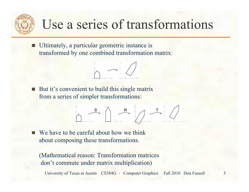
Use a series of transformationsUltimately, a particular geometric instance istransformed by one combined transformation matrix:
But it’s convenient to build this single matrixfrom a series of simpler transformations:
We have to be careful about how we thinkabout composing these transformations.
(Mathematical reason: Transformation matrices don’t commute under matrix multiplication)
University of Texas at Austin CS384G - Computer Graphics Fall 2010 Don Fussell 6
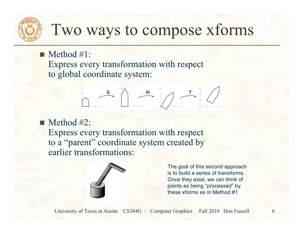
Two ways to compose xformsMethod #1:Express every transformation with respectto global coordinate system:
Method #2:Express every transformation with respectto a “parent” coordinate system created byearlier transformations:
The goal of this second approachis to build a series of transforms.Once they exist, we can think ofpoints as being “processed” bythese xforms as in Method #1
University of Texas at Austin CS384G - Computer Graphics Fall 2010 Don Fussell 7
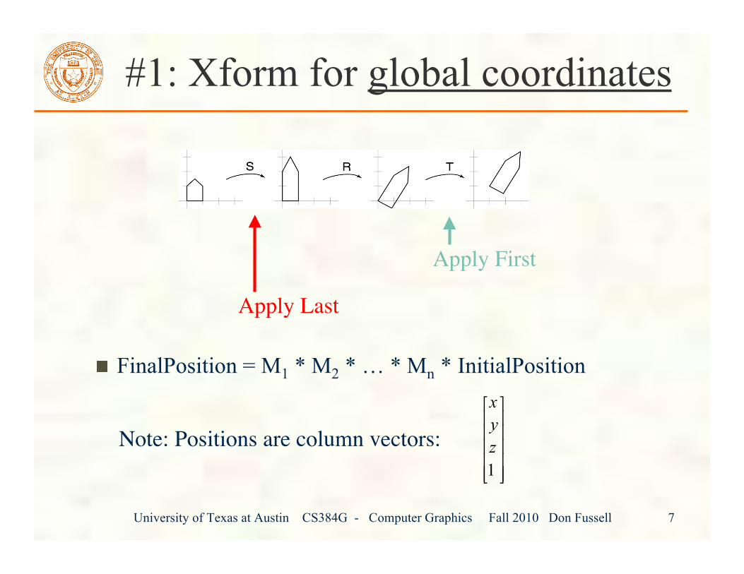
#1: Xform for global coordinates
FinalPosition = M1 * M2 * … * Mn * InitialPosition
Apply First
Apply Last
Note: Positions are column vectors: 1
x
y
z
! "# $# $# $# $# $% &
University of Texas at Austin CS384G - Computer Graphics Fall 2010 Don Fussell 8
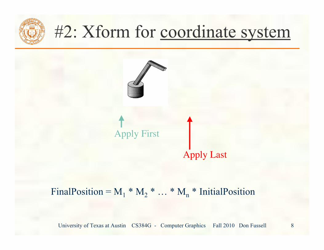
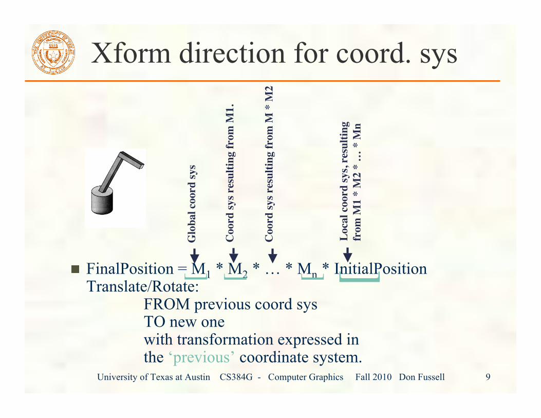
#2: Xform for coordinate system
FinalPosition = M1 * M2 * … * Mn * InitialPosition
Apply First
Apply Last
University of Texas at Austin CS384G - Computer Graphics Fall 2010 Don Fussell 9
Xform direction for coord. sys
FinalPosition = M1 * M2 * … * Mn * InitialPositionTranslate/Rotate: FROM previous coord sys TO new one with transformation expressed in the ‘previous’ coordinate system.
Glo
bal c
oord
sys
Coo
rd sy
s res
ultin
g fr
om M
1.
Loca
l coo
rd sy
s, re
sulti
ngfr
om M
1 *
M2
* …
* M
n
[[ [ [
Coo
rd sy
s res
ultin
g fr
om M
* M
2
University of Texas at Austin CS384G - Computer Graphics Fall 2010 Don Fussell 10
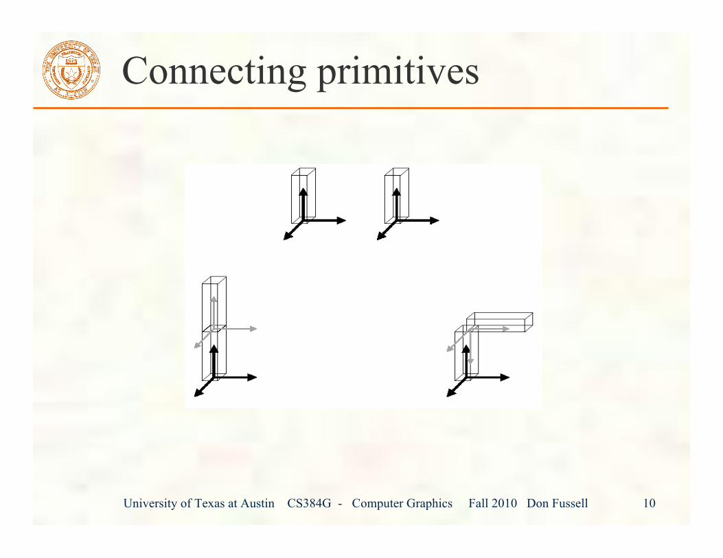
Connecting primitives
University of Texas at Austin CS384G - Computer Graphics Fall 2010 Don Fussell 11
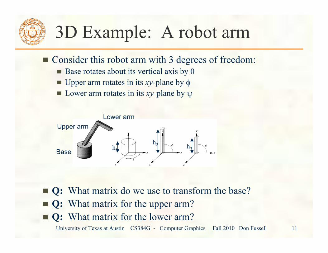
3D Example: A robot armConsider this robot arm with 3 degrees of freedom:
Base rotates about its vertical axis by θUpper arm rotates in its xy-plane by φLower arm rotates in its xy-plane by ψ
Q: What matrix do we use to transform the base?Q: What matrix for the upper arm?Q: What matrix for the lower arm?
h1h2 h3Base
Upper armLower arm
University of Texas at Austin CS384G - Computer Graphics Fall 2010 Don Fussell 12
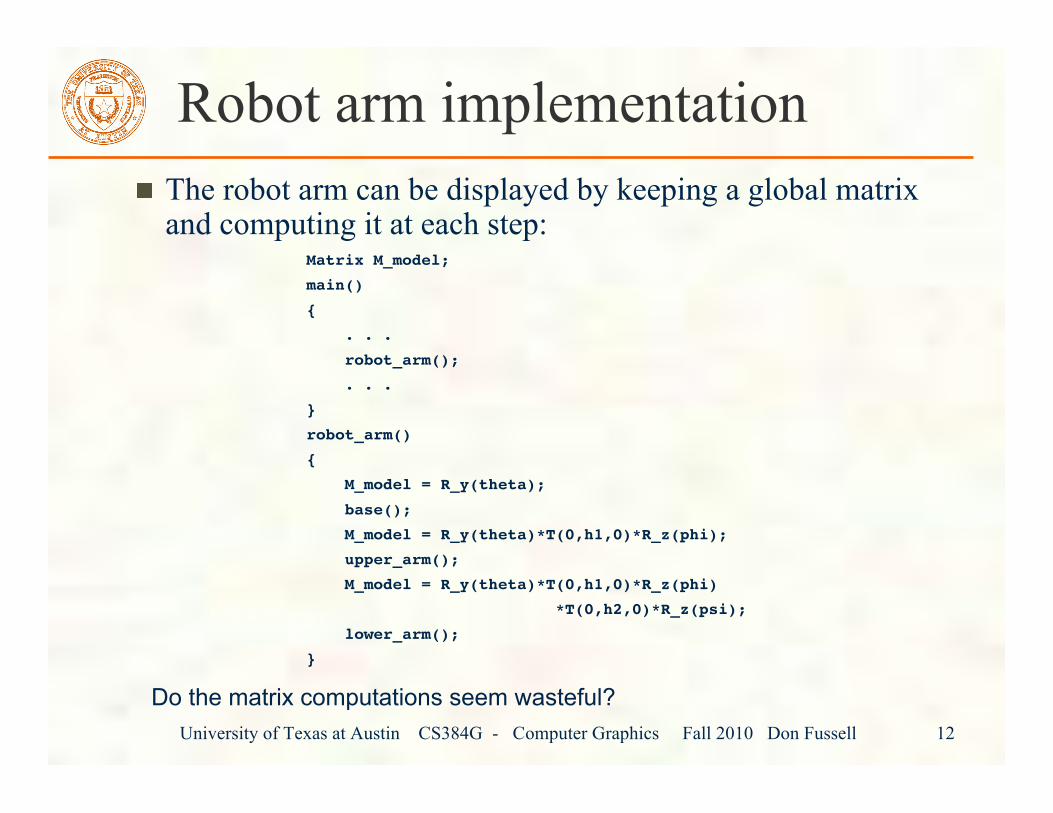
Robot arm implementationThe robot arm can be displayed by keeping a global matrixand computing it at each step:
Matrix M_model;
main()
{
. . .
robot_arm();
. . .
}
robot_arm()
{
M_model = R_y(theta);
base();
M_model = R_y(theta)*T(0,h1,0)*R_z(phi);
upper_arm();
M_model = R_y(theta)*T(0,h1,0)*R_z(phi)
*T(0,h2,0)*R_z(psi);
lower_arm();
}
Do the matrix computations seem wasteful?
University of Texas at Austin CS384G - Computer Graphics Fall 2010 Don Fussell 13
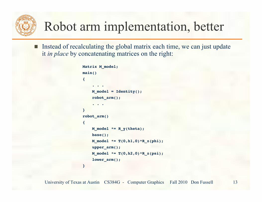
Instead of recalculating the global matrix each time, we can just updateit in place by concatenating matrices on the right:
Matrix M_model;
main()
{
. . .
M_model = Identity();
robot_arm();
. . .
}
robot_arm()
{
M_model *= R_y(theta);
base();
M_model *= T(0,h1,0)*R_z(phi);
upper_arm();
M_model *= T(0,h2,0)*R_z(psi);
lower_arm();
}
Robot arm implementation, better
University of Texas at Austin CS384G - Computer Graphics Fall 2010 Don Fussell 14
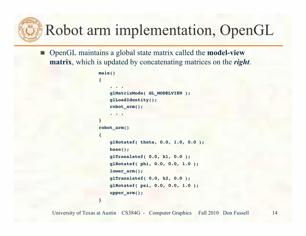
OpenGL maintains a global state matrix called the model-viewmatrix, which is updated by concatenating matrices on the right.
main(){ . . . glMatrixMode( GL_MODELVIEW ); glLoadIdentity(); robot_arm(); . . .
}
robot_arm()
{
glRotatef( theta, 0.0, 1.0, 0.0 );
base();
glTranslatef( 0.0, h1, 0.0 );
glRotatef( phi, 0.0, 0.0, 1.0 );
lower_arm();
glTranslatef( 0.0, h2, 0.0 );
glRotatef( psi, 0.0, 0.0, 1.0 );
upper_arm();
}
Robot arm implementation, OpenGL
University of Texas at Austin CS384G - Computer Graphics Fall 2010 Don Fussell 15
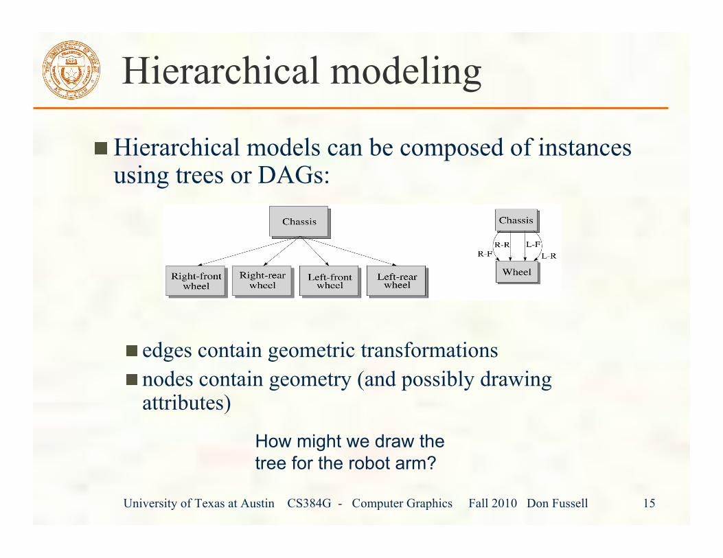
Hierarchical modeling
Hierarchical models can be composed of instancesusing trees or DAGs:
edges contain geometric transformationsnodes contain geometry (and possibly drawingattributes)
How might we draw thetree for the robot arm?
University of Texas at Austin CS384G - Computer Graphics Fall 2010 Don Fussell 16
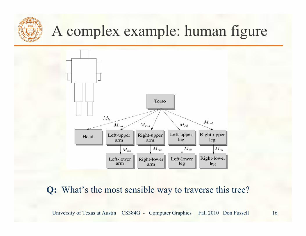
A complex example: human figure
Q: What’s the most sensible way to traverse this tree?
University of Texas at Austin CS384G - Computer Graphics Fall 2010 Don Fussell 17
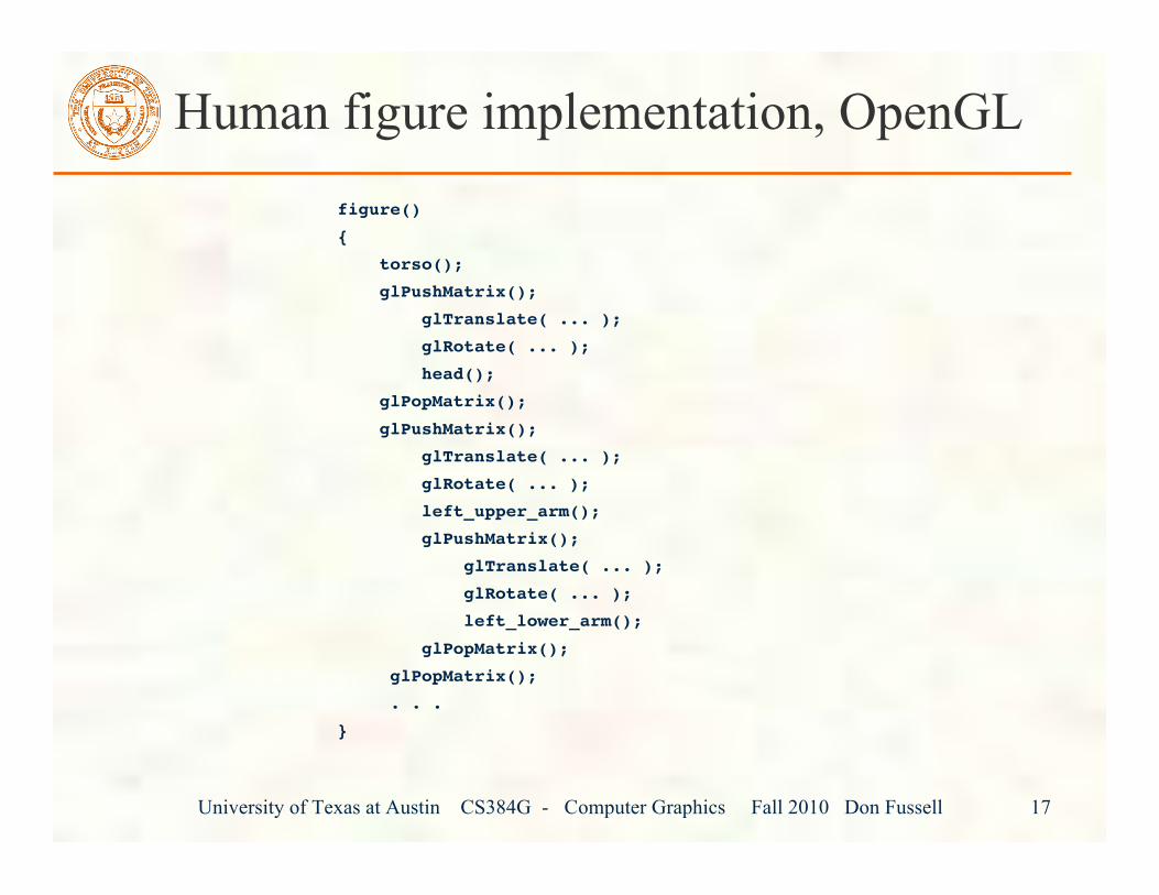
Human figure implementation, OpenGLfigure()
{
torso();
glPushMatrix();
glTranslate( ... );
glRotate( ... );
head();
glPopMatrix();
glPushMatrix();
glTranslate( ... );
glRotate( ... );
left_upper_arm();
glPushMatrix();
glTranslate( ... );
glRotate( ... );
left_lower_arm();
glPopMatrix();
glPopMatrix();
. . .
}
University of Texas at Austin CS384G - Computer Graphics Fall 2010 Don Fussell 18
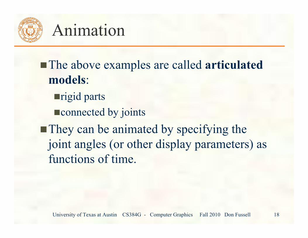
Animation
The above examples are called articulatedmodels:
rigid partsconnected by joints
They can be animated by specifying thejoint angles (or other display parameters) asfunctions of time.
University of Texas at Austin CS384G - Computer Graphics Fall 2010 Don Fussell 19
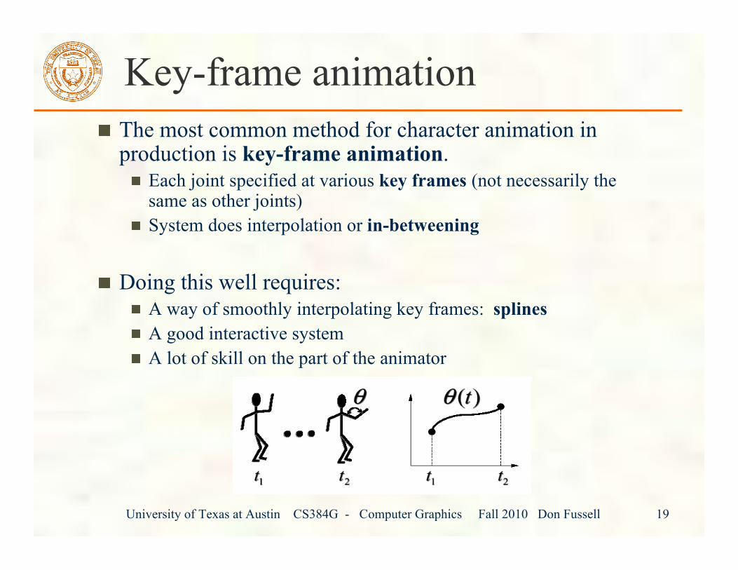
Key-frame animationThe most common method for character animation inproduction is key-frame animation.
Each joint specified at various key frames (not necessarily thesame as other joints)System does interpolation or in-betweening
Doing this well requires:A way of smoothly interpolating key frames: splinesA good interactive systemA lot of skill on the part of the animator
University of Texas at Austin CS384G - Computer Graphics Fall 2010 Don Fussell 20
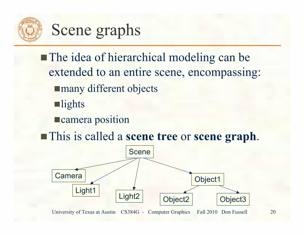
Scene graphsThe idea of hierarchical modeling can beextended to an entire scene, encompassing:
many different objectslightscamera position
This is called a scene tree or scene graph.
Camera
Light1Light2 Object2 Object3
Scene
Object1