Embed Size (px)
Citation preview
1,POR- NO. NADC-8155-30
tp
HIGH ALTITUDE LAUNCHOF
ASW SONOBUOYS
Roger A. HollerSensors and Avionics Technology Directorate
NAVAL AIR DEVELOPMENT CENTERWarminster, Pennsylvania 18974 S EL C
ELECTENOV 3 98e1
JUNE 198
BFINAL REPORT
AIRTASK NO. A035-370A/001 B/OF1 1 -100-000Work Unit No. ZU701
APPROVED FOR PUBLIC RELEASE; DISTPIBUTION UNLIMITED
0
IL.J Prepared forNAVAL AIR SYSTEMS COMMAND
Department of the NavyM Washington, D. C. 20361
81 11 03 00$t-,
NOTICES
REPORT NUMBERING. SYSTEM - The numbering of technical project reports issued by the
Naval Air Development Center is arranged for specific identification purposes. Each
number consists of the Center acronym, the calendar year in which the number was
assigned, the sequence number of the report within the specific calendar year, and
the official 2-digit correspondence code of the Command Office or the Functional
Directorate responsible for the report. For example: Report No. NADC-78015-20
indicates the fifteenth Center report for the year 1978, and prepared by the SystemsDirectorate. The numerical codes are as follows:
CODE OFFICE OR DIRECTORATE
00 Commander, Naval Air Development Center01 Technical Director, Naval Air Development Center02 Comptroller10 Directorate Command Projects20 Systems Directorate30 Sens3rs 4 Avionics Technology Directorate40 Commumication 6 Navigation Technology Directorateso Software Computer Directorate60 Aircraft & Crew Systems Technology Directorate70 Planning Assessment Resources80 Engineering Support Group
PRODUCT ENDORSEMENT - The discussion or instructions concerning commercial productsherein do not constitute an endorsement by the Government nor do they convey orimply the license or right to use such products.
APPROVED BY: _DATE: ý' ,/ g
VIE UNCLASSIFIEDQeCU.-ITY CLASSIFICATION OF THIS PAGE (When Data Enresrd) .
REPORT DOCUMENTATION PAGE READ INSTRUCTIONSBEFORE COMPLETING FORM
1. RPRT NUMBER ,2. GOVT ACCESSION NO. 3. RECIPIENT'S CATALOG NUMBER
j ADC-81155-3 IS. TYPE OF REPORT & PERIOD COVERED
HIGH ALTITUDE LAUNCH OF ASW SONOBUOYS * Final Ley&taG.I-P6. _Q••lG-ORq-WORT NUMBER
7•. AUTHO~RO ,. CONTRACT Q-LGRAhLT..WJM "I
9. PERFORMING ORoANIZATION NAME AND ADDRESS 10. PROGRAM ELEMENT.,PROJECT. TASKAREA & WORK UNIT NUMBERSSSensors and Avionics Technology Directorate
SNaval Air Development Center AIRTASK A035-370A/001B/0F11-SWarminster, PA 18974 100-000; Work Unit ZU701
[Naval Air Systems CommandDepartment of the NavyWashington, DC 20361 3114. MONITORIN5 AGENCY NAME & ADDRES50f different from Controlling Office) 15. SECURITY CLASS. (of this teport)
S)W :UnclassifiediS5. DECLASSIFICATION/DOWNGRADING
SCHEDULE
IS. DISTRIBUTION STATEMENT (of this Report)
Approved for Public Release; Distribution Unlimited.
17. DISTRIBUTION STATEMENT (of the abstract entered in Block 20. if dilfferet h1m Report)
18. SUPPLEMENTARY NOTES
19. KEY WORDS (Continue an reverse aide if necesemry and idenatil by block numbee)
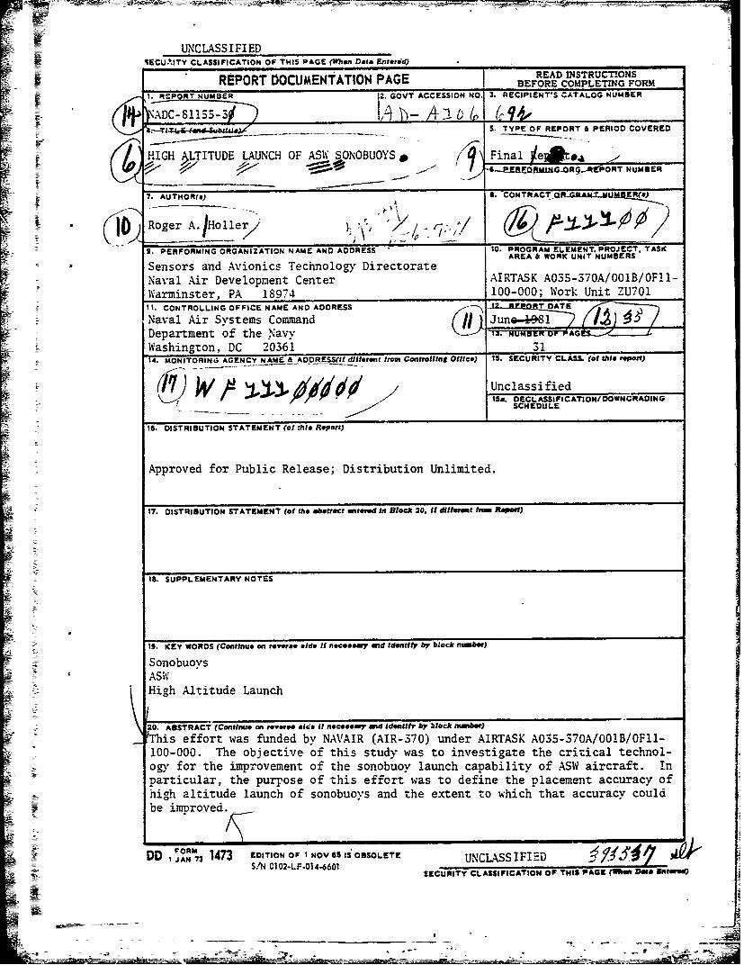
SonobuoysASWHigh Altitude Launch
20. ABSTRACT (Continue an revters aide If necesary and Ld~enttr by block nmber)
JThis effort was funded by NAVAIR (AIR-370) under AIRTASK A03S-370A/001B/OFII-100-000. The objective of this study was to investigate the critical technol-ogy for the improvement of the sonobuoy launch capability of ASW aircraft. inparticular, the purpose of this effort was to define the placement accuracy ofhigh altitude launch of sonobuoys and the extent to which that accuracy couldbe imvroved. _
P o EDITION OF I NOV 65 IS OBSOLETE UNCLASSIFID•..• •DD J AN 73 U1C73S =F-D ..S/N C 02-LF-014-6601 SECURITY CLASSIFICATION OF THIS PAGE (SliM De IMled)
_ _ _ _L*
SECURITY CLASSIFICATI'ON OF THI1S PAGE #Vhfn Dee. Entei.E)
SZCURIIy CLASSFICATION OF THIS IDAGZ(Whem DO* Enafeem'
NADC-811SS-30
TA B LE O F CO0N TE NT S
Page No.
EXECUTIVE SUMMARY .. ............................ .. .................. 1
RESULTS....................... . .. ..... . . ... . .. .. .. .. .. ..... 1
CONCLUSIONS .. ........................................ .............. 2
RECOMMENDATIONS .. ........................................ .......... 2
LIST OF FIGURES .. ...................................... ............ 4
LIST OF TABLES. .... ................................................ 6
DISCUSSION. ...... ..................................................7
The Effect of Wind. .. .......................................... 9
REFERENCES. .. .......................................................1
ACKNOWLEDGEMENT .. .. .................................................1
Accession ForNTIS GRA&IDTIC TAB I
Unanlnounlced Ei Jufc at i c
Dist ribut icn
wvail and/or
kDi st Special
V6--
NADC-81155-30
EXECUTIVE SUMMARY
To achieve the objectives of target localization, Navy ASW sonobuoysmust be placed in the ocean from an air platform with an accuracy consistentwith the capabilities of the sonobuoy acoustic performance. Sonobuoy place-ment is usually accomplished by low altitude launch, where errors arisingfrom wind drift are minimized. High altitude launch of sonobuoys can befeasible only if a measure of placement accuracy can be achieved.
To prevent excessive shock to the sonobuoy on water entry, a deceleratoror retardation device, usually a parachute, is deployed directly after launch.Rotochutes, once widely used, have been replaced largely by-parachutes andare not addressed. The parachute slows the descent of the buoy to an accept-able terminal velocity, and it assures that the sonobuoy impacts the watersurface end-on with a small angle between the sonobuoy axis and vertical.The one deleterious effect of the parachute is to allow the sonobuoy to drifthorizontally with the wind during air descent. The magnitude of this driftis dependent upon the altitude of launch as well as the wind speed; drift beinggreater the longer the sonobuoy is airborne. Since the profile of wind speedand direction varies with the altitude is not normally known, the wind driftof the buoy results in an error in its location.
The purpose of this investigation was to determine what errors can beexpected to occur in high altitude sonobuoys launched under various wind con-ditions, to what degree these errors can be reduced through the modificationof the decelerator system, and what impact such measures would have upon thesonobuoy. It was also considered appropriate to assess the value of measuringthe wind profile within specific Emits of error as a means of reducing thesonobuoy drop error. To perform this investigation, a computer program, desig-nated DRIFT, which predicts flight trajectories of parachute retarded stores,was used.
R E S U L T S
The presence of wind which may vary in magnitude and direction withaltitude is a source of significant error in placement of sonobuoys launchedfrom high altitude. When buoys are launched from 1,000 ft, the wind is notan important factor, but as the launch altitude is increased, the effect ofthe wind becomes more dominant and uncertainty in sonobuoy placement increasesbecause the wind profile is not known. Using a "typical" wind profile andcomputer simulation of sonobuoy trajectories, it was determined that standardsonobuoys launched at high altitude (e.g., 10,000 to 30,000 ft) have largeplacement errors (1,500 to 7,500 yd).
-1-
-~ ~- -~=- -c -- *
NADC-81155-30
Placement errors are reduced by allowing the sonobuoy to "freefall,"Sessentially eliminating the decelerator system (Parachute), the drag of whichis the principal cause of the buoy being misplaced by the wind. However,eliminating the decelerator would result in the buoy impacting the ocean witha velocity (230-550 ft/s) far in excess of present sonobuoy structural design,undoubtedly damaging the sonobuoy structure and internal components. Withoutredesigning the mechanical structure and components, a reasonable compromiseis to delay the decelerator deployment until an altitude of 1,000 ft is attained.The water entry velocity is reduced to an acceptable level (95 to 140 ft/s)and wind drift is considerably reduced. This procedure does reduce the place-ment error from 10,000 ft to fairly small values (300-600 yd) and reduce theerror for a 30,000-ft altitude launch to moderate values (1,100 to 2,100 yd).
Placement errors may be further reduced if the wind profile is definedby an aircraft-launched instrument to measure wind (as by a wind dropsponde)and the trajectory of the sonobuoy computed in the aircraft. In this case,the placement error is a function of the accuracy of measurement, the accuracyof the computer program used to generate the trajectory, and the variabilityof the wind between the time of measurement and the actual sonobuoy drop. Ifthe errors listed above are, for example, within + 15% and +15 deg, improve-ments in placement accuracy can be achieved, even-from 30,000-ft altitudes,especially if the measurement/computation is combined with a delay in decel-erator deployment.
CONC LUS IONS
1i. High altitude launch of ASW sonobuoys can be achieved with placement errorsof 300 to 600 yd from approximately 10,000 ft above sea level if decelerator1 . High altitude launch of AWsonobuoys cano b a chievded with placement error
deployment is delayed until the buoy reaches an altitude of 1,000 ft.
2. High altitude launch of sonobuoys from altitudes up to 30,000 ft withsmall placement errors are achievable only if the wind profile is measured,the sonobuoy trajectory is calculated, and the decelerator deployment is delayeduntil the sonobuoy reaches a low altitude (e.g., 1,000 ft).
R E C 0 M M E N D A T I 0 N S
1. The aeromechanical requirements and the cost of delaying deceleratordeployment to approximately 1,000 ft altitude for a high altitude launch sono-buoy should be determined. This would include consideration of a stagingdevice, a stabilizing streamer, strengthened parachute design for increasedshock load, and helicopter launch compatibility.
-2-
NADC-8115S-30
2. The delayed decelerator approach should be compared with the concept ofa freefall sonobuoy, which would not require a staging device or strengthenedparachute, but would require structural redesign of the sonobuoy, shock pro-tection for internal components, and a built-in stabilizer.
3. A wind dropsonde compatible with ASW aircraft should be considered as anaid to the TACCO, permitting update of the aircraft computer in determiningplacement of sonobuoys launched from high altitudes.
---- 3- -

SJiISNADC-811-55-30
L I S T OF F I G U R E S
Figure No. Page No. i
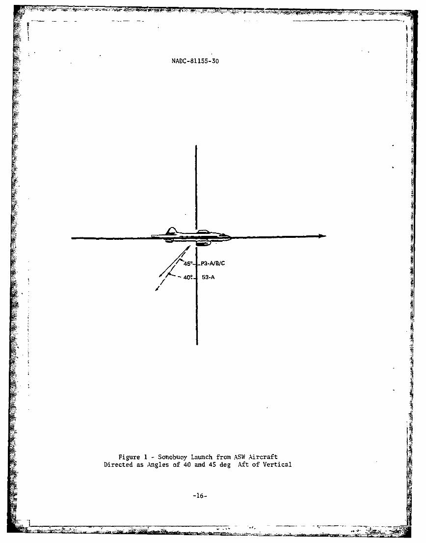
1 Sonobuoy Lauach from ASW Aircraft Directed asAngles of 40 and 45 deg Aft of Vertical .... ...... 16
2 Horizontal Velocities Directed Aft by theAircraft CAD Launchers .... ............... ..... 17
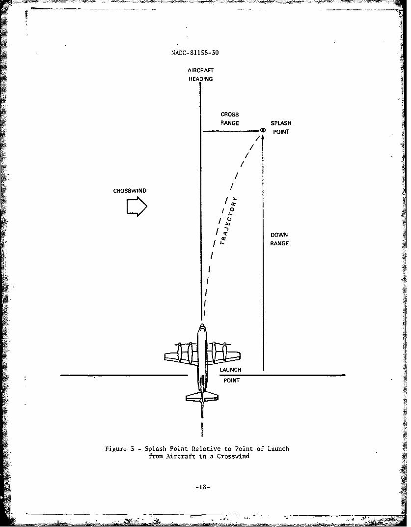
3 Splash Point Relative to Point of Launch fromAircraft in a Crosswind .... .............. .. ... 18
4 Water Entry Velocity as a Function of 8forOne Second Delay cf Decelerator Deploymentand 290 kn Aircraft Speed at Launch ........ ... 19
3 Descent Time as a Function of 8 for One SecondDelay of Decelerator Deplayment for 290 knAircraft Speed at Launch ......... .............. 20
6 Water Entry Velocity as a Function of DeceleratorDeployment Altitude for the AN/SSQ-S3A SonobuoyLaunched from 290 kn Aircraft ... ........... ... 21
7 Wind Profiles ...... ................... ..... 22
8 Down Range as a Function of Ballistic Coefficient,Aircraft Speed, and Launch Altitude for One SecondDelay of Decelerator Deployment .. .......... ... 23
9 Cross Range as a Function of Ballistic Coefficientin a Typical Wind Profile Orthogonal to AircraftHeading, with Aircraft Speed 290 kn and 1 secTime Dely of Decelerator Deployment ........ ... 24
10 Comparison of Splash Point Uncertainty for Launchof the AN/SSQ-S3A Sonobuoy from a 290 kn Aircraftat Different Altitudes in a Typical Wind Profile . 25
Ii Cross Range for Various Decelerator Deplaoyment A
Altitudes for the AN4/SSQ-S3A Sonobuoy in aTypical Crosswind Profile.............. 26
12 Comparison of Splash Point Uncertainty for Launchof ti:e AN/SSQ-53A Sonobuoy from a 290 kn Aircraft
at Different Altitudes in a Typical Wind Profilewith Decelerator Deployment at Launch orat 1000 ft ....... ..................... ..... 27
-4-
- ----!1-~=-~
NADC-811SS-30
SLIST OF FIGURES
Figure No. Page No.
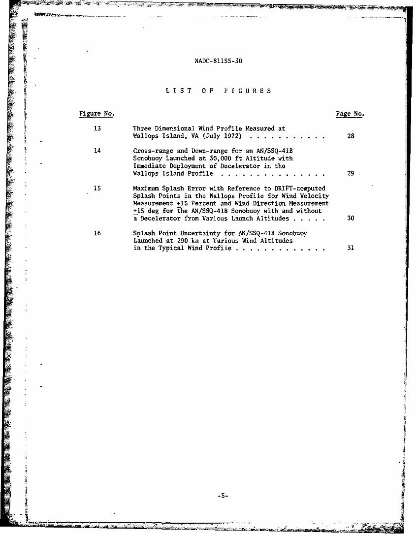
13 Three Dimensional Wind Profile Measured atWallops Island, VA (July 1972) ....... ........... 28
14 Cross-range and Down-range for an AN/SSQ-41BSonobuoy Launched at 30,000 ft Altitude withImmediate Deployment of Decelerator in theWallops Island Profile ... ........... ....... 29
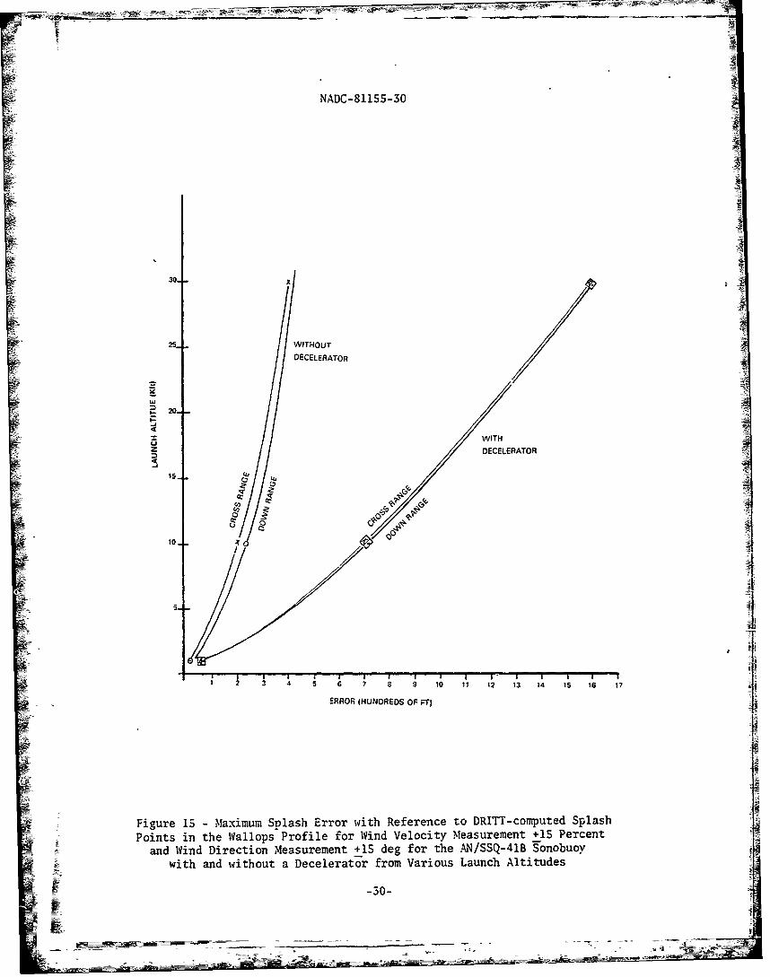
15 Maximum Splash Error with Reference to DRIFT-computedSplash Points in the Wallops Profile for Wind VelocityMeasurement +15 Percent and Wind Direction Measurement+15 deg for the AN/SSQ-41B Sonobuoy with and withouta Decelerator from Various Launch Altitudes ... ..... 30
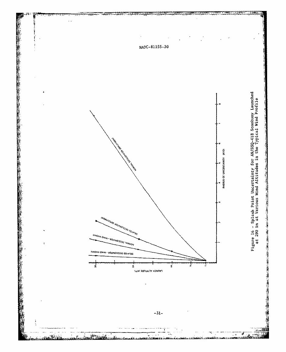
16 Splash Point Uncertainty for AN/SSQ-41B SonobuoyLaunched at 290 kn at Various Wind Altitudesin the Typical Wind Profile .... ............. .... 31
i-5-N :--: -s
NADC-81155-30
LIST OF TABLES
Table No. Page No.
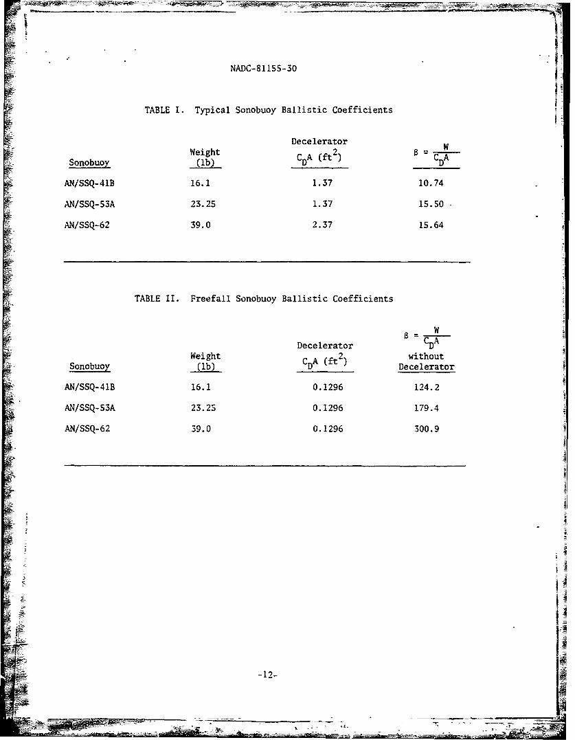
I Typical Sonobuoy Ballistic Coefficients ......... .... 12
II Freefall Sonobuoy Ballistic Coefficients ...... .... 12
III Comparison of Sonobuoy Splash Point Uncertaintyin the Typical Wind Profile ..... .............. .... 13
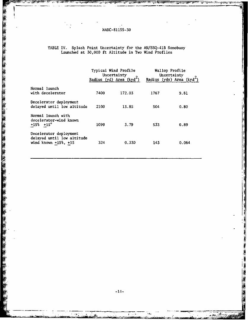
IV Splash Point Uncertainty for the AN/SSQ-41B Sonobuoy 14Launched at 30,000 ft Altitude in Two Wind Profiles
"-6-
~ýM4
)• NADC-811S5-30
LI-
'•DISCUSSION
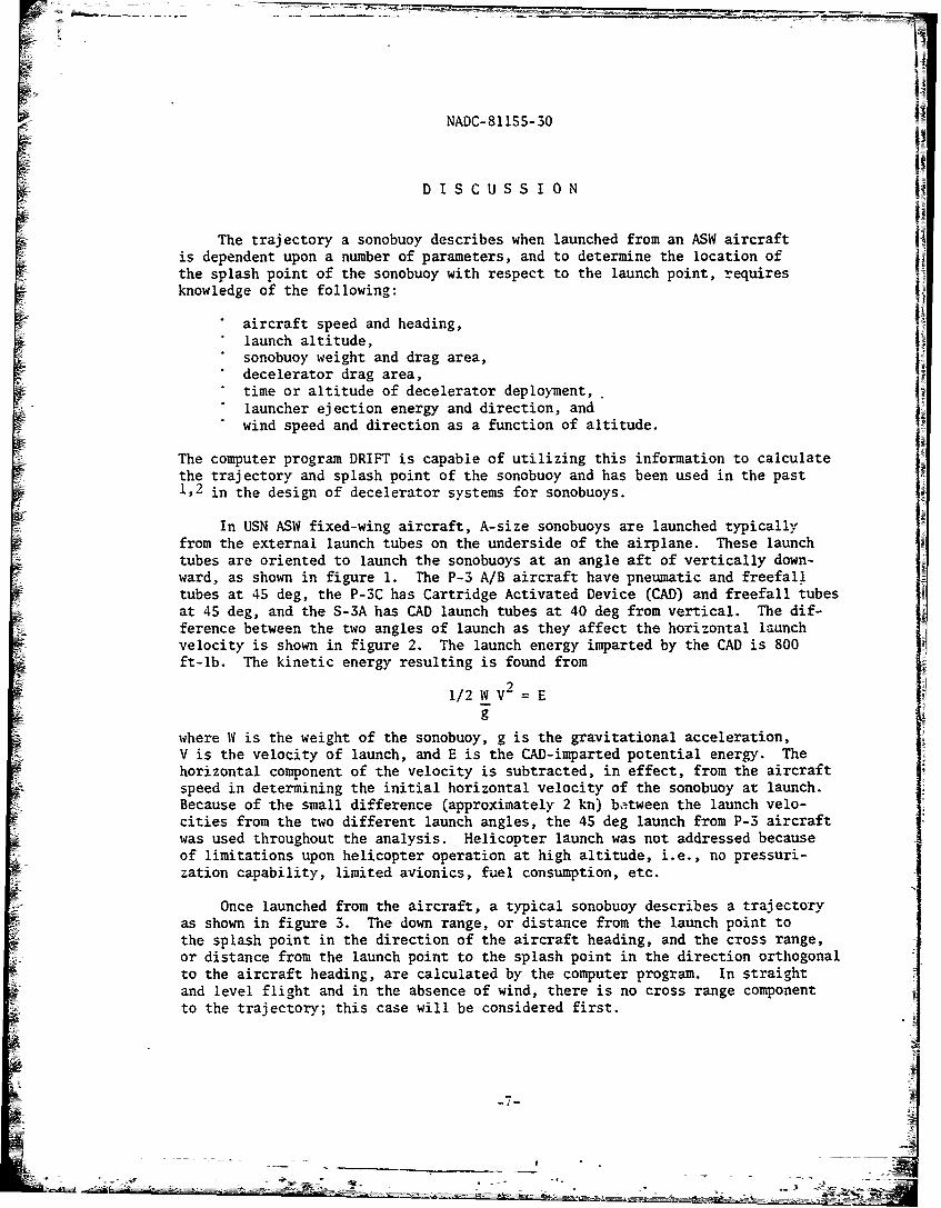
The trajectory a sonobuoy describes when launched from an ASW aircraft lis dependent upon a number of parameters, and to determine the location of !Ithe splash point of the sonobuoy with respect to the launch point, requiresknowledge of the following:
*aircraft speed and heading,*launch altitude,*sonobuoy weight and drag area,
decelerator drag area,time or altitude of decelerator deployment,.
*launcher ejection energy and direction, and ]
*wind speed and direction as a function of altitude.
The computer program DRIFT is capable of utilizing this information to calculateIthe trajectory and splash point of the sonobuoy and has been used in the past1,2 in the design of decelerator systems for sonobuoys.
In USN ASW fixed-wing aircraft, A-size sonobuoys are launched typicallyfrom the external launch tubes on the underside of the airplane. These launchtubes are oriented to launch the sonobuoys at an angle aft of vertically down-ward, as shown in figure 1. The P-3 A/B aircraft have pneumatic and freefall
S~tubes at 45 deg, the P-SC has Cartridge Activated Device (CAD) and freefall tubesat 45 deg, and the S-3A has CAD launch tubes at 40 deg from vertical. The dif-ference between the two angles of launch as they affect the horizontal launchvelocity is shown in figure 2. The launch energy imparted by the CAD is 800ft-lb. The kinetic energy resulting is found from
91/2 IV V- = E
g
where IV is the weight of the sonobuoy, g is the gravitational acceleration,V is the velocity of launch, and E is the CAD-imparted potential energy. Thehorizontal component of the velocity is subtracted, in effect, from the aircraftspeed in determining the initial horizontal velocity of the sonobuoy at launch.Because of the small difference (approximately 2 kn) be~tween the launch velo-cities from the two different launch angles, the 45 deg launch from P-5 aircraftwas used throughout the analysis. Helicopter launch was not addressed becauseof limitations upon helicopter operation at high altitude, i.e., no pressuri-zation capability, limited avionics, fuel consumption, etc.
Once launched from the aircraft, a typical sonobuoy describes a trajectoryas shown in figure 3. Thne down range, or distance from the launch point tothe splash point in the direction of the aircraft heading, and the cross range,or distance from the launch point to the splash point in the direction orthogonal-to the aircraft heading, are calculated by the computer program. In straight-and level flight and in the absence of wind, there is no cross range componentto the trajectory; this case will be considered first.
-I-7•
NADC-81155-30
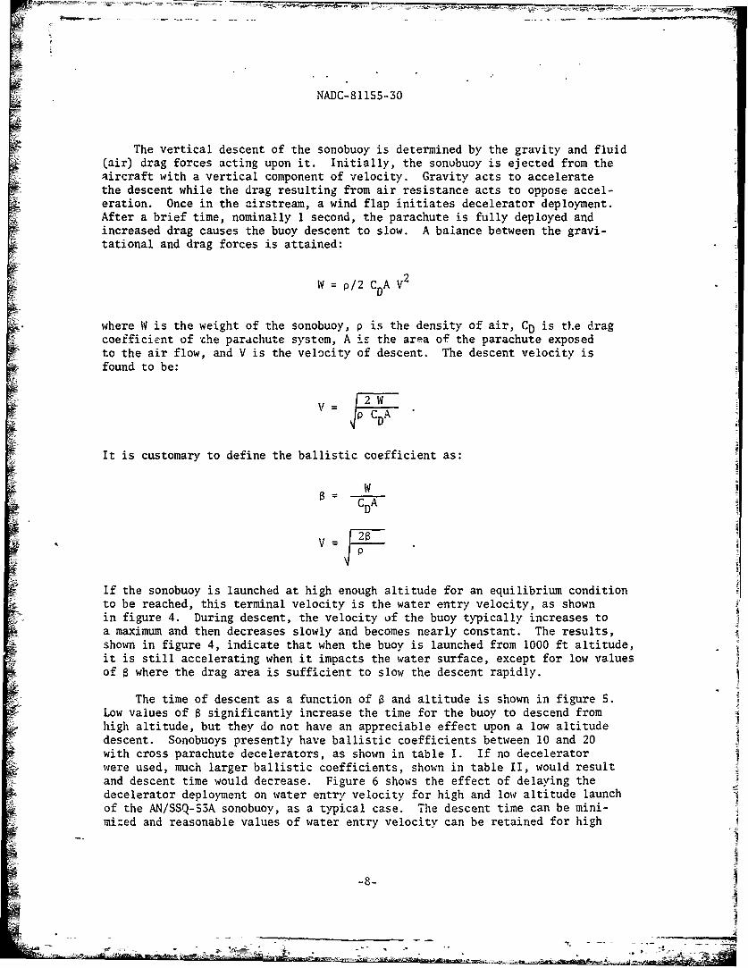
The vertical descent of the sonobuoy is determined by the gravity and fluid(air) drag forces acting upon it. Initially, the sonobuoy is ejected from theaircraft with a vertical component of velocity. Gravity acts to acceleratethe descent while the drag resulting from air resistance acts to oppose accel-eration. Once in the airstream, a wind flap initiates decelerator deployment.After a brief time, nominally 1 second, the parachute is fully deployed andincreased drag causes the buoy descent to slow. A balance between the gravi-tational and drag forces is attained:
9W = P/2 CDA V"
where W is the weight of the sonobuoy, p is the density of air, CD is tlhe dragcoefficient of "he parachute system, A is the area of the parachute exposedto the air flow, and V is the velocity of descent. The descent velocity isfound to be:
It is customary to define the ballistic coefficient as:
8- WC AD
•~ 2=
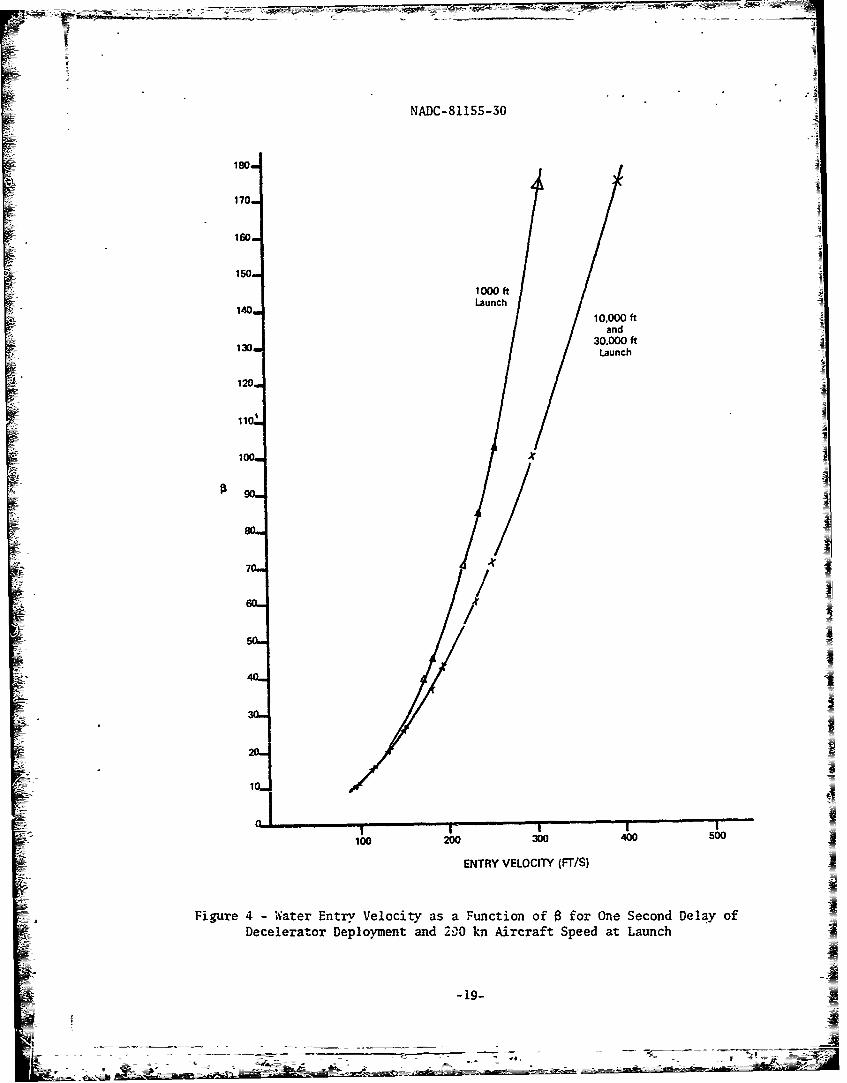
If the sonobuoy is launched at high enough altitude for an equilibrium conditionto be reached, this terminal velocity is the water entry velocity, as shownin figure 4. During descent, the velocity of the buoy typically increases toa maximum and then decreases slowly and becomes nearly constant. The results,shown in figure 4, indicate that when the buoy is launched from 1000 ft altitude,it is still accelerating when it impacts the water surface, except for low valuesof s where the drag area is sufficient to slow the descent rapidly.
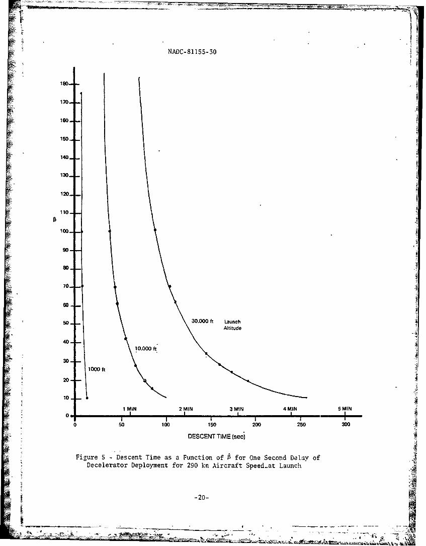
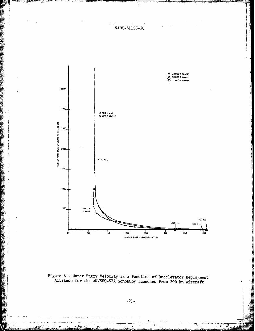
The time of descent as a function of 8 and altitude is shown in figure 5.Low values of 8 significantly increase the time for the buoy to descend fromhigh altitude, but they do not have an appreciable effect upon a low altitudedescent. Sonobuoys presently have ballistic coefficients between 10 and 20with cross parachute decelerators, as shown in table I. If no deceleratorwere used, much larger ballistic coefficients, shown in table II, would resultand descent time would decrease. Figure 6 shows the effect of delaying thedecelerator deployment on water entry velocity for high and low altitude launchof the AN/SSQ-53A sonobuoy, as a typical case. The descent time can be mini-mized and reasonable values of water entry velocity can be retained for high
-8-
NADC-81155-30
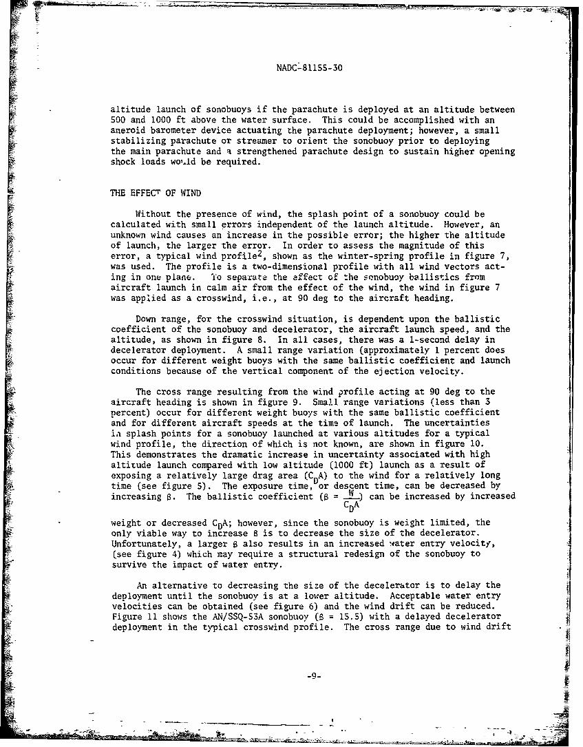
altitude launch of sonobuoys if the parachute is deployed at an altitude between500 and 1000 ft above the water surface. This could be accomplished with ananeroid barometer device actuating the parachute deployment; however, a smallstabilizing parachute or streamer to orient the soncbuoy prior to deployingthe main parachute and a strengthened parachute design to sustain higher openingshock loads wouAd be required.
THE EFFECT OF WIND
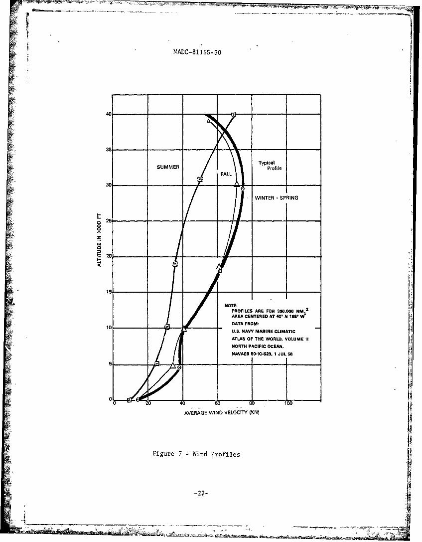
Without the presence of wind, the splash point of a sonobuoy could becalculated with small errors independent of the launch altitude. However, anunknown wind causes an increase in the possible error; the higher the altitudeof launch, the larger the error. In order to assess the magnitude of thiserror, a typical wind profile 2 , shown as the winter-spring profile in figure 7,was used. The profile is a two-dimensional profile with all wind vectors act-ing in one plane. To separate the effect of the sonobuoy ballistics fromaircraft launch in calm air from the effect of the wind, the wind in figure 7was applied as a crosswind, i.e., at 90 deg to the aircraft heading.
Down range, for the crosswind situation, is dependent upon the ballisticcoefficient of the sonobuoy and decelerator, the aircraft launch speed, and thealtitude, as shown in figure 8. In all cases, there was a 1-second delay indecelerator deployment. A small range variation (approximately 1 percent doesoccur for different weight buoys with the same ballistic coefficient and launchconditions because of the vertical component of the ejection velocity.
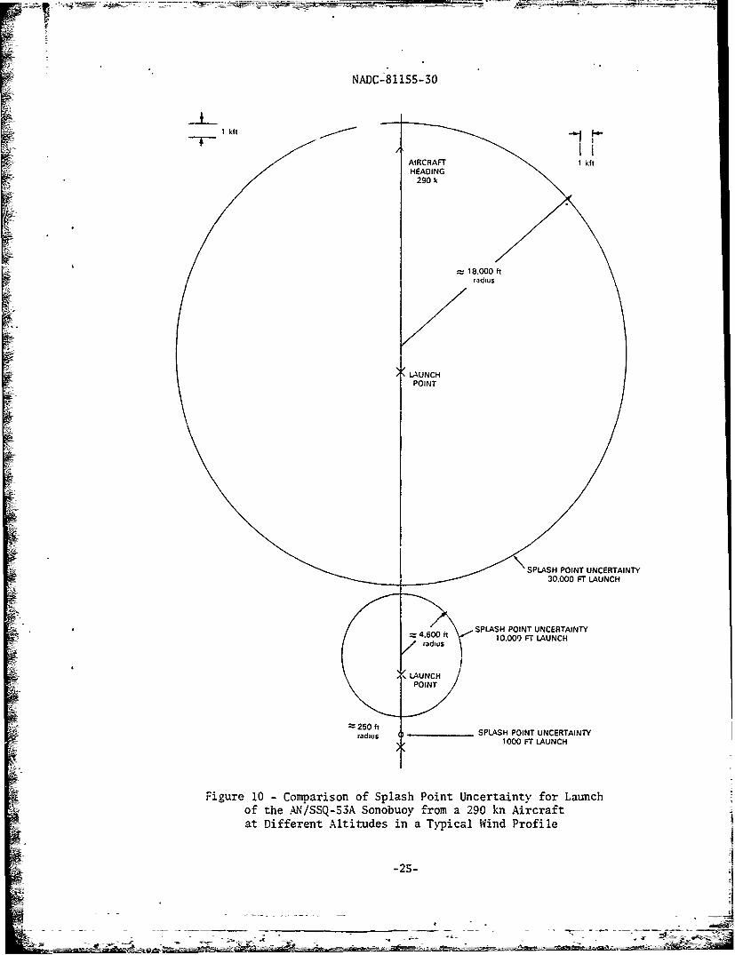
The cross range resulting from the wind profile acting at 90 deg to theaircraft heading is shown in figure 9. Small range variations (less than 3percent) occur for different weight buoys with the same ballistic coefficientand for different aircraft speeds at the time of launch. The uncertaintiesin splash points for a sonobuoy launched at various altitudes for a typicalwind profile, the direction of which is not known, are shown in figure 10.This demonstrates the dramatic increase in uncertainty associated with highaltitude launch compared with low altitude (1000 ft) launch as a result ofexposing a relatively large drag area (CDA) to the wind for a relatively longtime (see figure 5). The exposure time, or descent time, can be decreased byincreasing $. The ballistic coefficient (a = WJ2) can be increased by increased
CDA
weight or decreased CDA; however, since the sonobuoy is weight limited, theonly viable way to increase 6 is to decrease the size of the decelerator.Unfortunately, a larger a also results in an increased water entry velocity,(see figure 4) which may require a structural redesign of the sonobuoy tosurvive the impact of water entry.
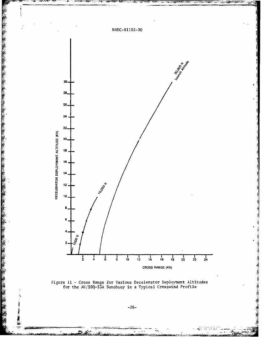
An alternative to decreasing the size of the decelerator is to delay thedeployment until the sonobuoy is at a lower altitude. Acceptable water entryvelocities can be obtained (see figure 6) and the wind drift can be reduced.Figure 11 shows the AN/SSQ-53A sonobuoy (a = 15.5) with a delayed deceleratordeployment in the typical crosswind profile. The cross range due to wind drift
M-9-
NADC-81lI5-30
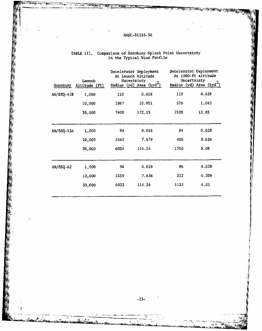
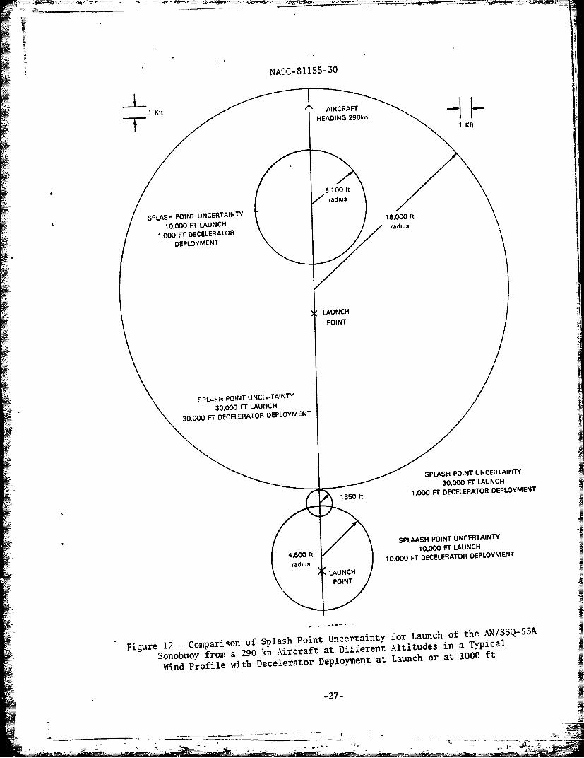
is reduced if the decelerator deployment is delayed until the sonobuoy is ata lower altitude. Figure 12 shows the reduction of the uncertainty area of113 kyd 2 for a 30,000-ft altitude launch of the sonobuoy with immediate decel-erator deployment to an uncertainty area of 9 kyd 2 for the same sonobuoy launch,but with a delay in decelerator deployment until the buoy is at 1000 ft. TableIII compares the splash point uncertainties for three types of sonobuoys launchedfrom various altitudes when the decelerator is deployed immediately or delayeduntil 1000-ft altitude. The AN/SSQ-41B and AN/SSQ-53A have similar character-istics, and the deployed decelerator deployment reduces the range uncertaintyby 70 percent to 72 percent of the undelayed deployment range, and the areauncertainty by 90 percent to 92 percent of the corresponding undeployed deploy-ment are uncertainty. The AN/SSQ-62 with a higher ballistic coefficient tableII) shows an even more significant reduction in splash error.
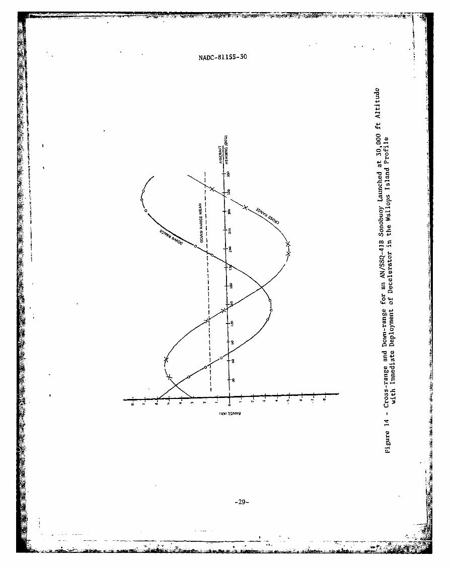
Because of the sparcity of open ocean three-dimensional wind profiles,the two-dimensional typical profile has been used as a standard throughoutthis analysis. However, it is instructive to consider the ":h-se-dimensionalwind profile from the perspective of a real world example. For this purpose,a three-dimensional wind profile obtained at Wallops Island, as shown in fig-ure 13, is used. The sonobuoy is now subjected to a wind which varies in bothspeed and direction with altitude and the effect of the wind is determined byvarying the aircraft heading, as in figure 14. The AN/SSQ-41B launched at30,000 ft from a 290-kn aircraft in the Wallops profile has an uncertaintyradius of approximately 1767 yd, or an area of uncertainty of 9.8 kyd2 . In
the typical wind profile, the same sonobuoy would have a splash point uncer-tainty of 7400 yd radius, or 172 kyd2 area (as in table III). Since the windprofile is not known when the sonobuoy is launched, no assessment of splashpoint accuracy can be made in the aircraft at high altitude except in the broad-est terms available, such as a rule of thumb based on the typical wind profile.
If the instrumentation to measure the wind as a function of altitude(e.g., a wind dropsonde) were available, a reduction of uncertainty would resultin a significantly enhanced capability to make high altitude sonobuoy launchesfor localization. Presently, meteorological wind dropsondes are not compatiblewith ASW aircraft, and dropsondes usable by ASW aircraft do not measure wind.A development would be required to provide ASW aircraft with such a wind mea-suring device. A
Using the Wallops profile as representing a true wind profile, the splashpoint for an AN/SSQ-41B sonobuoy launched from a 290-kn aircraft at variousaltitudes was calculated using the DRIFT program. Splash points were alsocalculated assuming a measured profile which was allowed to var, by +15 percentin magnitude and by +15 deg in direction to simulate measurement system inaccur-acies and short term variations in the wind itself. Figure 15 shows the maximumsplash error (radius) from the DRIFT-calculated point of water entry as a func-tion of launch altitude for the best possible case (without a decelerator) andthe worst case (with the decelerator deployed immediately upon launch). Thereduction in error obtained by delaying the decelerator deployment in the typ-ical wind profile is also observed in the Wallops profile. Table IV summarizesthe various uncertainties for an AN/SSQ-41B sonobuoy launched at 290 kn at 30,000ft for both the typical wind profile and the Wallops profile. in either case,
-10-
NADC-81155-30
the use of a wind measuring device, which could provide wind speed and directionwith altitude to the aircraft's onboard computer, would significantly reducethe uncertainty in sonobuoy location.
The radius of uncertainty for the AN/SSQ-41B sonbuoy launched in a typicalwind profile from a 290-kn aircraft at various altitudes is shown in figure 16,where comparison is made among a standard sonobuoy with decelerator, one inwhich the decelerator deployment is delayed, one with the standard deceleratorwhere the wind is known to +15 percent, and one with delayed decelerator deploy-ment with the wind known to +15 percent. The requirements for accuracy of place-ment for sonobuoys are determined by various factors, depending upon the scenariounder consideration and the quantity of buoys available. If a particular radiusof uncerLainty v.ere required, a sonobuoy could be launched from low altitudewithouw modification or at a higher altitude if the decelerator deployment isdelayea until the buoy has descended to 1,000 ft. If the wind were measured,these launch altitudes might be increased even higher.
-• - --
a S -
NADC-81155-50
TABLE I. Typical Sonobuoy Ballistic Coef£icients
Decelerator wWeight 6 = CD•Sonobuo• (ib) CDA (ft2)
AN/SSQ-41B 16.1 1.57 10.74
AN/SSQ-S3A 23.25 1.37 15.50
AN/SSQ-62 39.0 2.57 15.64
TABLE II. Freefall Sonobuoy Ballistic Coefficients
W •Decelerator CDA
Weight withoutSonobuoy (Ib) CDA (ft2)
DeceleratorSAN/SSQ-41B 16.1 0.1296 124.2 :=
• •N/SSQ-53A 23.25 0.1296 179.4
"• /•I/SSQ-62 39.0 0.1296 300.9
gN
£
-12-
NADJC-81ISS-30
TABLE III. Comparison of Sonobuoy Splash Point Uncertaintyin the Typical Wind Profile
Decelerator Deployment Decelerator DeploymentAt Launch Altitude At 1000-ft altitude
Launch Uncertainty 2Uncertainty 2Sonobuoy Altitude (ft) Radius (yd) Area (kyd) Radius (yd) Area (kyd
AN/SSQ-41B 1,000 110 0.038 110 0.038
10,000 1867 10.951 576 1.042
30,000 7400 172.03 2100 13.85
AN/SSQ-S3A 1,000 94 0.028 94 0.028
10,000 1563 7.679 450 0.636
30,000 6054 115.14 1700 9.08
AN/SSQ-62 1,000 96 0.029 96 0.029
10,000 1559 7.636 312 0.306
30,000 6033 114.34 1133 4.03
NADC-8115S-30
TABLE IV. Splash Point Uncertainty for the AN/SSQ-41B SonobuoyLaunched at 30,000 ft Altitude in Two Wind Profiles
Typical Wind Profile Wallop ProfileUncertainty 2 Uncertainty
Radius (yd) Area (kyd) Radius (yds) Area (kyd2)
Normal launchwith decelerator 7400 172.03 1767 9.81
Decelerator deploymentdelayed until low altitude 2100 13.85 504 0.80
Normal launch withdecelerator-wind known+15% +150 1099 3.79 533 0.89
Decelerator deploymentdelayed until low altitudewind known +15%, +15 324 0.330 143 0.064
-14-
- ~ -- --- ~- ~ -N
NADC-81155-30
REFERENCES
1. Reitz, C.O., "Ballistic Nomographs," NAVAIRDEVCEN Report No. NADC-72187-VT,Dec 1972.
2. Reed, E.A., "Decelerator Design Guidance-A-size Sonobuoys," NAVAIRDEVCENReport No. NADC-72181-VT, Oct 1972.
3. Mack, H., "ASW Aircraft Operating and Sonobuoy Launching Characteristics,"NAVAIRDEVCEN Report No. NADC-74086-30, Jun 1974.
A ACKNOWLEDGEMENT
The author wishes to thank Mssrs. John Yocom, Tim Kraynak, and Gary Whitmanfor their contributions in the adaptation and utilization of the DRIFT computerprogram in support of this effort.
-IS-
i°°g- i_-
NADC-811S5-30
•//45O P3-A/B/C
i4! 5 3-A
Figure 1 - Sonobuoy Launch from ASIV Aircraft I
Directed as Angles of 40 and 45 deg Aft of Vertical
-16-

NADC-8115-30
45-
40-
35-
~300
20 j
I.U
S~45 deg
from vertical
10 I I I I I"Ii10 15 20 25 30 35 40
SONOBUOY WEIGHT (LB)
Figure 2 - Horizontal Velocities Directed Aftby the Aircraft CAD Laimchers
NADC-81155-30
AIRCRAFT
HEADING
CROSS
RANGE SPLASH
0 POINT
) /
CROSSWIND t
DOWN
RANGE
tI
N- I
SPOINT
II
Figure .3 - Splash Point Relative to Point of Launchfrom Aircraft in a Crosswind
-18-
NADC-81155-30
1S0
170
160-
150.1000 ft
140.,, Launch
and
30.000 ft130- Launch
120
11W,
707
v20
ENTRY VELOCITY (FT/S)
Figure 4 - Water Entry Velocity as a Function of 0 for One Second Delay ofDecelerator Deployment and 2,O kn Aircraft Speed at Launch
•i -19-
NADC-81IS5-30
17"0
160
150
140
130
120
110
100
s0
80
70-
60
5030,000 ft Launch
Altitude
4010.000 ft
I MIN 2 MIN 3 MIN 4 MIN 5 MIN04
0 so 100 150 200 250 300
DESCENT TIME (sec)
Figure 5 -Descent Time as a Function of ý for One Second Delay ofDecelerator Deployment for 290 kn Aircraft Speed-at Launch
- 20-
NAIC-81155-30
A 30 000 i .L&,nCh
X 10000ttftn.Ch1 000 It Lsnch
3000-
10000 It S~d30000 ft LA&flCh
S2500
2
~2000-
-- N •"lT fti
15w-
1000 -I
500 10010 1
326 397 *tos .4
WATER ENTRY VELOCITY iFT/SI
Figure 6 -Water Entry Velocity as a Function of Decelerator DeploymentAltitude for the AN/SSQ-53A Sonobuoy Launched from 290 kn Aircraft
_ I ..o_
NADC-81155-30
40
Al
35.
TypicalSUMMER FALL Profile
I FALL
; WINTER - SPRING
o 2E
250
2-j
NOTE:PROFILES ARE FOR 390.000 NMC
2
AREA CENTERED AT 40- N 168 W9
I- uDATA FROM:10U.S. NAVY MARINE CIUMATIC
ATLAS OF THE WORLD. VOLUME 11NORTH PACIFIC OCEAN,
NAVAER 50-IC-523. 1 JUL66
°0
0 20 40 60 80 100
AVERAGE WIND VELOCITY (KN)I i-Figure 7 - Wind Profiles I
a- -a -J

NADC-81155-30
u 0
4J:.
041
~44-
..- 0
4J
C,*
o00
09e~
4J0
001> 0z )
04 J
0 u
"-I CIS
0)
'0 0-
-23-

NADC-81' 55-30
Cd1r- 41
0 -
(44 0
cz
-4
-4.~'44
cci
C44
ca
00V
4J
-4J
Otn
2 4J5-
zi 0
ME-_~~ -4 ýý-g
NADC-81155-30
I kft•iAIRCRA.r I kft
SHEADING290 k
10.000 FTftNC
radius
•, LAUNCHPOINT
S PLASH P OINT UNCERTAINTY1' 30.000 FT LAUNCH
SPLASH POINT UNCERTAINTY10,00) FT LAUNCH
-250 ftStadius )SPLASH POINT UNCERTAINTY•i• 1000 FT LAUNCH
•_Figure 10 -Comparison of Splash Point Uncertainty for Launch• of the .N/SSQ-S3A Sonobuoy from a 290 kn Aircraft:• at Different Altitudes in a Typical WVind Profile
-<N -2s-
NADC-81155-30
30.-
28.
26- ,
24-,
22- ,
'U 20- -
0
18
c-
z
'U
S16-
4-• 0.'U14-
-I
2
2 4 6 8 10 12 14 16 18 20 22 24
CROSS RANGE (Kft)
i• Figure 11 Cross Range for Various Decelerator Deployment Altitudesi for the A•NI/SSQ-S3A Sonobuoy in a Typical Crosswind Profile
-26-
'U A
---------
NADC-8115 5 - 30
SI Kit , AIRCRAFT
T HEADING 290kn
• 1 Kft
• • /radius
SPLASH POINT UNCERTAINTY 18.000 ft
10.000 FT LAUNCH
1.000 FT DECELERATOR radius
DEPLOYMENT
LAUNCHPOINT
SPLPH POINT UNC rTAINTY
30.000 FT LAUNCH
30.000 FT DECELERATOR DEPLOYMENT
SPLASH POINT UNCERTAINTY
30,000 FT LAUNCHS 1350 ft 1.000 FT DECELERATOR DEPLOYMENT
SPLAASH POINT UNCERTAINTY10.000 FT LAUNCH
4.600 ft 10,000 FT DECELERATOR DEPLOYMENTradius ,!LUC
Figure 12 - Comparison of Splash Point Uncertainty for Launch of the XN/SSQ-S3A
Sonobuoy from a 290 kn Aircraft at Different Altitudes in a Typical
Wind Profile with Decelerator Deployment at Launch or at 1000 ft
-27-

NADC-81155-30
0 0e{
S S 0U)
- o
$4 -4
1 41
-28-;2
_ _ _ _ _ _ _ I
- ---- -
NADC-81 155-30
414.)
*44cc 0
cov
0
"-4
CY0z
fn4J
04-44-4 0
0Ž~0
O'K a) 10
II to -)
ulA) 3DtIvU
I-4
-29-
NADC-81155-30
30- x
25-- WITHOUT
DECELERATOR
t20-
WITH
UL
2' DECELERATOR 0' 1 1 13 14 14 76 1
1RO6HNRESO T
-30
NADC- 81155-30
0
-o 4
"0~d
60
00
443
4J
a 4z
4.)-
r.4j
&040
k4O~ i
lio4I 3oni:lIV HDNflvi
- 31-.