Embed Size (px)
Citation preview

CONFIDENTIAL © Copyright 2012. Aruba Networks, Inc. All rights reserved 1
HIGH DENSITY WIRELESS NETWORKSVALIDATED REFERENCE DESIGN (VRD)
CONFIDENTIAL © Copyright 2011. Aruba Networks, Inc. All rights reserved
Chuck LukaszewskiSenior Director, Professional [email protected]

2 2CONFIDENTIAL © Copyright 2012. Aruba Networks, Inc. All rights reserved
Agenda
• Capacity Planning for HD WLANs
• RF Design for HD WLANs
• Optimizing and Configuring ArubaOS
• Case Study #1 – Marina Bay Sands Singapore
• Case Study #2 – Turner Field

CONFIDENTIAL © Copyright 2012. Aruba Networks, Inc. All rights reserved 33CONFIDENTIAL © Copyright 2012. Aruba Networks, Inc. All rights reserved
Capacity Planning for High-Density WLANs

4 4CONFIDENTIAL © Copyright 2012. Aruba Networks, Inc. All rights reserved
Aruba Validated Reference Designs
Aruba High-Density Wireless Networks for
Auditoriums
Solu
tion
Gui
de
• Aruba is the thought leader in our industry. We produce a library of Validated Reference Designs
• The High Density (HD) WLANs VRD covers ultra high capacity spaces such as auditoriums, arenas, stadiums and convention centers
• The recommendations have been field proven at dozens of customers
• VRDs are free to download from Aruba Design Guides web page:
http://www.arubanetworks.com/VRD

5 5CONFIDENTIAL © Copyright 2012. Aruba Networks, Inc. All rights reserved
High Density Area Challenges
• Uncontrolled mix of device types, operating systems, driver levels, and radio types
• Multiple devices per person – up to three• Per-user bandwidth needs can easily exceed
what is allowed by WiFi and physics• Simultaneous data plane spikes during
roomwide events (slide advance, polling)• Inrush/outrush demand increases load on
network control plane, address space, etc.• Power save behavior also loads control plane• Most devices limited to 1x1:1 HT20 operation

6 6CONFIDENTIAL © Copyright 2012. Aruba Networks, Inc. All rights reserved
HD WLAN Capacity Planning Methodology

7 7CONFIDENTIAL © Copyright 2012. Aruba Networks, Inc. All rights reserved
Step 1: Determine Device Count
• Choosing a high-density WLAN capacity goal: – Total # of devices = seats X devices per seat
• A user may have a laptop & Wi-Fi smartphone• Each MAC address uses airtime, IP address, etc.
– Minimum bandwidth per device – driven by mix of data, voice and video applications used
– Common examples of a complete capacity goal:• Classroom has 30 students each needs 2 Mbps• Auditorium holds 500 people w/laptop at 350 Kbps for data and a
voice handset at 128 Kbps• Trading floor of 800 people with 512 Kbps each
– Try to plan for future capacity needs in the design– Number of seats may remain fixed, but number of devices
may continue to proliferate

8 8CONFIDENTIAL © Copyright 2012. Aruba Networks, Inc. All rights reserved
Stacking/ReusingChannels
Overlapping ChannelsOverlapping ChannelsSingle Channel
Step 2: Determine Channel CountOverlapping vs. Stacking
HD WLANs should always use the 5-GHz band for primary client service Client chipset/driver also impact supported channels

9 9CONFIDENTIAL © Copyright 2012. Aruba Networks, Inc. All rights reserved
Step 2: Determine Channel CountChannels Allowed by National Regulatory Agency
• Channel bonding (HT40) reduces capacity in HD WLANs, so 20MHz channels should always be used in both bands
• Available channel count varies from country to country
• DFS channels have usability restrictions and may not be a good choice

10 10CONFIDENTIAL © Copyright 2012. Aruba Networks, Inc. All rights reserved
Step 2: Determine Channel Count20 MHz vs. 40 MHz Channels
• High-throughput 40-MHz (HT40) channels – Reduces number of radio channels by bonding them together
to achieve higher throughput– Reduced max. number of client devices supported– HT40 channels not used on the 2.4-GHz band– Main benefit — ability to burst at the max. PHY
• But, auditoriums must support so many users in a single room that every possible channel is needed– Trade-off: Reduce max. burst rate in exchange for a
greater total user capacity• Therefore, most HD WLANs including auditoriums
should use 20-MHz channel widths, also known as HT20

11 11CONFIDENTIAL © Copyright 2012. Aruba Networks, Inc. All rights reserved
Step 2: Determine Channel Count To DFS or Not to DFS?
• The DFS 5-GHz band, with up to twenty 20-MHz channels, can achieve high performance in a 500-seat auditorium
• Without DFS, the goal can be achieved but with oversubscribed radios & lower per-client throughput
So why wouldn’t everyone use DFS? • Three significant exceptions could adversely affect
HD WLAN performance with DFS enabled: – Proximity to radar sources in the 5250-MHz to 5725-MHz band– Lack of DFS support on critical client devices– The Receive Sensitivity Tuning-Based Channel Reuse feature of
ArubaOS is needed

12 12CONFIDENTIAL © Copyright 2012. Aruba Networks, Inc. All rights reserved
Step 3: Choose Concurrent User TargetAruba High Density Testbed
• Environment – Open air test
• Clients - 50 late-model laptops with mix of manufacturers, OS and wireless adapter/driver
• Goal – Mimic the uncontrolled, heterogeneous environment that exists in most auditoriums
• Procedure – Run scaling tests from 1 to 50 clients and measure how throughput changes with load

13 13CONFIDENTIAL © Copyright 2012. Aruba Networks, Inc. All rights reserved
Step 3: Choose Concurrent User TargetMeasured 20MHz Channel Capacity
5-GHz Aggregate Mixed-Mode TCP Client Scaling Performance
14 14CONFIDENTIAL © Copyright 2012. Aruba Networks, Inc. All rights reserved
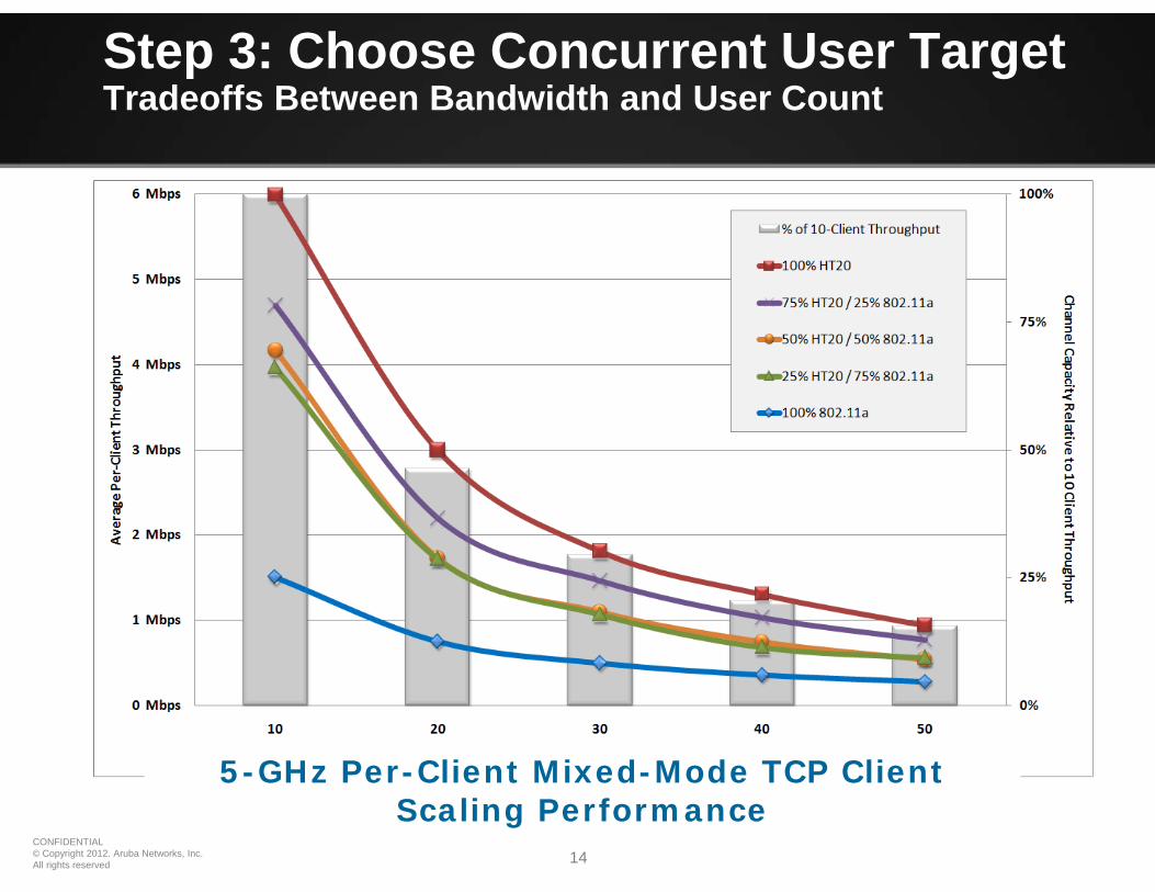
Step 3: Choose Concurrent User TargetTradeoffs Between Bandwidth and User Count
5-GHz Per-Client Mixed-Mode TCP Client Scaling Performance

15 15CONFIDENTIAL © Copyright 2012. Aruba Networks, Inc. All rights reserved
Step 3: Choose Concurrent User TargetRelative Performance of Channel Mixes
5-GHz Per-Client Mixed-Mode TCP Client Scaling Performance

16 16CONFIDENTIAL © Copyright 2012. Aruba Networks, Inc. All rights reserved
Step 4: Determine Total Capacity
US40/20 MHz
w/o DFS
US40/20 MHzwith DFS
EU40/20 MHz
w/o DFS
EU40/20 MHzwith DFS

17 17CONFIDENTIAL © Copyright 2012. Aruba Networks, Inc. All rights reserved
Channel Reuse RevisitedChoosing the Lesser Evil
Speed(fewer APs)
Slots(more APs)
Signal(more APs)

18 18CONFIDENTIAL © Copyright 2012. Aruba Networks, Inc. All rights reserved
Step 5: Validate Capacity Goal
• Validate whether the entire HD coverage area will meet the capacity goal you chose in Step #1.
• It is common for the wireless architect to have to follow an iterative process and compromise between channel count, radio loading and minimum per-client throughput.
• If the capacity prediction in Step #4 falls short of the capacity goal, repeat the first four steps until you achieve the best balance to achieve your goal.
• For large auditoriums over 500 seats, you should be prepared to accept a per-client throughput of 500 Kbps or less, assuming a 50/50 mix of .11n and .11a stations and nine usable channels.

CONFIDENTIAL © Copyright 2012. Aruba Networks, Inc. All rights reserved 1919CONFIDENTIAL © Copyright 2012. Aruba Networks, Inc. All rights reserved
RF Design forHigh-Density WLANs

20 20CONFIDENTIAL © Copyright 2012. Aruba Networks, Inc. All rights reserved
Coverage Strategies for Auditoriums
Overhead coverage is a good choice when uniform signal is desired everywhere in the auditorium
By far the best coverage strategy for auditoriums is mounting under, in, or just above the floor.
Wall installations are most often seen where ceiling or under-floor access is not possible or too expensive.

21 21CONFIDENTIAL © Copyright 2012. Aruba Networks, Inc. All rights reserved
Overhead Coverage — RF Radio Patterns
E-Plane Antenna Pattern of AP-ANT-16 produces a coverage pattern shaped like a “cone”
underneath the antenna.

22 22CONFIDENTIAL © Copyright 2012. Aruba Networks, Inc. All rights reserved
Picocell Coverage - Link Budget Analysis
Picocell link budget formulaPRX = PTX – Lfreespace – Lfloor – Lbody + GTX + GRX

23 23CONFIDENTIAL © Copyright 2012. Aruba Networks, Inc. All rights reserved
• Channel reuse not possible.• Inconsistent signal levels.• Increased body attenuation.• Harder to control CCI/ACI.• Signal bleed outside area.
AP Coverage Strategies – Pros and Cons
OverheadCoverage
• Can be concealed inside ceiling.• Mounted above eye level.• Uniform signal, APs evenly spaced.• Clear line-of-sight to devices.• Minimal human-body attenuation.• Better CCI/ACI control.
PROs CONsStrategy• Channel reuse not possible.• Difficult to pull cable.
SideCoverage
• Easy to install and pulling cable.• Columns can be used to deliberately
create RF shadows.
• Access underneath the auditorium.
• Availability of cable pathways beneath the floor.
FloorCoverage
• Channel reuse possible.• Higher AP densities can be achieved.• APs can be easily concealed.• More uniform signal in the room.• Clear line-of-sight to devices.• Minimal human-body attenuation.• Better CCI/ACI control.

24 24CONFIDENTIAL © Copyright 2012. Aruba Networks, Inc. All rights reserved
Adjacent HD WLANs
AP-105 Integrated Directional Antenna to Isolate Adjacent HD WLANs

CONFIDENTIAL © Copyright 2012. Aruba Networks, Inc. All rights reserved 2525CONFIDENTIAL © Copyright 2012. Aruba Networks, Inc. All rights reserved
Optimizing & Configuring ArubaOSfor High-Density WLANs

26 26CONFIDENTIAL © Copyright 2012. Aruba Networks, Inc. All rights reserved
Essential Aruba Features for HD WLANs
• Even distribution of channels w/ARM
• Enable load-aware, voice-aware, video-aware scanning
• Repurpose unneeded 2.4-GHz radios with Mode-Aware ARM or static assignment
• Enable DFS channels if used
OptimalChannelDistribution
OptimalAirtimeManagement
• Ensure equal access to medium w/Airtime Fairness feature
• Limit “chatty” protocols
• Enable Multicast Rate Optimization and IGMP Snooping
• Enable Dynamic Multicast Opt. for video
• Eliminate low legacy rates by reducing rate adaptation
• Shift all 5-GHz capable devices off 2.4-GHz band w/Band Steering
• Even distribution of clients w/Spectrum Load Balancing
OptimalClientDistribution
OptimalPowerControl
• Restrict maximum allowable EIRP w/ARM to minimize cell overlap
• Control power on clients w/802.11h TPC
• Minimize CCI and ACI w/Receive Sensitivity Tuning Channel Reuse

27 27CONFIDENTIAL © Copyright 2012. Aruba Networks, Inc. All rights reserved
Optimal Channel Distribution
• Optimize the distribution of RF spectrum to APs and clients to make best use of scarce spectrum– Use as many allowed RF channels as possible and ensure
they are properly distributed• ARM Channel Selection
– Aruba ARM uses distributed channel reuse mgmt. algorithm– This iterative process converges quickly on optimum channel
plan for the entire network• Mode-Aware ARM
– Dynamically shifts surplus radios in the same RF neighborhood to become air monitors
– Mode-Aware ARM is disabled by default– APs cannot be individually configured for Mode-Aware

28 28CONFIDENTIAL © Copyright 2012. Aruba Networks, Inc. All rights reserved
Optimal Client Distribution
• Employ ARM to optimally distribute clients between frequency bands
• Band Steering:– Enterprise WLANs have both 2.4-GHz & 5-GHz
bands. But, most clients connect at 2.4 GHz, even if it is the most crowded.
– Solution — HD WLAN “steers” 5-GHz clients to that band reducing contention for 2.4-GHz band.
0.0
10.0
20.0
30.0
40.0
50.0
60.0
70.0
.11b .11g .11a .11n
Effect of band steering on throughput (Mbps)
Before Band Steering With Band Steering
Effect of band steering on data throughput
• Spectrum Load Balancing:– Spectrum load balancing moves clients away
from congested APs or RF channels into those with available capacity.
– The number of clients on a given channel, rather than per-AP is the dominant predictor of data capacity.

29 29CONFIDENTIAL © Copyright 2012. Aruba Networks, Inc. All rights reserved
Optimal Airtime Management
• Ensuring equal access with Airtime Fairness– Maintain application performance in high-density areas with
scheduled airtime fairness
• Limiting “Chatty” protocols– Use ACLs and controller settings to restrict traffic
• Enabling Multicast Rate Optimization– ARM can reduce medium multicast traffic time
• Enabling Dynamic Multicast Optimization for video– Deliver multicast frames with unicast headers, improving reliability
over the air, QoS, and channel utilization
• Limiting supported data rates:– 48 and 54 Mbps for 802.11a/g– 6.5 and 11 Mbps for 802.11b

CONFIDENTIAL © Copyright 2012. Aruba Networks, Inc. All rights reserved 3030CONFIDENTIAL © Copyright 2012. Aruba Networks, Inc. All rights reserved
Case Study #1
Marina Bay Sands Singapore&
Young Presidents Asia Conference

31 31CONFIDENTIAL © Copyright 2012. Aruba Networks, Inc. All rights reserved
Marina Bay Sands Overview
• Huge convention center located in Singapore• 5 levels of convention halls• Grand ballroom on level 5• Can be over 5000 users per level• No control over client devices—can be any type
of device• Distribution of 2.4 GHz and 5.0 GHz clients
changes from one event to another

32 32CONFIDENTIAL © Copyright 2012. Aruba Networks, Inc. All rights reserved
Marina Bay Sands Level 4 possible capacity
800 pax800 pax 800 pax 800 pax
800 pax
1000 pax 1000 pax 1000 pax 1000 pax
400 pax 200 pax
150 pax
Over 8000 total users possible

33 33CONFIDENTIAL © Copyright 2012. Aruba Networks, Inc. All rights reserved
Marina Bay Sands Level 4 Single Room

34 34CONFIDENTIAL © Copyright 2012. Aruba Networks, Inc. All rights reserved
MBS Technical Requirements
• Dynamic configuration required that can be adapted easily to conference events
• SSID’s offered and areas of coverage changes from one event to the next
• Might be only 1 AP needed for one event, while for large events all AP’s must be enabled for coverage and to support expected client density
• Conference goers may bring in their own AP’s that interfere with the MBS service

35 35CONFIDENTIAL © Copyright 2012. Aruba Networks, Inc. All rights reserved
MBS Design - Level 4
• Series of rooms that are largely self contained user spaces• Channel reuse within each room is not possible• 2.4 GHz channels are statically set to ensure 3 non-overlapping
channels per room• 2.4 GHz transmit power is statically set to 15 dBm• 5.0 GHz channels and transmit power are automatically
configured with ARM—ARM has configured all AP’s to use max power
• Signal overlap from one room to the next is minimal• Interference is minimal• Ceiling placement gives Line of Sight (LOS) to clients and
provide strong coverage• SNR is strong within each room giving excellent performance

36 36CONFIDENTIAL © Copyright 2012. Aruba Networks, Inc. All rights reserved
Channel 1 Channel 6 Channel 11 5GHz only
MBS RF Plan – Level 4
• 45 Aruba AP135• Each room can offer up to 3 AP’s on 2.4 GHz

37 37CONFIDENTIAL © Copyright 2012. Aruba Networks, Inc. All rights reserved
MBS Design - Level 5
• Grand ballroom is on level 5• Client density requires more AP’s while vast open area mean
AP’s hear each other quite well• To handle user count channel reuse is mandatory• 2.4 GHz channels are statically configured in grand ballroom and
pre-function foyer to ensure adjacent AP’s are on different channels
• Interference from Audio-Visual system on 2.4 GHz is significant in Grand ballroom
• 5.0 GHz channels and transmit power are configured via ARM• Ceiling placement gives Line of Sight (LOS) to clients and
provide strong coverage• SNR is strong within each room giving excellent performance

38 38CONFIDENTIAL © Copyright 2012. Aruba Networks, Inc. All rights reserved
MBS Level 5 - Possible User Capacity
Over 6000 total users possible
5000 pax
500 pax
800 pax

39 39CONFIDENTIAL © Copyright 2012. Aruba Networks, Inc. All rights reserved
MBS Level 5 – RF Design
AP’s hear each other quite well in Grand ballroom making channel reuse difficult

40 40CONFIDENTIAL © Copyright 2012. Aruba Networks, Inc. All rights reserved
MBS in Action - YPO Asia EventAirWave Connection Report

41 41CONFIDENTIAL © Copyright 2012. Aruba Networks, Inc. All rights reserved
MBS in Action - YPO Asia EventAirWave User Count & Bandwidth Report
42 42CONFIDENTIAL © Copyright 2012. Aruba Networks, Inc. All rights reserved
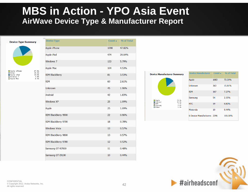
MBS in Action - YPO Asia EventAirWave Device Type & Manufacturer Report

43 43CONFIDENTIAL © Copyright 2012. Aruba Networks, Inc. All rights reserved
MBS in Action - YPO Asia EventAirWave Client Session Summary
Client Session Summary

44 44CONFIDENTIAL © Copyright 2012. Aruba Networks, Inc. All rights reserved
MBS in Action - YPO Asia EventAirWave Max Concurrent Client Report
CONFIDENTIAL © Copyright 2012. Aruba Networks, Inc. All rights reserved 4545CONFIDENTIAL © Copyright 2012. Aruba Networks, Inc. All rights reserved
Case Study #2
Turner Field – Atlanta

46 46CONFIDENTIAL © Copyright 2012. Aruba Networks, Inc. All rights reserved
“Up and Out” RF Design
• Three interleaved “blankets” of APs to cover the lower sections, club level, and upper sections respectively:– Lower deck antennas are mounted under the club seats and
aimed “out” to the field– Upper deck antennas are mounted underneath the floor and
aimed straight “up” through the concrete. In the middle– A blanket of APs is installed in the club suites above the
ceiling.
• The stadium structure itself is used to minimize interference between blankets
46

47 47CONFIDENTIAL © Copyright 2012. Aruba Networks, Inc. All rights reserved
RF Design – 3 Independent RF “Blankets”
47

48 48CONFIDENTIAL © Copyright 2012. Aruba Networks, Inc. All rights reserved
RF Design – Full Scale 3D Model
48

49 49CONFIDENTIAL © Copyright 2012. Aruba Networks, Inc. All rights reserved
Physical Installation – Lower Blanket
APs mounted directly above the 200 sections, with 30ºx30º high gain directional antennas aimed at row 10
49

50 50CONFIDENTIAL © Copyright 2012. Aruba Networks, Inc. All rights reserved
Physical Installation – Upper Blanket
APs mounted underneath 400 sections, with dual 60ºx60ºdirectional antennas aimed to match slope of stands

51 51CONFIDENTIAL © Copyright 2012. Aruba Networks, Inc. All rights reserved
Typical AirMagnet Survey – Ch 6 – SNR
20dBSNR
25dBSNR
10dBSNR

52 52CONFIDENTIAL © Copyright 2012. Aruba Networks, Inc. All rights reserved
Typical Picocell RF Rolloff – 3D Side View
52
Increase in TX power concentrated directly above AP, with smooth roll-off expanding cell slightly side-to-side
Views are filtered for RSSI at -72dBm or higher
View is as if standing on top of section 18, looking down at field
Steep fall-off is due to steel
beam next to AP
APs must be mounted
midway between beams for
optimal signal dispersal

53 53CONFIDENTIAL © Copyright 2012. Aruba Networks, Inc. All rights reserved
Typical WaveDeploy Throughput Test
• WaveDeploy is a new WiFivalidation tool from VeriWave
• Multiple test clients, mix-and-match– Lightweight native agent for
each OS– Fully automated test console– Able to run TCP, UDP, voice,
video tests and more• An iPad, iPhone 3GS and
Windows 7 laptop were tested by Aruba

54 54CONFIDENTIAL © Copyright 2012. Aruba Networks, Inc. All rights reserved
Typical WaveDeploy TCP Speed Test
• Tests were worst case (device on top of aluminum bench)• iOS devices use different throughput scale than laptop• Performance correlates well with measured RF cell size• Downstream performance generally better than upstream
Win7 Laptop iPad iPhone 3GS
Ups
trea
mD
owns
trea
m

CONFIDENTIAL © Copyright 2012. Aruba Networks, Inc. All rights reserved 5555
Thank You