Embed Size (px)
Citation preview
The Rechargeable Battery Company
®
High Energy Rechargeable
Li-S Battery Development at
Sion Power and BASF
Y. Mikhaylik*, C. Scordilis-Kelley*, M. Safont*, M. Laramie*, R. Schmidt**, H. Schneider**,
K. Leitner**
*Sion Power Corporation, **BASF SE
1 IBA2013, Barcelona, March11-15

®
2
Outline
Fundamentals of Li-S electrochemical system.
Current status of 350 Wh/kg Sion Power cells and their
high power and extreme low temperature variations.
Sion Power and BASF approach for next generation of
Li-S technology.
2 IBA2013, Barcelona, March11-15
®
3
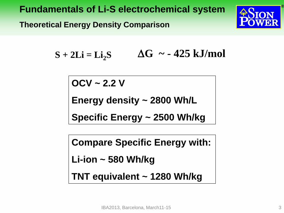
Fundamentals of Li-S electrochemical system Theoretical Energy Density Comparison
DG ~ - 425 kJ/mol
OCV ~ 2.2 V
Energy density ~ 2800 Wh/L
Specific Energy ~ 2500 Wh/kg
Compare Specific Energy with:
Li-ion ~ 580 Wh/kg
TNT equivalent ~ 1280 Wh/kg
S + 2Li = Li2S
IBA2013, Barcelona, March11-15

®
4
1.8
2.0
2.2
2.4
0.00 0.25 0.50 0.75 1.00 1.25 1.50
Electrons per S atom
Vo
lta
ge
1256 mAh/g
1
2
3
4
Voltage Deep due to
Li2S Nucleation
Polarization
1. Slightly soluble elemental
sulfur reduction to soluble Li2S8
S8 + e- + Li+ Li2S8
2. Soluble Li2S8 reduction to
soluble Li2S4
Li2S8 + e- + Li+ Li2S4
3. Soluble Li2S4 reduction to
solid Li2S and partially Li2S2
Li2S4 + e- + Li+ Li2S+Li2S2
4. High polarization due to
exhaustion of soluble Li2S4 and
porosity blocking by solid Li2S
Up to 1500 mAh/g capacity can
be gained at rates below C/50
Typical Li-S cell discharge profile at room
temperature and rates C/10 - C/2
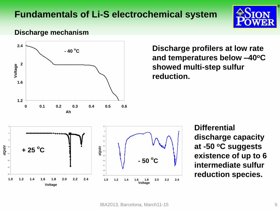
Fundamentals of Li-S electrochemical system
Discharge mechanism
IBA2013, Barcelona, March11-15
®
5
Discharge profilers at low rate
and temperatures below –40oC
showed multi-step sulfur
reduction.
-30
-25
-20
-15
-10
-5
0
5
1.0 1.2 1.4 1.6 1.8 2.0 2.2 2.4
Voltage
dQ
/dV
+ 25 oC
-0.9
-0.8
-0.7
-0.6
-0.5
-0.4
-0.3
-0.2
-0.1
0
0.1
1.0 1.2 1.4 1.6 1.8 2.0 2.2 2.4Voltage
dQ
/dV
- 50 oC
Differential
discharge capacity
at -50 oC suggests
existence of up to 6
intermediate sulfur
reduction species.
Fundamentals of Li-S electrochemical system
Discharge mechanism
1.2
1.6
2
2.4
0 0.1 0.2 0.3 0.4 0.5 0.6
Ah
Vo
ltag
e
- 40 oC
IBA2013, Barcelona, March11-15
®
6
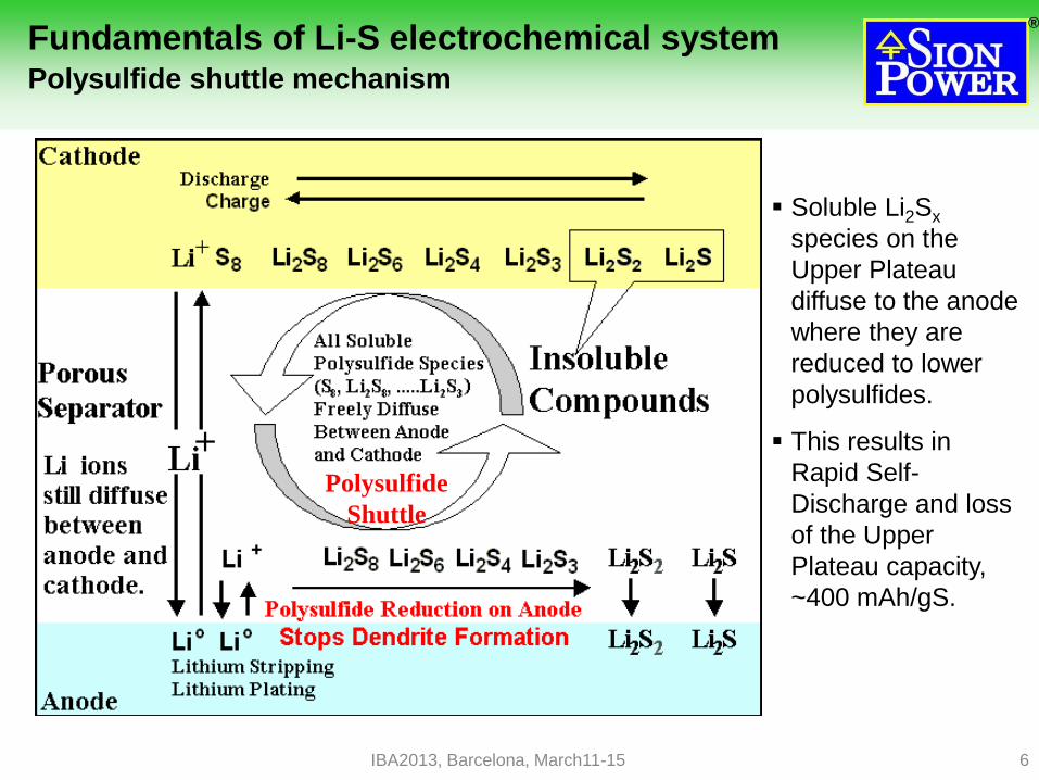
Fundamentals of Li-S electrochemical system Polysulfide shuttle mechanism
Soluble Li2Sx
species on the
Upper Plateau
diffuse to the anode
where they are
reduced to lower
polysulfides.
This results in
Rapid Self-
Discharge and loss
of the Upper
Plateau capacity,
~400 mAh/gS.
Polysulfide
Shuttle
IBA2013, Barcelona, March11-15

®
7
Typical charge (C/8) and discharge (C/5)
profiles with strong shuttle.
NOX compounds chemically protect Li anode, suppress the
shuttle, restore Li-S cell capacity and allow charge control
at 99.8% efficiency
IBA2013, Barcelona, March11-15
Typical charge (C/8) and discharge (C/5)
for cells containing Nitrate.
Sion’s shuttle inhibitors permit near 100% utilization of the high voltage
plateau sulfur and up to 75% of total sulfur utilization at C/10 - C/5 rates.
1.7
1.9
2.1
2.3
2.5
0.0 0.2 0.4 0.6 0.8 1.0 1.2 1.4V
olt
ag
e
Specific Capacity, Ah/g
First Discharge
All Recharges
Subsequent Discharges
1.7
1.9
2.1
2.3
2.5
0.0 0.2 0.4 0.6 0.8 1.0 1.2 1.4
Vo
ltag
e
Specific Capacity, Ah/g
First Discharge
All Recharges
Subsequent Discharges
®
8
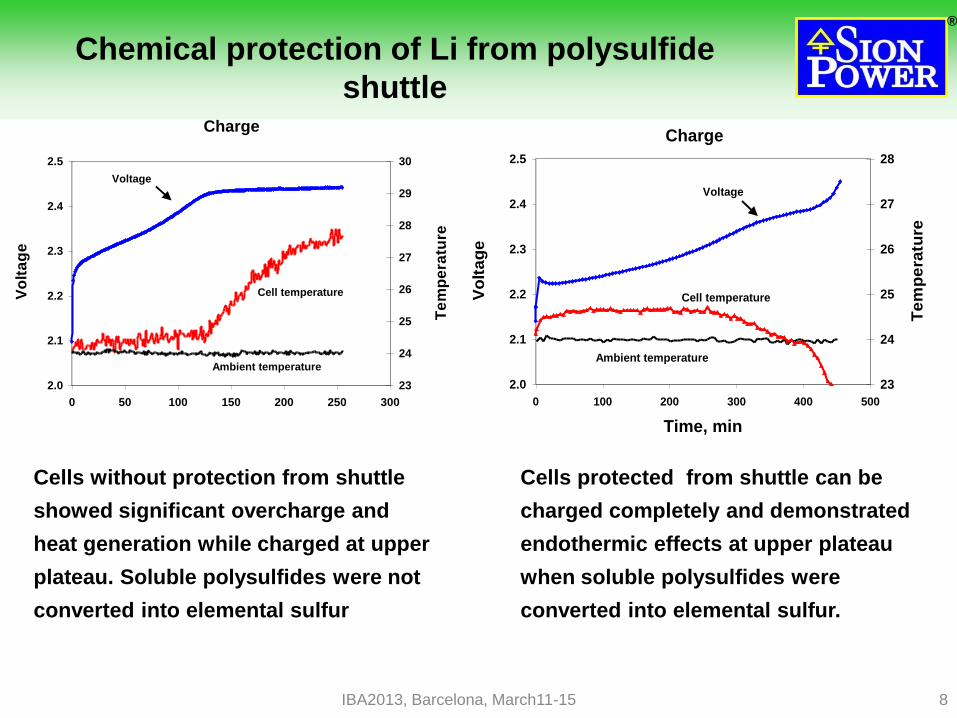
Chemical protection of Li from polysulfide
shuttle
Charge
2.0
2.1
2.2
2.3
2.4
2.5
0 100 200 300 400 500
Time, min
Vo
lta
ge
23
24
25
26
27
28
Te
mp
era
ture
Ambient temperature
Cell temperature
Voltage
Charge
2.0
2.1
2.2
2.3
2.4
2.5
0 50 100 150 200 250 300
Vo
lta
ge
23
24
25
26
27
28
29
30
Te
mp
era
ture
Ambient temperature
Cell temperature
Voltage
Cells without protection from shuttle
showed significant overcharge and
heat generation while charged at upper
plateau. Soluble polysulfides were not
converted into elemental sulfur
Cells protected from shuttle can be
charged completely and demonstrated
endothermic effects at upper plateau
when soluble polysulfides were
converted into elemental sulfur.
IBA2013, Barcelona, March11-15

®
9
Current status of 350 Wh/kg Sion Power cells
with chemically protected Li anode
IBA2013, Barcelona, March11-15
Wound Prismatic
37mm x 55mm x 11mm
17 grams
350 Wh/kg
320 Wh/l
-20°C to + 45°C operating
temp.
30 to 60 cycles @ 100%
DOD
25 mΩ impedance

®
10
First Commercial Li-S Application is
Unmanned Aerial Vehicles - UAVs
Flew to >70,000 ft where temperature is < -60oC.
QinetiQ's Zephyr 7 UAV Captures World Record for
Longest Duration Flight (unmanned or otherwise).
23 meter Wing Span
July, 2010
Used solar power to fly & recharge batteries by day.
New World Record: >14 days of continuous flight.
Flight was powered by Sion Li-S batteries at night.
IBA2013, Barcelona, March11-15
®
11
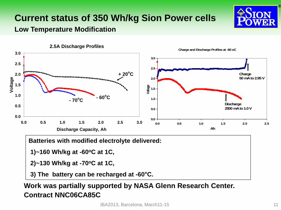
Charge and Discharge Profiles at -60 oC
0.0
0.5
1.0
1.5
2.0
2.5
3.0
0.0 0.5 1.0 1.5 2.0 2.5
Ah
Vol
tage
Charge
50 mA to 2.95 V
Discharge
2500 mA to 1.0 V
Batteries with modified electrolyte delivered:
1)~160 Wh/kg at -60oC at 1C,
2)~130 Wh/kg at -70oC at 1C,
3) The battery can be recharged at -60°C.
2.5A Discharge Profiles
0.0
0.5
1.0
1.5
2.0
2.5
3.0
0.0 0.5 1.0 1.5 2.0 2.5 3.0
Discharge Capacity, Ah
Vo
lta
ge
- 70oC
- 60oC
+ 20oC
Current status of 350 Wh/kg Sion Power cells Low Temperature Modification
Work was partially supported by NASA Glenn Research Center.
Contract NNC06CA85C
IBA2013, Barcelona, March11-15
®
12
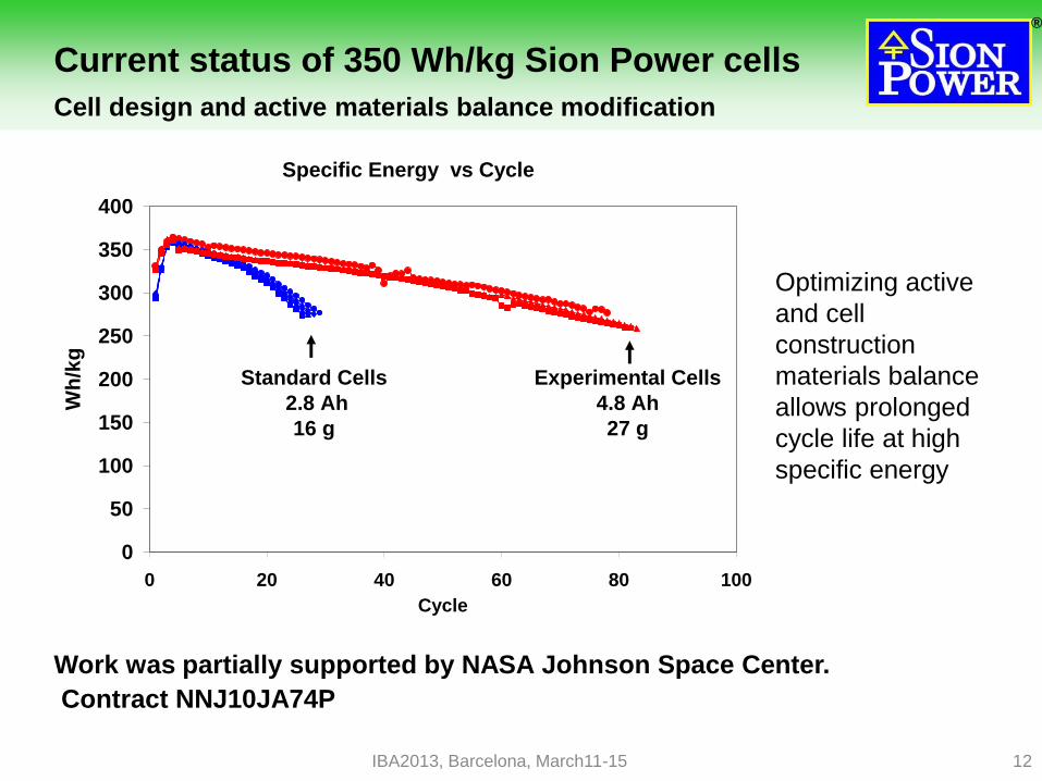
Current status of 350 Wh/kg Sion Power cells
Cell design and active materials balance modification
Specific Energy vs Cycle
0
50
100
150
200
250
300
350
400
0 20 40 60 80 100
Cycle
Wh
/kg
Standard Cells
2.8 Ah
16 g
Experimental Cells
4.8 Ah
27 g
Work was partially supported by NASA Johnson Space Center.
Contract NNJ10JA74P
IBA2013, Barcelona, March11-15
Optimizing active
and cell
construction
materials balance
allows prolonged
cycle life at high
specific energy
®
13
0
1000
2000
3000
4000
0% 20% 40% 60% 80% 100%
Cell DoD
Sp
ecif
ic P
ow
er,
W/k
g
30 A
20 A
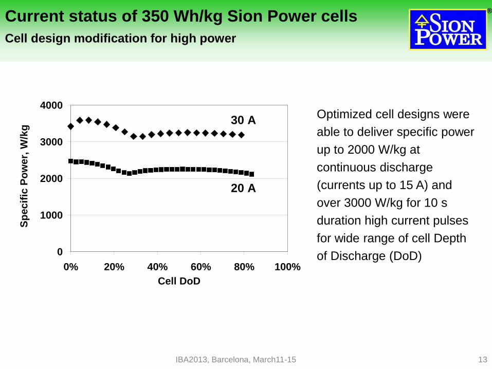
Current status of 350 Wh/kg Sion Power cells
Cell design modification for high power
Optimized cell designs were
able to deliver specific power
up to 2000 W/kg at
continuous discharge
(currents up to 15 A) and
over 3000 W/kg for 10 s
duration high current pulses
for wide range of cell Depth
of Discharge (DoD)
IBA2013, Barcelona, March11-15
®
14
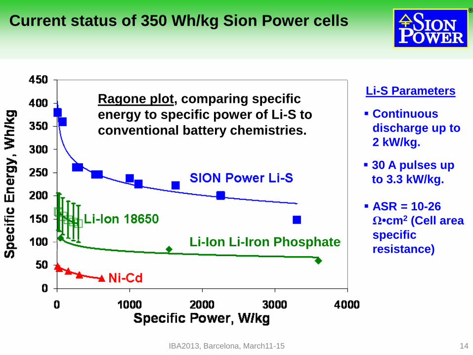
Current status of 350 Wh/kg Sion Power cells
Ragone plot, comparing specific
energy to specific power of Li-S to
conventional battery chemistries.
Li-Ion Li-Iron Phosphate
Continuous
discharge up to
2 kW/kg.
30 A pulses up
to 3.3 kW/kg.
ASR = 10-26
Ω•cm2 (Cell area
specific
resistance)
Li-S Parameters
IBA2013, Barcelona, March11-15

®
15
Addressing Remaining Challenges Keys to the EV Market for Lithium-Sulfur
Cycle life of Li-S cells with chemically protected Li anode is
limited to ~ 100 cycles for 350 Wh/kg and higher specific
energies designs.
Elevated temperature stability/safety is limited to ~ 150 oC
Causes of the problems:
Development of rough lithium morphology affecting cycle
life and safety.
Lithium/Electrolyte depletion affecting cycle life and
capacity through cathode clogging.
Lithium reaction with sulfur and polysulfides affecting
thermal stability/safety.
IBA2013, Barcelona, March11-15

®
16
Lithium/Electrolyte depletion
Specific Energy-Cycle Life relationship for Sion Power experimental
cells
IBA2013, Barcelona, March11-15
0
100
200
300
400
500
600
1 10 100 1000
Sp
ec
ific
En
erg
y,
Wh
/kg
Cycle Life to 80%
With excessive
amounts of electrolyte
and lithium cycle life
can exceed 500
cycles at 150 Wh/kg.
Reduced amounts of
electrolyte and Li lead
to 500 Wh/kg at the
expense of cycle life.
The key for success
is stopping electrolyte
and Li depletion.

®
17
O O
O OLi
MeOLi
O
CH4
MeSxLi
Li/Li2Sx
O O
O OLi
Li/Li2Sx
H2
RO
O OLi
n
High amount, highly soluble and highly
detrimental for S cathode performance.
Moderate amount, low solubility, neutral.
Small amount, soluble, consumes S.
Traces.
Traces.
Increases anode polarization
Traces
Highly soluble and highly detrimental
for S cathode performance.
Identified at Sion Power
Identified at Sion Power and by D. Aurbach, J. Electrochem. Soc.156,8. 2009.
1,2-Dimethoxyethane
Identified depletion products and their impact on battery performance.
The Chemistry of Electrolyte Solvent Depletion
1,3-Dioxolane
IBA2013, Barcelona, March11-15

®
18
Sion Power approach for next
generation Li-S technology
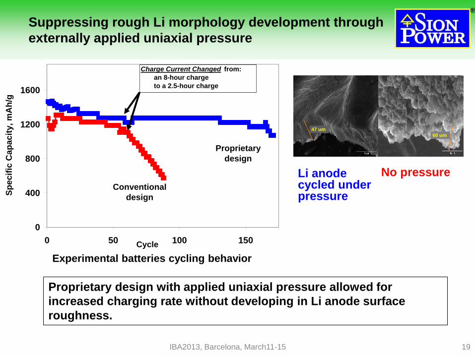
Suppressing rough Li morphology development through
externally applied uniaxial pressure
Physical protection of lithium with multi-functional
membrane assemblies:
– Multi-layer solid electrolyte ceramic/polymer coating
– Gel electrolyte
– Dual-phase electrolyte
Optimize cathode structure and porosity to limit pore
blocking and increase sulfur specific capacity
IBA2013, Barcelona, March11-15
®
19
47 um
60 um
No pressure Li anode cycled under pressure
Suppressing rough Li morphology development through
externally applied uniaxial pressure
Proprietary design with applied uniaxial pressure allowed for
increased charging rate without developing in Li anode surface
roughness.
0
400
800
1200
1600
0 50 100 150Cycle
Sp
ec
ific
Ca
pa
cit
y, m
Ah
/g
Conventional
design
Proprietary
design
Charge Current Changed from:
an 8-hour charge
to a 2.5-hour charge
Experimental batteries cycling behavior
IBA2013, Barcelona, March11-15

®
20
Sion Power BASF approach for
next generation Li-S technology
Physically Protected Li Anode
Work is partially supported by USA Department of Energy. Contract DE-AR0000067
IBA2013, Barcelona, March11-15
Gel-Electrolyte Polymer layer
Protective layer
Vacuum Deposited Lithium
After cycling at C/5
SEM image of Protected Li Anode
cross-section after cycling in the
electrochemical cell
Working electrode
surface
Back-side electrode
surface

®
21
Dual Phase Electrolyte Li-S Battery “Anode” Liquid 1:
• Immobilized within polymeric gel applied to anode.
• Stable with lithium preventing side reactions and dendrite growth.
• Immiscible with Phase 2 electrolyte and does not dissolve polysulfides.
• Polymeric gel can serve as coated separator.
“Cathode” Liquid 2:
• Tailored to improve high energy Sion Power sulfur cathode performance.
• Immiscible with Phase 1 electrolyte.
• High ion conductivity and lithium polysulfide solubility.
Sion Power approach for next
generation Li-S technology
Work is partially supported by USA Department of Energy. Contract DE-EE0001997
IBA2013, Barcelona, March11-15
Li Anode Lio
Gel-Polymer Li +
No Li2Sx Solubility with
Liquid 1 Li +
Li +
Porous
Carbon-Sulfur
Cathode
with Liquid 2
Charge
Discharge
S8 Li2S8 Li2S6 Li2S4 Li2S3 Li2S2 Li2S
®
22
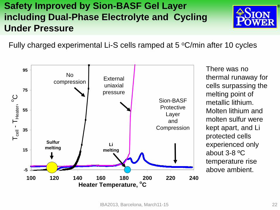
Safety Improved by Sion-BASF Gel Layer
including Dual-Phase Electrolyte and Cycling
Under Pressure
Fully charged experimental Li-S cells ramped at 5 oC/min after 10 cycles
-5
15
35
55
75
95
100 120 140 160 180 200 220 240
Heater Temperature, oC
Tcell
- T
Heate
r, o
C
Sulfur
meltingLi
melting
No
compressionExternal
uniaxial
pressure
Sion-BASF
Protective
Layer
and
Compression
There was no
thermal runaway for
cells surpassing the
melting point of
metallic lithium.
Molten lithium and
molten sulfur were
kept apart, and Li
protected cells
experienced only
about 3-8 ºC
temperature rise
above ambient.
IBA2013, Barcelona, March11-15

®
23
Progress on cathode structure
Improved pore
structure provides
cathode functioning
under pressure
without pores
clogging and with
increased sulfur
utilization.
This development paves the way to increasing specific energy from the
current 350 Wh/kg to the 550 Wh/kg needed to achieve a 500 km EV range
IBA2013, Barcelona, March11-15
0
400
800
1200
1600
0 2000 4000 6000 8000
Sp
ec
ific
Ca
pa
cit
y, m
Ah
/g
Specific Discharge Rate, mA/g S
C/30
C/3
10C
1C
2C 4C
®
24
Next Generation Li-S Technology
Sion Power is moving to the next generation with new
anode and cathode materials to enable a quantum leap
in performance.
Sion’s breakthrough anode protection technology will
enable higher energy densities and safety than
previously possible.
– Already demonstrated techniques in the laboratory that extend
cycle life while inhibiting thermal runaway in Li-S cells.
Manufacturing technology utilizes standard methods for
cell and battery assembly.
Volume cost for Sion’s Li-S battery is expected to meet
or beat long term cost targets for EV commercialization.
24
®
25
Sion Power Partners in Development
January 12, 2012 – BASF announced that it has invested
$50 million to acquire an equity ownership position in
privately held Sion Power, the global leader in the
development of lithium-sulfur (Li-S) batteries, based in
Tucson, Arizona.
This equity partnership expands upon an existing joint
development agreement that BASF Future Business
GmbH established with Sion Power in 2009 to accelerate
the commercialization of Sion’s proprietary Li-S battery
technology for electric and plug-in electric vehicles and
other high-energy applications over the next decade.
25 IBA2013, Barcelona, March11-15
®
26
Sion Power Corporation, in collaboration with
BASF, is very optimistic that the future of all
EV applications will be dominated by Sion
Power’s lithium-sulfur technology.
Takeaway
IBA2013, Barcelona, March11-15