Embed Size (px)
Citation preview

HIGH FUNCTION&
LOW ACOUSTIC NOISE
FR-A500
TRANSISTORIZED INVERTER
– INSTRUCTION MANUAL –
FR-A520-0.4K to 55K(-NA)FR-A540-0.4K to 55K(-NA)(-EC)

A - 1
Thank you for choosing this Mitsubishi transistorized Inverter.
This instruction manual gives handling information and precautions for use of this
equipment.
Incorrect handling might cause an unexpected fault. Before using the inverter, please read
this manual carefully to use the equipment to its optimum.
Please forward this manual to the end user.
This section is specifically about safety matters
Do not attempt to install, operate, maintain or inspect the inverter until you have read through thisinstruction manual and appended documents carefully and can use the equipment correctly.Do not use the inverter until you have a full knowledge of the equipment, safety information andinstructions.In this instruction manual, the safety instruction levels are classified into “WARNING” and “CAUTION”.
Assumes that incorrect handling may cause hazardous conditions, resulting indeath or severe injury.
Assumes that incorrect handling may cause hazardous conditions, resulting inmedium or slight injury, or may cause physical damage only.
Note that the CAUTION level may lead to a serious consequence according to conditions. Please followthe instructions of both levels because they are important to personnel safety.
CAUTION
WARNING
A - 2
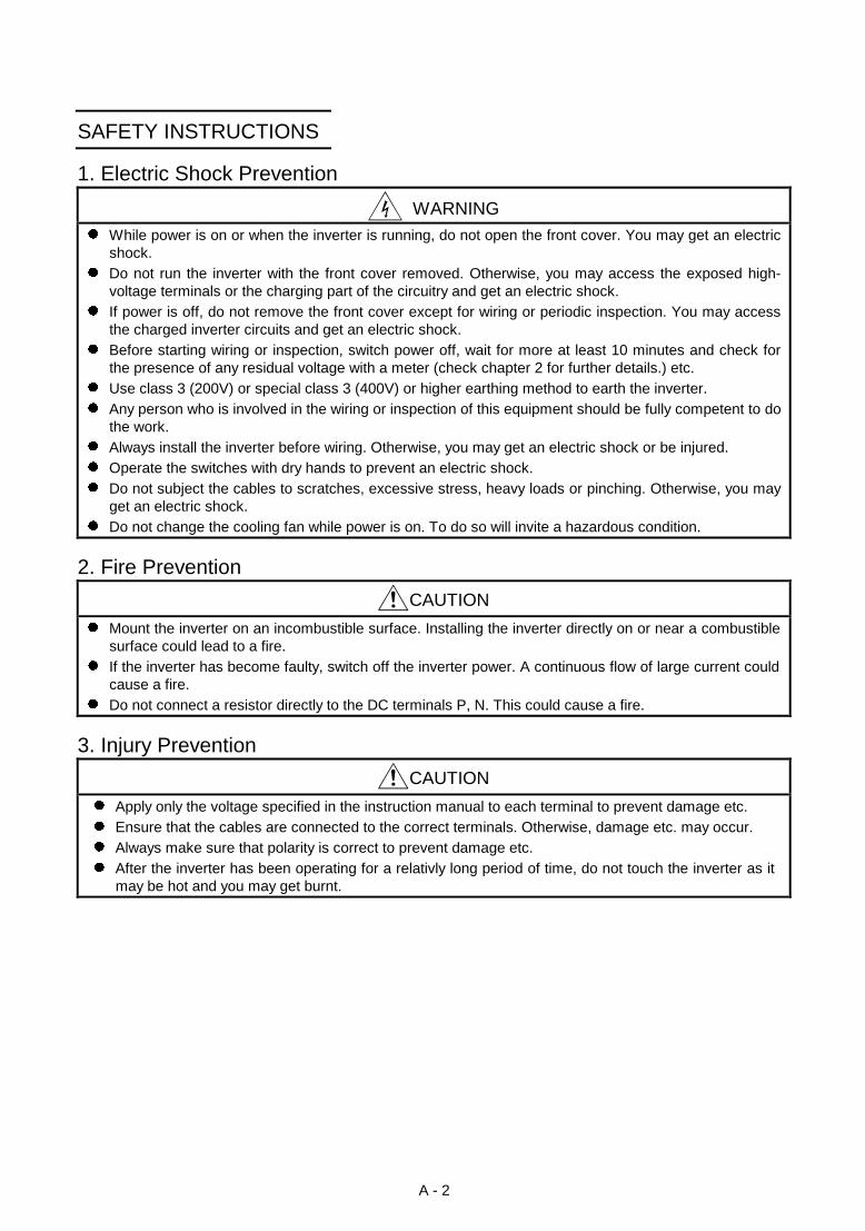
SAFETY INSTRUCTIONS
1. Electric Shock Prevention
WARNINGz While power is on or when the inverter is running, do not open the front cover. You may get an electric
shock.z Do not run the inverter with the front cover removed. Otherwise, you may access the exposed high-
voltage terminals or the charging part of the circuitry and get an electric shock.z If power is off, do not remove the front cover except for wiring or periodic inspection. You may access
the charged inverter circuits and get an electric shock.z Before starting wiring or inspection, switch power off, wait for more at least 10 minutes and check for
the presence of any residual voltage with a meter (check chapter 2 for further details.) etc.z Use class 3 (200V) or special class 3 (400V) or higher earthing method to earth the inverter.z Any person who is involved in the wiring or inspection of this equipment should be fully competent to do
the work.z Always install the inverter before wiring. Otherwise, you may get an electric shock or be injured.z Operate the switches with dry hands to prevent an electric shock.z Do not subject the cables to scratches, excessive stress, heavy loads or pinching. Otherwise, you may
get an electric shock.z Do not change the cooling fan while power is on. To do so will invite a hazardous condition.
2. Fire Prevention
CAUTION
z Mount the inverter on an incombustible surface. Installing the inverter directly on or near a combustiblesurface could lead to a fire.
z If the inverter has become faulty, switch off the inverter power. A continuous flow of large current couldcause a fire.
z Do not connect a resistor directly to the DC terminals P, N. This could cause a fire.
3. Injury Prevention
CAUTION
z Apply only the voltage specified in the instruction manual to each terminal to prevent damage etc.z Ensure that the cables are connected to the correct terminals. Otherwise, damage etc. may occur.z Always make sure that polarity is correct to prevent damage etc.z After the inverter has been operating for a relativly long period of time, do not touch the inverter as it
may be hot and you may get burnt.

A - 3
4. Additional instructionsAlso note the following points to prevent an accidental failure, injury, electric shock, etc.:
(1) Transportation and installation
CAUTION
z When carrying products, use correct lifting gear to prevent injury.z Do not stack the inverter boxes higher than the number recommended.z Ensure that installation position and material can withstand the weight of the inverter. Install
according to the information in the Instruction Manual.z Do not operate if the inverter is damaged or has parts missing.z Do not hold the inverter by the front cover; it may fall off.z Do not stand or rest heavy objects on the inverter.z Check the inverter mounting orientation is correct.z Prevent screws, wire fragments, conductive bodies, oil or other flammable substances from entering
the inverter.z Do not drop the inverter, or subject it to impact.z Use the inverter under the following environmental conditions:
Ambient temperature
Constant torque: -10°C to +50°C (14°F to 122°F) (non-freezing)(-10°C to +40°C with FR-A5CV attachment)
Variable torque: -10°C to +40°C (14°F to 104°F) (non-freezing)(-10°C to +30°C with FR-A5CV attachment)
Ambient humidity 90%RH or less (non-condensing)Storage temperature -20°C to +65°C* (-4°F to 149°F)Ambience Indoors (free from corrosive gas, flammable gas, oil mist, dust and dirt)E
nviro
nmen
t
Altitude, vibrationMaximum 1000m (3280.80 feet.) above sea level for standard operation.After that derate by 3% for every extra 500m up to 2500m (91%).
•• *Temperatures applicable for a short time, e.g. in transit.
(2) Wiring
CAUTION
z Do not fit capacitive equipment such as a power factor correction capacitor, noise filter or surgesuppressor to the output of the inverter.
z The connection orientation of the output cables U, V, W to the motor will affect the direction ofrotation of the motor.
(3) Trial run
CAUTION
z Check all parameters, and ensure that the machine will not be damaged by a sudden start-up.
(4) Operation
CAUTION
z When you have chosen the retry function, stay away from the equipment as it will restart suddenlyafter an alarm stop.
z The [STOP] key is valid only when the appropriate function setting has been made. Prepare anemergency stop switch separately.
z Make sure that the start signal is off before resetting the inverter alarm. A failure to do so may restartthe motor suddenly.

A - 4
CAUTION
z The load used should be a three-phase induction motor only. Connection of any other electricalequipment to the inverter output may damage the equipment.
z The electronic overcurrent protection does not guarantee protection of the motor from overheating.z Do not use a magnetic contactor on the inverter input for frequent starting/stopping of the inverter.z Use a noise filter to reduce the effect of electromagnetic interference. Otherwise nearby electronic
equipment may be affected.z Take measures to suppress harmonics. Otherwise power harmonics from the inverter may
heat/damage the power capacitor and generator.z When a 400V class motor is inverter-driven, it should be insulation-enhanced or surge voltages
suppressed. Surge voltages attributable to the wiring constants may occur at the motor terminals,deteriorating the insulation of the motor.
z When parameter clear or all clear is performed, each parameter returns to the factory setting. Re-setthe required parameters before starting operation.
z The inverter can be easily set for high-speed operation. Before changing its setting, examine theperformance of the motor and machine.
z In addition to the inverter's holding function, install a holding device to ensure safety.z Before running an inverter which had been stored for a long period, always perform inspection and
test operation.
(5) Emergency stop
CAUTION
z Provide a safety backup such as an emergency brake which will prevent the machine and equipmentfrom hazardous conditions if the inverter fails.
(6) Maintenance, inspection and parts replacement
CAUTION
z Do not carry out a megger (insulation resistance) test on the control circuit of the inverter.
(7) Disposing of the inverter
CAUTION
z Treat as industrial waste.
(8) General instructions
Many of the diagrams and drawings in this instruction manual show the inverter without a cover, or partially
open. Never run the inverter like this. Always replace the cover and follow this instruction manual when
operating the inverter.

CONTENTS
I
287/,1(
1.1 Pre-Operation Information .........................................................................................................................................1
1.1.1 Precautions for operation....................................................................................................................................1
1.2 Basic Configuration....................................................................................................................................................2
1.2.1 Basic configuration .............................................................................................................................................2
1.3 Structure ....................................................................................................................................................................3
1.3.1 Appearance and structure ..................................................................................................................................3
1.3.2 Removal and reinstallation of the front cover ............................................................................. ........................4
1.3.3 Removal and reinstallation of the operation panel......................................................................... .....................6
,167$//$7,21 $1' :,5,1*
2.1 Installation..................................................................................................................................................................7
2.1.1 Instructions for installation ..................................................................................................................................7
2.2 Wiring ........................................................................................................................................................................9
2.2.1 Terminal connection diagram .............................................................................................................................9
2.2.2 Wiring of the main circuit ..................................................................................................................................12
2.2.3 Wiring of the control circuit ...............................................................................................................................18
2.2.4 Connection to the PU connector.......................................................................................................................22
2.2.5 Connection of stand-alone option units .................................................................................... ........................24
2.2.6 Design information............................................................................................................................................28
2.3 Other wiring .............................................................................................................................................................29
2.3.1 Power harmonics ..............................................................................................................................................29
2.3.2 Japanese harmonic suppression guidelines.................................................................................. ...................30
2.3.3 Inverter-generated noises and reduction techniques........................................................................ ................33
2.3.4 Leakage currents and countermeasures ...................................................................................... ....................37
2.3.5 Inverter-driven 400V class motor ......................................................................................................................38
2.3.6 Peripheral devices ............................................................................................................................................39
2.3.7 Instructions for compliance with the UL and CSA standards................................................................. ...........41
2.3.8 Instructions for compliance with the European standards ................................................................... .............42
2.3.9 Earthing (EC version)........................................................................................................................................43
23(5$7,21
3.1 Pre-Operation Information .......................................................................................................................................45
3.1.1 Devices and parts to be prepared for operation ............................................................................ ...................45
3.1.2 Power on...........................................................................................................................................................47
3.1.3 Parameter check...............................................................................................................................................47
3.2 Operation .................................................................................................................................................................53
3.2.1 Pre-operation checks........................................................................................................................................53
3.2.2 External operation mode (Operation using external input signals) .......................................................... .........54
3.2.3 PU operation mode (Operation using the operation panel (FR-DU04))........................................................ ...55
3.2.4 Combined operation mode (Operation using the external input signals and PU) ............................................56
3$5$0(7(5
4.1 Parameter List .........................................................................................................................................................57
4.2 Parameter Function Details .....................................................................................................................................63
z Torque boost (Pr. 0, Pr. 46, Pr. 112) .......................................................................................................................63
z Output frequency range (Pr. 1, Pr. 2, Pr. 18) ..........................................................................................................64

II
z Base frequency, base frequency voltage (Pr. 3, Pr. 19, Pr. 47, Pr. 113).................................................................65
z Multi-speed operation (Pr. 4 to Pr. 6, Pr. 24 to Pr. 27, Pr. 232 to Pr. 239) ..............................................................66
z Acceleration/deceleration time (Pr. 7, Pr. 8, Pr. 20, Pr. 21, Pr. 44, Pr. 45, Pr. 110, Pr. 111) ..................................67
z Electronic overcurrent protection (Pr. 9)..................................................................................................................68
z DC dynamic brake (Pr. 10, Pr. 11, Pr. 12)...............................................................................................................69
z Starting frequency (Pr. 13) ......................................................................................................................................70
z Load pattern selection (Pr. 14) ................................................................................................................................70
z Jog operation (Pr. 15, Pr. 16) ..................................................................................................................................71
z MRS input selection (Pr. 17) ...................................................................................................................................72
z Stall prevention (Pr. 22, Pr. 23, Pr. 66, Pr. 148, Pr. 149, Pr. 154)...........................................................................73
z Multi-speed input compensation (Pr. 28).................................................................................................................74
z Acceleration/deceleration pattern (Pr. 29, Pr. 140 to Pr. 143).................................................................................75
z Regenerative brake duty (Pr. 30, Pr. 70).................................................................................................................76
z Frequency jump (Pr. 31 to Pr. 36) ...........................................................................................................................77
z Speed display (Pr. 37, Pr. 144) ...............................................................................................................................78
z Up-to-frequency sensitivity (Pr. 41) .........................................................................................................................79
z Output frequency detection (Pr. 42, Pr. 43, Pr. 50, Pr. 116) ...................................................................................79
z Second/third stall prevention (Pr. 48, Pr. 49, Pr. 114, Pr. 115) ...............................................................................80
z Monitor display/FM, AM terminal function selection (Pr. 52 to Pr. 54, Pr. 158) ................................................ .......82
z Monitoring reference (Pr. 55, Pr. 56).......................................................................................................................84
z Automatic restart after instantaneous power failure (Pr. 57, Pr. 58, Pr. 162 to Pr. 165) ...................................... ...85
z Remote setting function selection (Pr. 59) ..............................................................................................................87
z Intelligent mode selection (Pr. 60)...........................................................................................................................88
z Acceleration/deceleration reference current/lift mode starting frequency (Pr. 61 to Pr. 64)................................... .90
z Retry function (Pr. 65, Pr. 67 to Pr. 69) ...................................................................................................................91
z Applied motor (Pr. 71) .............................................................................................................................................93
z PWM carrier frequency (Pr. 72, Pr. 240) .................................................................................................................94
z Voltage input (Pr. 73) ..............................................................................................................................................95
z Input filter time constant (Pr. 74) .............................................................................................................................96
z Reset selection/PU disconnection detection/PU stop selection (Pr. 75) ......................................................... ........96
z Alarm code output selection (Pr. 76) .......................................................................................................................98
z Parameter write inhibit selection (Pr. 77) ................................................................................................................99
z Reverse rotation prevention selection (Pr. 78) ......................................................................................................100
z Operation mode selection (Pr. 79) ........................................................................................................................101
z Motor capacity/number of motor poles/speed control gain (Pr. 80, Pr. 81, Pr. 89) .............................................. .104
z Offline auto tuning function (Pr. 82 to Pr. 84, Pr. 90 to Pr. 94, Pr. 96) ..................................................................105
z Online auto tuning selection (Pr. 95) .....................................................................................................................111
z V/F control frequency (voltage) (Pr. 100 to Pr. 109)..............................................................................................113
z Computer link operation (Pr. 117 to Pr. 124).........................................................................................................114
z PID control (Pr. 128 to Pr. 134) .............................................................................................................................124
z Commercial power supply-inverter switch-over function (Pr. 135 to Pr. 139).................................................... ....131
z Output current detection function (Pr. 150, Pr. 151)..............................................................................................135
z Zero current detection (Pr. 152, Pr. 153)...............................................................................................................136
z RT signal activated condition selection (Pr. 155) ............................................................................. .....................137
z Stall prevention function and current limit function (Pr. 156)................................................................ .................137
z OL signal output timer (Pr. 157) ............................................................................................................................139
z User group selection (Pr. 160, Pr. 173 to Pr. 176) ................................................................................................140
z Watt-hour meter clear/actual operation hour meter clear (Pr. 170, Pr. 171) .................................................... .....141
z Input terminal function selection (Pr. 180 to Pr. 186) ........................................................................ ....................141
z Output terminal function selection (Pr. 190 to Pr. 195) ....................................................................... ..................144

III
z User initial value setting (Pr. 199) .........................................................................................................................146
z Programmed operation function (Pr. 200 to Pr. 231) ............................................................................................147
z Cooling fan operation selection (Pr. 244)..............................................................................................................151
z Stop selection (Pr. 250).........................................................................................................................................152
z Power failure-time deceleration-to-stop function (Pr. 261 to Pr. 266) ......................................................... ..........154
z Stop-on-contact, load torque high-speed frequency selection (Pr. 270) ......................................................... ......156
z High-speed frequency control (Pr. 271 to Pr. 274)................................................................................................157
z Stop on contact (Pr. 275, Pr. 276).........................................................................................................................161
z Brake sequence function (Pr. 278 to Pr. 285) .......................................................................................................164
z Droop control (Pr. 286, Pr. 287) ............................................................................................................................168
z Meter (frequency meter) calibration (Pr. 900, Pr. 901)..........................................................................................169
z Frequency setting voltage (current) bias and gain (Pr. 902 to Pr. 905)........................................................ .........171
z Buzzer control (Pr. 990) ........................................................................................................................................173
3527(&7,9( )81&7,216
5.1 Errors (alarms).......................................................................................................................................................174
5.1.1 Error (alarm) definitions ..................................................................................................................................174
5.1.2 Correspondences between digital and actual characters ..................................................................... ..........177
5.1.3 Alarm code output...........................................................................................................................................178
5.1.4 Resetting the inverter......................................................................................................................................178
5.2 Troubleshooting .....................................................................................................................................................179
5.2.1 Checking the operation panel display at alarm stop ........................................................................ ...............179
5.2.2 Faults and check points ..................................................................................................................................180
5.3 Precautions for Maintenance and Inspection................................................................................. ........................182
5.3.1 Precautions for maintenance and inspection................................................................................ ..................182
5.3.2 Check items ....................................................................................................................................................182
5.3.3 Periodic inspection..........................................................................................................................................182
5.3.4 Insulation resistance test using megger ................................................................................... ......................183
5.3.5 Pressure test...................................................................................................................................................183
5.3.6 Replacement of parts......................................................................................................................................186
5.3.7 Inverter replacement.......................................................................................................................................187
5.3.8 Measurement of main circuit voltages, currents and power.................................................................. ..........188
63(&,),&$7,216
6.1 Standard Specifications .........................................................................................................................................190
6.1.1 Model specifications .......................................................................................................................................190
6.1.2 Common specifications...................................................................................................................................192
6.1.3 Outline drawings .............................................................................................................................................194
237,216
7.1 Option List..............................................................................................................................................................198
7.1.1 Stand-alone options........................................................................................................................................198
7.1.2 Inboard dedicated options ..............................................................................................................................200
$33(1',&(6
Appendix 1 Data Code List ..........................................................................................................................................201
Appendix 2 List of Parameters Classified by Purposes of Use.................................................................... ................207
Appendix 3 Operating the Inverter Using a Single-Phase Power Supply ............................................................ ........208
1
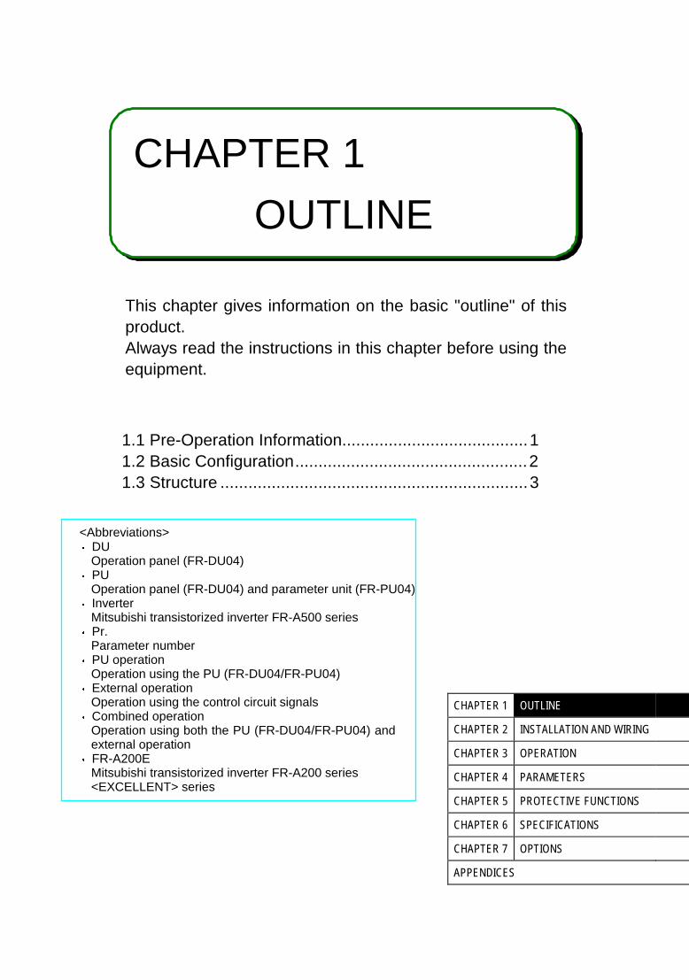
CHAPTER 1
OUTLINE
This chapter gives information on the basic "outline" of thisproduct.Always read the instructions in this chapter before using theequipment.
1.1 Pre-Operation Information........................................1 1.2 Basic Configuration..................................................2 1.3 Structure ..................................................................3
<Abbreviations>y DU
Operation panel (FR-DU04)y PU
Operation panel (FR-DU04) and parameter unit (FR-PU04)y Inverter
Mitsubishi transistorized inverter FR-A500 seriesy Pr.
Parameter numbery PU operation
Operation using the PU (FR-DU04/FR-PU04)y External operation
Operation using the control circuit signalsy Combined operation
Operation using both the PU (FR-DU04/FR-PU04) andexternal operation
y FR-A200EMitsubishi transistorized inverter FR-A200 series<EXCELLENT> series
CHAPTER 1 OUTLINE
CHAPTER 2 INSTALLATION AND WIRING
CHAPTER 3 OPERATION
CHAPTER 4 PARAMETERS
CHAPTER 5 PROTECTIVE FUNCTIONS
CHAPTER 6 SPECIFICATIONS
CHAPTER 7 OPTIONS
APPENDICES

1.1 Pre-Operation InformationOUTLINE
1
1 OUTLINE1.1 Pre-Operation Information
1.1.1 Precautions for operation
Incorrect handling might cause the inverter to operate improperly, its life to be reduced considerably, or at theworst, the inverter to be damaged. Handle the inverter properly in accordance with the information in eachsection as well as the precautions and instructions of this manual to use it correctly.This manual is written for the FR-A500 series transistorized inverters.For handling information on the parameter unit (FR-PU04), inboard options, stand-alone options, etc., refer tothe corresponding manuals.
(1) Unpacking and product check
Unpack the inverter and check the capacity plate on the front cover and the rating plate on the inverter sideface to ensure that the product agrees with your order and the inverter is intact.
1) Inverter type
FR-A520-0.4K/
MITSUBISHIMODEL
FR-A520-0.4KINVERTER
POWER
INPUT
OUTPUT
SERIAL
MITSUBISHI ELECTRIC CORPORATION
0.4kW
XXXXX
MADE IN JAPAN
XXXXX
Capacity plate
Inverter type Serial number
Capacity plateRating plate
Rating plate
Input rating
Output rating
Serial number
Inverter type
FR- A520 - 0.4K -
Symbol Voltage ClassA520A540
200V class400V class
Symbol Applicable Motor Capacity0.4K to 55K Indicates capacity in "kW".
Symbol SpecificationsNoneNA
Japanese specificationsU.S. specifications
EC European specifications
Applicable motorcapacity
2) AccessoryInstruction manual
If you have found any discrepancy, damage, etc., please contact your sales representative.
(2) Preparations of instruments and parts required for operation
Instruments and parts to be prepared depend on how the inverter is operated. Prepare equipment and partsas necessary. (Refer to page 45.)
(3) Installation
To operate the inverter with high performance for a long time, install the inverter in a proper place, in thecorrect direction, and with proper clearances. (Refer to page 7.)
(4) Wiring
Connect the power supply, motor and operation signals (control signals) to the terminal block. Note thatincorrect connection may damage the inverter and peripheral devices. (See page 12.)
1.2 Basic ConfigurationOUTLINE
2
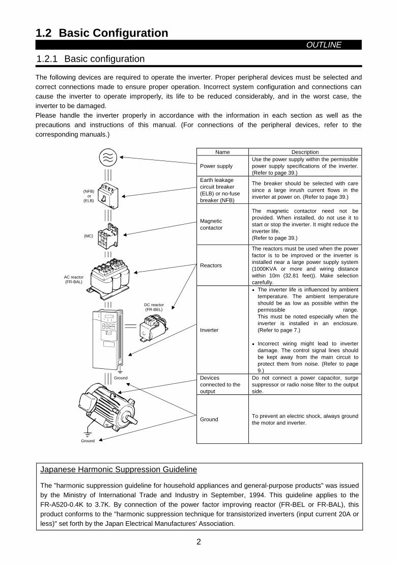
1.2 Basic Configuration
1.2.1 Basic configuration
The following devices are required to operate the inverter. Proper peripheral devices must be selected andcorrect connections made to ensure proper operation. Incorrect system configuration and connections cancause the inverter to operate improperly, its life to be reduced considerably, and in the worst case, theinverter to be damaged.Please handle the inverter properly in accordance with the information in each section as well as theprecautions and instructions of this manual. (For connections of the peripheral devices, refer to thecorresponding manuals.)
Name Description
Power supplyUse the power supply within the permissiblepower supply specifications of the inverter.(Refer to page 39.)
Earth leakagecircuit breaker(ELB) or no-fusebreaker (NFB)
The breaker should be selected with caresince a large inrush current flows in theinverter at power on. (Refer to page 39.)
Magneticcontactor
The magnetic contactor need not beprovided. When installed, do not use it tostart or stop the inverter. It might reduce theinverter life.(Refer to page 39.)
Reactors
The reactors must be used when the powerfactor is to be improved or the inverter isinstalled near a large power supply system(1000KVA or more and wiring distancewithin 10m (32.81 feet)). Make selectioncarefully.
Inverter
z The inverter life is influenced by ambienttemperature. The ambient temperatureshould be as low as possible within thepermissible range.This must be noted especially when theinverter is installed in an enclosure.(Refer to page 7.)
z Incorrect wiring might lead to inverterdamage. The control signal lines shouldbe kept away from the main circuit toprotect them from noise. (Refer to page9.)
Devicesconnected to theoutput
Do not connect a power capacitor, surgesuppressor or radio noise filter to the outputside.
(MC)
Ground
DC reactor(FR-BEL)
Ground
(NFB) or
(ELB)
AC reactor(FR-BAL)
GroundTo prevent an electric shock, always groundthe motor and inverter.
Japanese Harmonic Suppression Guideline
The "harmonic suppression guideline for household appliances and general-purpose products" was issuedby the Ministry of International Trade and Industry in September, 1994. This guideline applies to theFR-A520-0.4K to 3.7K. By connection of the power factor improving reactor (FR-BEL or FR-BAL), thisproduct conforms to the "harmonic suppression technique for transistorized inverters (input current 20A orless)" set forth by the Japan Electrical Manufactures' Association.

1.3 StructureOUTLINE
3
1.3 Structure
1.3.1 Appearance and structure
(1) Front view (2) Without front cover
POWER lamp
ALARM lamp
Operation panel (FR-DU04)
Brake resistor* (Fitted to the back)
Accessory cover
Wiring port cover for option
Front cover
Rating plate
Capacity plate Wiring cover
PU connector(Provided with modular jack type relay connector)(For use of RS-485 cable)
Modular jack type relay connector compartment
Inboard option mounting position
Control circuit terminal block
Main circuit terminal block
*7.5K or less inverters are equipped with an inboard brake resistor.
Note: The "EC" version of the FR-A500 uses pheonix type connectors for the control circuit terminalblock.

OUTLINE
4
1.3.2 Removal and reinstallation of the front cover
FR-A520-0.4K to 11K, FR-A540-0.4K to 7.5K
• Removal1) Hold both sides of the front cover top and push the front cover down.2) Hold down the front cover and pull it toward you to remove.
(The front cover may be removed with the PU (FR-DU04/FR-PU04) on.)
Front coverInverter
Catch
• Reinstallation1) Insert the catches at the bottom of the front cover into the sockets of the inverter.2) Using the catches as supports, securely press the front cover against the inverter.Note: When the operation panel is mounted and the front cover is removed, remove the operation
panel before reinstalling the front cover.
FR-A520-15K to 22K, FR-A540-11K to 22K
• Removal1) Remove the installation screw at top of the front cover.2) Hold both ends of the front cover top.3) Pull the front cover toward you to remove.
(The front cover may be removed with the PU (FR-DU04/FR-PU04) on.)
• Reinstallation
1) Insert the catches at the front cover bottom into the sockets of the inverter.2) Using the catches as supports, securely press the front cover against the inverter.3) Fix the front cover with the top screw.Note: When the operation panel is mounted on the front cover removed, remove the operation panel
before reinstalling the front cover.

OUTLINE
5
FR-A520-30K to 55K, FR-A540-30K to 55K
• Removal1) Remove the front cover mounting screws.
• Reinstallation1) Fix the front cover with the mounting screws.
Note: 1. Make sure that the front cover has been reinstalled securely.2. The same serial number is printed on the capacity plate of the front cover and the rating plate of
the inverter. Before reinstalling the front cover, check the serial number to ensure that the coverremoved is reinstalled to the inverter from where it was removed.

OUTLINE
6
1.3.3 Removal and reinstallation of the operation panel
To ensure safety, remove and reinstall the operation panel after switching power off.
• RemovalHold down the top button of the operation panel and pull the operation panel toward you to remove.
Removal Reinstallation
To reinstall, insert straight and mount securely.
• Reinstallation using the connection cable1) Remove the operation panel.2) Disconnect the modular jack type relay connector. (Place the disconnected modular jack type relay
connector in the modular jack type relay connector compartment.)
Modular jack type relay connector compartment
Modular jack type relay connector
3) Securely plug one end of the connection cable into the PU connector (modular jack type relayconnector) of the inverter and the other end into the operation panel.
Note: Install the operation panel only when the front cover is on the inverter.

2
CHAPTER 2
INSTALLATION AND WIRING
This chapter gives information on the basic "installation andwiring" of this product.Always read the instructions in this chapter before using theequipment.
2.1 Installation................................................................ 7 2.2 Wiring ...................................................................... 9 2.3 Other wiring .............................................................29
CHAPTER 1 OUTLINE
CHAPTER 2 INSTALLATION AND WIRING
CHAPTER 3 OPERATION
CHAPTER 4 PARAMETERS
CHAPTER 5 PROTECTIVE FUNCTIONS
CHAPTER 6 SPECIFICATIONS
CHAPTER 7 OPTIONS
APPENDICES

2.1 InstallationINSTALLATION AND WIRING
7
2 INSTALLATION AND WIRING2.1 Installation
2.1.1 Instructions for installation
1) Handle the unit carefully.The inverter uses plastic parts. Handle it gently to protect it from damage. Also, hold the unit with evenstrength and do not apply too much strength to the front cover alone.
2) Install the inverter in a place where it is immune to vibration. (5.9 m/s2 0.6G or less)Also note the cart, press, etc.
3) Note on ambient temperatureThe inverter life is under great influence of ambient temperature. In the place of installation, ambienttemperature must be within the permissible range (depending upon the operation mode and conditions(see ambient temperature specifications on page 190). Check that the ambient temperature is within thatrange in the positions shown in figure 3).
4) Install the inverter on a non-combustible surface.The inverter will be very hot (maximum about 150°C). Install it on a non-combustible surface (e.g. metal).Also leave sufficient clearances around the inverter.
5) Avoid high temperature and high humidity.Avoid places where the inverter is subjected to direct sunlight, high temperature and high humidity.
6) The amount of heat generated in an enclosure can be reduced considerably by placing the heat sinkoutside the enclosure.
Note: 1. Use the option (FR-A5CN) for installation. The mounting area should be cut to the panelcutting dimensions.
2. The cooling section outside the enclosure has the cooling fan. Do not use the inverter in anyenvironment where it is exposed to waterdrops, oil mist, dust, etc.
7) Avoid places where the inverter is exposed to oil mist, flammable gases, fluff, dust, dirt etc.Install the inverter in a clean place or inside a "totally enclosed" panel which does not accept anysuspended matter.
8) Note the cooling method when the inverter is installed in an enclosure.When two or more inverters are installed or a ventilation fan is mounted in an enclosure, the inverters andventilation fan must be installed in proper positions with extreme care taken to keep the ambienttemperatures of the inverters below the permissible value. If they are installed in improper positions, theambient temperatures of the inverters will rise and ventilation effect will be reduced.
9) Install the inverter securely with screws or bolts in the vertical direction.
3) Note on ambient temperature
Measurementposition
Measurementposition
5cm(1.97 inches)
5cm(1.97 inches)
5cm(1.97 inches)
4) Clearances around the inverter
10cm (3.94 inches)
5cm
(1.
97 in
ches
) or
mo
re *
*: 1cm (0.39 inches) or more for model 3.7K or less
Leave sufficientclearances above and under the inverter to ensureadequate ventilation.
Cooling fan builtin the inverter
Cooling air
5cm
(1.
97 in
ches
) or
mo
re *
or more
10cm (3.94 inches)or more

INSTALLATION AND WIRING
8
8) For installation in an enclosure
Ventilation fan
(Correct example)
Position of Ventilation Fan
Inveter Inveter
Inveter
(Correct example) (Incorrect example)
Built-in cooling fan
Inveter
Inveter
Inveter
Accommodation of two or more inverters
(Incorrect example)
9) Vertical mounting
(1) Wiring cover and handling (22K or less)
1) When cable conduits are not connectedCut the protective bushes of the wiring cover with nippers or a cutter before running the cables.
Wiring cover
Protective bush
WARNINGDo not remove the protective bushes. Otherwise, the cable sheathes may be scratched by the wiring coveredges, resulting in a short circuit or ground fault.
2) When cable conduits are connectedRemove the corresponding protective bushes and connect the cable conduits.

2.2 WiringINSTALLATION AND WIRING
9
2.2 Wiring
2.2.1 Terminal connection diagram
NFB
R
S
T
R1
S1
PC
STF
STR
STOP
RH
RM
RL
JOG
RT
MRS
RES
AU
CS
SD
10E(+10V)
10(+5V)
2
5
23
1
1
4 (4 to 20mADC)
Frequency setting potentiometer
1/2W1kΩ
RUN
SU
IPF
OL
FU
SE
FM
SD
IM
A
B
C
U
V
W
P1
P
PX
PR
N
+ −
( −)
( +)AM
5
R
Ground
Main circuit terminal
Control circuit input terminal
Control circuit output terminal
3-phase AC power supply
Jumper
24VDC power output and external transistor common(Contact input common for source logic)
Forward rotation start
Reverse rotation start
Start self-holding selection
High
Middle
Low
Jog mode
Second acceleration/deceleration time selection
Output stop
Reset
Current input selection
Selection of automatic restart after instantaneous power failure
(Contact input common for sink logic)
Control input signals (no voltage input allowed)
Frequency setting signals (analog)
Common
Auxiliary input
Current input
0 to 5VDC0 to 10VDC
Selected
(Analog common)
0 to ± 5VDC
0 to ±10VDCSelected
PUconnector
(Note)
(Note)
Motor
Ground
JumperRemove this jumper when using FR-BEL.
JumperRemove this jumper when using FR-ABR.
Note: Terminals PR, PX are provided for FR-A520-0.4K to 7.5K. FR-A540-0.4K to 7.5K
Alarm detection
Running
Up to frequency
Instantaneous power failure
Overload
Frequency detection
Open collector output commonCommon to sink and source
Open collector outputs
Meter(e.g. frequency meter)
Moving-coil type1mA full-scale
Analog signal output(0 to 10VDC)
Multi-speed selection
(RS-485)
NFB
L1
L2
L3
L11
L21
3-phase AC power supply
Jumper
EC version
P1
+
PX
PR
–
EC version

INSTALLATION AND WIRING
10
(1) Description of main circuit terminals
Symbol Terminal Name DescriptionR, S, T⟨L1, L2, L3⟩ AC power input
Connect to the commercial power supply. Keep these terminals unconnected whenusing the high power factor converter (FR-HC).
U, V, W Inverter output Connect a three-phase squirrel-cage motor.
R1, S1⟨L11, L21⟩
Power supply for controlcircuit
Connected to the AC power supply terminals R and S ⟨L1 and L2⟩. To retain the alarmdisplay and alarm output or when using the high power factor converter (FR-HC),remove the jumpers from terminals R-R1 and S-S1 ⟨L1-L11 and L2-L21⟩ and applyexternal power to these terminals.
P, PR⟨+, PR⟩ Brake resistor connection
Disconnect the jumper from terminals PR-PX and connect the optional brake resistor(FR-ABR) across terminals P-PR.
P, N⟨+, −⟩ Brake unit connection
Connect the optional FR-BU brake unit, power return converter (FR-RC) or high powerfactor converter (FR-HC).
P, P1⟨+, P1⟩
Power factor improvingDC reactor connection
Disconnect the jumper from terminals P-P1 ⟨+ -P1⟩ and connect the optional powerfactor improving reactor (FR-BEL).
PR, PXBuilt-in brake circuitconnection
When the jumper is connected across terminals PX-PR (factory setting),the built-in brake circuit is valid.(Provided for 7.5K or less.)
Ground For grounding the inverter chassis. Must be earthed.
Note: ⟨ ⟩ Terminal names in parentheses are those of the EC version.
(2) Description of control circuit terminals
Type Symbol Terminal Name Description
STF Forward rotation start
Turn on the STF signal to start forward rotation and turn it off tostop. Acts as a programmed operation start signal in theprogrammed operation mode. (Turn on to start and turn off tostop.)
STR Reverse rotation startTurn on the STR signal to start reverse rotation and turn it off tostop.
When the STFand STR signalsare turned onsimultaneously,the stopcommand isgiven.
STOPStart self-holdingselection
Turn on the STOP signal to select the self-holding of the start signal.
RH•RM•RL Multi-speed selectionUse the RH, RM and RL signals as appropriate to select multiplespeeds.
JOG JOG mode selectionTurn on the JOG signal to select jog operation (factory setting).Jog operation can be performed with the start signal (STF orSTR).
RTSecond acceleration/deceleration timeselection
Turn on the RT signal to select the second acceleration/deceleration time. When the second functions such as "secondtorque boost" and "second V/F (base frequency)" functions havebeen set, these functions can also be selected by turning on theRT signal.
Input terminalfunction selection(Pr. 180 toPr. 186) changeterminalfunctions.
MRS Output stopTurn on the MRS signal (20ms or longer) to stop the inverter output.Used to shut off the inverter output to bring the motor to a stop by the magneticbrake.
RES ResetUsed to reset the protective circuit activated. Turn on the RES signal for more than0.1 second, then turn it off.
AUCurrent inputselection
Only when the AU signal is turned on, the inverter can beoperated with the 4-20mADC frequency setting signal.
CSAutomatic restart afterinstantaneous powerfailure selection
With the CS signal on, restart can be made automatically whenthe power is restored after an instantaneous power failure. Notethat this operation requires restart parameters to be set. Whenthe inverter is shipped from the factory, it is set to disallow restart.
Input terminalfunction selection(Pr. 180 toPr. 186) changeterminalfunctions.
SDContact inputcommon (sink)
Common to the contact input terminals and terminal FM. Common output terminal for24VDC 0.1A power (PC terminal).
Inpu
t sig
nals
Con
tact
s, e
.g. s
tart
(S
TF
), s
top
(ST
OP
) et
c.
PC
24VDC power andexternal transistorcommonContact inputcommon (source)
When transistor output (open collector output), such as a programmable controller, isconnected, connect the external power supply common for transistor output to thisterminal to prevent a fault caused by leakage current. This terminal can be used as a24VDC, 0.1A power output. When source logic has been selected, this terminalserves as a contact input common.

INSTALLATION AND WIRING
11
Type Symbol Terminal Name Description
10E10VDC, permissible loadcurrent 10mA
10
Frequency settingpower supply 5VDC, permissible load current
10mA
When the frequency setting potentiometer isconnected in the factory-set state, connect it toterminal 10.When it is connected to terminal 10E, change theinput specifications of terminal 2.
2Frequency setting(voltage)
By entering 0 to 5VDC (0 to 10VDC), the maximum output frequency is reached at 5V(or 10V) and I/O are proportional. Switch between input 0 to 5VDC (factory setting)and 0 to 10VDC from the operation panel. Input resistance 10kΩ. Maximumpermissible voltage 20V.
4Frequency setting(current)
By entering 4 to 20mADC, the maximum output frequency is reached at 20mA andI/O are proportional. This input signal is valid only when the AU signal is on. Inputresistance 250Ω. Maximum permissible current 30mA.
1Auxiliary frequencysetting
By entering 0 to ±5VDC 0 to ±10VDC, this signal is added to the frequency settingsignal of terminal 2 or 4. Switch between input 0 to ±5VDC and 0 to ±10VDC (factorysetting) from the operation panel. Input resistance 10kΩ. Maximum permissiblevoltage ±20V.
Inpu
t sig
nals
Ana
log
freq
uenc
y se
tting
5Frequency settinginput common
Common to the frequency setting signal (terminal 2, 1 or 4) and analog outputterminal AM. Do not earth.
Con
tact
A, B, C Alarm output
Change-over contact output indicating that the output has beenstopped by the inverter protective function activated.200VAC 0.3A, 30VDC 0.3A. Alarm: discontinuity across B-C(continuity across A-C), normal: continuity across B-C(discontinuity across A-C).
RUN Inverter running
Switched low when the inverter output frequency is equal to orhigher than the starting frequency (factory set to 0.5Hz, variable).Switched high during stop or DC dynamic brake operation (*2).Permissible load 24VDC 0.1A.
SU Up to frequency
Switched low when the output frequency has reached within±10% of the set frequency (factory setting, variable). Switchedhigh during acceleration, deceleration or stop (*2). Permissibleload 24VDC 0.1A.
OL Overload alarmSwitched low when the stall prevention function has caused stallprevention to be activated. Switched high when stall prevention isreset (*2). Permissible load 24VDC 0.1A.
IPFInstantaneous powerfailure
Switched low when instantaneous power failure or undervoltageprotection is activated (*2). Permissible load 24VDC 0.1A.
FU Frequency detection
Switched low when the output frequency has reached orexceeded the detection frequency set as appropriate. Switchedhigh when below the detection frequency (*2). Permissible load24VDC 0.1A
Output terminalfunction selection(Pr. 190 toPr. 195) changeterminalfunctions.
Ope
n co
llect
or
SEOpen collector outputcommon
Common to the RUN, SU, OL, IPF and FU terminals.
Pul
se FM For meter
Factory setting of output item:FrequencyPermissible load current 1mA1440 pulses/second at 60Hz
Out
put s
igna
ls
Ana
log
AM Analog signal output
One selected from 16monitoring items, such asoutput frequency, is output. (*3)The output signal isproportional to the magnitudeof each monitoring item.
Factory setting of output item:FrequencyOutput signal 0 to 10VDCPermissible load current 1mA
Com
mun
icat
ion
RS
-485
PU connector
With the operation panel connector, communication can be made through RS-485.· Conforming Standard : EIA Standard RS-485· Transmission format : Multi-drop link· Communication speed : Maximum 19200 baud rates· Overall length : 500m
*1: Terminals PR and PX are provided for the FR-A520-0.4K to 7.5K, FR-A540-0.4K to 7.5K.*2: Low indicates that the open collector outputting transistor is on (conducts). High indicates that the
transistor is off (does not conduct).*3: Not output while the inverter is reset.

INSTALLATION AND WIRING
12
2.2.2 Wiring of the main circuit
(1) Wiring instructions
1) Crimping terminals with insulation sleeves are recommended for use with the power and motor cables.2) Cut the protective bushes of the wiring cover when running the cables. (22K or less)3) Power must not be applied to the output terminals (U, V, W) of the inverter. Otherwise the inverter will be
damaged.
4) After wiring, wire off-cuts must not be left in the inverter.Wire off-cuts can cause an alarm, failure or malfunction. Always keep the inverter clean.When drilling mounting holes in a control box etc., exercise care to prevent chips and other foreign matterfrom entering the inverter.
5) Use cables of the recommended size for wiring to make the voltage drop 2% or less.If the wiring distance is long between the inverter and motor, a main circuit cable voltage drop will causethe motor torque to decrease especially at the output of a low frequency.
6) The overall wiring length should be 500m (1640.40feet) maximum.Especially for long distance wiring, the overcurrent protection may be misactivated or the devices connected to theoutput side may misoperate or become faulty under the influence of a charging current due to the stray capacitanceof the wiring. Therefore, the maximum overall wiring length should be as indicated in the following table. (When twoor more motors are connected to the inverter, the total wiring length should be within the indicated value.)
Inverter Capacity 0.4K 0.75K 1.5K or moreNon-low acoustic noise mode 300m (984.24 feet) 500m (1640.40 feet) 500m (1640.40 feet)Low acoustic noise mode 200m (656.16 feet) 300m (984.24 feet) 500m (1640.40 feet)
Overall wiring length (1.5K or more)
300m (984.24 feet) + 300m (984.24 feet) = 600m (1968.48 feet)
500m (1640.40 feet) maximum
300m (984.24 feet)
300m (984.24 feet)
7) Connect only the recommended optional brake resistor between the terminals P and PR ⟨+ and PR⟩.These terminals must not be shorted.
8) Electromagnetic wave interferenceThe input/output (main circuit) of the inverter includes harmonic components, which may interfere with thecommunication devices (such as AM radios) used near the inverter. In this case, install the FR-BIF optional radionoise filter (for use in the input side only) or FR-BSF01 or FR-BLF line noise filter to minimize interference.
9) Do not install a power capacitor, surge suppressor or radio noise filter (FR-BIF option) in the output side of theinverter.This will cause the inverter to trip or the capacitor and surge suppressor to be damaged. If any of the above devicesare installed, immediately remove them. (If the FR-BIF radio noise filter is connected, switching power off duringmotor operation may result in E.UVT. In this case, connect the radio noise filter in the primary side of theelectromagnetic contactor.)

INSTALLATION AND WIRING
13
10) When rewiring after operation, make sure that the POWER lamp has gone off, and when more than 10minutes have elapsed after power-off, check with a tester that the voltage is zero. After that, start rewiringwork. For some time after power-off, there is a dangerous voltage in the capacitor.
11) Use the space on the left-hand side of the main circuit terminal block to run the cable for connection ofthe control circuit power terminals R1, S1 ⟨L11, L21⟩ of the FR-A520-11K.
N
U V W
P1
R1 S1
P
Screw size (M5)
Connection cable
Charge lamp
T⟨L3⟩
R⟨L1⟩
S⟨L2⟩
⟨−⟩ ⟨+⟩
⟨L11⟩ ⟨L21⟩
CAUTION
Do not use residual current protective device as the only protection against indirect contact.Protective earth connection essential.
Do not connect more than 2 wires on the protective earth terminal.
Use contactor and no fuse breaker EN/IEC standard compliant.
Use transformer or surge absorber EN/IEC standard compliant.
Notes on Grounding
• Leakage currents flow in the inverter. To prevent an electric shock, the inverter and motor must begrounded (200V class...class 3 grounding, grounding resistance 100Ω maximum), (400V class... specialclass 3 grounding, grounding resistance 10Ω or less.).
• Use the dedicated ground terminal to ground the inverter. (Do not use the screw in the case, chassis,etc.)
(Unit: mm2)Ground Cable Gauge
Motor Capacity200V class 400V class
3.7kW (5HP) or less 3.5 25.5k, 7.5Kw (7.5HP, 10HP) 5.5 3.511 to 15Kw (15 to 20HP) 14 818.5 to 37kW (25 to 50HP) 22 1445, 55Kw (60, 75HP) 38 22
• The ground cable should be as thick as possible.Its gauge should be equal to or larger than thoseindicated in the following table. The groundingpoint should be as near as possible to the inverterto minimize the ground cable length.
• Ground the motor on the inverter side using onewire of the 4-core cable.

INSTALLATION AND WIRING
14
(2) Terminal block layout
In the main circuit of the inverter, the terminals are arranged as shown below:1) 200V class
FR-A520-0.4K, 0.75K
R
R1
S T U V W PR
S1 N P1 P
(M4)
PX
Jumper
Screw size(M4)
Charge lamp
FR-A520-15K, 18.5K, 22K
R S T U V W N P1 P
R S
R1 S1
Screw size15K(M6)18.5K,22K(M8)
Jumper
Charge lamp
Screw size (M4)
Screw size (M6)
FR-A520-1.5K, 2.2K, 3.7K
R
R1
S T U V W PR
S1
N P1 P
PX
(M4)
Jumper
Screw size (M4) Charge lamp
FR-A520-30K
R S T U V W
R1 S1
N P1 P
R S
Charge lamp Screw size (M4)
Screw size (M8)
Screw size (M6) Jumper
FR-A520-5.5K, 7.5K
R
N
S T U V W
P1 P PR PX
R1
R
S1
S
(M5)Jumpers
Charge lamp
Screw size(M4)
Screw size(M5)
FR-A520-37K, 45K
R S T U V W
R1 S1
N P1 P
R S
Charge lamp Screw size (M4)
Screw size (M10)
Screw size (M8) Jumper
FR-A520-11K
R
N
S T U V W
P1 P
R1
R
S1
S
Jumper
Screw size (M4)
Charge lamp
Screw size (M5)
Screw size (M5)
FR-A520-55K
R S T U V W
R1 S1
N P1 P
R S
Charge lamp Screw size (M4)
Screw size (M12)
Screw size (M8)Jumper

INSTALLATION AND WIRING
15
2) 400V class
FR-A540-0.4K, 0.75K, 2.2K, 3.7K
U V W PRP1
PX
(M4)
Screw size (M4)
Jumper
Charge lamp
R⟨L1⟩
S⟨L2⟩
T⟨L3⟩
N⟨–⟩
P⟨+⟩
R1⟨L11⟩
S1⟨L21⟩
FR-A540-30K
U V W P1
Jumper
Screw size (M4)
Screw size (M6)
Screw size (M6)
Charge lamp
S⟨L2⟩
R⟨L1⟩
T⟨L3⟩
R⟨L1⟩
S⟨L2⟩
R1⟨L11⟩
S1⟨L12⟩
N⟨–⟩
P⟨+⟩
FR-A540-5.5K, 7.5K
U V W
P1 PR PX
(M5)
Screw size (M4)
Charge lamp
Screw size (M4)
Jumpers
R⟨L1⟩
S⟨L2⟩
T⟨L3⟩
N⟨–⟩
P⟨+⟩
R⟨L1⟩
S⟨L2⟩
R1⟨L11⟩
S1⟨L12⟩
FR-A540-37K, 45K, 55K
S⟨L2⟩
R⟨L1⟩ U V W P1
Jumper
Screw size (M4)
Screw size (M8)
Screw size (M8)
Charge lamp
T⟨L3⟩
R⟨L1⟩
S⟨L2⟩
R1⟨L11⟩
S1⟨L12⟩
N⟨–⟩
P⟨+⟩
FR-A540-11K, 15K, 18.5K, 22K
S⟨L2⟩ U V W P1
Jumper
Screw size (M4)
Charge lamp
Screw size (M6)
Screw size (M6)
R⟨L1⟩
T⟨L3⟩
R⟨L1⟩
S⟨L2⟩
R1⟨L11⟩
S1⟨L12⟩
N⟨–⟩
P⟨+⟩
Note: ⟨ ⟩ Terminal names in parentheses are those of the EC version.
INSTALLATION AND WIRING
16
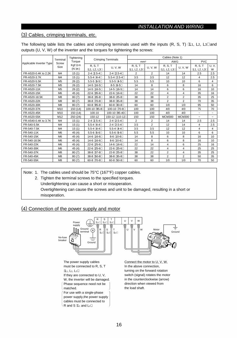
(3) Cables, crimping terminals, etc.
The following table lists the cables and crimping terminals used with the inputs (R, S, T) ⟨L1, L2, L3⟩ andoutputs (U, V, W) of the inverter and the torques for tightening the screws:
Cables (Note 1)Crimping Terminals
mm2 AWG PVCApplicable Inverter TypeTerminal
ScrewSize
TighteningTorqueKgf ⋅cm(N ⋅m )
R, S, T⟨L1, L2, L3⟩
U, V, WR, S, T
⟨L1, L2, L3⟩U, V, W
R, S, T⟨L1, L2, L3⟩
U, V, WR, S, T
⟨L1, L2, L3⟩U, V,
WFR-A520-0.4K to 2.2K M4 15 (1) 2-4 ⟨2.5-4⟩ 2-4 ⟨2.5-4⟩ 2 2 14 14 2.5 2.5FR-A520-3.7K M4 15 (1) 5.5-4 ⟨4-4⟩ 5.5-4 ⟨2.5-4⟩ 3.5 3.5 12 12 4 2.5FR-A520-5.5K M5 26 (2) 5.5-5 ⟨6-5⟩ 5.5-5 ⟨4-5⟩ 5.5 5.5 10 10 6 4FR-A520-7.5K M5 26 (2) 14-5 ⟨16-5⟩ 8-5 ⟨6-5⟩ 14 8 6 8 16 6FR-A520-11K M5 26 (2) 14-5 ⟨16-5⟩ 14-5 ⟨16-5⟩ 14 14 6 6 16 10FR-A520-15K M6 45 (4) 22-6 ⟨35-6⟩ 22-6 ⟨16-6⟩ 22 22 4 4 35 16FR-A520-18.5K M8 80 (7) 38-8 ⟨35-8⟩ 38-8 ⟨25-8⟩ 38 38 2 2 35 25FR-A520-22K M8 80 (7) 38-8 ⟨70-8⟩ 38-8 ⟨35-8⟩ 38 38 2 2 70 35FR-A520-30K M8 80 (7) 60-8 ⟨95-8⟩ 60-8 ⟨30-8⟩ 60 60 1/0 1/0 95 50FR-A520-37K M10 150 (14) 100-10 ⟨95-8⟩ 100-10 ⟨70-8⟩ 100 100 4/0 4/0 75 70FR-A520-45K M10 150 (14) 100-10 100-10 ⟨95-40⟩ 100 100 4/0 4/0 − −FR-A520-55K M12 250 (24) 150-12 150-12 ⟨110-12⟩ 150 150 MCM300 MCM300 − −FR-A540-0.4K to 3.7K M4 15 (1) 2-4 ⟨2.5-4⟩ 2-4 ⟨2.5-4⟩ 2 2 14 14 2.5 2.5FR-540-5.5K M4 15 (1) 5.5-4 ⟨4-4⟩ 2-4 ⟨2.5-4⟩ 3.5 2 12 14 4 2.5FR-540-7.5K M4 15 (1) 5.5-4 ⟨4-4⟩ 5.5-4 ⟨4-4⟩ 3.5 3.5 12 12 4 4FR-540-11K M6 45 (4) 5.5-6 ⟨6-6⟩ 5.5-6 ⟨6-6⟩ 5.5 5.5 10 10 6 6FR-540-15K M6 45 (4) 14-6 ⟨16-6⟩ 8-6 ⟨10-6⟩ 14 8 6 8 16 10FR-540-18.5K M6 45 (4) 14-6 ⟨16-6⟩ 8-6 ⟨10-6⟩ 14 8 6 8 16 10FR-540-22K M6 45 (4) 22-6 ⟨25-6⟩ 14-6 ⟨16-6⟩ 22 14 4 6 25 16FR-540-30K M6 45 (4) 22-6 ⟨25-6⟩ 22-6 ⟨25-6⟩ 22 22 4 4 25 25FR-540-37K M8 80 (7) 38-8 ⟨37-8⟩ 22-8 ⟨25-8⟩ 38 22 2 4 35 25FR-540-45K M8 80 (7) 38-8 ⟨50-8⟩ 38-8 ⟨35-8⟩ 38 38 2 2 50 35FR-540-55K M8 80 (7) 60-8 ⟨70-8⟩ 60-8 ⟨50-8⟩ 60 60 1/0 1/0 70 50
Note: 1. The cables used should be 75°C (167°F) copper cables.2. Tighten the terminal screws to the specified torques.
Undertightening can cause a short or misoperation.Overtightening can cause the screws and unit to be damaged, resulting in a short ormisoperation.
(4) Connection of the power supply and motor
Ground
Ground
Groundterminal
Powersupply
U V W
U V W Motor
No-fusebreaker
The power supply cablesmust be connected to R, S, T ⟨L1, L2, L3⟩.If they are connected to U, V, W, the inverter will be damaged.Phase sequence need not be matched.For use with a single-phasepower supply,the power supplycables must be connected toR and S ⟨L1 and L2⟩.
Connect the motor to U, V, W.In the above connection,turning on the forward rotationswitch (signal) rotates the motorin the counterclockwise (arrow)direction when viewed fromthe load shaft.
R⟨L1⟩
S⟨L2⟩
T⟨L3⟩
R⟨L1⟩
S⟨L2⟩
T⟨L3⟩

INSTALLATION AND WIRING
17
(5) Connecting the control circuit to a power supply separately from the main circuit
If the magnetic contactor (MC) in the inverter power supply is opened when the protective circuit is operated,the inverter control circuit power is lost and the alarm output signal cannot be kept on. To keep the alarmsignal on terminals R1 and S1 are available. In this case, connect the power supply terminals R1 and S1 ⟨L11
and L21⟩ of the control circuit to the primary side of the MC.
• Model FR-A520-0.4K to 3.7K, FR-A540-0.4K to 3.7K
<Connection procedure>
R ⟨L1⟩ S
⟨L2⟩ T ⟨L3⟩
R1 ⟨L11⟩S1 ⟨L21⟩
4) Connect the separate power supply cables for control circuit to the lower terminals (R1, S1 ⟨L11, L21⟩). (Note 4)
Terminal block for main circuit
1) Loosen the upper screws2) Remove the lower screws.3) Remove the jumpers.
• Model FR-A520-5.5K to 55K, FR-A540-5.5K to 55K
<Connection procedure>
MC
1) Loosen the upper screws.2) Remove the lower screws.3) Pull out and remove the jumper.4) Connect the separate power supply cables for control circuit to the upper terminals (R1, S1 ⟨L11, L21⟩). (Note 4)
Power supply terminal block for control circuit
Main power supply
Power supply terminalblock for control circuit
R⟨L1⟩
S⟨L2⟩
T⟨L3⟩
R1⟨L11⟩
S1⟨L21⟩
Note: 1. When the main circuit power (R, S, T) ⟨L1 L2, L3⟩ is on, do not switch off the control power(terminals R1, S1 ⟨L11, L21⟩). Otherwise the inverter may be damaged.
2. When using a separate power supply, the jumpers across R-R1 and S-S1 ⟨L1-L11 and L2-L21⟩must be removed. Otherwise the inverter may be damaged.
3. For a different power supply system which takes the power of the control circuit from other thanthe primary side of the MC, the voltage should be equal to the main circuit voltage.
4. For the FR-A520-5.5K to 55K, FR-A540-5.5K to 55K, the power supply cables must not beconnected to the lower terminals. If connected, the inverter may be damaged.

INSTALLATION AND WIRING
18
2.2.3 Wiring of the control circuit
(1) Wiring instructions
1) Terminals SD, SE and 5 are common to the I/O signals and isolated from each other. These commonterminals must not be connected to each other or earthed.
2) Use shielded or twisted cables for connection to the control circuit terminals and run them away from themain and power circuits (including the 200V relay sequence circuit).
3) The frequency input signals to the control circuit are micro currents. When contacts are required, use twoor more parallel micro signal contacts or a twin contact to prevent a contact fault.
4) It is recommended to use the cables of 0.75mm2 gauge for connection to the control circuit terminals.If the cable gauge used is 1.25mm2 or more, the front cover may be lifted when there are many cablesrunning or the cables are run improperly, resulting in an operation panel or parameter unit contact fault.
(2) Terminal block layout
•Japanese and NA versionIn the control circuit of the inverter, the terminals are arranged as shown below:Terminal screw size: M3.5
A
RL
SE RUN SU IPF OL FU SD STF STR JOG CS
RM RH RT AU STOP MRS RES SD FM
B C PC AM 10E 10 2 5 4 1
•EC versionTerminal screw size: M3.5
A
SE RUN SU LPF OL STOP MRS RES PC STF
B C SD AM 10E 10 2 5 4 1 RL RM RH RT AU
STR JOG CS FM SDFU
<Wiring procedure>
1) For the wiring of the control circuit, strip the sheaths of the cables and use them as they are.Strip the sheath to the following dimension. A too long stripping dimension may cause a short circuit withthe neighboring cable. A too short dimension may cause cable disconnection.
6mm ± 1mm
2) Loosen the terminal screw and insert the cable into the terminal.3) Tighten the screw to the specified torque.
Undertightening can cause cable disconnection or malfunction. Overtightening can cause a short circuit ormalfunction due to the screw or unit damaged.
Tightening torque: 5 to 6 kgf⋅cmNote: Wire the stripped cable by twisting it to prevent it from becoming loose. (Do not plate the cable with
solder.)
Note: 1. Use a NFB (No fuse breakers) or fuse on the inverter input (primary) side.2. Make sure that the control circuit terminal wiring does not touch power circuit terminals (or
screws) or conducting power circuit.

INSTALLATION AND WIRING
19
(3) Changing the control logic
The input signals are set to sink logic for the Japanese and NA version, and to source Logic for the ECversion.To change the control logic, the connector on the back of the control circuit terminal block must be moved tothe other position.(The output signals may be used in either the sink or source logic independently of the connector position.)1) Loosen the two mounting screws in both ends of the control circuit terminal block. (The screws cannot be
removed.)With both hands, pull down the terminal block from the back of the control circuit terminals.
2) Remove the connector from the rear surface of the control circuit terminal block and place in requiredLogic position (either Sink or Source).
SO
UR
CE
CO
N3
CO
N2
SIN
KCON1
SIN
KC
ON
3
CO
N2
SO
UR
CE
SIN
KC
ON
3
CO
N2
SO
UR
CE
EC version NA and Japanese version
3) Using care not to bend the pins of the control circuit connector, reinstall the control circuit terminal blockand fix it with the mounting screws.
Note: 1. Make sure that the control circuit connector is fitted correctly.2. While power is on, never disconnect the control circuit terminal block.3. The sink-source logic change-over connector must be fitted in only one of those positions. If it is
fitted in both positions at the same time, the inverter may be damaged.
INSTALLATION AND WIRING
20
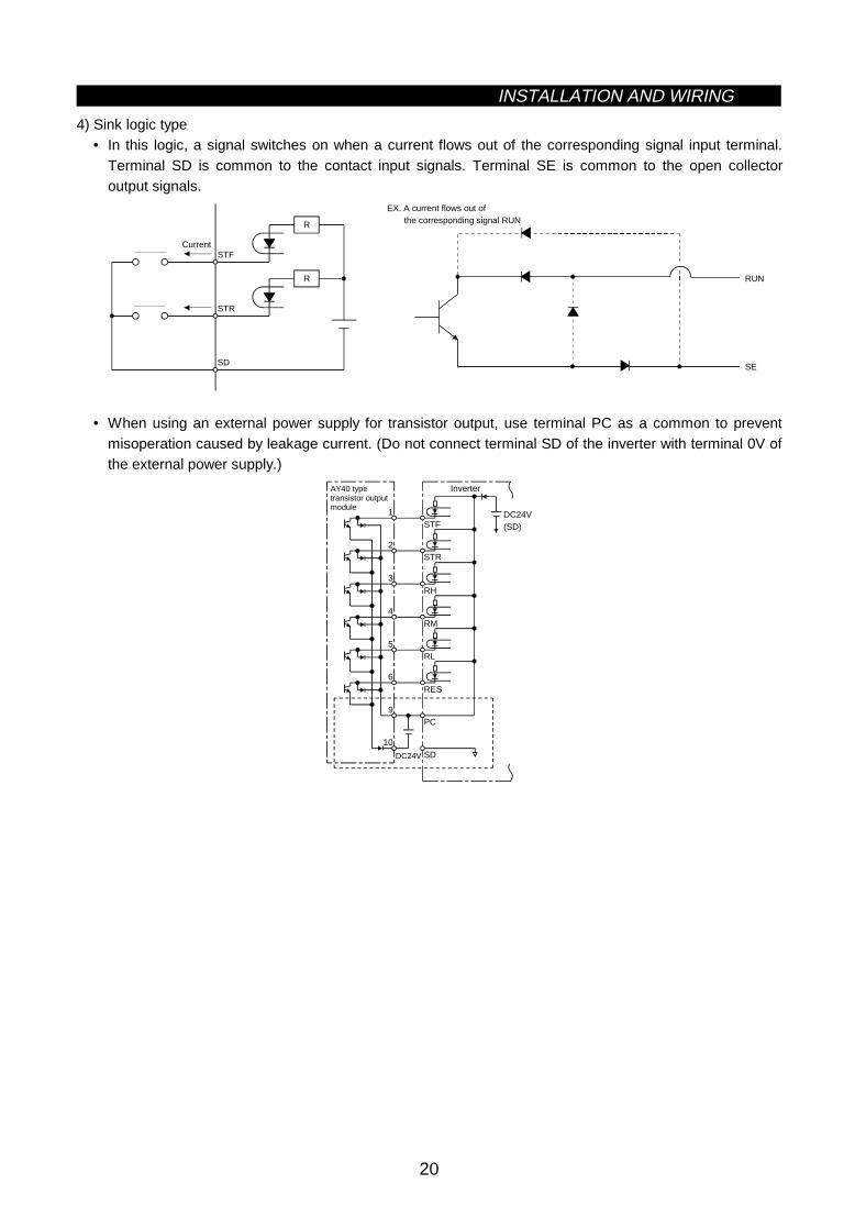
4) Sink logic type• In this logic, a signal switches on when a current flows out of the corresponding signal input terminal.
Terminal SD is common to the contact input signals. Terminal SE is common to the open collectoroutput signals.
R
R
STF
STR
SD
Current
RUN
SE
EX. A current flows out of the corresponding signal RUN
• When using an external power supply for transistor output, use terminal PC as a common to preventmisoperation caused by leakage current. (Do not connect terminal SD of the inverter with terminal 0V ofthe external power supply.)
1
2
3
4
5
6
9
10
DC24V SD
PC
RES
RL
RM
RH
STR
STFDC24V(SD)
AY40 type transistor output module
Inverter

INSTALLATION AND WIRING
21
5) Source logic type• In this logic, a signal switches on when a current flows into the corresponding signal input terminal.
Terminal PC is common to the contact input signals. Terminal SE is common to the open collectoroutput signals.
PC
STF
STRR
R
Current
RUN
SE
EX. A current flows out of the corresponding signal RUN
• When using an external power supply for transistor output, use terminal SD as a common to preventmisoperation caused by leakage current.
AY-809
1
2
10
PC
STF
STR
SD
DC24V(SD)
DC
24V
Inverter
(4) How to use terminals "STOP", "CS" and "PC"
1) Using the "STOP" terminalA connection example (for sink logic) for self-holding the start signal (forwardrotation, reverse rotation) is shown on the right.
2) Using the "CS" terminalThis terminal is used to perform automatic restart after instantaneous power failureand commercial power supply-inverter switch-over operation.<Example: Automatic restart after instantaneous power failure in sink logic>Connect terminals CS-SD and set a value other than "9999" in Pr. 57 "coasting timefor automatic restart after instantaneous power failure".
MRS
RES
SD
STF
STR
STOP
Reverserotation
Stop
Forwardrotation
CS SD
(Short)
3) Using the "PC" terminalThis terminal can be used as 24VDC power output using SD as a common terminal.Specifications: 18V to 26VDC, 0.1A permissible currentNote that the wiring length should be within 30m.Do not short terminals PC-SD.When terminal PC is used as a 24V power supply, leakage current from transistor output cannot beprevented.

INSTALLATION AND WIRING
22
2.2.4 Connection to the PU connector
(1) When connecting the operation panel or parameter unit using a connection cable
<Recommended cable connector>• Parameter unit connection cable (FR-CB2) (option) or the following connector and cable.• Connector: RJ45 connector
Example: 5-554720-3, Nippon AMP• Cable: Cable conforming to EIA568 (e.g. 10BASE-T cable)
Example: SGLPEV 0.5mm×4P, MITSUBISHI CABLE INDUSTRIES, LTD.
Note: The maximum wiring length is 20m (65.62 feet).
(2) For RS-485 communication
With the operation panel disconnected, the PU connector can be used for communication operation from apersonal computer etc.When the PU connector is connected with a personal, FA or other computer by a communication cable, auser program allows the inverter to be run and monitored and the parameter values to be read and written.<PU connector pin-outs>Viewed from the inverter (receptacle side) front
1) SG2) P5S3) RDA4) SDB
5) SDA6) RDB7) SG8) P5S
1)
8)
Note: 1. Do not connect the PU connector to the computer's LAN board, FAX modem socket ortelephone modular connector. Otherwise, the product may be damaged due to electricalspecification differences.
2. Pins 2 and 8 (P5S) provide power to the operation unit or parameter unit. Do not use these pinsfor RS-485 communication.
<System configuration example>
1) When a computer having a RS-485 interface is used with several inverters
PU connectorPU connector
Computer
Inverter
Station 1
PU connector
Inverter
Station 2
Inverter
Station n
RS-485 interface/terminal Computer
10BASE-T cable
Terminal resistor jumperDistribution terminal
Note: 1. Use the connector and cables which are available on the market.x Connector: RJ45 connector
Example: 5-554720-3, Nippon AMP Co., Ltd.x Cable: Cable conforming to EIA568B (such as 10BASE-T cable)
Example: SGLPEV 0.5mm×4P, Mitsubishi Cable Industries, Ltd.
INSTALLATION AND WIRING
23
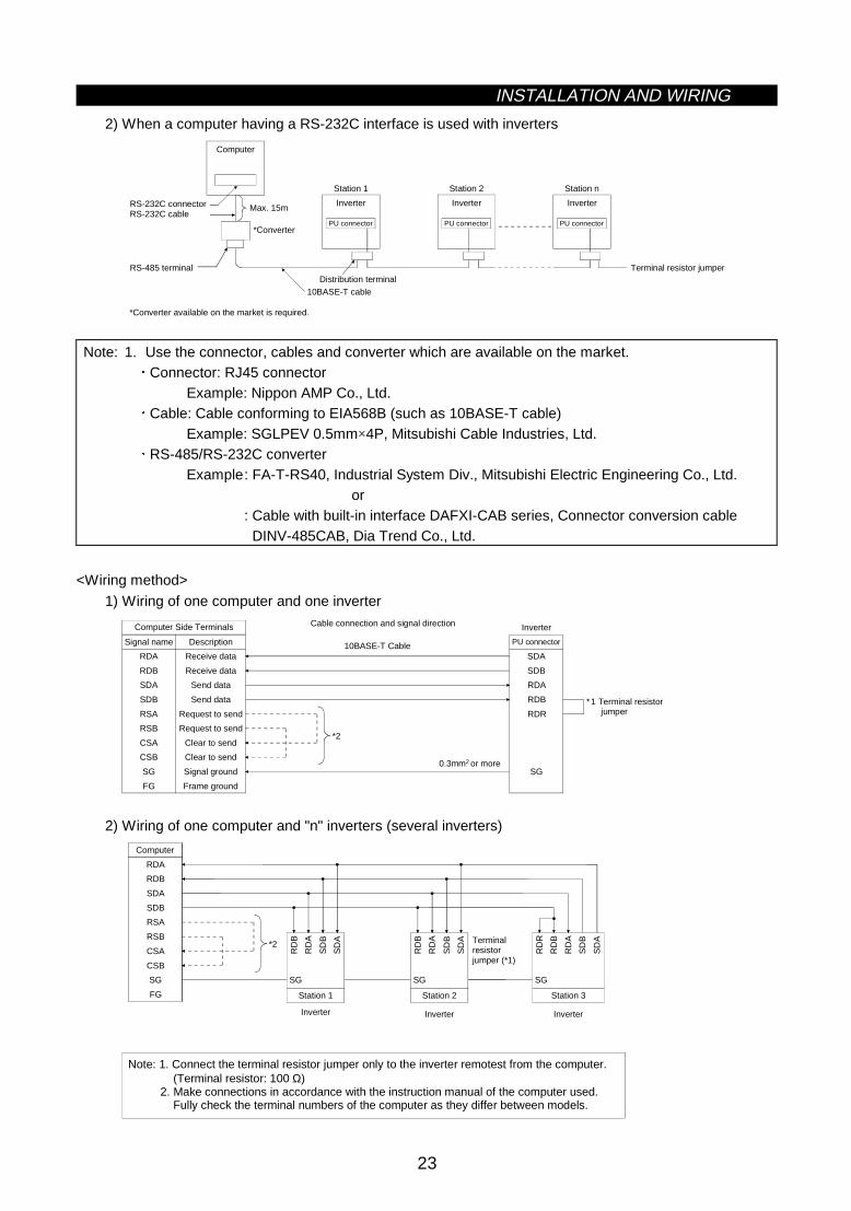
2) When a computer having a RS-232C interface is used with inverters
Computer
Inverter
Station 1
PU connector
Inverter
Station 2
PU connector
Inverter
Station n
PU connector
Terminal resistor jumper
Max. 15mRS-232C connectorRS-232C cable
RS-485 terminal
*Converter
*Converter available on the market is required.
10BASE-T cableDistribution terminal
Note: 1. Use the connector, cables and converter which are available on the market.x Connector: RJ45 connector
Example: Nippon AMP Co., Ltd.x Cable: Cable conforming to EIA568B (such as 10BASE-T cable)
Example: SGLPEV 0.5mm×4P, Mitsubishi Cable Industries, Ltd.x RS-485/RS-232C converter
Example: FA-T-RS40, Industrial System Div., Mitsubishi Electric Engineering Co., Ltd.or
: Cable with built-in interface DAFXI-CAB series, Connector conversion cable DINV-485CAB, Dia Trend Co., Ltd.
<Wiring method>
1) Wiring of one computer and one inverter
Computer Side Terminals
Signal name Description
RDA
RDB
SDA
SDB
RSA
RSB
CSA
CSB
SG
FG
Receive data
Receive data
Send data
Send data
Request to send
Request to send
Clear to send
Clear to send
Signal ground
Frame ground
PU connector
SDA
SDB
RDA
RDB
RDR
SG
*2
∗1 Terminal resistor jumper
0.3mm or more2
Cable connection and signal direction
10BASE-T Cable
Inverter
2) Wiring of one computer and "n" inverters (several inverters)
*2
Computer
RDA
RDB
SDA
SDB
RSA
RSB
CSA
CSB
SG
FG Station 1
SG
RD
B
RD
A
SD
B
SD
A
Station 2
SG
RD
B
RD
A
SD
B
SD
A
Station 3
SG
RD
R
RD
B
RD
A
SD
B
SD
ATerminal resistor jumper (*1)
Inverter Inverter Inverter
Note: 1. Connect the terminal resistor jumper only to the inverter remotest from the computer. (Terminal resistor: 100 Ω) 2. Make connections in accordance with the instruction manual of the computer used. Fully check the terminal numbers of the computer as they differ between models.

INSTALLATION AND WIRING
24
2.2.5 Connection of stand-alone option units
The inverter accepts a variety of stand-alone option units as required.Incorrect connection will cause inverter damage or accident. Connect and operate the option unit carefully inaccordance with the corresponding option unit manual.
(1) Connection of the dedicated external brake resistor (option)
The built-in brake resistor is connected across terminals P ⟨+⟩ and PR. Fit the external dedicated brakeresistor (option) instead when the built-in brake resistor does not have enough thermal capability for high-dutyoperation. Remove the jumper from across terminals PR-PX and connect the dedicated brake resistor(option) across terminals P-PR ⟨+ -PR⟩.(For the positions of terminals P and PR, refer to the terminal block arrangement (page14 and 15).)
Note: 1. The brake resistor connected should only be the dedicated brake resistor.2. The jumper across terminals PR-PX must be disconnected before connecting the dedicated
brake resistor. A failure to do so may damage the inverter.
• Model...............FR-A520-0.4K to 3.7K, FR-A540-0.4K to 3.7K1) Remove the screws in terminals PR and PX and remove the jumper.2) Connect the brake resistor across terminals P-PR ⟨+ -PR⟩.
(The jumper should remain disconnected.)
Removal of jumper FR-A520-0.4K, 0.75KFR-A520-1.5K to 3.7KFR-A540-0.4K to 3.7K
Terminal PX
Terminal PR
Jumper
Terminal PR
Terminal P
Terminal PRTerminal P
• Model...............FR-A520-5.5K, 7.5K, FR-A540-5.5K, 7.5K1) Remove the screws in terminals PR and PX and remove the jumper.2) Connect the brake resistor across terminals P-PR ⟨+ -PR⟩.
(The jumper should remain disconnected.)
Removal of jumperFR-A520-5.5K, 7.5KFR-A540-5.5K, 7.5K
Jumper
Terminal PR
Terminal PX
Terminal PRTerminal PR

INSTALLATION AND WIRING
25
(2) Connection of the FR-BU brake unit (option)
Connect the optional FR-BU brake unit as shown below to improve the braking capability during deceleration.
MC
R ⟨L1⟩
S ⟨L2⟩
T ⟨L3⟩
U
V
W
⟨+⟩ P
⟨–⟩ N
PR
PX
IM
PR
P/+
N/-
HAHB
HC
Brake unitFR-BU-(H)
Resistor unitFR-BR-(H)
THS TH2
TH1
PPR
ON
MC
OFFMC
Remove jumper.
Inverter
Motor
T (Note 4)
Note: 1. Connect the inverter terminals (P, N) ⟨+, −⟩ and FR-BU brake unit terminals so that their terminalsignals match with each other. (Incorrect connection will damage the inverter.) For model 7.5K orless, the jumper across terminals PR-PX must be removed.
2. The wiring distance between the inverter, brake unit and resistor unit should be within 5m (16.40feet). If twisted wires are used, the distance should be within 10m (32.8 feet).
3. If the transistors in the brake unit should fail, the resistor will be extremely hot, causing a fire.Therefore, install a magnetic contactor on the inverter's power supply side to shut off a current incase of failure.
4. For the power supply of 400V class, install a voltage-reducing transformer.

INSTALLATION AND WIRING
26
(3) Connection of the conventional BU brake unit (option)
Connect the BU brake unit correctly as shown on the right. Incorrect connection will damage the inverter.
MC
R ⟨L1⟩
S ⟨L2⟩
T ⟨L3⟩
U
V
W
IM
Inverter
HCHBHA TB
HC HBON
MC
MCOFF
P ⟨+⟩ N ⟨–⟩
P
OCR
PR
OCR
N
NFB
PC
Brake unit
Remove jumpers.
Discharge resistor
Constant-voltagepower supply
BU brake unit
Comparator
Motor
T (Note 4)
+
-
Note: 1. For models 7.5K or less, remove the jumper across terminals PR-PX.2. The wiring distance between the inverter, brake unit and discharge resistor should be within
2m (6.56 feet).If twisted wires are used, the distance should be within 5m (16.40 feet).
3. If the transistors in the brake unit should fail, the resistor will be extremely hot, causing a fire.Therefore, install a magnetic contactor on the inverter's power supply side to shut off current incase of failure.
4. For the power supply of 400V class, install a voltage-reducing transformer.
(4) Connection of the FR-HC high power factor converter (option)
When connecting the high power factor converter (FR-HC) to suppress power harmonics, wire as shownbelow. Wrong connection will damage the high power factor converter and inverter.After making sure that the wiring is correct, set "2" in Pr. 30 "regenerative function selection".
X10 (Note 3)
X11 (Note 3)
N ⟨–⟩
P ⟨+⟩
R1 ⟨L11⟩
S1 ⟨L21⟩
RES
SD
T ⟨L3⟩
S ⟨L2⟩ (Note 1)
R ⟨L1⟩
NFB
R S T R4 S4 T4 N P Y1 or Y2 RDY RSO SE
Inverter(FR-A500)
(Note 1)
High power factor converter
From FR-HCL02
Powersupply

INSTALLATION AND WIRING
27
Note: 1. Remove the jumpers across the R-R1 and S-S1 ⟨L1-R1 and L2-S1⟩ terminals of the inverter, andconnect the control circuit power supply across the R1-S1 ⟨L11-L21⟩ terminals. The power inputterminals R, S, T ⟨L1, L2, L3⟩ must be open.Incorrect connection will damage the inverter. Reverse polarity of terminals N (−), P (+) willdamage the inverter.
2. The voltage phases of terminals R, S, T ⟨L1, L2, L3⟩ and terminals R4, S4, T4 must be matchedbefore connection.
3. Use Pr. 180 to Pr. 186 (input terminal function selection) to assign the terminals used with theX10 and X11 signals.
4. When the FR-HC is connected, use sink logic (factory setting). For source logic, the FR-HCcannot be connected. (For the EC version, select the sink logic.)
(5) Connection of the FR-RC power return converter (option)
(For power coordination, always install the power factor improving reactor (FR-BAL).)When connecting the FR-RC power return converter, connect the inverter terminals (P, N) and FR-RC powerreturn converter terminals as shown below so that their signals match with each other. After making sure thatthe wiring is correct, set "0" in Pr. 30 "regenerative function selection".
N P
NFB FR-BAL R/L1 S/L2 T/L3
P/+
N/−
FR-RC power return converter
Power supply
InverterR
⟨L1⟩S
⟨L2⟩T
⟨L3⟩
Note: 1. For models 11K or less, the jumper across terminals PR-PX must be removed.2. How to connect the FR-BAL power factor improving AC reactor (option)
When using two or more inverters in the same system, small impedance between the inverterswill cause a regenerative current from the power return converter to leak into the other inverters,resulting in overcurrent alarm of the other inverters. To prevent this, install a power factorimproving AC reactor on the power supply side for all the inverters.
(6) Connection of the power factor improving DC reactor (option)
Connect the FR-BEL power factor improving DCreactor between terminals P1-P ⟨P1- +⟩. In thiscase, the jumper connected across terminals P1-P⟨P1- +⟩ must be removed. Otherwise, the reactorwill not function.
• <Connection method>
P1 P
FR-BEL
Remove the jumper.
⟨+⟩
Note: 1. The wiring distance should be within 5m.2. The size of the cables used should be equal to or larger than that of the power supply cables
(R, S, T) ⟨L1, L2, L3⟩.

INSTALLATION AND WIRING
28
2.2.6 Design information
1) For commercial power supply-inverter switch-over operation, provide electrical and mechanical interlocksfor MC1 and MC2 designed for commercial power supply-inverter switch-over.When there is a commercial power supply-inverter switch-over circuit as shown below, the inverter will bedamaged by leakage current from the power supply due to arcs generated at the time of switch-over orchattering caused by a sequence error.
2) If the machine must not be restarted when power is restored after a power failure, provide a magneticcontactor in the inverter's primary circuit and also make up a sequence which will not switch on the startsignal.If the start signal (start switch) remains on after a power failure, the inverter will automatically restart assoon as the power is restored.
3) When the power supply used with the control circuit is different from the one used with the main circuit,make up a circuit which will switch off the main circuit power supply terminals R, S, T ⟨L1, L2, L3⟩ when thepower supply terminals R1, S1 ⟨L11, L21⟩ for the control circuit are switched off.
4) Since the input signals to the control circuit are on a low level, use two parallel micro signal contacts or atwin contact for contact inputs to prevent a contact fault.
5) Do not apply a large voltage to the contact input terminals (e.g. STF) of the control circuit.
6) Do not apply a voltage directly to the alarm output signal terminals (A, B, C).Always apply a voltage to these terminals via a relay coil, lamp, etc.
7) Make sure that the specifications and rating match the system requirements.
1) Commercial power supply-inverter switch-over
U
V
W
R (L1)
S (L2)
T (L3)
IMMC2
MC1Interlock
Leakage current
Inverter
Powersupply
4) Low-level signal contacts
Twin contactLow-level signal contacts

2.3 Other wiringINSTALLATION AND WIRING
29
2.3 Other wiring
2.3.1 Power harmonics
Power harmonics may be generated from the converter section of the inverter, affecting power supplyequipment, power capacitors, etc. Power harmonics are different in generation source, frequency andtransmission path from radio frequency (RF) noise and leakage currents. Take the following measures.
• The differences between harmonics and RF noise are indicated below:
Item Harmonics RF NoiseFrequency Normally 40 to 50th degrees, 3kHz or less High frequency (several 10kHz to MHz order)Environment To wire paths, power impedance Accross spaces, distance, laying pathsQuantitative understanding Logical computation is possible Occurs randomly, quantitative understanding is difficult.
Generated amount Approximately proportional to load capacityAccording to current fluctuation rate (larger with fasterswitching)
Immunity of affected device Specified in standards for each device. Differs according to maker’s device specifications.Example of safeguard Install a reactor Increase the distance.
• SafeguardThe harmonic current generated from the inverter to thepower supply differs according to various conditions such asthe wiring impedance, whether a power factor improvingreactor is used or not, and output frequency and outputcurrent on the load side.For the output frequency and output current, the adequatemethod is to obtain them under rated load at the maximumoperating frequency.
NFB
IMInverter
Power factorimproving DCreactor
Motor
Do not insert power factor improving capacitor
Power factorimproving ACreactor
Note: A power factor improving capacitor or surge suppressor on the inverter’s output may overheat or bedamaged due to the harmonics of the inverter output. Also, when an overcurrent flows in the inverter,the overcurrent protection is activated, Hence, when the motor is driven by the inverter, do not installa capacitor or surge suppressor on the inverter’s output. To improve the power factor, insert a powerfactor improving reactor in the inverter’s input or DC circuit.

INSTALLATION AND WIRING
30
2.3.2 Japanese harmonic suppression guidelines
Harmonic currents flow from the inverter to a power receiving point via a power transformer. The harmonicsuppression guidelines were established to protect other consumers from these outgoing harmonic currents.1) "Harmonic suppression guideline for household appliances and general-purpose products"
This guideline was issued by the Ministry of International Trade and Industries in September, 1994 andapplies to 200V class inverters of 3.7kW (5HP) and less. By installing the FR-BEL or FR-BAL power factorimproving reactor, inverters comply with the "harmonic suppression techniques for transistorized inverters(input current 20A or less)" established by the Japan Electrical Manufacturers' Association. Thereforeinstall the optional reactor for the 200V class, 3.7kW (5HP) or less inverter.
2) "Harmonic suppression guideline for specific consumers"This guideline sets forth the maximum values of harmonic currents outgoing from a high-voltage orespecially high-voltage consumer who will install, add or renew harmonic generating equipment. If any ofthe maximum values are exceeded, this guideline requires that consumer to take certain suppressionmeasures.
Table 1 Maximum Values of Outgoing Harmonic Currents per 1kW Contract Power
Received PowerVoltage
5th 7th 11th 13th 17th 19th 23rd Over 23rd
6.6kV 3.5 2.5 1.6 1.3 1.0 0.9 0.76 0.7022kV 1.8 1.3 0.82 0.69 0.53 0.47 0.39 0.3633kV 1.2 0.86 0.55 0.46 0.35 0.32 0.26 0.24
(1) Application of the harmonic suppression guideline for specific consumers
New installation/addition/renewal of equipment
Sum of equivalent capacities
Over reference capacity
Is outgoing harmonic cur-rent equal to or lower than
maximum value ?
Over maximum value
Not more thanmaximum value
Not more thanreference capacity
Calculation of equivalent capacity sum
Calculation of outgoing harmomic current
Harmomic suppression technique is required.
Harmomic suppression technique is not required.
Table 2 Conversion Factors for FR-A500 Series
Class Circuit Type Conversion FactorWithout reactor K31 = 3.4With reactor (AC side) K32 = 1.8With reactor (DC side) K33 = 1.8
33-phase bridge(Capacitor-smoothed)
With reactors (AC, DC sides) K34 = 1.45 Self-exciting 3-phase bridge When high power factor converter is used K5 = 0

INSTALLATION AND WIRING
31
Table 3 Equivalent Capacity Limits
Received Power Voltage Reference Capacity
6.6kV 50kVA
22/33kV 300kVA
66kV or more 2000kVA
Table 4 Harmonic Content (Values at the fundamental current of 100%)
Reactor 5th 7th 11th 13th 17th 19th 23rd 25thNot used 65 41 8.5 7.7 4.3 3.1 2.6 1.8Used (AC side) 38 14.5 7.4 3.4 3.2 1.9 1.7 1.3Used (DC side) 30 13 8.4 5.0 4.7 3.2 3.0 2.2Used (AC, DC sides) 28 9.1 7.2 4.1 3.2 2.4 1.6 1.4
1) Calculation of equivalent capacity (P0) of harmonic generating equipmentThe “equivalent capacity” is the capacity of a 6-pulse converter converted from the capacity of consumer’sharmonic generating equipment and is calculated with the following equation. If the sum of equivalentcapacities is higher than the limit in Table 3, harmonics must be calculated with the following procedure:
P0 = Σ (Ki × Pi) [kVA]Ki: Conversion factor (refer to Table 2)Pi: Rated capacity of harmonic generating equipment* [kVA] I : Number indicating the conversion circuit type
*: Rated capacity: Determined by the capacityof the applied motor and found in Table 5. Itshould be noted that the rated capacityused here is used to calculate generatedharmonic amount and is different from thepower supply capacity required for actualinverter drive.
2) Calculation of outgoing harmonic currentOutgoing harmonic current = fundamental wave current (value converted from received power voltage) ×operation ratio × harmonic content
• Operation ratio: Operation ratio = actual load factor × operation time ratio during 30 minutes• Harmonic content: Found in Table 4.
Table 5 Rated Capacities and Outgoing Harmonic Currents for Inverter Drive
Rated Current [A]
FundamentalWave Current
Converted from6.6kV
RatedCapacity
Fundamental Wave Current Converted from 6.6kV(No reactor, 100% operation ratio)
AppliedMotor
(kW (HP))200V 400V (mA) (kVA) 5th 7th 11th 13th 17th 19th 23rd 25th
0.4 (0.5) 0.81 49 0.57 31.85 20.09 4.165 3.773 2.107 1.519 1.274 0.8820.75 (1) 1.37 83 0.97 53.95 34.03 7.055 6.391 3.569 2.573 2.158 1.4941.5 (2) 2.75 167 1.95 108.6 68.47 14.20 12.86 7.181 5.177 4.342 3.0062.2 (3) 3.96 240 2.81 156.0 98.40 20.40 18.48 10.32 7.440 6.240 4.3203.7 (5)
Notapplied
6.50 394 4.61 257.1 161.5 33.49 30.34 16.94 12.21 10.24 7.0925.5 (7.5) 19.1 9.55 579 6.77 376.1 237.4 49.22 44.58 24.90 17.95 15.05 10.427.5 (10) 25.6 12.8 776 9.07 504.4 318.2 65.96 59.75 33.37 24.06 20.18 13.9711 (15) 36.9 18.5 1121 13.1 728.7 459.6 95.29 86.32 48.20 34.75 29.15 20.1815 (20) 49.8 24.9 1509 17.6 980.9 618.7 128.3 116.2 64.89 46.78 39.24 27.16
18.5 (25) 61.4 30.7 1860 21.8 1209 762.6 158.1 143.2 79.98 57.66 48.36 33.4822 (30) 73.1 36.6 2220 25.9 1443 910.2 188.7 170.9 95.46 68.82 57.72 39.9630 (40) 98.0 49.0 2970 34.7 1931 1218 252.5 228.7 127.7 92.07 77.22 53.4637 (50) 121 60.4 3660 42.8 2379 1501 311.1 281.8 157.4 113.5 95.16 65.8845 (60) 147 73.5 4450 52.1 2893 1825 378.3 342.7 191.4 138.0 115.7 80.1055 (75) 180 89.9 5450 63.7 3543 2235 463.3 419.7 234.4 169.0 141.7 98.10
3) Harmonic suppression technique requirementIf the outgoing harmonic current is higher than; maximum value per 1kW (contract power) × contractpower, a harmonic suppression technique is required.

INSTALLATION AND WIRING
32
4) Harmonic suppression techniques
No. Item Description
1Reactor installation(ACL, DCL)
Install a reactor (ACL) in the AC side of the inverter or a reactor (DCL) in its DC side or both tosuppress outgoing harmonic currents.
2High power factorconverter(FR-HC)
The converter circuit is switched on-off to convert an input current waveform into a sine wave,suppressing harmonic currents substantially. The high power factor converter (FR-HC) is usedwith the standard accessory.
3Installation of powerfactor improvingcapacitor
When used with a series reactor, the power factor improving capacitor has an effect of absorbingharmonic currents.
4Transformer multi-phase operation
Use two transformers with a phase angle difference of 30° as in Y-∆, ∆-∆ combination to providean effect corresponding to 12 pulses, reducing low-degree harmonic currents.
5 AC filterA capacitor and a reactor are used together to reduce impedance at specific frequencies,producing a great effect of absorbing harmonic currents.
6 Active filter
This filter detects the current of a circuit generating a harmonic current and generates aharmonic current equivalent to a difference between that current and a fundamental wavecurrent to suppress a harmonic current at a detection point, providing a great effect of absorbingharmonic currents.

INSTALLATION AND WIRING
33
2.3.3 Inverter-generated noises and reduction techniques
Some noises enter the inverter causing it to misoperate and others are radiated by the inverter causingmisoperation of peripheral devices. Though the inverter is designed to be insusceptible to noise, it handleslow-level signals, so it requires the following basic measures to be taken. Also, since the inverter chops theoutput at a high carrier frequency, it could generate noise. If these noises cause peripheral devices tomisoperate, measures should be taken to suppress the noise. The measures differ slightly depending onnoise propagation paths.
1) Basic measures• Do not run the power cables (I/O cables) and signal cables of the inverter in parallel with each other and
do not bundle them.• Use twisted shielded cables for the detector connection and control signal cables and connect the
sheathes of the shielded cables to terminal SD.• Ground the inverter, motor, etc. at one point.
2) Measures against noises which enter and cause misoperation of the inverterWhen devices which generate many noises (which use magnetic contactors, magnetic brakes, manyrelays, for example) are installed near the inverter and the inverter may be effected by noise, the followingmeasures must be taken:• Provide surge suppressors for devices that generate noise to suppress noise.• Fit data line filters to signal cables.• Ground the shields of the detector connection and control signal cables with cable clamp metal.
3) Measures against noise which is radiated by the inverter causing misoperation of peripheral devices.Inverter-generated noise is largely classified into those radiated by the cables connected to the inverter andinverter main circuit (I/O), those electromagnetically and electrostatically inducted to the signal cables ofthe peripheral devices close to the main circuit power supply, and those transmitted through the powersupply cables.
Air-propagatednoise
Magnetic inductionnoise
Static inductionnoise
Cable-propagatednoise
Noise directly radi-ated by inverter
Noise radiated bypower cables
Noise radiated bymotor cables
Noise propagatedthrough power cables
Noise from ground cable due to leakage current
Path 4),5)
Path 6)
Path 1)
Path 2)
Path 3)
Path 7)
Path 8)
Inverter-generatednoise

INSTALLATION AND WIRING
34
IM
In-verter
Sensor power supply
ReceiverInstrument
Telephone
MotorSensor
5)
7)2)
1)
7)
3)
2)
8)
3)
4)6)
Noise Path Measures
1) 2) 3)
When devices which handle low-level signals and are susceptible to misoperation due to noise (such asinstruments, receivers and sensors) are installed near the inverter and their signal cables are contained in thesame panel as the inverter or are run near the inverter, the devices may be effected by air-propagated noisesand the following measures must be taken:(1) Install easily affected devices as far away as possible from the inverter.(2) Run easily affected signal cables as far away as possible from the inverter.(3) Do not run the signal cables and power cables (inverter I/O cables) in parallel with each other and do not
bundle them.(4) Inset line noise filters into I/O and radio noise filters into input side to suppress cable-radiated noises.(5) Use shielded cables for signal cables and power cables and run them in individual metal conduits to reduce
further effects.
4) 5) 6)
When the signal cables are run in parallel with or bundled with the power cables, magnetic and static inductionnoise may be propagated to the signal cables to effect the devices and the following measures must be taken:(1) Install easily affected devices as far away as possible from the inverter.(2) Run easily affected signal cables as far away as possible form the inverter.(3) Do not run the signal cables and power cables (inverter I/O cables) in parallel with each other and do not
bundle them.(4) Use shield cables for signal cables and power cables and run them in individual metal conduits to reduce
further effects.
7)
When the power supplies of the peripheral devices are connected to the power supply of the inverter within thesame line, inverter-generated noise may flow back through the power supply cables to misoperate the devicesand the following measures must be taken:(1) Install the radio noise filter (FR-BIF) to the power cables (input cables) of the inverter.(2) Install the line noise filter (FR-BLF, FR-BSF01) to the power cables (I/O cables) of the inverter.
8)When a closed loop circuit is formed by connecting the peripheral device wiring to the inverter, leakage currentmay flow through the ground cable of the inverter to effect the device. In such a case, disconnection of theground cable of the device may cause the device to operate properly.

INSTALLATION AND WIRING
35
• Data line filterNoise entry can be prevented by providing a data line filter for the detector cable etc.Example Data line filter: ZCAT3035-1330 (TDK make)
ESD-SR-25 (Tokin make)Impedance specifications (ZCAT3035-1330)
Impedance (Ω)
10 to 100MHz 100 to 500MHz
80 150
The above impedance values are reference valuesand not guaranteed values.
34±1
TDK
39±1
Product name Lot number
φ30 ±
1
Cable fixing band mounting section
φ 13±
1
Outline Dimension Drawing (ZCAT3035-1330)
[Unit : mm]
• Data examplesBy decreasing the carrier frequency, the noise terminal voltage*can be reduced. Use Pr. 72 to set the carrier frequency to a lowvalue (1kHz).Though motor noise increases at a low carrier frequency,selection of Soft-PWM in Pr. 240 will make it unoffending.
Differences between Noise Terminal Voltagesat Different Carrier Frequencies
0.1 0.3 0.5 1 3 5 10 30
20
60
80
100
120
0
FR-A520-3.7K
fc=0.7kHzfc=14.5kHz
fc=2.0kHz Soft-PWM(Factory setting)
FR-A220E-3.7k fc=(14.5kHz)
Conditions Motor: 3.7kW (5HP) Average terminal voltage 0dB=1µV 120dB=1V
Noi
se te
rmin
al v
olta
ge (
dB)
Noise frequency (MHz)
By decreasing the carrier frequency, noise will be about as lowas that of our conventional FR-Z200 series.
By using shielded cables as signal cables, induction noise canbe reduced greatly (to 1/10 - 1/100). Induction noise can also bereduced by moving the signal cables away from the inverteroutput cables. (Separation of 30cm (11.81 inches) reduces noiseto 1/2-1/3.)By fitting the FR-BSF01 or BLF on the inverter output side,induction noise to the signal cables can be reduced.
Noise Terminal Voltage of Inverter and Exampleof Its Reduction by Noise ilters
0.1 0.3 0.5 1 3 5 10 30
20
60
80
100
120
0
FR-A520-3.7k(fc=0.7kHz)
FR-Z220-3.7K
Noise frequency (MHz)
Noi
se te
rmin
al v
olta
ge (
dB)
Conditions Motor:3.7kW (5HP) Average terminal voltage 0dB=1µV 120dB=1V
Noise Induced to Signal Cables by Inverter Output Cables
20
40
60
80
100
100 20 30 40 50
5cmd(cm)
FR-BLFFR-BSF01
(4T)
Line-to-line distance, d (cm)
Indu
ctio
n vo
ltage
(dB
) Parallel cable
Twisted pair cable
Coaxial cable
Conditions Inverter: FR-A520-3.7K Motor: FR-JR 4P 3.7kW (5HP) Output frequency: 30Hz Noise form: Normal mode
Inverter Motor
Terminal
Measuring instrument
*Noise terminal voltage: Represents the magnitude of noise propagated from the inverter to the power supply.

INSTALLATION AND WIRING
36
z Example of measures against noises
FR-BLF
FR-BIF
FR-BLF
Install filter (FR-BLF,FR-BSF01) to inverter input side.
Control boxReduce carrierfrequency.
Install filter (FR-BLF,FR-BSF01)to inverter output side.
Use 4-core cable for motorpower cable and use onecable as ground cable.
Use twisted pairshielded cable.
Sensor
Do not ground shield but connectit to signal common cable.Do not ground control box directly.
Do not ground control cable.
Control powersupply
Separate inverter and power line 30cm (11.81 inches) or more (at least 10cm (3.94 inches)) from sensor circuit.
Install filter FR-BIF toinverter input side.
Inverter powersupply
Powersupply forsensor
Inverter Motor

INSTALLATION AND WIRING
37
2.3.4 Leakage currents and countermeasures
Due to the static capacitance existing in the inverter I/O wiring and motor, leakage currents flow throughthem. Since their values depend on the static capacitance, carrier frequency, etc., take the followingmeasures.
(1) To-ground leakage currents
Leakage currents may flow not only into the inverter's own line but also into the other line through the groundcable, etc. These leakage currents may operate earth leakage circuit breakers and earth leakage relaysunnecessarily.
• Countermeasures⋅ Decrease the carrier frequency (Pr. 72) of the inverter.
Note that motor noise increases. Selection of Soft-PWM (Pr. 240) will make it unoffending.⋅ By using earth leakage circuit breakers designed for harmonics and surges (e.g. Mitsubishi's Progressive
Super Series) in the inverter's own line and other line, operation can be performed with low noise (withthe carrier frequency kept high)
• To-ground leakage current⋅ Note that a long wiring length will increase leakage currents. Decrease the carrier frequency of the
inverter to reduce leakage currents.⋅ Higher motor capacity leads to larger leakage currents. Larger leakage currents occur in 400V class than
in 200V class.
(2) Line-to-line leakage currents
Harmonics of leakage currents flowing in static capacities between the inverter output cables may operate theexternal thermal relay unnecessarily. When the wiring length is long (50m (164.04 feet) or more) for the 400Vclass small-capacity model (7.5kW (10HP) or less), the external thermal relay is likely to operateunnecessarily because the ratio of the leakage current to the rated motor current increases.
• Line-to-Line Leakage Current Data Example (200V class)Leakage Current (mA)
Motor Capacity(kW (HP))
Rated MotorCurrent (A) Wiring length 50m
(164.04 feet)Wiring length 100m
(328.08 feet)0.4 (0.5) 1.8 310 5000.75 (1) 3.2 340 5301.5 (2) 5.8 370 5602.2 (3) 8.1 400 5903.7 (5) 12.8 440 630
5.5 (7.5) 19.4 490 6807.5 (10) 25.6 535 725
Motor: SF-J 4P Carrier frequency: 14.5Hz Cable used: 2mm2 4-core
cable
* Leakage current of the 400V class is about twice larger.
IM
NFB
Line-to-Line Leakage Current Path
Power supply
Inverter
Thermal relay
Line static capacitances
Motor
• Countermeasures⋅ Use the electronic overcurrent protection (Pr. 9) of the inverter.⋅ Decrease the carrier frequency. Note that motor noise increases. Selection of Soft-PWM (Pr. 240) will
make it unoffending.To ensure that the motor is protected against line-to-line leakage currents, it is recommended to use atemperature sensor to directly detect motor temperature.

INSTALLATION AND WIRING
38
2.3.5 Inverter-driven 400V class motor
In the PWM type inverter, a surge voltage attributable to wiring constants is generated at the motor terminals.Especially for a 400V class motor, the surge voltage may deteriorate the insulation. When the 400V classmotor is driven by the inverter, consider the following measures:
• MeasuresIt is recommended to take either of the following measures:(1) Rectifying the motor insulation
For the 400V class motor, use an insulation-rectified motor. Specifically,1) Specify the “400V class inverter-driven, insulation-rectified motor”.2) For the dedicated motor such as the constant-torque motor and low-vibration motor, use the
“inverter-driven, dedicated motor”.
(2) Suppressing the surge voltage on the inverter sideOn the secondary side of the inverter, connect the optional surge voltage suppression filter (FR-ASF-H).

INSTALLATION AND WIRING
39
2.3.6 Peripheral devices
(1) Selection of peripheral devices
Check the capacity of the motor to be used with the inverter you purchased. Appropriate peripheral devicesmust be selected according to the capacity.Refer to the following list and prepare appropriate peripheral devices:1) 200V class
No-Fuse Breaker or Earth Leakage Circuit BreakerInverter Type
Motor Output(kW (HP))
Power SupplyCapacity
(kVA)Standard
With power factorimproving reactor
MagneticContactor
FR-A520-0.4K 0.4 (0.5) 1.5 Type NF30, NV30 5A Type NF30, NV30 5A S-N10FR-A520-0.75K 0.75 (1) 2.5 Type NF30, NV30 10A Type NF30, NV30 10A S-N10FR-A520-1.5K 1.5 (2) 4.5 Type NF30, NV30 15A Type NF30, NV30 15A S-N10FR-A520-2.2K 2.2 (3) 5.5 Type NF30, NV30 20A Type NF30, NV30 15A S-N11,N12FR-A520-3.7K 3.7 (5) 9 Type NF30, NV30 30A Type NF30, NV30 30A S-N20FR-A520-5.5K 5.5 (7.5) 12 Type NF50, NV50 50A Type NF50, NV50 40A S-N25FR-A520-7.5K 7.5 (10) 17 Type NF100, NV100 60A Type NF50, NV50 50A S-N35FR-A520-11K 11 (15) 20 Type NF100, NV100 75A Type NF100, NV100 75A S-K50FR-A520-15K 15 (20) 28 Type NF225, NV225 125A Type NF100, NV100 100A S-K65FR-A520-18.5K 18.5 (25) 34 Type NF225, NV225 150A Type NF225, NV225 125A S-K80FR-A520-22K 22 (30) 41 Type NF225, NV225 175A Type NF225, NV225 150A S-K95FR-A520-30K 30 (40) 52 Type NF225, NV225 225A Type NF225, NV225 175A S-K125FR-A520-37K 37 (50) 66 Type NF400, NV400 250A Type NF225, NV225 225A S-K150FR-A520-45K 45 (60) 80 Type NF400, NV400 300A Type NF400, NV400 300A S-K180FR-A520-55K 55 (75) 100 Type NF400, NV400 400A Type NF400, NV400 350A S-K220
2) 400V class
No-Fuse Breaker or Earth Leakage Circuit BreakerInverter Type
Motor Output(kW (HP))
Power SupplyCapacity
(kVA)Standard
With power factorimproving reactor
MagneticContactor
FR-A540-0.4K 0.4 (0.5) 1.5 Type NF30, NV30 5A Type NF30, NV30 5A S-N10FR-A540-0.75K 0.75 (1) 2.5 Type NF30, NV30 5A Type NF30, NV30 5A S-N10FR-A540-1.5K 1.5 (2) 4.5 Type NF30, NV30 10A Type NF30, NV30 10A S-N10FR-A540-2.2K 2.2 (3) 5.5 Type NF30, NV30 15A Type NF30, NV30 10A S-N11,S-N12FR-A540-3.7K 3.7 (5) 9 Type NF30, NV30 20A Type NF30, NV30 15A S-N20FR-A540-5.5K 5.5 (7.5) 12 Type NF30, NV30 30A Type NF30, NV30 20A S-N20FR-A540-7.5K 7.5 (10) 17 Type NF30, NV30 30A Type NF30, NV30 30A S-N20FR-A540-11K 11 (15) 20 Type NF50, NV50 50A Type NF50, NV50 40A S-N20FR-A540-15K 15 (20) 28 Type NF100, NV100 60A Type NF50, NV50 50A S-N25FR-A540-18.5K 18.5 (25) 34 Type NF100, NV100 75A Type NF100, NV100 60A S-N35FR-A540-22K 22 (30) 41 Type NF100, NV100 100A Type NF100, NV100 75A S-K50FR-A540-30K 30 (40) 52 Type NF225, NV225 125A Type NF100, NV100 100A S-K65FR-A540-37K 37 (50) 66 Type NF225, NV225 150A Type NF225, NV225 125A S-K80FR-A540-45K 45 (60) 80 Type NF225, NV225 175A Type NF225, NV225 150A S-K80FR-A540-55K 55 (75) 100 Type NF225, NV225 200A Type NF225, NV225 175A S-K125

INSTALLATION AND WIRING
40
(2) Selection the rated sensitivity current for the earth leakage circuit breaker
When using the earth leakage circuit breaker with the inverter circuit, select its rated sensitivity current asfollows, independent of the carrier frequency setting:• Progressive Super Series (Type SP, CP)
Rated sensitivity current:l∆n ≥ 10 × (lg1 + lgn + lg2 + lgm)
• Conventional NV series (Type CA, CS, SS)Rated sensitivity current:
l∆n ≥ 10 × lg1 + lgn + 3 × (lg2+lgm)lg1, lg2 : leakage currents of cable path
during commercial power supplyoperation
lgn* : leakage current of noise filter oninverter input side
lgm : leakage current of motor during commercial power supply operation
0
20
40
60
80
100
120
2 3.55.5
8 14 2230
3860
80100
1500.1
1.5 3.72.2
7.5 152211
3730
5545
0.2
0.3
0.50.7
1.0
2.0
5.5 18.5
Leakage current exampleof 3-phase induction motorduring commercial powersupply operation(200V 60Hz)
Leak
age
curr
ent (
mA
)
Leak
age
curr
ent (
mA
)
Cable size (mm )2 Motor capacity (kW)
Example of leakage current per 1kW in cable path during commercial power supplyoperation when the CV cable is routed in metal conduit (200V 60Hz)
<Example>
NV
Ig1 Ign Ig2 Igm
5.5mm2•~ 5m(16.40 feet)
5.5mm2•~ 70m(229.66 feet)
IM3ƒÓ200V 2.2kW (3HP)Inverter
Noisefilter
Progressive SuperSeries
(Type SP, CP)
Conventional NV(Type CA, CS, SS)
5m (16.40 feet)Leakage current Ig1 33 ×
1000m (3280.80 feet) = 0.17
Leakage current Ign 0 (without noise filter)70m (229.66 feet)
Leakage current Ig2 33 ×1000m (3280.80 feet)
= 2.31
Motor leakage current Igm 0.18Total leakage current 2.66 7.64
Note 1. The NV should be installed to theprimary (power supply) side of theinverter.
2. Ground fault in the secondary side of theinverter can be detected at the runningfrequency of 120Hz or lower.
3. If the Y connection neutral point groundfault in the inverter secondary side.The protective ground resistance of theload equipment should be 10Ω or less.
Reted sensitivity current( ≥Ig × 10)
30 100
4. When the breaker is grounded on the secondary side of the inverter, it may be unnecessarilyoperated by harmonics if the effective value is less than the rating. In this case, note that the eddycurrent and hysteresis loss increase and temperature rises.
* For the leakage current value of the noise filter installed on the inverter input side, contact thecorresponding filter manufacturer.

INSTALLATION AND WIRING
41
2.3.7 Instructions for compliance with the UL and CSA standards
(Since we obtained the approval of the UL and CSA Standards from the UL, the products conforming to theStandards carry the UL and cUL marks.)(1) InstallationThe above types have been approved as products for use in enclosure and approval tests were conductedunder the following conditions. In enclosure design, refer to these conditions so that the ambient temperatureof the inverter becomes 50°C or less.
Inverter Type Control Box Size (Unit: mm (inches)) Vent Hole Area Cooling Fan
FR-A520-0.75KW H D
210 × 360 × 175(8.27 × 14.17 × 6.89)
W D160 × 60
(6.29 × 2.36)(top and bottom)
Not required
FR-A520-11KW H D
320 × 400 × 240(12.60 × 15.75 × 9.45)
W D130 × 70
(5.12 × 2.76)(bottom)
Install a cooling fan at top of theenclosure to suck internal air to theoutside.(Fan air flow: 1.72m3/min. or more)
FR-A520-22K
Control box havingthe size of theinverter size plus100mm (3.94) in W,100mm (3.94) in Hand 50mm in D W H D
350 × 600 × 240(13.78 × 23.62 × 9.45)
W D330 × 70
(12.99 × 2.76)(bottom)
Install a cooling fan at top of theenclosure to suck internal air to theoutside.(Fan air flow: 3.44m3/min. or more)
FR-A520-55KW H D
580 × 815 × 300(22.83 × 32.09 × 11.81)
W D123 × 492 (bottom)
(4.84 × 19.37)123 × 126 (bottom × 2)
(4.84 × 4.96)123 × 300 (bottom × 2)
(4.84 × 1.18)
Install cooling fans at top of the enclosureto suck internal air to the outside.(Fan air flow: 2 × 3.24m3/min. or more)
FR-A540-5.5KW H D
310 × 460 × 220(12.20 × 18.11 × 8.66)
W D100 × 210 (top)
(3.94 × 8.27)160 × 480 (bottom)
(2.36 × 1.89)
Not required.
FR-A540-22KW H D
350 × 600 × 240(13.78 × 23.62 × 9.45)
W D330 × 70 (bottom)
(12.99 × 2.76)
Install cooling fans at top of the enclosureto suck internal air to the outside.(Fan air flow: 2 × 1.72m3/min. or more)
FR-A540-55K
Inverter size plus100mm (3.94) in W,100mm (3.94) in Hand 50mm (1.97) inD
W H D550 × 665 × 300
(21.65 × 26.18 × 11.81)
W D123 × 126
(4.84 × 4.96)(lower section has 2
ventilation ports)
Install at the upper section of the panelso that the air in the panel is blown out ofthe panel.(Fan capacity: 2 × 3.24m3/min. or more)
(2) Wiring of the power supply and motorUse the UL-approved power supply and round crimping terminals to wire the input (R, S, T) ⟨L1, L2, L3⟩ and output(U, V, W) terminals of the inverter. Crimp the terminals with the crimping tool recommended by the terminalmanufacturer.
(3) FuseOn the input side, use any of the UL Class K5 fuses having the ratings as listed below:
Applicable Inverter Type Rating (A) Applicable Inverter Type Rating (A)FR-A520-0.4K 7.5 to 10 FR-A540-0.4K 5FR-A520-0.75K 15 to 20 FR-A540-0.75K 8FR-A520-1.5K 25 to 30 FR-A540-1.5K 10FR-A520-2.2K 30 to 40 FR-A540-2.2K 20FR-A520-3.7K 45 to 60 FR-A540-3.7K 35FR-A520-5.5K 75 to 90 FR-A540-5.5K 45FR-A520-7.5K 90 to 125 FR-A540-7.5K 60FR-A520-11K 115 to 175 FR-A540-11K 90FR-A520-15K 190 to 225 FR-A540-15K 110FR-A520-18.5K 225 to 300 FR-A540-18.5K 125FR-A520-22K 265 to 350 FR-A540-22K 150FR-A520-30K 340 to 450 FR-A540-30K 225FR-A520-37K 375 to 500 FR-A540-37K 250FR-A520-45K 450 to 600 FR-A540-45K 300FR-A520-55K 600 FR-A540-55K 350
(4) Short-circuit ratingHaving been put to the short-circuit test of the UL in the AC circuit whose peak current is limited to ∗ A max.,this inverter conforms to this circuit.
Inverter Type *1.5kW to 37kW (2HP to 50HP) 5,000
45kW, 55kW (60, 75HP) 10,000

INSTALLATION AND WIRING
42
2.3.8 Instructions for compliance with the European standards
(The products conforming to the Low Voltage Directive carry the CE mark.)
(1) EMC Directive
1) Our view of transistorized inverters for the EMC DirectiveA transistorized inverter does not function independently. It is a component designed for installation ina control box and for use with the other equipment to control the equipment/device. Therefore, weunderstand that the EMC Directive does not apply directly to transistorized inverters. For this reason,we do not place the CE mark on the transistorized inverters themselves. (The CE mark is placed oninverters in accordance with the Low Voltage Directive.) The European power drive manufacturers'organization (CEMEP) also holds this point of view.
2) ComplianceWe understand that the transistorized inverters themselves are not covered directly by the EMCDirective. However, the EMC Directive applies to machines/equipment into which transistorizedinverters have been incorporated, and these machines and equipment must carry the CE marks.Hence, we prepared the technical information "EMC Installation Guidelines" (information number BCN-A21041-202) so that machines and equipment incorporating transistorized inverters may conform tothe EMC Directive more easily.
3) Outline of installation methodInstall an inverter using the following methods:* Use the inverter with an European Standard-compliant noise filter.* For wiring between the inverter and motor, use shielded cables or run them in a metal piping and
ground the cables on the inverter and motor sides with the shortest possible distance.* Insert a line noise filter and ferrite core into the power and control lines as required.
Full information including the European Standard-compliant noise filter specifications are written inthe technical information "EMC Installation Guidelines" (information number BCN-A21041-202).Please contact your sales representative.
(2) Low Voltage Directive
1) Our view of transistorized inverters for the Low Voltage DirectiveTransistorized inverters are covered by the Low Voltage Directive.
2) ComplianceWe have self-confirmed our inverters as products compliant to the Low Voltage Directive and placethe CE mark on the inverters.
3) Outline of instructions* In the 400V class inverters, the rated input voltage range is three-phase, 380V to 415V, 50Hz/60Hz.* Connect the equipment to the earth securely. Do not use an earth leakage circuit breaker as an
electric shock protector without connecting the equipment to the earth.* Wire the earth terminal independently. (Do not connect two or more cables to one terminal.)* On the input side, use the recommended no-fuse breaker and magnetic contactor which conform to
the EN or IEC Standard.* Use the inverter under the conditions of overvoltage category II and contamination level 2 or less set
forth in IEC664.(a) To meet the overvoltage category II, insert an EN or IEC standard-compliant isolation transformer
or surge suppressor in the input of the inverter.(b) To meet the contamination level 2, install the inverter in a control box protected against ingress of
water, oil, carbon, dust, etc. (IP54 or higher).* In the input and output of the inverter, use cables of the type and size set forth in EN60204 Appendix
C.* The operating capacity of the relay outputs (terminal symbols A, B, C) should be 30VDC, 0.3A. (The
relay outputs are basically isolated from the inverter's internal circuitry.)Details are given in the technical information "Low Voltage Directive Conformance Guide" (informationnumber BCN-A21041-203). Please contact your sales representative.
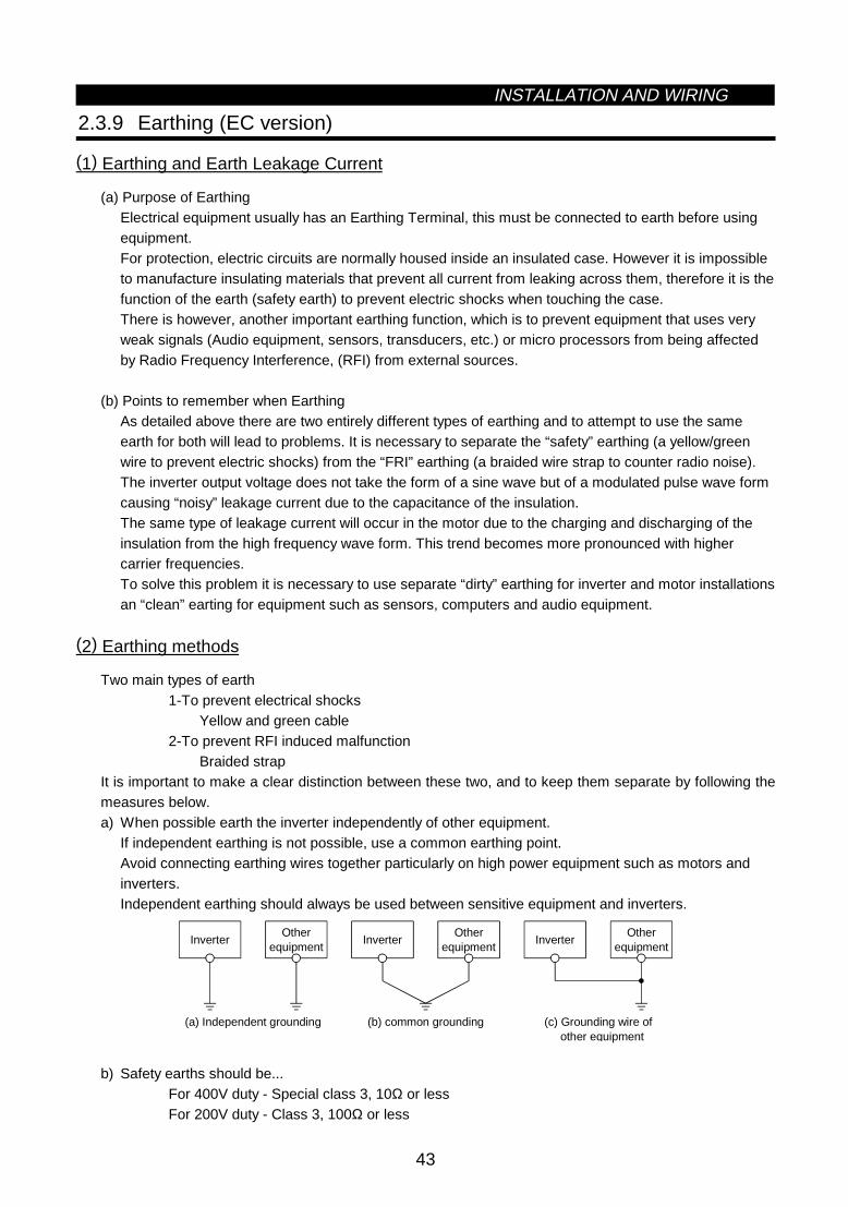
INSTALLATION AND WIRING
43
2.3.9 Earthing (EC version)
(1) Earthing and Earth Leakage Current
(a) Purpose of EarthingElectrical equipment usually has an Earthing Terminal, this must be connected to earth before usingequipment.For protection, electric circuits are normally housed inside an insulated case. However it is impossibleto manufacture insulating materials that prevent all current from leaking across them, therefore it is thefunction of the earth (safety earth) to prevent electric shocks when touching the case.There is however, another important earthing function, which is to prevent equipment that uses veryweak signals (Audio equipment, sensors, transducers, etc.) or micro processors from being affectedby Radio Frequency Interference, (RFI) from external sources.
(b) Points to remember when EarthingAs detailed above there are two entirely different types of earthing and to attempt to use the sameearth for both will lead to problems. It is necessary to separate the “safety” earthing (a yellow/greenwire to prevent electric shocks) from the “FRI” earthing (a braided wire strap to counter radio noise).The inverter output voltage does not take the form of a sine wave but of a modulated pulse wave formcausing “noisy” leakage current due to the capacitance of the insulation.The same type of leakage current will occur in the motor due to the charging and discharging of theinsulation from the high frequency wave form. This trend becomes more pronounced with highercarrier frequencies.To solve this problem it is necessary to use separate “dirty” earthing for inverter and motor installationsan “clean” earting for equipment such as sensors, computers and audio equipment.
(2) Earthing methods
Two main types of earth1-To prevent electrical shocks
Yellow and green cable2-To prevent RFI induced malfunction
Braided strapIt is important to make a clear distinction between these two, and to keep them separate by following themeasures below.a) When possible earth the inverter independently of other equipment.
If independent earthing is not possible, use a common earthing point.Avoid connecting earthing wires together particularly on high power equipment such as motors andinverters.Independent earthing should always be used between sensitive equipment and inverters.
Otherequipment
Inverter
(a) Independent grounding
Otherequipment
Inverter
(b) common grounding (c) Grounding wire of other equipment
Otherequipment
Inverter
b) Safety earths should be...For 400V duty - Special class 3, 10Ω or lessFor 200V duty - Class 3, 100Ω or less

INSTALLATION AND WIRING
44
c) The safety earth should be as thick as possible, minimum thickness as stated in below table.d) The earthing point should be as close to the inverter as possible, and the wire as short as possible.e) The RFI earth should be a braided strap with a 10mm
2 minimum cross sectional area, and as short as
possible.f) The earths should be as far away from input and output cables (particularly to equipment sensitive to
RFI) as possible, and any distance where they are parallel should be kept to a minimum.g) Design in RFI prevention before installation.
(Unit: mm2)
Earth Wire SizeMotor Size
400V Class3.7kW or less 25.5kW, 7.5kW 3.511kW to 15kW 8
18.5kW to 37kW 1445kW, 55kW 22

3
CHAPTER 3
OPERATION
This chapter provides the basic "operation" for use of thisproduct.Always read this chapter before using the equipment.
3.1 Pre-Operation Information........................................45 3.2 Operation .................................................................53
CHAPTER 1 OUTLINE
CHAPTER 2 INSTALLATION AND WIRING
CHAPTER 3 OPERATION
CHAPTER 4 PARAMETERS
CHAPTER 5 PROTECTIVE FUNCTIONS
CHAPTER 6 SPECIFICATIONS
CHAPTER 7 OPTIONS
APPENDICES

3.1 Pre-Operation InformationOPERATION
45
3 OPERATION3.1 Pre-Operation Information
3.1.1 Devices and parts to be prepared for operation
The inverter can be operated in any of the "external operation mode", "PU operation mode", "combinedoperation mode" and "communication operation mode". Prepare required instruments and parts according tothe operation mode.
(1) External operation mode (factory setting)
The inverter is operated under the control of externaloperation signals (frequency setting potentiometer,start switch, etc.) connected to the terminal block.With input power on, switch on the start signal (STF,STR) to start operation.
Preparation
· Start signal ..................................Switch, relay, etc.
DU04PU04
Potentiometer
Inverter
Start switch
· Frequency setting signal .............0 to 5V, 0 to 10V, 4 to 20mA DC signals from a potentiometer or outsidethe inverter
Note: 1. Both the start signal and frequency setting signal are required to run the inverter.
(2) PU operation mode
The inverter is operated from the keypad of the PU(FR-DU04/FR-PU04).This mode does not require the operation signals tobe connected and is useful for an immediate start ofoperation.
Preparation
DU04PU04
Inverter
· Operation unit..............................Operation panel (FR-DU04), parameter unit (FR-PU04)· Connection cable ........................To be prepared for use of the operation unit away from the inverter.
FR-CB2 (option) or the following connector and cable available on themarket:Connector : RJ45 connectorCable : Cable conforming to EIA568 (e.g. 10BASE-T cable)
(3) External/PU combined operation mode
The inverter is operated with the external operationand PU operation modes combined in any of thefollowing ways:1) The start signal is set with the external signal and
the frequency setting signal set from the PU; or2) The start signal is set with the run command key of
the PU (FR-DU04/FR-PU04) and the frequencysetting signal set with the external frequency settingpotentiometer.
3) Set "3" in Pr. 79 "operation mode selection".
PU PU
Potentiometer
Inverter
Start switch

OPERATION
46
Preparation
· Start signal ..................................Switch, relay, etc. (for 1)· Frequency setting signal .............0 to 5V, 0 to 10V, 4 to 20mA DC signals from a potentiometer or outside
the inverter (for 2)· Operation unit..............................Operation panel (FR-DU04), parameter unit (FR-PU04)· Connection cable ........................To be prepared for use of the operation unit away from the inverter
FR-CB2 (option) or the following connector and cable available on themarket:Connector : RJ45 connectorCable : Cable conforming to EIA568 (e.g. 10BASE-T cable)
3) Combined operation modeChange the setting of Pr. 79 "operation mode selection" as follows:
DescriptionSetting
Running frequency setting Start signal
3PU (FR-DU04/FR-PU04)· Direct setting and [UP/DOWN] key setting
Terminal signal· STF· STR
4
Terminal signal·0 to 5VDC across 2-5·0 to 10VDC across 2-5·4 to 20mADC across 4-5·Multi-speed selection (Pr. 4 to Pr. 6, Pr. 24
to Pr. 27, Pr. 232 to Pr. 239)·Jog frequency (Pr. 15)
Parameter unit· [FWD] key· [REV] key
(4) Communication operation mode
Communication operation can be performed by connecting a personal computer and the PU connector withthe RS-485 communication cable.The inverter setup software is available as an FR-A500 inverter start-up support software package.
Preparation
· Connection cable ........................Connector : RJ45 connectorCable : Cable conforming to EIA568
(e.g. 10BASE-T cable)· Personal computer
<Inverter setup software operating environment>
OS ................................................Windows 3.1, Windows 95 RAM.............................................. 1MB or more Floppy disk drive...........................One or more 3.5 inch floppy
disk drives Mouse...........................................Mouse connectable to the
personal computer

OPERATION
47
3.1.2 Power on
Before switching power on, check the following:
• Installation check
Make sure that the inverter is installed correctly in a correct place. (Refer to page 7.)· Wiring check
Make sure that the main and control circuits are wired correctly.Make sure that the options and peripheral devices are selected and connected correctly.(Refer to page 9.)
• Switch power on.
Power-on is complete when the POWER lamp is lit correctly and the operation panel (FR-DU04) displayscorrect data.
3.1.3 Parameter check
The inverter is designed to perform simple variable-speed operation with the factory settings of theparameters. Set the necessary parameters according to the load and operation specifications. Use theoperation panel (FR-DU04) to set, change and confirm the parameter values. For full information on theparameters, refer to "CHAPTER 4 PARAMETERS" (page 57).
(1) Operation panel (FR-DU04)
With the operation panel (FR-DU04), you can set the running frequency, monitor the operation commanddisplay, set parameters, display an error, and copy parameters.
1) Names and functions of the operation panel (FR-DU04)
DisplayLED ×4 digits
[MODE] key
[SET] key
Unit indication Hz (frequency) A (current) V (voltage)
Operation status indication
[Operation command] keys [REV] (reverse rotation) key [FWD] (forward rotation) key
[STOP/RESET] key
FR-DU04HzAV
MON EXT PU
CONTROL PANEL
FWD
MODE
SET
REV FWD
STOPRESET
REV
Key Description
[MODE] key You can select the operation mode or setting mode.
[SET] key You can determine the frequency and parameter setting.
[UP/DOWN] key( key)
· Used to increase or decrease the running frequency consecutively. Hold down this key to change thefrequency.
· Press this key in the setting mode to change the parameter setting consecutively.
[REV] key Used to give a reverse rotation command.
[FWD] key Used to give a forward rotation command.
[STOP/RESET] key· Used to stop operation.· Used to reset the inverter when its output is stopped by the protective function activated (major fault).

OPERATION
48
2) Monitor display changed by pressing the [MODE] key
MODE MODE MODE MODE
MODE
zHelp modezMonitoring mode zParameter setting mode zOperation mode
FR-DU04 CONTROL PANEL
Hz
MON EXT PU
AV
REV FWD
zFrequency setting mode (Note)
FR-DU04 CONTROL PANEL
Hz
MON EXT PU
AV
REV FWD
FR-DU04 CONTROL PANEL
Hz
MON EXT PU
AV
REV FWD
FR-DU04 CONTROL PANEL
Hz
MON EXT PU
AV
REV FWD
FR-DU04 CONTROL PANEL
Hz
MON EXT PU
AV
REV FWD
Note: The frequency setting mode is displayed only in the PU operation mode.
(2) Key operation
1) Monitoring mode· Operation command indications in the monitoring mode
EXT is lit to indicate external operation. PU is lit to indicate PU operation. Both EXT and PU are lit to indicate PU/external combined operation mode.
· The monitor display can also be changed during operation.
MODE
SET SET SET
SET
SETSET
*1
SET
*1
SET
*1
*2
To 2) Frequency setting mode (Note 3)
zFrequency monitor zCurrent monitor zVoltage monitor zAlarm monitor
Alarm present
Alarm absent
FR-DU04 CONTROL PANEL
Hz
MON EXT PU
AV
REV FWD
FR-DU04 CONTROL PANEL
Hz
MON EXT PU
AV
REV FWD
FR-DU04 CONTROL PANEL
Hz
MON EXT PU
AV
REV FWD
FR-DU04 CONTROL PANEL
Hz
MON EXT PU
AV
REV FWD
Note: 1. Hold down the [SET] key marked *1 for more than 1.5 seconds to change the current monitor tothe power-on monitor.
2. Hold down the [SET] key marked *2 for more than 1.5 seconds to display four errors including themost recent one.
3. Shifts to the parameter setting mode when in the external operation mode.
2) Frequency setting mode· Used to set the running frequency in the PU operation mode.
MODE
SET
MODE
To 3) Parameter setting mode
zSet frequency writezSet frequency change
Press to change the set frequency.
To frequency monitor
FR-DU04 CONTROL PANEL
Hz
MON EXT PU
AV
REV FWD
FR-DU04 CONTROL PANEL
Hz
MON EXT PU
AV
REV FWD
FR-DU04 CONTROL PANEL
Hz
MON EXT PU
AV
REV FWD

OPERATION
49
3) Parameter setting mode· A parameter value may either be set by updating its parameter number or setting the value digit-by-digit
using the [UP/DOWN] key.· To write the setting, change it and press the [SET] key 1.5 seconds.
Set "0" or "4" (factory setting) in Pr. 79 "operation mode selection" or select the PU operation mode.
MODE SET
SET SET
SET SET
MODE
SET
0 ∼ 9 0 ∼ 9 0 ∼ 9
SET
To 4) Operation mode
zParameter number change zSetting changePress for1.5 sec.
zSetting writeFlicker
Press
to change the setting.
Simultaneous input
Most significant digit flickers Middle digit flickers Least significant digit flickerszhanging the parameter number
to change the parameter number.
Press
FR-DU04 CONTROL PANEL
Hz
MON EXT PU
AV
REV FWD
FR-DU04 CONTROL PANEL
Hz
MON EXT PU
AV
REV FWD
FR-DU04 CONTROL PANEL
Hz
MON EXT PU
AV
REV FWD
FR-DU04 CONTROL PANEL
Hz
MON EXT PU
AV
REV FWD
FR-DU04 CONTROL PANEL
Hz
MON EXT PU
AV
REV FWD
FR-DU04 CONTROL PANEL
Hz
MON EXT PU
AV
REV FWD
FR-DU04 CONTROL PANEL
Hz
MON EXT PU
AV
REV FWD
FR-DU04 CONTROL PANEL
Hz
MON EXT PU
AV
REV FWD
FR-DU04 CONTROL PANEL
Hz
MON EXT PU
AV
REV FWD
FR-DU04 CONTROL PANEL
Hz
MON EXT PU
AV
REV FWD
FR-DU04 CONTROL PANEL
Hz
MON EXT PU
AV
REV FWD
4) Operation mode
MODE MODEMODE
To 5) Help mode
zExternal operation zPU operation zPU jog operation
FR-DU04 CONTROL PANEL
Hz
MON EXT PU
AV
REV FWD
FR-DU04 CONTROL PANEL
Hz
MON EXT PU
AV
REV FWD
FR-DU04 CONTROL PANEL
Hz
MON EXT PU
AV
REV FWD
5) Help mode
MODE
To 1) Monitoring mode
zAlarm history zAlarm history clear
zParameter clear zAll clear zUser clear zSoftware version readFR-DU04 CONTROL PANEL
Hz
MON EXT PU
AV
REV FWD

OPERATION
50
· Alarm history Four past alarms can be displayed with the [UP/DOWN] key. ("." is appended to the most recent alarm.)
E.HIS SET
Shows an alarm. (When no alarm exists, E._ _0 is displayed.)
Alarm display SET
Frequency at alarm occurrence is displayed.
· Alarm history clearClears all alarm history.
SET SET
SET
Flicker
Cancel
FR-DU04 CONTROL PANEL
Hz
MON EXT PU
AV
REV FWD
FR-DU04 CONTROL PANEL
Hz
MON EXT PU
AV
REV FWD
FR-DU04 CONTROL PANEL
Hz
MON EXT PU
AV
REV FWD
FR-DU04 CONTROL PANEL
Hz
MON EXT PU
AV
REV FWD
· Parameter clearInitialises the parameter values to the factory settings. The calibration values are not initialized.(Parameter values are not cleared by setting "1" in Pr. 77 "parameter write disable selection).)
SET SET
SET
Flicker
Cancel
FR-DU04 CONTROL PANEL
Hz
MON EXT PU
AV
REV FWD
FR-DU04 CONTROL PANEL
Hz
MON EXT PU
AV
REV FWD
FR-DU04 CONTROL PANEL
Hz
MON EXT PU
AV
REV FWD
FR-DU04 CONTROL PANEL
Hz
MON EXT PU
AV
REV FWD
· All clearInitialises the parameter values and calibration values to the factory settings.
SET SET
SET
Flicker
Cancel
FR-DU04 CONTROL PANEL
Hz
MON EXT PU
AV
REV FWD
FR-DU04 CONTROL PANEL
Hz
MON EXT PU
AV
REV FWD
FR-DU04 CONTROL PANEL
Hz
MON EXT PU
AV
REV FWD
FR-DU04 CONTROL PANEL
Hz
MON EXT PU
AV
REV FWD
· User clearInitialises the user-set parameters.The other parameters are initialized to the factory settings.
SET SET
SET
Flicker
Cancel
FR-DU04 CONTROL PANEL
Hz
MON EXT PU
AV
REV FWD
FR-DU04 CONTROL PANEL
Hz
MON EXT PU
AV
REV FWD
FR-DU04 CONTROL PANEL
Hz
MON EXT PU
AV
REV FWD
FR-DU04 CONTROL PANEL
Hz
MON EXT PU
AV
REV FWD

OPERATION
51
6) Copy modeBy using the operation panel (FR-DU04), the parameter values can be copied to another inverter (only theFR-A500 series).1) Operation procedure
After reading the parameter values from the copy source inverter, connect the operation panel to thecopy destination inverter, and write the parameter values.After writing the parameters to the inverter of copy destination, always reset the inverter, e.g. switchpower off once, before starting operation.
SET SET SET
SET
Connect to copy destination inverter.
zParameter setting mode
(Note 1) (Note 1) (Note 1)
zParameter read zParameter write zParameter verify
Press for 1.5 sec.
Press for 1.5 sec.
Press for 1.5 sec.
FR-DU04 CONTROL PANEL
Hz
MON EXT PU
AV
REV FWD
FR-DU04 CONTROL PANEL
Hz
MON EXT PU
AV
REV FWD
FR-DU04 CONTROL PANEL
Hz
MON EXT PU
AV
REV FWD
FR-DU04 CONTROL PANEL
Hz
MON EXT PU
AV
REV FWD
FR-DU04 CONTROL PANEL
Hz
MON EXT PU
AV
REV FWD
FR-DU04 CONTROL PANEL
Hz
MON EXT PU
AV
REV FWD
FR-DU04 CONTROL PANEL
Hz
MON EXT PU
AV
REV FWD
FR-DU04 CONTROL PANEL
Hz
MON EXT PU
AV
REV FWD
FR-DU04 CONTROL PANEL
Hz
MON EXT PU
AV
REV FWD
After writing the parameters, always reset the inverter before operation.
Note: 1. While the copy function is being activated, the monitor display flickers. The display returns to thelit-up state on completion of the copy function.
2. If a read error occurs during parameter read, "read error (E.rE1)" is displayed.3. If a write error occurs during parameter write, "write error (E.rE2)" is displayed.4. If a data discrepancy occurs during parameter verify, the corresponding parameter number and
"verify error (E.rE3)" are displayed alternately. If the direct frequency setting or jog frequencysetting is discrepant, "verify error (E.rE3)" flickers. To ignore this display and continue verify,press the [SET] key.
5. When the copy destination inverter is not the FR-A500 series, "model error (E.rE4)" is displayed.
Reference: It is recommended to read the parameter values after completion of parameter setting.By writing the parameter values from the operation panel fitted to a new inverter after inverterreplacement, parameter setup can be completed.

OPERATION
52
(3) Parameter setting check
We recommend the following parameters to be set by the user.Set them according to the operation specifications, load, etc. (Refer to page 57.)
ParameterNumber
Name Application
1 Maximum frequency2 Minimum frequency
Used to set the maximum and minimum output frequencies.
7 Acceleration time8 Deceleration time
44Second acceleration/decelerationtime
45 Second deceleration time
110Third acceleration/decelerationtime
111 Third deceleration time
Used to set the acceleration and deceleration times.
9 Electronic thermal O/L relayUsed to set the current of the electronic overcurrent protection to protectthe motor from overheat.
14 Load pattern selectionUsed to select the optimum output characteristics which match theapplication and load characteristics.
71 Applied motorUsed to set the thermal characteristics of the electronic overcurrentprotection according to the motor used.
73 0-5V/0-10V selectionUsed to select the specifications of the frequency setting signal enteredacross terminal 2-5 to perform operation with the voltage input signal.
900 FM terminal calibration901 AM terminal calibration
Used to calibrate the meters connected across terminals FM-SD and AM-5.
902 Frequency setting voltage bias903 Frequency setting voltage gain904 Frequency setting current bias905 Frequency setting current gain
Used to set the magnitude (slope) of the output frequency relative to thefrequency setting signal (0 to 5V, 0 to 10V or 4 to 20mA DC) as desired.

3.2 OperationOPERATION
53
3.2 Operation
3.2.1 Pre-operation checks
Before starting operation, check the following:
• SafetyPerform test operation after making sure that safety is ensured if the machine should become out ofcontrol.
• MachineMake sure that the machine is free of damage.
• ParametersSet the parameter values to match the operating machine system environment.
• Test operationPerform test operation and make sure that the machine operates safely under light load at a low frequency.After that, start operation.

OPERATION
54
3.2.2 External operation mode (Operation using external input signals)
(1) Operation at 60Hz
Step Description Image
1
Power-on → Operation mode checkSwitch power on and make sure that the operation commandindication "EXT" is lit.(If it is not lit, switch to the external operation mode.)
ON
FR-DU04 CONTROL PANEL
Hz
MON EXT PU
AV
REV FWD
2
StartTurn on the start switch (STF or STR).The operation status indication "FWD" or "REV" flickers.
Note: The motor does not start if both the forward and reverserotation switches are turned on.If both switches are turned on during operation, the motordecelerates to a stop.
Reverserotation
Forwardrotation
FR-DU04 CONTROL PANEL
Hz
MON EXT PU
AV
REV FWD
3
Acceleration → Constant speedSlowly turn the potentiometer (frequency setting potentiometer) fullclockwise.The frequency shown on the display increases gradually to 60.00Hz.
FR-DU04 CONTROL PANEL
Hz
MON EXT PU
AV
REV FWD
4
DecelerationSlowly turn the potentiometer (frequency setting potentiometer) fullcounterclockwise.The frequency shown on the display decreases gradually to 0.00Hz.The motor stops running. REV FWD
5
StopTurn off the start switch (STF or STR).
OFF
Stop
Forwardrotation
Reverserotation
(2) External jog operation
Keep the start switch (STF or STR) on to perform operation, and switch it off to stop.1) Set Pr. 15 "jog frequency" and Pr. 16 "jog acceleration/deceleration".2) Select the external operation mode.3) Switch on the jog signal. Keep the start switch (STF or STR) on to perform operation.

OPERATION
55
3.2.3 PU operation mode(Operation using the operation panel (FR-DU04))
(1) Operation at 60Hz
While the motor is running, repeat the following steps 2 and 3 to vary the speed:
Step Description Image
1
Power-on → Operation mode checkSwitch power on and make sure that the operation commandindication "PU" is lit.(If it is not lit, switch to the PU operation mode.)
ON
REV FWD
2
Running frequency settingSet the running frequency to 60Hz.First, press the [MODE] key to select the frequency setting mode.Then, press the [UP/DOWN] key to change the setting, and pressthe [SET] key to write the frequency.
(or)
FR-DU04 CONTROL PANEL
Hz
MON EXT PU
AV
REV FWD
3
StartPress the [FWD] or [REV] key.The motor starts running. The monitoring mode is automaticallyselected and the output frequency is displayed.
REVFWD (or)
REV FWD
4
StopPress the [STOP] key.The motor is decelerated to a stop.
FR-DU04 CONTROL PANEL
Hz
MON EXT PU
AV
REV FWD
(2) PU jog operation
Hold down the [FWD] or [REV] key to perform operation, and release it to stop.
1) Set Pr. 15 "jog frequency" and Pr. 16 "jog acceleration/deceleration".2) Select the PU jog operation mode.3) Hold down the [FWD] or [REV] key to perform operation.
(If the motor remains stopped, check Pr. 13 "starting frequency". The motor will not start if its setting islower than the starting frequency.)

OPERATION
56
3.2.4 Combined operation mode(Operation using the external input signals and PU)
When entering the start signal from outside the inverter and setting the running frequency from the PU(Pr. 79 = 3)The external frequency setting signals and the PU's FWD, REV and STOP keys are not accepted.
Step Description Image
1
Power-onSwitch power on.
ON
2
Operation mode selectionSet "3" in Pr. 79 "operation mode selection".The combined operation mode is selected and the operation statusindication "EXT" and "PU" are lit.
FR-DU04 CONTROL PANEL
Hz
MON EXT PU
AV
REV FWD
3
StartTurn on the start switch (STF or STR).
Note: The motor does not start if both the forward and reverserotation switches are turned on. If both switches areturned on during operation, the motor decelerates (whenPr. 250 = "9999") to a stop.
ON
Reverserotation
Forwardrotation
FR-DU04 CONTROL PANEL
Hz
MON EXT PU
AV
REV FWD
4
Running frequency settingUsing the parameter unit, set the running frequency to 60Hz.The operation command indication "REV" or "FWD" is lit.· Select the frequency setting mode and make step setting.
Note: Step setting is the way of changing the frequencyconsecutively by pressing the [UP/DOWN] key.Hold down the [UP/DOWN] key to change the frequency.
<Step setting>
5
StopTurn off the start switch (STF or STR).The motor stops running.
FR-DU04 CONTROL PANEL
Hz
MON EXT PU
AV
REV FWD

4
CHAPTER 4
PARAMETERS
This chapter explains the "parameters" of this product.Always read the instructions before using the equipment.
4.1 Parameter List .........................................................57 4.2 Parameter Function Details......................................63
Note: By making parameter settings, you can change the functions of contact inputterminals RL, RM, RH, RT, AU, JOG, CS and open collector output terminalsRUN, SU, IPF, OL, FU. Therefore, signal names corresponding to the functionsare used in the description of this chapter (except in the wiring examples). Notethat they are not terminal names.Note: The settings in brackets refer to the “EC” version default settings.
CHAPTER 1 OUTLINE
CHAPTER 2 INSTALLATION AND WIRING
CHAPTER 3 OPERATION
CHAPTER 4 PARAMETERS
CHAPTER 5 PROTECTIVE FUNCTIONS
CHAPTER 6 SPECIFICATIONS
CHAPTER 7 OPTIONS
APPENDICES

4.1 Parameter List PARAMETERS
57
4 PARAMETER4.1 Parameter List
Func-tion
ParameterNumber
Name Setting RangeMinimumSetting
Increments
Factory Setting⟨EC Version⟩
ReferTo
Page:
0 Torque boost (Note 1) 0 to 30% 0.1%6%/4%/3%/2%
(Note 9)63
1 Maximum frequency 0 to 120Hz 0.01Hz 120Hz 642 Minimum frequency 0 to 120Hz 0.01Hz 0Hz 643 Base frequency 0 to 400Hz 0.01Hz 60Hz ⟨50Hz⟩ 654 Multi-speed setting (high speed) 0 to 400Hz 0.01Hz 60Hz 665 Multi-speed setting (middle speed) 0 to 400Hz 0.01Hz 30Hz 666 Multi-speed setting (low speed) 0 to 400Hz 0.01Hz 10Hz 66
7 Acceleration time0 to 3600 s/0 to 360 s
0.1 s/0.01 s
5 s/15 s(Note 6)
67
8 Deceleration time0 to 3600 s/0 to 360 s
0.1 s/0.01 s
5 s/15 s(Note 6)
67
Bas
ic fu
nctio
ns
9 Electronic thermal O/L relay 0 to 500A 0.01ARated output
current68
10 DC injection brake operation frequency 0 to 120Hz, 9999 0.01Hz 3Hz 6911 DC injection brake operation time 0 to 10 s, 8888 0.1 s 0.5 s 6912 DC injection brake voltage 0 to 30% 0.1% 4%/2% (Note 6) 6913 Starting frequency 0 to 60Hz 0.01Hz 0.5Hz 7014 Load pattern selection (Note 1) 0 to 5 1 0 7015 Jog frequency 0 to 400Hz 0.01Hz 5Hz 71
16 Jog acceleration/deceleration time0 to 3600 s/0 to 360 s
0.1 s/0.01 s
0.5 s 71
17 MRS input selection 0,2 1 0 7218 High-speed maximum frequency 120 to 400Hz 0.01Hz 120Hz 7219 Base frequency voltage (Note 1) 0 to 1000V, 8888, 9999 0.1V 9999 ⟨8888⟩ 72
20Acceleration/deceleration referencefrequency
1 to 400Hz 0.01Hz 60Hz ⟨50Hz⟩ 72
21Acceleration/deceleration timeincrements
0,1 1 0 72
22 Stall prevention operation level 0 to 200%, 9999 0.1% 150% 73
23Stall prevention operation level at doublespeed
0 to 200%, 9999 0.1% 9999 73
24 Multi-speed setting (speed 4) 0 to 400Hz, 9999 0.01Hz 9999 7425 Multi-speed setting (speed 5) 0 to 400Hz, 9999 0.01Hz 9999 7426 Multi-speed setting (speed 6) 0 to 400Hz, 9999 0.01Hz 9999 7427 Multi-speed setting (speed 7) 0 to 400Hz, 9999 0.01Hz 9999 7428 Multi-speed input compensation 0, 1 1 0 7429 Acceleration/deceleration pattern 0, 1, 2, 3 1 0 7530 Regenerative function selection 0, 1, 2 1 0 7631 Frequency jump 1A 0 to 400Hz, 9999 0.01Hz 9999 7732 Frequency jump 1B 0 to 400Hz, 9999 0.01Hz 9999 7733 Frequency jump 2A 0 to 400Hz, 9999 0.01Hz 9999 7734 Frequency jump 2B 0 to 400Hz, 9999 0.01Hz 9999 7735 Frequency jump 3A 0 to 400Hz, 9999 0.01Hz 9999 7736 Frequency jump 3B 0 to 400Hz, 9999 0.01Hz 9999 77
Sta
ndar
d op
erat
ion
func
tions
37 Speed display 0,1 to 9998 1 0 78
41 Up-to-frequency sensitivity 0 to 100% 0.1% 10% 79
42 Output frequency detection 0 to 400Hz 0.01Hz 6Hz 79
Out
put
term
inal
func
tions
43Output frequency detection for reverserotation
0 to 400Hz, 9999 0.01Hz 9999 79
44 Second acceleration/deceleration time0 to 3600 s/0 to 360 s
0.1 s/0.01 s 5 s 80
45 Second deceleration time0 to 3600 s/0 to 360 s,
99990.1 s/0.01 s 9999 80
46 Second torque boost (Note 1) 0 to 30%, 9999 0.1% 9999 8047 Second V/F (base frequency) (Note 1) 0 to 400Hz, 9999 0.01Hz 9999 8048 Second stall prevention operation current 0 to 200% 0.1% 150% 80
49Second stall prevention operationfrequency
0 to 400Hz, 9999 0.01 0 80
Sec
ond
func
tions
50 Second output frequency detection 0 to 400Hz 0.01Hz 30Hz 81
Pa
ram
ete
r L
ist

PARAMETERS
58
Func-tion
ParameterNumber
Name Setting RangeMinimumSetting
Increments
Factory Setting⟨EC Version⟩
ReferTo
Page:
52 DU/PU main display data selection0 to 20, 22, 23, 24, 25,
1001 0 82
53 PU level display data selection 0 to 3, 5 to 14, 17, 18 1 1 82
54 FM terminal function selection1 to 3, 5 to 14,
17, 18, 211 1 82
55 Frequency monitoring reference 0 to 400Hz 0.01Hz 60Hz ⟨50Hz⟩ 84
Dis
play
func
tions
56 Current monitoring reference 0 to 500A 0.01A Rated output current 84
57 Restart coasting time 0, 0.1 to 5 s, 9999 0.1 s 9999 85
Aut
omat
icre
star
tfu
nctio
ns
58 Restart cushion time 0 to 60 s 0.1 s 1.0 s 85
Add
ition
alfu
nctio
n
59 Remote setting function selection 0, 1, 2 1 0 87
60 Intelligent mode selection 0 to 8 1 0 8861 Reference I for intelligent mode 0 to 500A, 9999 0.01A 9999 9062 Ref. I for intelligent mode accel. 0 to 200%, 9999 0.1% 9999 9063 Ref. I for intelligent mode decel. 0 to 200%, 9999 0.1% 9999 9064 Starting frequency for elevator mode 0 to 10Hz, 9999 0.01Hz 9999 9065 Retry selection 0 to 5 1 0 91
66Stall prevention operation level reductionstarting frequency
0 to 400Hz 0.01Hz 60Hz ⟨50Hz⟩ 92
67 Number of retries at alarm occurrence 0 to 10,101 to 110 1 0 9168 Retry waiting time 0 to 10 s 0.1 s 1 s 9169 Retry count display erasure 0 0 91
70 Special regenerative brake duty0 to 15%/0 to 30%/0%
(Note 10)0.1% 0% 92
71 Applied motor0 to 8, 13 to 18, 20, 23,
241 0 93
72 PWM frequency selection 0 to 15 1 2 9473 0-5V/0-10V selection 0 to 5, 10 to 15 1 1 9574 Filter time constant 0 to 8 1 1 96
75Reset selection/disconnected PUdetection/PU stop selection
0 to 3, 14 to 17 1 14 96
76 Alarm code output selection 0, 1, 2, 3 1 0 9877 Parameter write disable selection 0, 1, 2 1 0 9978 Reverse rotation prevention selection 0, 1, 1 0 100
Ope
ratio
n se
lect
ion
func
tions
79 Operation mode selection 0 to 8 1 0 10180 Motor capacity 0.4 to 55kW, 9999 0.01kW 9999 10481 Number of motor poles 2, 4, 6, 12, 14, 16, 9999 1 9999 10482 Motor exciting current (Note 4) 0 to , 9999 1 9999 10583 Rated motor voltage 0 to 1000V 0.1V 200/400V (Note 2) 10584 Rated motor frequency 50 to 120Hz 0.01Hz 60Hz ⟨50Hz⟩ 10589 Speed control gain 0 to 200.0% 0.1% 100% 11190 Motor constant (R1) (Note 4) 0 to, 9999 9999 10591 Motor constant (R2) (Note 4) 0 to, 9999 9999 10592 Motor constant (L1) (Note 4) 0 to, 9999 9999 10593 Motor constant (L2) (Note 4) 0 to, 9999 9999 10594 Motor constant (X) 0 to, 9999 9999 10595 Online auto tuning selection 0, 1 1 0 111
Adv
ance
d m
agne
tic fl
ux v
ecto
rcon
trol
96 Auto tuning setting/status 0, 1, 101 1 0 112100 V/F1 (first frequency) (Note 1) 0 to 400Hz, 9999 0.01Hz 9999 113101 V/F1 (first frequency voltage) (Note 1) 0 to 1000V 0.1V 0 113102 V/F2 (second frequency) (Note 1) 0 to 400Hz, 9999 0.01Hz 9999 113103 V/F2 (second frequency voltage) (Note 1) 0 to 1000V 0.1V 0 113104 V/F3 (third frequency) (Note 1) 0 to 400Hz, 9999 0.01Hz 9999 113105 V/F3 (third frequency voltage) (Note 1) 0 to 1000V 0.1V 0 113
5-po
int f
lexi
ble
V/F
char
acte
ristic
s
106 V/F4 (fourth frequency) (Note 1) 0 to 400Hz, 9999 0.01Hz 9999 113
Pa
ram
ete
r L
ist

PARAMETERS
59
Func-tion
ParameterNumber
Name Setting RangeMinimumSetting
Increments
Factory Setting⟨EC Version⟩
ReferTo
Page:
107V/F4 (fourth frequency voltage)(Note 1)
0 to 1000V 0.1V 0 113
108 V/F5 (fifth frequency) (Note 1) 0 to 400Hz, 9999 0.01Hz 9999 113
5-po
int f
lexi
ble
V/F
char
acte
ristic
s
109V/F5 (fifth frequency voltage)(Note 1)
0 to 1000V 0.1V 0 113
110 Third acceleration/deceleration time0 to 3600 s/0 to 360 s,
99990.1 s/0.01 s 9999 114
111 Third deceleration time0 to 3600 s/0 to 360 s,
99990.1 s/0.01 s 9999 114
112 Third torque boost (Note 1) 0 to 30.0%, 9999 0.1% 9999 114113 Third V/F (base frequency) (Note 1) 0 to 400Hz, 9999 0.01Hz 9999 114114 Third stall prevention operation current 0 to 200% 0.1% 150% 114
115Third stall prevention operationfrequency
0 to 400Hz 0.01Hz 0 114
Thi
rd fu
nctio
ns
116 Third output frequency detection 0 to 400Hz, 9999 0.01Hz 9999 114117 Station number 0 to 31 1 0 114118 Communication speed 48, 96, 192 1 192 114
119 Stop bit length/data length0, 1 (data length 8)
10, 11 (data length 7)1 1 114
120 Parity check presence/absence 0, 1, 2 1 2 114121 Number of communication retries 0 to 10, 9999 1 1 114122 Communication check time interval 0, 0.1 to 999.8 s, 9999 0.1 s 0 ⟨9999⟩ 114123 Waiting time setting 0 to 150ms, 9999 1ms 9999 114
Com
mun
icat
ion
func
tions
124 CR, LF presence/absence selection 0,1,2 1 1 114128 PID action selection 10, 11, 20, 21 10 124129 PID proportional band 0.1 to 1000%, 9999 0.1% 100% 124130 PID integral time 0.1 to 3600 s, 9999 0.1 s 1 s 124131 Upper limit 0 to 100%, 9999 0.1% 9999 124132 Lower limit 0 to 100%, 9999 0.1% 9999 124133 PID action set point for PU operation 0 to 100% 0.01% 0% 124
PID
con
trol
134 PID differential time 0.01 to 10.00 s, 9999 0.01 s 9999 124
135Commercial power supply-inverterswitch-over sequence output terminalselection
0, 1 1 0 131
136 MC switch-over interlock time 0 to 100.0 s 0.1 s 1.0 s 131137 Start waiting time 0 to 100.0 s 0.1 s 0.5 s 131
138Commercial power supply-inverterswitch-over selection at alarmoccurrence
0, 1 1 0 131
Com
mer
cial
pow
er s
uppl
y-in
vert
er s
witc
h-ov
er
139Automatic inverter-commercial powersupply switch-over frequency
0 to 60.00Hz, 9999 0.01Hz 9999 131
140Backlash acceleration stoppingfrequency (Note 7)
0 to 400Hz 0.01Hz 1.00Hz 134
141Backlash acceleration stopping time(Note 7)
0 to 360 s 0.1 s 0.5 s 134
142Backlash deceleration stoppingfrequency (Note 7)
0 to 400Hz 0.01Hz 1.00Hz 134Bac
klas
h
143Backlash deceleration stopping time(Note 7)
0 to 360 s 0.1 s 0.5 s 134
Dis
play
144 Speed setting switch-over0, 2, 4, 6, 8, 10, 102,104, 106, 108, 110
1 4 134
148 Stall prevention level at 0V input 0 to 200% 0.1% 150% 134
Add
ition
alfu
nctio
ns
149 Stall prevention level at 10V input 0 to 200% 0.1% 200% 134
Pa
ram
ete
r L
ist

PARAMETERS
60
Func-tion
ParameterNumber
Name Setting RangeMinimumSetting
Increments
Factory Setting⟨EC Version⟩
ReferTo
Page:
150 Output current detection level 0 to 200% 0.1% 150% 135
151 Output current detection period 0 to 10 s 0.1 s 0 135
152 Zero current detection level 0 to 200.0% 0.1% 5.0% 136Cur
rent
dete
ctio
n
153 Zero current detection period 0 to 1 s 0.01 s 0.5 s 136
154Voltage reduction selection during stallprevention operation
0, 1 1 1 136
155 RT activated condition 0, 10 1 0 137156 Stall prevention operation selection 0 to 31, 100 1 0 137157 OL signal waiting time 0 to 25 s, 9999 0.1 s 0 139
Sub
func
tions
158 AM terminal function selection1 to 3, 5 to 14,
17, 18, 211 1 139
Add
ition
alfu
nctio
n
160 User group read selection 0, 1, 10, 11 1 0 140
162Automatic restart after instantaneouspower failure selection
0, 1 1 0 140
163 First cushion time for restart 0 to 20 s 0.1 s 0 s 140
164 First cushion voltage for restart 0 to 100% 0.1% 0% 140
Aut
omat
ic r
esta
rtaf
ter
inst
anta
neou
spo
wer
failu
re
165 Restart stall prevention operation level 0 to 200% 0.1% 150% 140
170 Watt-hour meter clear 0 0 141
Initi
alm
onito
r
171 Actual operation hour meter clear 0 0 141
173 User group 1 registration 0 to 999 1 0 141
174 User group 1 deletion 0 to 999, 9999 1 0 141
175 User group 2 registration 0 to 999 1 0 141
Use
r fu
nctio
ns
176 User group 2 deletion 0 to 999, 9999 1 0 141
180 RL terminal function selection 0 to 99, 9999 1 0 141181 RM terminal function selection 0 to 99, 9999 1 1 141182 RH terminal function selection 0 to 99, 9999 1 2 141183 RT terminal function selection 0 to 99, 9999 1 3 141184 AU terminal function selection 0 to 99, 9999 1 4 141185 JOG terminal function selection 0 to 99, 9999 1 5 141186 CS terminal function selection 0 to 99, 9999 1 6 141190 RUN terminal function selection 0 to 199, 9999 1 0 144191 SU terminal function selection 0 to 199, 9999 1 1 144192 IPF terminal function selection 0 to 199, 9999 1 2 144193 OL terminal function selection 0 to 199, 9999 1 3 144194 FU terminal function selection 0 to 199, 9999 1 4 144
Ter
min
al a
ssig
nmen
t fun
ctio
ns
195 ABC terminal function selection 0 to 199, 9999 1 99 144
Add
iti-
onal
func
tion
199 User's initial value setting 0 to 999, 9999 1 0 146
Pa
ram
ete
r L
ist

PARAMETERS
61
Func-tion
ParameterNumber
Name Setting RangeMinimumSetting
Increments
Factory Setting⟨EC Version⟩
ReferTo
Page:
200Programmed operation minute/secondselection
0, 2: Minute, second1, 3: Hour, minute
1 0 147
201Program set 11 to 10
0-2: Rotation direction0-400, 9999: Frequency0-99.59: Time
10.1Hz
Minute orsecond
09999
0147
211Program set 211 to 20
0-2: Rotation direction0-400, 9999: Frequency0-99.59: Time
10.1Hz
Minute orsecond
09999
0147
221Program set 321 to 30
0-2: Rotation direction0-400, 9999: Frequency0-99.59: Time
10.1Hz
Minute orsecond
09999
0147
Pro
gram
med
ope
ratio
n
231 Timer setting 0 to 99.59 0 147232 Multi-speed setting (speed 8) 0 to 400Hz, 9999 0.01Hz 9999 151233 Multi-speed setting (speed 9) 0 to 400Hz, 9999 0.01Hz 9999 151234 Multi-speed setting (speed 10) 0 to 400Hz, 9999 0.01Hz 9999 151235 Multi-speed setting (speed 11) 0 to 400Hz, 9999 0.01Hz 9999 151236 Multi-speed setting (speed 12) 0 to 400Hz, 9999 0.01Hz 9999 151237 Multi-speed setting (speed 13) 0 to 400Hz, 9999 0.01Hz 9999 151238 Multi-speed setting (speed 14) 0 to 400Hz, 9999 0.01Hz 9999 151
Mul
ti-sp
eed
oper
atio
n
239 Multi-speed setting (speed 15) 0 to 400Hz, 9999 0.01Hz 9999 151
240 Soft-PWM setting 0, 1 1 1 151
Sub
func
tions
244 Cooling fan operation selection 0, 1 1 0 151
Sto
p se
lect
ion
func
tion
250 Stop selection 0 to 100 s, 9999 0.1 s 9999 152
251 Output phase failure protection selection 0,1 1 1 153
252 Override bias 0 to 200% 0.1% 50% 153
Add
ition
alfu
nctio
n
253 Override gain 0 to 200% 0.1% 150% 153261 Power failure stop selection 0, 1 1 0 154
262Subtracted frequency at decelerationstart
0 to 20Hz 0.01Hz 3Hz 154
263 Subtraction starting frequency 0 to 120Hz, 9999 0.01Hz 60Hz ⟨50Hz⟩ 154264 Power-failure deceleration time 1 0 to 3600/0 to 360 s 0.1 s/0.01 s 5 s 154
265 Power-failure deceleration time 20 to 3600/0 to 360 s,
99990.1 s/0.01 s 9999 154
Pow
er fa
ilure
sto
p fu
nctio
n
266Power-failure deceleration time switch-over frequency
0 to 400Hz 0.01Hz 60Hz ⟨50Hz⟩ 154
Sel
ectio
nfu
nctio
n
270Stop-on-contact/load torque high-speedfrequency control selection
0, 1, 2, 3 1 0 156
271 High-speed setting maximum current 0 to 200% 0.1% 50% 157
272 Mid-speed setting minimum current 0 to 200% 0.1% 100% 157
273 Current averaging range 0 to 400Hz, 9999 0.01Hz 9999 157
Hig
h-sp
eed
freq
uenc
yco
ntro
l
274 Current averaging filter constant 1 to 4000 1 16 157
275Stop-on-contact exciting current low-speed multiplying factor
0 to 1000%, 9999 1% 9999 (Note 5) 161
Sto
p on
cont
act
276 Stop-on-contact PWM carrier frequency 0 to 15, 9999 1 9999 (Note 5) 161
Pa
ram
ete
r L
ist

PARAMETERS
62
Func-tion
ParameterNumber
Name Setting RangeMinimumSetting
Increments
Factory Setting⟨EC Version⟩
ReferTo
Page:278 Brake opening frequency (Note 3) 0 to 30Hz 0.01Hz 3Hz 164279 Brake opening current (Note 3) 0 to 200% 0.1% 130% 164
280Brake opening current detection time(Note 3)
0 to 2 s 0.1 s 0.3 s 164
281 Brake operation time at start (Note 3) 0 to 5 s 0.1 s 0.3 s 164282 Brake operation frequency (Note 3) 0 to 30Hz 0.01Hz 6Hz 164283 Brake operation time at stop (Note 3) 0 to 5 s 0.1 s 0.3 s 164
284Deceleration detection function selection(Note 3)
0, 1 1 0 164
285 Overspeed detection frequency 0 to 30Hz, 9999 0.01Hz 9999 164286 Droop gain 0 to 100% 0.1% 0% 168
Bra
ke s
eque
nce
func
tions
287 Droop filler constant 0.00 to 1.00 s 0.01s 0.3s 168900 FM terminal calibration 169901 AM terminal calibration 169902 Frequency setting voltage bias 0 to 10V 0 to 60Hz 0.01Hz 0V 0Hz 171
903 Frequency setting voltage gain 0 to 10V1 to
400Hz0.01Hz 5V
60Hz ⟨50Hz⟩
171
904 Frequency setting current bias 0 to 20mA 0 to 60Hz 0.01Hz 4mA 0Hz 171
Cal
ibra
tion
func
tions
905 Frequency setting current gain 0 to 20mA1 to
400Hz0.01Hz 20mA
60Hz⟨50Hz⟩
171
Add
ition
alfu
nctio
n
990 Buzzer control 0, 1 1 1 173
Note: 1. Indicates the parameter settings which are ignored when the advanced magnetic flux vectorcontrol mode is selected.
2. The factory setting of the FR-A540 (400V class) is 400V.3. Can be set when Pr. 80, Pr. 81 ≠ 9999, Pr. 60 = 7 or 8.4. Can be accessed when Pr. 80, Pr. 81 ≠ 9999, Pr. 77 = 801.5. Can be accessed when Pr. 270 = 1 or 3, Pr. 80, Pr. 81 ≠ 9999.6. The setting depends on the inverter capacity.7. Can be accessed when Pr. 29 = 3.8. The half-tone screened parameters allow their settings to be changed during operation if 0
(factory setting) has been set in Pr. 77. (Note that the Pr. 72 and Pr. 240 settings cannot bechanged during external operation.)
9. The setting depends on the inverter capacity: (0.4K)/(1.5K to 3.7K)/(5.5K, 7.5K)/(11K).10. The setting depends on the inverter capacity: (0.4K to 1.5K)/(2.2K to 7.5K)/(11K or more).
Pa
ram
ete
r L
ist

4.2 Parameter Function Details PARAMETERS
63
Pr. 3 "base frequency"Pr. 19 "base frequency voltage"Pr. 71 "applied motor"Pr. 80 "motor capacity"Pr. 81 "number of motor poles"Pr. 180 to Pr. 186 (input terminal function selection)
Related parameters4.2 Parameter Function Detailsz Torque boost (Pr. 0, Pr. 46, Pr. 112)
Pr. 0 "torque boost"
Pr. 46 "second torque boost"
Pr. 112 "third torque boost"
You can compensate for a voltage drop in the low frequencyrange to improve motor torque reduction in the low speed range.z Motor torque in the low-frequency range can be adjusted to the load to increase the starting motor torque.z You can select any of the three different starting torque boosts by terminal switching.
ParameterNumber
FactorySetting
Setting Range Remarks
0.4K, 0.75K 6%1.5K to 3.7K 4%5.5K, 7.5K 3%
0
11K or more 2%
0 to 30%
46 9999 0 to 30%, 9999 9999: Function invalid112 9999 0 to 30%, 9999 9999: Function invalid
Pr.0Pr.46Pr.112
0
100%
Base frequency
Out
put v
olta
ge
Setting range
Output frequency (Hz)
<Setting>
x Assuming that the base frequency voltage is 100%, set the 0Hz voltage in %.x A large setting will cause the motor to overheat. The guideline for maximum value is about 10%.x Pr. 46 is valid when the RT signal is on. Pr. 112 is valid when the X9 signal is on. Use any of Pr. 180 to
Pr. 186 to assign the terminal used to input the X9 signal.
Note: 1. When using a constant-torque motor, change the setting of this parameter as follows:0.4K, 0.75K...6%, 1.5K to 3.7k, 4%, 5.5K or more...2%
2. This parameter setting is ignored when Pr. 80 and Pr. 81 have been set to select the advancedmagnetic flux vector control mode.
3. When the Pr. 0 setting is either of the following values for 5.5K and 7.5K, it is automaticallychanged when the Pr.71 setting is changed:(1) When Pr. 0 setting is 3% (factory setting)
The Pr. 0 setting is changed to 2% automatically when the Pr. 71 setting is changed from[general-purpose motor selection value (0, 2 to 8, 20, 23, 24)] to [constant-torque motorselection value (1, 13 to 18)].
(2) When Pr. 0 setting is 2%The Pr. 0 setting is changed to 3% (factory setting) automatically when the Pr. 71 setting ischanged from [constant-torque motor selection value (1, 13 to 18)] to [general-purpose motorselection value (0, 2 to 8, 20, 23, 24)].
4. Increase the setting when the inverter-to-motor distance is long or motor torque in the low-speedrange is insufficient, for example. A too large setting may result in an overcurrent trip.
5. When the RT (X9) signal is on, the other second (third) functions such as second (third)acceleration/deceleration time are also selected.
6. When terminal assignment is changed using Pr. 180 to Pr. 186 during use of the second or thirdfunctions, the other functions may be affected. Check the functions of the correspondingterminals before making setting.

PARAMETERS
64
Pr. 903 "frequency setting voltage gain"Pr. 905 "frequency setting current gain"
Related parametersz Output frequency range (Pr. 1, Pr. 2, Pr. 18)
Pr. 1 "maximum frequency"
Pr. 2 "minimum frequency"
Pr. 18 "high-speed maximum frequency"
Used to clamp the upper and lower limits of the output frequency. Used for high-speed operation at or over120Hz.z Can be used to set the upper and lower limits of motor speed.
ParameterNumber
Factory Setting Setting Range
1 120Hz 0 to 120Hz2 0Hz 0 to 120Hz18 120Hz 120 to 400Hz
Pr.1Pr.18
Pr.2
5,10V0
Frequency setting
Output frequency
20mA, etc.
<Setting>
· Use Pr. 1 to set the upper limit of the output frequency. If the frequency of the frequency command enteredis higher than the setting, the output frequency is clamped at the maximum frequency.To perform operation over 120Hz, set the upper limit of the output frequency in Pr. 18.(When the Pr. 18 value is set, Pr. 1 automatically changes to the frequency in Pr. 18.)
· Use Pr. 2 to set the lower limit of the output frequency.
Note: When the frequency setting analog signal is used to run the motor beyond 60Hz, change the Pr. 903and Pr. 905 values. If Pr. 1 or Pr. 18 is only changed, the motor cannot run beyond 60Hz.
CAUTION
When the Pr. 2 setting is higher than the Pr. 13 value, note that the motor will run at the setfrequency by merely switching the start signal on, without entering the command frequency.

PARAMETERS
65
Pr. 71 "applied motor"Pr. 80 "motor capacity"Pr. 81 "number of motor poles"Pr. 83 "rated motor voltage"Pr. 84 "rated motor frequency"Pr. 180 to Pr. 186 (input terminal function selection)
Related parametersz Base frequency, base frequency voltage (Pr. 3, Pr. 19, Pr. 47, Pr. 113)
Pr. 3 "base frequency"
Pr. 19 "base frequency voltage"
Pr. 47 "second V/F (base frequency)
Pr. 113 "third V/F (base frequency)
Used to adjust the inverter outputs (voltage, frequency) to the motor rating.z When running a standard motor, generally set the frequency rating to 60Hz. When running the motor using
the commercial power supply-inverter switch-over, set the base frequency to the same value as the powersupply frequency.
ParameterNumber
Factory Setting Setting Range Remarks
3 60Hz ⟨50Hz⟩ 0 to 400Hz
19 9999 ⟨8888⟩ 0 to 1000V,8888•9999
8888: 95% of powersupply voltage9999: Same as powersupply voltage
47 9999 0 to 400Hz, 9999 9999: Function invalid113 9999 0 to 400Hz, 9999 9999: Function invalid
Pr.19
Pr.3
Pr.47
Pr.113
Output frequencyOut
put v
olta
ge
<Setting>
· Use Pr. 3, Pr. 47 and Pr. 113 to set the base frequency (rated motor frequency). Three different basefrequencies can be set and the required frequency can be selected from among them.
· Pr. 47 is valid when the RT signal is on, and Pr. 113 is valid when the X9 signal is on. Use any of Pr. 180 toPr. 186 to assign the terminal used to input the X9 signal.
· Use Pr. 19 to set the base voltage (e.g. rated motor voltage).
Note: 1. Set the base frequency to 60Hz when using a constant-torque motor.2. When the advanced magnetic flux vector control mode has been selected using Pr. 80 and
Pr. 81, Pr. 3, Pr. 47, Pr. 113 and Pr. 19 are made invalid and Pr. 84 and Pr. 83 are made valid.3. When "2" (5-point flexible V/F characteristics) is set in Pr. 71, the Pr. 47 and Pr. 113 settings are
made invalid.4. When the RT (X9) signal is on, the other second (third) functions such as second (third)
acceleration/deceleration time are also selected.5. When terminal assignment is changed using Pr. 180 to Pr. 186 during use of the second or third
functions, the other functions may be affected. Check the functions of the correspondingterminals before making setting.

PARAMETERS
66
Pr. 1 "maximum frequency"Pr. 2 "minimum frequency"Pr. 15 "jog frequency"Pr. 28 "multi-speed input compensation"Pr. 29 "acceleration/deceleration
pattern"Pr. 79 "operation mode selection"Pr. 180 to Pr. 186 (input terminal
function selection)
Related parametersz Multi-speed operation (Pr. 4 to Pr. 6, Pr. 24 to Pr. 27, Pr. 232 to Pr. 239)
Pr. 4 "3-speed setting (high speed)"
Pr. 5 "3-speed setting (middle speed)"
Pr. 6 "3-speed setting (low speed)"
Pr. 24 to Pr. 27 "multi-speed setting (speeds 4 to 7)"
Pr. 232 to Pr. 239 "multi-speed setting (speeds 8 to 15)"
Used to preset the running speeds in parameters and switch between them using terminals.z Any speed can be selected by switching on-off the contact signal (RH, RM, RL or REX signal).z By using these functions with jog frequency (Pr. 15), maximum frequency (Pr. 1) and minimum frequency
(Pr. 2), up to 18 speeds can be set.z Valid in the external operation mode or PU/external combined operation mode (Pr. 79 = 3 or 4).
ParameterNumber
Factory Setting Setting Range Remarks
4 60Hz 0 to 400Hz5 30Hz 0 to 400Hz6 10Hz 0 to 400Hz
24 to 27 9999 0 to 400Hz, 9999 9999: Not selected232 to 239 9999 0 to 400Hz, 9999 9999: Not selected
ON
ON ON ON ON
ON ON
ONONON
ON
RH
RM
RL
REX
Speed 7
Out
put f
requ
ency
Speed 1(high speed)
Speed 2(middle speed)
Speed 3(low speed)
Speed 4
Time
Speed 5
Speed 6
ONON ON ON ON ON ON ON
ON ON ON ON
ON ON ON ON
ON ON ON ONRH
RM
RL
REX
Speed 15
Out
put f
requ
ency
Time
Speed 9Speed 8
Speed 10
Speed 11
Speed 12
Speed 13
Speed 14
<Setting>
· Set the running frequencies in the corresponding parameters.· Each speed (frequency) can be set as desired between 0 and 400Hz during inverter operation.
After the required multi-speed setting parameter has been read, the setting can be changed by pressingthe [UP/DOWN] key. (In this case, when you release the [UP/DOWN] key, press the [SET] key to store theset frequency. When using the FR-PU04 (option), press the [WRITE] key.)
· Use any of Pr. 180 to Pr. 186 to assign the terminal used to input the REX signal.
Note: 1. The multi-speed settings override the main speeds (across terminals 2-5, 4-5).2. The multi-speeds can also be set in the PU or external operation mode.3. For 3-speed setting, if two or three speeds are simultaneously selected, priority is given to the
frequency setting of the lower signal.4. Pr. 24 to Pr. 27 and Pr. 232 to Pr. 239 settings have no priority between them.5. The parameter values can be changed during operation.6. When terminal assignment is changed using Pr. 180 to Pr. 186, the other functions may be
affected. Check the functions of the corresponding terminals before making setting.

PARAMETERS
67
Pr. 3 "base frequency"Pr. 29 "acceleration/deceleration
pattern"Pr. 180 to Pr. 186 (input terminal function selection)
Related parametersz Acceleration/deceleration time (Pr. 7, Pr. 8, Pr. 20, Pr. 21, Pr. 44, Pr. 45, Pr. 110, Pr. 111)
Pr. 7 "acceleration time"
Pr. 8 "deceleration time"
Pr. 20 "acceleration/deceleration reference frequency"
Pr. 21 "acceleration/deceleration time increments"
Pr. 44 "second acceleration/deceleration time"
Pr. 45 "second deceleration time"
Pr. 110 "third acceleration/deceleration time"
Pr. 111 "third deceleration time"
Used to set motor acceleration/deceleration time.Set a larger value for a slower speed increase/decrease or a smaller value for a faster speedincrease/decrease.
Parameter NumberFactorySetting
Setting Range Remarks
7.5K or less 5 s7
11K or more 15 s0 to 3600 s/0 to 360 s
7.5K or less 5 s8
11K or more 15 s0 to 3600 s/0 to 360 s
20 60Hz ⟨50Hz⟩ 1 to 400Hz21 0 0, 1 0: 0 to 3600 s, 1: 0 to 360 s
7.5K or less44
11K or more5 s 0 to 3600 s/0 to 360 s
7.5K or less45
11K or more9999 0 to 3600 s/0 to 360 s, 9999
9999: Acceleration time =deceleration time
7.5K or less110
11K or more9999 0 to 3600 s/0 to 360 s, 9999 9999: Function invalid
7.5K or less111
11K or more9999 0 to 3600 s/0 to 360 s, 9999
9999: Acceleration time =deceleration time
Pr.20
Pr.7Pr.44Pr.110
Pr.8Pr.45Pr.111
Decelerationtime
Out
put f
requ
ency
Running frequency
Time
Accelerationtime
<Setting>· Use Pr. 21 to set the acceleration/deceleration time and minimum setting increments:
Set value "0" (factory setting)........ 0 to 3600 seconds (minimum setting increments: 0.1 second)Set value "1".................................. 0 to 360 seconds (minimum setting increments: 0.01 second)
· Use Pr. 7, Pr. 44 and Pr. 110 to set the acceleration time required to reach the frequency set in Pr. 20 from0Hz.
· Use Pr. 8, Pr. 45 and Pr. 111 to set the deceleration time required to reach 0Hz from the frequency set inPr. 20.
· Pr. 44 and Pr. 45 are valid when the RT signal is on, and Pr. 110 and Pr. 111 are valid when the X9 signalis on. When both RT and X9 are on, Pr. 110 and Pr. 111 are valid.
· Use any of Pr. 180 to Pr. 186 to assign the terminal used to input the X9 signal.· Set "9999" in Pr. 45 and Pr. 111 to make the deceleration time equal to the acceleration time (Pr. 44, Pr. 110).· When "9999" is set in Pr. 110, the function is made invalid.

PARAMETERS
68
Pr. 71 "applied motor"
Related parameter
Note: 1. In S-shaped acceleration/deceleration pattern A (refer to page 75), the set time is a periodrequired to reach the base frequency set in Pr. 3.· Acceleration/deceleration time calculation expression when the set frequency is the base
frequency or higher
t = 49 ×
T(Pr.3)2 × f2 +
59 T
T: Acceleration/deceleration time setting (seconds) f: Set frequency (Hz)
· Guideline for acceleration/deceleration time at the base frequency of 60Hz (0Hz to setfrequency)
Frequency setting (Hz)
Acceleration/decelerationtime (seconds)
60 120 200 400
5 5 12 27 10215 15 35 82 305
2. If the Pr. 20 setting is changed, the settings of calibration functions Pr. 903 and Pr. 905(frequency setting signal gains) remain unchanged. To adjust the gains, adjust calibrationfunctions Pr. 903 and Pr. 905.
3. When the setting of Pr. 7, Pr. 8, Pr. 44, Pr. 45, Pr. 110 or Pr. 111 is "0", theacceleration/deceleration time is 0.04 seconds. At this time, set 120Hz or less in Pr. 20.
4. When the RT (X9) signal is on, the other second (third) functions such as second (third) torqueboost are also selected.
5. If the shortest acceleration/deceleration time is set, the actual motor acceleration/decelerationtime cannot be made shorter than the shortest acceleration/deceleration time determined by themechanical system's GD2 and motor torque.
z Electronic overcurrent protection (Pr. 9)
Pr. 9 "electronic overcurrent protection"
Set the current of the electronic overcurrent protection to protect the motor from overheat. This featureprovides the optimum protective characteristics, including reduced motor cooling capability, at low speed.
ParameterNumber
Factory Setting Setting Range
9 Rated output current* 0 to 500A
*0.4K and 0.75K are set to 85% of the rated inverter current.
<Setting>
· Set the rated current [A] of the motor.(Normally set the rated current value at 50Hz.)
· Setting of "0" makes the electronic overcurrent protection (motor protective function) invalid. (The inverter'soutput transistor protective function is valid.)
· When Mitsubishi's constant-torque motor is used, set "1" or any of "13" to "18" in Pr. 71 to select the 100%continuous torque characteristic in the low speed range. Then, set the rated motor current in Pr. 9.
Note: 1. When two or more motors are connected to the inverter, they cannot be protected by theelectronic overcurrent protection. Install an external thermal relay to each motor.
2. When a difference between the inverter and motor capacities is large and the setting is small, theprotective characteristics of the electronic overcurrent protection will be deteriorated. In this case,use an external thermal relay.
3. A special motor cannot be protected by the electronic overcurrent protection. Use an externalthermal relay.

PARAMETERS
69
Pr. 13 "starting frequency"Pr. 71 "applied motor"
Related parametersz DC dynamic brake (Pr. 10, Pr. 11, Pr. 12)
Pr. 10 "DC dynamic brake operation frequency"
Pr. 11 "DC dynamic brake operation time"
Pr. 12 "DC dynamic brake voltage"
By setting the stopping DC dynamic brake voltage (torque), operation time and operation starting frequency,the stopping accuracy of positioning operation, etc. or the timing of operating the DC dynamic brake to stopthe motor is adjusted according to the load.
ParameterNumber
FactorySetting
Setting Range Remarks
10 3Hz 0 to 120Hz, 99999999: Operated ator below Pr. 13value.
11 0.5 s 0 to 10 s, 88888888: Operatedwhen X13 signalswitches on.
7.5K or less 4%12
11K or more 2%0 to 30%
Pr.10
Pr.12
Pr.11 Operation time
Out
put f
req
uenc
y
Operation frequency
Time
DC dynamicbrake voltage
Operation voltageTime
<Setting>
· Use Pr. 10 to set the frequency at which the DC dynamic brake application is started.By setting "9999" in Pr. 10, the motor is decelerated to the frequency set in Pr. 13 and braked.
· Use Pr. 11 to set the period during when the brake is operated. By setting “8888” in Pr. 11, the DC dynamicbrake is operated while the X13 signal is on.
· Use any of Pr. 180 to Pr. 186 to assign the terminal used to input the X13 signal.· Use Pr. 12 to set the percentage of the power supply voltage.· When using the inverter dedicated motor (constant-torque motor), change the Pr. 12 setting as follows:
3.7K or less...4%, 5.5K or more...2%
Note: 1. When the Pr. 12 setting is either of the following values for 5.5K and 7.5K, it is automaticallychanged when the Pr. 71 setting is changed:(1) When Pr. 12 setting is 4% (factory setting)
The Pr. 12 setting is changed to 2% automatically when the Pr. 71 setting is changed from[general-purpose motor selection value (0, 2 to 8, 20, 23, 24)] to [constant-torque motorselection value (1, 13 to 18)].
(2) When Pr. 12 setting is 2%The Pr. 12 setting is changed to 4% (factory setting) automatically when the Pr. 71 setting ischanged from [constant-torque motor selection value (1, 13 to 18)] to [general-purpose motorselection value (0, 2 to 8, 20, 23, 24)].
2. When Pr. 11 = "0 or 8888" or Pr. 12 = 0, DC dynamic brake operation cannot be performed.
CAUTION
In the orientation (using option) mode, do not set "8888" in Pr. 11.The motor may not be stopped in the correct position.
Install a mechanical brake. No holding torque is provided.

PARAMETERS
70
Pr. 0 "torque boost"Pr. 80 "motor capacity"Pr. 81 "number of motor poles"Pr. 180 to Pr. 186 (input terminal function selection)
Related parameters
z Starting frequency (Pr. 13)
Pr. 13 "starting frequency"
You can set the starting frequency between 0 and 60Hz.z Set the starting frequency at which the start signal is switched on.
ParameterNumber
Factory Setting Setting Range
13 0.5Hz 0.01 to 60Hz
<Setting>
60
Pr.13
ON
0
Forward rotation
Output frequency (Hz)
Set
ting
rang
e
Frequency setting signal (V) Time
Note: The inverter will not start if the frequency setting signal is less than the value set in Pr. 13 "startingfrequency".For example, when 5Hz is set in Pr. 13, the motor will start running when the frequency setting signalreaches 5Hz.
z Load pattern selection (Pr. 14)
Pr. 14 "load pattern selection"
You can select the optimum output characteristic (V/F characteristic) for the application and loadcharacteristics.
ParameterNumber
Factory Setting Setting Range
14 0 0 to 5
100%
Pr.14=0
Output frequency (Hz)
For constant-torque loads(e.g. conveyor, cart)
Out
put v
olta
ge
Base frequency
Output frequency (Hz)
For variable-torque loads(Fan, pump)
100%
Out
put
volta
ge
Base frequency
Pr.14=1
Output frequency (Hz)
For liftBoost for forward rotation...Pr. 0 settingBoost for reverse rotation...0%
100%
Pr.0
Out
put
volta
ge
Forwardrotation
Reverserotation
Base frequency
Pr.14=2
100%
Pr.0
Pr.14=3
Output frequency (Hz)
For liftBoost for forward rotation...0%Boost for reverse rotation...Pr. 0 setting
Out
put v
olta
ge
Reverserotation
Forwardrotation
Base frequency

PARAMETERS
71
Pr. 20 "acceleration/decelerationreference frequency"
Pr. 21 "acceleration/deceleration timeincrements"
Pr. 79 "operation mode selection"Pr. 180 to Pr. 186 (input terminal function selection)
Related parameters
Setting Output Characteristics Application0 For constant-torque load Conveyor, cart, etc.1 For variable-torque load Fan, pump2 Boost for reverse rotation 0% Boost for forward rotation...Pr. 0 setting3
For constant-torque lift Boost for forward rotation 0% Boost for reverse rotation...Pr. 0 setting
For lift load
ON...For constant-torque load (same as in setting = 0)4 RT signal OFF...For constant-torque lift, boost for reverse rotation 0% (same as in
setting = 2)ON...For constant-torque load (same as in setting = 0)
5 RT signal OFF...For constant-torque lift, boost for forward rotation 0% (same as insetting = 3)
Load pattern selectionswitching function usingRT signal
Note: 1. This parameter setting is ignored when Pr. 80 and Pr. 81 have been set to select the advancedmagnetic flux vector control mode.
2. When the RT signal is on, the other second functions such as second acceleration/decelerationtime and second torque boost are also selected.
3. When the setting is 4 or 5, X17 signal may be used instead of the RT signal. Use any of Pr. 180to Pr. 186 to assign the terminal used to input the X17 signal.
z Jog operation (Pr. 15, Pr. 16)
Pr. 15 "jog frequency"
Pr. 16 "jog acceleration/deceleration time"
In the external operation mode, jog operation can be started and stopped with the start signal (STF, STR)after selection of the jog mode (JOG signal ON). In the PU operation mode, jog operation can also beperformed using the PU (FR-DU04/FR-PU04).z Set the frequency and acceleration/deceleration time for jog operation
ParameterNumber
Factory Setting Setting Range Remarks
15 5Hz 0 to 400Hz0 to 3600 s When Pr. 21 = 0
16 0.5 s0 to 360 s When Pr. 21 = 1
Pr.20
Pr.15
Pr.16
ON
ON
ON
JOG
Reverse rotation STR
Output frequency (Hz)
Jog frequencysetting range
Reverserotation
Time
Forwardrotation
Forward rotation STF
Note: 1. In S-shaped acceleration/deceleration pattern A, the set time is a period of time required to reachPr. 3 "base frequency".
2. The acceleration time and deceleration time cannot be set separately for jog operation.

PARAMETERS
72
z MRS input selection (Pr. 17)
Pr. 17 "MRS input selection"
Used to select the logic of the MRS signal.When the MRS signal switches on, the inverter shuts off the output.
ParameterNumber
Factory Setting Setting Range
17 0 0, 2
<Setting>
Pr. 17 Setting Specifications of MRS Signal0 Normally open input2 Normally closed input (N/C contact input specifications)
<Wiring example>
· For sink logic
MRS
SD
MRS
SD
Setting 0 (factory setting) Setting 2
Output stop Output stop
Inverter Inverter
Pr. 18 Î Refer to Pr. 1, Pr. 2.
Pr. 19 Î Refer to Pr. 3.
Pr. 20, Pr. 21 Î Refer to Pr.15, Pr. 16.

PARAMETERS
73
Pr. 48 "second stall prevention operation current"Pr. 49 "second stall prevention operation frequency"Pr. 73 "0-5V/0-10V selection"Pr. 114 "third stall prevention operation current"Pr. 115 "third stall prevention operation frequency"Pr. 156 "stall prevention operation selection"
Related parametersz Stall prevention (Pr. 22, Pr. 23, Pr. 66, Pr. 148, Pr. 149, Pr. 154)
Pr. 22 "stall prevention operation level"
Pr. 23 "stall prevention operation level at double speed"
Pr. 66 "stall prevention operation level reduction starting frequency"
Pr. 148 "stall prevention operation level at 0V input"
Pr. 149 "stall prevention operation level at 10V input"
Pr. 154 "voltage reduction selection during stall prevention operation"
z You can set the stall prevention operation levels.z For high-speed operation at or over 60Hz, acceleration may not be made because the motor current does
not increase. To improve the operation characteristics of the motor in such a case, the stall prevention levelin the high-frequency range can be reduced. This is effective for operation of a centrifugal separator up tothe high-speed range. Normally, set 60Hz ⟨50Hz⟩ in Pr. 66 and 100% in Pr. 23.
z For operation in the high-frequency range, the current in the locked motor state is smaller than the ratedoutput current of the inverter and the inverter does not result in an alarm (protective function is notactivated) if the motor is at a stop. To improve this and activate the alarm, the stall prevention level can bereduced.
z In order to provide torque during stall prevention, Pr. 154 is factory-set not to reduce the output voltage.The setting of reducing the output voltage further decreases the probability of overcurrent trip occurrence.
z The stall prevention operation level can be varied by entering the analog signal into terminal 1.
ParameterNumber
Factory Setting Setting Range Remarks
22 150% 0 to 200%, 9999 9999: Analog variable23 9999 0 to 200%, 9999 9999: Constant according to Pr. 2266 60Hz ⟨50Hz⟩ 0 to 400Hz
148 150% 0 to 200% (Bias)149 200% 0 to 200% (Gain)
154 1 0, 10: Output voltage reduced1: Output voltage not reduced
Pr.22
Pr.23
Pr.66 400Hz Output frequency (Hz)
Sta
ll pr
even
tion
oper
atio
n le
vel (
%)
Pr. 23 = 9999
Reduction ratiocompensation factor (%)
150
90
60
4530
22.5
600 100 200 300 400Output frequency (Hz)
Setting example (Pr.22=150%, Pr.23=100%, Pr.66=60Hz)
Sta
ll pr
even
tion
oper
atio
n le
vel (
%)
(170%)
(130%)
0%0V
Pr.148
Pr.149
10(5)V
Input voltage (V)(across frequency setting terminals 1-5)S
tall
prev
entio
n op
era
tion
leve
l (%
)

PARAMETERS
74
Pr. 59 "remote setting function"Pr. 73 "0-5V/0-10V selection"
Related parameters
<Setting>
· In Pr. 22, set the stall prevention operation level. Normally set it to 150% (factory setting). Set "0" in Pr. 22to disable the stall prevention operation.
· To reduce the stall prevention operation level in the high-frequency range, set the reduction startingfrequency in Pr. 66 and the reduction ratio compensation factor in Pr. 23.
Calculation expression for stall prevention operation level
Stall prevention operation level (%) = A + B × [ Pr.22-APr.22-B ] × [
Pr.23-100100 ]
where, A = Pr.66 (Hz) × Pr.22 (%) output frequency (Hz) , B =
Pr.66 (Hz) × Pr.22(%) 400Hz
· By setting "9999" (factory setting) in Pr. 23, the stall prevention operation level is constant at the Pr. 22setting up to 400Hz.
· Set "9999" in Pr. 22 to vary the stall prevention operation level using the analog signal (0-5V/0-10V) enteredto the frequency setting auxiliary input terminal [1]. (Use Pr. 73 to select between 10V and 5V.)
· Use Pr. 148 and Pr. 149 to adjust the gain and bias of the analog signal.· Set "0" in Pr. 154 to reduce the output voltage during stall prevention operation.
Note: 1. When Pr. 22 = "9999", terminal 1 is exclusively used for setting the stall prevention operationlevel. The auxiliary input and override functions are not activated.
CAUTION
Do not set a too small value as the stall prevention operation current. Otherwise, torquegenerated will reduce.
Test operation must be performed. Stall prevention operation during acceleration mayincrease the acceleration time.Stall prevention operation during constant speed may change the speed suddenly.Stall prevention operation during deceleration may increase the deceleration time, increasingthe deceleration distance.
Pr. 24 to Pr. 27 Î Refer to Pr. 4 to Pr. 6.
z Multi-speed input compensation (Pr. 28)
Pr. 28 "multi-speed input compensation"
By entering a compensation signal into the frequency setting auxiliary input terminal 1 (Note 2), the speeds(frequencies) of multi-speed settings or the speed setting made by remote setting function can becompensated for.
ParameterNumber
Factory Setting Setting Range Remarks
28 0 0, 10: Not compensated,1: Compensated
Note: 1. Use Pr. 73 to select the compensation input voltage between 0 to ±5V and 0 to ±10V.2. When any of "4, 5, 14 and 15" is set in Pr. 73, the compensation signal is entered into terminal 2.
(Override functions)

PARAMETERS
75
Pr. 3 "base frequency"Pr. 7 "acceleration time"Pr. 8 "deceleration time"Pr. 20 "acceleration/deceleration
reference frequency"Pr. 44 "second acceleration/
deceleration time"Pr. 45 "second deceleration time"Pr. 110 "third acceleration/
deceleration time"Pr. 111 "third deceleration time"
Related parametersz Acceleration/deceleration pattern (Pr. 29, Pr. 140 to Pr. 143)
Pr. 29 "acceleration/deceleration pattern"
Pr. 140 "backlash acceleration stopping frequency"
Pr. 141 "backlash acceleration stopping time"
Pr. 142 "backlash deceleration stopping frequency"
Pr. 143 "backlash deceleration stopping time"
Set the acceleration/deceleration pattern.Also, you can suspend acceleration/deceleration at set frequencies and for the time period set in theparameters.
ParameterNumber
Factory Setting Setting Range Remarks
29 0 0, 1, 2, 3 3: Backlash compensation140 1.00Hz 0 to 400Hz Valid when Pr. 29 = 3.141 0.5 s 0 to 360 s Valid when Pr. 29 = 3.142 1.00Hz 0 to 400Hz Valid when Pr. 29 = 3.143 0 s 0 to 360 s Valid when Pr. 29 = 3.
tTime
[Linear acceleration/deceleration]
Out
put f
requ
ency
(H
z)
Set value 0
fb
t
[S-shaped acceleration/deceleration A]
Time
Out
put f
requ
ency
(H
z)
Set value 1
f1
t
f2
[S-shaped acceleration/deceleration B]
Out
put f
requ
ency
(H
z)
Time
Set value 2
t
∆f2 Pr.142
∆t2 Pr.143∆t1 Pr.141
∆f1 Pr.140
Out
put f
requ
ency
(H
z)
Set value 3
[Backlash compensation function]
Time
<Setting>
Pr. 29Setting
Function Description
0Linearacceleration/deceleration
Linear acceleration/deceleration is made up/down to the preset frequency (factory setting).
1
S-shapedacceleration/deceleration A(Note 1)
For machine tool spindlesThis setting is used when it is necessary to make acceleration/deceleration in a short time up to the60Hz or higher speed range. In this acceleration/deceleration pattern, fb (base frequency) is always theinflection point of an S shape, and you can set the acceleration/deceleration time according to thereduction in motor torque in the 60Hz or higher constant-output operation range.
2S-shapedacceleration/deceleration B
Prevention of cargo collapse on conveyor, etc.This setting provides S-shaped acceleration/deceleration from f2 (current frequency) to f1 (targetfrequency), easing an acceleration/deceleration shock. This pattern has an effect on the prevention ofcargo collapse, etc.
3Backlashcompensation(Note 2, 3)
Backlash compensation for reduction gear, etc.This function stops the speed change temporarily during acceleration/deceleration, reducing a shockgenerated when a reduction gear backlash is eliminated suddenly. Use Pr. 140 to Pr. 143 to set thestopping times and stopping frequencies in accordance with the above diagrams.
Note: 1. For the acceleration/deceleration time, set the time required to reach the "base frequency" inPr. 3, not the "acceleration/deceleration reference frequency" in Pr. 20. For details, refer to Pr. 7 andPr. 8.
2. Pr. 140 to Pr. 143 is accessible when "3" is set in Pr. 29.3. The acceleration/deceleration time is increased by the stopping time.

PARAMETERS
76
Pr. 180 "RL terminal function selection"Pr. 181 "RM terminal function selection"Pr. 182 "RH terminal function selection"Pr. 183 "RT terminal function selection"Pr. 184 "AU terminal function selection"Pr. 185 "JOG terminal function selection"Pr. 186 "CS terminal function selection"
Related parametersz Regenerative brake duty (Pr. 30, Pr. 70)
Pr. 30 "regenerative function selection"
Pr. 70 "special regenerative brake duty"
z When making frequent starts/stops with a 7.5K or less inverter, use the optional "high-duty brake resistor"(FR-ABR) to increase the regenerative brake duty.
z Use the optional "high power factor converter (FR-HC)" to reduce harmonics, improve the power factor, orcontinue the regenerative mode.
ParameterNumber
FactorySetting
Setting Range Remarks
30 0 0 to 20 to 15% 0.4K to 1.5K0 to 30% 2.2K to 7.5K70 0%
0% 11K or more
<Setting>
(1) When using the built-in brake resistor, brake unit, power return converter
· Set "0" in Pr. 30.The Pr. 70 setting is made invalid.
At this time, the regenerative brake duty is as follows:*FR-A520-0.4K to 3.7K ...............3%*FR-A520-5.5K to 7.5K ...............2%*FR-A540-0.4K to 7.5K ...............2%
(2) When using the high-duty brake resistor (FR-ABR)
· Set "1" in Pr. 30.· Set "10%" in Pr. 70.
(3) When using the high power factor converter (FR-HC)
1) Set "2" in Pr. 30.2) Use any of Pr. 180 to Pr. 186 to assign the following signals to the contact input terminals.· X10: FR-HC connection (inverter operation enable signal) (Note 3)
To make protective coordination with the high power factor converter (FR-HC), use the inverteroperation enable signal to shut off the inverter output. Enter the RDY signal of the high power factorconverter.
· X11: FR-HC connection (instantaneous power failure detection signal)When the computer link inboard option (FR-A5NR) is used and the setting is made to hold the pre-instantaneous power failure mode, use this signal to hold that mode. Enter the instantaneous powerfailure detection signal of the high power factor converter.
3) The Pr. 70 setting is made invalid.Set "10" and "11" in any of Pr. 180 to Pr. 186 to allocate the terminals used to input the X10 and X11signals.

PARAMETERS
77
Note: 1. The Pr. 70 setting is invalid for the inverter of 11K or more.2. Pr. 70 "regenerative brake duty" indicates the %ED of the built-in brake transistor operation. Its
setting should not be higher than the setting of the brake resistor used. Otherwise, the brakeresistor can overheat.
3. The X10 signal may be replaced by the MRS signal.4. When terminal assignment is changed using Pr. 180 to Pr. 186, the other functions may be
affected. Check the functions of the corresponding terminals before making setting.
WARNING
The Pr. 70 setting must not exceed the setting of the brake resistor used. Otherwise, thebrake resistor can overheat.
z Frequency jump (Pr. 31 to Pr. 36)
Pr. 31 "frequency jump 1A"
Pr. 32 "frequency jump 1B"
Pr. 33 "frequency jump 2A"
Pr. 34 "frequency jump 2B"
Pr. 35 "frequency jump 3A"
Pr. 36 "frequency jump 3B"
z When it is desired to avoid resonance attributable to the natural frequency of a mechanical system, theseparameters allow resonant frequencies to be jumped. Up to three areas may be set, with the jumpfrequencies set to either the top or bottom point of each area.
z The value set to 1A, 2A or 3A is a jump point and operation is performed at this frequency.
ParameterNumber
FactorySetting
Setting Range Remarks
31 9999 0 to 400Hz, 9999 9999: Function invalid32 9999 0 to 400Hz, 9999 9999: Function invalid33 9999 0 to 400Hz, 9999 9999: Function invalid34 9999 0 to 400Hz, 9999 9999: Function invalid35 9999 0 to 400Hz, 9999 9999: Function invalid36 9999 0 to 400Hz, 9999 9999: Function invalid
Pr.31
Pr.32
Pr.33
Pr.34
Pr.35
Pr.36Frequency jump
Run
ning
freq
uenc
y
<Setting>
· To fix the frequency at 30Hz between Pr. 33 and Pr. 34 (30Hz and 35Hz), set35Hz in Pr. 34 and 30Hz in Pr. 33.
Pr.34:35Hz
Pr.33:30Hz
· To jump to 35Hz between 30 and 35Hz, set 35Hz in Pr. 33 and 30Hz in Pr. 34. Pr.33:35Hz
Pr.34:30Hz
Note: 1. During acceleration/deceleration, the running frequency within the set area is valid.

PARAMETERS
78
Pr. 52 "PU main display data selection"Pr. 53 "PU level display data selection"Pr. 80 "motor capacity"Pr. 81 "number of motor poles"
Related parametersz Speed display (Pr. 37, Pr. 144)
Pr. 37 "speed display"
Pr. 144 "speed setting switch-over"
The units of the running speed monitor display of the PU (FR-DU04/FR-PU04), the running speed setting inthe PU operation mode, and the parameter setting used for frequency setting can be changed from thefrequency to the motor speed or machine speed.
ParameterNumber
Factory Setting Setting Range Remarks
37 0 0, 1 to 9998 0: Frequency setting added
144 40, 2, 4, 6, 8, 10, 102,104, 106, 108, 110
<Setting>· To display the machine speed, set in Pr. 37 the machine speed for 60Hz operation.· To display the motor speed, set the number of motor poles (2, 4, 6, 8, 10) or the number of motor poles
plus 100 (102, 104, 106, 108, 110) in Pr. 144.· When values have been set in both Pr. 37 and Pr. 144, priority is as follows:
Pr. 144 = 102 to 110 > Pr. 37 = 1 to 9998 > Pr. 144 = 2 to 10Hence, the half-tone screened settings in the following list become valid.
· When the running speed monitoring has been selected, the parameter setting unit and the running speedsetting unit in the PU operation mode depend on the combination of the Pr. 37 and Pr. 144 settings asindicated below:
Running SpeedMonitor Display
Parameter Setting UnitRunning Speed Setting Unit
Pr. 37 Setting Pr. 144 Setting
Speed of 4-pole motor (r/min) 0 00 2 to 10Hz
1 to 9998 102 to 110Motor speed (r/min)r/min 0 102 to 110Hz 1 to 9998 0
Machine speedr/min 1 to 9998 2 to 10
Note: 1. In the V/F control mode, the motor speed is converted from the output frequency and does notmatch the actual speed. When the advanced magnetic flux vector control mode has beenselected in Pr. 80 and 81, this display shows the calculated speed (estimated value found bymotor slippage calculation).
2. During PLG feedback control, the data displayed is the same as in advanced magnetic flux vectorcontrol. Note that the speed displayed is the actual speed from the PLG.
3. When the running speed display has been selected with "0" set in Pr. 37 and "0" in Pr. 144, themonitor display shows the speed reference for a 4-pole motor (1800r/min is displayed at 60Hz).
4. To change the PU main monitor (PU main display) or PU level meter (PU level display), refer toPr. 52 and Pr. 53.
5. As the operation panel display is 4 digits, "----" is displayed when the monitored value exceeds"9999".
CAUTION
Make sure that the running speed and number of poles set are correct.Otherwise, the motor might run at extremely high speed, damaging the machine.

PARAMETERS
79
Pr. 190 "RUN terminal functionselection"
Pr. 191 "SU terminal function selection"Pr. 192 "IPF terminal function selection"Pr. 193 "OL terminal function selection"Pr. 194 "FU terminal function selection"Pr. 195 "ABC terminal function
selection"
Related parametersz Up-to-frequency sensitivity (Pr. 41)
Pr. 41 "up-to-frequency sensitivity"
The ON range of the up-to-frequency signal (SU) output when the output frequency reaches the runningfrequency can be adjusted between 0 and ±100% of the running frequency.This parameter can be used to ensure that the running frequency has been reached or used as the operationstart signal etc. for related equipment.
ParameterNumber
Factory Setting Setting Range
41 10% 0 to 100%
Out
put f
requ
ency
ON
Running frequencyAdjustable range Pr.41
Output signalSU
Time
OFFOFF
z Output frequency detection (Pr. 42, Pr. 43, Pr. 50, Pr. 116)
Pr. 42 "output frequency detection"
Pr. 43 "output frequency detection for reverse rotation"
Pr. 50 "second output frequency detection"
Pr. 116 "third output frequency detection"
The output frequency signal (FU, FU2, FU3) is output when the output frequency reaches or exceedsthe setting. This function can be used for electromagnetic brake operation, open signal, etc.
z You can also set the detection of the frequency used exclusively for reverse rotation. This function iseffective for switching the timing of electromagnetic brake operation between forward rotation (rise) andreverse rotation (fall) during vertical lift operation, etc.
ParameterNumber
Factory Setting Setting Range Remarks
42 6Hz 0 to 400Hz
43 9999 0 to 400Hz, 99999999: Same as Pr. 42
setting50 30Hz 0 to 400Hz
116 9999 0 to 400Hz, 9999 9999: Function invalid

PARAMETERS
80
Pr. 22 "stall prevention operation level"Pr. 23 "stall prevention operation level at double speed"Pr. 66 "stall prevention operation level reduction starting frequency"Pr. 154 "voltage reduction selection during stall prevention operation"Pr. 180 to Pr. 186 (input terminal function selection)
Related parameters
<Setting>
Refer to the figure below and set the corresponding parameters:· When Pr. 43 ≠ 9999, the Pr. 42 setting applies to forward rotation and the Pr. 43 setting applies to reverse
rotation.
Pr.50
Pr.42
Pr.116
Pr.50
Pr.43
Pr.116Output signalFU,FU2,FU3
Out
put f
requ
ency Forward
rotation
Reverserotation
Time
OFF OFF OFFON ON
Output SignalParameter Number Output Signal
4243
FU1
50 FU2116 FU3
Use Pr. 190 to Pr. 195 to assign the terminals used to output the FU2 and FU3 signals.
Note: 1. When the inboard option unit is used to exercise PLG feedback control, use the RUN (running)signal. (If the FU1, FU2 or FU3 signal is used, the brake may not be opened.)
2. When terminal assignment is changed using Pr. 190 to Pr. 195, the other functions may beaffected. Check the functions of the corresponding terminals before making setting.
Pr. 44, Pr. 45 Î Refer to Pr. 7.
Pr. 46 Î Refer to Pr. 0.
Pr. 47 Î Refer to Pr. 3.
z Second/third stall prevention (Pr. 48, Pr. 49, Pr. 114, Pr. 115)
Pr. 48 "second stall prevention operation current"
Pr. 49 "second stall prevention operation frequency"
Pr. 114 "third stall prevention operation current"
Pr. 115 "third stall prevention operation frequency"
z The stall prevention operation level can be changed within the range from 0Hz to the frequency set inPr. 49 or Pr. 115.
z The stall prevention operation level can be changed by switching the external input signal on-off.
ParameterNumber
Factory Setting Setting Range
48 150% 0 to 200%49 0 0 to 400Hz, 9999
114 150% 0 to 200%115 0 0 to 400Hz
Running frequency
Sta
ll pr
even
tion
oper
atio
n cu
rren
t
Acceleration
Deceleration/constant speed
Pr.49
Pr.115
Pr.114
Pr.48
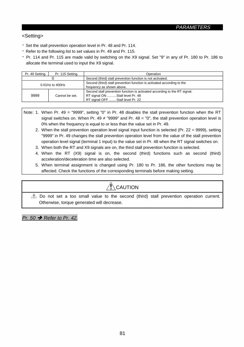
PARAMETERS
81
<Setting>
· Set the stall prevention operation level in Pr. 48 and Pr. 114.· Refer to the following list to set values in Pr. 49 and Pr. 115.· Pr. 114 and Pr. 115 are made valid by switching on the X9 signal. Set "9" in any of Pr. 180 to Pr. 186 to
allocate the terminal used to input the X9 signal.
Pr. 49 Setting Pr. 115 Setting Operation0 Second (third) stall prevention function is not activated.
0.01Hz to 400HzSecond (third) stall prevention function is activated according to thefrequency as shown above.
9999 Cannot be set.Second stall prevention function is activated according to the RT signal.RT signal ON ..........Stall level Pr. 48RT signal OFF ........Stall level Pr. 22
Note: 1. When Pr. 49 = "9999", setting "0" in Pr. 48 disables the stall prevention function when the RTsignal switches on. When Pr. 49 ≠ "9999" and Pr. 48 = "0", the stall prevention operation level is0% when the frequency is equal to or less than the value set in Pr. 49.
2. When the stall prevention operation level signal input function is selected (Pr. 22 = 9999), setting"9999" in Pr. 49 changes the stall prevention operation level from the value of the stall preventionoperation level signal (terminal 1 input) to the value set in Pr. 48 when the RT signal switches on.
3. When both the RT and X9 signals are on, the third stall prevention function is selected.4. When the RT (X9) signal is on, the second (third) functions such as second (third)
acceleration/deceleration time are also selected.5. When terminal assignment is changed using Pr. 180 to Pr. 186, the other functions may be
affected. Check the functions of the corresponding terminals before making setting.
CAUTION
Do not set a too small value to the second (third) stall prevention operation current.Otherwise, torque generated will decrease.
Pr. 50 Î Refer to Pr. 42.

PARAMETERS
82
Pr. 37 "speed display"Pr. 55 "frequency monitoring reference"Pr. 56 "current monitoring reference"Pr. 170 "watt-hour meter clear"Pr. 171 "actual operation hour meter clear"Pr. 900 "FM terminal calibration"Pr. 901 "AM terminal calibration"
Related parametersz Monitor display/FM, AM terminal function selection (Pr. 52 to Pr. 54, Pr. 158)
Pr. 52 "DU/PU main display screen data selection"
Pr. 53 "PU level display data selection"
Pr. 54 "FM terminal function selection"
Pr. 158 "AM terminal function selection"
z You can select the signals shown on the operation panel (FR-DU04)/parameter unit (FR-PU04) maindisplay screen and on the parameter unit (FR-PU04) level meter and signals output to the FM and AMterminals.
z There are two different signal outputs: FM pulse train output terminal and AM analog output terminal.Select the signals using Pr. 54 and Pr. 158.
ParameterNumber
Factory Setting Setting Range
52 0 0 to 20, 22 to 25, 10053 1 0 to 3, 5 to 14, 17, 1854 1 1 to 3, 5 to 14, 17, 18, 21
158 1 1 to 3, 5 to 14, 17, 18, 21
<Setting>Set Pr. 52 to Pr. 54 and Pr. 158 in accordance with the following table:
Parameter SettingPr.52 Pr.53 Pr.54 Pr.158
Signal Type DisplayUnit DU
LED
PUmain
monitor
PU levelmeter
FMterminal
AMterminal
Full-Scale Value ofFM, AM, Level Meter
No display × × 0 × × Output frequency Hz 0/100 0/100 1 1 1 Pr. 55Output current A 0/100 0/100 2 2 2 Pr. 56Output voltage V 0/100 0/100 3 3 3 400V or 800VAlarm display 0/100 0/100 × × × Frequency setting Hz 5 * 5 5 5 Pr. 55
Running speed r/min 6 * 6 6 6 Pr. 55 value converted into Pr. 37value
Motor torque % 7 * 7 7 7 Rated torque of applied motor × 2Converter output voltage V 8 * 8 8 8 400V or 800VRegenerative brake duty % 9 * 9 9 9 Pr. 70Electronic overcurrentprotection load factor % 10 * 10 10 10 Protection operation level
Output current peakvalue A 11 * 11 11 11 Pr. 56
Converter output voltagepeak value V 12 * 12 12 12 400V or 800V
Input power kW 13 * 13 13 13 Rated power of inverter rating × 2Output power kW 14 * 14 14 14 Rated power of inverter rating × 2Input terminal status × * × × × Output terminal status × * × × × Load meter ** % 17 17 17 17 17 Pr. 56Motor exciting current A 18 18 18 18 18 Pr. 56Position pulse 19 19 × × × Cumulative operationtime hr 20 20 × × ×
Reference voltageoutput × × × 21 21
1440Hz is output to FM terminal.Full-scale voltage is output to AMterminal.
Orientation status 22 22 × × × Actual operation time hr 23 23 × × × Motor load factor % 24 24 × × × Rated inverter current × 2Cumulative power kW 25 25 × × ×

PARAMETERS
83
When 100 is set in Pr. 52, the monitored values during stop and during operation differ as indicated below:(The LED on the left of Hz flickers during a stop and is lit during running.)
Pr. 520 100
During operation/duringstop
During stop During operation
Output frequency Output frequency Set frequency Output frequencyOutput current Output currentOutput voltage Output voltageAlarm display Alarm display
Note: 1. During an error, the output frequency at error occurrence is displayed.2. During MRS, the values are the same as during a stop. During offline auto tuning, the tuning status
monitor has priority.
Note: 1. The monitoring of items marked × cannot be selected.2. By setting "0" in Pr. 52, the monitoring of "output frequency to alarm display" can be selected in
sequence by the SHIFT key.3. *"Frequency setting to output terminal status" on the PU main monitor are selected by "other
monitor selection" of the parameter unit (FR-PU04).4. **The load meter is displayed in %, with the current set in Pr. 56 regarded as 100%.5. The motor torque display is valid only in the advanced magnetic flux vector control mode.6. The actual operation time displayed by setting "23" in Pr. 52 is calculated using the inverter
operation time. (Inverter stop time is not included.) Set "0" in Pr. 171 to clear it.7. When Pr. 53 = "0", the level meter display of the parameter unit can be erased.8. By setting "1, 2, 5, 6, 11, 17 or 18" in Pr. 53, the full-scale value can be set in Pr. 55 or Pr. 56.9. The cumulative operation time and actual operation time are calculated from 0 to 65535 hours,
then cleared, and recalculated from 0.When the operation panel (FR-DU04) is used, the display shows "----" after 9999 or more hourshave elapsed.Whether 9999 or more hours have elapsed or not can be confirmed on the parameter unit(FR-PU04).
10. The actual operation time is not calculated unless the inverter has operated for longer than onehour continuously.
11. When the operation panel (FR-DU04) is used, the display unit is Hz, V or A only.12. The orientation status functions when the FR-A5AP option is used. If the option is not used, "22"
may be set in Pr. 52 and the value displayed remains "0" and the function is invalid.

PARAMETERS
84
Pr. 37 "speed display"Pr. 53 "PU level display data selection"Pr. 54 "FM terminal function selection"Pr. 158 "AM terminal function selection"Pr. 900 "FM terminal calibration"Pr. 901 "AM terminal calibration"
Related parametersz Monitoring reference (Pr. 55, Pr. 56)
Pr. 55 "frequency monitoring reference"
Pr. 56 "current monitoring reference"
Set the frequency or current which is referenced for display when the frequency or current is selected for theFM and AM terminals and PU level meter display.
ParameterNumber
Factory Setting Setting Range
55 60Hz ⟨50Hz⟩ 0 to 400Hz
56Rated output
current0 to 500A
Pr.56Pr.55
1440 pulses/second. (terminal FM)10VDC (terminal AM)Full scale (PU level monitor)
Out
put
or d
ispl
ay
Out
put
or d
ispl
ay
Output frequencyFrequency settingRunning speed
Output currentOutput current peak valueLoad meter
1440 pulses/second. (terminal FM)10VDC (terminal AM)Full scale (PU level monitor)
<Setting>
Referring to the above figures and following table, set Pr. 55 and Pr. 56:
Monitoring ReferenceSetting Parameter
Monitored Data SelectionPU Level Display
SelectionPr. 53 Setting
FM Terminal FunctionSelection
Pr. 54 Setting
AM Terminal FunctionSelection
Pr. 158 SettingOutput frequency (Hz)) 1 1 1Frequency setting (Hz) 5 5 5
Frequency monitoringreference Pr. 55
Running speed (Pr. 37) 6 6 6Output current (A) 2 2 2Output current peak value(A)
11 11 11
Load meter (%) 17 17 17
Current monitoringreference Pr. 56
Motor exciting current (A) 18 18 18
Setting using Pr. 55, Pr. 56
Set to make the PUlevel meter indicationto be in full-scale.
Set to make theterminal FM pulse trainoutput to be 1440pulses/second.
Set to make theterminal AM outputvoltage to be 10V.
Note: 1. The maximum pulse train output of terminal FM is 2400 pulses/second. If Pr. 55 is not adjusted,the output of terminal FM will be filled to capacity. Therefore, adjust Pr. 55.
2. The maximum output voltage of terminal AM is 10VDC.

PARAMETERS
85
z Automatic restart after instantaneous power failure (Pr. 57, Pr. 58, Pr. 162 to Pr. 165)
Pr. 57 "coasting time for automatic restart after instantaneous power failure/commercial power supply-inverter switch-over"
Pr. 58 "cushion time for automatic restart after instantaneous power failure/commercial power supply-inverter switch-over"
Pr.162 "Automatic restart after instantaneous power failure selection"
Pr.163 "First cushion time for restart"
Pr.164 "First cushion voltage for restart"
Pr.165 "Restart stall prevention operation level"
z You can restart the inverter without stopping the motor (with the motor coasting) when the commercialpower supply is switched to the inverter operation or when the power is restored after an instantaneouspower failure. (When automatic restart operation is set to be enabled, UVT and IPF among the alarmoutput signals will not be output at occurrence of an instantaneous power failure.)
ParameterNumber
Factory Setting Setting Range Remarks
57 9999 0, 0.1 to 5 s, 9999 9999: No restart58 1.0 s 0 to 60 s
162 0 0, 10: Frequency search, 1: No frequencysearch
163 0 s 0 to 20 s164 0% 0 to 100%165 150% 0 to 200%
(Pr.163) Pr.58
Pr.164STF
IM
NFB
CS
SD
CSSD
S1 ⟨L21⟩R1 ⟨L11⟩
T ⟨L3⟩S ⟨L2⟩R ⟨L1⟩
MC1
MC2
×MC3
W
V
U
Connect CS-SD for use of onlyautomatic restart after instantaneous power failure.
Voltage
Time
Voltage rise time
MC switching sequence

PARAMETERS
86
<Setting>
Refer to the above figures and following table, and set the parameters:
ParameterNumber
Setting Description
0 Frequency search madeFrequency search is made after detection of an instantaneous power failure.
1621
No frequency searchIndependently of the motor coasting speed, the output voltage is gradually increasedwith the frequency kept as preset.
0.4K to 1.5K 0.5 s coasting time2.2K to 7.5K 1.0 s coasting time011K or more 3.0 s coasting time
Generally use this setting.
0.1 to 5 sWaiting time for inverter-triggered restart after power is restored from an instantaneouspower failure. (Set this time between 0.1 s and 5 s according to the inertia moment(GD2) and torque of the load.)
57
9999 No restart58 0 to 60 s
163 0 to 20 s164 0 to 100%165 0 to 200%
Normally the motor may be run with the factory settings. These values are adjustableto the load (inertia moment, torque).
Note: 1. When restart operation is selected, UVT and IPF among the alarm output signals are not outputat occurrence of an instantaneous power failure.
2. If the inverter capacity is more than one rank higher than the motor capacity, an overcurrent(OCT) alarm may take place, disabling the motor from starting.
3. When Pr. 57 ≠ 9999, the inverter will not run if the CS signal remain off.4. When Pr. 162 = "0", connection of two or more motors to one inverter will make the inverter
function improperly. (The inverter will not start properly.)5. When Pr. 162 = "0", the DC dynamic brake is operated instantly on detection of restarting speed.
Therefore, if the inertia moment (GD2) of the load is small, the speed may reduce.6. When Pr. 162 = "1", the output frequency before an instantaneous power failure is stored and
output at the time of restart. If the power of the inverter control circuit is lost, the frequency beforean instantaneous power failure cannot be stored and the inverter will start at 0Hz.
7. The SU and FU signals are not output during restart but are output after the restart cushion timehas elapsed.
CAUTION
Provide mechanical interlocks for MC1 and MC2.The inverter will be damaged if power is entered into the inverter output section.
When automatic restart after instantaneous power failure has been selected, the motor andmachine will start suddenly (after the reset time has elapsed) after occurrence of aninstantaneous power failure. Stay away from the motor and machine.When you have selected automatic restart after instantaneous power failure, apply thesupplied CAUTION seals in easily visible places.

PARAMETERS
87
•••••••
Pr. 1 "maximum frequency"Pr. 7 "acceleration time"Pr. 8 "deceleration time"Pr. 18 "high-speed maximum frequency"Pr. 28 "multi-speed input compensation"Pr. 44 "second acceleration/deceleration time"Pr. 45 "second deceleration time"
Related parametersz Remote setting function selection (Pr. 59)
Pr. 59 "remote setting function selection"
If the operator panel is located away from the control box, you can use contact signals to perform continuousvariable-speed operation, without using analog signals.z By merely setting this parameter, you can use the acceleration, deceleration and setting clear functions of
the motorized speed setter (FR-FK).z When the remote function is used, the output frequency of the inverter can be compensated for as follows:
External operation mode Frequency set by RH/RM operation plus external running frequency otherthan multi-speeds(Set "1" in Pr. 28 to select the compensation input (terminal 1).)
PU operation mode Frequency set by RH/RM operation plus PU running frequency
ParameterNumber
Factory Setting Setting Range
59 0 0, 1, 2
Out
put f
requ
ency
Acceleration (RH)
Deceleration (RM)
Clear (RL)
Forward rotation (STF)
Time
ON ON
<Setting>Refer to the following table and set the parameter:
OperationPr. 59 Setting
Remote setting functionFrequency setting storage
function0 No 1 Yes Yes2 Yes No
· Use Pr. 59 to select whether the remote setting function is used or not and whether the frequency settingstorage function in the remote setting mode is used or not. When "remote setting function - yes" isselected, the functions of terminals RH, RM and RL are changed to acceleration (RH), deceleration (RM)and clear (RL).
Note: 1. The frequency can be varied by RH (acceleration) and RM (deceleration) between 0 and themaximum frequency (Pr. 1 or Pr. 18 setting).
2. When the acceleration or deceleration signal switches on, the set frequency varies according tothe slope set in Pr. 44 or Pr. 45. The output frequency acceleration/deceleration times are as setin Pr. 7 and Pr. 8, respectively. Therefore, the longer preset times are used to vary the actualoutput frequency.
3. The frequency setting storage function stores in memory the remotely-set frequency (frequencyset by RH/RM operation) when the acceleration and deceleration signals remain off for more than1 minute or as soon as the start signal (STF or STR) switches off. When power is switched off,then on, operation is resumed with that value.

PARAMETERS
88
Pr. 0 "torque boost"Pr. 7 "acceleration time"Pr. 8 "deceleration time"Pr. 13 "starting frequency"Pr. 19 "base frequency voltage"Pr. 80, Pr. 81 (advanced magnetic flux vector control)Pr. 278 to Pr. 285 (brake sequence functions)
Related parameters
CAUTION
When selecting this function, re-set the maximum frequency according to the machine.
z Intelligent mode selection (Pr. 60)
Pr. 60 "intelligent mode selection"
The inverter automatically sets appropriate parameters for operation.
z If you do not set the acceleration and deceleration times and V/F pattern, you can run the inverter as ifappropriate values had been set in the corresponding parameters. This operation mode is useful to startoperation immediately without making fine parameter settings.
ParameterNumber
Factory Setting Setting Range
60 0 0 to 8
<Setting>
Pr. 60Setting
Operation Mode DescriptionAutomatically Set
Parameters
0 Ordinary operationmode
1, 2Shortestacceleration/deceleration mode
Set to accelerate/decelerate the motor in the shortest time. Theinverter makes acceleration/deceleration in the shortest time using its fullcapabilities. During deceleration, an insufficient brake capability may causethe regenerative overvoltage alarm (E.OV3)."1": Stall prevention operation level 150%"2": Stall prevention operation level 180%
Pr. 7, Pr. 8
3
Optimumacceleration/deceleration mode(Note 2, 4)
Optimum operation can be carried out by fully utilizing the invertercapabilities in the continuous rating range.Self-learning automatically sets the corresponding parameters so that theaverage current during acceleration/deceleration is equal to the rated current.Appropriate for applications where the load will not vary by a large ammount.
Pr. 0, Pr. 7, Pr. 8
4 Energy-savingmode (Note 3, 5)
Tunes the inverter output voltage online to minimize the inverteroutput voltage during constant-speed operation.Appropriate for energy-saving applications such as fan and pump.
Output voltage
5, 6 Elevator mode(Note 3)
Automatically controls the inverter output voltage to deliver themaximum torque in both the driving and regenerative modes. Appropriatefor a counterbalanced elevator."5": Stall prevention operation level 150%"6": Stall prevention operation level 180%
Pr. 0, Pr. 13, Pr. 19
7
Mechanicalbrake openingcompletion signalinput
8
Brake sequencemode Mechanical
brake openingcompletionsignal not input
This function causes the inverter to output themechanical brake operation timing signal for elevatingapplication.For function details and related parameter setting, referto Pr. 278 to Pr. 285 (brake sequence functions).

PARAMETERS
89
Note: 1. When more accurate control is required for your application, set the other parameters asappropriate.
2. Because of the learning system, this control is not valid at the first time in the optimumacceleration/deceleration mode. Also, this mode is only valid for frequency setting of 30.01Hz ormore.
3. When the advanced magnetic flux vector control has been selected using Pr. 80 and Pr. 81, thesettings of the energy-saving mode and elevator mode are ignored. (Advanced magnetic fluxvector control has higher priority.)
4. If an overvoltage (OV3) trip has occurred during operation in the optimumacceleration/deceleration mode (setting "3"), re-set Pr. 8 "deceleration time" to a larger value andrestart operation in this mode.
5. When the "energy-saving mode" (setting "4") is used to decelerate the motor to a stop, thedeceleration time may be longer than the preset value. Also, overvoltage is likely to occur in thismode as compared to the constant-torque load characteristics, set the deceleration time to alonger value.
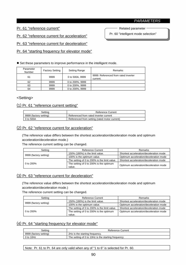
PARAMETERS
90
Pr. 60 "intelligent mode selection"
Related parameterz Acceleration/deceleration reference current/lift mode starting frequency (Pr. 61 to Pr. 64)
Pr. 61 "reference current"
Pr. 62 "reference current for acceleration"
Pr. 63 "reference current for deceleration"
Pr. 64 "starting frequency for elevator mode"
z Set these parameters to improve performance in the intelligent mode.
ParameterNumber
Factory Setting Setting Range Remarks
61 9999 0 to 500A, 99999999: Referenced from rated invertercurrent.
62 9999 0 to 200%, 999963 9999 0 to 200%, 999964 9999 0 to 200%, 9999
<Setting>
(1) Pr. 61 "reference current setting"
Setting Reference Current9999 (factory setting) Referenced from rated inverter current0 to 500A Referenced from setting (rated motor current)
(2) Pr. 62 "reference current for acceleration"
(The reference value differs between the shortest acceleration/deceleration mode and optimumacceleration/deceleration mode.)The reference current setting can be changed.
Setting Reference Current Remarks150% (180%) is the limit value. Shortest acceleration/deceleration mode
9999 (factory setting)100% is the optimum value. Optimum acceleration/deceleration modeThe setting of 0 to 200% is the limit value. Shortest acceleration/deceleration mode
0 to 200% The setting of 0 to 200% is the optimumvalue.
Optimum acceleration/deceleration mode
(3) Pr. 63 "reference current for deceleration"
(The reference value differs between the shortest acceleration/deceleration mode and optimumacceleration/deceleration mode.)The reference current setting can be changed.
Setting Reference Current Remarks150% (180%) is the limit value. Shortest acceleration/deceleration mode
9999 (factory setting)100% is the optimum value. Optimum acceleration/deceleration modeThe setting of 0 to 200% is the limit value. Shortest acceleration/deceleration mode
0 to 200% The setting of 0 to 200% is the optimumvalue.
Optimum acceleration/deceleration mode
(4) Pr. 64 "starting frequency for elevator mode"
Setting Reference Current9999 (factory setting) 2Hz is the starting frequency.0 to 10Hz The setting of 0 to 10Hz is the starting frequency.
Note: Pr. 61 to Pr. 64 are only valid when any of "1 to 6" is selected for Pr. 60.

PARAMETERS
91
z Retry function (Pr. 65, Pr. 67 to Pr. 69)
Pr. 65 "retry selection"
Pr. 67 "number of retries at alarm occurrence"
Pr. 68 "retry waiting time"
Pr. 69 "retry count display erasure"
When an alarm occurs, the retry function causes the inverter to automatically reset itself to make a restartand continue operation. You can select whether retry is made or not, alarms reset for retry, number of retriesmade, and waiting time.
ParameterNumber
Factory Setting Setting Range
65 0 0 to 567 0 0 to 10, 101 to 11068 1 s 0 to 10 s69 0 0
<Setting>
Use Pr. 65 to select alarms to be reset for retry.
Errors Reset for Retry SettingDisplay 0 1 2 3 4 5E.OC1 z z z z z
E.OC2 z z z z
E.OC3 z z z z z
E.OV1 z z z z
E.OV2 z z z z
E.OV3 z z z z
E.THM z
E.THT z
E.IPF z z
E.UVT z z
E.FINE. BE z z
E. GF z z
E. LFE.OHT z
E.OLT z z
E.OPT z z
E.OP1 z z
E.OP2 z z
E.OP3 z z
E. PE z z
E.PUEE.RETE.CPUE.E6E.E7
E.MB1 z z
E.MB2 z z
E.MB3 z z
E.MB4 z z
E.MB5 z z
E.MB6 z z
E.MB7 z z
E.P24E.CTE
Note: z indicates the errors selected for retry.

PARAMETERS
92
· Use Pr. 67 to set the number of retries at alarm occurrence.
Pr. 67 Setting Number of Retries Alarm Signal Output0 Retry is not made.
1 to 10 1 to 10 times Not output.101 to 110 1 to 10 times Output.
· Use Pr. 68 to set the waiting time from when an inverter alarm occurs until a restart in the range 0 to 10seconds.
· Reading the Pr. 69 value provides the cumulative number of successful restart times made by retry. Thesetting of "0" erases the cumulative number of times.
Note: 1. The cumulative number in Pr. 69 is incremented by "1" when retry operation is regarded assuccessful, i.e. when normal operation is continued without any alarm occurring during a periodmore than four times longer than the time set in Pr. 68.
2. If alarms occur consecutively within a period four times longer than the above waiting time, theoperation panel (FR-DU04) may show data different from the most recent data or the parameterunit (FR-PU04) may show data different from the first retry data. The data stored as the errorreset for retry is only that of the alarm which occurred the first time.
3. When an inverter alarm is reset at the restart time, the stored data of the electronic overcurrentprotection, regenerative brake duty, etc. are not cleared. (Different from the power-on reset.)
CAUTION
When you have selected the retry function, stay away from the motor and machine unlessrequired. They will start suddenly (after the reset time has elapsed) after occurrence of analarm.When you have selected the retry function, apply the supplied CAUTION seals in easilyvisible places.
Pr. 66 Î Refer to Pr. 22.
Pr. 70 Î Refer to Pr. 30.

PARAMETERS
93
Pr. 0 "torque boost"Pr. 12 "DC dynamic brake voltage"Pr. 19 "base frequency voltage"Pr. 60 "intelligent mode"Pr. 80 "motor capacity"Pr. 81 "number of motor poles"Pr. 96 "auto tuning setting/status"Pr. 100 to Pr. 109 " V/F frequency/voltage"
Related parametersz Applied motor (Pr. 71)
Pr. 71 "applied motor"
Set the motor used.
ParameterNumber
FactorySetting
Setting Range
71 0 0 to 8, 13 to 18, 20, 23, 24
<Setting>
· Refer to the following list and set this parameter according to the motor used.
MotorPr. 71Setting
Thermal Characteristics of Electronic Overcurrent ProtectionStandard
ConstantTorque
0 Thermal characteristics matching a standard motor
1 Thermal characteristics matching the Mitsubishi constant-torque motor
2Thermal characteristics matching a standard motor5-point flexible V/F characteristics
20Thermal characteristics for advanced magnetic flux vector control of the Mitsubishistandard motor SF-JR4P (1.5KW (2HP) or less)
3 Standard motor
13 Constant-torque motor
23Mitsubishi general-purpose motor SF-JR4P(1.5KW (2HP) or less)
Select "offline auto tuning setting".
4 Standard motor
14 Auto tuning data can be read or set anew.
24Mitsubishi general-purpose motor SF-JR4P(1.5KW (2HP) or less)
Constant-torque motor
5 Standard motor
15 Constant-torque motorStar connection
6 Standard motor
16 Constant-torque motorDelta connection
Motor constants canbe entered directly.
7 Standard motor
17 Constant-torque motorStar connection
8 Standard motor
18 Constant-torque motorDelta connection
Direct motorconstant entry andoffline auto tuning
· For the 5.5K and 7.5K, the Pr. 0 and Pr. 12 settings are automatically changed depending on the Pr. 71setting.Pr. 71 0, 2, 3 to 8, 20, 23, 24 1, 13 to 18Pr. 0 3% 2%
Pr. 12 4% 2%
Note: 1. When "9999" is set in Pr. 19, "2" cannot be set in Pr. 71. To set "2" in Pr. 71, set the appropriatevalue (other than "9999") in Pr. 19.
2. When "2" is set in Pr. 71, Pr. 100 to Pr. 109 are displayed on the parameter unit (FR-PU04). Inother settings, if any of Pr. 100 to Pr. 109 settings is changed, the new setting is not displayed inthe "Default parameter list" and "Set parameter list".
3. Refer to Pr. 96 for offline auto tuning.4. Set any of "3, 7, 8, 13, 17 and 18" to perform offline auto tuning.
CAUTION
Set this parameter correctly according to the motor used.Incorrect setting may cause the motor to overheat and burn.

PARAMETERS
94
z PWM carrier frequency (Pr. 72, Pr. 240)
Pr. 72 "PWM frequency selection"
Pr. 240 "Soft-PWM setting"
You can change the motor tone.
z By parameter setting, you can select Soft-PWM control which changes the motor tone.z Soft-PWM control changes motor noise from a metallic tone into an unoffending complex tone.
ParameterNumber
Factory Setting Setting Range Remarks
72 2 0 to 15 0: 0.7kHz, 15: 14.5kHz240 1 0, 1 1: Soft-PWM valid
<Setting>
· Refer to the following list and set the parameters:
ParameterNumber
Factory Setting Description
72 0 to 15 PWM carrier frequency can be changed.The setting displayed is in [kHz]. Note that 0 indicates 0.7kHz and 15 indicates 14.5kHz.
0 Soft-PWM invalid240
1 When any of "0 to 5" is set in Pr. 72, Soft-PWM is made valid.
Note: 1. A reduced PWM carrier frequency will decrease inverter-generated noise and leakage current butincrease motor noise.

PARAMETERS
95
Pr. 22 "stall prevention operation level"Pr. 903 "frequency setting voltage bias"Pr. 905 "frequency setting current gain"
Related parametersz Voltage input (Pr. 73)
Pr. 73 "0-5V/0-10V selection"
You can select the analog input terminal specifications, the override function and the function to switchbetween forward and reverse rotation depending on the input signal polarity.
ParameterNumber
Factory Setting Setting Range
73 1 0 to 5, 10 to 15
<Setting>
Pr. 73Setting
Terminal AUSignal
Terminal 2Input Voltage
Terminal 1Input Voltage
Terminal 4 Input, 4to 20mA
Override FunctionPolarity
Reversible0 ∗0 to 10V 0 to ±10V1 ∗0 to 5V 0 to ±10V2 ∗0 to 10V 0 to ±5V3 ∗0 to 5V 0 to ±5V
×
4 0 to 10V ∗0 to ±10V5 0 to 5V ∗0 to ±5V
No(Note 3)
10 ∗0 to 10V 0 to ±10V11 ∗0 to 5V 0 to ±10V12 ∗0 to 10V 0 to ±5V13 ∗0 to 5V 0 to ±5V
×
14 0 to 10V ∗0 to ±10V15
OFF(No)
0 to 5V ∗0 to ±5V
Invalid
Valid
0 0 to ±10V1 0 to ±10V2 0 to ±5V3
Invalid
0 to ±5V
×
4 0 to 10V5 0 to 5V
Invalid
No(Note 3)
10 0 to ±10V11 0 to ±10V12 0 to ±5V13
Invalid
0 to ±5V
×
14 0 to 10V15
ON(Yes)
0 to 5VInvalid
Yes
∗
Valid
Note: 1. The value of terminal 1 (frequency setting auxiliary input) is added to the main speed settingsignal of terminal 2 or 4.
2. When override has been selected, terminal 1 or 4 is for the main speed setting and terminal 2 isfor the override signal (50 to 150% at 0-5V or 0-10V).
3. Indicates that a negative-polarity frequency command signal is not accepted.4. To change the maximum output frequency at the input of the maximum frequency command
voltage (current), use the frequency setting voltage (current) gain, Pr. 903 (Pr. 905). At this time,the command voltage (current) need not be input. Also, the acceleration/deceleration time, whichis a slope up/down to the acceleration/deceleration reference frequency, is not affected by thechange in Pr. 73 setting.
5. When the Pr. 22 setting is "9999", the value of terminal 1 is for the stall prevention operation levelsetting.
6. ∗ indicates the main speed setting.

PARAMETERS
96
z Input filter time constant (Pr. 74)
Pr. 74 "filter time constant"
You can set the input section's internal filter constant of an external voltage or current frequency settingsignal.
z Effective for eliminating noise in the frequency setting circuit.z Increase the filter time constant if steady operation cannot be performed due to noise. A larger setting
results in lower response. (The time constant can be set between approximately 1ms to 1s. with the settingof 0 to 8. A larger setting results in a larger filter time constant.)
ParameterNumber
Factory Setting Setting Range
74 1 0 to 8
z Reset selection/PU disconnection detection/PU stop selection (Pr. 75)
Pr. 75 "reset selection/PU disconnection detection/PU stop selection"
You can select the reset input acceptance, PU (FR-DU04/FR-PU04) connector disconnection detectionfunction and PU stop function.• Reset selection : You can select the reset function input timing.• PU disconnection detection : When it is detected that the PU (FR-DU04/FR-PU04) connector is
disconnected from the inverter for more than 1 second, the inverter outputsan alarm code (E.PUE) and comes to an alarm stop.
• PU stop selection : When an alarm occurs in any operation mode, you can stop the motor fromthe PU by pressing the [STOP] key.
ParameterNumber
Factory Setting Setting Range
75 14 0 to 3, 14 to 17
STF ON
(STR) OFF
Stop example for external operation
Spe
ed
Operation panel
[SET] key
[STOP] key
Time
<Setting>
Pr. 75Setting
Reset Selection PU Disconnection Detection PU Stop Selection
0 Reset input normally enabled.
1 Reset input enabled only when theprotective function is activated.
If the PU is disconnected, operationwill be continued.
2 Reset input normally enabled.
3 Reset input enabled only when theprotective function is activated.
When the PU is disconnected, theinverter output is shut off.
Pressing the [STOP] key deceleratesthe motor to a stop only in the PUoperation mode.
14 Reset input normally enabled.
15 Reset input enabled only when theprotective function is activated.
If the PU is disconnected, operationwill be continued.
16 Reset input normally enabled.
17 Reset input enabled only when theprotective function is activated.
When the PU is disconnected, theinverter output is shut off.
Pressing the [STOP] key deceleratesthe motor to a stop in any of the PU,external and communication operationmodes.

PARAMETERS
97
How to make a restart after a stop made by the [STOP] key from the PU during externaloperation
(1) Operation panel (FR-DU04)1) After completion of deceleration to a stop, switch off the STF or STR signal.
2) Press the [MODE] key three times* to call the indication. (Note 8)
(*: For monitor screen)3) Press the [SET] key.4) Turn on the STF or STR signal.
(2) Parameter unit (FR-PU04)1) After completion of deceleration to a stop, switch off the STF or STR signal.2) Press the [EXT] key.3) Switch on the STF or STR signal.
Note: 1. By entering the reset signal (RES) during operation, the inverter shuts off output while it is reset,the data of the electronic overcurrent protection and regenerative brake duty are reset, and themotor coasts.
2. The PU disconnection detection function judges that the PU connector is disconnected when it isremoved from the inverter for more than 1 second. If the PU had been disconnected beforepower-on, it is not judged as an alarm.
3. To resume operation, reset the inverter after confirming that the PU is connected securely.4. When PU disconnection detection is set and the PU is then disconnected during PU jog
operation, the motor decelerates to a stop. The motor will not stop if a PU disconnection alarmoccurs.
5. The Pr. 75 value can be set any time. Also, if parameter (all) clear is executed, this setting will notreturn to the initial value.
6. When the motor is stopped by the PU stop function, PS is displayed but an alarm is not output.When the PU connector is used for RS-485 communication operation, the reset selection and PUstop selection functions are valid but the PU disconnection detection function is invalid.
7. The reset key of the PU is only valid when the protective function is activated, independent of thePr. 75 setting.
8. When Pr. 79 = "3", press the [MODE] key three times, then press the [UP/DOWN] key to display
.
CAUTION
Do not reset the inverter with the start signal on.Otherwise, the motor will start instantly after resetting, which may lead to hazardous conditions.

PARAMETERS
98
z Alarm code output selection (Pr. 76)
Pr. 76 "alarm code output selection"
When an alarm occurs, its code can be output as a 4-bit digital signal from the open collector outputterminals. When programmed operation has been selected, this parameter also serves to output a groupoperation signal.The alarm code can read by a programmable controller etc to show its remedy on a display. Also you canlook at the progress of programmed operation.
ParameterNumber
Factory Setting Setting Range
76 0 0 to 3
<Setting>
· Alarm code output
Output TerminalsPr. 76 Setting
SU IPF OL FU0 Alarm code is not output. (Depends on Pr. 190 to Pr. 195).1 Alarm code bit 3 Alarm code bit 2 Alarm code bit 1 Alarm code bit 0
2When an alarm occurs, an alarm code signal is output. (Output signal is the same as in 1.)When operation is normal, an operation status signal is output. (Output signal is the same as in 0.)
3(during programmed
operation)Output at time-out During group 3 operation During group 2 operation During group 1 operation
Note: 1. For alarm code definitions, refer to page 178.2. The Pr. 76 setting overrides the Pr. 190 to Pr. 195 settings. Therefore, if you assign other signals
to output terminals SU, IPF, OL and FU using Pr. 190 to Pr. 195, these terminals provide theoutput signals as listed above when any of "1 to 3" is set in Pr. 76. This should be noted whenusing the functions which use the output signals to exercise control.
Example: When using the brake sequence functions (Pr. 278 to Pr. 285), assign the brakeopening request signal (BOF) to the RUN terminal by setting "20" in Pr. 190.
Pr. 79 "operation mode selection"Pr. 190 to Pr. 195 (multi-function outputs)Pr. 200 to Pr. 231 "programmed operation"
Related parameters

PARAMETERS
99
z Parameter write inhibit selection (Pr. 77)
Pr. 77 "parameter write disable selection"
You can select between write-enable and disable for parameters. This function is used to prevent parametervalues from being rewritten by accident.
ParameterNumber
Factory Setting Setting Range
77 0 0, 1, 2
<Setting>
Pr. 77 Setting Function
0 Write enabled during a stop only.Parameter values may only be written during a stop in the PU operation mode.
1 Write disabled.Values of Pr.75, Pr. 77 and Pr. 79 "operation mode selection" may be written.
2 Write enabled even during operation.
Note: 1. The values of the parameters half-tone screened in the parameter list can be set at any time.
(Pr. 72 and Pr. 240 values cannot be set during external operation.)2. If Pr. 77 = "2", the values of the following parameters cannot be written during operation. Stop
operation when changing their parameter settings.
ParameterNumber
NameParameter
NumberName
23Stall prevention operation level atdouble speed
100 V/F1 (first frequency)
48Second stall prevention operationcurrent
101 V/F1 (first frequency voltage)
49Second stall prevention operationfrequency
102 V/F2 (second frequency)
60 Intelligent mode selection 103 V/F2 (second frequency voltage)61 Reference current 104 V/F3 (third frequency)
66Stall prevention operation reductionstarting frequency
105 V/F3 (third frequency voltage)
71 Applied motor 106 V/F4 (fourth frequency)79 Operation mode selection 107 V/F4 (fourth frequency voltage)80 Motor capacity 108 V/F5 (fifth frequency)81 Number of motor poles 109 V/F5 (fifth frequency voltage)
83 Rated motor voltage 135Commercial power supply-inverterswitch-over sequence outputterminal selection
84 Rated motor frequency 136 MC switch-over interlock time95 Advanced mode selection 137 Start waiting time
96 Auto tuning setting/status 138Commercial power supply-inverterswitch-over selection at alarmoccurrence
139Automatic inverter-commercialpower supply switch-over frequency
3. By setting "1" in Pr. 77, the following clear operations can be inhibited:· Parameter clear· All clear· User clear
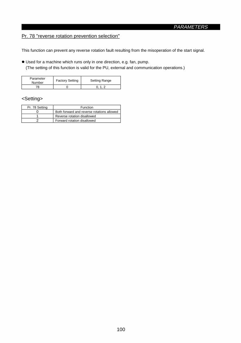
PARAMETERS
100
z Reverse rotation prevention selection (Pr. 78)
Pr. 78 "reverse rotation prevention selection"
This function can prevent any reverse rotation fault resulting from the misoperation of the start signal.
z Used for a machine which runs only in one direction, e.g. fan, pump.(The setting of this function is valid for the PU, external and communication operations.)
ParameterNumber
Factory Setting Setting Range
78 0 0, 1, 2
<Setting>
Pr. 78 Setting Function0 Both forward and reverse rotations allowed1 Reverse rotation disallowed2 Forward rotation disallowed

PARAMETERS
101
Pr. 15 "jog frequency"Pr. 4 to Pr. 6, Pr. 24 to 27, Pr.232 toPr.239 "multi-speed operation"Pr. 76 "alarm code output selection"Pr. 180 to Pr. 186 (input terminal function selection)Pr. 200 to Pr. 231 "programmed operation"
Pr. 15 "jog frequency"Pr. 4 to Pr. 6, Pr. 24 to 27, Pr.232 toPr.239 "multi-speed operation"Pr. 76 "alarm code output selection"Pr. 180 to Pr. 186 (input terminal function selection)Pr. 200 to Pr. 231 "programmed operation"
Related parametersz Operation mode selection (Pr. 79)
Pr. 79 "operation mode selection"
Used to select the operation mode of the inverter.You can choose any of the operation modes: operation using external signals (external operation), operationfrom the PU (FR-DU04/FR-PU04) (PU operation), combination of PU operation and external operation(external/PU combined operation), and computer link operation (when the FR-A5NR option is used).
ParameterNumber
Factory Setting Setting Range
79 0 0 to 8
<Setting>
Pr. 79 Setting Function0 PU or external operation can be selected.1 PU operation mode2 External operation mode
3
External/PU combined operation mode 1Running frequency ..........Set from the PU (FR-DU04/FR-PU04) (direct setting, [UP/DOWN] key) or external
signal input (multi-speed setting only)Start signal ......................External signal input (terminal STF, STR)
4External/PU combined operation mode 2
Running frequency ..........External signal input (terminal 2, 4, 1, jog, multi-speed selection)Start signal ......................Input from the PU (FR-DU04/FR-PU04) ([FWD] key, [REV] key)
5
Programmed operation modeYou can set 10 different operation starting times, rotation directions and running frequencies for each of threegroups.Operation start. ............STF, timer reset. .......... STRGroup selection ............RH, RM, RL
6Switch-over mode
Switch-over between PU operation, external operation and computer link operation (when the communicationoption such as the FR-A5NR is used) modes can be done while running.
7External operation mode (PU operation interlock)
X12 signal ON.................May be switched to PU operation mode (output stop during external operation)X12 signal OFF ...............Switching to PU operation mode inhibited
8Switching to other than external operation mode (disallowed during operation)
X16 signal ON ................Switched to external operation modeX16 signal OFF ...............Switched to PU operation mode
Note: 1. Either "3" or "4" may be set to select the PU/external combined operation. These settings differ instarting method.
(1) Programmed operation
With this function, you can set 10 different operation starting times, rotation directions and runningfrequencies individually for each of selected three groups to perform automatic operation under thecontrol of the internal elapsed time counting timer. For full information of this function, refer to theexplanations of Pr. 200 to Pr. 231.

PARAMETERS
102
(2) Switch-over mode
You can select between PU operation, external operation and computer link operation (when FR-A5NR optionis used).
Operation Mode Switching Switching Operation/Operating Status
External operation to PUoperation
1) Select the PU operation mode.z Rotation direction is the same as that of external operation.z Set frequency is as set by the potentiometer (frequency setting potentiometer). (Note that
the setting will disappear when power is switched off or the inverter is reset.)
External operation to computerlink operation
1) Mode change command to computer link mode is transmitted from the computer.z Rotation direction is the same as that of external operation.z Set frequency is as set by the potentiometer (frequency setting potentiometer). (Note that
the setting will disappear when power is switched off or the inverter is reset.)
PU operation to externaloperation
1) Press the external operation key of the parameter unit.z Rotation direction is determined by the external operation input signal.z Set frequency is determined by the external frequency setting signal.
PU operation to computer linkoperation
1) Mode change command to computer link mode is transmitted from the computer.z Rotation direction and set frequency are the same as those of PU operation.
Computer link operation toexternal operation
1) The switch-over command to the external mode is sent from the computer.z Rotation direction is determined by the external operation input signal.z Set frequency is determined by the external frequency setting signal.
Computer link operation to PUoperation
1) Select the PU operation mode with the operation panel or parameter unit.z Rotation direction and set frequency are the same as those of computer link operation.
(3) PU operation interlock
When the PU operation interlock signal is switched off, the operation mode is forcibly changed to the externaloperation mode. This function prevents the inverter from being inoperative by the external command if themode is accidentally left unswitched from the PU operation mode.
1) Preparation· Set "7" in Pr. 79 (PU operation interlock).· Using any of Pr. 180 to Pr. 186 (multi-function input terminal assignment), allocate the terminal used to
input X12 (PU external interlock signal).· When the X12 signal is not assigned, the function of the MRS signal changes from MRS (output stop) to
PU external interlock.
2) Function
X12 (MRS)Signal
Function/Operation
ON
Output stopped during external operation.Operation mode can be switched to PU operation mode.Parameter values can be rewritten in PU operationmode.PU operation allowed.
OFFForcibly switched to external operation mode.External operation allowed.Switching to PU operation mode inhibited.

PARAMETERS
103
<Function/operation changed by switching on-off the X12 (MRS) signal>
Operating Condition
Operationmode
StatusX12 (MRS)
Signal
OperationMode
(Note 4)Operating Status Parameter Write
Switchingto PU
OperationMode
During stopON → OFF
(Note 3)During stop Allowed → disallowed Disallowed
PUDuring
operationON → OFF
(Note 3)
ExternalIf external operationfrequency setting and startsignal are entered,operation is performed inthat status.
Allowed → disallowed Disallowed
OFF → ON Disallowed → disallowed AllowedDuring stop
ON → OFFDuring stop
Disallowed → disallowed DisallowedOFF → ON Disallowed → disallowed Disallowed → disallowed DisallowedExternal
Duringoperation ON → OFF
ExternalDuring operation →
output stopDisallowed → disallowed Disallowed
Note: 1. When the Pr. 79 setting is 7 and the PU operation interlock signal is OFF, network operation suchas computer link cannot be used.
2. If the X12 (MRS) signal is on, the operation mode cannot be switched to the PU operation modewhen the start signal (STF, STR) is on.
3. The operation mode switches to the external operation mode independently of whether the startsignal (STF, STR) is on or off. Therefore, the motor is run in the external operation mode whenthe X12 (MRS) signal is switched off with either of STF and STR on.
4. When an alarm occurs, the inverter can be reset by pressing the [RESET] key of the operationpanel.
5. When the MRS signal is used as the PU interlock signal, switching the MRS signal on andrewriting the Pr. 79 value to other than 7 in the PU operation mode causes the MRS signal toprovide the ordinary MRS function (output stop). Also, as soon as 7 is set in Pr. 79, the MRSsignal acts as a PU interlock signal.
6. When the MRS signal is used as the PU external interlock signal, the signal logic conforms to thePr. 17 setting. When Pr. 17 = 2, read ON for OFF and OFF for ON in the above explanation.
(4) Operation mode external signal switching function
1) PreparationSet "8" (switching to other than external operation mode) in Pr. 79. Using any of Pr. 180 to Pr. 186 (inputterminal function selection), allocate the terminal used to input the X16 (PU-external operation switching)signal.
2) FunctionWhen the X16 signal is switched on in the PU operation mode, the operation mode is forcibly changed tothe external operation mode. When the X16 signal is switched off in the external operation mode, theoperation mode is changed to the PU operation mode. When the X16 signal is switched off during networkoperation such as computer link, the operation mode is changed to the PU operation mode as soon as theswitch-over command to the external operation mode is sent from the computer. Note that this switch-overmay only be made while the inverter is at a stop and cannot be made during operation.
X16 Signal Operation ModeON External operation mode (cannot be changed to the PU operation mode)OFF PU operation mode (cannot be changed to the external operation mode)
Note: When terminal assignment is changed using Pr. 180 to Pr. 186, the other functions may be affected.Check the functions of the corresponding terminals before making setting.
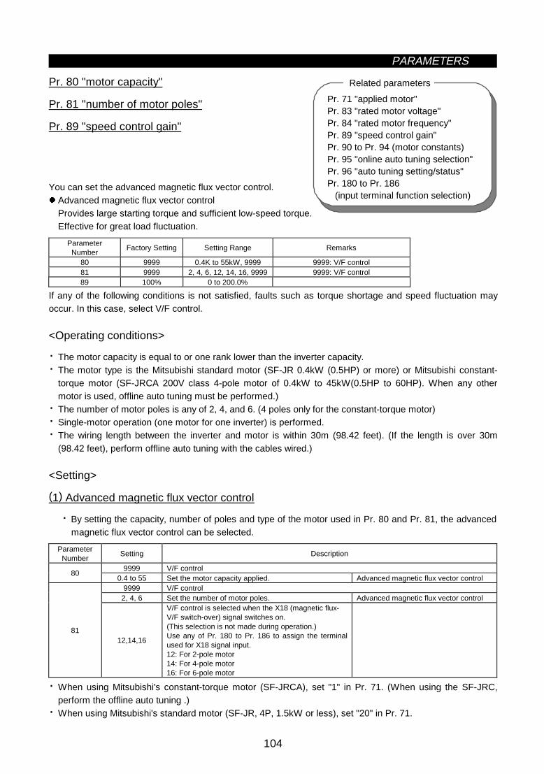
PARAMETERS
104
Pr. 71 "applied motor"Pr. 83 "rated motor voltage"Pr. 84 "rated motor frequency"Pr. 89 "speed control gain"Pr. 90 to Pr. 94 (motor constants)Pr. 95 "online auto tuning selection"Pr. 96 "auto tuning setting/status"Pr. 180 to Pr. 186 (input terminal function selection)
Related parametersz Motor capacity/number of motor poles/speed control gain (Pr. 80, Pr. 81, Pr. 89)
Pr. 80 "motor capacity"
Pr. 81 "number of motor poles"
Pr. 89 "speed control gain"
You can set the advanced magnetic flux vector control.z Advanced magnetic flux vector control
Provides large starting torque and sufficient low-speed torque.Effective for great load fluctuation.
ParameterNumber
Factory Setting Setting Range Remarks
80 9999 0.4K to 55kW, 9999 9999: V/F control81 9999 2, 4, 6, 12, 14, 16, 9999 9999: V/F control89 100% 0 to 200.0%
If any of the following conditions is not satisfied, faults such as torque shortage and speed fluctuation mayoccur. In this case, select V/F control.
<Operating conditions>
· The motor capacity is equal to or one rank lower than the inverter capacity.· The motor type is the Mitsubishi standard motor (SF-JR 0.4kW (0.5HP) or more) or Mitsubishi constant-
torque motor (SF-JRCA 200V class 4-pole motor of 0.4kW to 45kW(0.5HP to 60HP). When any othermotor is used, offline auto tuning must be performed.)
· The number of motor poles is any of 2, 4, and 6. (4 poles only for the constant-torque motor)· Single-motor operation (one motor for one inverter) is performed.· The wiring length between the inverter and motor is within 30m (98.42 feet). (If the length is over 30m
(98.42 feet), perform offline auto tuning with the cables wired.)
<Setting>
(1) Advanced magnetic flux vector control
· By setting the capacity, number of poles and type of the motor used in Pr. 80 and Pr. 81, the advancedmagnetic flux vector control can be selected.
ParameterNumber
Setting Description
9999 V/F control80
0.4 to 55 Set the motor capacity applied. Advanced magnetic flux vector control9999 V/F control
2, 4, 6 Set the number of motor poles. Advanced magnetic flux vector control
8112,14,16
V/F control is selected when the X18 (magnetic flux-V/F switch-over) signal switches on.(This selection is not made during operation.)Use any of Pr. 180 to Pr. 186 to assign the terminalused for X18 signal input.12: For 2-pole motor14: For 4-pole motor16: For 6-pole motor
· When using Mitsubishi's constant-torque motor (SF-JRCA), set "1" in Pr. 71. (When using the SF-JRC,perform the offline auto tuning .)
· When using Mitsubishi's standard motor (SF-JR, 4P, 1.5kW or less), set "20" in Pr. 71.

PARAMETERS
105
Pr. 7 "acceleration time"Pr. 9 "electronic overcurrent protection"Pr. 71 "applied motor"Pr. 80 "motor capacity"Pr. 81 "number of motor poles"Pr. 95 "online auto tuning selection"Pr. 156 "stall prevention operation selection"
Related parameters
Note: 1. Speed fluctuation is slightly greater than in the V/F control. (Advanced magnetic flux vectorcontrol may not be suitable for machines which attach importance to little speed fluctuationat low speed, e.g. grinders, lapping machines.)
2. When the surge voltage suppression filter (FR-ASF-H) is used between the inverter andmotor, output torque may reduce.
3. When the terminal functions are changed using Pr. 180 to Pr. 186, the other functions maybe affected. Confirm the functions of the corresponding terminals before making setting.
· For adjustment of motor speed fluctuation due to load variationPr. 89 can be used to adjust motor speed fluctuation when the load varies. (When you have changed theconventional model FR-A200E series for the FR-A500 series, advanced magnetic flux vector control iseffective when motor speed does not match.)
Speed
Load
torq
ue
z Offline auto tuning function (Pr. 82 to Pr. 84, Pr. 90 to Pr. 94, Pr. 96)
Pr. 82 "motor exciting current"
Pr. 83 "rated motor voltage"
Pr. 84 "rated motor frequency"
Pr. 90 "motor constant (R1)"
Pr. 91 "motor constant (R2)"
Pr. 92 "motor constant (L1)"
Pr. 93 "motor constant (L2)"
Pr. 94 "motor constant (X)"
Pr. 96 "auto tuning setting/status"
When you use the advanced magnetic flux vector control, you can perform the offline auto tuning operation tocalculate motor constants automatically.z Offline auto tuning is made valid only when other values than "9999" are set in Pr. 80 and Pr. 81 to select
the advanced magnetic flux vector control.z The offline tuning data (motor constants) can be copied to another inverter with the PU (FR-DU04/
FR-PU04).z If the motor used is not Mitsubishi's standard motor or Mitsubishi's constant-torque motor (e.g. motor of
another company make) or the wiring distance is long, the motor can be run with the optimum operatingcharacteristics by using the offline auto tuning function.
z Offline auto tuningAutomatically measures the motor constants used for advanced magnetic flux vector control.· Offline auto tuning can be performed with the load connected. (As the load is smaller, tuning accuracy is
higher. Tuning accuracy does not change if inertia is large.)· For the offline auto tuning, you can select either the motor non-rotation mode or rotation mode.
Note that when making selection for the online auto tuning, the motor-only rotation mode should beselected.
· You can read, write and copy the motor constants tuned by the offline auto tuning.· The offline auto tuning status can be monitored with the PU (FR-DU04/FR-PU04).

PARAMETERS
106
ParameterNumber
Factory Setting Setting Range Remarks
82 9999 0 to , 9999 9999: Mitsubishi standard motor83 200V 0 to 1000V Rated motor voltage84 60Hz 50 to 120Hz Rated motor frequency90 9999 0 to , 9999 9999: Mitsubishi standard motor91 9999 0 to , 9999 9999: Mitsubishi standard motor92 9999 0 to , 9999 9999: Mitsubishi standard motor93 9999 0 to , 9999 9999: Mitsubishi standard motor94 9999 0 to , 9999 9999: Mitsubishi standard motor96 0 0, 1, 101 0: No tuning
<Operating conditions>
· The motor is connected.· The motor capacity is equal to or one rank lower than the inverter capacity. (0.4kW or more)· The maximum frequency is 120Hz.· Special motors such as high-slip motor and high-speed motor cannot be tuned.· When "101" (offline auto tuning with motor running) is set in Pr. 96, note the following:
1) Torque may not be enough during tuning.2) The motor may be run at nearly its rated frequency (Pr. 84 setting) without problem.3) The brake is open.4) No external force is applied to rotate the motor.
· If "1" (tuning without motor running) is set in Pr. 96, the motor may run slightly. Therefore, fix the motorsecurely with a mechanical brake, or before tuning, make sure that there will be no problem in safety if themotor runs.This instruction must be followed especially for vertical lift applications.Note that if the motor runs slightly, tuning performance is unaffected.
Note: Offline auto tuning will not be performed properly if it is performed when the reactor or surgevoltage suppression filter (FR-ASF-H) is connected between the inverter and motor.Remove it before starting tuning.
<Setting>
(1) Parameter setting
· Using Pr. 80 and Pr. 81, select the advanced magnetic flux vector control.· Refer to the parameter details list and set the following parameters:
1) Set "1" or "101" in Pr. 96.· For setting of "1" ................................................................................ Tuning without motor running.· For setting of "101" ............................................................................ Tuning with motor running.
2) Set the rated motor current (A) in Pr. 9.3) Set the rated motor voltage (V) in Pr. 83.4) Set the rated motor frequency (Hz) in Pr. 84.5) Select the motor using Pr. 71.
· Standard motor .................................................................................. Pr. 71 = "3"· Constant-torque motor....................................................................... Pr. 71 = "13"· Mitsubishi standard motor SF-JR 4 poles (1.5kW (2HP) or less)...... Pr. 71 = "23"
Note: Pr. 83 and Pr. 84 are only displayed when the advanced magnetic flux vector control isselected (Pr. 80, Pr. 81).In these parameters, set the values given on the motor plate. When the standard motor hasmore than one rated value, set 200V/60Hz or 400V/60Hz.

PARAMETERS
107
Parameter details
ParameterNumber
Setting Description
9 0 to 500A Set the rated motor current (A).
0Electronic overcurrent protection thermal characteristics suitable for general-purposemotor
1Electronic overcurrent protection thermal characteristics suitable for Mitsubishi'sconstant-torque motor
2Electronic overcurrent protection thermal characteristics suitable for general-purposemotor5-point flexible V/F characteristics
20Mitsubishi's SF-JR4P general-purpose motor (1.5kW (2HP) or less), Electronicovercurrent protection thermal characteristics for advanced magnetic flux vectorcontrol
3 Standard motor13 Constant-torque motor
23Mitsubishi's SF-JR4P standard motor(1.5kW (2HP) or less)
Select "offline auto tuning setting"
4 Standard motor14 Constant-torque motor
24Mitsubishi's SF-JR4P standard motor(1.5kW (2HP) or less)
Auto tuning read or change settingenabled
5 Standard motor15 Constant-torque motor
Star connection
6 Standard motor16 Constant-torque motor
Delta connection
Direct input ofmotor constantsenabled
7 Standard motor17 Constant-torque motor
Star connection
8 Standard motor
71 (Note 1)
18 Constant-torque motorDelta connection
Direct input ofmotor constantsand offline autotuning
83 0 to 1000V Set the rated motor voltage (V).84 50 to 120Hz Set the rated motor frequency (Hz).90 0 to , 999991 0 to , 999992 0 to , 999993 0 to , 9999
999994
0 to 100%
Tuning data(Values measured by offline auto tuning are set automatically.)
0 Offline auto tuning is not performed.1 Offline auto tuning is performed without motor running.96 (Note 2)
101 Offline auto tuning is performed with motor running.
Note: 1. The electronic overcurrent protection characteristics are also selected simultaneously.2. Select "101" to increase tuning accuracy.
(2) Tuning execution
· For PU operation, press the [FWD] or [REV] key.· For external operation, switch on the run command.
Note: 1. When "101" is set in Pr. 96, guard against hazards because the motor rotates.2. To force tuning to end
· Switch on the MRS or RES signal or press the [STOP] key to end.· Switch off the tuning start command or make a forced stop.
3. During offline auto tuning, the following I/O signals are only valid:· Input signals
STOP, OH, MRS, RT, CS, RES, STF, STR· Output signals
RUN, OL, IPF, FM, AM, A, B, C4. Special caution should be exercised when a sequence has been designed to open the
mechanical brake with the RUN signal.

PARAMETERS
108
(3) Monitoring the offline tuning status
When the parameter unit (FR-PU04) is used, the Pr. 96 value is displayed during tuning on the mainmonitor as shown below. When the operation panel (FR-DU04) is used, only the same numerical value ason the PU is displayed:
· Parameter unit (FR-PU04) main monitor (For inverter trip)
1. Setting2. Tuning in
progress3. Completion 4. Error-activated end
STOP PU
1FWD PU
2STF
TUNE
STOP PU
3STF
TUNECOMPLETION
Display
STOP PU101
FWD PU
102STF
TUNE
STOP PU
103
STF
TUNECOMPLETION
STOP PU
9STF
TUNEERROR
· Operation panel (FR-DU04) display
(For inverter trip)
1. Setting2. Tuning in
progress3. Completion 4. Error-activated end
1 2 3Displayedvalue 101 102 103
9
· Reference: Offline auto tuning time (factory setting)
Offline Auto Tuning Setting Time1: No-rotation mode Approximately 25 seconds
2: Rotation mode
Approximately 40 seconds(Offline auto tuning time varies with acceleration and deceleration time settings asindicated below:Offline auto tuning time = acceleration time + deceleration time + approximately 30seconds)
(4) Ending the offline auto tuning
1) Confirm the Pr. 96 value.· Normal end: "3" or "103" is displayed.· Error-activated end: "9", "91", "92" or "93" is displayed.· Forced end ... "8" is displayed.
2) When tuning ended normally.For PU operation, press the [STOP] key. For external operation, switch off the start signal (STF or STR).This operation resets the offline auto tuning and the PU's monitor display returns to the ordinary indication.(Without this operation, next operation cannot be done.)
3) When tuning was ended due to an error.Offline auto tuning did not end normally. (Motor constants have not been set.) Reset the inverter and starttuning all over again.
4) Error display definitions.
Error Display Error Cause Remedy9 Inverter trip Re-set.
91Current limit (stall prevention) function wasactivated.
Increase acceleration/deceleration time.Set "1" in Pr. 156.
92Inverter output voltage reached 75% of ratedvalue.
Check for fluctuation of power supply voltage.
93 Calculation error Check the motor wiring and re-set.
No connection with motor will result in 93 error.

PARAMETERS
109
5) When tuning was forced to endA forced end occurs when tuning is forced to end by pressing the [STOP] key or turning off the start signal(STF or STR) during tuning.In this case, offline auto tuning was not brought to a normal end. (The motor constants are not yet set.)Reset the inverter and restart tuning.
Note: 1. The motor constants measured once in the offline auto tuning are stored as parameters and theirdata is held until the offline auto tuning is performed again.
2. An instantaneous power failure occurring during tuning will result in a tuning error. After power isrestored, the inverter goes into the ordinary operation mode. Therefore, when STF (STR) is on,the motor runs in forward (reverse) rotation.
3. When "8888" is set in Pr. 11, the tuning is forced to end and the DC dynamic brake is startedupon input of the MRS signal.
4. Any alarm occurring during tuning is handled as in the ordinary mode.Note that if an error retry has been set, retry is ignored.
5. The set frequency monitor displayed during the offline auto tuning is 0Hz.
CAUTION
Note that the motor may start running suddenly.
When the offline auto tuning is used in vertical lift application, e.g. a lifter, it may drop due toinsufficient torque.
<Setting the motor constants as desired>
The motor constants (Pr. 90 to Pr. 94) may be set as desired in either of two ways; the data measuredin the offline auto tuning is read and utilized or changed, or the motor constants are set without theofflineauto tuning data being used.
To utilize or change the offline auto tuning data<Operating procedure>
1. Set "801" in Pr. 77. Only when the Pr. 80 and Pr. 81 settings are other than "9999", the parametervalues of the motor constants (Pr. 90 to Pr. 94) can be displayed. Though the parameter values ofother than the motor constants (Pr. 90 to Pr. 94) can also be displayed, they are parameters formanufacturer setting and should be handled carefully without misuse.
2. Set any of the following values in Pr. 71:
· Standard motor ...................................................................................... Pr. 71 = "4"
· Constant-torque motor........................................................................... Pr. 71 = "14"
· Mitsubishi standard motor SF-JR 4 poles (1.5kW (2HP) or less).......... Pr. 71 = "24"
3. In the parameter setting mode, read the following parameters and set desired values. (Note 1)
ParameterNumber
Name Setting RangeSetting
IncrementsFactorySetting
82 Motor exciting current 0 to ****, 9999 1 999990 Motor constant R1 0 to ****, 9999 1 999991 Motor constant R2 0 to ****, 9999 1 999992 Motor constant L1 0 to ****, 9999 1 999993 Motor constant L2 0 to ****, 9999 1 999994 Motor constant X 0 to ****, 9999 1 9999
4. Return the Pr. 77 setting to the original value.

PARAMETERS
110
Note: 1. Pr. 90 to Pr. 94 values may only be read when the Pr. 80 and Pr. 81 settings are other than"9999" (advanced magnetic flux vector control selected).
2. Set "9999" in Pr. 90 to Pr. 94 to use the standard motor constants (including those for theconstant-torque motor).
3. Set "3" (standard motor), "13" (constant-torque motor) or "23" (Mitsubishi standard motor SF-JR4P (1.5kW (2HP) or less)) in Pr. 71 to use the constants measured in the offline auto tuning. Set"4, 14 or 24" in Pr. 71 and change the motor constants to change the values measured in theoffline auto tuning.
4. As the motor constants measured in the offline auto tuning have been converted into internal data(****), refer to the following setting example when making setting:Setting example: To slightly increase Pr. 90 value
When Pr. 90 is displayed "2516", set 2642, i.e. 2516×1.05=2641.8, in Pr. 90.(The value displayed has been converted into a value for internal use. Hence, simple addition of agiven value to the displayed value has no significance.)
To set the motor constants without using the offline auto tuning dataThe Pr. 92 and Pr. 93 motor constants may either be entered in [Ω] or in [mH]. Before startingoperation, confirm which motor constant unit is used.z To enter the Pr. 92 and Pr. 93 motor constants in [Ω]<Operating procedure>
1. Set "801" in Pr. 77. Only when the Pr. 80 and Pr. 81 settings are other than "9999", the parametervalues of the motor constants (Pr. 90 to Pr. 94) can be displayed. Though the parameter valuesof other than the motor constants (Pr. 90 to Pr. 94) can also be displayed, they are parametersfor manufacturer setting and should be handled carefully without misuse.
2. Set any of the following values in Pr. 71:Star Connection Motor Delta Connection Motor
Standard motor 5 6Setting
Constant-torque motor 15 16
3. In the parameter setting mode, read the following parameters and set desired values:Parameter
NumberName Setting Range
SettingIncrements
FactorySetting
90 Motor constant R1 0 to 10Ω, 9999 0.001Ω 999991 Motor constant R2 0 to 10Ω, 9999 0.001Ω 999992 Motor constant X1 0 to 10Ω, 9999 0.001Ω 999993 Motor constant X2 0 to 10Ω, 9999 0.001Ω 999994 Motor constant X 0 to 500Ω, 9999 0.01Ω 9999
4. Refer to the following table and set Pr. 84:Parameter
NumberName Setting Range
SettingIncrements
FactorySetting
84 Rated motor frequency 50 to 120Hz 0.01Hz 60Hz ⟨50Hz⟩
5. Return the Pr. 77 setting to the original value.
Note: 1. Pr. 90 to Pr. 94 values may only be read when the Pr. 80 and Pr. 81 settings are otherthan "9999" (advanced magnetic flux vector control selected).
2. Set "9999" in Pr. 90 to Pr. 94 to use the standard motor constants (including those for theconstant-torque motor).
3. If "star connection" is mistaken for "delta connection" or vice versa during setting of Pr.71, advanced magnetic flux vector control cannot be exercised normally.

PARAMETERS
111
Pr. 71 "applied motor"Pr. 80 "motor capacity"Pr. 81 "number of motor poles"Pr. 83 "rated motor voltage"Pr. 84 "rated motor frequency"Pr. 89 "speed control gain"Pr. 90 to Pr. 94 (motor constants)Pr. 96 "auto tuning setting/status"
Related parameters
z To enter the Pr. 92 and Pr. 93 motor constants in [mH]<Operating procedure>1. Set "801" in Pr. 77. Only when the Pr. 80 and Pr. 81 settings are other than "9999", the parameter
values of the motor constants (Pr. 90 to Pr. 94) can be displayed. Though the parameter (Pr. 82 toPr. 99) values of other than the motor constants (Pr. 90 to Pr. 94) can also be displayed, they areparameters for manufacturer setting and should be handled carefully without misuse.
2. Set any of the following values in Pr. 71:
· Standard motor ...................................................................................... Pr. 71 = "0"
· Constant-torque motor........................................................................... Pr. 71 = "1"
· Mitsubishi standard motor SF-JR 4 poles (1.5kW (2HP) or less).......... Pr. 71 = "20"
3. In the parameter setting mode, read the following parameters and set desired values:
ParameterNumber
Name Setting RangeSetting
IncrementsFactorySetting
90 Motor constant R1 0 to 50Ω, 9999 0.001Ω 999991 Motor constant R2 0 to 50Ω, 9999 0.001Ω 999992 Motor constant L1 0 to 1000mH, 9999 0.1mH 999993 Motor constant L2 0 to 1000mH, 9999 0.1mH 999994 Motor constant X 0 to 100%, 9999 0.1% 9999
4. Refer to the following table and set Pr. 84:
ParameterNumber
Name Setting RangeSetting
IncrementsFactorySetting
84 Rated motor frequency 50 to 120Hz 0.01Hz 60Hz ⟨50Hz⟩
5. Return the Pr. 77 setting to the original value.
Note: 1. Pr.90 to Pr. 94 values may only be read when the Pr. 80 and Pr. 81 settings are other than"9999" (advanced magnetic flux vector control selected).
2. Set "9999" in Pr. 90 to Pr. 94 to use the standard motor constants (including those for theconstant-torque motor).
Pr. 89 Î Refer to Pr. 80.
z Online auto tuning selection (Pr. 95)
Pr. 95 "online auto tuning selection"
By online auto tuning, the motor conditions are tuned rapidly at the start. This enables precise operationunaffected by motor temperatures and steady high-torque operation down to super-low speed. After settingthe Pr. 80 and Pr. 81 values, select online auto tuning with Pr. 95.z Online auto tuning
Use this function when steady high-torque operation is required for low-speed operation under advancedmagnetic flux vector control.· Before starting the online auto tuning, perform the offline auto tuning. Data must be calculated.

PARAMETERS
112
ParameterNumber
Factory Setting Setting Range Remarks
95 0 0, 1 1: Online auto tuning
<Operating conditions>
· Data required for online auto tuning is calculated in offline auto tuning. Before starting the operation ofthis function, always execute the offline auto tuning once more. The offline auto tuning is also requiredfor use of the Mitsubishi standard motor (SF-JR) or constant-torque motor (SF-JRCA).
· Offline auto tuning should be carried out with "101" (motor running) set in Pr. 96 and with the motordisconnected from the load. (The motor may be connected with inertia load.)
<Operating procedure>
1) Read the Pr. 96 value and make sure that its setting is "3 or 103" (offline auto tuning complete).2) Set "1" in Pr. 95 to select the online auto tuning.3) Before starting operation, make sure that the following parameter values have been set:
ParameterNumber
Description
9 (Used as either the rated motor current or electronic overcurrent protection parameter)71 Applied motor80 Motor capacity (down to one rank lower, between 0.4kW and 55kW)81 Number of motor poles
4) Give the run command in the PU or external operation mode.
Note: 1. If any of the inverter starting conditions are not satisfied, e.g. when MRS is input, if the setfrequency is lower than the starting frequency (Pr. 13) value, or during an inverter error, theonline auto tuning is not activated.
2. For a restart during deceleration or DC dynamic brake operation, the online auto tuning is notactivated.
3. The online auto tuning is invalid for programmed operation or jog operation.4. When automatic restart after instantaneous power failure is selected, it overrides the online
auto tuning.5. For use in vertical lift application, examine the use of a brake sequence for brake opening
timing at the start. Though the tuning ends in about a maximum of 500ms after a start,enough torque is not provided during that period. Therefore, note that the load may drop withgravity.
6. Zero current detection and output current detection are also valid during the online autotuning.
7. The RUN signal is not output during the online auto tuning. The RUN signal switches on at astart.
8. When programmed operation is selected (Pr. 79 = 5), the online auto tuning is invalid and isnot executed.
9. If the period between inverter stop and restart is within 4 seconds, the online auto tuning isexecuted but operation will not reflect the tuning results.
Pr. 96 Î Refer to Pr. 82.

PARAMETERS
113
Pr. 19 "base frequency voltage"Pr. 47 "second V/F (base frequency)"Pr. 60 "intelligent mode selection"Pr. 71 "applied motor"Pr. 113 "third V/F (base frequency)"
Related parametersz V/F control frequency (voltage) (Pr. 100 to Pr. 109)
Pr. 100 "V/F1 (first frequency)"
Pr. 101 "V/F1 (first frequency voltage)"
Pr. 102 "V/F2 (second frequency)"
Pr. 103 "V/F2 (second frequency voltage)"
Pr. 104 "V/F3 (third frequency)"
Pr. 105 "V/F3 (third frequency voltage)"
Pr. 106 "V/F4 (fourth frequency)"
Pr. 107 "V/F4 (fourth frequency voltage)"
Pr. 108 "V/F5 (fifth frequency)"
Pr. 109 "V/F5 (fifth frequency voltage)"
You can make a dedicated V/F pattern by using V/F (frequency Voltage/Frequency) control to set V/Fcharacteristics from the start to the basic frequency and basic voltage as desired.
z Desired V/F characteristics can be set by presetting V/F1 (first frequency voltage/first frequency), V/F2,V/F3, V/F4 and V/F5 in the corresponding parameters.
ParameterNumber
Factory Setting Setting Range Remarks
100 9999 0 to 400Hz, 9999101 0 0 to 1000V102 9999 0 to 400Hz, 9999103 0 0 to 1000V104 9999 0 to 400Hz, 9999105 0 0 to 1000V106 9999 0 to 400Hz, 9999107 0 0 to 1000V108 9999 0 to 400Hz, 9999109 0 0 to 1000V
Set "2" in Pr. 71 and a valueother than 9999 in Pr. 19.These functions are notactivated when any of "1 to8" is set in Pr. 60.
0
V/F5V/F4
V/F3
V/F2
V/F1
Voltage
Base frequency voltage(Pr. 19)
Boost value(Pr. 0)
V/F characteristic
Base frequency(Pr. 3)
Frequency
<Setting>
(1) Confirm the settings of Pr. 19, Pr. 60 and Pr. 71.
Parameter Number Description
19 Set the rated motor voltage.This function is not activated if its value is "9999" and "8888" (factory setting).
60 Set "0" (ordinary operation mode).71 Set "2" (V/F 5-point flexible characteristic).

PARAMETERS
114
(2) Set the desired frequencies and voltages in Pr. 100 to Pr. 109.· The setting must satisfy the following relationship: F1≠F2≠F3≠F4≠F5≠Pr. 19 "base frequency".
If the set frequencies are the same, a write error occurs.If any frequency setting is "9999", its point is ignored.
Note: 1. The V/F 5-point flexible characteristic functions for V/F control only. It does not function foradvanced magnetic flux vector control.
2. The V/F 5-point flexible characteristic does not function when Pr. 60 is selected.3. The frequency voltage setting should be equal to or less than the Pr. 3 and Pr. 19 settings.4. Pr. 19 must be set. (When Pr. 19 = "9999", Pr. 71 cannot be set to "2" (5-point flexible V/F
characteristic).)5. If "2" is set in Pr. 71, Pr. 47 and Pr. 113 do not function.6. When "2" is set in Pr. 71, the electronic overcurrent protection is calculated for a standard motor.
Pr. 110, Pr. 111 Î Refer to Pr. 7.
Pr. 112 Î Refer to Pr. 0.
Pr. 113 Î Refer to Pr. 3.
Pr. 114, Pr. 115 Î Refer to Pr. 48.
Pr. 116 Î Refer to Pr. 42.
z Computer link operation (Pr. 117 to Pr. 124)
Pr. 117 "station number"
Pr. 118 "communication speed"
Pr. 119 "stop bit length/data length"
Pr. 120 "parity check presence/absence"
Pr. 121 "number of communication retries"
Pr. 122 "communication check time interval"
Pr. 123 "waiting time setting"
Pr. 124 "CR, LF presence/absence selection"
Used to perform required settings for RS-485 communication between the inverter and personal computer.Using the inverter setup software (FR-SW0-SETUP-WE (or -WJ for Japanese version)), parameter setting,monitoring, etc. can be done efficiently.z The motor can be run from the PU connector of the inverter using RS-485 communication.
Communication specifications
Conforming standard RS-485Number of inverters connected 1:N (maximum 32 inverters)Communication speed Selected between 19200, 9600 and 4800bpsControl protocol AsynchronousCommunication method Half-duplex
Character system ASCII (7 bits/8 bits) selectableStop bit length Selectable between 1 bit and 2 bits.Terminator CR/LF (presence/absence selectable)
Parity check Selected between presence (even/odd) or absenceCheck system
Sumcheck Present
Com
mun
icat
ion
spec
ifica
tions
Waiting time setting Selectable between presence or absence

PARAMETERS
115
z For the data codes of the parameters, refer to the data code list in the appendices.
ParameterNumber
FactorySetting
Setting Range
117 0 0 to 31118 192 48, 96, 192
Data length 8 0, 1119 1
Data length 7 10, 11120 2 0, 1, 2121 1 0 to 10, 9999122 0 <9999> 0 to 999.8 sec, 999123 9999 0 to 150ms, 9999124 1 0, 1, 2
<Setting>
To make communication between the personal computer and inverter, the communication specificationsmust be set to the inverter initially. If initial setting is not made or there is a setting fault, data transfer cannotbe made.Note: After making the initial setting of the parameters, always reset the inverter. After you have changed the
communication-related parameters, communication cannot be made if the inverter is not reset.
ParameterNumber
Name Setting Description
117 Stationnumber
0 to 31Station number specified for communication from the PU connector.Set the inverter station numbers when two or more inverters are connected to onepersonal computer.
48 4800 baud96 9600 baud118
Communi-cationspeed 192 19200 baud
0 Stop bit length 1 bit8 bits
1 Stop bit length 2 bits
10 Stop bit length 1 bit119
Stop bitlength/datalength 7 bits
11 Stop bit length 2 bits0 Absent1 Odd parity present120
Parity checkpresence/absence 2 Even parity present
0 to 10Set the permissible number of retries at occurrence of data receive error. If thenumber of consecutive errors exceeds the permissible value, the inverter will cometo an alarm stop.
121Number ofcommunica-tion retries 9999
(65535)
If a communication error occurs, the inverter will not come to an alarm stop. At thistime, the inverter can be coasted to a stop by MRS or RESET input.During an error, the light fault signal (LF) is given to the open collector output.Allocate the used terminal with any of Pr. 190 to Pr. 195 (output terminal functionselection).
0 No communication0.1 to 999.8 Set the communication check time [sec] interval.122
Communi-cationcheck timeinterval 9999
If a no-communication state persists for longer than the permissible time, theinverter will come to an alarm stop.
0 to 150ms Set the waiting time between data transmission to the inverter and response.123 Waiting
time setting 9999 Set with communication data.0 Without CR/LF1 With CR124
CR, LFpresence/absenceselection 2 With CR/LF

PARAMETERS
116
<Computer programming>
(1) Communication protocol
Data communication between the computer and inverter is performed using the following procedure:
*1
*2
Computer
Inverter
↓ (Data flow)
Computer
↓ (Data flow)
Inverter
Data read
Data write
Time1)
2) 3)
4)
5)
*1. If a data error is detected and a retry must be made, execute retry operation from the user program.The inverter comes to an alarm stop if the number of consecutive retries exceeds the parametersetting.
*2. On receipt of a data error occurrence, the inverter returns “reply data 3” to the computer again. Theinverter comes to an alarm stop if the number of consecutive data errors reaches or exceeds theparameter setting.
(2) Communication operation presence/absence and data format types
Communication operation presence/absence and data format types are as follows:
No. Operation RunCommand
RunningFrequency
ParameterWrite
Inverter Reset MonitoringParameter
Read
1)Communication request is sent to theinverter in accordance with the userprogram.
A’ A A A B B
2) Inverter data processing time Present Present Present Absent Present Present
No error
Request acceptedC C C Absent E
E’ E
3)
Reply data from theinverter(Data 1 is checked forerror) With error
request rejected D D D Absent F F
4) Computer processing delay time Absent Absent Absent Absent G GNo error
No processingAbsent Absent Absent Absent G G
5)
Answer fromcomputer in responseto reply data 3(Data 3 is checked forerror)
With error data3 is output Absent Absent Absent Absent H H
(3) Data format
Hexadecimal data is used. Data is automatically transferred in ASCII between the computer and inverter.1) Data format types
(1) Communication request data from computer to inverter
*3ENQ *4
1 2 3 4 5 6 7 8 9 10 11 12 13
*3ENQ *4
1 2 3 4 5 6 7 8 9 10 11
*3ENQ
*4
1 2 3 4 5 6 7 8 9
[Data format]
Format A
[Data read]
Format A'
Format B
Inverterstationnumber
Instructioncode
*5Waiting
time
Data
Sumsheck
Inverterstationnumber
Inverterstationnumber
Instructioncode
Instructioncode
*5Waiting
time
*5Waiting
time
Data
Sumsheck
Sumsheck
←Number of characters
←Number of characters
←Number of characters

PARAMETERS
117
Note: 1. The inverter station numbers may be set between H00 and H1F (stations 0 and 31) inhexadecimal.
2. *3 indicates the control code.3. *4 indicates the CR or LF code.
When data is transmitted from the computer to the inverter, codes CR (carriage return)and LF (line feed) are automatically set at the end of a data group on some computers. Inthis case, setting must also be made from the inverter according to the computer.Also, the presence and absence of the CR and LF codes can be selected using Pr. 124.
4. *5: When Pr. 123 "waiting time setting" ≠ 9999, create the communication request datawith no "waiting time" in the data format. (The number of characters decreases by 1.)
2) Send data from computer to inverter during data write
*3ACK
*4
1 2 3 4
*3NAK
1 2 3 4
*4
5
[No data error detected] [Data error detected]
Format C Format DInverterstationnumber
Inverterstationnumber
Errorcode
←Number of characters←Number of characters
3) Reply data from inverter to computer during data read
1 2 3 4 5
1 2 3 4 5 6 7 8 9 10 11
[No data error detected]
1 2 3 4 5 6 7 8 9
*3STX
Format E
Inverterstationnumber
Readdata
Sumcheck
←Number of characters
Format E'
*3ETX *4Read data
Inverterstationnumber
Sumcheck
*4*3
ETX*3
STX
[Data error detected]
Format F
*3NAK
Errorcode
*4
Inverterstationnumber
4) Reply data from computer to inverter during data read
1 2 3 4 1 2 3 4
[No data error detected]
*3ACK
Format GInverterstationnumber
←Number of characters
Format H*4*3
NAK
[Data error detected]
*4Inverterstationnumber
←Number of characters
(4) Data definitions
1) Control codes
Signal ASCII Code DescriptionSTX H02 Start of Text (Start of data)ETX H03 End of Text (End of data)ENQ H05 Enquiry (Communication request)ACK H06 Acknowledge (No data error detected)LF H0A Line FeedCR H0D Carriage Return
NAK H15 Negative Acknowledge (Data error detected)
2) Inverter station numberSpecify the station number of the inverter which communicates with the computer.
3) Instruction codeSpecify the processing request (e.g. operation, monitoring) given by the computer to the inverter. Hence,the inverter can be run and monitored in various ways by specifying the instruction code as appropriate.
4) DataIndicates the data such as frequency and parameters transferred to and from the inverter. The definitionsand ranges of set data are determined in accordance with the instruction codes. (Refer to Appendix 1.)

PARAMETERS
118
5) Waiting timeSpecify the waiting time between the receipt of data at the inverter form the computer and the transmissionof reply data. Set the waiting time in accordance with the response time of the computer between 0 and150ms in 10ms increments (e.g. 1 = 10ms, 2 = 20ms).
Computer
↓Inverter
Inverter
↓Computer
Inverter data processing time=waiting time + data check time (set value×10ms) (12ms)
6) Sum check codeThe sum check code is 2-digit ASCII (hexadecimal) representing the lower 1 byte (8 bits) of the sum(binary) derived from the checked ASCII data.
10 1 E 1 0 7 A D F 4
H05 H30 H31 H31H45 H31 H30 H37 H41 H44 H46 H34
(Example1)
Computer→Inverter
ASCII code→
Stationnumber
Instructioncode
*Wai
ting
time
Data Sum checkcode
←Binary code
Sum
↓
30 + 31 + 45 + 31 + 31 + 30 + 37 + 41 + 44
=1F4
HH H H H H H H H
H
0 1 1 7 0 3 0
H02 H30 H31 H37H31 H37 H30 H03 H33 H30
7
(Example2)
Inverter→Computer
ASCII code→ ←Binary code
Sum checkcode
STX Stationnumber
Read data ETX
Sum
↓
30 + 31 + 31 + 37 + 37 + 30
=130
HH H H H H
H
ENQ
*When Pr. 123 "waiting time setting" ≠‚ 9999, create the communication request data with no "waiting time" in the data format. (The number of characters is decreased by 1.)
7) Error codeIf any error is found in the data received by the inverter, its definition is sent back to the computer togetherwith the NAK code.
Note: 1. When the data from the computer has an error, the inverter will not accept that data.2. Any data communication, e.g. run command, monitoring, is started when the computer
gives a communication request. Without the computer's command, the inverter does notreturn any data. For monitoring, therefore, design the program to cause the computer toprovide a data read request as required.
3. Data for link parameter expansion setting differs as indicated below between access toPr. 0 to Pr. 99 values and access to Pr. 100 to Pr. 905:
InstructionCode
Data
Read H7F H00: Pr. 0 to Pr. 99 values are accessible.
Link parameterexpansion setting Write HFF
H00: Pr. 0 to Pr. 99 values are accessible.H01: Pr. 100 to Pr. 159, Pr. 200 to Pr. 231 and Pr. 900 to
Pr. 905 values are accessible.H02: Pr. 160 to Pr. 199 and Pr. 232 to Pr. 285 values are
accessible.H03: Pr. 300 to Pr. 399 values are accessible.H09: Pr. 990 value is accessible.

PARAMETERS
119
Instructions for the program
(1) When the operation mode is switched to communication operation.
(2) Since any data communication, such as operation command or monitoring, is always requested by thecomputer, the inverter will not return data without the computer's request. Hence, design the program sothat the computer gives a data read request for monitoring, etc. as required.
(3) Program exampleWhen the operation mode is switched to communication operation
10 OPEN "COM1: 9600, E, 8, 2, HD" AS#1 20 COMST1, 1, 1: COMST1, 2, 1 30 ON COM (1) GOSUB*REC 40 COM (1) ON 50 D$= "01FB10002" 60 S=0 70 FOR I=1 TO LEN (D$) 80 A$=MID$ (D$, I, 1) 90 A=ASC (A$) 100 S=S+A 110 NEXTI 120 D$=CHR$ (&H5) +D$+RIGHT$ (HEX$ (S) , 2) 130 PRINT#1, D$ 140 GOTO 501000 *REC1010 IF LOC (1)=0 THEN RETURN1020 PRINT "RECEIVE DATA"1030 PRINT INPUT$ (LOC (1) , #1)1040 RETURN
Initial setting of I/O file
: Communication file
opening
: Circuit control signal
(RS, ER) ON/OFF setting
: Interrupt definition at
data receive
: Interrupt enable
Transmission data setting
Sum code calculation
: Addition of control and
sum codes
Data transmission
Interrupt data receive
: Interrupt occurrence at
data receive
Receive data processingData importScreen display
General flowchart
Line number10
40
50
140
Input file initial setting
Transmission data processingData settingSum code calculationData transmission
Interrupt
1000
1040
CAUTION
When the inverter's communication check time interval is not set, interlocks are provided todisable operation to prevent hazard. Always set the communication check time intervalbefore starting operation.
Data communication is not started automatically but is made only when the computerprovides a communication request. If communication is disabled during operation due tosignal cable breakage etc, the inverter cannot be stopped. When the communication checktime interval has elapsed, the inverter will come to an alarm stop (E.PUE).The inverter can be coasted to a stop by switching on its RES signal or by switching poweroff.If communication is halted due to signal cable breakage, computer fault etc., the inverterdoes not detect such a fault. This should be fully noted.

PARAMETERS
120
<Setting items and set data>
After completion of parameter setting, set the instruction codes and data and start communication fromthe computer to allow various types of operation control and monitoring.
No. ItemInstruction
CodeDescription
Number ofData Digits
Read H7BH0000: Communication option operationH0001: External operationH0002: Communication operation (PU connector)
1Operationmode
Write HFBH0000: Communication option operationH0001: External operationH0002: Communication operation (PU connector)
4 digits
Output frequency[speed]
H6F
H0000 to HFFFF: Output frequency (hexadecimal) in 0.01Hzincrements[Speed (hexadecimal) in 1r/min increments if Pr. 37 = 1 to9998 or Pr. 144 = 2 to 10, 102 to 110.]
4 digits
Output current H70H0000 to HFFFF: Output current (hexadecimal) in 0.1Aincrements
4 digits
Output voltage H71H0000 to HFFFF: Output voltage (hexadecimal) in 0.1Vincrements
4 digits
Special monitor H72H0000 to HFFFF: Monitored data selected by instruction codeHF3
4 digits
H01 to H0E Monitor selection data
Data DescriptionIncre-ments
Data DescriptionIncre-ments
H01Outputfrequency
0.01Hz H09Regenerativebrake
0.1%Read H73
H02 Output current 0.01A H0A
Electronicovercurrentprotection loadfactor
0.1%
H03 Output voltage 0.1V H0BOutput currentpeak value
0.01A
H05Frequencysetting
0.01Hz H0CConverter outputvoltage peak value
0.1V
H06 Running speed r/min H0D Input power 0.01kW
H07 Motor torque 0.1% H0E Output power 0.01kW
Special monitorselection No.
Write HF3
2 digits
H0000 to HFFFF: Two most recent alarm definitions
Read data: [Example] H30A0
Most recent alarm(HA0)
b15 b8b7 b0
0 0 1 1 0 0 0 0 0 0 0 0 00 1 1
(Previous alarm ........ THT)(Most recent alarm ..... OPT)
Previous alarm(H30)
Alarm dataData Description Data Description Data Description
H00 No alarm H51 UVT HB1 PUE
H10 0C1 H60 OLT HB2 RET
H11 0C2 H70 BE HC1 CTE
H12 0C3 H80 GF HC2 P24
H20 0V1 H81 LF HD5 MB1
H21 0V2 H90 OHT HD6 MB2
H22 0V3 HA0 OPT HD7 MB3
H30 THT HA1 OP1 HD8 MB4
H31 THM HA2 OP2 HD9 MB5
H40 FIN HA3 OP3 HDA MB6
H50 IPF HB0 PE HDB MB7
2
Mon
itorin
g
Alarm definition H74 to H77 2 digits

PARAMETERS
121
No. ItemInstruction
CodeDescription
Numberof DataDigits
3 Run command HFA
b0: b1: Forward rotation (STF)b2: Reverse rotation (STR)b3: b4: b5: b6: b7:
H00 to HFF: Run command
0 0 0 0 0 0 01
b7 b0
[Example 1] H02 ... Forward rotation[Example 2] H00 ... Stop
(For example 1) 2 digits
4Inverter statusmonitor
H7A
b0: Inverter running (RUN) *b1: Forward rotation (STF) b2: Reverse rotation (STR) b3: Up to frequency (SU) *b4: Overload (OL) *b5: Instantaneous power failure (IPF) *b6: Frequency detection (FU) *b7: Alarm occurrence *
H00 to HFF: Inverter status monitor
0 0 0 0 0 0 01
b7
[Example 1] H02 ... During forward rotation[Example 2] H80 ... Stop due to alarm
(For example 1)
*The output data depends on the Pr. 190 to Pr. 195 settings.
2 digits
5Running frequencywrite(E2PROM)
HEE
H0000 to H9C40: 0.01Hz increments (hexadecimal)(0 ≠ 400.00 Hz)To change the running frequency consecutively, write data to theinverter RAM. (Instruction code: HED)
4 digits
6 Inverter reset HFDH9696: Resets the inverter.As the inverter is reset on start of communication by the computer, theinverter cannot send reply data back to the computer.
4 digits
All parameters return to the factory settings.Any of four different clear operations is performed according to the data.
Pr.
Data
Communi-
cation Pr.Calibration Other Pr.
HEC
HF3
HFF
H9696 ×
H9966
H5A5A × ×
H55AA ×
7 All clear HFC
When all parameter clear is executed for H9696 or H9966,communication-related parameter settings also return to the factorysettings. When resuming operation, set the parameters again.
4 digits
H9669: User clear is made.
Communi-cation Pr.
Calibration Other Pr.HECHFCHFF
×
8 User clear HFC 4 digits
9 Parameter write H80 to HE3
10 Parameter read H00 to H63
Refer to the data list (Appendix 1) and write and/or read parametervalues as required.Note that some parameters may not be accessible.
4 digits
Read H7F
11
Linkparameterexpansionsetting Write HFF
H00 to H6C and H80 to HEC parameter values are changed.H00: Pr. 0 to Pr. 99 values are accessible.H01: Pr. 100 to Pr. 159 , Pr. 200 to Pr. 231 and Pr. 900 to Pr. 905
values are accessible.H02: Pr. 160 to Pr. 199 and Pr. 232 to Pr. 285 values are accessible.H03: Pr. 300 to Pr. 399 values are accessible.H09: Pr. 990 value is accessible.
2 digits
Read H6C
When setting the programmed operation(data code H3D to H5A, H8D to HAD)parameter
H00: TimeH01: TimeH02: Rotation direction
6 3 3 B
Time (Min.) Min. (Sec.)
12
Secondparameterchanging(CodeFF = 1)
Write HEC
When setting the bias/gain (data code H5E to H6A, HDE to HED)parameter
H00: Offset/gainH01: AnalogH02: Analog value of terminal
2 digits

PARAMETERS
122
<Error code List>
The corresponding error code in the following list is displayed if an error is detected in any communicationrequest data form the computer.
ErrorCode
Item Definition Inverter Operation
H0 Computer NAK errorThe number of errors consecutively detected in communicationrequest data from the computer is greater than allowed numberof retry times.
H1 Parity error The parity check result does not match the specified parity.
H2 Sum check errorThe sum check code in the computer does not match that of thedata received by the inverter.
H3 Protocol errorData received by the inverter is in the wrong protocol, datareceive is not completed within the given time, or CR and LF arenot as set in the parameter.
H4 Framing error The stop bit length is not as specified.
H5 Overrun errorNew data has been sent by the computer before the invertercompletes receiving the preceding data.
Brought to an alarm stop(E.OPT) if error occurscontinuously more thanthe allowable number ofretry times.
H6
H7 Character errorThe character received is invalid (other than 0 to 9, A to F,control code).
Does not accept receivedata but is not brought toalarm stop.
H8 H9
HA Mode errorParameter write was attempted in other than the computer linkoperation mode or during inverter operation.
HBInstruction codeerror
The specified command does not exist.
HC Data range errorInvalid data has been specified for parameter write, frequencysetting, etc.
Does not accept orreceive data but is notbrought to alarm stop.
HD HE HF

PARAMETERS
123
(5) Communication specifications for RS-485 communication
Operation Mode
Operation Location Item CommunicationOperation from PU
Connector
ExternalOperation
Computer Link Operation(inboard option used)
Run command (start) Enable Disable Disable
Running frequency setting EnableEnable
(Combinedmode)
Disable
Monitoring Enable Enable EnableParameter write Enable (*4) Disable (*4) Disable (*4)Parameter read Enable Enable EnableInverter reset Enable Enable Enable
Computer user program viaPU connector
Stop command (*3) Enable Enable EnableRun command Disable Disable Enable (*1)Running frequency setting Disable Disable Enable (*1)Monitoring Enable Enable EnableParameter write Disable (*4) Disable (*4) Enable (*4)Parameter read Enable Enable EnableInverter reset Disable Disable Enable
Computer user program viainboard option
Stop command (*3) Enable Enable EnableInverter reset Enable Enable EnableRun command Disable Enable Enable (*1)Control circuit terminalRunning frequency setting Disable Enable Enable (*1)
(*1) As set in the operation and speed command write parameters.
(*2) At occurrence of RS-485 communication fault, the inverter cannot be reset from the computer.
(*3) As set in Pr. 75.
(*4) As set in Pr. 77.
(6) Operation at alarm occurrence
Operation Mode
Fault Location Description CommunicationOperation
(PU connector)External Operation
Computer link Operation(inboard option used)
Inverter operation Stop Stop StopPU connector Continued Continued ContinuedInverter fault
CommunicationInboard option Continued Continued Continued
Inverter operation Stop/continued (*5) Continued ContinuedPU connector Stop Stop Stop
Communicationerror(Communicationfrom PU connector)
CommunicationInboard option Continued Continued Continued
Inverter operation Continued Continued Stop/continued (*6)PU connector Continued Continued Continued
Communicationerror(Inboard option)
CommunicationInboard option Stop Stop Stop
(*5) Can be selected using the corresponding parameter (factory-set to continue) (*6) Can be selected using the corresponding parameter (factory-set to stop)
(7) Communication error
Fault Location Error Message
Communication error(Communication from PU connector)
E.PUE
Communication error(Inboard option)
E.OP1 to E.OP3

PARAMETERS
124
Pr. 73 "0-5V/0-10V selection"Pr. 79 "operation mode selection"Pr. 180 to Pr. 186 (input terminal assignment)Pr. 191 to Pr. 194 (output terminal assignment)Pr. 902 to Pr. 905 (frequency setting voltage (current) biases and gains)
Related parametersz PID control (Pr. 128 to Pr. 134)
Pr. 128 "PID action selection"
Pr. 129 "PID proportional band"
Pr. 130 "PID integral time"
Pr. 131 "upper limit"
Pr. 132 "lower limit"
Pr. 133 "PID action set point for PU operation"
Pr. 134 "PID differential time"
The inverter can be used to exercise process control, e.g. flow rate, air volume or pressure.
z The voltage input signal (0 to ±5V or 0 to ±10V) or Pr. 133 setting is used as a set point and the 4 to20mADC current input signal used as a feedback value to constitute a feedback system for PID control.
ParameterNumber
Factory Setting Setting Range Remarks
128 10 10, 11, 20, 21129 100% 0.1 to 1000%, 9999 9999: No proportional control130 1 s 0.1 to 3600 s, 9999 9999: No integral control131 9999 0 to 100%, 9999 9999: Function invalid132 9999 0 to 100%, 9999 9999: Function invalid133 0% 0 to 100%134 9999 0.01 to 10.00 s, 9999 9999: No differential control
<Setting>
(1) Basic PID control configuration
+-
x
y
fiIM
y
U
Ti S1
1+ +Td S
Kp: Proportional constant Ti: Integral time S: Operator Td: Differential time
Set point
Deviation
KpPIDoperation
Manipulatedvariable
Inverterdrive circuit
Motor
Process value
(2) PID action overview
1) PI actionA combination of proportional control action (P) and integral control action (I) for providing a manipulatedvariable in response to deviation and changes with time.
[Operation example for stepped changes of process value]
Note: PI action is the sum of P and I actions.Time
Time
Time
Process value
P action
I action
PI action
Deviation Set point

PARAMETERS
125
2) PD actionA combination of proportional control action (P) and differential control action (D) for providing amanipulated variable in response to deviation speed to improve the transient characteristic.
[Operation example for proportional changes of process value]
Note: PD action is the sum of P and D actions.
Time
Time
Time
Deviation
P action
D action
PD action
Set point
Processvalue
3) PID actionThe PI action and PD action are combined to utilize the advantages of both actions for control.
Note: The PID action is the sum of P and I and D actions.
4) Reverse actionIncreases the manipulated variable (output frequency) if deviation X (set point - process value) is positive,and decreases the manipulated variable if deviation is negative.
X>0
X<0
+
-Process value
Set point
[Heating]
Process value
Cold → fi upHot → fi down
Deviation Set point
5) Forward actionIncreases the manipulated variable (output frequency) if deviation X (set point - process value) is negative,and decreases the manipulated variable if deviation is positive.
X>0
X<0
+
-
Set pointToo cold → fi downHot → fi up
Set point
[Cooling]
Process value
Process value
Deviation
Relationships between deviation and manipulated variable (output frequency)
DeviationPositive Negative
Reverse action Ò Ô
Forward action Ô Ò

PARAMETERS
126
(3) Wiring example
z Sink logicz Pr. 183 = 14z Pr. 192 = 16z Pr. 193 = 14z Pr. 194 = 15
NFB
0 24V
AC1φ200/220V 50/60Hz
R ⟨L1⟩S ⟨L2⟩T ⟨L3⟩
STF
STR
RT(Note 3)
SD
10
2
5
1
4
UVW
(Note 2)
FU
OL
SE
(Process value•j 4 ∼ 20mADC
IM P
-+ + +-
(OUT) (24V)
IPF
(Note 1)
Power supply
Forward rotation
Reverse rotation
PID control selection
Setting potentiometer(Set point setting)
Deviation signal
InverterMotor Pump
Upper limit
Lower limitForwardrotation outputReverserotation output
Output signal common
For 2-wiretype Detector
For 3-wiretype
DC powersupply
(COM)
Note: 1. The power supply must be selected in accordance with the power specifications of the detectorused.
2. The output signal terminals used depends on the Pr. 191 to Pr. 194 settings.3. The input signal terminals used depends on the Pr. 180 to Pr. 186 settings.

PARAMETERS
127
(4) I/O signals
Signal Terminal Used Function Description Remarks
X14 Depending onPr. 180 to Pr. 186
PID controlselection
Switch on X14 to select PID control.Set any of "10, 11, 20and 21" in Pr. 128.
2 2 Set point input Enter the set point for PID control.
1 1 Deviation signalinput
Enter the deviation signal calculated externally.Inpu
t
4 4 Process valueinput
Enter the 4-20mADC process value signal fromthe detector.
FUP Upper limit output
Output to indicate that the process value signalexceeded the upper limit value.
FDN Lower limit output
Output to indicate that the process value signalexceeded the lower limit value.
(Pr. 128 = 20,21)
RL
Depending onPr. 191 to Pr. 195
Forward (reverse)rotation directionoutput
"Hi" is output to indicate that the outputindication of the parameter unit is forwardrotation (FWD) or "Low" to indicate that it isreverse rotation (REV) or stop (STOP).
(Pr. 128 = 10,11, 20, 21)
Ope
n co
llect
or o
utpu
t
Out
put
SE SE Output terminalcommon
Common to terminals FUP, FDN and RL
z To start PID control, switch on the X14 signal. When this signal is off, ordinary inverter operation isperformed without the PID action being performed.
z Enter the set point across inverter terminals 2-5 or into Pr. 133 and enter the process value signal acrossinverter terminals 4-5.
z When entering the externally calculated deviation signal, enter it across terminals 1-5. At this time, set "10"or "11" in Pr. 128.
Item Entry Description
Set 0V as 0% and 5V as 100%.When "1, 3, 5, 11, 13 or 15" is set in Pr. 73(5V selected for terminal 2).
Set point Across terminals 2-5Set 0V as 0% and 10V as 100%.
When "0, 2, 4, 10, 12 or 14" is set in Pr. 73(10V selected for terminal 2).
Set point Pr. 133 Set the set point (%) in Pr. 133.Set −5V as −100%, 0V as 0% and +5V as+100%.
When "2, 3, 5, 12, 13 or 15" is set in Pr. 73(5V selected for terminal 1).Deviation
signalAcross terminals 1-5
Set −10V as −100%, 0V as 0% and +10V as+100%.
When "0, 1, 4, 10, 11 or 14" is set in Pr. 73(10V selected for terminal 1).
Processvalue
Across terminals 4-5 4mADC is equivalent to 0% and 20mADC to 100%.
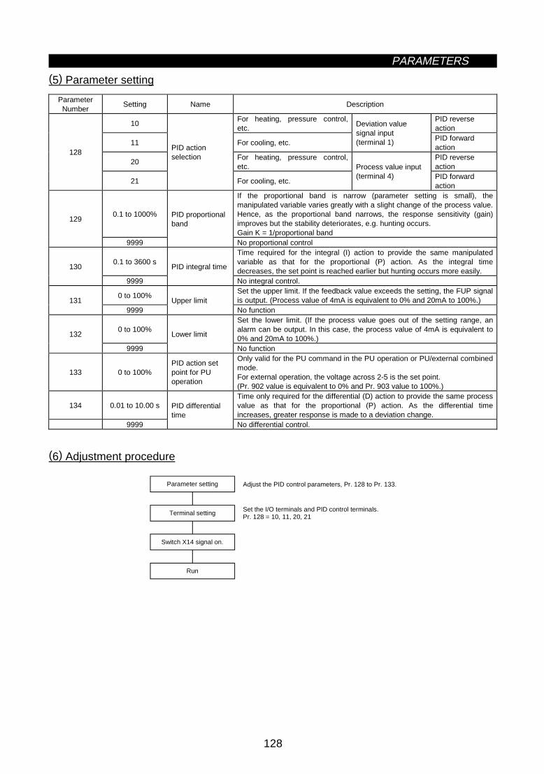
PARAMETERS
128
(5) Parameter setting
ParameterNumber
Setting Name Description
10For heating, pressure control,etc.
PID reverseaction
11 For cooling, etc.
Deviation valuesignal input(terminal 1) PID forward
action
20For heating, pressure control,etc.
PID reverseaction
128
21
PID actionselection
For cooling, etc.
Process value input(terminal 4) PID forward
action
0.1 to 1000%
If the proportional band is narrow (parameter setting is small), themanipulated variable varies greatly with a slight change of the process value.Hence, as the proportional band narrows, the response sensitivity (gain)improves but the stability deteriorates, e.g. hunting occurs.Gain K = 1/proportional band
129
9999
PID proportionalband
No proportional control
0.1 to 3600 sTime required for the integral (I) action to provide the same manipulatedvariable as that for the proportional (P) action. As the integral timedecreases, the set point is reached earlier but hunting occurs more easily.
130
9999
PID integral time
No integral control.
0 to 100%Set the upper limit. If the feedback value exceeds the setting, the FUP signalis output. (Process value of 4mA is equivalent to 0% and 20mA to 100%.)131
9999Upper limit
No function
0 to 100%Set the lower limit. (If the process value goes out of the setting range, analarm can be output. In this case, the process value of 4mA is equivalent to0% and 20mA to 100%.)
132
9999
Lower limit
No function
133 0 to 100%PID action setpoint for PUoperation
Only valid for the PU command in the PU operation or PU/external combinedmode.For external operation, the voltage across 2-5 is the set point.(Pr. 902 value is equivalent to 0% and Pr. 903 value to 100%.)
134 0.01 to 10.00 sTime only required for the differential (D) action to provide the same processvalue as that for the proportional (P) action. As the differential timeincreases, greater response is made to a deviation change.
9999
PID differentialtime
No differential control.
(6) Adjustment procedure
Set the I/O terminals and PID control terminals.Pr. 128 = 10, 11, 20, 21
Parameter setting
Terminal setting
Switch X14 signal on.
Run
Adjust the PID control parameters, Pr. 128 to Pr. 133.

PARAMETERS
129
(7) Calibration example
(A detector of 4mA at 0°C and 20mA at 50°C is used to adjust the room temperature to 25°C under PIDcontrol.The set point is given to across inverter terminals 2-5 (0-5V).)
Yes
No
*When calibration is required, use Pr. 902 to Pr. 905 to calibrate the detector output and set point setting input in the PU mode during an inverter stop.
START
Determine the set point.
Determine the set point of theitem to be adjusted.
Convert the set point into %.
Calculate the ratio of the setpoint to the detector output.
Make calibration.
Set the set point.
Enter a voltage to acrossterminals 2-5 according tothe set point (%).
Operation
Set the proportional band andintegral time to slightly higher values and the differential time toa slightly lower value, and switchon the start signal.
Is the process value steady?
Adjust parameters.
Set the proportional band andintegral time to slightly higher values and set the differential timeto a slightly lower value to stabilize the process value.
END
Optimize parameters.
While the process value is steady,the proportional band and integral time may be reduced and thedifferential time increasedthroughout the operation.
xxxxxxSet the room temperature to 25°C. Set Pr. 128 and switch on the X14 signal to enable PID control.
xxxxxxDetector specifications When the detector used has the specifications that 0°C is equivalent to 4mA and 50°C to 50mA, the set point of 25°C is 50% because 4mA is equivalent to 0% and 20mA to 100%.
xxxxxxWhen the set point setting input (0 to 5V) and detector output (4 to 20mA) must be calibrated, make the following calibration*.
xxxxxxSet point = 50% Since the specifications of terminal 2 are such that 0% is equivalent to 0V and 100% to 5V, enter 2.5V into terminal 2.
xxxxxxFor PU operation, set the set point (0 to 100%) in Pr. 133. During operation, set the proportional band and integral time to slightly higher values and set the differential time to a slightly lower value. In accordance with the system operation, reduce the proportional band and integral time and increase the differential time.

PARAMETERS
130
<Set point input calibration>
1. Apply the input voltage of 0% set point setting (e.g. 0V) to across terminals 2-5.2. Make calibration using Pr. 902. At this time, enter the frequency which should be output by the inverter at
the deviation of 0% (e.g. 0Hz).3. Apply the voltage of 100% set point setting (e.g. 5V) to across terminals 2-5.4. Make calibration using Pr. 903. At this time, enter the frequency which should be output by the inverter at
the deviation of 100% (e.g. 60Hz).
<Detector output calibration>
1. Apply the output current of 0% detector setting (e.g. 4mA) to across terminals 4-5.2. Make calibration using Pr. 904.3. Apply the output current of 100% detector setting (e.g. 20mA) to across terminals 4-5.4. Make calibration using Pr. 905.Note: The frequencies set in Pr. 904 and Pr. 905 should be the same as set in Pr. 902 and Pr. 903. The
results of the above calibration are as shown below:
100
0
0 5 (V)
%
[Set point setting]
100
0
0 20 (mA)
%
4
[Detection value]
60
0
0 100 Deviation (%)
[Manipulated variable]Manipulatedvariable (Hz)
Note: 1. If the multi-speed (RH, RM, RL) signal or jog operation (jog) signal is entered with the X14 signalon, PID control is stopped and multi-speed or jog operation is started.
2. When "20" or "21" is set in Pr. 128, note that the input across inverter terminals 1-5 is added tothe set point across terminals 2-5.
3. When "5" (programmed operation mode) is selected for Pr. 79, PID control operation cannot beperformed. In this setting, programmed operation is performed.
4. When "6" (switch-over mode) is selected for Pr. 79, PID is made invalid.5. When "9999" is set in Pr. 22, the stall prevention level is the value entered from terminal 1. When
using terminal 1 as the edit input terminal for PID, therefore, set a value other than "9999" inPr. 22.
6. When "1" (online auto tuning) is selected for Pr. 95, PID control is made invalid.7. When the terminal functions are changed using Pr. 180 to Pr. 186 and/or Pr. 190 to Pr. 195, the
other functions may be affected. Confirm the functions of the corresponding terminals beforemaking settings.

PARAMETERS
131
Pr. 11 "DC dynamic brake operation time"Pr. 17 "MRS input selection"Pr. 57 "restart coasting time"Pr. 58 "restart cushion time"Pr. 180 to Pr. 186 (input terminal function selection)Pr. 190 to Pr. 195 (output terminal function selection)
Related parametersz Commercial power supply-inverter switch-over function (Pr. 135 to Pr. 139)
Pr. 135 "commercial power supply-inverterswitch-over sequence output terminal selection"
Pr. 136 "MC switch-over interlock time"
Pr. 137 "start waiting time"
Pr. 138 "commercial power supply-inverterswitch-over selection at alarm occurrence"
Pr. 139 "automatic inverter-commercial powersupply switch-over frequency"
The inverter contains a complicated sequence circuit for commercial power supply-inverter operation switch-over. Hence, the magnetic contactors for switch-over can be interlocked easily by merely entering the start,stop or automatic switch-over select signal.
ParameterNumber
Factory Setting Setting Range Remarks
135 0 0, 1136 0.1 sec. 0 to 100.0 sec.137 0.5 sec. 0 to 100.0 sec.138 0 0,1
139 9999 0 to 60.0Hz, 99999999: No automatic
switch-over
(1) Wiring example
Sink logic, Pr. 185 = 7, Pr. 186 = 6, Pr. 192 = 17, Pr. 193 = 18, Pr. 194 = 19
MC1R ⟨L1⟩S ⟨L2⟩T ⟨L3⟩
STF
R1 ⟨L11⟩
S1 ⟨L21⟩
CSMRS
RES
SD
1025
UVW
MC2
×MC3
IM
IPF
OL
SE
*1
*1
*1
*2MC3
MC2
DC24V
MC1
FU
NFB
MC2
MC3*3OH
SU
IPF
OL
FU
SE
DC24V
External thermal relayReset
Frequency setting signal
Externalthermal relay
Signal set in Pr. 190 to Pr. 195
*3. The terminals used depend on the Pr. 180 to Pr. 186 settings.
Note: This switch-over function is used in the external operation mode. Always connect terminals R1, S1 (L11, L21) to a different power supply (power supply different from the one for MC1) to ensure proper operation. MC2 and MC3 must be mechanically interlocked.
*1. Note the sequence output terminal capacities. The terminals used depend on the Pr. 190 to Pr. 194 settings.
Output Terminal Capacity Permissible Output Terminal Load
Inverter's open collector outputs(IPF, OL, FU)
24VDC 0.1A
FR-A5AR (option output)230VAC 0.3A30VDC 0.3A
*2. When connecting an AC power supply, connect the FR-A5AR option and use the contact output. When connecting a DC power supply, install the following protective diode.
Inverter
Operation interlock
Inverter start (forward rotation)Inverter-commercial power supply switch-over

PARAMETERS
132
· Roles of the magnetic contactors (MC1, MC2, MC3)
MagneticContactor
Place of Installation Role
MC1Between power supply andinverter
Normally shorted with the following exception:Opened only when an inverter fault occurs (shorted again by resetting)
MC2 Between power supply and motor
Shorted for commercial power supply operation, opened for inverteroperationShorted when an inverter fault occurs (selected with parameter, exceptfor external thermal relay operation)
MC3 Between inverter output and motorShorted for inverter operation, opened for commercial power supplyoperationOpened when an inverter fault occurs
<I/O signals>
1) When this function is used (Pr. 135 = "1"), the input signals are switched on-off as indicated below:
MC Operation (: ON, ×: OFF)Signal Terminal Used Function On-Off
MC1 MC2 MC3
MRS MRSOperationenable/disable selection
Commercial power supply-inverter operation enable............................ONCommercial power supply-inverter operation disable............................OFF
×
Unchanged
CSDepending on
Pr. 180 to Pr.186
Inverter-commercialpower supply switch-over
Inverter operation .ONCommercial power supplyoperation..............OFF
×
×
STF(STR)
STF(STR)
Inverter operationcommand (invalid forcommercial powersupply) (Note)
Forward (reverse) rotation............................ONStop .....................OFF
×
×
OHDepending on
Pr. 180 to Pr.186External thermal relayinput
Motor normal........ONMotor fault ............OFF
××
×
RES RESOperating conditioninitialization
Initialization ..........ONNormal operation .OFF
Unchanged
×
Unchanged
Note: · In the above MC Operation field, [-] indicates that MC1 is on, MC2 is off and MC3 is on in inverteroperation and MC1 is on, MC2 is off and MC3 is off in commercial power supply operation.[Unchanged] indicates that the status before signal-on or -off is held.
· The CS signal only functions when the MRS signal is on. STF (STR) only functions when MRS andCS are on.
· MC1 switches off when an inverter fault occurs.· If the MRS signal is not switched on, neither commercial power supply nor inverter operation can be
performed.
2) The output signals are output as follows:
Signal Terminal Used DescriptionMC1 MC1's operation signal is outputMC2 MC2's operation signal is outputMC3
Depending on Pr. 190to Pr. 195
MC3's operation signal is output

PARAMETERS
133
(2) Parameter setting
ParameterNumber
Name Setting Description
0Sequence output is not provided. (Pr. 136, Pr. 137, Pr. 138 and Pr. 139settings are ignored.)
135
Commercial powersupply-inverterswitch-oversequence outputterminal selection
1
Sequence output is provided.When MC1 to MC3 are assigned with Pr. 190 to Pr. 195 (output terminalfunction selection), open collector outputs are provided. When they are notassigned, relay outputs are provided from the FR-A5AR (option).
136MC switch-overinterlock time
0 to 100.0 sSets the MC2 and MC3 operation interlock time.
137 Start waiting time 0 to 100.0 sSet a slightly longer (about 0.3 to 0.5 s) value than the time from when theON signal enters inverter operation MC3 to when it actually switches on.
0Stops inverter operation and coasts the motor.The inverter stops when an inverter fault occurs (both MC2 and MC3 switchoff).
138
Commercial powersupply-inverterswitch-over selectionat alarm occurrence 1
Stops inverter operation and automatically switches inverter operation tocommercial power supply operation.When an inverter fault occurs, inverter operation is automatically switched tocommercial power supply operation (MC2: ON, MC3: OFF).
0 to 60.0Hz
The motor is started and run by the inverter up to the set frequency, andwhen the output frequency reaches or exceeds the set frequency, inverteroperation is automatically switched to commercial power supply operation.Start and stop are controlled by the inverter operation command (STF orSTR).
139
Automatic inverter-commercial powersupply switch-overfrequency
9999 Automatic switch-over is not done.
Note: 1. Pr. 139 functions when Pr. 135 setting is other than "0".2. When the motor started by the inverter reaches the automatic switch-over frequency, inverter
operation is switched to commercial power supply operation. If the inverter's run command value isthen lowered to or below the switch-over frequency, commercial power supply operation is notautomatically switched to inverter operation.Switch off the inverter operation command signal (STF or STR) to switch commercial power supplyoperation to inverter operation and decelerate the motor to a stop.
<Operation sequence>ON
OFF
ON
OFF
ON
OFF
ON
OFF
(MRS)
(STF)
(CS)
ON
OFF(MC1)
ON
OFF(MC3)
ON
OFF(MC2)
A A,B AC,D
A C,DB Each timerA: Pr. 136 (MC switch-over interlock time)B: Pr. 137 (MC start waiting time)C: Pr. 57 (reset time)D: Pr. 58 (switch-over cushion time)
Power
Operation interlock
Inverter operation command
Inverter-commercial power supply switch-over
Commercial power supply-inverter switch-over
Commercial power supply-inverter switch-over
Commercial power supply-inverter switch-over
Each timer
Operating status(Motor speed)
Off for inverter fault only
Operation command
Actual operation (Note)
Coast to stop
Commercial power supply stop
Inverteroperation
Coasting
Commercial powersupply operation
Coasting Inverter operation
Stop Inverter operation
ON: Operation enable
OFF: Operation disable
ON: Forward rotation
ON: Inverter operation
OFF: Stop
OFF: Commercial power supply operation
Note: Indicates a delay until MC switches on.

PARAMETERS
134
(3) Operation procedure
1) Operation procedure for runningOperation pattern
Pr. 135 = "1" (inverter's open collector output terminals) Pr. 136 = "2.0 s" Pr. 137 = "1.0 s" (Set the value equal to or longer than the time from when MC3 switches on actually until the inverter and motor are connected. If it is shorter, restart may not function properly. Pr. 57 = "0.5 s" Pr. 58 = "0.5 s" (Always set this parameter when commercial power supply operation is switched to inverter operation.)
Constant-speed operation,commercial power supply operation
Switch power on.
Set parameters.
Start, inverter operation
Deceleration (stop), inverter operation
2) Signal on-off after parameter setting
MRS CS STF MC1 MC2 MC3 Remarks
Power onOFF
(OFF)OFF
(OFF)OFF
(OFF)OFF ON
(OFF ON)OFF
(OFF)OFF ON
(OFF ON)External operation mode(PU operation mode)
At start(Inverter)
OFF ON OFF ON OFF ON ON OFF ON
Constant speed(Commercialpower supply)
ON ON OFF ON ON OFF ON ON OFF
After MC3 switches off,MC2 switches on.(Motor coasts during thisperiod.)Waiting time 2 seconds.
Switched toinverteroperation fordeceleration(Inverter)
ON OFF ON ON ON ON OFF OFF ON
After MC2 switches off,MC3 switches on.(Motor coasts during thisperiod.)Waiting time 4 seconds.
Stop ON ON ON OFF ON OFF ON
Note: 1. This function is only activated when R1 and S1 are connected to a different power supply (powersupply which is not connected to MC1).
2. This function is only valid in the external operation or PU (speed command) and external (runcommand) operation mode when the Pr. 135 value is other than "0". When the Pr. 135 value isother than "0" in the operation mode other than the above, MC1 and MC3 switch on.
3. MC3 is on when the MRS and CS signals are on and STR is off, but when the motor run by thecommercial power supply was coasted to a stop at the last time, it restarts after the time set inPr. 137 has elapsed.
4. Inverter operation is enabled when the MRS, STF and CS signals switch on. In other cases (MRSis on), commercial power supply operation is performed.
5. When the CS signal is switched off, the motor is switched over to commercial power supplyoperation. Note that when the STF (STR) signal is switched off, the motor is decelerated to a stopby the inverter.
6. When both MC2 and MC3 are off and MC2 or MC3 is then switched on, the motor restarts afterthe waiting time set in Pr. 136 has elapsed.
7. If the Pr. 135 setting is other than 0, the Pr. 136 and Pr. 137 settings are ignored in the PUoperation mode.Also, the inverter's input terminals (STF, CS, MRS, OH) return to their ordinary functions.
8. When the commercial power supply-inverter switch-over sequence is selected, the PU operationinterlock function (Pr. 79 = 7) is not activated if it has been set.
9. When the terminal functions are changed using Pr. 180 to Pr. 186 and/or Pr. 190 to Pr. 195, theother functions may be affected. Confirm the functions of the corresponding terminals beforemaking settings.
Pr. 140 to Pr. 143 Î Refer to Pr. 29.
Pr. 144 Î Refer to Pr. 37.
Pr. 148, Pr. 149 Î Refer to Pr. 22.

PARAMETERS
135
Pr. 190 to Pr. 195 (output terminal function selection)
Related parametersz Output current detection function (Pr. 150, Pr. 151)
Pr. 150 "output current detection level"
Pr. 151 "output current detection time"
z If the output current remains higher than the Pr. 150 setting during inverter operation for longer than thetime set in Pr. 151, the output current detection signal (Y12) is output from the inverter's open collectoroutput terminal.(Use any of Pr. 190 to Pr. 195 to assign the terminal used for Y12 signal output.)
ParameterNumber
Factory Setting Setting Range
150 150% 0 to 200.0%151 0 0 to 10 s
Pr.151
Pr.150
OFF ON OFF
Minimum 100ms
Time (t)
Output currentdetection signal
Output (I)
<Setting>
Refer to the following list and set the parameters:
Parameter Number Description
150Set the output current detection level.100% is the rated inverter current.
151Set the output current detection time. Set a period of time from when the output current rises to or above thePr. 150 setting to when the output current detection signal (Y12) is output.
Note: 1. Once switched on, the output current detection signal is held on for at least 100ms.2. This function is also valid during execution of the online or offline auto tuning.3. When the terminal functions are changed using Pr. 190 to Pr. 195, the other functions may be
affected. Confirm the functions of the corresponding terminals before making settings.
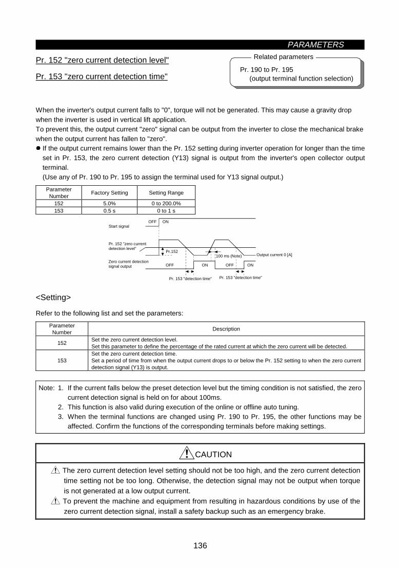
PARAMETERS
136
Pr. 190 to Pr. 195 (output terminal function selection)
Related parametersz Zero current detection (Pr. 152, Pr. 153)
Pr. 152 "zero current detection level"
Pr. 153 "zero current detection time"
When the inverter's output current falls to "0", torque will not be generated. This may cause a gravity dropwhen the inverter is used in vertical lift application.To prevent this, the output current "zero" signal can be output from the inverter to close the mechanical brakewhen the output current has fallen to "zero".z If the output current remains lower than the Pr. 152 setting during inverter operation for longer than the time
set in Pr. 153, the zero current detection (Y13) signal is output from the inverter's open collector outputterminal.(Use any of Pr. 190 to Pr. 195 to assign the terminal used for Y13 signal output.)
ParameterNumber
Factory Setting Setting Range
152 5.0% 0 to 200.0%153 0.5 s 0 to 1 s
Output current 0 [A]
OFF ON
OFF ON
Pr.152
OFF ON
100 ms (Note)
Start signal
Pr. 152 "zero currentdetection level"
Zero current detectionsignal output
Pr. 153 "detection time" Pr. 153 "detection time"
<Setting>
Refer to the following list and set the parameters:
ParameterNumber
Description
152Set the zero current detection level.Set this parameter to define the percentage of the rated current at which the zero current will be detected.
153Set the zero current detection time.Set a period of time from when the output current drops to or below the Pr. 152 setting to when the zero currentdetection signal (Y13) is output.
Note: 1. If the current falls below the preset detection level but the timing condition is not satisfied, the zerocurrent detection signal is held on for about 100ms.
2. This function is also valid during execution of the online or offline auto tuning.3. When the terminal functions are changed using Pr. 190 to Pr. 195, the other functions may be
affected. Confirm the functions of the corresponding terminals before making settings.
CAUTION
The zero current detection level setting should not be too high, and the zero current detectiontime setting not be too long. Otherwise, the detection signal may not be output when torqueis not generated at a low output current.
To prevent the machine and equipment from resulting in hazardous conditions by use of thezero current detection signal, install a safety backup such as an emergency brake.

PARAMETERS
137
Pr. 14 "load pattern selection"Pr. 44 to Pr. 49 (second function selection)Pr. 81 "number of motor poles"Pr. 180 to Pr. 186 (input terminal function selection)
Related parameters
Pr. 22 "stall prevention operation level"Pr. 23 "stall prevention operation level at
double speed"Pr. 47 "second stall prevention operation
current"Pr. 48 "second stall prevention operation
frequency"Pr. 114 "third stall prevention operation
current"Pr. 115 "third stall prevention operation
frequency"Pr. 154 "voltage reduction selection
during stall prevention operation"Pr. 157 "OL signal output waiting time"
Related parameters
Pr. 154 Î Refer to Pr. 22.z RT signal activated condition selection (Pr. 155)
Pr. 155 "RT signal activated condition selection"
z Set the condition of activating the RT terminal to select the second control functions by switching on-off theRT signal.
ParameterNumber
Factory Setting Setting Range
155 0 0, 10
<Setting>
Refer to the following table and set the parameter:
Pr. 155 Setting Description
0Made valid immediately by switching the RT signalon-off.
10Made valid only when the RT signal is on at constantspeed.(Invalid during acceleration/deceleration)
z Stall prevention function and current limit function (Pr. 156)
Pr. 156 "stall prevention operation selection"
Stall prevention and fast-response current limit can be disabled and the OL signal output delayed.
ParameterNumber
Factory Setting Setting Range
156 0 0 to 31, 100, 101

PARAMETERS
138
<Setting>
Refer to the following table and set the parameter as required:
Stall Prevention...Activatedz...Not activated
Pr. 156 Setting
Fast-ResponseCurrent Limit
...Activatedz...Not activated Acceleration Constant speed Deceleration
OL Signal Output...Operation continuedz...Operation not
continued (Note 1)0
1 z
2 z
3 z z
4 z
5 z z
6 z z
7 z z z
8 z
9 z z
10 z z
11 z z z
12 z z
13 z z z
14 z z z
15 z z z z
16 z
17 z z
18 z z
19 z z z
20 z z
21 z z z
22 z z z
23 z z z z
24 z z
25 z z z
26 z z z
27 z z z z
28 z z z
29 z z z z
30 z z z z
31 z z z z z
Driving 100
Regenerative z z z z
Driving z 101
Regenerative z z z z
Note 1: When "Operation not continued for OL signal output" is selected, the "E.OLT" alarm code(stopped by stall prevention) is displayed and operation stopped.(Alarm stop display "E.OLT")
Note 2: If the load is heavy, the lift is predetermined, or the acceleration/deceleration time is short, thestall prevention may be activated and the motor not stopped in the presetacceleration/deceleration time. Therefore, set optimum values to the Pr. 156 stall preventionoperation level.(When the output voltage reduces during stall prevention operation, an overcurrent trip will be lessliable to occur but the torque decreases. Set "0" in Pr. 154 when the torque may be reduced.)
CAUTION
Always perform test operation.Stall prevention operation performed during acceleration may increase the acceleration time.Stall prevention operation performed during constant speed may cause sudden speedchanges.Stall prevention operation performed during deceleration may increase the deceleration time,increasing the deceleration distance.

PARAMETERS
139
Pr. 190 "RUN terminal function selection"Pr. 191 "SU terminal function selection"Pr. 192 "IPF terminal function selection"Pr. 193 "OL terminal function selection"Pr. 194 "FU terminal function selection"Pr. 195 "ABC terminal function selection"
Related parametersz OL signal output timer (Pr. 157)
Pr. 157 "OL signal output waiting time"
Use this parameter to set whether the overload alarm signal (OL signal) is output immediately or a presetperiod of time after occurrence of an overload status.
ParameterNumber
Factory Setting Setting Range Remarks
157 0 0 to 25 s, 9999 9999: No signal output
Set time t (seconds)
Overload status (OL output)
OL output signal
<Setting>
Refer to the following table and set the parameter:
Pr. 157 Setting Description0 Output immediately.
0.1 to 25 Output after the set time t (seconds) have elapsed.9999 Overload alarm signal is not output.
Pr. 158 Î Refer to Pr. 54.

PARAMETERS
140
z User group selection (Pr. 160, Pr. 173 to Pr. 176)
Pr. 160 "user group read selection"
Pr. 173 "user group 1 registration"
Pr. 174 "user group 1 deletion"
Pr. 175 "user group 2 registration"
Pr. 176 "user group 2 deletion"From among all parameters, a total of 32 parameters can be registered to two different user groups.The registered parameters may only be accessed for reading and writing.Other parameters than those registered to the user groups cannot be read.
ParameterNumber
Factory Setting Setting Range Remarks
160 0 0, 1, 10, 11173 0 0 to 999174 0 0 to 999, 9999 9999: Batch deletion175 0 0 to 999176 0 0 to 999, 9999 9999: Batch deletion
<Examples of use>(1) Parameter registration to user group (when registering Pr. 3 to user group 1)
FR-DU04 CONTROL PANEL
Hz
MON EXT PU
AV
REV FWD
FR-DU04 CONTROL PANEL
Hz
MON EXT PU
AV
REV FWD
FR-DU04 CONTROL PANEL
Hz
MON EXT PU
AV
REV FWD
FR-DU04 CONTROL PANEL
Hz
MON EXT PU
AV
REV FWD
FR-DU04 CONTROL PANEL
Hz
MON EXT PU
AV
REV FWD
Pr. 173 reading
1) 2) 3) 4) 5)
SET SET
1.5 seconds
The number of parameters registered for user setting appears.
Using the [UP/DOWN] key, choose the parameter number to be registered.
Pr. 3 is registered to user group 1.
Using the [UP/DOWN] key, move to the next parameter to be registered. Using the [SET] key, make registration.
.....
Flickering
.....
.....
.....
(2) Parameter deletion from user group (when deleting Pr. 5 from user group 1)
FR-DU04 CONTROL PANEL
Hz
MON EXT PU
AV
REV FWD
FR-DU04 CONTROL PANEL
Hz
MON EXT PU
AV
REV FWD
FR-DU04 CONTROL PANEL
Hz
MON EXT PU
AV
REV FWD
FR-DU04 CONTROL PANEL
Hz
MON EXT PU
AV
REV FWD
FR-DU04 CONTROL PANEL
Hz
MON EXT PU
AV
REV FWD
Pr. 174 reading
1) 2) 3) 4) 5)
SET SET
1.5 seconds
The number of parameters registered for user setting appears.
Using the [UP/DOWN] key, choose the parameter number to be deleted.
Pr. 5 is deleted from user group 1.
Using the [UP/DOWN] key, choose the parameter to be deleted. Using the [SET] key, make deletion.
.....
Flickering
.....
.....
.....
(3) By setting the required value in Pr. 160, make the user groups valid or invalid.
Pr. 160 Setting Description0 All parameters can be accessed for reading and writing (Factory setting)1 Parameters registered to user group 1 may only be accessed for reading and writing.10 Parameters registered to user group 2 may only be accessed for reading and writing.11 Parameters registered to user groups 1 and 2 may only be accessed for reading and writing.
Note: 1. Pr. 77, Pr. 160 and Pr. 991 values can always be read independently of the user group setting.2. When Pr. 173 or Pr. 174 is read, the number of parameters registered to user group 1 appears.
When Pr. 175 or Pr. 176 is read, the number of parameters registered to user group 2 appears.3. "0" set in the second digit of the 2-digit Pr. 160 setting is not displayed. However, it is displayed
when "0" is set in the first digit only.4. When "9999" is set in Pr. 174 or Pr. 176, the parameters registered to the corresponding user
group is batch-deleted.
Pr. 162 to Pr. 165 Î Refer to Pr. 57.

PARAMETERS
141
Pr. 52 "DU/PU main display data selection"
Related parameterz Watt-hour meter clear/actual operation hour meter clear (Pr. 170, Pr. 171)
Pr. 170 "watt-hour meter clear"
Pr. 171 "actual operation hour meter clear"
You can clear the watt-hour value and actual operation hour monitoring function.
ParameterNumber
Factory Setting Setting Range
170 0 0171 0 0
<Setting>
Write "0" in the parameters to clear the watt-hour value and actual operation hour.
Pr. 173 to Pr. 176 Î Refer to Pr. 160.
z Input terminal function selection (Pr. 180 to Pr. 186)
Pr. 180 "RL terminal function selection"
Pr. 181 "RM terminal function selection"
Pr. 182 "RH terminal function selection"
Pr. 183 "RT terminal function selection"
Pr. 184 "AU terminal function selection"
Pr. 185 "JOG terminal function selection"
Pr. 186 "CS terminal function selection"
Use these parameters to select/change the input terminal functions.
ParameterNumber
TerminalSymbol
Factory Setting Factory-Set Terminal Function Setting Range
180 RL 0 Low-speed operation command (RL) 0 to 99, 9999181 RM 1 Middle-speed operation command (RM) 0 to 99, 9999182 RH 2 High-speed operation command (RH) 0 to 99, 9999183 RT 3 Second function selection (RT) 0 to 99, 9999184 AU 4 Current input selection (AU) 0 to 99, 9999185 JOG 5 Jog operation selection (JOG) 0 to 99, 9999
186 CS 6Automatic restart after instantaneouspower failure selection (CS)
0 to 99, 9999

PARAMETERS
142
<Setting>
Refer to the following list and set the parameters:
SettingSignalName
Functions Relevant Parameters
Pr. 59 = 0Low-speed operation command Pr. 4 to Pr. 6
Pr. 24 to Pr. 27Pr. 232 to Pr. 239
Pr. 59 = 1, 2 * Remote setting (acceleration) Pr. 59
Pr. 79 = 5 *Programmed operation groupselection
Pr. 79, Pr. 200, Pr. 201 to Pr. 210, Pr.211 to Pr. 220, Pr. 221 to Pr. 230, Pr.231
0 RL
Pr. 270 = 1, 3 * Stop-on-contact selection 0 Pr. 270, Pr. 275, Pr. 276
Pr. 59 = 0 Middle-speed operation command Pr. 4 to Pr. 6, Pr. 24 to Pr. 27, Pr. 232 toPr. 239
Pr. 59 = 1, 2 * Remote setting (deceleration) Pr. 591 RM
Pr. 79 = 5 *Programmed operation groupselection
Pr. 79, Pr. 200, Pr. 201 to Pr. 210, Pr.211 to Pr. 220, Pr. 221 to Pr. 230, Pr.231
Pr. 59 = 0 High-speed operation command Pr. 4 to Pr. 6, Pr. 24 to Pr. 27,Pr. 232 to Pr. 239
Pr. 59 = 1, 2 * Remote setting (setting clear) Pr. 592 RH
Pr. 79 = 5 *Programmed operation groupselection
Pr. 79, Pr. 200, Pr. 201 to Pr. 210, Pr.211 to Pr. 220, Pr. 221 to Pr. 230, Pr.231
Second function selection Pr. 44 to Pr. 503 RT
Pr.270 = 1, 3 * Stop-on-contact selection 1 Pr. 270, Pr. 275, Pr. 2764 AU Current input selection Refer to page 105 JOG Jog operation selection Pr. 15, Pr. 166 CS Automatic restart after instantaneous power failure selection Pr. 57, Pr. 58, Pr. 162 to Pr. 165
7 OH
External thermal relay input**The externally provided overheat protection thermal relay,motor-embedded temperature relay or the like is operated tostop the inverter.
Refer to page 174
8 REX 15-speed selection (combination with RL, RM, RH)Pr. 4 to Pr. 6, Pr. 24 to Pr. 27,Pr. 232 to Pr. 239
9 X9 Third function Pr. 110 to Pr. 11610 X10 FR-HC connection (inverter operation enable) Pr. 30, Pr. 7011 X11 FR-HC connection (instantaneous power failure detection) Pr. 30, Pr. 7012 X12 PU operation external interlock Pr. 7913 X13 External DC dynamic braking start Pr. 10 to Pr. 1214 X14 PID control valid terminal Pr. 128 to Pr. 13415 BRI Brake opening completion signal Pr. 278 to Pr. 28516 X16 PU-external operation switch-over Pr. 7917 X17 Load pattern selection forward/reverse rotation boost Pr. 1418 X18 Advanced magnetic flux vector-V/F switch-over Pr. 80, Pr. 81, Pr. 8919 X19 Load torque high-speed frequency Pr. 271 to Pr. 27420 X20 S-pattern acceleration/deceleration C switch-over terminal
(only when FR-A5AP option is fitted)Pr. 380 to Pr. 383
22 X22 Orientation command (Note 11) (only when FR-A5AP optionis fitted)
Pr. 350 to Pr. 369
23 LX Pre-excitation (Note 2) (only when FR-A5AP option is fitted) Pr. 80, Pr.81, Pr. 359, Pr. 369, Pr. 3709999 No function
*: When Pr. 59 = "1 or 2", Pr. 79 = "5", and Pr. 270 = "1 or 3", the functions of the RL, RM, RH and RT signals change as listed above.**: Operated when the relay contact "opens".

PARAMETERS
143
Note: 1. One function can be assigned to two or more terminals. In this case, the terminal inputs areOR’ed.
2. The speed command priorities are higher in order of jog, multi-speed setting (RH, RM, RL) andAU.
3. When HC connection (inverter operation enable signal) is not selected, the MRS terminal sharesthis function.
4. When advanced magnetic flux vector-V/F switch-over and load pattern selection forward/reverserotation boost are not selected, the second functions (RT) share these functions.
5. Use common terminals to assign programmed operation group selection, multi-speeds (7speeds) and remote setting. They cannot be set individually.(Common terminals are used since these functions are designed for speed setting and need notbe set at the same time.)
6. Stop-on-contact control selection, Pr. 270 = "1 or 3", shares RT with multi-speed setting (lowspeed), and its allocation cannot be changed.
7. When FR-HC connection inverter operation enable (X10) signal is not assigned, the MRSterminal shares this function.
8. When "7" is set in Pr. 79 and the PU operation external interlock (X12) signal is not assigned, theMRS signal acts as this function.
9. When the load pattern selection forward/reverse rotation boost (X17) signal is not assigned, theRT signal shares this function.
10. When advanced magnetic flux vector-V/F switch-over (X18) signal is not assigned, the RT signalshares this function.
11. When a stop position is entered externally for orientation control, the FR-A5AX (12-bit digitalinput) is required.
12. Made valid when vector control servo lock is set valid.

PARAMETERS
144
Pr. 76 "operation mode selection"
Related parameterz Output terminal function selection (Pr. 190 to Pr. 195)
Pr. 190 "RUN terminal function selection"
Pr. 191 "SU terminal function selection"
Pr. 192 "IPF terminal function selection"
Pr. 193 "OL terminal function selection"
Pr. 194 "FU terminal function selection"
Pr. 195 "ABC terminal function selection"
You can change the functions of the open collector and contact output terminals.
ParameterNumber
TerminalSymbol
Factory SettingFactory-Set Terminal
FunctionSetting Range
190 RUN 0 Inverter running 0 to 199, 9999191 SU 1 Up to frequency 0 to 199, 9999
192 IPF 2Instantaneous powerfailure/undervoltage
0 to 199, 9999
193 OL 3 Overload alarm 0 to 199, 9999194 FU 4 Frequency detection 0 to 199, 9999195 A, B, C 99 Alarm output 0 to 199, 9999
<Setting>
Refer to the following table and set the parameters:
SettingPositive
logicNegative
logic
SignalName
Function OperationRelated
parameter
0 100 RUN Inverter runningOutput during operation when the inverter outputfrequency rises to or above the starting frequency.
1 101 SU Up to frequencyRefer to Pr. 41 "up-to-frequency sensitivity". (Note2)
Pr. 41
2 102 IPFInstantaneous power failure orundervoltage
Output when an instantaneous power failure orundervoltage occurs.
3 103 OL Overload alarm
Output while stall prevention function is activated. Pr. 22, Pr. 23,Pr. 66, Pr. 148,Pr.1, Pr. 149,
Pr. 154
4 104 FU Output frequency detectionRefer to Pr. 42, Pr. 43 (output frequencydetection).
Pr. 42, Pr. 43
5 105 FU2Second output frequencydetection
Refer to Pr. 50 (second output frequencydetection).
Pr. 50
6 106 FU3Third output frequencydetection
Refer to Pr. 116 (third output frequencydetection).
Pr. 116
7 107 RBP Regenerative brake pre-alarmOutput when 85% of the regenerative brake dutyset in Pr. 70 is reached.
Pr. 70
8 108 THPElectronic overcurrentprotection pre-alarm
Output when the cumulative electronicovercurrent protection value reaches 85% of thepreset level.
Pr. 9
9 109 PRG Programmed modeOutput in the programmed mode. (Note 3) Pr. 79, Pr. 200
to Pr. 23110 110 PU PU operation mode Output when the PU operation mode is selected. Pr. 17 = 0 to 3
11 111 RY Inverter operation readyOutput when the inverter can be started byswitching the start signal on or while it is running.
12 112 Y12 Output current detectionRefer to Pr. 150 and Pr. 151 (output currentdetection).
Pr. 150, Pr. 151
13 113 Y13 Zero current detectionRefer to Pr. 152 and Pr. 153 (zero currentdetection).
Pr. 152, Pr. 153
14 114 FDN PID lower limit15 115 FUP PID upper limit
16 116 RLPID forward-reverse rotationoutput
Refer to Pr. 128 to Pr. 134 (PID control).Pr. 128 toPr. 134
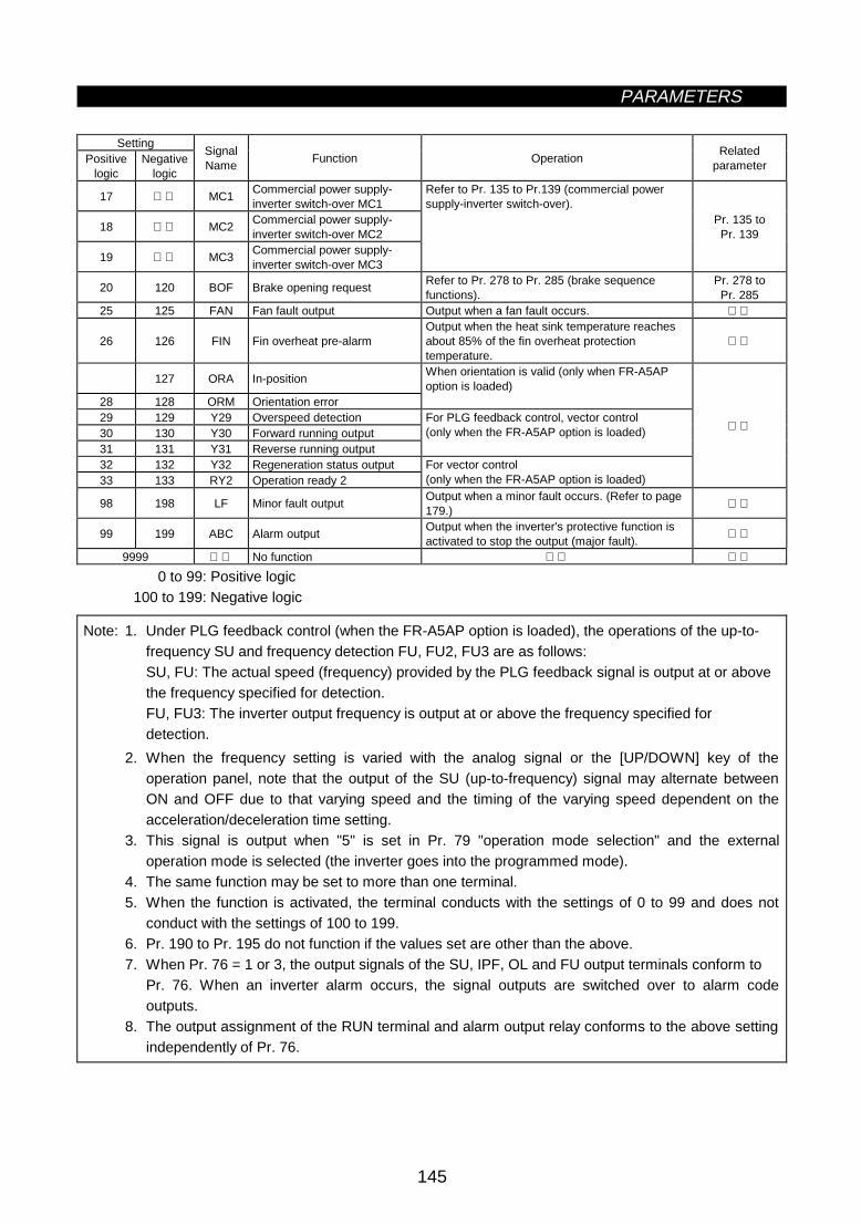
PARAMETERS
145
SettingPositive
logicNegative
logic
SignalName
Function OperationRelated
parameter
17 MC1Commercial power supply-inverter switch-over MC1
18 MC2Commercial power supply-inverter switch-over MC2
19 MC3Commercial power supply-inverter switch-over MC3
Refer to Pr. 135 to Pr.139 (commercial powersupply-inverter switch-over).
Pr. 135 toPr. 139
20 120 BOF Brake opening requestRefer to Pr. 278 to Pr. 285 (brake sequencefunctions).
Pr. 278 toPr. 285
25 125 FAN Fan fault output Output when a fan fault occurs.
26 126 FIN Fin overheat pre-alarmOutput when the heat sink temperature reachesabout 85% of the fin overheat protectiontemperature.
127 ORA In-position
28 128 ORM Orientation error
When orientation is valid (only when FR-A5APoption is loaded)
29 129 Y29 Overspeed detection30 130 Y30 Forward running output31 131 Y31 Reverse running output
For PLG feedback control, vector control(only when the FR-A5AP option is loaded)
32 132 Y32 Regeneration status output33 133 RY2 Operation ready 2
For vector control(only when the FR-A5AP option is loaded)
98 198 LF Minor fault outputOutput when a minor fault occurs. (Refer to page179.)
99 199 ABC Alarm outputOutput when the inverter's protective function isactivated to stop the output (major fault).
9999 No function
0 to 99: Positive logic100 to 199: Negative logic
Note: 1. Under PLG feedback control (when the FR-A5AP option is loaded), the operations of the up-to-frequency SU and frequency detection FU, FU2, FU3 are as follows:SU, FU: The actual speed (frequency) provided by the PLG feedback signal is output at or abovethe frequency specified for detection.FU, FU3: The inverter output frequency is output at or above the frequency specified fordetection.
2. When the frequency setting is varied with the analog signal or the [UP/DOWN] key of theoperation panel, note that the output of the SU (up-to-frequency) signal may alternate betweenON and OFF due to that varying speed and the timing of the varying speed dependent on theacceleration/deceleration time setting.
3. This signal is output when "5" is set in Pr. 79 "operation mode selection" and the externaloperation mode is selected (the inverter goes into the programmed mode).
4. The same function may be set to more than one terminal.5. When the function is activated, the terminal conducts with the settings of 0 to 99 and does not
conduct with the settings of 100 to 199.6. Pr. 190 to Pr. 195 do not function if the values set are other than the above.7. When Pr. 76 = 1 or 3, the output signals of the SU, IPF, OL and FU output terminals conform to
Pr. 76. When an inverter alarm occurs, the signal outputs are switched over to alarm codeoutputs.
8. The output assignment of the RUN terminal and alarm output relay conforms to the above settingindependently of Pr. 76.

PARAMETERS
146
Pr. 77 "parameter write disable selection"
Related parameterz User initial value setting (Pr. 199)
Pr. 199 "user's initial value setting"
Among the parameters, you can set user-only parameter initial values. These values may be set to 16parameters.By performing user clear operation from the operation panel or parameter unit, you can initialize theparameters to the user-set initial values. Note that the parameters of which initial values have not been setare initialized to the factory settings by user clear operation.z You can read the user's initial value list in the help mode of the parameter unit (FR-PU04).
ParameterNumber
Factory Setting Setting Range
199 0 0 to 999, 9999
The read Pr. 199 value is displayed as the number of parameters registered.
<Setting example>
(1) To set "1" in Pr. 7 and "2" in Pr. 8 as user's initial values. (Operation from the FR-DU04)
6) Through the above steps, the initial values of Pr. 7 and Pr. 8 are registered.
1) Set "1" (target initial value) in Pr. 7.
2) Set "2" (target initial value) in Pr. 8.
3) Press the [SET] key to read Pr. 199. The number of parameters having user's initial values are then displayed.
4) Further press the [SET] key for 1.5 seconds. The parameter setting screen is then displayed.
5) Select Pr. 7 and Pr. 8 with the [UP/DOWN] key and press the [SET] key for 1.5 seconds to enter.
The settings of the parameters whose numbers are set in Pr. 199 (i.e. Pr. 7 = 1, Pr. 8 = 2 in the aboveexample) are user's initial values.
(2) Deletion of user's initial valuesBy writing "9999" to Pr. 199 (and pressing the [SET] key for 1.5 seconds), the user's initial valuesregistered are batch-deleted.
Note: 1. When user's initial values for Pr. 902 to Pr. 905 are set, one parameter uses the area of twoparameters for registration.
2. As this setting is concerned with user-cleared initial values, the parameter numbers which cannotbe cleared cannot be set.
3. The operation panel (FR-DU04) cannot be used to refer to user's initial values.4. Values cannot be registered to Pr. 201 to Pr. 231.

PARAMETERS
147
Pr. 76 "alarm code output selection"Pr. 79 "operation mode selection"
Related parametersz Programmed operation function (Pr. 200 to Pr. 231)
Pr. 200 "program minute/second selection"
Pr. 201 to Pr. 210 "program setting 1 to 10"
Pr. 211 to Pr. 220 "program setting 11 to 20"
Pr. 221 to Pr. 230 "program setting 21 to 30"
Pr. 231 "time-of-day setting"
z In programmed operation, automatic operation is performed under the control of the internal timer inaccordance with the preset time of day, running frequency and rotation direction.
z This function is made valid when the following parameter is set to the following value:· Pr. 79 = "5" (programmed operation)
z You can select the time unit for programmed operation between "minute/second" and "hour/minute".z The start time of day, rotation direction and running frequency are defined as one point and every 10 points
are grouped into three:· Group 1: Pr. 201 to Pr. 210· Group 2: Pr. 211 to Pr. 220· Group 3: Pr. 221 to Pr. 230
z Use Pr. 231 to set the time of day when programmed operation is started.
ParameterNumber
FactorySetting
Setting Range Remarks
200 0 0 to 30, 2 [minute/second]1, 3 [hour/minute]
201 to 210 0,9999,00 to 20 to 400, 99990 to 99.59
0 to 2: Rotation direction0 to 400, 9999: Frequency0 to 99.59: Time
211 to 220 0,9999,00 to 20 to 400, 99990 to 99.59
0 to 2: Rotation direction0 to 400, 9999: Frequency0 to 99.59: Time
221 to 230 0,9999,00 to 2: Rotation direction0 to 400, 9999: Frequency0 to 99.59: Time
0 to 2: Rotation direction0 to 400, 9999: Frequency0 to 99.59: Time
231 0 0 to 99.59
<Wiring example>
· For sink logic
STF
RH
RM
RL
STR
SD
FU
OL
PF
SU
SE
I
1
2
3
U,V,W
Output signal common
Programmed operation start
Group selection
Timer resetInput signal common
Inverter
Motor
Terminal function Pr. 79 = 5
Terminal function Pr. 76 = 3
Group run signals(Open collector)
Time-out signal
R,S,T⟨L1,L2,L3⟩

PARAMETERS
148
<Setting>
(1) Set the time unit for programmed operation in Pr. 200. Select either of "minute/second" and"hour/minute".
Setting Description0 Minute/second unit (voltage monitor)1 Hour/minute unit (voltage monitor)2 Minute/second unit (reference time of day monitor)3 Hour/minute unit (reference time of day monitor)
Note: 1. When "2" or "3" is set in Pr. 200, the reference time-of-day monitor screen is displayedinstead of the voltage monitor screen.
2. Note that when the Pr. 200 setting is changed, the units for Pr. 201 to Pr. 231 setting willchange.
(2) The inverter has an internal timer (RAM). When the reference time of day is set in Pr. 231,programmed operation is started at this time of day.1) Setting range
The time unit depends on the Pr. 200 setting.
Pr. 200 Setting Pr. 231 Setting Range Pr. 200 Setting Pr. 231 Setting Range0 Maximum 99 minutes 59 seconds 2 Maximum 99 minutes 59 seconds1 Maximum 99 hours 59 minutes 3 Maximum 99 hours 59 minutes
Note: The reference time-of-day timer returns to "0" when both the start signal and group select signalare entered. Set the reference time of day in Pr. 231 when both signals are on.
2) Resetting the reference time of dayThe reference time of day is cleared by switching on the timer reset signal (STR) or by resettingthe inverter. Note that the reference time-of-day value set in Pr. 231 is also reset to "0".
(3) Program settingThe rotation direction, running frequency and start time of day can be set by using Pr. 201 to Pr. 231.
No.1 Pr. 201 2 Pr. 202 3 Pr. 203 4 Pr. 204
10 Pr. 210
No.11 Pr. 211
20 Pr. 220
No.21 Pr. 221
30 Pr. 230
Group 3
Setting Point Rotation Direction, Frequency, Start Time of Day
Group 1
Group 2
ParameterNumber
Name Setting RangeFactorySetting
Remarks
0 to 2 0Rotation direction setting0: Stop, 1: Forward rotation, 2: Reverse rotation
0 to 400Hz 9999 Frequency setting201 to 230
Programmed operationminute/secondselection
0 to 99:59 0 Time of day setting

PARAMETERS
149
<Setting procedure>(Example: Set point No. 1, forward rotation, 30Hz, 4 hours 30 minutes)
1) Read Pr. 201 value.2) Enter "1" (forward rotation) in Pr. 201 and press the [SET] key ([WRITE] key when using the FR-PU04
parameter unit).3) Enter 30 (30Hz) and press the [SET] key ([WRITE] key when using the FR-PU04 parameter unit). (Note 1)4) Enter "4.30" and press the [SET] key ([WRITE] key when using the FR-PU04 parameter unit). (Note 2)5) Press the [UP] key to move to the next parameter (Pr. 202), and press the [SET] key ([READ] key when
using the FR-PU04 parameter unit) to display the current setting. Hereafter, press the [UP] key to advancethe parameter one by one.
Note 1: To make a stop, write "0" in the rotation direction and frequency. Set "9999" for nosetting.
Note 2: An error will result if 4.80 is entered (59 minutes or 59 seconds is exceeded).
· Assuming that operation has been programmed as indicated in the following table, the operationpattern is as shown in the figure below:
No. Operation Parameter Setting
1Forward rotation, 20Hz, 1 hour 0minutes
Pr. 201 = 1, 20, 1:00
2 Stop, 3 hours 0 minutes Pr. 202 = 0, 0, 3:00
3Reverse rotation, 30Hz, 4 hours 0minutes
Pr. 203 = 2, 30, 4:00
4Forward rotation, 10Hz, 6 hours 0minutes
Pr. 204 = 1, 10, 6:00
5Forward rotation, 35Hz, 7 hours 30minutes
Pr. 205 = 1, 35, 7:30
6 Stop, 9 hours 0 minutes Pr. 206 = 0, 0, 9:00
<Operation pattern>
20Hz
0 1 3
4
6 9
10Hz
32 4 5 6
7:30
35Hz
Time of day
Set point 1
Forwardrotation
(4) Input signals
Name Description Signal Level RemarksGroup signalRH (group 1)RM (group 2)RL (group 3)
Used to select the group forprogrammed operation.
Timer reset signal (STR) Input to zero the reference time of day.Programmed operation startsignal (STF)
Input to start programmed operation.
Photocouplerisolated
May also be driven bytransistor. When ic = 10mA,Vec<0.5V should be satisfied.
(5) Output signals
Name Description Signal Level Remarks
Time-out signal (SU)Output on completion of the operation ofthe selected group and cleared on timerreset.
Group select signals(FU, OL, IPF)
Output during running of correspondinggroup's program and cleared on timerreset.
Open collectoroutput (isolated)
Permissible load24VDC, 0.1AOnly when Pr. 76 = 3

PARAMETERS
150
(6) Operation1) Ordinary operation
After completion of all preparations and settings, turn on the desired group select signal (any of RH(group 1), RM (group 2) and RL (group 3)), then turn on the start signal (STF). This causes the internaltimer (reference time of day) to be reset automatically and the operation of that group to be performedin sequence in accordance with the settings. When the operation of the group ends, a signal is outputfrom the time-out output terminal. (The open collector signal of SU is turned on.)Note: Use the programmed operation function with "5" set in Pr. 79. Programmed operation will not be
performed if any of the group select signals is switched on during PU operation or data linkoperation.
t1 t2 t3 t4 t5 t6
f1f2 f3
f4f5
0 0
Note that the operation is not started if thetimer reset signal (STR) is on.
Start signalSTF
Group 1 RH
Inverter outputfrequency
Time-out signal (SU)
Setting of group 1
2) Multi-group select operationWhen two or more groups are selected at the same time, the operations of the selected groups areexecuted in sequence of group 1, group 2 and group 3.For example, if group 1 and group 2 have been selected, the operation of group 1 is first carried out,and after that operation ends, the reference time of day is reset, the operation of group 2 is started, andthe time-out signal (SU) is output after the operation of group 2 ends.
t1 t2 t3 t4 t5 t1 t2 t3 t4 t5 t6
f1f2 f3
f4f5
f1f2 f3 f4
0 0 0
0t'1 t'2
t'3t'4 t'5 t'1 t'2 t'3 t'4
t'5
Time-out signal (SU)
Start signalSTF
Group 1 RH
Group 2 RM
Inverter output frequency
Group 1 select signal (FU)
Group 2 select signal (OL)
Setting of group 1 Setting of group 2
(7) To repeat the operation of the same group, reset the timer using the time-out signal as shown below.
1) To repeat the operation of only group 1 2) To repeat the operation of groups 1 and 2
STF
STR
SU
SD
SE
(Group 3) RL
Inverter
(Group 1) RH
(Group 2) RM
STF
STR
SU
SD
SE
(Group 3) RL
Inverter
(Group 1) RH
(Group 2) RM
Note: 1. If the inverter power is switched off, then on (including an instantaneous power failure) during theexecution of the programmed operation, the internal timer is reset and the inverter does notrestart if the power is restored.To resume the operation, turn the programmed operation start signal (STF) off, then on. (At thistime, when it is required to set the reference time of day, switch the start signal on before setting.)
2. When the inverter is wired for programmed operation specifications, the following signals areinvalid:AU, STOP, 2, 4, 1, JOG
3. During programmed operation, the inverter cannot be operated in any other mode. When theprogrammed operation start signal (STF) and timer reset signal (STR) are ON, the operationmode cannot be switched between PU operation and external operation.

PARAMETERS
151
Pr. 232 to Pr. 239 Î Refer to Pr. 4.
Pr. 240 Î Refer to Pr. 72.z Cooling fan operation selection (Pr. 244)
Pr. 244 "cooling fan operation selection"
You can control the operation of the cooling fan built in the inverter (200V class, 1.5K or more).
ParameterNumber
Factory Setting Setting Range
244 0 0, 1
<Setting>
Setting Description0 Operated at power on (independently of whether the inverter is running or at a stop).
1Cooling fan on-off control valid(The cooling fan is always on while the inverter is running. During a stop, the inverter statusis monitored and the fan switches on-off according to temperature.)
<Reference>
In either of the following cases, fan operation is regarded as faulty, [FN] is shown on the operation panel, andthe fan fault (FAN) and light fault (LF) signals are output. Use Pr. 190 to Pr. 195 (multi-function outputs) toallocate the terminals used to output the FAN and LF signals.
1) Pr. 244 = "0"When the fan comes to a stop with power on.
2) Pr. 244 = "1"When the fan stops during the fan ON command while the inverter is running, or when the fan startsduring the fan OFF command.
Note: When the terminal functions are changed using Pr. 190 to Pr. 195, the other functions may beaffected. Confirm the functions of the corresponding terminals before making setting.

PARAMETERS
152
Pr. 7 "acceleration time"Pr. 8 "deceleration time"Pr. 44 "second acceleration/deceleration time"Pr. 45 "second deceleration time"Pr. 110 "third acceleration/deceleration time"Pr. 111 "third deceleration time"
Related parametersz Stop selection (Pr. 250)
Pr. 250 "stop selection"
Used to select the stopping method (deceleration to a stop or coasting) when the start signal (STF/STR)switches off.
ParameterNumber
Factory Setting Setting Range
250 9999 0 to 100 s, 9999
(1) Pr. 250 = "9999"When the start signal switches off, the motor is decelerated to a stop.
Time
ON OFF
DC brake
Start signal
Output frequency Decelerated when start signal switches off.
Deceleration time (time set in Pr. 8, etc.)
(2) Pr. 250 = other than "9999"The output is shut off when the time set in Pr. 250 has elapsed after the start signal had switched off. Themotor coasts to a stop.
OFF
OFF
Start signal
Output frequency
RUN signal
Time
Output is shut off when time set in Pr. 250 haselapsed after start signal had switched off.
Motor coasts to a stop.
Note: 1. The RUN signal switches off when the output stops.2. When the start signal is switched on again during motor coasting, the motor starts at 0Hz.

PARAMETERS
153
Pr. 73 "0 to 5V, 0 to 10V selection"
Related parameters
Pr. 251 "Output phase failure protection selection"
You can make invalid the output phase failure protection (E.LF) function which stops the inverter output if oneof the three phases (U, V, W) on the inverter's output side (load side) becomes open.
ParameterNumber
Setting RangeMinimumSetting
IncrementsFactory Setting Description
251 0, 1 1 10: Without output phase failure protection1: With output phase failure protection
Pr. 252 "override bias"
Pr. 253 "override gain"
You can extend the 50% to 150% override range (to 0% to 200%), which is covered when Pr. 73 "0 to 5V, 0to 10V selection" is used to select the override, and set the override value as desired.
Parameter Number Setting RangeMinimum Setting
IncrementsFactory Setting
252 0 to 200% 0.1% 50%253 0 to 200% 0.1% 150%
Ove
rrid
e va
lue
(%)
Pr. 252
0V 2.5V(5V)
5V(10V)
0
50
100
150
200
Factory setting(50% to 150%)
Voltage across 2-5
Pr. 253

PARAMETERS
154
Pr. 12 "DC dynamic brake voltage"Pr. 20 "acceleration/deceleration reference frequency"
Related parametersz Power failure-time deceleration-to-stop function (Pr. 261 to Pr. 266)
Pr. 261 "power failure stop selection"
Pr. 262 "subtracted frequency at decelerationstart"
Pr. 263 "subtraction starting frequency"
Pr. 264 "power-failure deceleration time 1"
Pr. 265 "power-failure deceleration time 2"
Pr. 266 "power-failure deceleration time switch-over frequency"
When an instantaneous power failure or undervoltage occurs, the inverter can be decelerated to a stop.z Remove the jumpers from across terminals R-R1 <L1-L11> and terminals S-S1 <L2-L21> and connect
terminal R1 <L11> to terminal P <+> and terminal S1 <L21> to terminal N <->.
ParameterNumber
Factory Setting Setting Range
261 0 0, 1262 3Hz 0 to 20Hz263 60Hz ⟨50Hz⟩ 0 to 120Hz, 9999264 5 s 0 to 3600/0 to 360 s265 9999 0 to 3600/0 to 360 s, 9999266 60Hz ⟨50Hz⟩ 0 to 400Hz
Pr.262
Pr.264
Pr.265
Pr.266
Time
Power supply
Out
put f
requ
ency
Switch-over frequency
Subtracted frequency
Power-failure deceleration time 1
Power-failure deceleration time 2
<Setting>
ParameterNumber
Setting Description
0Coasting to stopWhen undervoltage or power failure occurs, the inverter output is shut off.261
1 When undervoltage or power failure occurs, the inverter is decelerated to a stop.
262 0 to 20HzNormally, operation can be performed with the factory setting unchanged. The frequency canbe adjusted within the range 0 to 20Hz according to the load specifications (inertia moment,torque).
0 to 120Hz
If the output frequency at occurrence of undervoltage or power failure is equal to or greaterthan the frequency set in Pr. 263, deceleration starts at the value found by subtracting thefrequency set in Pr. 262 from the output frequency at that time. If the output frequency atoccurrence of undervoltage or power failure is less than the frequency set in Pr. 263, theinverter is decelerated to a stop, starting at the output frequency at that time.
263
9999The inverter is decelerated to a stop, starting at the value found by subtracting the frequencyset in Pr. 262 from the output frequency at occurrence of undervoltage or power failure.
Pr. 21 = 0 0 to 3600 s264
Pr. 21 = 1 0 to 360 sSet a deceleration slope down to the frequency set in Pr. 266. Set the slope in terms of timerequired for deceleration from the frequency set in Pr. 20 to 0Hz.
Pr. 21 = 0 0 to 3600 sPr. 21 = 1 0 to 360 s
Set a deceleration slope below the frequency set in Pr. 266. Set the slope in terms of timerequired for deceleration from the frequency set in Pr. 20 to 0Hz.265
9999 Same slope as in Pr. 264
266 0 to 400HzSet the frequency at which the deceleration slope is is switched from the Pr. 264 setting tothe Pr. 265 setting.

PARAMETERS
155
Note: 1. This function is invalid when the automatic restart after instantaneous power failure function isactivated.
2. If (output frequency at occurrence of undervoltage or power failure) minus (frequency set inPr. 263) is negative, the calculation result is regarded as 0Hz.
3. The power failure stop function is not activated during a stop or error.4. If power is restored during deceleration, the inverter is kept decelerating to a stop.
To restart, switch off the start signal once, then switch it on again.5. When the high power factor converter is used (Pr. 30 = 2), this function is made invalid.
CAUTION
If power-failure deceleration operation is set, some loads may cause the inverter to trip andthe motor to coast.If enough regenerative energy is not given by the motor, the motor will coast.

PARAMETERS
156
Pr. 271 "high-speed setting maximumcurrent"
Pr. 272 "mid-speed setting minimumcurrent"
Pr. 273 "current averaging range"Pr. 274 "current averaging filter
constant"Pr. 275 "stop-on-contact exciting current
low-speed multiplying factor"Pr. 276 "stop-on-contact PWM carrier
frequency"
Related parametersz Stop-on-contact, load torque high-speed frequency selection (Pr. 270)
Pr. 270 "stop-on-contact, load torque high-speed frequency selection"
To ensure accurate positioning at the upper limit etc of a lift, stop-on-contact control causes a mechanicalbrake to be closed while the motor is developing a holding torque to keep the load in contact with amechanical stopper etc.This function suppresses vibration which is liable to occur when the load is stopped upon contact in verticalmotion applications, ensuring steady precise positioning.
Load torque high-speed frequency control automatically sets the maximum operating frequency according tothe load.Specifically, the weight of the load is determined after a start by the average current at a given time; when theload is light, the preset frequency can be increased for operation.When the load is light, speed can be automatically increased in a sky parking lot, for example, to reduceincoming and outgoing times.
z Using Pr. 270, select stop-on-contact control and/or high-speed frequency control (control whichautomatically switches between high- and middle-speed operations according to load torque).· When stop-on-contact control is selected, select advanced magnetic flux vector control. For function
details, refer to Pr. 275 and Pr. 276.· For function details of load torque high-speed frequency control, refer to Pr. 271 to Pr. 274.
ParameterNumber
FactorySetting
Setting Range Description
0 Without stop-on-contact control and load torque high-speed frequency control1 Stop-on-contact control2 Load torque high-speed frequency control
270 0
3 Stop-on-contact control and load torque high-speed frequency control

PARAMETERS
157
Pr. 4 "multi-seed setting (high speed)"Pr. 5 "multi-seed setting (middlespeed)"Pr. 6 "multi-seed setting (low speed)"Pr. 59 "remote setting functionselection"Pr. 180 to Pr. 186 (input terminal function selection)
Related parametersz High-speed frequency control (Pr. 271 to Pr. 274)
Pr. 271 "high-speed setting maximum current"
Pr. 272 "mid-speed setting minimum current"
Pr. 273 "current averaging range"
Pr. 274 "current averaging filter constant"
z Used to set the current, averaging range, etc. required when "2" or "3" is set in Pr. 270 to select load torquehigh-speed frequency control.
ParameterNumber
Factory Setting Setting Range
271 50% 0 to 200%272 100% 0 to 200%273 9999 0 to 400Hz, 9999274 16 1 to 4000
The lift with a light load or without a load is moved faster than thelift with a load.(The output frequency is increased.)
<With high-speed frequency control><Without high-speed frequency control>
Whether there is a load ornot, the lift is moved verticallyat the same speed.
Light
Faster
<Wiring example>
· Sink logic· Pr. 186 = 19
R ⟨L1⟩ U
S ⟨L2⟩ V
T ⟨L3⟩ W
MC
STF
SD
NFB
Motor
Power supply200 to 230VAC or 380 to 480VAC
Start signal
Load torque high-speed frequency function selection
CS (Note)
Mechanical brake
Note: The input signal terminal used depends on the Pr. 180 to Pr. 186 settings.

PARAMETERS
158
<Operation example>
CS
STF (STR)OFF
ON
Pr.5
Pr.4
Pr.5A
× Pr.512 × Pr.5
12
B
Terminal
Less than 1/2 ratedcurrent and driven load
Not less than rated current or regenerative load
· When operation is performed with X19 (load detection high-speed frequency function selection) signal on,the inverter automatically varies the maximum frequency between Pr. 4 “multi-speed setting (high speed)”and Pr. 5 "multi-speed setting (middle speed)" settings as shown below according to the average currentflowing during acceleration from the frequency half of the Pr. 5 setting to the frequency set in Pr. 5.
Example: 1. If the average current is not more than half of the rated inverter current, the maximumfrequency is the value set in Pr. 4 as shown in operation example A.
2. If the average current is not less than the rated inverter current, the maximum frequency is thevalue set in Pr. 5 as shown in operation example B.
Pr.4(120Hz)
Pr.5(60Hz)
Pr.271(50%)
Pr.272(100%)
Average current
Fre
quen
cy
<In this example, the frequency varies according to the current; 60Hz for 100% currentand 120Hz for 50% current.>
<Setting>
1) Set "2 or 3" in Pr. 270.2) Assign X19 (load detection high-speed frequency function selection) to the input terminal using any of
Pr. 180 to Pr. 186.3) Refer to the following table and set the parameters:
ParameterNumber Name Setting Description
4 Multi-speed setting (high speed) 0 to 400Hz Set the higher-speed frequency.5 Multi-speed setting (middle speed) 0 to 400Hz Set the lower-speed frequency.
271 High-speed setting maximum current 0 to 200%272 Mid-speed setting minimum current 0 to 200%
Set the upper and lower limits of the current at high and middlespeeds.
0 to 400Hz (Average current during acceleration from (Pr. 273 × 1/2) Hz to(Pr. 273) Hz can be achieved.
273 Current averaging range9999 Average current during acceleration from (Pr. 5 × 1/2) Hz to
(Pr. 5) Hz is achieved.
274 Current averaging filter constant 1 to 4000
Set the time constant of the primary delay filter relative to theoutput current.(The time constant [ms] is 0.75 × Pr. 274 and the factorysetting is 12ms.) A larger setting provides higher stability butpoorer response.

PARAMETERS
159
Note: 1. This function is only valid in the external operation mode. This function is not activated when "1"or "2" (remote setting function) is selected for Pr. 59.
2. If the current averaging zone includes the low output region, the output current may increase inthe constant-output region. When the current is low, the running frequency increases, increasingthe deceleration time.
3. The maximum output frequency is 120Hz. If its setting exceeds 120Hz, the output frequency is120Hz.
4. The fast-response current limit function is invalid.5. Can be activated at every start.6. When the terminal functions are changed using Pr. 180 to Pr. 186, the other functions may be
affected. Confirm the functions of the corresponding terminals before making settings.
CAUTION
When the load is light, the motor may accelerate suddenly up to 120Hz, causing hazardousconditions. Provide sufficient interlocks on the machine side before starting operation.
z Set frequency reference table for load torque high-speed frequency controlThe following table lists the frequencies set when the load torque high-speed frequency control signal (X19)and multi-speed terminals (RH, RM, RL) are selected together:
Input SignalsX19 RH RM RL
Set Frequency
Conforms to load torque high-speed frequency control. Speed 1 (high speed) Pr. 4
Speed 2 (middle speed) Pr. 5 Speed 3 (low speed) Pr. 6
Speed 1 (high speed) Pr. 4 Speed 2 (middle speed) Pr. 5 Speed 3 (low speed) Pr. 6
Speed 6 Pr. 26 Speed 5 Pr. 25
Speed 4 Pr. 24 Speed 6 Pr. 26 Speed 4 Pr. 24
Speed 7 Pr. 27 Speed 5 Pr. 25 Speed 7 Pr. 27
Setting using terminal 2, 1, 4, JOG indicates that the signal is on.
Note: 1. Assumes that the external operation command mode is selected and the remote setting functionis not selected.
2. Multi-speeds override the main speeds (across terminals 2-5, 4-5, 1-5).3. When the 12-bit digital speed input (option FR-A5AX) is selected, the above list is invalid.
(The 12-bit digital speed input has the highest priority.)4. Jog operation overrides the above list.

PARAMETERS
160
z Function list (The following specifications apply to the external operation mode.)
Pr. 270 SettingLoad Torque High-Speed
Frequency ControlStop-On-Contact Control Multi-Speeds (7 speeds)
0 × ×
1 ×
2 ×
3
: Indicates that the function is valid.
z Restrictions when 1 to 3 are selected for Pr. 270Under the following conditions, the functions of Pr. 270 settings "1 to 3" are made invalid:· PU operation· Programmed operation· PU + external combined· PID control· Remote setting function mode· Orientation control (option FR-A5AP)· Jog operation (common to PU and external operations)

PARAMETERS
161
Pr. 4 "multi-seed setting (high speed)"Pr. 5 "multi-seed setting (middle speed)"Pr. 6 "multi-seed setting (low speed)"Pr. 48 "second stall prevention operation current"Pr. 72 "PWM carrier frequency"Pr. 180 to Pr. 186 (input terminal function selection)Pr. 270 "stop-on-contact, load torque high-speed frequency selection"
Related parametersz Stop on contact (Pr. 275, Pr. 276)
Pr. 275 "stop-on-contact exciting current low-speed multiplying factor"
Pr. 276 "stop-on-contact PWM carrier frequency"
z Set "1 or 3" (stop-on-contact control) in Pr. 270. Also advanced magnetic flux vector control must beselected.
ParameterNumber
Factory Setting Setting Range
270 0 0, 1, 2, 3,275 9999 0 to 1000%, 9999276 9999 0 to 15, 9999
Lift
<Without stop-on-contact control> <With stop-on-contact control>
Vibration Complete stop
Lift
<Wiring and operation examples>
· Sink logic
NFB
R ⟨L1⟩
S ⟨L2⟩
T ⟨L3⟩
STF
RH
RM
RL
RT
SD
U
V
W
MC
MotorPower supply200-230VACor 380-480VAC
Stop-on-contact selection 2
Start signal
Multi-speed selection 1
Multi-speed selection 2
Stop-on-contact selection 1
Mechanicalbrake
(a) (b) (c)
Time
Pr.4
RHONOFF
RMONOFF
RLONOFF
RTONOFF
Pr.5
Pr.6
Output frequency
0
Ordinary mode Stop-on-contact control
Goes into stop-on-contact control mode when both RL and RT switch on.Note: (RL and RT may be switched on in any order with any time difference.) (a) Acceleration time (Pr. 7) (b) Deceleration time (Pr. 8) (c) Second deceleration time (Pr. 44)
Note: The input signal terminals used depend on the Pr. 180 to Pr. 186 settings.
When both the RT and RL terminals are switched on, the inverter enters the stop-on-contact mode, in whichoperation is performed at the frequency set in Pr. 6 "multi-speed setting (low speed)" independently of thepreceding speed.

PARAMETERS
162
Note: 1. By increasing the Pr. 275 setting, the low-speed (stop-on-contact) torque increases, but theovercurrent alarm (E.OCT) may occur or the machine may oscillate in a stop-on-contact state.
2. The stop-on-contact function is different from the servo lock function, and if used to stop or hold aload for an extended period, the function can cause the motor to overheat. After a stop,immediately reset this function and use a mechanical brake to hold the load.
3. Under the following operating conditions, the stop-on-contact function is made invalid:· PU operation· Programmed operation· PU + external operation· PID control function operation· Remote setting function operation· Orientation control function operation· Jog operation
<Setting>
1) Select advanced magnetic flux vector control and set "1" or "3" in Pr. 270.2) Refer to the following list and set the parameters:
ParameterNumber
Name Setting Description
6Multi-speed setting (lowspeed)
0 to 400Hz
Set the output frequency for stop-on-contact control.The frequency should be as low as possible (about 2Hz). If it is setto more than 30Hz, the operating frequency will be 30Hz.When stop-on-contact control is to be exercised during PLGfeedback control, PLG feedback control is made invalid when theinverter enters the stop-on-contact control mode.
48Second stall preventionoperation current
0 to 200% Set the stall prevention operation for stop-on-contact control.
0 to 1000%Usually set a value between 130% and 180%.Set the force (holding torque) for stop-on-contact control.275
Stop-on-contact excitingcurrent low-speedmultiplying factor 9999 No compensation
0 to 15Set a PWM carrier frequency for stop-on-contact control.(Valid at the frequency of 3Hz or less)276
Stop-on-contact PWMcarrier frequency
9999 Conforms to the Pr. 72 "PWM carrier frequency selection".
· Function switch-over when stop-on-contact control is selected
Operation Mode (External) Ordinary Operation Stop-on-Contact ControlRL RT RL RTRL, RT terminals
Main function Either is OFF ON ONRemarks
Output frequency for astop on contact
Multi-speeds0 to 5V, 0 to 10V4 to 20mA
Pr. 6 "low-speed frequency"
Stall prevention operationlevel
Pr. 22 (stall preventionoperation level)
Pr. 48 (second stall prevention operationcurrent)
When RL and RT are on,Pr. 49 (second stall preventionoperation frequency) is invalid.
Exciting current low-speedmultiplying factor
The current is compensated for by themultiplying factor (0 to 1000%) set inPr. 275 before RL and RT are switchedon.
Carrier frequencyPr. 72 "PWM frequency
selection"(0 to 15)
Pr. 276 (stop-on-contact PWM carrierfrequency)(0 to 15, 9999)
Fast-response current limit Yes No

PARAMETERS
163
Frequencies set in stop-on-contact control (Pr. 270 = 1 or 3) (In external operation mode)The following table lists the frequencies set when the input terminals (RH, RM, RL, RT, JOG) are selectedtogether.
Input Signals
RH RM RL RT JOGSet Frequency
Stop-on-ContactControl
Function
Remarks
Speed 1 (high speed) Pr. 4 Speed 2 (middle speed) Pr. 5
Speed 3 (low speed) Pr. 6 According to 0-5V, 0-10V, 4-20mA
Jog frequency Pr. 15
Speed 6 Pr. 26Middle speed whenPr. 26 = 9999
Speed 5 Pr. 25 Low speed when Pr. 25 = 9999 Speed 1 (high speed) Pr. 4 Jog frequency Pr. 15
Speed 4 Pr. 24 Low speed when Pr. 24 = 9999 Speed 2 (middle speed) Pr. 5 Jog frequency Pr. 15
Speed 3 (low speed, stop-on-contactfrequency) Pr. 6
~
Jog frequency Pr. 15 Jog frequency Pr. 15
Jog frequency Pr. 15 Jog frequency Pr. 15 Jog frequency Pr. 15
Speed 3 (low speed, stop-on-contactfrequency) Pr. 6
~
Jog frequency Pr. 15 Jog frequency Pr. 15
Speed 3 (low speed, stop-on-contactfrequency) Pr. 6
~
Jog frequency Pr. 15
Speed 6 Pr. 26Middle speed whenPr. 26 = 9999
Speed 7 Pr. 27 Low speed when Pr. 27 = 9999 Jog frequency Pr. 15
Jog frequency Pr. 15 Jog frequency Pr. 15 Jog frequency Pr. 6
Speed 3 (low speed, stop-on-contactfrequency) Pr. 6
~
Jog frequency Pr. 15According to 0-5V, 0-10V, 4-20mA
*~ indicates that the function is selected.
Note: 1. indicates that the signal is on.2. Indicates that the remote setting function is not selected. (The remote setting function disables
stop-on-contact control.)3. The selection of the 12-bit digital speed input FR-A5AX (option) makes the above list invalid.
Note that when both RL and RT are on, the frequency is as set in Pr. 6 and stop-on-contactcontrol is exercised.
4. The jog frequency has the highest priority.5. When the terminal functions are changed using Pr. 180 to Pr. 186, the other functions may be
affected. Confirm the functions of the corresponding terminals before making settings.
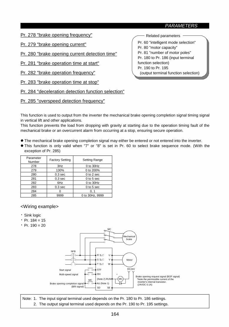
PARAMETERS
164
Pr. 60 "intelligent mode selection"Pr. 80 "motor capacity"Pr. 81 "number of motor poles"Pr. 180 to Pr. 186 (input terminalfunction selection)Pr. 190 to Pr. 195 (output terminal function selection)
Related parametersz Brake sequence function (Pr. 278 to Pr. 285)
Pr. 278 "brake opening frequency"
Pr. 279 "brake opening current"
Pr. 280 "brake opening current detection time"
Pr. 281 "brake operation time at start"
Pr. 282 "brake operation frequency"
Pr. 283 "brake operation time at stop"
Pr. 284 "deceleration detection function selection"
Pr. 285 "overspeed detection frequency"
This function is used to output from the inverter the mechanical brake opening completion signal timing signalin vertical lift and other applications.This function prevents the load from dropping with gravity at starting due to the operation timing fault of themechanical brake or an overcurrent alarm from occurring at a stop, ensuring secure operation.
z The mechanical brake opening completion signal may either be entered or not entered into the inverter.z This function is only valid when "7" or "8" is set in Pr. 60 to select brake sequence mode. (With the
exception of Pr. 285)
ParameterNumber
Factory Setting Setting Range
278 3Hz 0 to 30Hz279 130% 0 to 200%280 0.3 sec 0 to 2 sec281 0.3 sec 0 to 5 sec282 6Hz 0 to 30Hz283 0.3 sec 0 to 5 sec284 0 0, 1285 9999 0 to 30Hz, 9999
<Wiring example>
· Sink logic· Pr. 184 = 15· Pr. 190 = 20
R ⟨L1⟩ U
S ⟨L2⟩ V
T ⟨L3⟩ W
MC
STF
RH
SD SE
MC MC
DC24V
*
NFB
Brake opening request signal (BOF signal) *Note the permissible current of the inverter's internal transistor. (24VDC 0.1A)
Start signal
Multi-speed signal
Brake opening completion signal
(Note 2) RUN
AU (Note 1)
Mechanical brake
Motor
(BRI signal)
Note: 1. The input signal terminal used depends on the Pr. 180 to Pr. 186 settings.2. The output signal terminal used depends on the Pr. 190 to Pr. 195 settings.
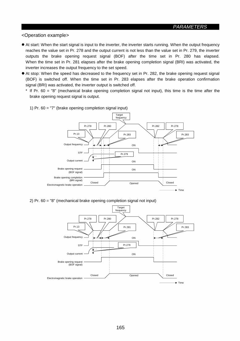
PARAMETERS
165
<Operation example>
z At start: When the start signal is input to the inverter, the inverter starts running. When the output frequencyreaches the value set in Pr. 278 and the output current is not less than the value set in Pr. 279, the inverteroutputs the brake opening request signal (BOF) after the time set in Pr. 280 has elapsed.When the time set in Pr. 281 elapses after the brake opening completion signal (BRI) was activated, theinverter increases the output frequency to the set speed.
z At stop: When the speed has decreased to the frequency set in Pr. 282, the brake opening request signal(BOF) is switched off. When the time set in Pr. 283 elapses after the brake operation confirmationsignal (BRI) was activated, the inverter output is switched off.* If Pr. 60 = "8" (mechanical brake opening completion signal not input), this time is the time after the
brake opening request signal is output.
1) Pr. 60 = "7" (brake opening completion signal input)
STF
ON
ON
Pr.280Pr.278
Pr.13 Pr.283
Pr.278Pr.282
Pr.283
ON
Pr.279
Time
Targetfrequency
Output frequency
Output current
Brake opening request(BOF signal)
Brake opening completion(BRI signal)
Electromagnetic brake operationClosed Opened Closed
2) Pr. 60 = "8" (mechanical brake opening completion signal not input)
STF
ON
ON
Pr.280Pr.278
Pr.13 Pr.281
Pr.278Pr.282
Pr.283
Pr.279
Time
Targetfrequency
Output frequency
Output current
Brake opening request(BOF signal)
Electromagnetic brake operationClosed Opened Closed

PARAMETERS
166
<Setting>
(1) Parameter setting
1) Select advanced magnetic flux vector control. (Pr. 80, Pr. 81 •"9999")2) Set "7 or 8" (brake sequence mode) in Pr. 60.
To ensure more complete sequence control, it is recommended to set "7" (brake opening completion signalinput) in Pr. 60. Note that the automatic restart after instantaneous power failure function is not activatedwhen the brake sequence mode is selected.
3) Refer to the following table and set the parameters:
ParameterNumber
Name Setting Description
278Brake openingfrequency
0 to 30HzSet to the rated slip frequency of the motor + about 1.0Hz.This parameter may only be set if Pr. 278 ≤ Pr. 282.
279 Brake opening current 0 to 200%Generally, set this parameter to about 50 to 90%. If the setting is toolow, the load is liable to drop with gravity at start.Suppose that the rated inverter current is 100%.
280Brake opening currentdetection time
0 to 2 sec Generally, set this parameter to about 0.1 to 0.3 seconds.
281Brake operation timeat start
0 to 5 secPr. 60 = 7: Set the mechanical delay time until the brake is loosened.Pr. 60 = 8: Set the mechanical delay time until the brake is loosened +about 0.1-0.2 seconds.
282Brake closingfrequency
0 to 30HzAt this frequency, the brake opening request signal (BOF) is switchedoff. Generally, set this parameter to the Pr. 278 setting + 3-4Hz.This parameter may only be set if Pr. 282 ≥ Pr. 278.
283Brake operation timeat stop
0 to 5 sec
Pr. 60 = 7: Set the mechanical delay time until the brake is closed + 0.1seconds.Pr. 60 = 8: Set the mechanical delay time until the brake is closed +about 0.2 to 0.3 seconds.
0 Deceleration is not detected.
284Decelerationdetection functionselection 1
If deceleration is not normal during deceleration operation, theinverter alarm (E.MB2) is provided to shut off the output and switch offthe brake opening request signal (BOF).
0 to 30HzIf (detected frequency) - (output frequency) > Pr. 285 in the PLGfeedback control mode, the inverter alarm (E.MB1) is provided to shut offthe output and switch off the brake opening request signal (BOF).
285Overspeed detectionfrequency
9999 Overspeed is not detected.
Note: When using this function, set the acceleration time to 1 second or longer.
(2) Explanations of terminals used
The terminals must be allocated using Pr. 180 to Pr. 186 and Pr. 190 to Pr. 195.
Brake Sequence ModeSignal Terminals Used Pr. 60 = 7 (with mechanical brake
opening completion signal)Pr. 60 = 8 (without mechanical
brake opening completion signal)BOF According to Pr. 180 to Pr. 186 Brake opening request Brake opening requestBRI According to Pr. 190 to Pr. 195 Brake opening completion signal
Note: 1. The brake opening completion signal (BRI) is a parameter valid when Pr. 60 = 7.2. When the terminal functions are changed using Pr. 180 to 186 and Pr. 190 to Pr. 195, the other
functions may be affected. Confirm the functions of the corresponding terminals before makingsettings.

PARAMETERS
167
(3) Protective functions
If any of the following errors occur in the brake sequence mode, the inverter results in an alarm, shuts off theoutput and switches off the brake opening request signal (BOF terminal).On the operation panel (FR-DU04) LED and parameter unit (FR-PU04) screen, the following errors aredisplayed:
ErrorDisplay
Error Display
E.MB1 (Detected frequency) - (output frequency) > Pr. 286 in the PLG feedback control mode. (Overspeed detection function)
E.MB2Deceleration is not normal during deceleration operation (Use Pr. 284 to select this function.) (Except stall preventionoperation)
E.MB3 Brake opening request signal (BOF) switched on though the motor is at a stop. (Gravity drop prevention function)
E.MB4More than 2 seconds after the run command (forward or reverse rotation) is input, the brake opening request signal(BOF) does not switch on.
E.MB5More than 2 seconds after the brake opening request signal switched on, the brake opening completion signal (BRI)does not switch on.
E.MB6Though the inverter had switched on the brake opening request signal (BOF), the brake opening completion signal (BRI)switched off during that period.
E.MB7More than 2 seconds after the brake opening request signal (BOF) switched off at a stop, the brake opening completionsignal (BRI) does not switch off.
Note: During PLG feedback control (when the FR-A5AP option is loaded), overspeed detection (Pr. 285) isvalid if the Pr. 60 setting is other than "7 or 8".

PARAMETERS
168
z Droop control (Pr. 286, Pr. 287)
Pr. 286 "Droop gain"
Pr. 287 "Droop filter time constant"
This function balances the load in proportion to the load torque with or without PLG, and provides speeddrooping characteristics.This is effective in balancing the load when using multiple inverters.z The output frequency is varied according to the amount of torque current during unbalanced flux vector
control and vector control.The drooping amount at the rated torque is set by the droop gain as a percentage using the ratedfrequency as a reference.
Droop compensation frequency = Amount of torque current after filtering
Rated current × Rated frequency × droop gain
100
z Confirm the following items when using the droop control.1. This function is valid when Pr. 286 ≠ "0" during unbalanced flux vector and vector control.2. This function is valid when the operation state is constant speed operation.3. The upper limit of the droop compensation frequency is 120Hz.4. The rated current follows the value set in Pr. 9 "Motor rated current".
Parameter No. Name Setting range Min. setting unit Factory setting286 Droop gain 0 to 100% 0.01% 0%287 Droop filter time constant 0.00 to 1.00s 0.01s 0.3s
Droop gain
Torque100%
Droop compensation frequency
Fre
quen
cy
<Setting>Refer to the following table and set each parameter.
Parameter No. Details
286Set the drooping amount at the rated torque as a percentage with respect to the ratedfrequency.When the setting value is "0", the function will be invalid (no droop control).
287 Set the time constant of the filter applied on the torque amount current.

PARAMETERS
169
Pr. 54 "FM terminal function selection"Pr. 55 "frequency monitoring reference"Pr. 56 "current monitoring reference"Pr. 158 "AM terminal function selection"
Related parametersz Meter (frequency meter) calibration (Pr. 900, Pr. 901)
Pr. 900 "FM terminal calibration"
Pr. 901 "AM terminal calibration"
z By using the operation panel/parameter unit, you can calibrate a meter connected to terminal FM to fullscale.
z Terminal FM provides the pulse output. By setting Pr. 900, you can calibrate the meter connected to theinverter from the parameter unit without providing a calibration resistor.
z You can display a digital value on a digital counter using the pulse train signal from terminal FM. A 1440Hzoutput is provided at the full scale value as explained in the section of Pr. 54. When the running frequencyhas been selected for monitoring, the ratio of this FM terminal output frequency can be set in Pr. 55.
(–) (+)
1mA
DC8V
T2
T1
FM (AM)
SD (5)
(–) (+) 1440HzFM (AM)
SD (5)
Note: The parameter is factory-set to 1mA full-scale or 1440Hz FM output frequency at 60Hz.
Meter1mA full scaleAnalog meter
Pulse width T1 Pulse period T2
(Digital meter)
:Adjusted with Pr. 900:Set in Pr. 55 (valid for frequency monitoring only)
z Terminal AM is factory-set to provide a 10VDC output in the full-scale state of each monitored data. Pr. 901allows the output voltage ratio (gain) to be adjusted according to the meter reading. Note that the maximumoutput voltage is 10VDC.
(1)Calibration of terminal FM1) Connect a meter (frequency meter) across inverter terminals FM-SD. (Note the polarity. FM is the
positive terminal.)2) When a calibration resistor has already been connected, adjust the resistance to "0" or remove the
resistor.3) Set any of "1 to 3, 5 to 14, 17, 18 and 21" in Pr. 54.
When the running frequency or inverter output current has been selected as the output signal, preset inPr. 55 or Pr. 56 the running frequency or current at which the output signal is 1440Hz.At this 1440Hz, the meter normally deflects to full scale.
(2)Calibration of terminal AM1) Connect a 0-10VDC meter (frequency meter) across inverter terminals AM-5. (Note the polarity. AM is
the positive terminal.)2) Set any of "1 to 3, 5 to 14, 17, 18 and 21" in Pr. 158.
When the running frequency or inverter output current has been selected as the output signal, preset inPr. 55 or Pr. 56 the running frequency or current at which the output signal is 10V.
3) When outputting a signal which cannot achieve a 100% value easily by operation, e.g. output current,set "21" in Pr. 158 and perform the following operation. After that, set "2" (output current, for example)in Pr. 158.

PARAMETERS
170
<Operation procedure>
· When operation panel (FR-DU04) is used
8) Press the [STOP/RESET] key to stop the inverter.
1) Select the PU operation mode.
2) Set the running frequency.
3) Press the [SET] key.
4) Read Pr. 900 "FM terminal calibration" or Pr. 901 "AM terminal calibration".
5) Press the [FWD] key to run the inverter. (Motor need not be connected.)
7) Press the [SET] key for about 1.5 seconds.
6) Hold down the [UP/DOWN] key to adjust the meter pointer to the required position.
(Depending on the setting, the pointer may take some time to move.)
Note: 1. Pr. 900 is factory-set to 1mA full-scale or 1440Hz FM output frequency at 60Hz. The maximumpulse train output of terminal FM is 2400Hz.
2. When a frequency meter is connected across terminals FM-SD to monitor the running frequency,the FM terminal output is filled to capacity at the factory setting if the maximum output frequencyreaches or exceeds 100Hz. In this case, the Pr. 55 setting must be changed to the maximumfrequency.
3. For the operation procedure using the parameter unit (FR-PU04), refer to the FR-PU04instruction manual.

PARAMETERS
171
Pr. 20 "acceleration/decelerationreference frequency"
Pr. 73 "0-5V/0-10V selection"
Related parametersz Frequency setting voltage (current) bias and gain (Pr. 902 to Pr. 905)
Pr. 902 "frequency setting voltage bias"
Pr. 903 "frequency setting voltage gain"
Pr. 904 "frequency setting current bias"
Pr. 905 "frequency setting current gain"
You can set the output frequency as desired in relation to the frequency setting signal (0 to 5V, 0 to 10V or 4to 20mA DC).
The "bias" and "gain" functions are used to adjust the relationship between the input signal entered fromoutside the inverter to set the output frequency, e.g. 0 to 5VDC, 0 to 10VDC or 4 to 20mADC, and the outputfrequency.
z Use Pr. 902 to set the bias frequency at 0V.z Use Pr. 903 to set the output frequency relative to the frequency command voltage set in Pr. 73.z Use Pr. 904 to set the bias frequency at 4mA.z Use Pr. 905 to set the output frequency relative to the 20mA frequency command current (4 to 20mA).
ParameterNumber
Factory Setting Setting Range
902 0V 0Hz 0 to 10V 0 to 60Hz903 5V 60Hz ⟨50Hz⟩ 0 to 10V 1 to 400Hz904 4mA 0Hz 0 to 20mA 0 to 60Hz905 20mA 60Hz ⟨50Hz⟩ 0 to 20mA 1 to 400Hz
60Hz⟨50Hz⟩
Pr.902
Pr.904
Pr.903
Pr.73
Pr.905
Gain
Out
put f
requ
ency
(H
z)
Bias
Factory setting
Frequency setting signal0
0
4
0
5V
10V
20mA
100%
<Setting>
(1) The frequency setting voltage biases and gains may be adjusted in either of the following three ways:1) Any point can be adjusted with a voltage applied across terminals 2-5.2) Any point can be adjusted with no voltage applied across terminals 2-5.3) Bias voltage is not adjusted.
(2) The frequency setting current biases and gains may be adjusted in either of the following three ways:1) Any point can be adjusted with a current flowing at terminal 4.2) Any point can be adjusted with no current flowing at terminal 4.3) Bias current is not adjusted.

PARAMETERS
172
<Adjustment procedure> Pr. 902 (Pr. 904) "frequency setting voltage (current) bias"
• When operation panel (FR-DU04) is used
Select the PU operation mode.
Read Pr. 902 (Pr. 904) value.
Press the [SET] key.
Using the [UP/DOWN] key, set the bias frequency.
Press the [SET] key for about 1.5 seconds
The bias voltage (current) setting flickers.
Press the [SET] key.The cursor moves to the next parameter.
Bias setting complete.
(1) Any point is adjusted with a voltage (current) applied
(2) Any point is adjusted with no voltage (current) applied
(3) Bias voltage (current) is not adjusted.
Apply the bias voltage (current).
Press the [SET] key for about 1.5 seconds.
The analog voltage (current) monitor valueacross terminals 2(4)-5 is displayed.
Using the [UP/DOWN] key, setthe bias voltage (current) in %.[0% for 0V (0mA), 100% for 5V(10V, 20mA)]
When the [UP] or [DOWN] keyis pressed, the present setting isdisplayed.
*Pr. 903 to Pr. 905 can also be adjusted similarly using the above procedure.
Note: 1. If the Pr. 903 or Pr. 905 (gain adjustment) value is changed, the Pr. 20 value does not change.The input signal to terminal 1 (frequency setting auxiliary input) is added to the frequency settingsignal.
2. For the operation procedure using the parameter unit (FR-PU04), refer to the FR-PU04 instructionmanual.

PARAMETERS
173
CAUTION
Be careful when setting any value other than "0". Even without the speed command, themotor will start running at the set frequency by merely switching on the start signal.
z Buzzer control (Pr. 990)
Pr. 990 "buzzer control"
You can make the buzzer "beep" when you press any key of the operation panel or parameter unit.
ParameterNumber
Factory Setting Setting Range Remarks
990 1 0, 1 0: Without beep, 1: With beep

5
CHAPTER 5
PROTECTIVE FUNCTIONS
This chapter explains the "protective functions" of thisproduct.Always read the instructions before using the equipment.
5.1 Errors (Alarms) ........................................................174 5.2 Troubleshooting .......................................................179 5.3 Precautions for Maintenance and Inspection ...........182
CHAPTER 1 OUTLINE
CHAPTER 2 INSTALLATION AND WIRING
CHAPTER 3 OPERATION
CHAPTER 4 PARAMETERS
CHAPTER 5 PROTECTIVE FUNCTIONS
CHAPTER 6 SPECIFICATIONS
CHAPTER 7 OPTIONS
APPENDICES

5.1 Errors (Alarms)PROTECTIVE FUNCTIONS
174
5 PROTECTIVE FUNCTIONS5.1 Errors (alarms)
If any fault has occurred in the inverter, the corresponding protective function is activated and the error(alarm) indication appears automatically on the PU display. When the protective function is activated, refer to"5.2 Troubleshooting" and clear up the cause by taking proper action. If an alarm stop has occurred, theinverter must be reset to restart it.
5.1.1 Error (alarm) definitions
OperationPanel
Display(FR-DU04)
ParameterUnit
(FR-PU04)Name Description
E.OC1OC DuringAcc
Duringacceleration
E.OC2Stedy SpdOC
Duringconstantspeed
E.OC3OC DuringDec
DuringdecelerationDuring stop
Overcurrentshut-off
When the inverter output current reaches or exceeds approximately200% of the rated current, the protective circuit is activated to stop theinverter output.
E.OV1OV DuringAcc
Duringacceleration
E.OV2Stedy SpdOV
Duringconstantspeed
E.OV3OV DuringDec
DuringdecelerationDuring stop
Regenerativeovervoltageshut-off
If regenerative energy from the running motor causes the inverter'sinternal main circuit DC voltage to reach or exceed the specified value,the protective circuit is activated to stop the inverter output.This may also be activated by a surge voltage generated in the powersupply system.
E.THMMotorOvrload
Motor
The electronic overcurrent protection in the inverter detects motoroverheat due to overload or cooling capability reduced during constant-speed operation. When 85% of the preset value is reached, pre-alarm(TH indication) occurs. When the specified value is reached, theprotective circuit is activated to stop the inverter output. When a specialmotor such as a multi-pole motor or more than one motor is run, themotor cannot be protected by the electronic overcurrent protection.Provide a thermal relay in the inverter output circuit.
E.THTInv.Overload
Overloadshut-off(electronicovercurrentprotection)
Inverter
If a current more than 150% of the rated output current flows andovercurrent shut-off (OC) does not occur (200% or less), inverse-timecharacteristics cause the electronic overcurrent protection to be activatedto stop the inverter output. (Overload immunity: 150%, 60 seconds)
E.IPFInst.Pwr.Loss
Instantaneous power failureprotection
If a power failure has occurred in excess of 15ms (this applies also toinverter input shut-off), this function is activated to stop the inverteroutput to prevent the control circuit from misoperation. At this time, thealarm output contacts are opened (across B-C) and closed (across A-C)(Note 1). If a power failure persists for more than 100ms, the alarmoutput is not provided, if the start signal is on at the time of powerrestoration, the inverter will restart. (If a power failure is instantaneouswithin 15ms, the control circuit operates properly.)
E.UVTUnderVoltage
Undervoltage protection
•If the inverter power supply voltage reduces, the control circuit will notoperate properly, resulting in decreased motor torque or increasedheat generation. To prevent this, if the power supply voltage reducesbelow 150V (about 300V for the 400V class), this function stops theinverter output.
•When a jumper is not connected across P-P1 ⟨+ -P1⟩, the undervoltageprotective function is activated.
E.FINH/SinkO/Temp
Fin overheatIf the cooling fin overheats, the temperature sensor is activated to stopthe inverter output.
FNFanFailure
Fan fault
For the inverter which contains a cooling fan, FN is displayed on theoperation panel and the fan fault signal (FAN) and light fault signal (LF)are output when the cooling fan stops due to a fault or operatesdifferently from the setting of Pr. 244 "cooling fan operation selection".
E. BEBr.Cct.Fault
Brake transistor alarmdetection
If the brake circuit fault has occurred due to damaged brake transistors,etc., this function stops the inverter output.In this case, the inverter power must be switched off immediately.

PROTECTIVE FUNCTIONS
175
OperationPanel
Display(FR-DU04)
ParameterUnit
(FR-PU04)Name Description
E. GFGroundFault
Output side ground faultovercurrent protection
This function stops the inverter output if a ground fault current flows dueto a ground fault occurring in the inverter's output (load) side whenstarting the inverter. A ground fault occurring at low ground resistancemay activate the overcurrent protection (OC1 to OC3).
E.OHT OH FaultExternal thermal relayoperation (Note 3)
If the external thermal relay designed for motor overheat protection or theinternally mounted temperature relay in the motor switches on (relaycontacts "open"), the inverter output can be stopped if those contactshad been entered into the inverter. If the relay contacts are resetautomatically, the inverter will not restart unless it is reset.
During acceleration
If a current more than 150% (Note 4) of the rated inverter current flows inthe motor, this function lowers the frequency until the load currentreduces to prevent the inverter from resulting in overcurrent shut-off.When the load current has reduced below 150%, this function increasesthe frequency again to accelerate and operate the inverter up to the setfrequency.
During constant-speedoperation
If a current more than 150% (Note 4) of the rated inverter current flows inthe motor, this function lowers the frequency until the load current reducesto prevent overcurrent shut-off. When the load current has reduced below150%, this function increases the frequency up to the set value.
E.OLT(Whenstallpreventionoperationhasreducedtherunningfrequencyto 0. OLduring stallpreventionoperation)
Stll PrevSTP(OL shownduring stallpreventionoperation)
During deceleration
If the regenerative energy of the motor has increased above the brakecapability, this function increases the frequency to prevent overvoltageshut-off. If a current more than 150% (Note 4) of the rated invertercurrent flows in the motor, this function increases the frequency until theload current reduces to prevent the inverter from resulting in overcurrentshut-off. When the load current has reduced below 150%, this functiondecreases the frequency again.
E.OPTOptionFault
Option alarm
•Stops the inverter output if the dedicated inboard option used in theinverter results in setting error or connection (connector) fault.
• When the high power factor converter connection is selected, this alarmis displayed if AC power is connected to R, S, T ⟨L1, L2, L3⟩.
E.OP1 toOP3
Option slotalarm1 to 3
Option slot alarmStops the inverter output if a functional fault (such as communicationerror of the communication option) occurs in the inboard option loaded inany slot.
E. PECorruptMemry
Parameter errorStops the output if a fault occurs in the E2PROM which stores parametersettings.
E.PUEPU LeaveOut
PU disconnectionoccurrence
This function stops the inverter output if communication between inverterand PU is suspended, e.g. the operation panel or parameter unit isdisconnected, when "2", "3", "16" or "17" is set in Pr. 75 "resetselection/PU disconnection detection/PU stop selection". This functionstops the inverter output if the number of successive communicationerrors is greater than the number of permissible retries when Pr. 121value is "9999" for RS-485 communication from PU connector.This function stops the inverter output if communication is broken for aperiod of time set in Pr. 122.
E.RETRetry NoOver
Retry count exceededIf operation cannot be resumed within the number of retries set, thisfunction stops the inverter output.
E.LF Open output phaseprotection
This function stops the inverter output when any of the three phases (U,V, W) on the inverter's output side (load side) opens.
E.CPU CPU Fault CPU errorIf the arithmetic operation of the built-in CPU does not end within apredetermined period, the inverter self-determines it has an alarm andstops the output.
E.E6 CPU error CPU errorIf the arithmetic operation of the peripheral circuit of the built-in CPUdoes not end within a predetermined period, the inverter self-determinesit as an alarm and stops the output.
E.E7 CPU error CPU errorThe inverter output is stopped if a data error occurs in the peripheralcircuit of the built-in CPU.
E.P24 24VDC power output shortcircuit
When 24VDC power output from the PC terminal is shorted, this functionshuts off the power output. At this time, all external contact inputs switchoff. The inverter cannot be reset by entering the RES signal. To reset,use the operation panel or switch power off, then on again.
E.CTE Operation panel power shortcircuit
When the operation panel power (P5S of the PU connector) is shorted,this function shuts off the power output. At this time, the operation panel(parameter unit) cannot be used and RS-485 communication from thePU connector cannot be made. To reset, enter the RES signal or switchpower off, then on again.

PROTECTIVE FUNCTIONS
176
OperationPanel
Display(FR-DU04)
ParameterUnit
(FR-PU04)Name Description
Brake resistor overheatprotection
Inverters of 7.5K or less contain a brake resistor. When the regenerativebrake duty from the motor has reached 85% of the specified value,pre-alarm (RB indication) occurs. If the specified value is exceeded, thebrake circuit operation is stopped temporarily to protect the brake resistorfrom overheating. (If the brake is operated in this state, regenerativeovervoltage shut-off will occur.) When the brake resistor has cooled, thebrake operation is resumed.
E.MB1 toMB7
Brake sequence errorThis function stops the inverter output if a sequence error occurs duringthe use of the brake sequence function (Pr. 278 to Pr. 285).
Err Error The inverter output is stopped if a malfunction occurs in the built-in CPU.
Note: 1. If Pr. 195 (A, B, C terminal function selection) is as set in the factory.2. The terminals used must be allocated using Pr. 190 to Pr. 195.3. External thermal relay operation is only activated when "OH" is set in any of Pr. 180 to Pr. 186
(input terminal function selection).4. Indicates that the stall prevention operation level has been set to 150% (factory setting). If this
value is changed, stall prevention is operated at the new value.5. Resetting method
When the protective function is activated and the inverter stops its output (the motor is coasted toa stop), the inverter is kept stopped. Unless reset, the inverter cannot restart. To reset theinverter, use any of the following methods: switch power off once, then on again; short resetterminal RES-SD for more than 0.1 second, then open; press the [RESET] key of the parameterunit (use the help function of the parameter unit). If RES-SD is kept shorted, the operation panelwill show "Err." or the parameter unit will show that the inverter is being reset.

PROTECTIVE FUNCTIONS
177
z To know the operating status at the occurrence of an alarm
When any alarm has occurred, the display automatically switches to the indication of the correspondingprotective function (error). By pressing the [MODE] key at this point without resetting the inverter, the displayshows the output frequency. In this way, it is possible to know the running frequency at the occurrence of thealarm. It is also possible to know the current in the same manner. However, these values are not stored inmemory and are erased when the inverter is reset.
5.1.2 Correspondences between digital and actual characters
There are the following correspondences between the actual alphanumeric characters and the digitalcharacters displayed on the operation panel:
Actual Digital Actual Digital Actual Digital
0
1
2
3
4
5
6
7
8
9
A
B
C
E
F
G
H
I
J
L
M
N
O
P
T
U
V
r
-
o
S

PROTECTIVE FUNCTIONS
178
5.1.3 Alarm code output
By setting Pr. 76 "alarm code output selection", an alarm definition can be output as a 4-bit digital signal. Thissignal is output from the open collector output terminals equipped as standard on the inverter.Correlations between alarm definitions and alarm codes are as follows.
Output Terminal Signal On-OffOperation PanelDisplay
(FR-DU04)SU IPF OL FU
Alarm Code Alarm Output (across B-C)
E.OC1 0 0 0 1 1E.OC2 0 0 1 0 2E.OC3 0 0 1 1 3
Provided (Open)
E.OV1E.OV2E.OV3
0 1 0 0 4 Provided (Open)
E.THM 0 1 0 1 5E.THT 0 1 1 0 6
Provided (Open)
E.IPF 0 1 1 1 7 Provided (Open)E.UVT 1 0 0 0 8 Provided (Open)E.FIN 1 0 0 1 9 Provided (Open)E. BE 1 0 1 0 A Provided (Open)E. GF 1 0 1 1 B Provided (Open)E.OHT 1 1 0 0 C Provided (Open)
E.OLT 1 1 0 1 DNot provided (Provided when OLTis displayed) (Open)
E.OPT 1 1 1 0 E Provided (Open)E.OP1 to E.OP3 1 1 1 0 E Provided (Open)
E. PE Provided (Open)E.PUE Provided (Open)E.RET Provided (Open)E.LF Provided (Open)
E.CPU Provided (Open)E.E6 Provided (Open)E.E7
1 1 1 1 F
Provided (Open)
(Note) 0: Output transistor OFF, 1: Output transistor ON (common terminal SE)The alarm output assumes that Pr. 195 setting is "99" (factory setting).
5.1.4 Resetting the inverter
The inverter can be reset by performing any of the following operations. Note that the electronic overcurrentprotection's internal heat calculation value and the number of retries are cleared (erased) by resetting theinverter.
Operation 1: Using the operation panel (FR-DU04), press the [RESET] key to reset the inverter.Operation 2: Switch power off once, then switch it on again.Operation 3: Switch on the reset signal (RES).

5.2 TroubleshootingPROTECTIVE FUNCTIONS
179
5.2 Troubleshooting
If any function of the inverter is lost due to occurrence of a fault, clear up the cause and make correction inaccordance with the following procedures. Contact your sales representative if the corresponding fault is notfound below, the inverter has failed, parts have been damaged, or any other fault has occurred.
5.2.1 Checking the operation panel display at alarm stop
The alarm code is displayed on the operation panel to indicate the cause of a faulty operation. Clear up thecause and take proper action in accordance with the following table:
Fault RankOperation PanelDisplay Check Point Remedy
Major Minor
E.OC1 Acceleration too fast?Check for output short circuit or ground fault. Increase acceleration time.
E.OC2 Sudden load change?Check for output short circuit or ground fault. Keep load stable.
E.OC3Deceleration too fast?Check for output short circuit or ground fault.Mechanical brake of motor operating too fast?
Increase deceleration time.Check brake operation.
E.OV1 Acceleration too fast? Increase acceleration time.
E.OV2 Sudden load change? Keep load stable.
E.OV3 Deceleration too fast?
Increase deceleration time. (Setdeceleration time which matches loadGD2.)Reduce braking duty.
E.THME.THT
Motor used under overload? Reduce load.Increase motor and inverter capacities.
E.IPF Check the cause of instantaneous powerfailure. Restore power.
E.UVTLarge-capacity motor started?Jumper or DC reactor connected acrossterminals P-P1 (+ -P1)?
Check power system equipment such aspower supply.Connect jumper or DC reactor acrossterminals P-P1 (+ -P1).
E.FIN Ambient temperature too high? Set ambient temperature withinspecifications.
E. BE Correct brake duty? Change inverter.
E. GF Check motor and cables for ground fault. Resolve ground faults.
E.OHT Check motor for overheat. Reduce load and frequency of operation.
E.OLT Motor used under overload? Reduce load.Increase motor and inverter capacities.
E.OPT Check for loose connectors. Connect securely
E.OP1 to E.OP3 Option function setting or operation proper?(1 to 3 indicates the option slot numbers.) Check the option function setting, etc.
E. PE Number of parameter write times too many? Change inverter.
E.PUE DU or PU fitted securely? Fit DU or PU securely.
E.RET Check the cause of retry failure. Correct retry problem.
E.LF Check for open output phase. Repair open phase.
E.CPU Check for loose connectors. Change inverter.Connect securely.
E.E6 Check for loose connectors. Change inverter.Connect securely.
E.E7 Check for loose connectors. Change inverter.Connect securely.
Err Check for loose connectors. Change inverter.Connect securely.
E.P24 Check PC terminal output for short. Repair short.
E.CTE Check PU connector cable for short. Check PU and cable.
FN Cooling fan normal? Change fan.
E.MB1 to MB7 Check brake sequence. Change brake sequence.
PS STOP key of operation panel pressed duringexternal operation to stop?
Check load status.For clearing method, refer to page 96.
RB Brake resistor used too often? Increase deceleration time.
TH Load too large? Sudden acceleration? Reduce load amount or frequency ofrunning.
OL
Motor used under overload?Sudden deceleration?oL: Overvoltage stallOL: Overcurrent stall
Lighten load.Reduce frequency of braking.
z When the protective function is activated, take proper corrective action, reset the inverter, then resumeoperation.

PROTECTIVE FUNCTIONS
180
5.2.2 Faults and check points
POINT: Check the corresponding areas. If the cause is still unknown, it is recommended to initialize theparameters (return to factory settings), re-set the required parameter values, and check again.
(1) Motor remains stopped.
1) Check the main circuit· Check that a proper power supply voltage is applied (operation panel display is provided).· Check that the motor is connected properly.
2) Check the input signals· Check that the start signal is input.· Check that both the forward and reverse rotation start signals are not input.· Check that the frequency setting signal is not zero.· Check that the AU signal is on when the frequency setting signal is 4 to 20mA.· Check that the output stop signal (MRS) or reset signal (RES) is not on.· Check that the CS signal is not off when automatic restart after instantaneous power failure is
selected (Pr. 57 = other than "9999").3) Check the parameter settings
· Check that the reverse rotation prevention (Pr. 78) is not selected.· Check that the operation mode (Pr. 79) setting is correct.· Check that the bias and gain (Pr. 902 to Pr. 905) settings are correct.· Check that the starting frequency (Pr. 13) setting is not greater than the running frequency.· Check that various operational functions (such as three-speed operation), especially the maximum
frequency (Pr. 1), are not zero.4) Check the load
· Check that the load is not too heavy.· Check that the shaft is not locked.
5) Others· Check that the ALARM lamp is not lit.· Check that the Pr. 15 "jog frequency" setting is not lower than the Pr. 13 "starting frequency" value.
(2) Motor rotates in opposite direction.
· Check that the phase sequence of output terminals U, V and W is correct.· Check that the start signals (forward rotation, reverse rotation) are connected properly.
(3) Speed greatly differs from the setting.
· Check that the frequency setting signal is correct. (Measure the input signal level.)· Check that the following parameter settings are proper: Pr. 1, Pr. 2, Pr. 902 to Pr. 905, Pr. 19.· Check that the input signal lines are not affected by external noise. (Use shielded cables)· Check that the load is not too heavy.
(4) Acceleration/deceleration is not smooth.
· Check that the acceleration and deceleration time settings are not too short.· Check that the load is not too heavy.· Check that the torque boost (Pr. 0, Pr. 46, Pr. 112) setting is not too large to activate the stall
function.

PROTECTIVE FUNCTIONS
181
(5) Motor current is large.
· Check that the load is not too heavy.· Check that the torque boost (Pr. 0, Pr. 46, Pr. 112) setting is not too large.
(6) Speed does not increase.
· Check that the maximum frequency (Pr. 1) setting is correct.· Check that the load is not too heavy. (In agitators, etc., load may become heavy in winter.)· Check that the torque boost (Pr. 0, Pr. 46, Pr. 112) setting is not too large to activate the stall
prevention function.
(7) Speed varies during operation.
During operation under advanced magnetic flux vector control, the output frequency varies with loadfluctuation between 0 and 2Hz. This is a normal operation and is not a fault.
1) Inspection of load· Check that the load is not varying.
2) Inspection of input signal· Check that the frequency setting signal is not varying.· Check that the frequency setting signal is not affected by induced noise.
3) Others· Check that the settings of the applied motor capacity (Pr. 80) and the number of applied motor poles
(Pr. 81) are correct for the inverter and motor capacities in advanced magnetic flux vector control.· Check that the wiring length is within 30m (98.42 feet) in advanced magnetic flux vector control.· Check that the wiring length is correct in V/F control.
(8) Operation mode is not changed properly.
If the operation mode is not changed properly, check the following:1. External input signal .............Check that the STF or STR signal is off.
When it is on, the operation mode cannot be changed.2. Parameter setting .................Check the Pr. 79 setting.
When the setting of Pr. 79 "operation mode selection" is "0" (factorysetting), switching input power on places the inverter in the externaloperation mode. Press the operation panel's [MODE] key three timesand press the [UP] key (press the [PU] key for the parameter unit(FR-PU04)). This changes the external operation mode into the PUoperation mode. For any other setting (1 to 8), the operation mode islimited according to the setting.
(9) Operation panel (FR-DU04) display is not provided.
· Make sure that the operation panel is connected securely with the inverter.
(10) POWER lamp is not lit.
· Make sure that the wiring and installation are correct.

5.3 Precautions for Maintenance and InspectionPROTECTIVE FUNCTIONS
182
5.3 Precautions for Maintenance and Inspection
The transistorized inverter is a static unit mainly consisting of semiconductor devices. Daily inspection mustbe performed to prevent any fault from occurring due to adverse influence by the operating environment, suchas temperature, humidity, dust, dirt and vibration, changes in the parts with time, service life, and otherfactors.
5.3.1 Precautions for maintenance and inspection
For some short time after the power is switched off, a high voltage remains in the smoothing capacitor. Whenaccessing the inverter for inspection, switch power off. When more than 10 minutes have elapsed, make surethat the voltage across the main circuit terminals P-N of the inverter is 30VDC or less using a tester, etc.
5.3.2 Check items
(1) Daily inspections
• Check the following:1) Motor operation fault2) Improper installation environment3) Cooling system fault4) Unusual vibration and noise5) Unusual overheating and discoloration
• During operation, check the inverter input voltages using a tester.
(2) Cleaning
Always run the inverter in a clean state.When cleaning the inverter, gently wipe dirty areas with a soft cloth immersed in neutral detergent or ethanol.Note: Do not use solvent, such as acetone, benzene, toluene and alcohol, as they will cause the inverter
surface paint to peel off.Do not use detergent or alcohol to clean the display and other sections of the operation panel (FR-DU04) or parameter unit (FR-PU04) as these sections do not like them.
5.3.3 Periodic inspection
Check the areas inaccessible during operation and requiring periodic inspection. For periodic inspection,consult us.1) Cooling system:.....................Clean the air filter, etc.2) Screws and bolts: ..................These parts may become loose due to vibration, temperature changes, etc.
Check that they are tightened securely and retighten as necessary.3) Conductors and insulating materials: Check for corrosion and damage.4) Insulation resistance: Measure.5) Cooling fan, smoothing capacitor, relay: Check and change if necessary.

PROTECTIVE FUNCTIONS
183
5.3.4 Insulation resistance test using megger
1) Before performing the insulation resistance test using a megger on the external circuit, disconnect thecables from all terminals of the inverter so that the test voltage is not applied to the inverter.
2) For the continuity test of the control circuit, use a meter (high resistance range) and do not use the meggeror buzzer.
3) For the inverter, conduct the insulation resistance test on the main circuit only as shown below and do notperform the test on the control circuit. (Use a 500VDC megger.)
R ⟨L1⟩S ⟨L2⟩T ⟨L3⟩
UVM
IMInverter
Motor
Powersupply
DC500Vmegger
Ground terminal
5.3.5 Pressure test
Do not conduct a pressure test. The inverter's main circuit uses semiconductors, which may be deteriorated ifa pressure test is made.
Daily and Periodic Inspection
IntervalPeriodic
Area ofInspec-
tion
InspectionItem
DescriptionDaily 1
year2
years
Method Criterion Instrument
Surroundingenvironment
Check ambienttemperature, humidity,dust, dirt, etc.
(Refer to page 7)
Ambienttemperature:(constant torque)−10ºC to +50ºC,non-freezing.(Variable torque)−10ºC to +40ºC,non-freezingAmbient humidity:90% or less,non-condensing.
Thermometer,hygrometer,recorder
Overall unitCheck for unusualvibration and noise.
Visual and auditorychecks.
No fault.
General
Powersupplyvoltage
Check that main circuitvoltage is normal.
Measure voltageacross inverterterminals R-S-T⟨L1-L2-L3⟩.
Within permissibleAC voltagefluctuation(Refer to page190)
Meter, digitalmultimeter
General
(1) Check with megger(across main circuitterminals andground terminal).
(2) Check for loosescrews and bolts.
(3) Check for overheat-ing of each part.
(4) Clean.
(1) Disconnect allcables frominverter andmeasure acrossterminals R, S, T,V, W ⟨L1, L2, L3,V, W⟩ and groundterminal withmegger.
(2) Re-tighten.(3) Visual check.
(1) 5M Ω or more.(2), (3) No fault.
500VDC classmegger
Conductors,cables
(1) Check conductorsfor distortion.
(2) Check cablesheaths forbreakage.
(1), (2) Visual check. (1), (2) No fault.
Maincircuit
Terminalblock
Check for damage. Visual check. No fault

PROTECTIVE FUNCTIONS
184
Daily and Periodic Inspection
IntervalPeriodic
Area ofInspec-
tion
InspectionItem
DescriptionDaily 1
year2
years
Method Crlterlon Instrument
Invertermodule,Convertermodule
Check resistanceacross terminals.
Disconnect cablesfrom inverter andmeasure acrossterminals R, S, T, P,N and U, V, W, P, N⟨L1, L2, L3, +, − andU, V, W, +, −⟩ withtester range of 100Ω.
(See the followingpages)
Analog meter
Smoothingcapacitor
(1) Check for liquidleakage.
(2) Check for safetyvalve projection andbulge.
(3) Measureelectrostaticcapacity.
(1), (2) Visual check.(3) Measure with
capacity meter.
(1), (2) No fault.(3) 85% or moreof rated capacity.
Capacitymeter
Relay
(1) Check for chatterduring operation.
(2) Check for roughsurface oncontacts.
(1) Auditory check.(2) Visual check.
(1) No fault.(2) No fault.
Maincircuit
Resistor
(1) Check for crack inresistor insulation.
(2) Check for opencable.
(1) Visual check.Cement resistor,wire-woundresistor.
(2) Disconnect oneend and measurewith tester.
(1) No fault.(2) Error should
be within±10% ofindicatedresistancevalue.
Meter, digitalmultimeter
ControlcircuitProtec-tive circuit
Operationcheck
(1) Check balance ofoutput voltagesacross phases withinverter operatedindependently.
(2) Perform sequenceprotective operationtest to make sure ofno fault in protectiveand display circuits.
(1) Measure voltageacross inverteroutput terminalsU-V-W.
(2) Simulativelyconnect ordisconnectinverter protectivecircuit outputterminals.
(1) Phase-to-phase voltagebalance within4V (8V) for200V (400V).
(2) Fault mustoccur becauseof sequence.
Digitalmultimeter,rectifier typevoltmeter
Coolingsystem
Cooling fan
(1) Check for unusualvibration and noise.
(2) Check for looseconnection.
(1) Turn by hand withpower off.
(2) Re-tighten
No unusualvibration, unusualnoise.
Display(1) Check if LED lamp
is blown.(2) Clean.
(1) Light indicatorlamps on panel.
(2) Clean with rag.
(1) Check thatlamps are lit.
Display
Meter
Check that reading isnormal.
Check reading ofmeters on panel.
Must satisfyspecified andmanagementvalues.
Voltmeter,ammeter, etc.
General
(1) Check for unusualvibration and noise.
(2) Check for unusualodor.
(1) Auditory, sensory,visual checks.
(2) Check for unusualodor due tooverheating,damage, etc.
(1), (2) No fault.
Motor
Insulationresistance
(1) Check with megger(across terminalsand groundterminal).
(1) Disconnect cablesfrom U, V, W,including motorcables.
(1) 5M Ω or more
500V megger
Note: The value for the 400V class is indicated in the parentheses.

PROTECTIVE FUNCTIONS
185
z Checking the inverter and converter modules
<Preparation>(1) Disconnect the external power supply cables (R, S, T) ⟨L1, L2, L3⟩ and motor cables (U, V, W).(2) Prepare a meter. (Use 100Ω range.)
<Checking method>Change the polarity of the tester alternately at the inverter terminals R, S, T, U, V, W, P and N ⟨L1, L2, L3, U,V, W, + and −⟩, and check for continuity.
Note: 1. Before measurement, check that the smoothing capacitor is discharged.2. At the time of continuity, the measured value is several to several ten’s-of ohms depending on the
module type, circuit tester type, etc. If all measured values are almost the same, the modules arewithout fault.
<Module device numbers and terminals to be checked>
Tester Polarity Tester PolarityMeasured Value Measured Value
R ⟨L1⟩ P ⟨+⟩ Discontinuity R ⟨L1⟩ N ⟨−⟩ ContinuityD1
P ⟨+⟩ R ⟨L1⟩ ContinuityD4
N ⟨−⟩ R ⟨L1⟩ DiscontinuityS ⟨L2⟩ P ⟨+⟩ Discontinuity S ⟨L2⟩ N ⟨−⟩ Continuity
D2P ⟨+⟩ S ⟨L2⟩ Continuity
D5N ⟨−⟩ S ⟨L2⟩ Discontinuity
T ⟨L3⟩ P ⟨+⟩ Discontinuity T ⟨L3⟩ N ⟨−⟩ ContinuityCon
vert
erd
l
D3P ⟨+⟩ T ⟨L3⟩ Continuity
D6N ⟨−⟩ T ⟨L3⟩ Discontinuity
U P ⟨+⟩ Discontinuity U N ⟨−⟩ ContinuityTR1 P ⟨+⟩ U Continuity
TR4N ⟨−⟩ U Discontinuity
V P ⟨+⟩ Discontinuity V N ⟨−⟩ ContinuityTR2 P ⟨+⟩ V Continuity
TR6N ⟨−⟩ V Discontinuity
W P ⟨+⟩ Discontinuity W N ⟨−⟩ Continuity
Inve
rter
mod
ule
TR5 P ⟨+⟩ W Continuity
TR2N ⟨−⟩ W Discontinuity
D1 D2 D3
D4 D5 D6
TR1 TR3 TR5
TR4 TR6 TR2
U
V
W
R⟨L1⟩
S⟨L2⟩
T⟨L3⟩
C
P ⟨+⟩
N ⟨–⟩
Inverter moduleConverter module

PROTECTIVE FUNCTIONS
186
5.3.6 Replacement of parts
The inverter consists of many electronic parts such as semiconductor devices.The following parts may deteriorate with age because of their structures or physical characteristics, leading toreduced performance or failure of the inverter. For preventive maintenance, the parts must be changedperiodically.
(1) Cooling fan
The cooling fan cools heat-generating parts such as the main circuit semiconductor devices. The life of thecooling fan bearing is usually 10,000 to 35,000 hours. Hence, the cooling fan must be changed every 2 to 3years if the inverter is run continuously. When unusual noise and/or vibration is noticed during inspection, thecooling fan must be changed immediately.
z Removal
1) Push the catches from above and remove the fan cover.
2) Disconnect the fan connector(s).3) Remove the fan.
z Reinstallation
1) After confirming the orientation of the fan, reinstall the fan so that thearrow on the left of "AIR FLOW" faces up.
↑ AIR FLOW
<Fan side face>
2) Reconnect the fan connectors.When wiring, use care to avoid the cables being caught by the fan.
3) Reinstall the fan cover.
Fan cover
Fan
Fan connectors
<Example: FR-A520-5.5K>

PROTECTIVE FUNCTIONS
187
(2) Smoothing capacitors
A large-capacity aluminum electrolytic capacitor is used for smoothing the DC in the main circuit, and analuminum electrolytic capacitor is also used for stabilizing the control power in the control circuit. Theircharacteristics are adversely affected by ripple current, etc. When the inverter is operated in an ordinary, air-conditioned environment, change the capacitors about every 5 years. When 5 years have elapsed, thecapacitors will deteriorate more rapidly.Check the capacitors at least every year (less than six months if their life will be expired soon).Check the following:1) Case (side faces and bottom face for expansion)2) Sealing plate (for remarkable warping and extreme cracks)3) Explosion-proof valve (for excessive valve expansion and operation)4) Appearance, external cracks, discoloration, leakage. When the measured capacitance of the capacitor has
reduced below 85% of the rating, change the capacitor.
(3) Relays
To prevent a contact fault, etc., relays must be changed according to the number of accumulative switchingtimes (switching life).See the following table for the inverter parts replacement guide. Lamps and other short-life parts must also bechanged during periodic inspection.
Replacement Parts of the Inverter
Part Name Standard Replacement Interval Description
Cooling fan 2 to 3 years Change (as required)
Smoothing capacitor in main circuit 5 years Change (as required)
Smoothing capacitor on control board 5 years Change the board (as required)
Relays Change as required
5.3.7 Inverter replacement
The inverter can be changed with the control circuit wiring kept connected. Before replacement, remove thescrews in the wiring cover of the inverter.1) Remove the mounting screws in both ends of the control circuit terminal block.2) With both hands, pull down the terminal block from the back of the control circuit terminals.
3) When installing the terminal block to a new inverter, exercise care not to bend the pins of the control circuitterminal block connector.

PROTECTIVE FUNCTIONS
188
5.3.8 Measurement of main circuit voltages, currents and power
z Measurement of voltages and currents
Since the voltages and currents on the inverter power supply and output sides include harmonics,accurate measurement depends on the instruments used and circuits measured.When instruments for commercial frequency are used for measurement, measure the following circuitsusing the instruments given on the next page.
+ -
Ar
As
At
Vr
Vs
Vt
W11
W12
W13
Au
Av
Aw
Vu
Vv
Vw
W12
W22
V
R ⟨L1⟩
S ⟨L2⟩
T ⟨L3⟩
U
V
W
Inverter
P ⟨+⟩2
⟨–⟩ N
3-phasepowersupply
Instrumenttypes
Input voltage
Input current
Output voltage
Output current
To motor
5
Typical Measuring Points and Instruments
Note: Use an FFT to measure the output voltage accurately. Accurate measurement cannot be made if youuse a tester or general measuring instrument.

PROTECTIVE FUNCTIONS
189
Measuring Points and Instruments
Item Measuring Point Measuring InstrumentRemarks
(Reference Measured Value) *
Power supply voltage V1Across R-S, S-T and T-R⟨Across L1-L2, L2-L3 and L3-L1⟩ Moving-iron type AC voltmeter
Commercial power supplyWithin permissible AC voltagefluctuation
Power supply sidecurrent I1
R, S and T line currents⟨L1, L2 and L1 line currents⟩ Moving-iron type AC ammeter
Power supply side powerP1
At R, S and T, and across R-S,S-T and T-R⟨At L1, L2 and L3, and acrossL1-L2, L2-L3 and L3-L1⟩
Electrodynamic type single-phase wattmeter
P1 = W11 + W12 + W13
(3-wattmeter method)
Power supply side powerfactor Pf1
Calculate after measuring power supply voltage, power supply side current and power supply sidepower.
× 100%3 V1 × I1
P1Pf1 =
Output side voltage V2 Across U-V, V-Wand W-URectifier type AC voltmeter(Note 1) (Not moving-iron type)
Difference between phases iswithin ±1% of maximum outputvoltage.
Output side current I2 U, V and W line currentsMoving-iron type AC ammeter(Note 3)
Current should be equal to or lessthan rated inverter current.Difference between phases is 10%or lower.
Output side power P2At U, V and W, and across U-Vand V-W
Electrodynamic type single-phase wattmeter
P2 = W21 + W22
2-wattmeter method(or 3-wattmeter method)
Output side power factorPf2
Calculate in similar manner to power supply side power factor.
× 100%3 V2 × I2
P2Pf2 =
Converter output Across P-N ⟨Across + and −⟩ Moving-coil type (such astester)
POWER lamp lit1.35 × V1
Maximum 380V (760V) duringregenerative operation
Across 2 (+) −5 0 to 5V/0 to 10VDCAcross 1 (+) −5 0 to ±5V/0 to ±10VDCFrequency setting signalAcross 4 (+) −5 4 to 20mADCAcross 10 (+) −5 5VDCFrequency setting power
supply Across 10E (+) −5 10VDC
“5”
isco
mm
on.
Across FM (+) −SD
Approximately 5VDC atmaximum frequency(without frequency meter)
DC8V
T1
T2
Pulse width T1:Adjusted by Pr.900
Pulse cycle T2: Set by Pr.55(Valid for frequencymonitoring only)
Frequency meter signal
Across AM (+) −5Approximately 10DVC atmaximum frequency(without frequency meter)
Start signalSelect signal
Across STF, STR, RH, RM, RL,JOG, RT, AU, STOP, CS (+) −SD
Reset Across RES (+) −SDOutput stop Across MRS (+) −SD
Moving-coil type (Tester, etc.may be used) (Internalresistance: 50kΩ or larger)
20 to 30VDC when open.ON voltage: 1V or less
SD
is c
omm
on.
Alarm signalAcross A-CAcross B-C
Moving-coil type(such as tester)
Continuity check (Note 2)<At OFF> <At ON>
Across A-C: Discontinuity ContinuityAcross B-C: Continuity Discontinuity
Note 1. Accurate data will not be obtained by a tester.2. When Pr. 195 "A, B, C terminal function selection" setting is positive logic.3. When the carrier frequency exceeds 5kHz, do not use the instrument because overcurrent losses occurring in the metallic
parts inside the instrument will increase and may lead to burnout.In this case, use an approximate effective value type instrument.
* Values in parentheses indicate those for 400V class.

6
CHAPTER 6
SPECIFICATIONS
This chapter provides the "specifications" of this product.Always read the instructions before using the equipment.
6.1 Standard Specifications ...........................................190
CHAPTER 1 OUTLINE
CHAPTER 2 INSTALLATION AND WIRING
CHAPTER 3 OPERATION
CHAPTER 4 PARAMETERS
CHAPTER 5 PROTECTIVE FUNCTIONS
CHAPTER 6 SPECIFICATIONS
CHAPTER 7 OPTIONS
APPENDICES

6.1 Standard SpecificationsSPECIFICATIONS
190
6 SPECIFICATIONS6.1 Standard Specifications
6.1.1 Model specifications
z 200V class (Japanese version, NA version)
Type FR-A520-K 0.4 0.75 1.5 2.2 3.7 5.5 7.5 11 15 18.5 22 30 37 45 55
kW 0.4 0.75 1.5 2.2 3.7 5.5 7.5 11 15 18.5 22 30 37 45 55
CT 0.5 1 2 3 5 7.5 10 15 20 25 30 40 50 60 75Applicablemotor capacity(Note 1) HP
VT 1 1.5 3 3 5 10 10 20 25 30 40 50 60 75 100
CT 1.1 1.9 3.1 4.2 6.7 9.2 12.6 17.6 23.3 29 34 44 55 67 82Rated capacity(kVA) (Note 2)
VT 1.3 1.9 3.7 4.6 7.1 10.7 14.1 20.7 25.9 30.5 39.2 49.7 58.4 70.8 94.6
CT 3 5 8 11 17 24 33 46 61 76 90 115 145 175 215Continuouscurrent (A) VT 3.6 5 9.6 12 18 28 37 54 68 80 104 130 154 185 248
CV 150% 60 seconds, 200% 0.5 seconds (inverse-time characteristics)Overloadcapacity(Note 3) VT 120% 60 seconds, 150% 0.5 seconds (inverse-time characteristics)
Voltage (Note 4) Three phase, 200V to 220V 50Hz, 200 to 240V 60HzThree phase, 200V to
220V 50Hz,200 to 230V 60Hz
Maximumvalue/time
150% 5 seconds 100% 5 seconds 20% (Note 5)
Out
put
Regen-erativebrakingtorque
Permissi-ble duty
3%ED 2%ED Continuous (Note 5)
Rated input ACvoltage, frequency
Three phase, 200V to 220V 50Hz, 200 to 240V 60HzThree phase, 200V to
220V 50Hz,200 to 230V 60Hz
Permissible ACvoltage fluctuation
170 to 242V 50Hz, 170 to 264V 60Hz170 to 242V 50Hz, 170 to
253V 60HzPermissiblefrequency fluctuation
±5%
Pow
er s
uppl
y
Power supply systemcapacity (kVA) (Note6)
1.5 2.5 4.5 5.5 9 12 17 20 28 34 41 52 66 80 100
Protective structure (JEM1030)
Enclosed type (IP20 NEMA1) (Note 7) Open type (IP00)
Cooling system Self-cooling Forced air coolingApprox. weight (kg (lbs)),with DU
2.0(4.4)
2.5(5.51)
3.5(7.72)
3.5(7.72)
3.5(7.72)
6.0(13.23)
6.0(13.23)
8.0(17.64)
13.0(28.66)
13.0(28.66)
13.0(28.66)
30.0(66.14)
40.0(88.18)
40.0(88.18)
55.0(121.25)
Note: 1. The applicable motor capacity indicated is the maximum capacity applicable when Mitsubishi4-pole standard motor is used.
2. The rated output capacity indicated assumes that the output voltage is 220V for 200V class and440V for 400V class.
3. The overload capacity indicated in % is the ratio of the overload current to the inverter's ratedcurrent. For repeated duty, allow time for the inverter and motor to return to or below thetemperatures under 100% load.
4. The maximum output voltage cannot exceed the power supply voltage. The maximum outputvoltage may be set as desired below the power supply voltage.
5. The torque indicated is the average value for deceleration from 60Hz to a stop and varies withmotor loss.
6. The power supply capacity changes with the values of the power supply side inverter impedances(including those of the input reactor and cables).
7. The open type (IP00) is used when the inboard option is fitted after removal of the option wiringport cover.

SPECIFICATIONS
191
z 400V class (Japanese version, NA version, EC version)
Type FR-A540-K 0.4 0.75 1.5 2.2 3.7 5.5 7.5 11 15 18.5 22 30 37 45 55
kW 0.4 0.75 1.5 2.2 3.7 5.5 7.5 11 15 18.5 22 30 37 45 55
CT 0.5 1 2 3 5 7.5 10 15 20 25 30 40 50 60 75Applicablemotor capacity(Note 1) HP
VT 1 1.5 3 3 5 10 15 20 25 30 40 50 60 75 100
CT 1.1 1.9 3 4.2 6.9 9.1 13 17.5 23.6 29 32.8 43.4 54 65 84Rated capacity(kVA) (Note 2)
VT 1.3 2.3 3.6 4.7 6.9 10.6 16.0 20.5 25.9 30.5 39.7 49.5 58.6 72.6 94.7
CT 1.5 2.5 4 6 9 12 17 23 31 38 43 57 71 86 110Continuouscurrent (A) VT 1.8 3 4.8 6.7 9 14 21 27 34 40 52 65 77 96 124
CT 150% 60 seconds, 200% 0.5 seconds (inverse-time characteristics)Overloadcapacity(Note. 3) VT 120% 60 seconds, 150% 0.5 seconds (inverse-time characteristics)
Voltage (Note 4) Three phase, 380V to 480V 50Hz/60HzMaximumvalue/time
100% 5 seconds 20% (Note 5)
Out
put
Regen-erativebrakingtorque
Permissi-bleduty
2%ED Continuous (Note 5)
Rated input ACvoltage, frequency
Three phase, 380V to 480V 50Hz/60Hz
Permissible ACvoltage fluctuation
323 to 528V 50Hz/60Hz
Permissible frequencyfluctuation
±5%
Pow
er s
uppl
y
Power supply systemcapacity (kVA) (Note6)
1.5 2.5 4.5 5.5 9 12 17 20 28 34 41 52 66 80 100
Protective structure (JEM1030)
Enclosed type (IP20 NEMA1) (Note 7) Open type (IP00)
Cooling system Self-cooling Forced air coolingApprox. weight (kg (lbs)),with DU
3.5(7.72)
3.5(7.72)
3.5(7.72)
3.5(7.72)
3.5(7.72)
6.0(13.23)
6.0(13.23)
13.0(28.66)
13.0(28.66)
13.0(28.66)
13.0(28.66)
24.0(52.91)
35.0(77.16)
35.0(77.16)
36.0(79.37)
Note: 1. The applicable motor capacity indicated is the maximum capacity applicable when Mitsubishi4-pole standard motor is used.
2. The rated output capacity indicated assumes that the output voltage is 220V for 200V class and440V for 400V class.
3. The overload capacity indicated in % is the ratio of the overload current to the inverter's ratedcurrent. For repeated duty, allow time for the inverter and motor to return to or below thetemperatures under 100% load.
4. The maximum output voltage cannot exceed the power supply voltage. The maximum outputvoltage may be set as desired below the power supply voltage.
5. The torque indicated is the average value for deceleration from 60Hz to a stop and varies withmotor loss.
6. The power supply capacity changes with the values of the power supply side inverter impedances(including those of the input reactor and cables).
7. The open type (IP00) is used when the inboard option is fitted after removal of the option wiringport cover.

SPECIFICATIONS
192
6.1.2 Common specifications
Control systemSoft-PWM control/high carrier frequency PWM control (V/F control oradvanced magnetic flux vector control can be selected)
Output frequency range 0.2 to 400Hz
Analog input0.015Hz/60Hz (terminal 2 input: 12 bits/0 to 10V, 11 bits/0 to 5V, terminal 1 input: 12 bits/−10to +10V, 11 bits/−5 to +5V)
Frequencysettingresolution Digital input 0.01Hz
Frequency accuracyWithin ±0.2% of maximum output frequency (25°C ±10°C (77°F ±18°F) for analog input, within0.01% of set output frequency for digital input
Voltage/frequencycharacteristic
Base frequency set as required between 0 and 400Hz. Constant torque or variable torquepattern can be selected.
Starting torque 150%: At 0.5Hz (for advanced magnetic flux vector control)Torque boost Manual torque boostAcceleration/decelerationtime setting
0 to 3600 s (acceleration and deceleration can be set individually), linear or S-patternacceleration/deceleration mode can be selected.
DC dynamic brake Operation frequency (0 to 120Hz), operation time (0 to 10 s), voltage (0 to 30%) variable
Con
trol
spe
cific
atio
ns
Stall prevention operationlevel
Operation current level can be set (0 to 200% variable), presence or absence can be selected.
Analog input 0 to 5VDC, 0 to 10VDC, 0 to ±10VDC, 4 to 20mADCFrequencysettingsignal
Digital input3-digit BCD or 12-bit binary using operation panel or parameter unit(when the FR-A5AX option is used)
Start signalForward and reverse rotation, start signal automatic self-holding input (3-wire input) can beselected.
Multi-speed selectionUp to 15 speeds can be selected. (Each speed can be set between 0 and 400Hz, runningspeed can be changed during operation from the PU (FR-DU04/FR-PU04).)
Second, thirdacceleration/deceleration timeselection
0 to 3600 seconds (up to three different accelerations and decelerationscan be set individually.)
Jog operationselection
Provided with jog operation mode select terminal (Note 1)
Current input selection Input of frequency setting signal 4 to 20mADC (terminal 4) is selected.Output stop Instantaneous shut-off of inverter output (frequency, voltage)
Inpu
t sig
nals
Alarm reset Alarm retained at the activation of protective function is reset.
Operation functions
Maximum/minimum frequency setting, frequency jump operation, external thermal relay inputselection, polarity reversible operation, automatic restart operation after instantaneous powerfailure, commercial power supply-inverter switch-over operation, forward/reverse rotationprevention, slip compensation, operation mode selection, offline auto tuning function, onlineauto tuning function, PID control, programmed operation, computer link operation (RS-485)
Operating status
5 different signals can be selected from inverter running, up to frequency, instantaneous powerfailure (undervoltage), frequency detection, second frequency detection, third frequencydetection, during program mode operation, during PU operation, overload alarm, regenerativebrake pre-alarm, electronic overcurrent protection pre-alarm, zero current detection, outputcurrent detection, PID lower limit, PID upper limit, PID forward/reverse rotation, commercialpower supply-inverter switch-over MC1, 2, 3, operation ready, brake release request, fan faultand fin overheat pre-alarm minor fault. Open collector output.
Alarm (inverter trip)Contact output...change-over contact (230VAC 0.3A, 30VDC 0.3A)Open collector...alarm code (4 bit) output
Ope
ratio
nal s
peci
ficat
ions
Out
put s
igna
ls
For meter
1 signal can be selected from output frequency, motor current (steady or peak value), outputvoltage, frequency setting, running speed, motor torque, converter output voltage (steady orpeak value), regenerative brake duty, electronic overcurrent protection load factor, input power,output power, load meter, and motor exciting current. Pulse train output (1440 pulses/sec./fullscale) and analog output (0 to 10VDC).
Operatingstatus
Selection can be made from output frequency, motor current (steady or peak value), outputvoltage, frequency setting, running speed, motor torque, overload, converter output voltage(steady or peak value), electronic overcurrent protection load factor, input power, output power,load meter, motor exciting current, cumulative energization time, actual operation time,watt-hour meter, regenerative brake duty and motor load factor.
PU (FR-DU04/FR-PU04)
Alarmdefinition
Alarm definition is displayed when protective function is activated. 8 alarm definitions are stored.(Four alarm definitions are only displayed on the operation panel.)
Operatingstatus
Input terminal signal states, output terminal signal states, option fitting status, terminalassignment status
Alarmdefinition
Output voltage/current/frequency/cumulative energization timeimmediately before protective function is activated
Dis
play
Additionaldisplay onparameter unit(FR-PU04)only Interactive
guidanceOperation guide and troubleshooting by help function

SPECIFICATIONS
193
Protective/alarm functions
Overcurrent shut-off (during acceleration, deceleration, constant speed), regenerativeovervoltage shut-off, undervoltage, instantaneous power failure, overload shut-off (electronicovercurrent protection), brake transistor alarm (Note 2), ground fault current, output shortcircuit, main circuit device overheat, stall prevention, overload alarm, brake resistor overheatprotection, fin overheat, fan fault, option fault, parameter error, PU disconnection
Ambient temperature
Constant torque: -10°C to +50°C (14°F to 122°F) (non-freezing)(-10°C to +40°C with FR-A5CV attachment)
Variable torque: -10°C to +40°C (14°F to 104°F) (non-freezing)(-10°C to +30°C with FR-A5CV attachment)
Ambient humidity 90%RH or less (non-condensing)Storage temperature (Note 3) −20°C to +65°C (−4°F to +149°F)Ambience Indoors. (No corrosive and flammable gases, oil mist, dust and dirt.)E
nviro
nmen
t
Altitude, vibrationMaximum 1000m (3280.80 feet) above sea level for standard operation.After that derate by 3% for every extra 500m up to 2500m (91%).
Note: 1. Jog operation may also be performed from the operation panel or parameter unit.2. Not provided for the FR-A520-11K to 55K and FR-A540-11K to 55K which do not have a built-in
brake circuit.3. Temperature applicable for a short period in transit, etc.

SPECIFICATIONS
194
6.1.3 Outline drawings
z FR-A520-0.4K, 0.75K
z 200V class
Inverter Type D D1FR-A520-0.4K 110 (4.33) 21 (0.83)FR-A520-0.75K 125 (4.92) 36 (1.42)
110 (4.33)
260
(10.
24)
D
95 (3.74)6 (0.24)
D1
5 (0.20)
245
(9.6
5)
2-φ6 hole
(Unit: mm (inches))
z FR-A520-1.5K, 2.2K, 3.7K
z FR-A540-0.4K, 0.75K, 1.5K, 2.2K, 3.7K
150 (5.91)
260
(10.
24)
140 (5.51)
143 (5.63)
49.5
(1.
95)
125 (4.92)6 (0.24)
5 (0.20)
245
(9.6
5)
2-φ6 hole
Note: FR-A540-0.4K to 1.5K are not providedwith the cooling fan.
(Unit: mm (inches))

SPECIFICATIONS
195
z FR-A520-5.5K, 7.5K, 11K
z FR-A540-5.5K, 7.5K
z 200V class
Inverter Type H H1 D D1
FR-A520-5.5K260
(10.24)245
(9.65)170
(6.69)86.5
(3.41)
FR-A520-7.5K260
(10.24)245
(9.65)170
(6.69)86.5
(3.41)
FR-A520-11K300
(11.81)285
(11.22)190
(7.48)101.5(4.00)
z 400V class
Inverter Type H H1 D D1
FR-A540-5.5K260
(10.24)245
(9.65)170
(6.69)86.5
(3.41)
FR-A540-7.5K260
(10.24)245
(9.65)170
(6.69)86.5
(3.41)
220 (8.66)
H
D
211 (8.31)
195 (7.68)6 (0.24)
H1
10.5 (0.41)
D1
2-φ6 hole
(Unit: mm (inches))
z FR-A520-15K, 18.5K, 22K
z FR-A540-11K, 15K, 18.5K, 22K
250 (9.84)
400
(15.
75)
190 (7.48)
242 (9.53)
230 (9.06)
380
(14.
96)
101
.5 (
4.00
)
10.5 (0.4)
10 (0.39)
2-φ10 hole
(Unit: mm (inches))

SPECIFICATIONS
196
z FR-A520-30K, 37K, 45K, 55K
z FR-A540-30K, 37K, 45K, 55K
D1
W2
C
W1
H
W D
3.2 (0.13)
H1
2-φC hole
z 200V class
Inverter Type W W1 W2 H H1 D D1 C
FR-A520-30K340
(13.39)270
(10.63)320
(12.60)550
(21.65)530
(20.87)195
(7.68)71.5
(2.81)10
(0.39)
FR-A520-37K450
(17.72)380
(14.96)430
(16.93)550
(21.65)525
(20.67)250
(9.84)154
(6.06)12
(0.47)
FR-A520-45K450
(17.72)380
(14.96)430
(16.93)550
(21.65)525
(20.67)250
(9.84)154
(6.06)12
(0.47)
FR-A520-55K480
(18.90)410
(16.14)460
(18.11)700
(27.56)675
(26.57)250
(9.84)154
(6.06)12
(0.47)
z 400V class
Inverter Type W W1 W2 H H1 D D1 C
FR-A540-30K340
(13.39)270
(10.63)320
(12.60)550
(21.65)530
(20.87)195
(7.68)71.5
(2.81)10
(0.39)
FR-A540-37K450
(17.72)380
(14.96)430
(16.93)550
(21.65)525
(20.67)250
(9.84)154
(6.06)12
(0.47)
FR-A540-45K450
(17.72)380
(14.96)430
(16.93)550
(21.65)525
(20.67)250
(9.84)154
(6.06)12
(0.47)
FR-A540-55K450
(17.72)380
(14.96)430
(16.93)550
(21.65)525
(20.67)250
9.84)154
(6.06)12
(0.47)
(Unit: mm (inches))
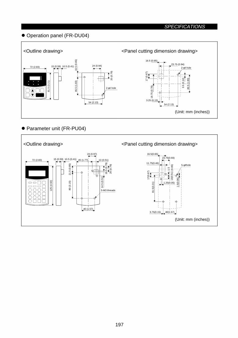
SPECIFICATIONS
197
z Operation panel (FR-DU04)
<Outline drawing>81
.5 (
3.21
)
72 (2.83) 15 (0.59) 10.5 (0.41)
20 (
0.79
)
54 (2.13)
16.5
(0.
65)
46.5
(1.
83)
24 (0.94)
2-φ4 hole
<Panel cutting dimension drawing>
19.7
5 (0
.78)
3.25 (0.13)
16.5 (0.65)
23.75 (0.94)
46.5
(1.
83)
17 (
0.67
)
54 (2.13)
2-φ4 hole
3.5
(0.1
4)
(Unit: mm (inches))
z Parameter unit (FR-PU04)
<Outline drawing>
125
(4.9
2)
72 (2.83) 15 (0.59) 10.5 (0.41)
40 (1.57)
80 (
3.15
)
45 (1.77)
24 (0.97)
13 (0.51)
20 (
0.79
)
14.5
(0.
51)
21.5
(0.
85)
5-M3 threads
18.5
(0.
79)
<Panel cutting dimension drawing>
40(1.57)
5-φ4hole11.75(0.46)
81.5
(3.2
1) 1.25(0.05)
17(0
.67)
16.5(0.65)
1.5(
0.06
)
23.75(0.93)
1.5
(
0.06
)13
(0.5
1)
3.75(0.15)
(Unit: mm (inches))

7
CHAPTER 7
OPTIONS
This chapter describes the "options" of this product.Always read the instructions before using the equipment.
7.1 Option List................................................................198
CHAPTER 1 OUTLINE
CHAPTER 2 INSTALLATION AND WIRING
CHAPTER 3 OPERATION
CHAPTER 4 PARAMETERS
CHAPTER 5 PROTECTIVE FUNCTIONS
CHAPTER 6 SPECIFICATIONS
CHAPTER 7 OPTIONS
APPENDICES

7.1 Option ListOPTIONS
198
7 OPTIONS7.1 Option List
7.1.1 Stand-alone options
Name Type Application, Specifications, etc.Applicable
InverterParameter unit(8 languages)
FR-PU04Interactive parameter unit using LCD display (For use in Japanese,English, German, French, Spanish, Italian, Swedish and Finnish)
Parameter unitconnection cable
FR-CB2 Cable for connection of the operation panel or parameter unit.
Common toall models
Cooling fin protrusionattachment
FR-A5CNUsed to place only the heat generating section of the inverter inthe back of the control box.
1.5K to 55K,according tocapacity
totally enclosedstructure specificationattachment
FR-A5CVBy installing this option, the inverter meets the totally enclosedstructure specifications (IP40).
0.4K to 22K,according tocapacity
Attachment for conduitconnection
FR-A5FN Used to connect a conduit directly.30K to 55K,according tocapacity
FR-A200E seriesinstallation interchangeattachment
FR-A5ATMounting plate used to make the mounting dimensions identical tothose of the conventional models.
0.4K to 55K,according tocapacity
EMC Directivecompatible noise filer(Note 3)
SF Noise filer conforming to the EMC Directive (EN50081-2)0.4 to 55K,according tocapacity
High-duty brakeresistor
FR-ABR-(H)(Note 1)
Used to improve the braking capability of the brake built in theinverter.
0.4K to 7.5K,according tocapacity
Surge voltagesuppressing filter
FR-ASF-H Suppresses surge voltages on the inverter output side.0.4 to 55K,according tocapacity
Power factor improvingDC reactor
FR-BEL-(H)(Note 1)
Used to improve the inverter input power factor (overall powerfactor about 95%) and cooperate with the power supply.
0.4K to 55K,according tocapacity
Power factor improvingAC reactor
FR-BAL-(H)(Note 1)
Used to improve the inverter input power factor (overall powerfactor about 90%) and cooperate with the power supply.
0.4K to 55K,according tocapacity
Radio noise filterFR-BIF-(H)(Note 1)
For radio noise reduction
FR-BSF01For line noise reduction (applies to small capacities of 3.7kW orless)Line noise filter
FR-BLF For line noise reduction
Common toall models
BU brake unitBU-1500 to 15K,H7.5K to H30K
Used to improve the braking capability of the inverter (for high-inertia load or negative load).
Brake unitFR-BU-15K to 55K,H15K to H55K
Resistor unitFR-BR-15K to 55K,H15K to H55K
Used to improve the braking capability of the inverter (for high-inertia load or negative load). Use the brake unit and resistor unittogether.
Power return converterFR-RC-15K to 55K,H15K to H55K
High-function brake unit which can return motor-generated brakingenergy to the power supply.
High power factorconverter
FR-HC7.5K to 55K,H7.5K to H55K
The high power factor converter switches the converter circuit on-off to convert the input current waveform into a sine wave tosuppress harmonics considerably. (Used with the standardaccessories.)
According tocapacity
Manual controller FR-AX (Note 4)For independent operation. With frequency meter, frequencysetting potentiometer and start switch.
DC tach. follower FR-AL (Note 4)For joint operation using external signals. (0 to 5VDC, 0 to 10VDC)(1VA) (Note 2)
Three speed selector FR-AT (Note 4) For three-speed (high, middle, low) switching operation. (1.5VA)
Motorized speed setter FR-FK (Note 4)For remote operation. Allows operation to be controlled fromseveral places. (5VA)
Ratio setter FR-FH (Note 4) For ratio control. Allows ratios to be set to five inverters. (3VA)
Common toall models

OPTIONS
199
Name Type Application, Specifications, etc.Applicable
Inverter
PG follower (Note 4) FR-FPFor follow-up operation using the signal of a pilotgenerator (PG). (2VA)
Master controller (Note 4) FR-FGFor parallel operation of several (up to 35) inverters.(5VA)
Soft starter (Note 4) FR-FCFor soft start and stop. Allows parallel operation andacceleration/deceleration. (3VA)
Deviation detector (Note 4) FR-FDFor synchronous operation. Used with a deviation sensorand synchro. (5VA)
Preamplifier (Note 4) FR-FACan be used as A/V conversion or operational amplifier.(3VA)
Pilot generator (Note 4) QVAH-10 For follow-up operation. 70/35VAC 500Hz (at 2500rpm)
Deviation sensor (Note 4) YVGC-500W-NSFor synchronous operation (mechanical deviationdetection). Output 90VAC/90°
Frequency settingpotentiometer (Note 4)
WA2W1kΩ For frequency setting. Wire-wound type. 2W1KΩ Bcharacteristic.
Frequency meter (Note 4) YM206RI1mADedicated frequency meter (up to 120Hz scale). Moving-coil DC ammeter.
Calibration resistor (Note 4) RV24YN10kΩ For calibration of the frequency meter. Carbon-film type.B characteristic.
Inverter setup software FR-SW0-SETUP-WESupports steps from inverter start-up to maintenance.(FR-SW0-SETUP-WJ is Japanese version.)
Common toall models
Note: 1. "H" in the type code indicates 400V class.Power supply specifications of FR series controllersand setters: 200VAC 50Hz, 200V/220VAC 60Hz, 115VAC 60Hz.
2. Rated power consumption3. The intercompatibility attachment (FR-A5AT) is required to mount the inverter, with the
exception of some models.4. Options available in Japan only.

OPTIONS
200
7.1.2 Inboard dedicated options
Inboard options
Name Type Function
12-bit digital input FR-A5AXz Input interface used to set the inverter frequency accurately using external 3-digit BCD or
12-bit binary-coded digital signals.z Gains and offsets can also be adjusted.
Digital outputz Among 26 standard output signals of the inverter, this option outputs any 7 selected
signals from open collector output terminals.
Extension analogoutput
FR-A5AY z Outputs extra 16 signals which can be monitored on the FM and AM terminals such asoutput frequency,
z 20mADC or 5V(10V)DC meter can be connected.
Relay output FR-A5ARz Among 26 standard output signals of the inverter, this option outputs any 3 selected
signals from relay contact output terminals.
Orientation, PLGoutput (Note 3)
z Used with a position detector (pulse encoder) installed on a machine tool spindle to stopthe spindle in position (orientation control).
z The motor speed is detected by the pulse encoder and this detection signal is fed back tothe inverter to automatically compensate for speed variation. Hence, the motor speed canbe kept constant if load variation occurs.
z The current spindle position and actual motor speed can be monitored on the operationpanel or parameter unit.
Pulse train input
FR-A5AP
z A pulse train signal can be used to enter the speed command to the inverter.
Computer linkz Operation/monitoring/parameter change of the inverter can be performed under the control
of a user program from a computer, e.g. personal computer or FA controller, connected bya communication cable.
Relay output
FR-A5NRz Any one output signal can be selected from among the standard output signals of the
inverter and output as a relay contact (contactor) signal.
Profibus DP FR-A5NPz Operation/monitoring/parameter change of the inverter can be performed from a computer
or PLC.
Device Net TM FR-A5NDz Operation/monitoring/parameter change of the inverter can be performed from a computer
or PLC.CC-Link (Note 2) FR-A5NC z Operation/monitoring/parameter change of the inverter can be performed from a PLC.
Com
mun
icat
ion
Modbus Plus FR-A5NMz Operation/monitoring/parameter change of the inverter can be performed from a computer
or PLC.
Note: 1. Three inboard options may be mounted at the same time (the number of the same optionsmountable is only one, and only one of the communication options may be mounted.)
2. CC-Link stands for Control & Communication Link.3. The FR-A5AX (12-bit digital input) is required for orientation control.
8
APPENDICES
This chapter provides the "appendices" for use of thisproduct.Always read the instructions before using the equipment.
Appendix 1 Data Code List ..................................................201 Appendix 2 List of Parameters Classified by Purpose of Use ..................................207 Appendix 3 Operating the Inverter Using Single-Phase Power Supply ...................208
CHAPTER 1 OUTLINE
CHAPTER 2 INSTALLATION AND WIRING
CHAPTER 3 OPERATION
CHAPTER 4 PARAMETERS
CHAPTER 5 PROTECTIVE FUNCTIONS
CHAPTER 6 SPECIFICATIONS
CHAPTER 7 OPTIONS
APPENDICES

APPENDICESAPPENDICES
201
APPENDICESAppendix 1 Data Code List
Appendix 1 Data Code List
Data CodesFunc-tion
ParameterNumber
NameRead Write
Link Parameter ExtensionSetting (Data code 7F/FF)
0 Torque boost 00 80 01 Maximum frequency 01 81 02 Minimum frequency 02 82 03 Base frequency 03 83 04 Multi-speed setting (high speed) 04 84 05 Multi-speed setting (middle speed) 05 85 06 Multi-speed setting (low speed) 06 86 07 Acceleration time 07 87 08 Deceleration time 08 88 0
Bas
ic fu
nctio
ns
9 Electronic thermal O/L relay 09 89 010 DC injection brake operation frequency 0A 8A 011 DC injection brake operation time 0B 8B 012 DC injection brake voltage 0C 8C 013 Starting frequency 0D 8D 014 Load pattern selection 0E 8E 015 Jog frequency 0F 8F 016 Jog acceleration/deceleration time 10 90 017 MRS input selection 11 91 018 High-speed maximum frequency 12 92 019 Base frequency voltage 13 93 020 Acceleration/deceleration reference frequency 14 94 021 Acceleration/deceleration time increments 15 95 022 Stall prevention operation level 16 96 0
23Stall prevention operation level at doublespeed
17 97 0
24 Multi-speed setting (speed 4) 18 98 025 Multi-speed setting (speed 5) 19 99 026 Multi-speed setting (speed 6) 1A 9A 027 Multi-speed setting (speed 7) 1B 9B 028 Multi-speed input compensation 1C 9C 029 Acceleration/deceleration pattern 1D 9D 030 Regenerative function selection 1E 9E 031 Frequency jump 1A 1F 9F 032 Frequency jump 1B 20 A0 033 Frequency jump 2A 21 A1 034 Frequency jump 2B 22 A2 035 Frequency jump 3A 23 A3 036 Frequency jump 3B 24 A4 0
Sta
ndar
d op
erat
ion
func
tions
37 Speed display 25 A5 0
41 Up-to-frequency sensitivity 29 A9 0
42 Output frequency detection 2A AA 0
Out
put
term
inal
func
tions
43 Output frequency detection for reverse rotation 2B AB 0
44 Second acceleration/deceleration time 2C AC 045 Second deceleration time 2D AD 046 Second torque boost 2E AE 047 Second V/F (base frequency) 2F AF 048 Second stall prevention operation current 30 B0 049 Second stall prevention operation frequency 31 B1 0
Sec
ond
func
tions
50 Second output frequency detection 32 B2 052 DU/PU main display data selection 34 B4 053 PU level display data selection 35 B5 054 FM terminal function selection 36 B6 055 Frequency monitoring reference 37 B7 0D
ispl
ayfu
nctio
ns
56 Current monitoring reference 38 B8 0
57 Automatic restart functions 39 B9 0
Rat
edou
tput
curr
ent
58 Restart coasting time 3A BA 0

APPENDICES
202
Data CodesFunc-tion
ParameterNumber
NameRead Write
Link Parameter ExtensionSetting (Data code 7F/FF)
Add
ition
alfu
nctio
n
59 Remote setting function selection 3B BB 0
60 Intelligent mode selection 3C BC 061 Reference current 3D BD 062 Reference current for acceleration 3E BE 063 Reference current for deceleration 3F BF 064 Starting frequency for elevator mode 40 C0 065 Retry selection 41 C1 0
66Stall prevention operation level reductionstarting frequency
42 C2 0
67 Number of retries at alarm occurrence 43 C3 068 Retry waiting time 44 C4 069 Retry count display erasure 45 C5 070 Special regenerative brake duty 46 C6 071 Applied motor 47 C7 072 PWM frequency selection 48 C8 073 0-5V/0-10V selection 49 C9 074 Filter time constant 4A CA 0
75Reset selection/disconnected PU detection/PUstop selection
4B CB 0
76 Alarm code output selection 4C CC 077 Parameter write disable selection 4D None 078 Reverse rotation prevention selection 4E CE 0
Ope
ratio
n se
lect
ion
func
tions
79 Operation mode selection 4F None 080 Motor capacity 50 D0 081 Number of motor poles 51 D1 082 Motor exciting current 52 D2 083 Rated motor voltage 53 D3 084 Rated motor frequency 54 D4 089 Speed control gain 59 D9 090 Motor constant (R1) 5A DA 091 Motor constant (R2) 5B DB 092 Motor constant (L1) 5C DC 093 Motor constant (L2) 5D DD 094 Motor constant (X) 5E DE 095 Online auto tuning selection 5F DF 0
Adv
ance
d m
agne
tic fl
uxve
ctor
cont
rol
96 Auto tuning setting/status 60 E0 0100 V/F1 (first frequency) 00 80 1101 V/F1 (first frequency voltage) 01 81 1102 V/F2 (second frequency) 02 82 1103 V/F2 (second frequency voltage) 03 83 1104 V/F3 (third frequency) 04 84 1105 V/F3 (third frequency voltage) 05 85 1106 V/F4 (fourth frequency) 06 86 1107 V/F4 (fourth frequency voltage) 07 87 1108 V/F5 (fifth frequency) 08 88 1
5-po
int f
lexi
ble
V/F
char
acte
ristic
s
109 V/F5 (fifth frequency voltage) 09 89 1110 Third acceleration/deceleration time 0A 8A 1111 Third deceleration time 0B 8B 1112 Third torque boost 0C 8C 1113 Third V/F (base frequency) 0D 8D 1114 Third stall prevention operation current 0E 8E 1115 Third stall prevention operation frequency 0F 8F 1T
hird
func
tions
116 Third output frequency detection 10 90 1

APPENDICES
203
Data CodesFunc-tion
ParameterNumber
NameRead Write
Link Parameter ExtensionSetting (Data code 7F/FF)
117 Station number 11 None 1118 Communication speed 12 None 1119 Stop bit length/data length 13 None 1120 Parity check presence/absence 14 None 1121 Number of communication retries 15 None 1122 Communication check time interval 16 None 1123 Waiting time setting 17 None 1C
omm
unic
atio
nfu
nctio
ns
124 CR, LF presence/absence selection 18 None 1128 PID action selection 1C 9C 1129 PID proportional band 1D 9D 1130 PID integral time 1E 9E 1131 Upper limit 1F 9F 1132 Lower limit 20 A0 1133 PID action set point for PU operation 21 A1 1P
ID c
ontr
ol
134 PID differential time 22 A2 1
135Commercial power supply-inverter switch-oversequence output terminal selection
23 A3 1
136 MC switch-over interlock time 24 A4 1137 Start waiting time 25 A5 1
138Commercial power supply-inverter switch-overselection at alarm occurrence
26 A6 1
Com
mer
cial
pow
ersu
pply
-inve
rter
switc
h-ov
er
139Automatic inverter-commercial power supplyswitch-over frequency
27 A7 1
140 Backlash acceleration stopping frequency 28 A8 1
141 Backlash acceleration stopping time 29 A9 1
142 Backlash deceleration stopping frequency 2A AA 1
Bac
klas
h
143 Backlash deceleration stopping time 2B AB 1
144 Speed setting switch-over 2C AC 1Dis-play 145 Parameter unit language switch-over
148 Stall prevention level at 0V input 30 B0 1
Add
it-io
nal
func
tions
149 Stall prevention level at 10V input 31 B1 1
150 Output current detection level 32 B2 1
151 Output current detection period 33 B3 1
152 Zero current detection level 34 B4 1
Cur
rent
dete
ctio
n
153 Zero current detection period 35 B5 1
154Voltage reduction selection during stallprevention operation
36 B6 1
155 RT activated condition 37 B7 1156 Stall prevention operation selection 38 B8 1157 OL signal waiting time 39 B9 1
Sub
func
tions
158 AM terminal function selection 3A BA 1
Add
ition
alfu
nctio
n
160 User group read selection 00 80 2
162Automatic restart after instantaneous powerfailure selection
02 82 2
163 First cushion time for restart 03 83 2
164 First cushion voltage for restart 04 84 2
Res
tart
afte
rin
stan
tane
ous
pow
er fa
ilure
165 Restart stall prevention operation level 05 85 2
170 Watt-hour meter clear 0A 8A 2
Initi
alm
onito
r
171 Actual operation hour meter clear 0B 8B 2
173 User group 1 registration 0D 8D 2
174 User group 1 deletion 0E 8E 2
175 User group 2 registration 0F 8F 2Use
rfu
nctio
ns
176 User group 2 deletion 10 90 2

APPENDICES
204
Data CodesFunc-tion
ParameterNumber
NameRead Write
Link Parameter ExtensionSetting (Data code 7F/FF)
180 RL terminal function selection 14 94 2181 RM terminal function selection 15 95 2182 RH terminal function selection 16 96 2183 RT terminal function selection 17 97 2184 AU terminal function selection 18 98 2185 JOG terminal function selection 19 99 2186 CS terminal function selection 1A 9A 2190 RUN terminal function selection 1E 9E 2191 SU terminal function selection 1F 9F 2192 IPF terminal function selection 20 A0 2193 OL terminal function selection 21 A1 2194 FU terminal function selection 22 A2 2T
erm
inal
ass
ignm
ent f
unct
ions
195 ABC terminal function selection 23 A3 2
Add
ition
alfu
nctio
n
199 User's initial value setting 27 A7 2
200Programmed operation minute/secondselection
3C BC 1
201 Program setting 1 3D BD 1202 Program setting 1 3F BE 1203 Program setting 1 3F BF 1204 Program setting 1 40 C1 1205 Program setting 1 41 C1 1206 Program setting 1 42 C2 1207 Program setting 1 43 C3 1208 Program setting 1 44 C4 1209 Program setting 1 45 C5 1210 Program setting 1 46 C6 1211 Program setting 2 47 C7 1212 Program setting 2 48 C8 1213 Program setting 2 49 C9 1214 Program setting 2 4A CA 1215 Program setting 2 4B CB 1216 Program setting 2 4C CC 1217 Program setting 2 4D CD 1218 Program setting 2 4E CE 1219 Program setting 2 4F CF 1220 Program setting 2 50 D0 1221 Program setting 3 51 D1 1222 Program setting 3 52 D2 1223 Program setting 3 53 D3 1224 Program setting 3 54 D4 1225 Program setting 3 55 D5 1226 Program setting 3 56 D6 1227 Program setting 3 57 D7 1228 Program setting 3 58 D8 1229 Program setting 3 59 D9 1230 Program setting 3 5A DA 1
Pro
gram
med
ope
ratio
n
231 Timer setting 5B DB 1232 Multi-speed setting (speed 8) 28 A8 2233 Multi-speed setting (speed 9) 29 A9 2234 Multi-speed setting (speed 10) 2A AA 2235 Multi-speed setting (speed 11) 2B AB 2236 Multi-speed setting (speed 12) 2C AC 2237 Multi-speed setting (speed 13) 2D AD 2238 Multi-speed setting (speed 14) 2E AE 2
Mul
ti-sp
eed
oper
atio
n
239 Multi-speed setting (speed 15) 2F AF 2

APPENDICES
205
Data CodesFunc-tion
ParameterNumber
NameRead Write
Link Parameter ExtensionSetting (Data code 7F/FF)
240 Soft-PWM setting 30 B0 2
Sub
func
tion
244 Cooling fan operation selection 34 B4 2
Sto
pse
lect
ion
func
tion
250 Stop selection 3A BA 2
251 Output phase failure protection selection 3B BB 2
252 Override bias 3C BC 2
Add
ition
alfu
nctio
n
253 Override gain 3D BD 2
261 Power failure stop selection 45 C5 2262 Subtracted frequency at deceleration start 46 C6 2263 Subtraction starting frequency 47 C7 2264 Power-failure deceleration time 1 48 C8 2265 Power-failure deceleration time 2 49 C9 2
Pow
er fa
ilure
stop
func
tions
266Power-failure deceleration time switch-overfrequency 4A CA 2
Fun
ctio
nse
lect
ion
270Stop-on-contact/load torque high-speedfrequency control selection 53 CE 2
271 High-speed setting maximum current 45 CF 2
272 Mid-speed setting minimum current 46 D0 2
273 Current averaging range 47 D1 2
Hig
h sp
eed
freq
uenc
yco
ntro
l
274 Current averaging filter constant 48 D2 2
275Stop-on-contact exciting current low-speedmultiplying factor 53 D3 2
Sto
p on
cont
act
276 Stop-on-contact PWM carrier frequency 54 D4 2
278 Brake opening frequency 56 D6 2279 Brake opening current 57 D7 2280 Brake opening current detection time 58 D8 2281 Brake operation time at start 59 D9 2282 Brake operation frequency 5A DA 2283 Brake operation time at stop 5B DB 2284 Deceleration detection function selection 5C DC 2B
rake
seq
uenc
efu
nctio
ns
285 Overspeed detection frequency 5D DD 2
286 Droop gain SE DE 2
Dro
opco
ntro
l
287 Droop filter constant SF DF 2
300 BCD code input bias 00 80 3301 BCD code input gain 01 81 3302 Binary input bias 02 82 3303 Binary input gain 03 83 3
304Selection of whether digital input and analogcompensation input are enabled or disabled 04 84 312
-bit
digi
tal
inpu
t
305 Data read timing signal on/off selection 05 85 3306 Analog output signal selection 06 86 3307 Setting for zero analog output 07 87 3308 Setting for maximum analog output 08 88 3
309Analog output signal voltage/current switch-over
09 89 3
310 Analog meter voltage output selection 0A 8A 3311 Setting for zero analog meter voltage output 0B 8B 3
312 Setting for maximum analog meter voltageoutput 0C 8C 3
313 Y0 output selection 0D 8D 3314 Y1 output selection 0E 8E 3315 Y2 output selection 0F 8F 3316 Y3 output selection 10 90 3
Ana
log
outp
ut, d
igita
l out
put
317 Y4 output selection 11 91 3

APPENDICES
206
Data CodesFunc-tion
ParameterNumber
NameRead Write
Link Parameter ExtensionSetting (Data code 7F/FF)
318 Y5 output selection 12 92 3
Ana
log
outp
ut, d
igita
lou
tput
319 Y6 output selection 13 93 3
320 RA1 output selection 14 94 3
321 RA2 output selection 15 95 3
Rel
ayou
tput
322 RA3 output selection 16 96 3
330 RA output selection 1E 9E 3331 Inverter station number 1F 9F 3332 Communication speed 20 A0 3333 Stop bit length 21 A1 3334 Parity check yes/no 22 A2 3335 Communication retry count 23 A3 3336 Communication check time interval 24 A4 3337 Waiting time setting 25 A5 3338 Operation command right 26 A6 3339 Speed command right 27 A7 3340 Link start mode selection 28 A8 3341 CR, LF yes/no selection 29 A9 3
Com
pute
r lin
k fu
nctio
n
342 E2PROM write yes/no 2A AA 3900 FM terminal calibration 5C DC 1901 AM terminal calibration 5D DD 1902 Frequency setting voltage bias 5E DE 1903 Frequency setting voltage gain 5F DF 1904 Frequency setting current bias 60 E0 1905 Frequency setting current gain 61 E1 1
Cal
ibra
tion
func
tions
990 Buzzer control 5A DA 9 Second parameter switch-over 6C EC
Running frequency (RAM) 6D ED
Fre
quen
cyse
tting
Running frequency (E2PROM) 6E EE
Monitor 6F Output current monitor 70 Output voltage monitor 71 Special monitor 72
Fre
quen
cym
onito
r
Special monitor selection No. 73 F3
Most recent No. 1, No. 2/alarm displayclear
74 F4
Most recent No. 3, No. 4 75 Most recent No. 5, No. 6 76
Ala
rmdi
spla
y
Most recent No. 7, No. 8 77 Inverter status monitor/run command 7A FA Operation mode acquisition 7B FB All clear FC Inverter reset FD Link parameter extension setting 7F FF

APPENDICES
207
Appendix 2 List of Parameters Classified by Purposes of Use
Appendix 2 List of Parameters Classified by Purposes of Use
Set the parameters according to the operating conditions. The following list indicates purposes of use andparameters. (For full information on the parameters, Refer to Chapter 4.)
Parameter NumbersPurpose of Use
Parameter numbers which must be setAdjustment of acceleration/deceleration time andpattern
Pr. 7, Pr. 8, Pr. 20, Pr. 21
Motor overheat protection Pr. 9Selection of optimum output characteristic for loadcharacteristic
Pr. 3
Limit of output frequency Pr. 1, Pr. 2, Pr. 18Operation over 60Hz Pr. 903, Pr. 905Adjustment of frequency setting signal and output Pr. 73, Pr. 902, Pr. 903, Pr. 904, Pr. 905Calibration of frequency meter Pr. 54, Pr. 55, Pr. 56, Pr. 158, Pr. 900Adjustment of digital frequency meter Pr. 54, Pr. 55, Pr. 56, Pr. 900Adjustment of motor output torque Pr. 0, Pr. 80, Pr. 81
Multi-speed operationPr. 4, Pr. 5, Pr. 6, Pr. 24, Pr. 25, Pr. 26, Pr. 27, Pr. 232,Pr. 234, Pr. 235, Pr. 236, Pr. 237, Pr. 238, Pr. 239
Jog operation Pr. 15, Pr. 16Frequency jump operation Pr. 31, Pr. 32, Pr. 33, Pr. 34, Pr. 35, Pr. 36Reversible operation according to analog signal polarity Pr. 28, Pr. 73Automatic restart after instantaneous power failure Pr. 57, Pr. 58Adjustment of brake operation Pr. 10, Pr. 11, Pr. 12Timing of magnetic brake operation Pr. 42,Display of speed, etc. Pr. 37, Pr. 52, Pr. 53Function rewrite prevention Pr. 77Reverse rotation prevention Pr. 78Optimum acceleration/deceleration within continuousrating range
Pr. 60
Energy-saving operation Pr. 60Automatic restart after alarm stop Pr. 65, Pr. 67, Pr. 68, Pr. 69
Sub-motor operationPr. 0, Pr. 3, Pr. 7, Pr. 8, Pr. 44, Pr. 45, Pr. 46, Pr. 47, Pr.110, Pr. 111, Pr. 112, Pr. 113
To make desired output characteristics (V/F pattern) Pr. 100 to Pr. 109Operation via communication with personal computer Pr. 117 to Pr. 124Operation under PID control Pr. 128 to Pr. 134To perform commercial power supply-inverter switch-over operation
Pr. 135 to Pr. 139
To make backlash compensation Pr. 140 to Pr. 143To detect current Pr. 150 to Pr. 153Assignment of input terminal functions Pr. 180 to Pr. 186Assignment of output terminal functions Pr. 190 to Pr. 195To suppress noise Pr. 72, Pr. 240To group parameters Pr. 160, Pr. 173 to Pr. 176To set initial values for parameters Pr. 199Clearing of inverter's actual operation time Pr. 171High-speed frequency control operation Pr. 271 to Pr. 274To exercise stop-on-contact control Pr. 275, Pr. 276To increase cooling fan life Pr. 244To decelerate inverter to a stop at power failure Pr. 261 to Pr. 266Advanced magnetic flux vector control operation Pr. 80, Pr. 81Programmed operation Pr. 200 to Pr. 231Selection of key beep Pr. 990

APPENDICES
208
Appendix 3 Operating the Inverter Using a Single-Phase Power Supply
Appendix 3 Operating the Inverter Using a Single-Phase Power Supply
If a single-phase power supply is used to operate the inverter only 4 of the 6 of the diodes will be used.Therefore the ripple current of the capacitor will increase when compared to operation from a three-phasepower supply, resulting in a higher temperature rise of the converter and the capacitor. Operating the inverterusing a single-phase power supply requies derating of the output current.
yRating for inverter operation using single-phase power supplyType FR-A520-K 0.4 0.75 1.5 2.2 3.7
Continuous current(Constant Torque)
1.5 2.5 4 5 7
Out
-pu
t
Voltage (Note 1) Three phase, 200 to 220V 50Hz, 200 to 240V 60HzRated input AC current (A)(Single phase)
4.5 6.4 11.2 12.9 17.4
Rated input AC voltage Single phase, 200 to 220V 50Hz, 200 to 240V 60Hz
Pow
ersu
pply
Power supply systemcapacty (kVA) (Note 2)
1.5 2.5 4.5 5.5 9
(Note 1) The maximum output voltage cannot exceed the power supply voltage. The maximum outputvoltage may be set as desired below supply voltage.
(Note 2) The power supply capacity changes with the values of power supply side inverter impedance(including those of the input reactor and cables).
yCautions on operating the inverter using single-phase power supply(1)Connect the single-phase power supply to the terminals R and S of the inverter.(2) If the capacity of the power supply is insufficient, the output voltage will become unstable under changing
load conditions. Therefore, be certain the power supply is adequate.
<Example circuit>
R
S
T
U
V
W
IM
InverterNFB
Motor
STF (STR)
SD Grounding
Power supplySingle phase
AC200 - 220V 50HzAC200 - 240V 60Hz
Start signal
Note: Only the NA version A500 is UL listed for the above single-phase ratings.The A500 inverter is not CE marked for single-phase operation. The A500 is not EMC compliant forsingle-phase operation.

REVISIONS* The manual number is given on the bottom left of the back cover.
Print Data *Manual Number Revision
Sep., 1997 IB(NA)-66790-A First edition
Oct., 1997 IB(NA)-66790-B Partly modifiedFront cover
Nov., 1997 IB(NA)-66790-C Additions
z Instructions for Standard-compliant products (pages 38, 39)z FR-A540-30K to 55K
Modifications
z Pr. 902 to Pr. 905 <adjustment procedure>z External optionsz Dedicated inboard options
Mar., 1998 IB(NA)-66790-D Additions
z In accordance with NA and EC
Modifications
z In accordance with Standard-compliant modelsz User group settingz Input terminal function selection
Oct., 1998 IB(NA)-66790-E Additions
z Description of the data line filter
Partial additions
z Alarm displays (E.E6, E.E7)
Modifications
z Change in ground terminal position of FR-A520-0.4K, 0.75Kz Change in ground terminal screw size of FR-A520-5.5K, 7.5Kz About RS-485/RS-232C converter


![Um Performer A520 A530 A540 Tw[1]](https://img.pdfslide.net/doc/110x75/5492a7b5ac7959482e8b465c/um-performer-a520-a530-a540-tw1.jpg)