Embed Size (px)
Citation preview
Editor: Laura White [email protected] www.outotec.com
ISSUE 32December 2012OUTOTEC SEAP (SOUTH EAST ASIA PACIFIC) eNEWSLETTER
CONTENTSHIGmill - High Intensity Grinding / 1
Product News: Ø40’ SAG mill / 6
Case Study: Assarel Medet / 7
Business News: Backfill Specialists acquisition / 11
VPF technology / 12
Product News: Reline Machines / 16
It is a well recognised fact that global ore grades are declining while commodity demands continue to rise. These ore bodies are increasingly complex, requiring a finer grind size for maximum mineral recovery and grade and are setting new challenges, particularly for grinding technology. Energy efficiency is a major driving force and another challenge to address.
The High Intensity Grinding (HIG) mill has been designed specifically to manage these type of complex,
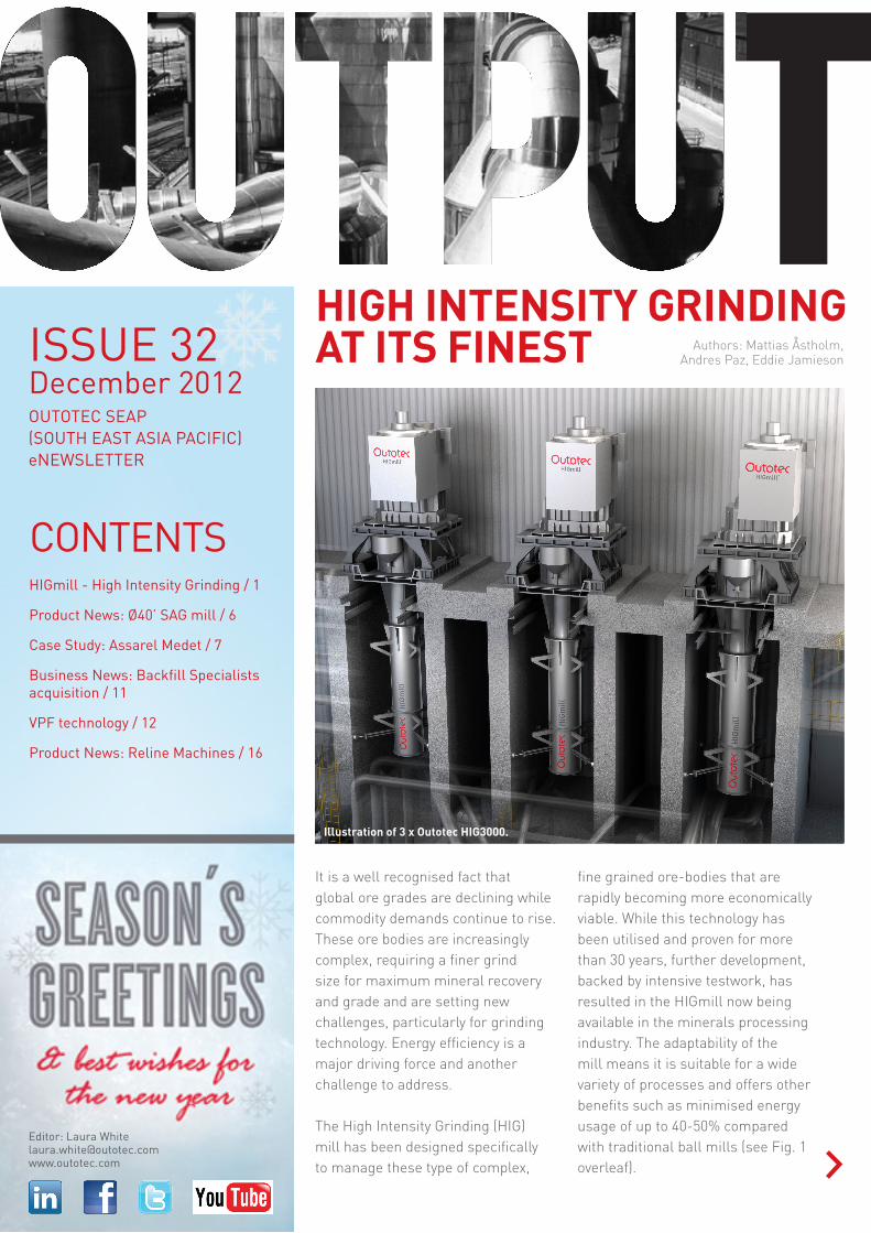
fine grained ore-bodies that are rapidly becoming more economically viable. While this technology has been utilised and proven for more than 30 years, further development, backed by intensive testwork, has resulted in the HIGmill now being available in the minerals processing industry. The adaptability of the mill means it is suitable for a wide variety of processes and offers other benefits such as minimised energy usage of up to 40-50% compared with traditional ball mills (see Fig. 1 overleaf).
HIGH INTENSITY GRINDING AT ITS FINEST Authors: Mattias Åstholm,
Andres Paz, Eddie Jamieson
Illustration of 3 x Outotec HIG3000.
Output SEAP December 2012 / 2
GRINDING EFFICIENCY
In a typical application, the HIG process begins with the circuit feed being pumped to a scalping cyclone upstream of the mill which ensures a tighter product specification and defines the pulp density. The defined underflow is then mixed with water to optimal grinding density and pumped into the mill at base level. The slurry enters a grinding chamber containing grinding media and rotating discs which provide momentum to stir the charge against a series of static discs.
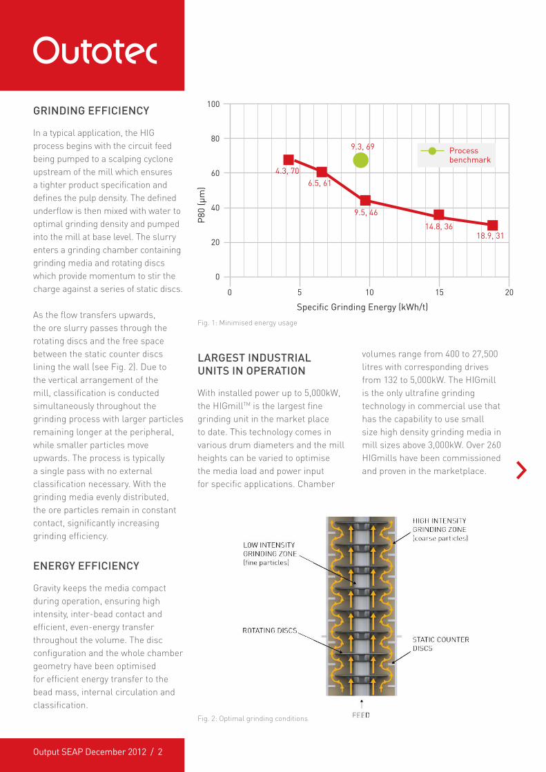
As the flow transfers upwards, the ore slurry passes through the rotating discs and the free space between the static counter discs lining the wall (see Fig. 2). Due to the vertical arrangement of the mill, classification is conducted simultaneously throughout the grinding process with larger particles remaining longer at the peripheral, while smaller particles move upwards. The process is typically a single pass with no external classification necessary. With the grinding media evenly distributed, the ore particles remain in constant contact, significantly increasing grinding efficiency.
ENERGY EFFICIENCY
Gravity keeps the media compact during operation, ensuring high intensity, inter-bead contact and efficient, even-energy transfer throughout the volume. The disc configuration and the whole chamber geometry have been optimised for efficient energy transfer to the bead mass, internal circulation and classification.
Fig. 1: Minimised energy usage
LARGEST INDUSTRIAL UNITS IN OPERATION
With installed power up to 5,000kW, the HIGmillTM is the largest fine grinding unit in the market place to date. This technology comes in various drum diameters and the mill heights can be varied to optimise the media load and power input for specific applications. Chamber
volumes range from 400 to 27,500 litres with corresponding drives from 132 to 5,000kW. The HIGmill is the only ultrafine grinding technology in commercial use that has the capability to use small size high density grinding media in mill sizes above 3,000kW. Over 260 HIGmills have been commissioned and proven in the marketplace.
100
80
60
P80
(µm
)
Specific Grinding Energy (kWh/t)
40
20
0
0
4.3, 706.5, 61
9.5, 46
9.3, 69
14.8, 3618.9, 31
105 15 20
Process benchmark
Fig. 2: Optimal grinding conditions
Output SEAP December 2012 / 3
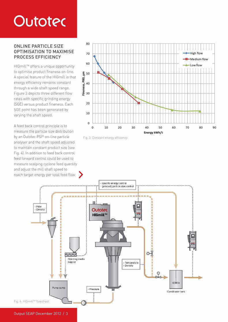
Fig. 3: Constant energy efficiency
Fig. 4: HIGmillTM flowsheet
0
10
20
30
40
50
60
70
80
0 10 20 30 40 50 60 70 80 90
Fine
ness
, P80
, µm
Energy kWh/t
High flow
Medium flow
Low flow
ONLINE PARTICLE SIZE OPTIMISATION TO MAXIMISE PROCESS EFFICIENCY
HIGmillTM offers a unique opportunity to optimise product fineness on-line. A special feature of the HIGmill is that energy efficiency remains constant through a wide shaft speed range. Figure 3 depicts three different flow rates with specific grinding energy (SGE) versus product fineness. Each SGE point has been generated by varying the shaft speed.
A feed back control principle is to measure the particle size distribution by an Outotec PSI® on-line particle analyser and the shaft speed adjusted to maintain constant product size (see Fig. 4). In addition to feed back control feed forward control could be used to measure scalping cyclone feed quantity and adjust the mill shaft speed to reach target energy per total feed flow.
Output SEAP December 2012 / 4
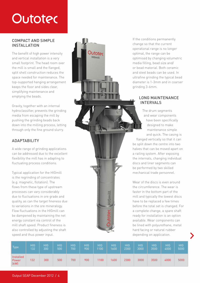
COMPACT AND SIMPLE INSTALLATION
The benefit of high power intensity and vertical installation is a very small footprint. The head room over the mill is small and the flanged, split shell construction reduces the space needed for maintenance. The top-supported hanging arrangement keeps the floor and sides clear, simplifying maintenance and emptying the beads.
Gravity, together with an internal hydroclassifier, prevents the grinding media from escaping the mill by pushing the grinding beads back down into the milling process, letting through only the fine ground slurry.
ADAPTABILITY
A wide range of grinding applications can be addressed due to the excellent flexibility the mill has in adapting to fluctuating process conditions.
Typical application for the HIGmill is the regrinding of concentrates (e.g. magnetic, flotation). The flows from these type of upstream processes can vary considerably due to fluctuations in ore grade and quality, as can the target fineness due to variations in the ore mineralogy. Flow fluctuations in the HIGmill can be dampened by maintaining the net energy constant via control of the mill shaft speed. Product fineness is also controlled by adjusting the shaft speed and thus power input.
If the conditions permanently change so that the current operational range is no longer optimal, the range can be optimised by changing volumetric media filling, bead size and/or bead material. Both ceramic and steel beads can be used. In ultrafine grinding the typical bead diameter is 1-3mm and in coarser grinding 3-6mm.
LONG MAINTENANCE INTERVALS
The drum segments and wear components
have been specifically designed to make maintenance simple and quick. The casing is
flanged vertically so that it can be split down the centre into two halves that can be moved apart on a railing system. After exposing the internals, changing individual discs and liner segments can be performed by two skilled mechanical trade personnel.
Wear of the discs is even around the circumference. The wear is faster in the bottom part of the mill and typically the lowest discs have to be replaced a few times before the total set is changed. For a complete change, a spare shaft ready for installation is an option available. Wear components can be lined with polyurethane, metal hard facing or natural rubber depending on application.
InstalledPower (kW)
Type
132
HIG132
500300
HIG300
700
HIG500
900
HIG700
1100
HIG900
1600
HIG1100
2300
HIG1600
3000
HIG2300
3500
HIG3000
4000
HIG3500
5000
HIG5000
HIG4000
Output SEAP December 2012 / 5
HIGMILL DELIVERY
The HIGmills are available with or without a mounting frame. Mills in brownfield projects are typically supplied with a frame, while mills in green field projects are integrated into the concentrator building.
TYPICAL DELIVERY INCLUDES:
� Scalping cyclone with feed pump � Feed, mixing and storage tanks � Feed pump � Media addition systems for
grinding media � Motor and drive components � Gearbox and oil supply system � All instrumentation, controls and
the motor control centre � PLC control with human machine
interface (HMI) � Vertical process package
engineering and plant model
SUMMARY
This innovative and unique grinding technology provides advanced, energy efficient fine and ultra-fine grinding - particularly important for today’s more challenging ore
bodies. Suitable in either green or brownfield applications with its small footprint and high adaptability to process variations, HIG technology, at up to 5,000kW, delivers the highest installed power in the market place to date.
About the authors...Mattias Åstholm recently joined Outotec, taking on the role of Technology manager (HIGmills). Mattias has a Bachelor degree in Mining from the School of Mining, Filipstad, Sweden.
Andres Paz has a Bachelor degree in Engineering (Chemical Engineering) from Curtin University, Perth, Australia. Since 2008 Andres has had various roles for Outotec in Process Equipment Testwork and Sales. Andres’ current role is Process Engineer (Comminution) for the Grinding Mill product line.
Eddie Jamieson has a Bachelor degree in Science (Extractive Metallurgy) from Murdoch University of Perth, Australia. Since 2003 Eddie has had various roles for Outotec in Metallurgy, Project Management and Sales having previously spent a number of years as a Metallurgist on various sites in Australia and overseas. Eddie is currently the Principal Metallurgist (Comminution) for the Grinding Mill product line.
If you would like more information, click here to [email protected]
Technical Flotation Seminar
To be held in Brisbane in February - details to be confirmed
nearer the date.
To register your interest please contact: e: [email protected] ph: 02 9984 2513
Output SEAP December 2012 / 6
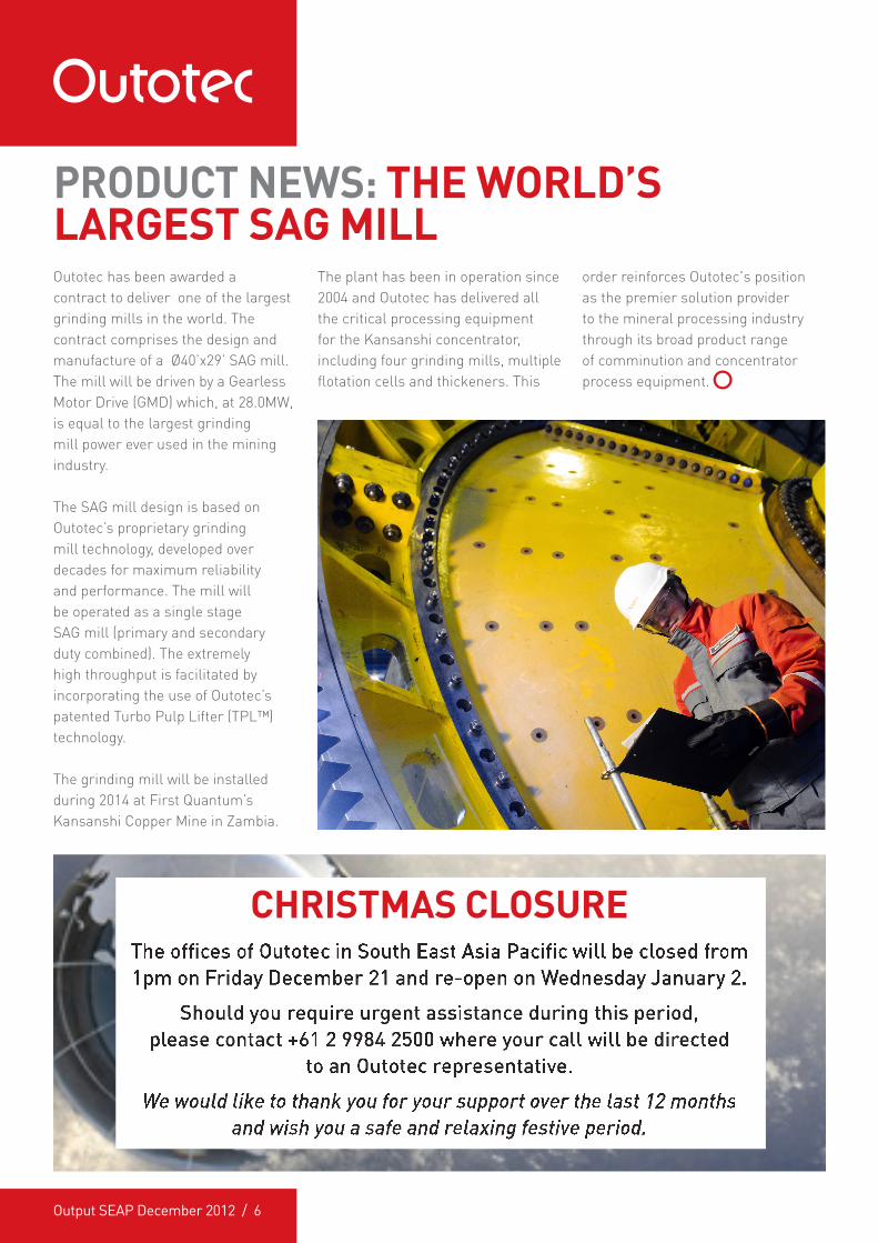
Outotec has been awarded a contract to deliver one of the largest grinding mills in the world. The contract comprises the design and manufacture of a Ø40’x29’ SAG mill. The mill will be driven by a Gearless Motor Drive (GMD) which, at 28.0MW, is equal to the largest grinding mill power ever used in the mining industry.
The SAG mill design is based on Outotec’s proprietary grinding mill technology, developed over decades for maximum reliability and performance. The mill will be operated as a single stage SAG mill (primary and secondary duty combined). The extremely high throughput is facilitated by incorporating the use of Outotec’s patented Turbo Pulp Lifter (TPL™) technology.
The grinding mill will be installed during 2014 at First Quantum’s Kansanshi Copper Mine in Zambia.
The plant has been in operation since 2004 and Outotec has delivered all the critical processing equipment for the Kansanshi concentrator, including four grinding mills, multiple flotation cells and thickeners. This
PRODUCT NEWS: THE WORLD’S LARGEST SAG MILL
order reinforces Outotec's position as the premier solution provider to the mineral processing industry through its broad product range of comminution and concentrator process equipment.
CHRISTMAS CLOSURE
Output SEAP December 2012 / 7
Assarel-Medet JSC Mining and Processing Complex is the first, largest and leading Bulgarian company for open pit mining and the processing of copper ores, providing around 50% of the national production of copper. Assarel-Medet JSC processes approximately 13 million tonnes of ore per year.
PROJECT OVERVIEW
Assarel-Medet JSC owns and operates a copper mine and concentrator in Panagyurishte, Bulgaria. The rural facility occupies a 20 hectare site, 90km south-east of Bulgaria’s capital city Sofia. Concentrator production was approximately 50,000tpa copper in concentrate, with the waste and side rock processed via dump leaching and cementation. At capacity, the old process was producing low commodity, cemented copper containing 60-80% Cu.
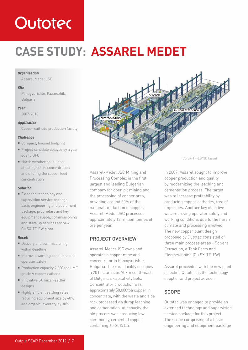
Cu SX-TF-EW 3D layout
In 2007, Assarel sought to improve copper production and quality by modernizing the leaching and cementation process. The target was to increase profitability by producing copper cathodes, free of impurities. Another key objective was improving operator safety and working conditions due to the harsh climate and processing involved. The new copper plant design proposed by Outotec consisted of three main process areas - Solvent Extraction, a Tank Farm and Electrowinning (Cu SX-TF-EW).
Assarel proceeded with the new plant, selecting Outotec as the technology supplier and project advisor.
SCOPE
Outotec was engaged to provide an extended technology and supervision service package for this project. The scope comprising of a basic engineering and equipment package
CASE STUDY: ASSAREL MEDET
OrganisationAssarel Medet JSC
SitePanagyurishte, Pazardzhik, Bulgaria
Year2007-2010
ApplicationCopper cathode production facility
Challenge � Compact, housed footprint
� Project schedule delayed by a year due to GFC
� Harsh weather conditions affecting solids concentration and diluting the copper feed concentration
Solution � Extended technology and supervision service package, basic engineering and equipment package, proprietary and key equipment supply, commissioning and start-up services for new Cu SX-TF-EW plant.
Result � Delivery and commissioning within deadline
� Improved working conditions and operator safety
� Production capacity 2,000 tpa LME grade A copper cathode
� Innovative SX mixer-settler designs
� Highly efficient settling rates reducing equipment size by 40% and organic inventory by 30%
Output SEAP December 2012 / 8
for the new copper plant, plus detail design of the Outotec proprietary equipment and delivery of all process equipment. Additionally, the scope extended to include the plant automation system and auxiliaries, such as a pressure air compressor, safety showers and storage tanks.
Within the scope of the extended package, Outotec oversaw and reviewed the detail engineering and construction carried out by the client’s own contractors. The Outotec team also assisted Assarel to specify the demi-water process and the Pregnant Leaching Solution (PLS), purification, heating and fire protection system. To ensure a seamless operation, the client opted for a full training service package, commissioning and start-up services, with post-commissioning support via remote connection between Outotec and the Assarel Cu plant automation system.
The majority of Outotec’s equipment, including process tanks and settler parts, were shipped to Bulgaria as prefabricated modules, greatly reducing construction on site, so negating potential issues with weather and space restrictions. Transformer-rectifiers, electrolyte filters, mixer-settler separation fences and electrowinning cells were also shipped from overseas.
CHALLENGES
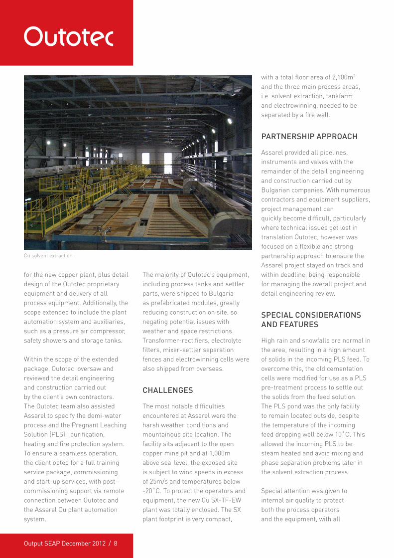
The most notable difficulties encountered at Assarel were the harsh weather conditions and mountainous site location. The facility sits adjacent to the open copper mine pit and at 1,000m above sea-level, the exposed site is subject to wind speeds in excess of 25m/s and temperatures below -20�C. To protect the operators and equipment, the new Cu SX-TF-EW plant was totally enclosed. The SX plant footprint is very compact,
with a total floor area of 2,100m2 and the three main process areas, i.e. solvent extraction, tankfarm and electrowinning, needed to be separated by a fire wall.
PARTNERSHIP APPROACH
Assarel provided all pipelines, instruments and valves with the remainder of the detail engineering and construction carried out by Bulgarian companies. With numerous contractors and equipment suppliers, project management can quickly become difficult, particularly where technical issues get lost in translation Outotec, however was focused on a flexible and strong partnership approach to ensure the Assarel project stayed on track and within deadline, being responsible for managing the overall project and detail engineering review.
SPECIAL CONSIDERATIONS AND FEATURES
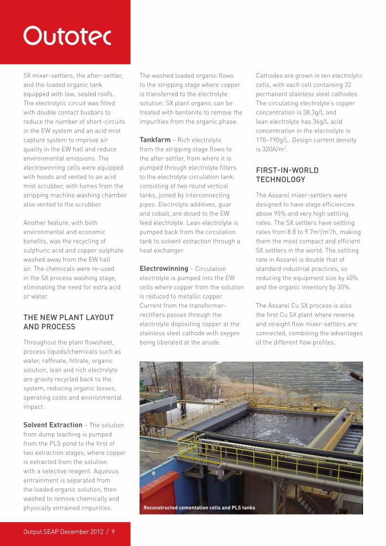
High rain and snowfalls are normal in the area, resulting in a high amount of solids in the incoming PLS feed. To overcome this, the old cementation cells were modified for use as a PLS pre-treatment process to settle out the solids from the feed solution. The PLS pond was the only facility to remain located outside, despite the temperature of the incoming feed dropping well below 10�C. This allowed the incoming PLS to be steam heated and avoid mixing and phase separation problems later in the solvent extraction process.
Special attention was given to internal air quality to protect both the process operators and the equipment, with all
Cu solvent extraction
Output SEAP December 2012 / 9
SX mixer-settlers, the after-settler, and the loaded organic tank equipped with low, sealed roofs. The electrolytic circuit was fitted with double contact busbars to reduce the number of short-circuits in the EW system and an acid mist capture system to improve air quality in the EW hall and reduce environmental emissions. The electrowinning cells were equipped with hoods and vented to an acid mist scrubber, with fumes from the stripping machine washing chamber also vented to the scrubber.
Another feature, with both environmental and economic benefits, was the recycling of sulphuric acid and copper sulphate washed away from the EW hall air. The chemicals were re-used in the SX process washing stage, eliminating the need for extra acid or water.
THE NEW PLANT LAYOUT AND PROCESS
Throughout the plant flowsheet, process liquids/chemicals such as water, raffinate, filtrate, organic solution, lean and rich electrolyte are gravity recycled back to the system, reducing organic losses, operating costs and environmental impact.
Solvent Extraction – The solution from dump leaching is pumped from the PLS pond to the first of two extraction stages, where copper is extracted from the solution with a selective reagent. Aqueous entrainment is separated from the loaded organic solution, then washed to remove chemically and physically entrained impurities.
The washed loaded organic flows to the stripping stage where copper is transferred to the electrolyte solution. SX plant organic can be treated with bentonite to remove the impurities from the organic phase.
Tankfarm – Rich electrolyte from the stripping stage flows to the after settler, from where it is pumped through electrolyte filters to the electrolyte circulation tank, consisting of two round vertical tanks, joined by interconnecting pipes. Electrolyte additives, guar and cobalt, are dosed to the EW feed electrolyte. Lean electrolyte is pumped back from the circulation tank to solvent extraction through a heat exchanger.
Electrowinning – Circulation electrolyte is pumped into the EW cells where copper from the solution is reduced to metallic copper. Current from the transformer-rectifiers passes through the electrolyte depositing copper at the stainless steel cathode with oxygen being liberated at the anode.
Cathodes are grown in ten electrolytic cells, with each cell containing 32 permanent stainless steel cathodes. The circulating electrolyte’s copper concentration is 38.3g/L and lean electrolyte has 36g/L acid concentration in the electrolyte is 170–190g/L. Design current density is 320A/m2.
FIRST-IN-WORLD TECHNOLOGY
The Assarel mixer-settlers were designed to have stage efficiencies above 95% and very high settling rates. The SX settlers have settling rates from 8.8 to 9.7m3/m2/h, making them the most compact and efficient SX settlers in the world. The settling rate in Assarel is double that of standard industrial practices, so reducing the equipment size by 40% and the organic inventory by 30%.
The Assarel Cu SX process is also the first Cu SX plant where reverse and straight flow mixer-settlers are connected, combining the advantages of the different flow profiles.
Reconstructed cementation cells and PLS tanks
Output SEAP December 2012 / 10
INNOVATIVE THINKING
Design feed solution flow to the Cu SX process is 500m3/h. The PLS feed contains only 0.6g/L of copper. Usually for this concentration range the IX process would have been an option, however, because of the amount of the PLS flow, PLS maximum solids concentration and PLS minimum temperature, the IX process was rejected. To make this size of Cu production and investment possible, Outotec needed to design a special process for SX. The chosen SX configuration was 2E+LOT+1W+1S. Two extraction stages were connected in series to ensure as high as possible extraction efficiency (>92%).
REDUCED CAPEX/OPEX
Apart from Assarel’s highly efficient settling rates (reducing equipment size by 40%, organic inventory by 30%), Outotec reduced capital expenditure with other innovative
solutions. A low O/A-ratio (0.25) gives a high organic phase loading, rejecting impurities. The plant’s capital and operational costs were also reduced with a 75% reduction in the physical size of the washing and stripping mixer-settlers, double contact busbars and the acid mist capture system. Additionally, due to innovative design, the SX copper transfer capacity can be tripled from 2,000t/a to 6,000t/a, without any extra process equipment investments.
RESULTS
Prior to the plant upgrade, process restrictions at Assarel were high solids concentration in the incoming feed (up to 1-2g/L during wet season), low copper concentration in the feed due to dilution (<1g/L)
and a very small copper production capacity (2,000tpa Cu). Results from production capacity are now at 2,000tpa LME grade A copper cathode, with working conditions and operator safety substantially improved.
Innovative thinking resulted in some unique, world first designs being established at the Assarel cathode production facility, enabling substantial reductions in CAPEX and OPEX costs.
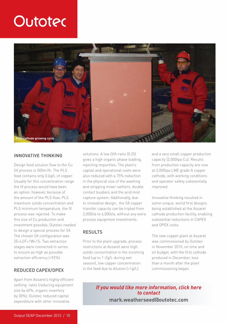
The new copper plant at Assarel was commissioned by Outotec in November 2010, on time and on budget, with the first cathode produced in December, less than a month after the plant commissioning began.
First cathode growing cycle
If you would like more information, click here to contact
Output SEAP December 2012 / 11
BUSINESS NEWS: BACKFILL SPECIALISTS ACQUISITION
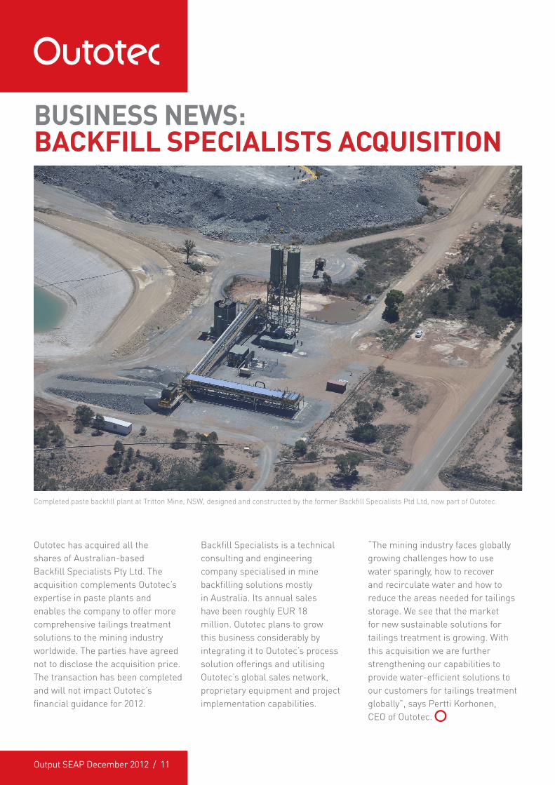
Outotec has acquired all the shares of Australian-based Backfill Specialists Pty Ltd. The acquisition complements Outotec’s expertise in paste plants and enables the company to offer more comprehensive tailings treatment solutions to the mining industry worldwide. The parties have agreed not to disclose the acquisition price. The transaction has been completed and will not impact Outotec’s financial guidance for 2012.
Backfill Specialists is a technical consulting and engineering company specialised in mine backfilling solutions mostly in Australia. Its annual sales have been roughly EUR 18 million. Outotec plans to grow this business considerably by integrating it to Outotec’s process solution offerings and utilising Outotec’s global sales network, proprietary equipment and project implementation capabilities.
Completed paste backfill plant at Tritton Mine, NSW, designed and constructed by the former Backfill Specialists Ptd Ltd, now part of Outotec.
“The mining industry faces globally growing challenges how to use water sparingly, how to recover and recirculate water and how to reduce the areas needed for tailings storage. We see that the market for new sustainable solutions for tailings treatment is growing. With this acquisition we are further strengthening our capabilities to provide water-efficient solutions to our customers for tailings treatment globally”, says Pertti Korhonen, CEO of Outotec.
Output SEAP December 2012 / 12
Author: Timo Juahiainen
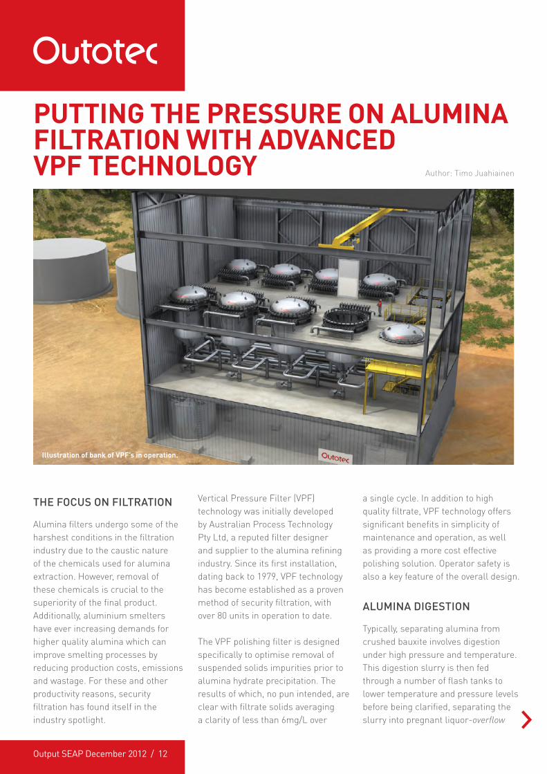
THE FOCUS ON FILTRATION
Alumina filters undergo some of the harshest conditions in the filtration industry due to the caustic nature of the chemicals used for alumina extraction. However, removal of these chemicals is crucial to the superiority of the final product. Additionally, aluminium smelters have ever increasing demands for higher quality alumina which can improve smelting processes by reducing production costs, emissions and wastage. For these and other productivity reasons, security filtration has found itself in the industry spotlight.
Vertical Pressure Filter (VPF) technology was initially developed by Australian Process Technology Pty Ltd, a reputed filter designer and supplier to the alumina refining industry. Since its first installation, dating back to 1979, VPF technology has become established as a proven method of security filtration, with over 80 units in operation to date.
The VPF polishing filter is designed specifically to optimise removal of suspended solids impurities prior to alumina hydrate precipitation. The results of which, no pun intended, are clear with filtrate solids averaging a clarity of less than 6mg/L over
PUTTING THE PRESSURE ON ALUMINA FILTRATION WITH ADVANCED VPF TECHNOLOGY
a single cycle. In addition to high quality filtrate, VPF technology offers significant benefits in simplicity of maintenance and operation, as well as providing a more cost effective polishing solution. Operator safety is also a key feature of the overall design.
ALUMINA DIGESTION
Typically, separating alumina from crushed bauxite involves digestion under high pressure and temperature. This digestion slurry is then fed through a number of flash tanks to lower temperature and pressure levels before being clarified, separating the slurry into pregnant liquor-overflow
Illustration of bank of VPF’s in operation.
Output SEAP December 2012 / 13
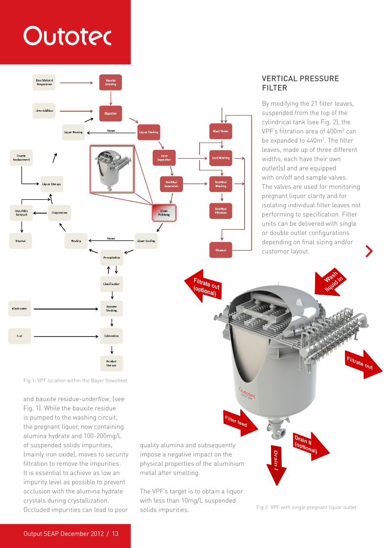
Fig.1: VPF location within the Bayer flowsheet
and bauxite residue-underflow, (see Fig. 1). While the bauxite residue is pumped to the washing circuit, the pregnant liquor, now containing alumina hydrate and 100-200mg/L of suspended solids impurities, (mainly iron oxide), moves to security filtration to remove the impurities. It is essential to achieve as low an impurity level as possible to prevent occlusion with the alumina hydrate crystals during crystallization. Occluded impurities can lead to poor
quality alumina and subsequently impose a negative impact on the physical properties of the aluminium metal after smelting.
The VPF’s target is to obtain a liquor with less than 10mg/L suspended solids impurities.
VERTICAL PRESSURE FILTER
By modifying the 21 filter leaves, suspended from the top of the cylindrical tank (see Fig. 2), the VPF’s filtration area of 400m2 can be expanded to 440m2. The filter leaves, made up of three different widths, each have their own outlet(s) and are equipped with on/off and sample valves. The valves are used for monitoring pregnant liquor clarity and for isolating individual filter leaves not performing to specification. Filter units can be delivered with single or double outlet configurations depending on final sizing and/or customer layout.
Fig.2: VPF with single pregnant liquor outlet
Output SEAP December 2012 / 14
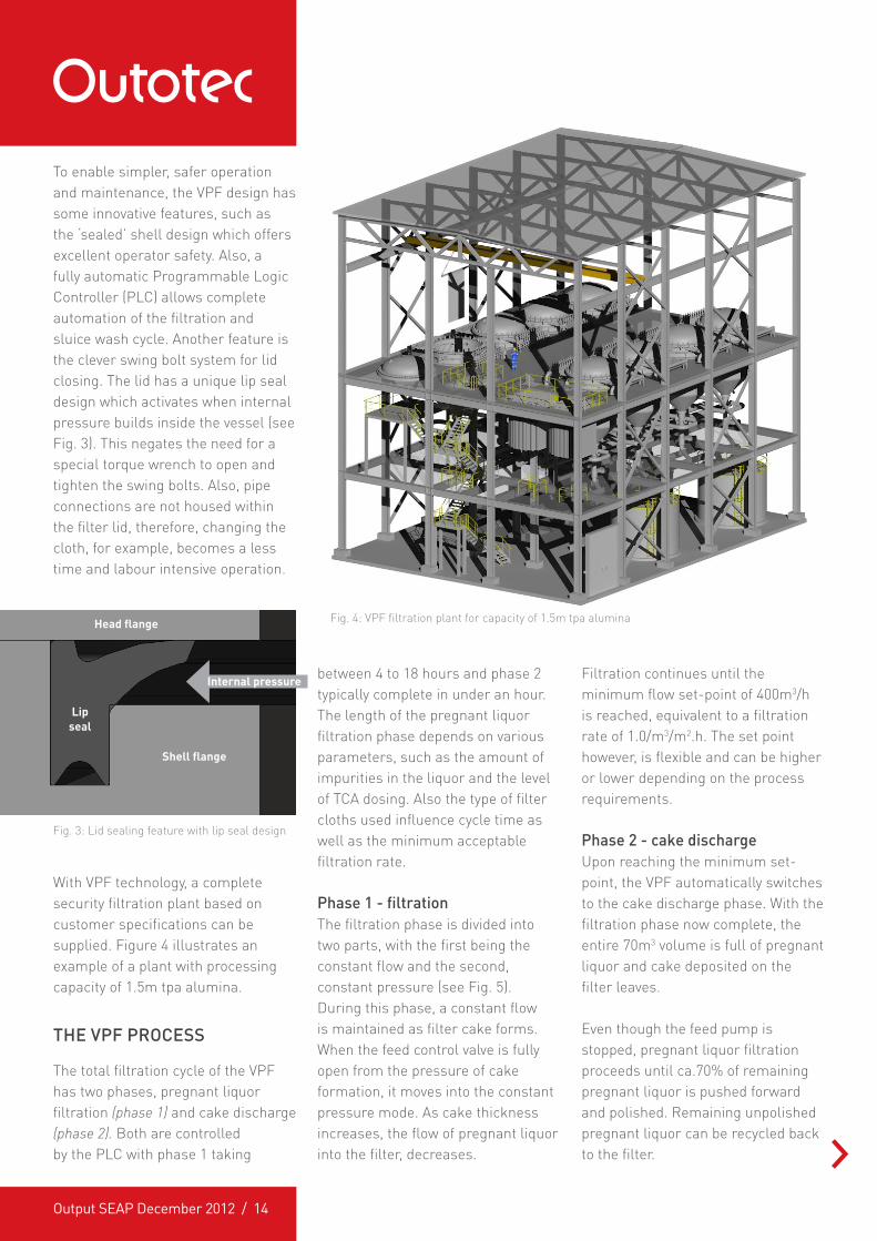
To enable simpler, safer operation and maintenance, the VPF design has some innovative features, such as the ‘sealed’ shell design which offers excellent operator safety. Also, a fully automatic Programmable Logic Controller (PLC) allows complete automation of the filtration and sluice wash cycle. Another feature is the clever swing bolt system for lid closing. The lid has a unique lip seal design which activates when internal pressure builds inside the vessel (see Fig. 3). This negates the need for a special torque wrench to open and tighten the swing bolts. Also, pipe connections are not housed within the filter lid, therefore, changing the cloth, for example, becomes a less time and labour intensive operation.
between 4 to 18 hours and phase 2 typically complete in under an hour. The length of the pregnant liquor filtration phase depends on various parameters, such as the amount of impurities in the liquor and the level of TCA dosing. Also the type of filter cloths used influence cycle time as well as the minimum acceptable filtration rate.
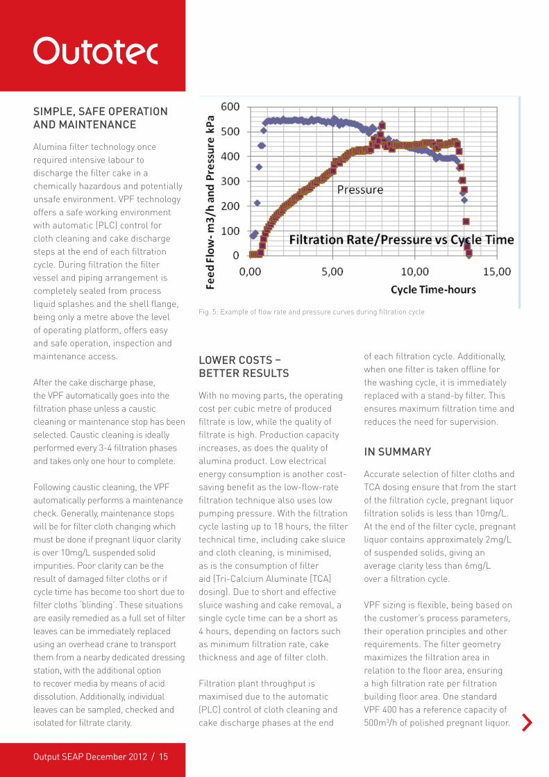
Phase 1 - filtrationThe filtration phase is divided into two parts, with the first being the constant flow and the second, constant pressure (see Fig. 5). During this phase, a constant flow is maintained as filter cake forms. When the feed control valve is fully open from the pressure of cake formation, it moves into the constant pressure mode. As cake thickness increases, the flow of pregnant liquor into the filter, decreases.
Filtration continues until the minimum flow set-point of 400m3/h is reached, equivalent to a filtration rate of 1.0/m3/m2.h. The set point however, is flexible and can be higher or lower depending on the process requirements.
Phase 2 - cake dischargeUpon reaching the minimum set-point, the VPF automatically switches to the cake discharge phase. With the filtration phase now complete, the entire 70m3 volume is full of pregnant liquor and cake deposited on the filter leaves.
Even though the feed pump is stopped, pregnant liquor filtration proceeds until ca.70% of remaining pregnant liquor is pushed forward and polished. Remaining unpolished pregnant liquor can be recycled back to the filter.
With VPF technology, a complete security filtration plant based on customer specifications can be supplied. Figure 4 illustrates an example of a plant with processing capacity of 1.5m tpa alumina.
THE VPF PROCESS
The total filtration cycle of the VPF has two phases, pregnant liquor filtration (phase 1) and cake discharge (phase 2). Both are controlled by the PLC with phase 1 taking
Fig. 4: VPF filtration plant for capacity of 1.5m tpa alumina
Lipseal
Head flange
Shell flange
Internal pressure
Fig. 3: Lid sealing feature with lip seal design
Output SEAP December 2012 / 15
SIMPLE, SAFE OPERATION AND MAINTENANCE
Alumina filter technology once required intensive labour to discharge the filter cake in a chemically hazardous and potentially unsafe environment. VPF technology offers a safe working environment with automatic (PLC) control for cloth cleaning and cake discharge steps at the end of each filtration cycle. During filtration the filter vessel and piping arrangement is completely sealed from process liquid splashes and the shell flange, being only a metre above the level of operating platform, offers easy and safe operation, inspection and maintenance access.
After the cake discharge phase, the VPF automatically goes into the filtration phase unless a caustic cleaning or maintenance stop has been selected. Caustic cleaning is ideally performed every 3-4 filtration phases and takes only one hour to complete.
Following caustic cleaning, the VPF automatically performs a maintenance check. Generally, maintenance stops will be for filter cloth changing which must be done if pregnant liquor clarity is over 10mg/L suspended solid impurities. Poor clarity can be the result of damaged filter cloths or if cycle time has become too short due to filter cloths ‘blinding’. These situations are easily remedied as a full set of filter leaves can be immediately replaced using an overhead crane to transport them from a nearby dedicated dressing station, with the additional option to recover media by means of acid dissolution. Additionally, individual leaves can be sampled, checked and isolated for filtrate clarity.
LOWER COSTS – BETTER RESULTS
With no moving parts, the operating cost per cubic metre of produced filtrate is low, while the quality of filtrate is high. Production capacity increases, as does the quality of alumina product. Low electrical energy consumption is another cost-saving benefit as the low-flow-rate filtration technique also uses low pumping pressure. With the filtration cycle lasting up to 18 hours, the filter technical time, including cake sluice and cloth cleaning, is minimised, as is the consumption of filter aid (Tri-Calcium Aluminate [TCA] dosing). Due to short and effective sluice washing and cake removal, a single cycle time can be a short as 4 hours, depending on factors such as minimum filtration rate, cake thickness and age of filter cloth.
Filtration plant throughput is maximised due to the automatic (PLC) control of cloth cleaning and cake discharge phases at the end
of each filtration cycle. Additionally, when one filter is taken offline for the washing cycle, it is immediately replaced with a stand-by filter. This ensures maximum filtration time and reduces the need for supervision.
IN SUMMARY
Accurate selection of filter cloths and TCA dosing ensure that from the start of the filtration cycle, pregnant liquor filtration solids is less than 10mg/L. At the end of the filter cycle, pregnant liquor contains approximately 2mg/L of suspended solids, giving an average clarity less than 6mg/L over a filtration cycle.
VPF sizing is flexible, being based on the customer’s process parameters, their operation principles and other requirements. The filter geometry maximizes the filtration area in relation to the floor area, ensuring a high filtration rate per filtration building floor area. One standard VPF 400 has a reference capacity of 500m3/h of polished pregnant liquor.
Fig. 5: Example of flow rate and pressure curves during filtration cycle
Output SEAP December 2012 / 16
About the authors...Timo Jauhiainen is Product Manager for the polishing filters product line. Timo originally worked for Larox Filters and following the acquisition of that business, went on to work for Outotec since 1998.
Low energy consumption, numerous cost-saving features and reliable, safe design are added value benefits to a polishing filter that also offers the lowest suspended solid impurities in pregnant liquor.
If you would like more information, click here to contact
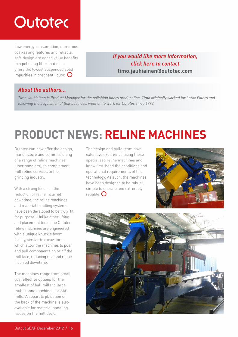
PRODUCT NEWS: RELINE MACHINESOutotec can now offer the design, manufacture and commissioning of a range of reline machines (liner handlers), to complement mill reline services to the grinding industry.
With a strong focus on the reduction of reline incurred downtime, the reline machines and material handling systems have been developed to be truly ‘fit for purpose’. Unlike other lifting and placement tools, the Outotec reline machines are engineered with a unique knuckle boom facility, similar to excavators, which allow the machines to push and pull components on or off the mill face, reducing risk and reline incurred downtime.
The machines range from small cost effective options for the smallest of ball mills to large multi-tonne machines for SAG mills. A separate jib option on the back of the machine is also available for material handling issues on the mill deck.
The design and build team have extensive experience using these specialised reline machines and know first-hand the conditions and operational requirements of this technology. As such, the machines have been designed to be robust, simple to operate and extremely reliable.