Embed Size (px)
Citation preview
High performance buildings in India are defined as buildings that have integrated bioclimatic
solar passive architectural design strategies and energy efficiency measures as recommended by
ECBC (Energy Conservation Building Code). The Energy Conservation Measures (ECMs) that
are under this case include ECM1 (Passive Solar design) and ECM4 (ECBC Compliant). The
technical information for all these ECMs is given as below.
Solar Passive design:
Over view of passive concepts:
Incorporation of solar passive techniques in a building
design helps to minimize load on conventional systems
such as heating, cooling, ventilation & light. Passive
strategies provide thermal and visual comfort by using
natural energy sources & sinks. Ex: solar radiation,
outside air, wet surfaces, vegetation etc means, in
composite climate: an architect‘s aim would be to design
a building in such a way that solar gains are maximized in
winter and, reduce solar gains in summer, and maximize
natural ventilation.
Once the solar passive architectural concepts are applied
to design, the load on conventional systems (HVAC &
lighting) is reduced. Architects can achieve a solar
passive design by studying the macro and micro climate
of the site, applying bioclimatic architecture design
features and taking advantage of the existing natural
resources on the site. The solar passive design strategy
should vary from one climate to another. Since these
buildings can also function independent of mechanical
systems, in case of power failure they are still well lit by
natural daylight and thermally comfortable.
The commonly considered low energy elements to achieve lower energy consumption in a
building are discussed below:
SOLAR PASSIVE DESIGN FEATURES
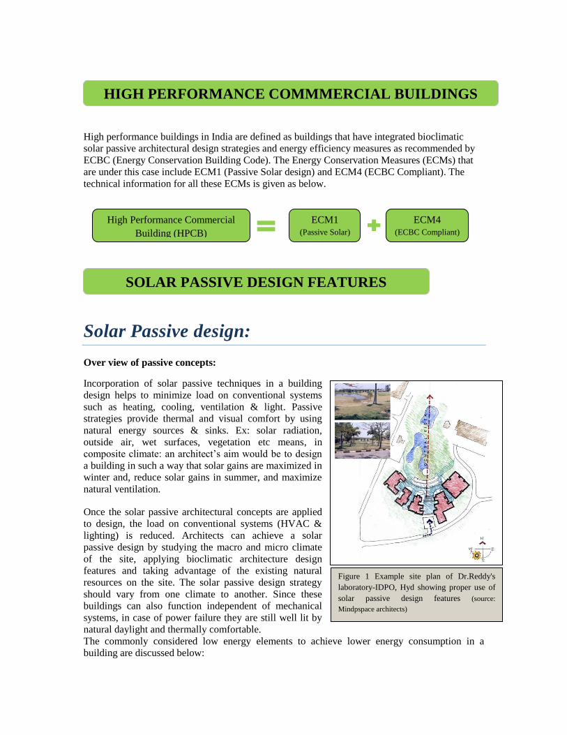
Figure 1 Example site plan of Dr.Reddy's
laboratory-IDPO, Hyd showing proper use of
solar passive design features (source:
Mindpspace architects)
HIGH PERFORMANCE COMMMERCIAL BUILDINGS
High Performance Commercial
Building (HPCB)
ECM1
(Passive Solar)
ECM4
(ECBC Compliant)

Landscape: Landscaping is an important element in altering the micro-climate of a place.
Proper landscaping reduced direct sun from striking and heating up building surfaces. It is the
best way to provide a buffer for heat, sun, noise, traffic, and airflow or for diverting airflow or
exchanging heat in a solar-passive design. It prevents reflected light carrying heat into a building
from the ground or other surfaces. Additionally, the shade created by trees, reduces air
temperature of the micro climate around the building through evapo-transpiration. Properly
designed roof gardens help to reduce heat loads in a building.
Figure 2: Location of landscape to cut direct sunlight
and shade buildings (source: www.oikos.com )
Planting deciduous trees on the southern side of a building is beneficial in a composite climate.
Deciduous plants such as mulberry or champa cut off direct sun during summer, and as these
trees shed leaves in winter, they allow the sun to heat the building in winter which is suitable in
composite climate.
Figure 3: Planting of deciduous trees to cut direct sunlight in summer, TERI Retreat Building
The use of dense trees and shrub plantings on the west and northwest sides of a building will
block the summer setting sun. Natural cooling without air-conditioning can be enhanced by
locating trees to channel south-easterly summer breezes in tropical climates like India. Cooling
breezes will be able to pass through the trunks of trees placed for shading. Shade can also be
created by using a combination of landscape features, such as shrubs and vines on arbours or
trellises. Trees, which serve as windbreaks or form shelterbelts, diminish wind. Certain climbers
are also useful for shading exposed walls from direct sunlight. Trees also provide visual relief and
a psychological barrier from traffic and thus reduce pollution on the site.
Location of Landscape to shade buildings
LANSCAPE
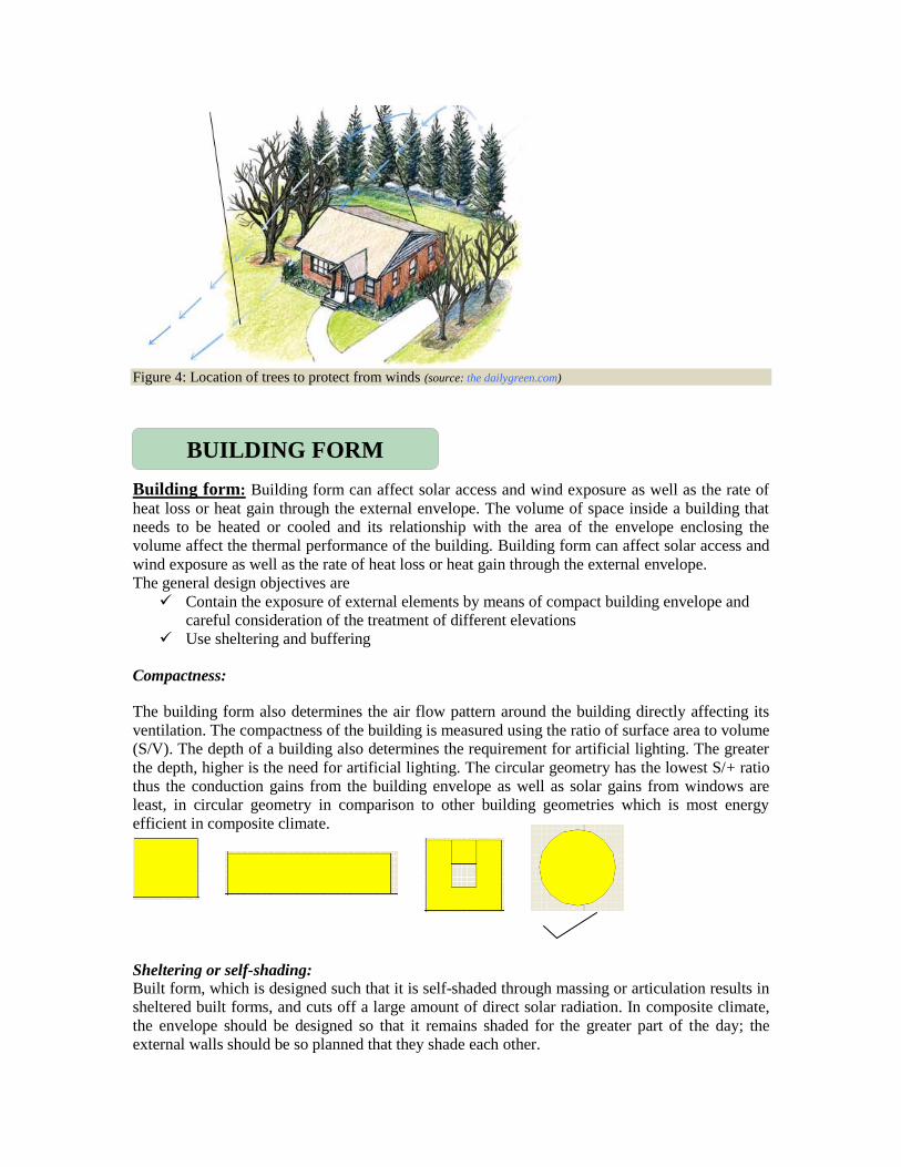
Figure 4: Location of trees to protect from winds (source: the dailygreen.com)
Building form: Building form can affect solar access and wind exposure as well as the rate of
heat loss or heat gain through the external envelope. The volume of space inside a building that
needs to be heated or cooled and its relationship with the area of the envelope enclosing the
volume affect the thermal performance of the building. Building form can affect solar access and
wind exposure as well as the rate of heat loss or heat gain through the external envelope.
The general design objectives are
Contain the exposure of external elements by means of compact building envelope and
careful consideration of the treatment of different elevations
Use sheltering and buffering
Compactness:
The building form also determines the air flow pattern around the building directly affecting its
ventilation. The compactness of the building is measured using the ratio of surface area to volume
(S/V). The depth of a building also determines the requirement for artificial lighting. The greater
the depth, higher is the need for artificial lighting. The circular geometry has the lowest S/+ ratio
thus the conduction gains from the building envelope as well as solar gains from windows are
least, in circular geometry in comparison to other building geometries which is most energy
efficient in composite climate.
Sheltering or self-shading:
Built form, which is designed such that it is self-shaded through massing or articulation results in
sheltered built forms, and cuts off a large amount of direct solar radiation. In composite climate,
the envelope should be designed so that it remains shaded for the greater part of the day; the
external walls should be so planned that they shade each other.
BUILDING FORM

Location of water bodies: Water is a good modifier of micro-climate. It takes up large amount
of heat in evaporation and causes significant cooling. Water has a moderating effect on the air
temperature of the micro climate. It possesses very high thermal storage capacity much higher
than the building materials like Brick, concrete, stone. Large bodies of water in the form of lake,
river, and fountain generally have a moderating effect on the temperature of the surrounding area
due to the higher thermal storage capacity of water compared to land and cause variations in
airflow. During the day the air is hotter over the land and rises, drawing cooler air in from the
water mass resulting in land breezes. During the night as the land mass cools quicker, the airflow
will be reversed. Water evaporation has a cooling effect in the surroundings. In humid climates,
water should be avoided as it adds humidity.
Figure 5 A view of the WALMI building in Bhopal which is in composite climate. The building form
overlooks a water body which has been designed to take advantage of modified micro climate (source: Energy
efficient buildings in India, TERI)
In solar passive design features, orientation is a major design consideration, mainly with regard to
solar radiation, daylight and wind.
In tropical climate like India long facades of buildings oriented towards North—South are
ORIENTATION
WATER BODIES
preferred. East and West receive maximum solar radiation during summer. In predominantly cold
regions, also North South long facades are advisable, as South orientation receives maximum
intensity of solar radiation in winter months.
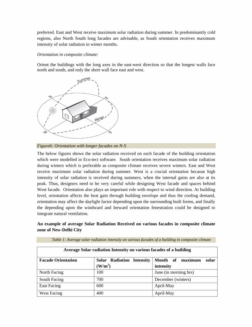
Orientation in composite climate:
Orient the buildings with the long axes in the east-west direction so that the longest walls face
north and south, and only the short wall face east and west.
Figure6: Orientation with longer facades on N-S
The below figures shows the solar radiation received on each facade of the building orientation
which were modelled in Eco-tect software. South orientation receives maximum solar radiation
during winters which is preferable as composite climate receives severe winters. East and West
receive maximum solar radiation during summer. West is a crucial orientation because high
intensity of solar radiation is received during summers, when the internal gains are also at its
peak. Thus, designers need to be very careful while designing West facade and spaces behind
West facade. Orientation also plays an important role with respect to wind direction. At building
level, orientation affects the heat gain through building envelope and thus the cooling demand,
orientation may affect the daylight factor depending upon the surrounding built forms, and finally
the depending upon the windward and leeward orientation fenestration could be designed to
integrate natural ventilation.
An example of average Solar Radiation Received on various facades in composite climate
zone of New-Delhi City
Table 1: Average solar radiation intensity on various facades of a building in composite climate
Average Solar radiation Intensity on various facades of a building
Facade Orientation Solar Radiation Intensity
(W/m2)
Month of maximum solar
intensity
North Facing 100 June (in morning hrs)
South Facing 700 December (winters)
East Facing 600 April-May
West Facing 400 April-May
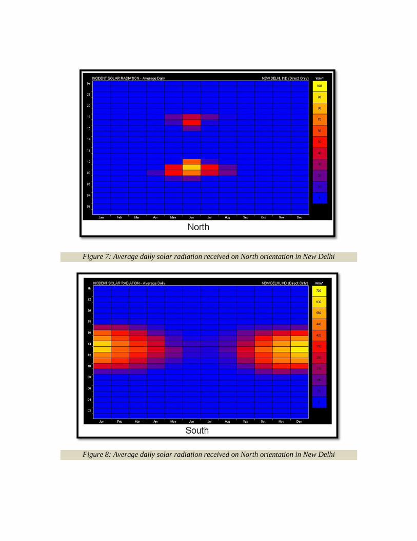
Figure 7: Average daily solar radiation received on North orientation in New Delhi
Figure 8: Average daily solar radiation received on North orientation in New Delhi
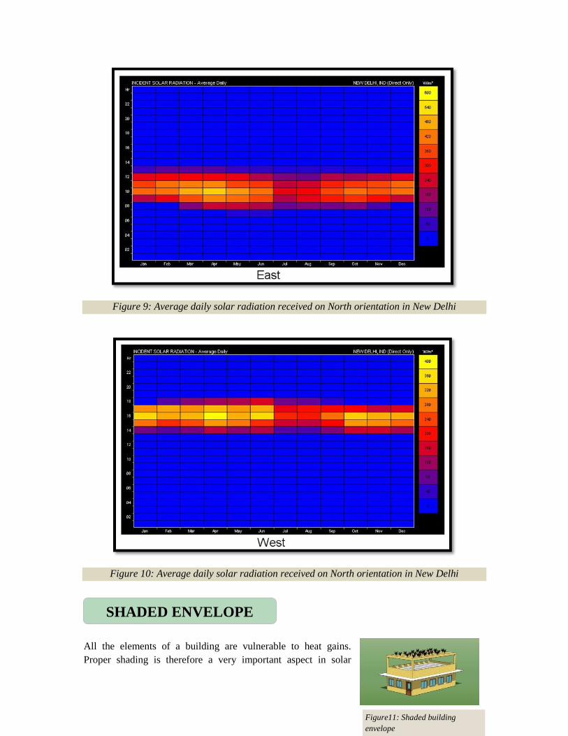
Figure 9: Average daily solar radiation received on North orientation in New Delhi
Figure 10: Average daily solar radiation received on North orientation in New Delhi
All the elements of a building are vulnerable to heat gains.
Proper shading is therefore a very important aspect in solar
SHADED ENVELOPE
Figure11: Shaded building
envelope
passive building design. It is observed using software simulations that, shading of roof, walls and
windows have considerable potential in reducing the cooling energy consumption. This section
explains the technical details and advantages of shaded envelope (Roof, Walls and Windows)
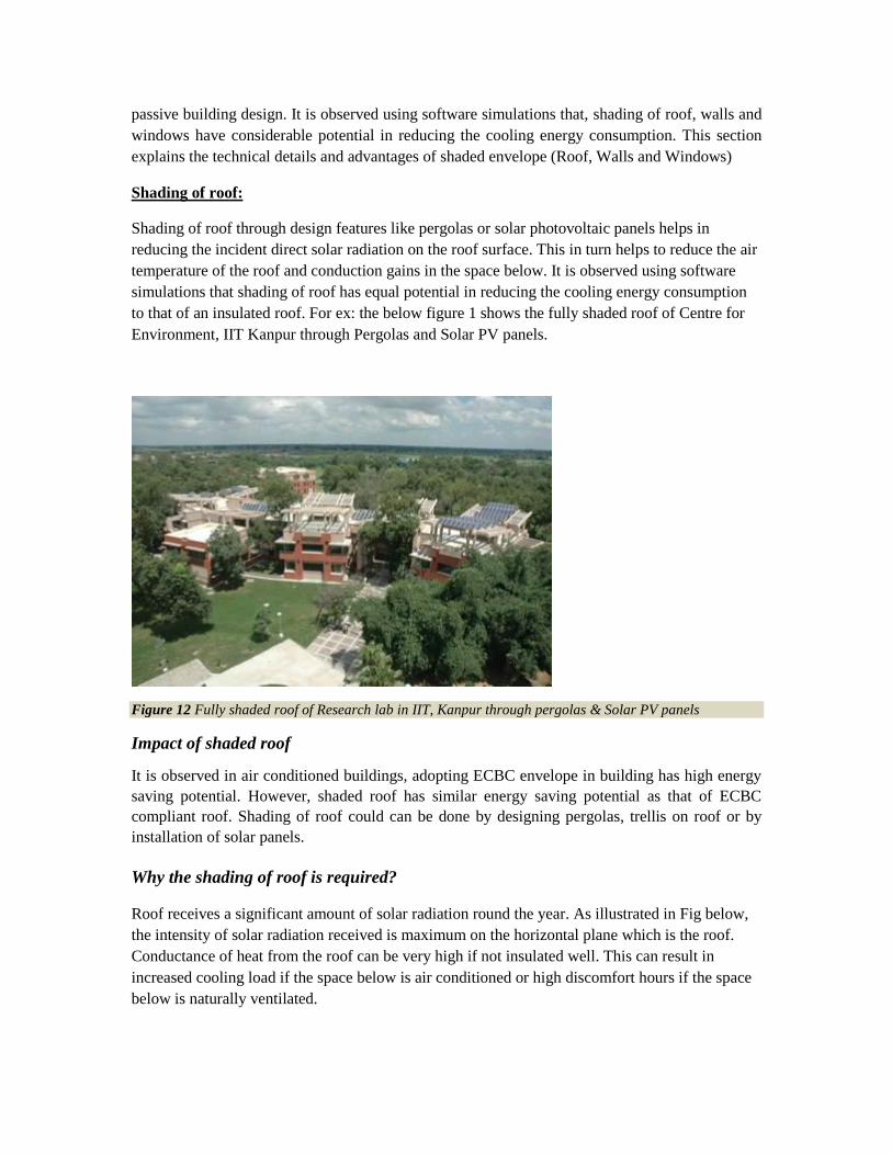
Shading of roof:
Shading of roof through design features like pergolas or solar photovoltaic panels helps in
reducing the incident direct solar radiation on the roof surface. This in turn helps to reduce the air
temperature of the roof and conduction gains in the space below. It is observed using software
simulations that shading of roof has equal potential in reducing the cooling energy consumption
to that of an insulated roof. For ex: the below figure 1 shows the fully shaded roof of Centre for
Environment, IIT Kanpur through Pergolas and Solar PV panels.
Figure 12 Fully shaded roof of Research lab in IIT, Kanpur through pergolas & Solar PV panels
Impact of shaded roof
It is observed in air conditioned buildings, adopting ECBC envelope in building has high energy
saving potential. However, shaded roof has similar energy saving potential as that of ECBC
compliant roof. Shading of roof could can be done by designing pergolas, trellis on roof or by
installation of solar panels.
Why the shading of roof is required?
Roof receives a significant amount of solar radiation round the year. As illustrated in Fig below,
the intensity of solar radiation received is maximum on the horizontal plane which is the roof.
Conductance of heat from the roof can be very high if not insulated well. This can result in
increased cooling load if the space below is air conditioned or high discomfort hours if the space
below is naturally ventilated.
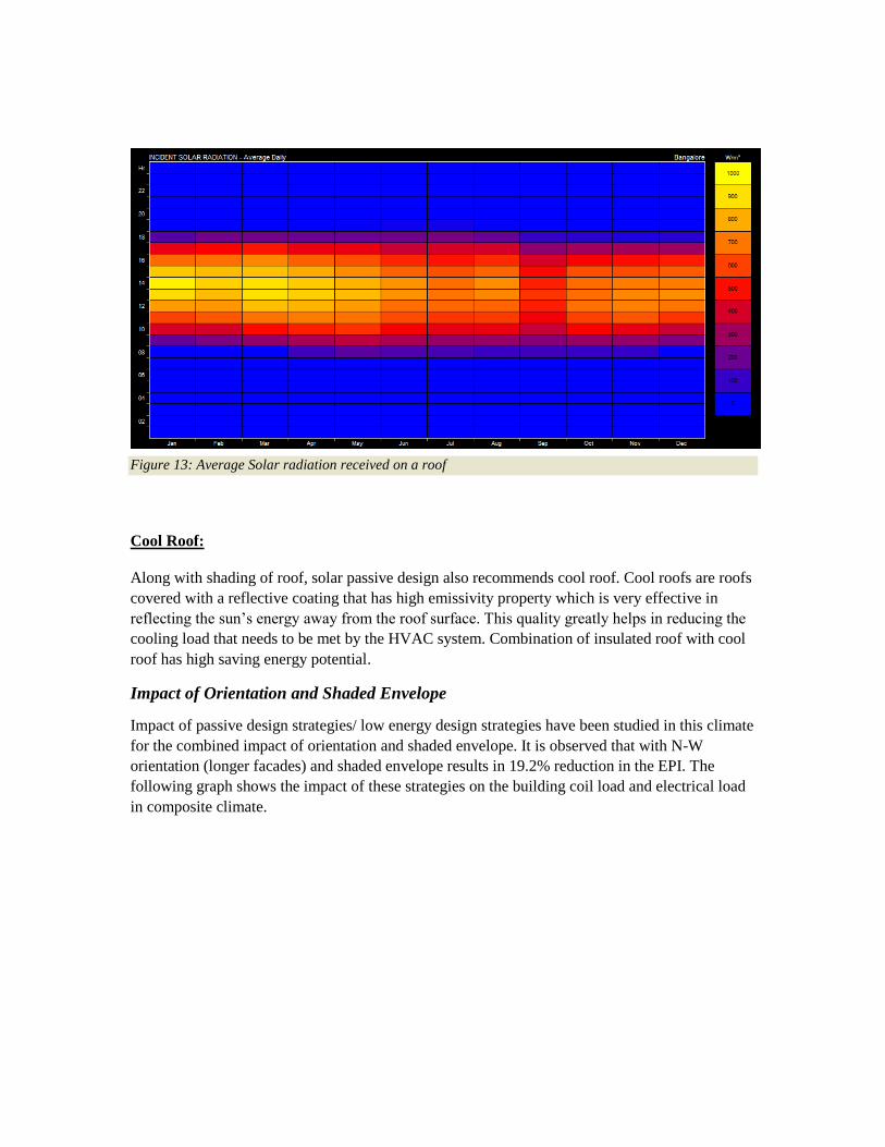
Figure 13: Average Solar radiation received on a roof
Cool Roof:
Along with shading of roof, solar passive design also recommends cool roof. Cool roofs are roofs
covered with a reflective coating that has high emissivity property which is very effective in
reflecting the sun‘s energy away from the roof surface. This quality greatly helps in reducing the
cooling load that needs to be met by the HVAC system. Combination of insulated roof with cool
roof has high saving energy potential.
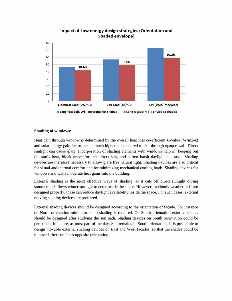
Impact of Orientation and Shaded Envelope
Impact of passive design strategies/ low energy design strategies have been studied in this climate
for the combined impact of orientation and shaded envelope. It is observed that with N-W
orientation (longer facades) and shaded envelope results in 19.2% reduction in the EPI. The
following graph shows the impact of these strategies on the building coil load and electrical load
in composite climate.
Shading of windows:
Heat gain through window is determined by the overall heat loss co-efficient U-value (W/m2-k)
and solar energy gain factor, and is much higher as compared to that through opaque wall. Direct
sunlight can cause glare. Incorporation of shading elements with windows help in: keeping out
the sun‘s heat, block uncomfortable direct sun, and soften harsh daylight contrasts. Shading
devices are therefore necessary to allow glare free natural light. Shading devices are also critical
for visual and thermal comfort and for minimizing mechanical cooling loads. Shading devices for
windows and walls moderate heat gains into the building.
External shading is the most effective ways of shading, as it cuts off direct sunlight during
summer and allows winter sunlight to enter inside the space. However, in cloudy weather or if not
designed properly, these can reduce daylight availability inside the space. For such cases, external
moving shading devices are preferred.
External shading devices should be designed according to the orientation of façade. For instance
on North orientation minimum or no shading is required. On South orientation external shades
should be designed after studying the sun path. Shading devices on South orientation could be
permanent in nature, as most part of the day, Sun remains in South orientation. It is preferable to
design movable external shading devices on East and West facades, so that the shades could be
removed after sun faces opposite orientation.

Figure 14 External shading for windows as an effective means of shading
For Non-conditioned buildings,
penetration of direct solar radiation
needs to be regulated.
The glazing system for windows in non-
conditioned spaces is usually single
glazed units with clear glass as the
windows will be opened to allow ventilation. However to
avoid heat entering from direct solar radiation through the
openings, external shading devices play an important role.
In the non-conditioned buildings thus shading device plays
a crucial role in the thermal performance of a window.
Windows on facades, facing different cardinal directions,
should be provided by the shading devices which can cut
the direct incident solar radiation for the critical solar
angles.
Horizontal Sun Angle (HSA)
This is the horizontal angle between the normal of the window and the Sun azimuth angle at a
given time as shown in the figure 14.
The horizontal sun angle at critical hours can be cut by the vertical fins provided as external
shading device.
Figure 15 Details of HSA & VSA

Figure 16 Horizontal fins as an external shading
device
Vertical Solar Angle (VSA)
It is the angle that a plane containing the bottom two points of the window and the centre of the
Sun makes with the ground when measured normal to the shaded surface as shown in the figure
14.
The vertical solar angle at critical hours can be cut by the horizontal fins provided as external
shading device.
The critical Horizontal Solar Angle (HSA) and Vertical Solar Angle (VSA) for fenestrations
located on the cardinal directions (as shown in the figure) given below in the table should be cut
down by designing appropriate shading devices in the composite climate –
Table 2: Example of Solar angles to be cut on various cardinal directions in composite climate building
Solar Angles to be cut on various cardinal directions
Cardinal Directions HSA (Horizontal Solar Angle)
in Degrees
VSA (Vertical Solar
Angle) in Degree
North - -
East - 44.1
West - 54.8
South -14.8 65.5
North-East (NE) 39.4 51.3
North-West (NW) -44.6 63.4
South-East (SE) -50.6 56.7
South-West (SW) 45.4 63.7
Note –
Angles have been measured from the normal to the fenestration
Angles measured anti-clockwise from the normal to the fenestration have been shown with negative sign for HSA (horizontal solar angle)

Figure 17 Horizontal & vertical fins as an external shading device
Figure 16: Window Shading Design
Example to design a shading device for a window:
For a window of height 1.5 m and width 3m, design shading device to cut the HSA of 450 and
VSA of 600.
Design of shading device to cut the VSA
The vertical solar angle of 600 can be cut by providing a single
horizontal overhang of length 841mm or it can be cut by providing
two horizontal projections each of length 408mm placed at a
distance of 750mm as shown in the figure.
The length and spacing can be calculated either by the drafting
softwares like auto-cad, sketchup etc. by graphical method or it can
be manually calculated by the mathematical formula given below –
Depth of shading device = Spacing between the shading device x
{tan (90 -VSA)}
For a given VSA either of the values for Depth or Spacing between
shading overhangs can be selected to get the value of other
one.
Design of shading device to cut the HSA
Figure 18 Design of a shading
device to cut VSA

The horizontal solar angle of 450 can be cut by providing a single vertical fin of length 2907mm
or it can be cut by providing four vertical fins each of length 657mm placed at a distance of
657mm as shown in the figure.
The length and spacing can be calculated either by the drafting softwares like auto-cad, sketchup
etc. by graphical method or it can be manually calculated by the mathematical formula given
below –
Depth of vertical fins = Spacing between the vertical fins x
{tan (90 -HSA)}
For a given HSA either of the values for Depth or
Spacing between vertical fins can be selected to get
the value of other one.
It is always desirable to break single overhang with
larger depth into multiple overhangs of smaller
length. It enhances the amount of daylight
penetration in the space. The figure in right shows
the comparison between amount of daylight
penetration for two shading devices, one with single
deep overhang and the other with multiple smaller
overhangs.
Shading devices for windows are of various types (Bansal, Hauser, and Minke, 1994) like:
• Moveable opaque (roller blind, curtains etc) can be highly effective in reducing solar gains
but eliminate view & impede air movement
• Louvres (Adjustable or fixed) affect the view and air movement to some degree
• Fixed overhangs
Fixed louvers:
They can be designed as fixed and can be cost effective and can become an integral part of the
building aesthetic but does not cope with changing altitude of sun.
Summers can be exceedingly hot in composite climate; consequently from an early date, openings
in buildings were partially closed by means of open-work coverings made from stone, stucco,
ceramic or wood. These coverings reduce the heat gain to the building and also add aesthetic
value to the building.
Figure 20 Comparison of daylight penetratio
between multiple overhangs and single overhang
(source: www.whygreenbuildings.com )
Figure 19 Design of a shading
device to cut HSA
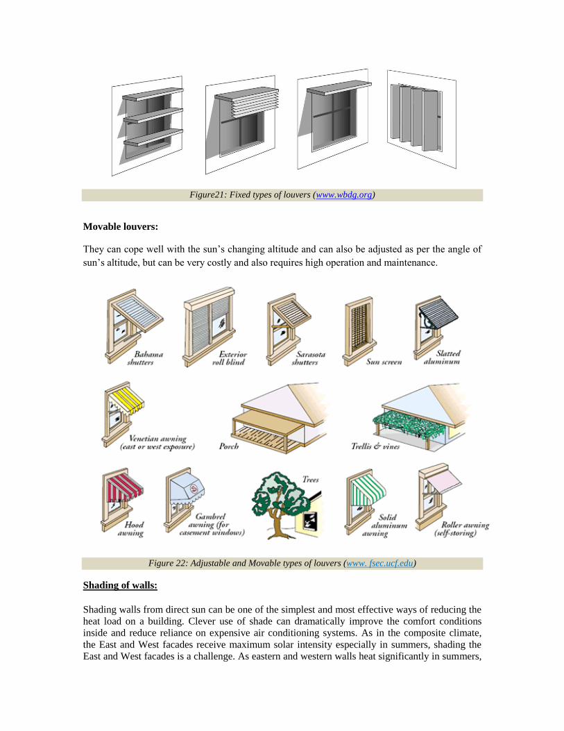
Figure21: Fixed types of louvers (www.wbdg.org)
Movable louvers:
They can cope well with the sun‘s changing altitude and can also be adjusted as per the angle of
sun‘s altitude, but can be very costly and also requires high operation and maintenance.
Figure 22: Adjustable and Movable types of louvers (www. fsec.ucf.edu)
Shading of walls:
Shading walls from direct sun can be one of the simplest and most effective ways of reducing the
heat load on a building. Clever use of shade can dramatically improve the comfort conditions
inside and reduce reliance on expensive air conditioning systems. As in the composite climate,
the East and West facades receive maximum solar intensity especially in summers, shading the
East and West facades is a challenge. As eastern and western walls heat significantly in summers,
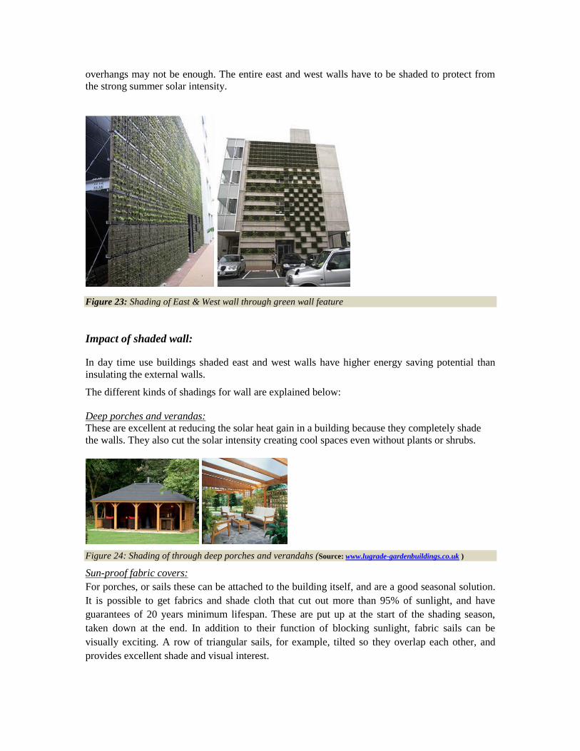
overhangs may not be enough. The entire east and west walls have to be shaded to protect from
the strong summer solar intensity.
Figure 23: Shading of East & West wall through green wall feature
Impact of shaded wall:
In day time use buildings shaded east and west walls have higher energy saving potential than
insulating the external walls.
The different kinds of shadings for wall are explained below:
Deep porches and verandas:
These are excellent at reducing the solar heat gain in a building because they completely shade
the walls. They also cut the solar intensity creating cool spaces even without plants or shrubs.
Figure 24: Shading of through deep porches and verandahs (Source: www.lugrade-gardenbuildings.co.uk )
Sun-proof fabric covers:
For porches, or sails these can be attached to the building itself, and are a good seasonal solution.
It is possible to get fabrics and shade cloth that cut out more than 95% of sunlight, and have
guarantees of 20 years minimum lifespan. These are put up at the start of the shading season,
taken down at the end. In addition to their function of blocking sunlight, fabric sails can be
visually exciting. A row of triangular sails, for example, tilted so they overlap each other, and
provides excellent shade and visual interest.

Figure 26: Plant vines on
outside of east & west walls
or to the porch reduces high
solar heat gains
Figure 27: Solar PV panels as
shading modules for the walls
(Source: www.sunenergysite.eu )
Figure 28: Series of louvers as a
wall shading device
(Source: www.fsec.ucf.edu )
Figure 25: Shading through sun proof fabric and verandahs (Source: www.infolink.com )
Vertical shading:
Vertical shading is the most advisable form of shading to cut the intensive solar heat gains for
east and west walls especially in summer. It is some form of vertical light blocker that is placed at
the external edge of the overhang or porch roof, extending all the way to the ground.
It can be movable louvers, jalis, panels of trellis, lath or shade cloth or it can be climbing plants
trained to grow up supports, either deciduous or rapidly growing annual vines. Plants have an
additional cooling advantage: as well as blocking light, they evaporate cool air passing through
their leaves. Jalis act as cost effective treatments for shading both for windows and walls. They
bring coolness due to the breezes blowing through the jalis that fill walls. Gaps between the jalis
let air and sunlight through a wall, while diffusing the glare of sunlight and cutting the intense
heat. They also act as elements for enhancing and beautifying the architecture of the building.
The modern form of shading is solar PV shading. In this, the solar energy can be used
simultaneously shading the building. Vertical shading has the advantage that is can be placed
close to a wall, so is especially useful where deep porches are not wanted and/or not possible due
to lack of space.

Figure 29: Brick jails as shading devices and aesthetic
architectural elements (Source: www.gharexpert.com)
Figure 30: Panel of trellis as shading devices (Source: www.archdigm.com)
Figure 31: Fixed types of jalis for shading (www.wikipedia.org)
Day lighting has a major effect on the appearance of space and can have considerable
implications on energy efficiency, if used properly. Its variability is subtly pleasing to the
occupant in contrast to the relatively monotonous environment produced by artificial light. It
helps to create optimum working conditions by bringing out the natural contrast and colour of
objects. The presence of natural light can bring a sense of well being and awareness of the wider
environment. Day lighting is important particularly in commercial and other non-domestic
buildings that function during the day. Integration of day lighting with artificial light brings about
considerable savings in energy consumption. A good day lighting system, has number of
DAYLIGHT INTEGRATION
elements most of which must be incorporated into the building design at an early stage. This can
be achieved by considering the following relation to the incidence of day light on the building.
• Orientation, space organization and geometry of the space to be lit
• Location, form & dimension of the fenestrations through which day light will enter
• Location & surface properties of internal partitions that affect the day light distribution by
reflection
• Location, form and dimensions of shading devices that provides protection from excessive light
and glare
• Light and thermal characteristics of the glazing materials
Tangible benefits of Natural day lighting integration:
Live case study;
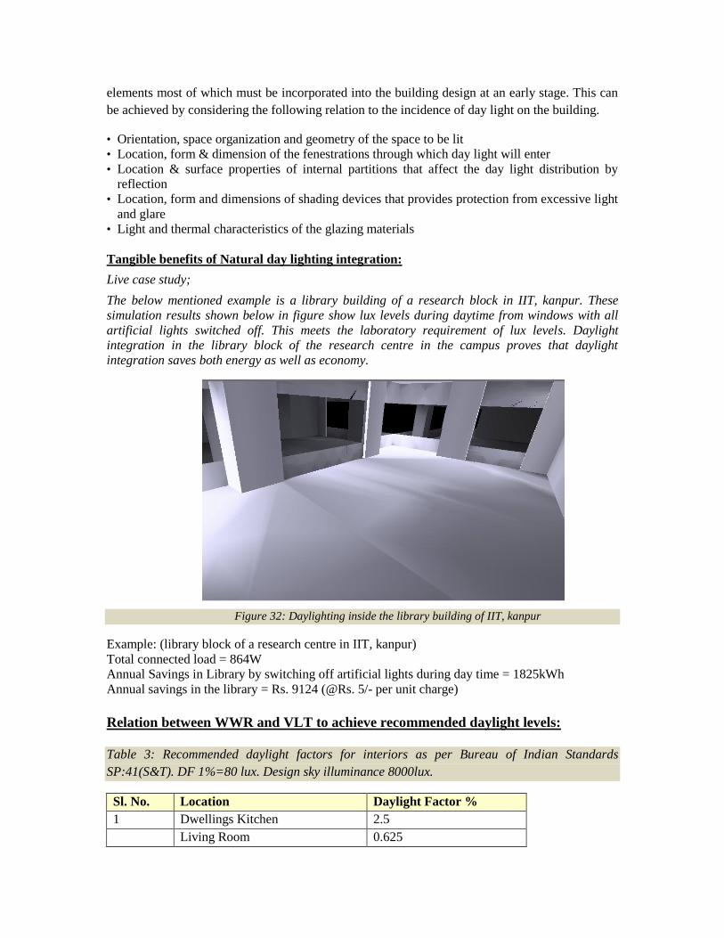
The below mentioned example is a library building of a research block in IIT, kanpur. These
simulation results shown below in figure show lux levels during daytime from windows with all
artificial lights switched off. This meets the laboratory requirement of lux levels. Daylight
integration in the library block of the research centre in the campus proves that daylight
integration saves both energy as well as economy.
Figure 32: Daylighting inside the library building of IIT, kanpur
Example: (library block of a research centre in IIT, kanpur)
Total connected load = 864W
Annual Savings in Library by switching off artificial lights during day time = 1825kWh
Annual savings in the library = Rs. 9124 (@Rs. 5/- per unit charge)
Relation between WWR and VLT to achieve recommended daylight levels:
Table 3: Recommended daylight factors for interiors as per Bureau of Indian Standards
SP:41(S&T). DF 1%=80 lux. Design sky illuminance 8000lux.
Sl. No. Location Daylight Factor %
1 Dwellings Kitchen 2.5
Living Room 0.625

Study room 1.9
Circulation 0.313
2 Schools
Class room desk top, black board 1.9—-3.8
Laboratory 2.5—3.8
3 Offices/commercial spaces
General 1.9
Drawing, typing 3.75
Enquiry 0.625—1.9
4 Hospitals
General wards 1.25
Pathological laboratory 2.5-3.75
5 Libraries
Stack room 0.9—1.9
Reading room 1.9-3.75
Counter area 2.5—-3.75
Catalogue room 1.9—2.5
As per BIS, the recommended daylight level for an office space, in the centre of the room should
be 150lux. To achieve, the above BIS recommended daylight levels in a commercial building
(table 1), window optimisation analysis had been carried out by using simulations for various
WWR ranging from 10% to 100% and VLT values of glass ranging from 10% to 90% in the
project ― High performance commercial buildings in India‖. Lighting levels were calculated to
identify what % of WWR and VLT in combination achieves the daylight levels recommended by
BIS and to find out the optimum WWR. From the analysis the following Table is obtained which
shows the relation between WWR and VLT to achieve the BIS recommended daylight levels. The
following table also helps in selecting the optimum WWR with corresponding VLT of glass to
meet the recommended daylight levels in a working space.
Daylight Factors at the Centre of the day lit zone
Visual Light
Transmittance
of Glass (%)
DF for
WWR
10%
DF for
WWR
20%
DF for
WWR
30%
DF for
WWR
40%
DF for
WWR
50%
DF for
WWR
60%
DF for
WWR
70%
DF for
WWR
80%
DF for
WWR
90%
DF
for
WWR
100%
10 0.3 0.5 0.6 0.7 0.8 0.8 0.9 0.9 0.9 0.9
20 0.6 1.0 1.2 1.4 1.5 1.7 1.7 1.8 1.8 1.9
30 1.0 1.6 1.8 2.1 2.3 2.5 2.6 2.7 2.7 2.8
40 1.2 2.1 2.4 2.8 3.1 3.3 3.4 3.6 3.6 3.7
50 1.5 2.6 3.1 3.5 3.8 4.1 4.3 4.5 4.5 4.6
60 1.9 3.1 3.7 4.2 4.5 5.0 5.2 5.4 5.4 5.6
Table 4: Relation between WWR and VLT to achieve recommended daylight levels
The highlighted are the cases for each WWR for which the minimum corresponding VLT
of glass is required to meet the recommended day light factor in an office space. It was
observed that minimum 10% WWR & 60% VLT of the glass is required to achieve
the recommended illumination and daylight factor at the centre of the day lit zone in
an office building. Similarly 40% VLT is required for WWR 20% and 30% to meet
the required day lit levels. For WWR ranging from 40-90% minimum VLT
required is 30% to achieve the day lit levels.
Surface Reflectance: For daylight integration, the desirable internal and external finish of the
building should be light in colour, as light colored surfaces will reflect more daylight than dark
surfaces. Desirable reflectance inside a room and common finishes to achieve them are provided
in table below.
Table 5: Desirable reflectance levels in a room
Surface Desirable reflectance Typical finish to achieve reflectance
Ceiling 0.7—0.8 White colour
Wall 0.5—0.6 Cream, light green
Table top 0.35-0.5 Brick colour
Floor 0.15-0.3 Medium Grey
Innovative Day lighting systems:
Day lighting systems help in better daylight integration in the buildings. There are
various day lighting systems. Some of them are as explained below:
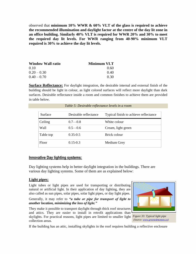
Light pipes:
Light tubes or light pipes are used for transporting or distributing
natural or artificial light. In their application of day lighting, they are
also called as sun pipes, solar pipes, solar light pipes, or day light pipes.
Generally, it may refer to “a tube or pipe for transport of light to
another location, minimizing the loss of light.”
They make it possible to transport daylight through thick roof structures
and attics. They are easier to install in retrofit applications than
skylights. For practical reasons, light pipes are limited to smaller light
collection areas.
If the building has an attic, installing skylights in the roof requires building a reflective enclosure
Window Wall ratio Minimum VLT
0.10 0.60
0.20 – 0.30 0.40
0.40 – 0.70 0.30
Figure 33: Typical light pipe
(Source: www.greenedmonton.ca)
to pass the light through the attic. Unless the attic is empty, this may be difficult. Light pipes are
easier to pass through attics. In effect, a light pipe is a small skylight with an integral reflective
enclosure.
The light pipe has to be made of a solid transparent material, such as glass or plastic.
The light pipe can be long, and it can have any number of bends.
To make economical, all the light has to be squeezed in to a light piece of small diameter.
A small conduit is desirable to minimise heat loss and to make the light pipe easy to
install.
There are 2 types of light pipes:
1. Simple light pipes: (rigid wall light pipe & flexible wall light pipe as shown in figures below)
2. Sun trackers
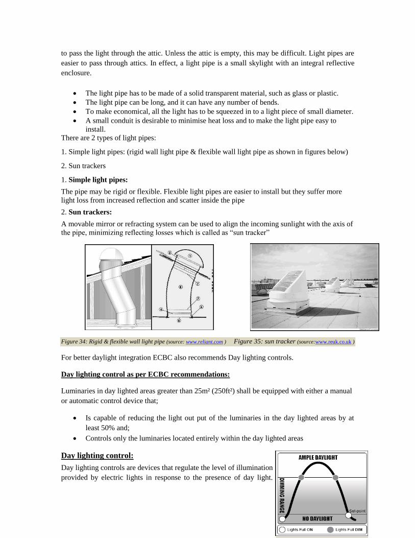
1. Simple light pipes:
The pipe may be rigid or flexible. Flexible light pipes are easier to install but they suffer more
light loss from increased reflection and scatter inside the pipe
2. Sun trackers:
A movable mirror or refracting system can be used to align the incoming sunlight with the axis of
the pipe, minimizing reflecting losses which is called as ―sun tracker‖
Figure 34: Rigid & flexible wall light pipe (source: www.reliant.com ) Figure 35: sun tracker (source:www.reuk.co.uk )
For better daylight integration ECBC also recommends Day lighting controls.
Day lighting control as per ECBC recommendations:
Luminaries in day lighted areas greater than 25m² (250ft²) shall be equipped with either a manual
or automatic control device that;
Is capable of reducing the light out put of the luminaries in the day lighted areas by at
least 50% and;
Controls only the luminaries located entirely within the day lighted areas
Day lighting control:
Day lighting controls are devices that regulate the level of illumination
provided by electric lights in response to the presence of day light.
Figure 36: Daylight control
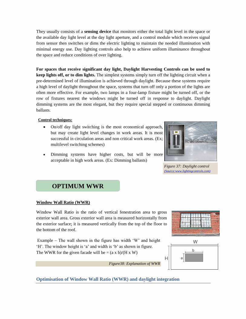
They usually consists of a sensing device that monitors either the total light level in the space or
the available day light level at the day light aperture, and a control module which receives signal
from sensor then switches or dims the electric lighting to maintain the needed illumination with
minimal energy use. Day lighting controls also help to achieve uniform illuminance throughout
the space and reduce conditions of over lighting.
For spaces that receive significant day light, Daylight Harvesting Controls can be used to
keep lights off, or to dim lights. The simplest systems simply turn off the lighting circuit when a
pre-determined level of illumination is achieved through daylight. Because these systems require
a high level of daylight throughout the space, systems that turn off only a portion of the lights are
often more effective. For example, two lamps in a four-lamp fixture might be turned off, or the
row of fixtures nearest the windows might be turned off in response to daylight. Daylight
dimming systems are the most elegant, but they require special stepped or continuous dimming
ballasts.
Control techniques:
On/off day light switching is the most economical approach,
but may create light level changes in work areas. It is most
successful in circulation areas and non critical work areas. (Ex;
multilevel switching schemes)
Dimming systems have higher costs, but will be more
acceptable in high work areas. (Ex: Dimming ballasts)
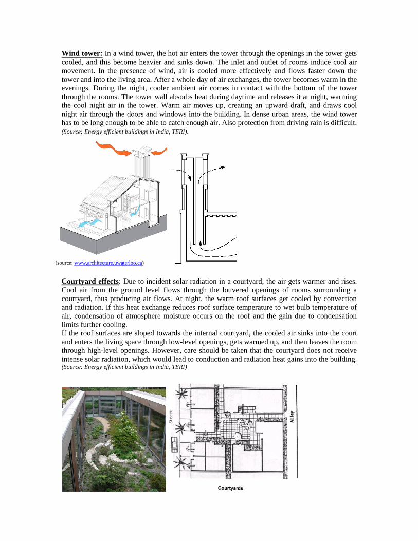
Window Wall Ratio (WWR)
Window Wall Ratio is the ratio of vertical fenestration area to gross
exterior wall area. Gross exterior wall area is measured horizontally from
the exterior surface; it is measured vertically from the top of the floor to
the bottom of the roof.
Example – The wall shown in the figure has width ‗W‘ and height
‗H‘. The window height is ‗a‘ and width is ‗b‘ as shown in figure.
The WWR for the given facade will be = (a x b)/(H x W)
Figure38: Explanation of WWR
Optimisation of Window Wall Ratio (WWR) and daylight integration
OPTIMUM WWR
Figure 37: Daylight control
(Source:www.lightingcontrols.com)

Analysis using simulation engines was carried out in this project ―High Performance Commercial
buildings in India‖ to observe the impact of various WWR on the cooling energy demand. As
expected the cooling energy demand increases with increase in window wall ratio. Therefore
ECBC has made glass selection more stringent with higher WWR. The figure below shows a
reduction in cooling energy consumption for higher WWR, if a higher performance glass with
higher WWR is used.
E nerg y us e in B as e c as e & E C B C env elope c as e
1,150,000
1,200,000
1,250,000
1,300,000
1,350,000
1,400,000
10 20 30 40 50 60
WWR
En
erg
y u
se
(k
Wh
)
B as e cas e E C B C E nvelope
E nerg y us e in B as e c as e & E C B C env elope c as e
1,150,000
1,200,000
1,250,000
1,300,000
1,350,000
1,400,000
10 20 30 40 50 60
WWR
En
erg
y u
se
(k
Wh
)
B as e cas e E C B C E nvelope
Figure 39: Energy Consumption with out Daylight Integration
On comparing the annual energy consumption of a building with various Window Wall Ratios it
is observed in the graph above that the lowest energy consumption is in the case of WWR 10%.
Window Wall Ratio however is not optimised if daylight integration is not carried out. Optimum
Window Wall Ratio would achieve a balance between cooling energy demand and lighting
energy demand due to integration of natural daylight. On integration of daylight in the office floor
space the following graph is obtained. In the graph below it is observed that minimum electricity
consumption is in the case where WWR is in the range of 20-30%. This is due to reduced
artificial lighting demand which would also have an impact on cooling energy demand. It should
be observed that after integrating daylight, on comparing annual electricity consumption, WWR
with 10% has higher electricity consumption due to increased consumption by artificial lighting.
Therefore the optimum WWR recommended is 20-30% with daylight integration.

E nerg y us e in B as e c as e and E C B C c as e +daylig ht
integ ration
950,000
1,000,000
1,050,0001,100,000
1,150,000
1,200,000
1,250,0001,300,000
1,350,000
1,400,000
10 20 30 40 50 60
WWR
En
erg
y u
se
(k
Wh
)
B as e cas e E C B C envelope+ daylight integration
E nerg y us e in B as e c as e and E C B C c as e +daylig ht
integ ration
950,000
1,000,000
1,050,0001,100,000
1,150,000
1,200,000
1,250,0001,300,000
1,350,000
1,400,000
10 20 30 40 50 60
WWR
En
erg
y u
se
(k
Wh
)
B as e cas e E C B C envelope+ daylight integration
Figure 40: Energy Consumption comparison with Daylight Integration
Passive cooling systems rely on natural heat-sinks to remove heat from the building. They derive
cooling directly from evaporation, convection, and radiation without using any intermediate
electrical devices. All passive cooling strategies rely on daily changes in temperature and relative
humidity. The applicability of each system depends on the climatic conditions. The relatively
simple techniques that can be adopted to provide natural cooling in the building through solar
passive design strategies have been explained earlier. This section briefly describes the various
passive techniques that aim heat loss from the building by convection, radiation and evaporation,
or by using storage capacity of surrounding, eg: earth berming
Ventilation: Good natural ventilation requires locating openings in opposite pressure zones.
Natural ventilation can also be enhanced through tall spaces like stacks, chimneys etc in a
building. With openings near the top of stacks warm air can escape where as cooler air enters the
building from openings near the ground. (Source: Energy efficient buildings in India, TERI).
source: www.sacsustainable.com
ADVANCED PASSIVE COOLING
STRATEGIES
Wind tower: In a wind tower, the hot air enters the tower through the openings in the tower gets
cooled, and this become heavier and sinks down. The inlet and outlet of rooms induce cool air
movement. In the presence of wind, air is cooled more effectively and flows faster down the
tower and into the living area. After a whole day of air exchanges, the tower becomes warm in the
evenings. During the night, cooler ambient air comes in contact with the bottom of the tower
through the rooms. The tower wall absorbs heat during daytime and releases it at night, warming
the cool night air in the tower. Warm air moves up, creating an upward draft, and draws cool
night air through the doors and windows into the building. In dense urban areas, the wind tower
has to be long enough to be able to catch enough air. Also protection from driving rain is difficult.
(Source: Energy efficient buildings in India, TERI).
(source: www.architecture.uwaterloo.ca)
Courtyard effects: Due to incident solar radiation in a courtyard, the air gets warmer and rises.
Cool air from the ground level flows through the louvered openings of rooms surrounding a
courtyard, thus producing air flows. At night, the warm roof surfaces get cooled by convection
and radiation. If this heat exchange reduces roof surface temperature to wet bulb temperature of
air, condensation of atmosphere moisture occurs on the roof and the gain due to condensation
limits further cooling.
If the roof surfaces are sloped towards the internal courtyard, the cooled air sinks into the court
and enters the living space through low-level openings, gets warmed up, and then leaves the room
through high-level openings. However, care should be taken that the courtyard does not receive
intense solar radiation, which would lead to conduction and radiation heat gains into the building. (Source: Energy efficient buildings in India, TERI)
(Source: www.gnla.ca ) (Source: www.ci.erdlands.ca.us)
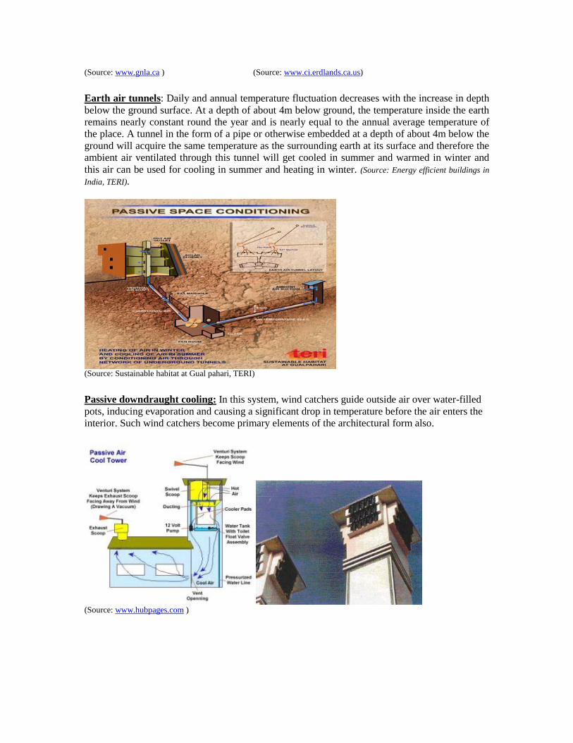
Earth air tunnels: Daily and annual temperature fluctuation decreases with the increase in depth
below the ground surface. At a depth of about 4m below ground, the temperature inside the earth
remains nearly constant round the year and is nearly equal to the annual average temperature of
the place. A tunnel in the form of a pipe or otherwise embedded at a depth of about 4m below the
ground will acquire the same temperature as the surrounding earth at its surface and therefore the
ambient air ventilated through this tunnel will get cooled in summer and warmed in winter and
this air can be used for cooling in summer and heating in winter. (Source: Energy efficient buildings in
India, TERI).
(Source: Sustainable habitat at Gual pahari, TERI)
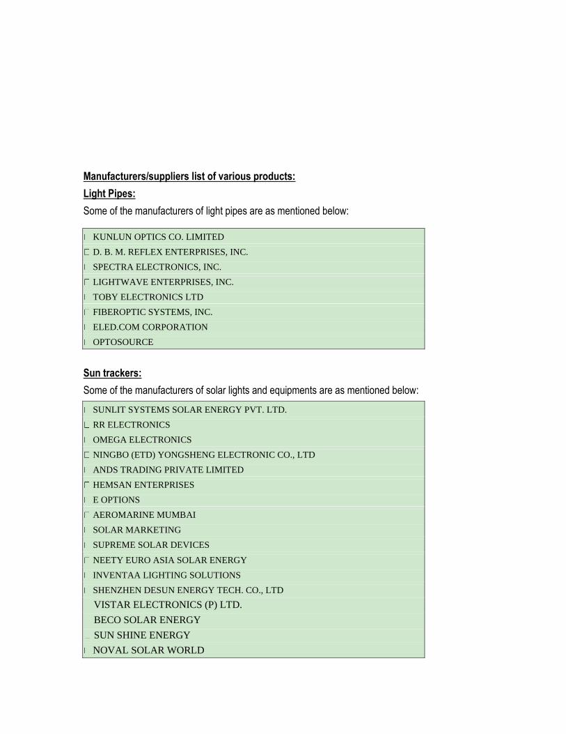
Passive downdraught cooling: In this system, wind catchers guide outside air over water-filled
pots, inducing evaporation and causing a significant drop in temperature before the air enters the
interior. Such wind catchers become primary elements of the architectural form also.
(Source: www.hubpages.com )
Manufacturers/suppliers list of various products:
Light Pipes:
Some of the manufacturers of light pipes are as mentioned below:
KUNLUN OPTICS CO. LIMITED
D. B. M. REFLEX ENTERPRISES, INC.
SPECTRA ELECTRONICS, INC.
LIGHTWAVE ENTERPRISES, INC.
TOBY ELECTRONICS LTD
FIBEROPTIC SYSTEMS, INC.
ELED.COM CORPORATION
OPTOSOURCE
Sun trackers:
Some of the manufacturers of solar lights and equipments are as mentioned below:
SUNLIT SYSTEMS SOLAR ENERGY PVT. LTD.
RR ELECTRONICS
OMEGA ELECTRONICS
NINGBO (ETD) YONGSHENG ELECTRONIC CO., LTD
ANDS TRADING PRIVATE LIMITED
HEMSAN ENTERPRISES
E OPTIONS
AEROMARINE MUMBAI
SOLAR MARKETING
SUPREME SOLAR DEVICES
NEETY EURO ASIA SOLAR ENERGY
INVENTAA LIGHTING SOLUTIONS
SHENZHEN DESUN ENERGY TECH. CO., LTD
VISTAR ELECTRONICS (P) LTD.
BECO SOLAR ENERGY
SUN SHINE ENERGY
NOVAL SOLAR WORLD
INFINITY SOLAR
FRONWAY ENTERPRISE CO. LTD
FRONWAY ENTERPRISE CO. LTD
SIANT ENERGY SOLUTIONS PVT LTD.
SOLARIZER - RR TECHNOLOGIES
SOLAR BIOTECH INC.
SUNRISE SOLAR PVT LTD
ADITYA SOLAR PHOTOVOLTAIC SYSTEMS
REENTEK INDIA PRIVATE LIMITED
SOLAR TECHNICS
CIRCA SOLAR ENERGY INC.
GREEN ENERGY TECHNOLOGY CO., LTD
ER SOLAR SYSTEMS
Daylight controls:
Some of the manufacturers of Daylight controls are as mentioned below:
OSRAM INDIA LTD
WIPRO LIGHTING
PHILIPS (HELIO)-ECHELON'S LONWORKS NETWORKING SERVICES
GE LIGHTING (PROSYS)
HAVELLS INDIA LTD
HONEYWELL ELECTRICAL DEVICES AND SYSTEMS INDIA LTD
SURYA ROSHNI LTD
PHOENIX
RELIANCE INDUSTRIES LTD
ALIEN ENERGY PVT LTD
ANKUR LIGHTING
CROMPTON GREAVES LTD
ECE INDUSTRIES LTD
ELMECH GROUP
INDO ASIAN FUSE GEAR LTD
LEGRAND LUMINAIRES PVT LTD
AVAIDS TECHNOVATORS PVT. LTD.
INSTAPOWER LTD.
VISA ELECTRONIC DEVICES
JOB TRACK MANAGEMENT SERVICES

MICROBIT CONTROLS
DARBARI INDUSTRIES
ADVENT ELECTROMAGNETIC TECHNOLOGIES
MARG ENTERPRISES
ACTIS TECHNOLOGIES PRIVATE LIMITED
UNILITE INDUSTRIES
POWER ELECTRONICS, PUNE
Overview of ECBC envelope:
The building envelope refers to the exterior façade, and is comprised of opaque components and
fenestration systems. Opaque components include walls, roofs, slabs on grade (in touch with
ground), basement walls, and opaque doors. Fenestration systems include windows, skylights,
ventilators, and doors that are more than one-half glazed. The envelope protects the building‘s
interiors and occupants from the weather conditions and shields them from other external factors
e.g: noise, pollution, etc
Envelope design strongly affects the visual and thermal comfort of the occupants, as well as
energy consumption in the building. The design of the building envelope is generally responsible
of the architect. The building designer is responsible for making sure that the building envelope is
energy-efficient and complies with the mandatory and prescriptive requirements of the code.
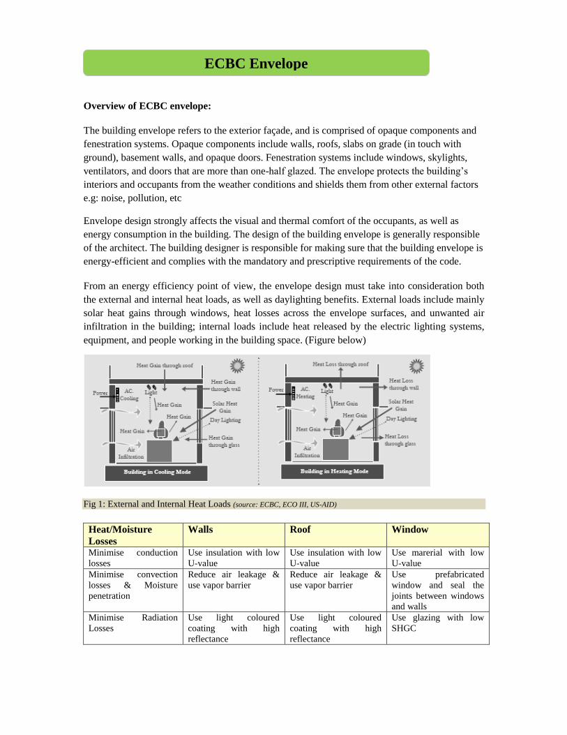
From an energy efficiency point of view, the envelope design must take into consideration both
the external and internal heat loads, as well as daylighting benefits. External loads include mainly
solar heat gains through windows, heat losses across the envelope surfaces, and unwanted air
infiltration in the building; internal loads include heat released by the electric lighting systems,
equipment, and people working in the building space. (Figure below)
Fig 1: External and Internal Heat Loads (source: ECBC, ECO III, US-AID)
Heat/Moisture
Losses
Walls Roof Window
Minimise conduction
losses
Use insulation with low
U-value
Use insulation with low
U-value
Use marerial with low
U-value
Minimise convection
losses & Moisture
penetration
Reduce air leakage &
use vapor barrier
Reduce air leakage &
use vapor barrier
Use prefabricated
window and seal the
joints between windows
and walls
Minimise Radiation
Losses
Use light coloured
coating with high
reflectance
Use light coloured
coating with high
reflectance
Use glazing with low
SHGC
ECBC Envelope
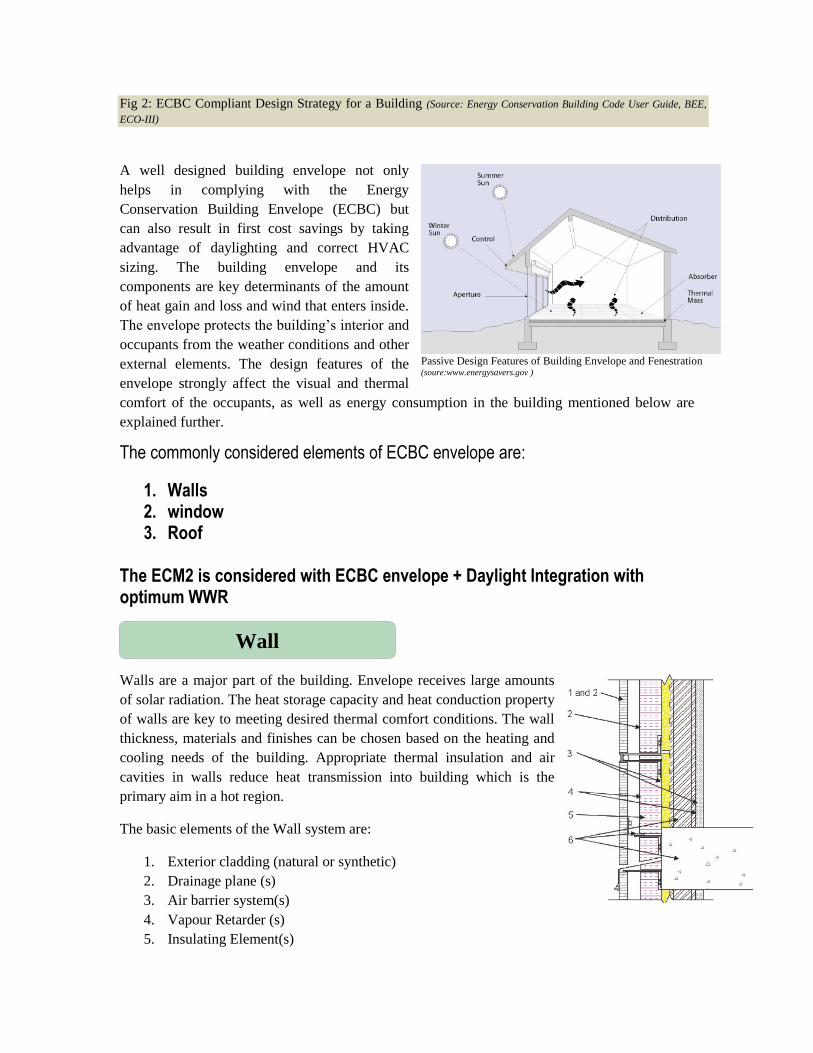
Fig 2: ECBC Compliant Design Strategy for a Building (Source: Energy Conservation Building Code User Guide, BEE,
ECO-III)
A well designed building envelope not only
helps in complying with the Energy
Conservation Building Envelope (ECBC) but
can also result in first cost savings by taking
advantage of daylighting and correct HVAC
sizing. The building envelope and its
components are key determinants of the amount
of heat gain and loss and wind that enters inside.
The envelope protects the building‘s interior and
occupants from the weather conditions and other
external elements. The design features of the
envelope strongly affect the visual and thermal
comfort of the occupants, as well as energy consumption in the building mentioned below are
explained further.
The commonly considered elements of ECBC envelope are:
1. Walls 2. window 3. Roof
The ECM2 is considered with ECBC envelope + Daylight Integration with optimum WWR Walls are a major part of the building. Envelope receives large amounts
of solar radiation. The heat storage capacity and heat conduction property
of walls are key to meeting desired thermal comfort conditions. The wall
thickness, materials and finishes can be chosen based on the heating and
cooling needs of the building. Appropriate thermal insulation and air
cavities in walls reduce heat transmission into building which is the
primary aim in a hot region.
The basic elements of the Wall system are:
1. Exterior cladding (natural or synthetic)
2. Drainage plane (s)
3. Air barrier system(s)
4. Vapour Retarder (s)
5. Insulating Element(s)
Passive Design Features of Building Envelope and Fenestration (soure:www.energysavers.gov )
Wall

6. Structural elements
Thermal storage / thermal capacity: Thermal capacity is the measure of the amount of energy
required to raise the temperature of a layer of material, it
is a product of density multiplied by specific heat and
volume of the construction layer. The main effect of heat
storage within the building structure is to moderate
fluctuation in the indoor temperature.
In a building system, we can understand thermal mass as the ability of a building material to store
heat energy to balance the fluctuations in the heat energy requirements or room temperature in the
building due to varying outside air temperature. The capacity to store heat depends upon the mass
and therefore on the density of the material as well as on its specific heat capacity. Thus, high
density materials such as concrete, bricks, stone are said to have high thermal mass owing to their
high capacity to store heat while lightweight materials such as wood, or plastics have low thermal
mass. The heat storing capacity of the building materials help achieve thermal comfort conditions
by providing a time delay. This thermal storage effect increases with increasing compactness,
density and specific heat capacity of materials.
Thermal performance of walls can be improved by following ways:
1. Increasing wall thickness
2. Providing air cavity between walls and hollow masonry blocks
3. Applying insulation on the external surface.
4. Applying light coloured distemper on the exposed side of the wall.
Conductance: Conductivity (K) is defined as the rate of heat flow through a unit area of unit thickness of the
material, by a unit temperature difference between the two sides. The unit is W/mK (Watt per
metre - degree Kelvin). The conductivity value varies from 0.03 W/mK for insulators to
400W/mK for metals. Materials with lower conductivity are preferred, as they are better
insulators and would reduce the external heat gains from the envelope.
Walls-insulation: Thermal insulation is of great value when a building requires
mechanical heating or cooling insulation helps reduce the space-
conditioning loads. Location of insulation and its optimum thickness
are important. In hot climate, insulation is placed on the outer face
(facing exterior) of the wall so that thermal mass of the wall is likely
coupled with the external source and strongly coupled with the
interior (Bansal, Hauser, Minke 1994). Fig 4 Exterior wall insulation
How Thermal Mass of a Building Works (source: www.eslarp.uiuc.edu )
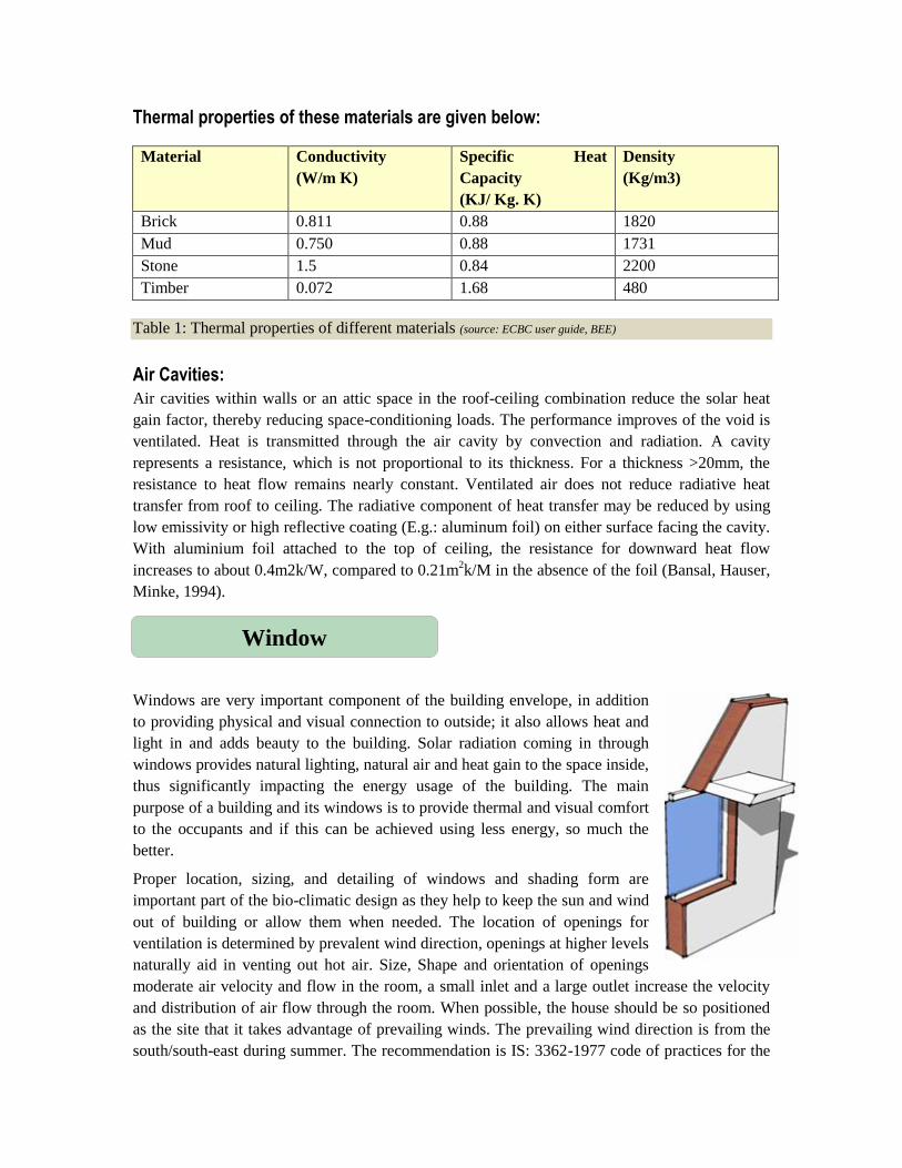
Thermal properties of these materials are given below:
Material Conductivity
(W/m K)
Specific Heat
Capacity
(KJ/ Kg. K)
Density
(Kg/m3)
Brick 0.811 0.88 1820
Mud 0.750 0.88 1731
Stone 1.5 0.84 2200
Timber 0.072 1.68 480
Table 1: Thermal properties of different materials (source: ECBC user guide, BEE)
Air Cavities:
Air cavities within walls or an attic space in the roof-ceiling combination reduce the solar heat
gain factor, thereby reducing space-conditioning loads. The performance improves of the void is
ventilated. Heat is transmitted through the air cavity by convection and radiation. A cavity
represents a resistance, which is not proportional to its thickness. For a thickness >20mm, the
resistance to heat flow remains nearly constant. Ventilated air does not reduce radiative heat
transfer from roof to ceiling. The radiative component of heat transfer may be reduced by using
low emissivity or high reflective coating (E.g.: aluminum foil) on either surface facing the cavity.
With aluminium foil attached to the top of ceiling, the resistance for downward heat flow
increases to about 0.4m2k/W, compared to 0.21m2k/M in the absence of the foil (Bansal, Hauser,
Minke, 1994).
Windows are very important component of the building envelope, in addition
to providing physical and visual connection to outside; it also allows heat and
light in and adds beauty to the building. Solar radiation coming in through
windows provides natural lighting, natural air and heat gain to the space inside,
thus significantly impacting the energy usage of the building. The main
purpose of a building and its windows is to provide thermal and visual comfort
to the occupants and if this can be achieved using less energy, so much the
better.
Proper location, sizing, and detailing of windows and shading form are
important part of the bio-climatic design as they help to keep the sun and wind
out of building or allow them when needed. The location of openings for
ventilation is determined by prevalent wind direction, openings at higher levels
naturally aid in venting out hot air. Size, Shape and orientation of openings
moderate air velocity and flow in the room, a small inlet and a large outlet increase the velocity
and distribution of air flow through the room. When possible, the house should be so positioned
as the site that it takes advantage of prevailing winds. The prevailing wind direction is from the
south/south-east during summer. The recommendation is IS: 3362-1977 code of practices for the
Window
Strip windows
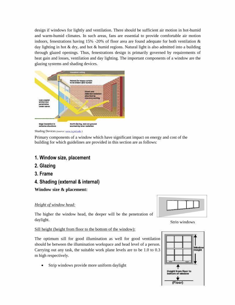
design if windows for lightly and ventilation. There should be sufficient air motion in hot-humid
and warm-humid climates. In such areas, fans are essential to provide comfortable air motion
indoors, fenestrations having 15% -20% of floor area are found adequate for both ventilation &
day lighting in hot & dry, and hot & humid regions. Natural light is also admitted into a building
through glazed openings. Thus, fenestrations design is primarily governed by requirements of
heat gain and losses, ventilation and day lighting. The important components of a window are the
glazing systems and shading devices.
Shading Devices (source: www.is.jnit.edu )
Primary components of a window which have significant impact on energy and cost of the
building for which guidelines are provided in this section are as follows:
1. Window size, placement
2. Glazing
3. Frame
4. Shading (external & internal)
Window size & placement:
Height of window head:
The higher the window head, the deeper will be the penetration of
daylight.
Sill height (height from floor to the bottom of the window):
The optimum sill for good illumination as well for good ventilation
should be between the illumination workspace and head level of a person.
Carrying out any task, the suitable work plane levels are to be 1.0 to 0.3
m high respectively.
Strip windows provide more uniform daylight
Punched windows should be paired with work areas to avoid creating contrasts of light
and dark areas.
Avoid big windows close to task areas since they can be source of thermal discomfort.
Also larger the windows, the more important glazing selection and shading effectiveness are to
control glare and heat gain.
Use separate apertures for view and daylight—for good day lighting and glare control separate
the view and light windows. Light window should have clear glass for maximum daylight
penetration. Tinted glass could be used below for glare control. The structure in between the two
provides a visual break and an opportunity to attach light shelf or shading device.
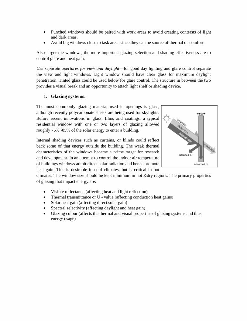
1. Glazing systems:
The most commonly glazing material used in openings is glass,
although recently polycarbonate sheets are being used for skylights.
Before recent innovations in glass, films and coatings, a typical
residential window with one or two layers of glazing allowed
roughly 75% -85% of the solar energy to enter a building.
Internal shading devices such as curtains, or blinds could reflect
back some of that energy outside the building. The weak thermal
characteristics of the windows became a prime target for research
and development. In an attempt to control the indoor air temperature
of buildings windows admit direct solar radiation and hence promote
heat gain. This is desirable in cold climates, but is critical in hot
climates. The window size should be kept minimum in hot &dry regions. The primary properties
of glazing that impact energy are:
Visible reflectance (affecting heat and light reflection)
Thermal transmittance or U - value (affecting conduction heat gains)
Solar heat gain (affecting direct solar gain)
Spectral selectivity (affecting daylight and heat gain)
Glazing colour (affects the thermal and visual properties of glazing systems and thus
energy usage)
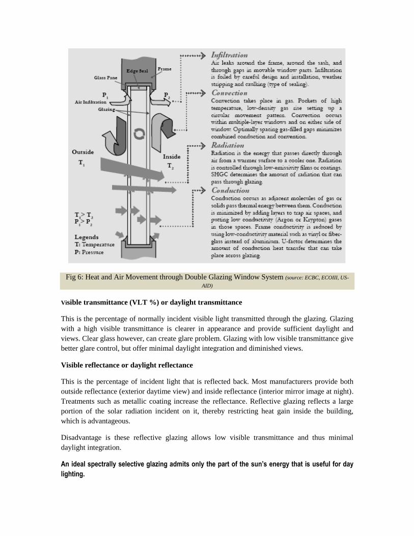
Fig 6: Heat and Air Movement through Double Glazing Window System (source: ECBC, ECOIII, US-
AID)
Visible transmittance (VLT %) or daylight transmittance
This is the percentage of normally incident visible light transmitted through the glazing. Glazing
with a high visible transmittance is clearer in appearance and provide sufficient daylight and
views. Clear glass however, can create glare problem. Glazing with low visible transmittance give
better glare control, but offer minimal daylight integration and diminished views.
Visible reflectance or daylight reflectance
This is the percentage of incident light that is reflected back. Most manufacturers provide both
outside reflectance (exterior daytime view) and inside reflectance (interior mirror image at night).
Treatments such as metallic coating increase the reflectance. Reflective glazing reflects a large
portion of the solar radiation incident on it, thereby restricting heat gain inside the building,
which is advantageous.
Disadvantage is these reflective glazing allows low visible transmittance and thus minimal
daylight integration.
An ideal spectrally selective glazing admits only the part of the sun’s energy that is useful for day
lighting.

Type U value VLT
Clear glass 3.16 79%
Body tinted 3.24 65%
Hard coated: solar control 3.27 24%
Soft coated: solar control 3.08 15%
Low E 2.33 61%
Solar control+ low E 1.77 41%
Table 7: Typical optical and thermal properties for high-performance glazing options
Solar heat gain coefficient (SHGC or shading coefficient)
These are the indicators of total solar heat gain through a
glazing. SHGC is the ratio of the solar heat gain entering the
space through the fenestration area to the incident solar
radiation. Solar heat gains include directly transmitted solar
heat and absorbed solar radiation, which is then re radiated,
conducted or convected into the space. These indices are
dimensionless numbers between 0 and 1 that indicate the total
heat transfer of the sun‘s radiation. These properties are widely
used in cooling load calculations. Glass with a lower SHGC or
SC (Shading coefficient) helps in reducing cooling loads in hot
climate zones.
However, glass with a low SHGC also usually has low VLT. Hence use of glass with spectral
selectivity is recommended for day use air conditioned buildings to enhance day lighting and
reduce cooling loads. In air conditioned buildings, it is mandatory to achieve SHGC lower or
equal to that recommended by ECBC for various window wall ratios.
Adjusted SHGC
Adjusted SHGC is the cumulative solar heat gain coefficient of the window with both the glass
and shading devices (overhang, vertical fin or both).
Adjusted SHGC, which accounts for overhang and or side fins, is calculated by multiplying the
SHGC of the unshaded glass times a multiplication factor (M).
Adjusted SHGC = M * SHGC of glass
The multiplication factor (M) is identified for various projection factors (as per ECBC
guidelines); whenever the fenestration is provided with overhangs and/ or vertical fins, a separate
―M‖ factor shall be determined for each orientation and unique shading condition. The
multiplication factor is derived from the projection factor and it is calculated based on the four
ranges of PF (such as from 0.25 to 0.49, 0.50 to 0.74, 0.75 to 0.99 and 1.00 or more).
Glazing types and materials:
Until recently, single pane clear glass was the primary glazing material used in windows. The
past few decades have seen immense changes in glazing technology. Several types of advanced
glazing systems are available to help control heat loss or gain. The advanced glazing include
double and triple pane windows with coatings such as low - e (low emissivity)/ spectrally
selective, heat absorbing (tinted), or reflective, gas filled windows and windows based on
combination of these options.
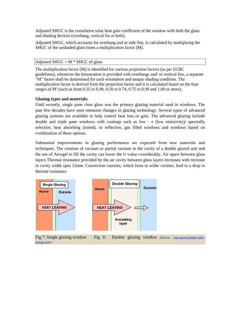
Substantial improvements in glazing performance are expected from new materials and
techniques. The creation of vacuum or partial vacuum in the cavity of a double glazed unit and
the use of Aerogel to fill the cavity can lower the U-value considerably. Air space between glass
layers Thermal resistance provided by the air cavity between glass layers increases with increase
in cavity width upto 12mm. Convection currents, which form in wider cavities, lead to a drop in
thermal resistance
Fig 7: Single glazing window Fig 8: Double glazing window (Source: www.green-planet-solar-
energy.com )

Fig 8: Glazing materials (Source: www.gmpartitions.net )
Insulated glazing units
Insulating glazing units are hermetically sealed, multiple pane assembles consisting of two or
more glazing layers held and bonded at their perimeter by a space bar typically containing a
desiccant material. The glazing used in IGUs could be clear, tinted or coated or reflective as
mentioned above. The spacer serves to separate the panes of glass and to provide a surface for
primary and secondary sealant adhesion, since heat transfer at the edge of the IGU is greater than
its centre. The choice of material for spacer is critical to the IGUs performance. It is advisable to
use SS, galvanized steel, polymers or foamed silicon which have lower conductivities than
aluminium. The hermetically sealed space between glass panes is most often filled with air, argon
and krypton being two other alternatives.
Latest trends in glazing systems
a) Switchable glazing : Switchable glazing will enable the user to change the optical or thermal
properties of sealed glazed units. The most useful and potentially applicable switchable property
is the chromogenic phenomenon in which materials change their reflectivity and absorptivity.
Examples of chromogenic proceeese are: thermochromic, electrochromic and photochromic
materials. Thermochromic glazing changes optical properties in response to temperature changes.
It consists of mainly liquids or gels sandwitched between layers of glazing. Thermochromic
windows are designed to block solar gain. A drawback is that they reduce visible light
transmission as well. Electrochromic glazing changes optical properties when an electric current
goes through the unit. A thin mettalic film is deposited on the glass similar to low emissivity
coatings. Another technique involves sandwiching a liquid quartz film between two layers of
glazing. Photochromic materials change their properties in response to light. Photo gray
sunglasses are best example. When photochromic materials change their transmittance, the
absorptivity is increased, thus causing glass to absorb more heat. On sunny, colds days, they
absorb solar heat and room source heat and then radiate some heat back to the surroundings. On
sunny, hot days, they do not reject as much solar heat as reflective glass.

b) Evacuated glazing : Evacuated, sealed insulated glazing is designed to achieve higher levels of
thermal performance by using a vacuum to inhibit any kind conductive or convective heat losses.
Flip windows for improved performance in summers and winters. The double pane absorptive
glazing system for hot climates has a useful feature for regions of composite climate, having both
heating and cooling seasons.
If the positions of the two glass panes are flipped over from their summertime positions during
the cold winter, the system converts to a solar radiant heater. In the cold day position, solar
radiation passes through the clear outer pane is absorbed by the inner pane, which heats up and
then this heat is transmitted to the inside, warming the building. The low - e coating on the inner
pane now reduces the radiation of heat from this hot inner pane to the cold outer one, trapping the
heat inside. Flipping it back over makes it a hot climate glazing system since the solar heat is now
absorbed in the outer pane of glass, which is insulated from the interior of the building.
Frame
The type and quality of window frame affects a window‘s air infiltration and heat gain / heat loss
characteristics. There are three kinds of framing material mostly used which are metal, wood and
polymers.
Wood has a good structural integrity and insulating values but low resistance to external
weather conditions.
Metal frames have poor thermal performance, but have excellent structural characteristics
and durability.
Aluminium is the most preferred metal for frames, but it is highly conductive and its
thermal performance can be improved with a thermal break (a non metal component
which separates the metal frame exposed to the outside from surfaces exposed to the
inside.)
Vinyl window frames which are primarily made from polyvinyl chloride (PVC) offer
many advantages. Available in wide range of style and shapes PVC frames has high R–
value (Resistance value) and low maintenance.
U-value:
Table below shows how with the usage of different frame materials,
overall U– value varies. The below exercise was carried out using
WINDOW 5 as a tool, where glass and window size was not
changed, only on changing the frame difference in U– value was
observed. It should also be noted that the U-value of glass is lesser
than the overall u-value of the entire window, which is calculated by
the area weighted method, which includes the U– value of both
glass and frame.
Daylighting and Window design:
Day lighting is utilization of light from the sun and sky to complement or replace electric light.
Appropriate fenestration and lighting controls can be used to modulate daylight admittance and to
reduce electric lighting, while meeting the occupants‘ visual comfort.
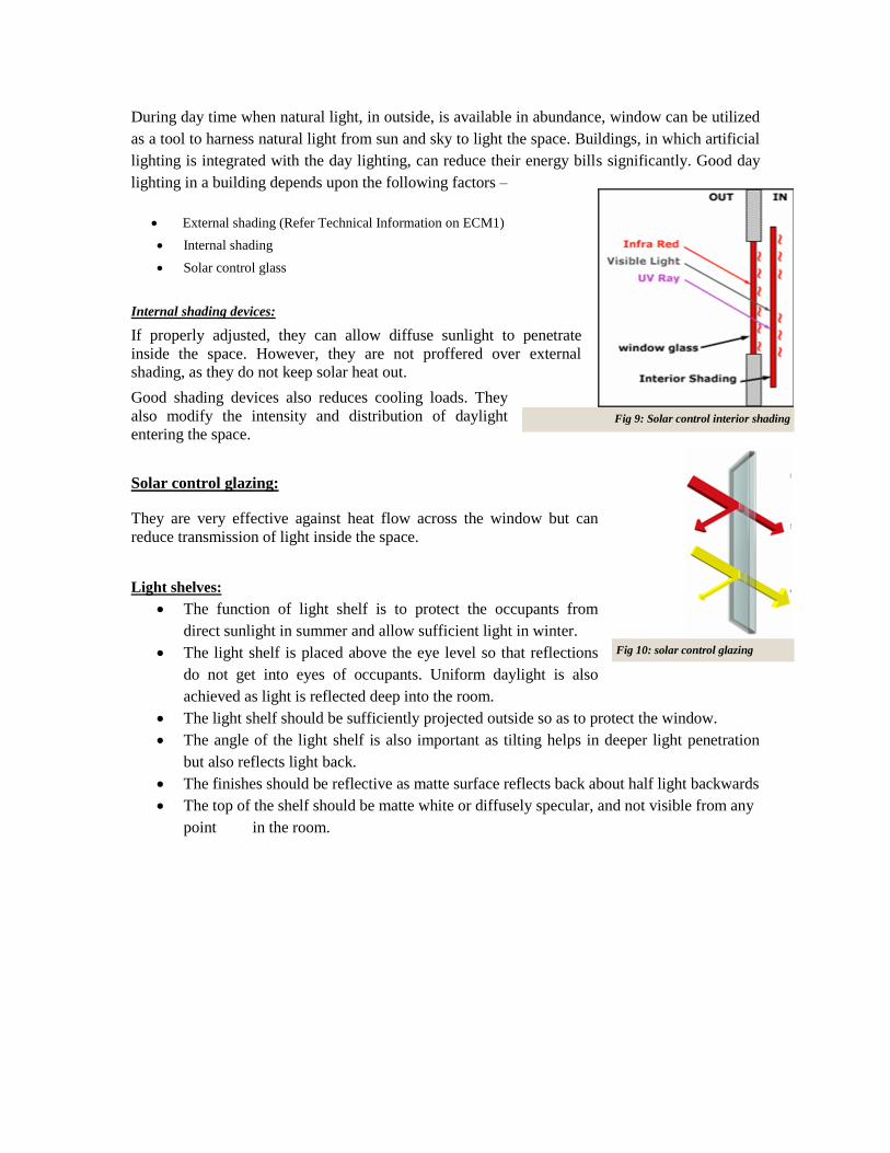
Fig 9: Solar control interior shading
During day time when natural light, in outside, is available in abundance, window can be utilized
as a tool to harness natural light from sun and sky to light the space. Buildings, in which artificial
lighting is integrated with the day lighting, can reduce their energy bills significantly. Good day
lighting in a building depends upon the following factors –
External shading (Refer Technical Information on ECM1)
Internal shading
Solar control glass
Internal shading devices:
If properly adjusted, they can allow diffuse sunlight to penetrate
inside the space. However, they are not proffered over external
shading, as they do not keep solar heat out.
Good shading devices also reduces cooling loads. They
also modify the intensity and distribution of daylight
entering the space.
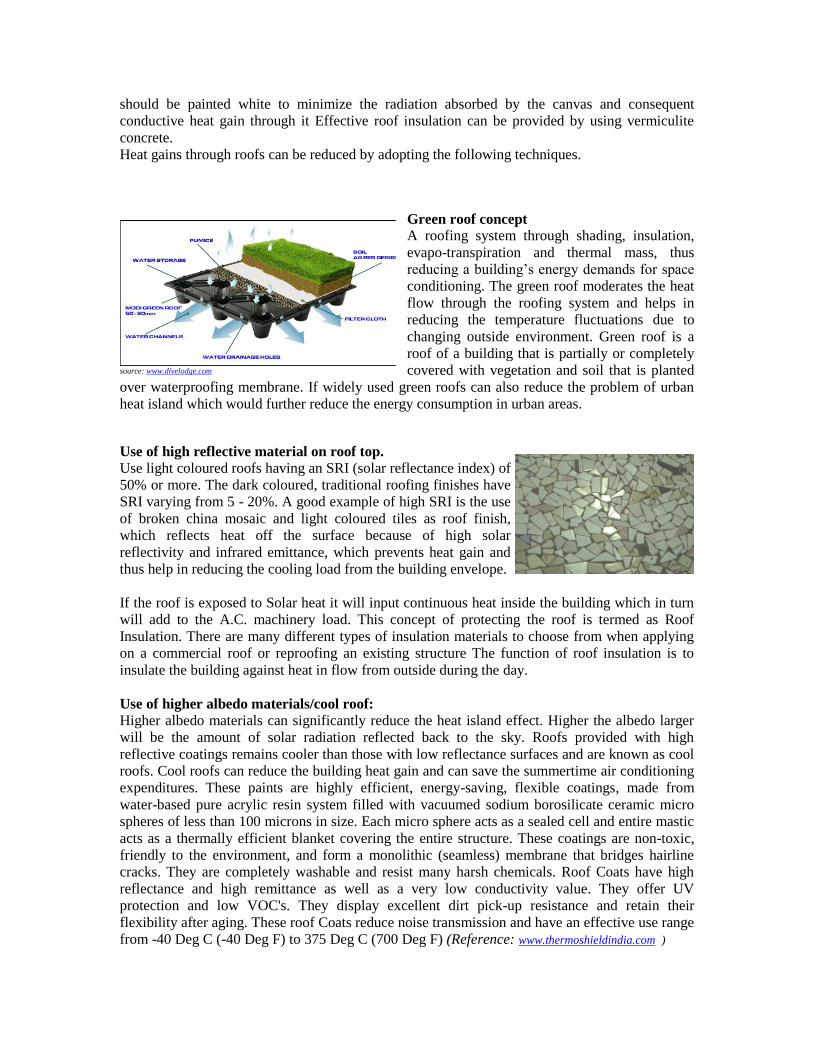
Solar control glazing:
They are very effective against heat flow across the window but can
reduce transmission of light inside the space.
Light shelves:
The function of light shelf is to protect the occupants from
direct sunlight in summer and allow sufficient light in winter.
The light shelf is placed above the eye level so that reflections
do not get into eyes of occupants. Uniform daylight is also
achieved as light is reflected deep into the room.
The light shelf should be sufficiently projected outside so as to protect the window.
The angle of the light shelf is also important as tilting helps in deeper light penetration
but also reflects light back.
The finishes should be reflective as matte surface reflects back about half light backwards
The top of the shelf should be matte white or diffusely specular, and not visible from any
point in the room.
Fig 10: solar control glazing

Fig 11: Modelling of Light shelves
Conventional Roof Insulation Practices
In India Roof Insulation with conventional materials like Foam
Concrete, Mud Faska, Brick Bat Coba has been practiced since ages.
However these products are quite heavy and add dead load to the roof
slab. Moreover the thermal conductivity value is very high which
results into higher thickness application without much benefit. These
products have the tendency to develop cracks and as a result water
absorption takes place. Moreover, the products are open cell and
porous type which results into water absorption. This application also calls for good
workmanship.
What types of roofing products are available?
Products for low-slope roofs, found on commercial and industrial buildings fall into two
categories: single-ply materials and coatings. Single-ply materials are large sheets of pre-made
roofing that are mechanically fastened over the existing roof and sealed at the seams. Coatings are
applied using rollers, sprays, or brushes, over an existing clean, leak-free roof surface. Products
for sloped roofs are currently available in clay, or concrete tiles. These products stay cooler by the
use of special pigments that reflect the sun‘s infrared heat. In India, lime coats, white tiles grouted
with white cement, special paints, etc. are used as cool roofing materials.
Energy efficient roof insulations:
The roof requires significant solar radiation and plays an important role in heat gain/losses, day
lighting and ventilation. Depending on the climatic needs, proper roof treatment is essential. In a
hot region, the roof should have enough insulating properties to minimize heat gains. A few roof
protection methods are as follows:
A cover of decidous plants or creepers can be provided. Evaporation from roof surfaces will keep
the rooms cool. The entire roof surface can be covered with inverted earthen pots. It is also an
insulated cover of still air over the roof shading device. This can be mounted close to the roof in
the day and can be rolled to permit radiative cooling at night. The upper surfaces of the canvas
(Source: www.construction-int.com)
Roof
should be painted white to minimize the radiation absorbed by the canvas and consequent
conductive heat gain through it Effective roof insulation can be provided by using vermiculite
concrete.
Heat gains through roofs can be reduced by adopting the following techniques.
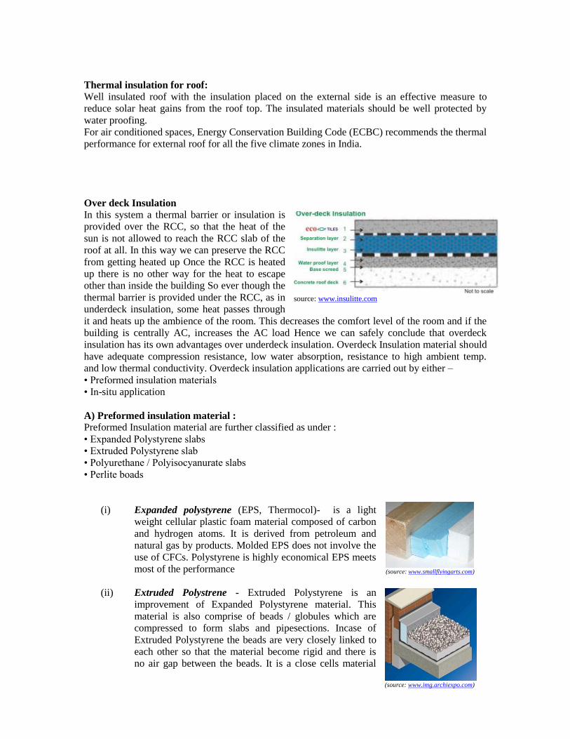
Green roof concept
A roofing system through shading, insulation,
evapo-transpiration and thermal mass, thus
reducing a building‘s energy demands for space
conditioning. The green roof moderates the heat
flow through the roofing system and helps in
reducing the temperature fluctuations due to
changing outside environment. Green roof is a
roof of a building that is partially or completely
covered with vegetation and soil that is planted
over waterproofing membrane. If widely used green roofs can also reduce the problem of urban
heat island which would further reduce the energy consumption in urban areas.
Use of high reflective material on roof top.
Use light coloured roofs having an SRI (solar reflectance index) of
50% or more. The dark coloured, traditional roofing finishes have
SRI varying from 5 - 20%. A good example of high SRI is the use
of broken china mosaic and light coloured tiles as roof finish,
which reflects heat off the surface because of high solar
reflectivity and infrared emittance, which prevents heat gain and
thus help in reducing the cooling load from the building envelope.
If the roof is exposed to Solar heat it will input continuous heat inside the building which in turn
will add to the A.C. machinery load. This concept of protecting the roof is termed as Roof
Insulation. There are many different types of insulation materials to choose from when applying
on a commercial roof or reproofing an existing structure The function of roof insulation is to
insulate the building against heat in flow from outside during the day.
Use of higher albedo materials/cool roof:
Higher albedo materials can significantly reduce the heat island effect. Higher the albedo larger
will be the amount of solar radiation reflected back to the sky. Roofs provided with high
reflective coatings remains cooler than those with low reflectance surfaces and are known as cool
roofs. Cool roofs can reduce the building heat gain and can save the summertime air conditioning
expenditures. These paints are highly efficient, energy-saving, flexible coatings, made from
water-based pure acrylic resin system filled with vacuumed sodium borosilicate ceramic micro
spheres of less than 100 microns in size. Each micro sphere acts as a sealed cell and entire mastic
acts as a thermally efficient blanket covering the entire structure. These coatings are non-toxic,
friendly to the environment, and form a monolithic (seamless) membrane that bridges hairline
cracks. They are completely washable and resist many harsh chemicals. Roof Coats have high
reflectance and high remittance as well as a very low conductivity value. They offer UV
protection and low VOC's. They display excellent dirt pick-up resistance and retain their
flexibility after aging. These roof Coats reduce noise transmission and have an effective use range
from -40 Deg C (-40 Deg F) to 375 Deg C (700 Deg F) (Reference: www.thermoshieldindia.com )
source: www.divelodge.com
(source: www.smallflyingarts.com)
Thermal insulation for roof:
Well insulated roof with the insulation placed on the external side is an effective measure to
reduce solar heat gains from the roof top. The insulated materials should be well protected by
water proofing.
For air conditioned spaces, Energy Conservation Building Code (ECBC) recommends the thermal
performance for external roof for all the five climate zones in India.
Over deck Insulation
In this system a thermal barrier or insulation is
provided over the RCC, so that the heat of the
sun is not allowed to reach the RCC slab of the
roof at all. In this way we can preserve the RCC
from getting heated up Once the RCC is heated
up there is no other way for the heat to escape
other than inside the building So ever though the
thermal barrier is provided under the RCC, as in
underdeck insulation, some heat passes through
it and heats up the ambience of the room. This decreases the comfort level of the room and if the
building is centrally AC, increases the AC load Hence we can safely conclude that overdeck
insulation has its own advantages over underdeck insulation. Overdeck Insulation material should
have adequate compression resistance, low water absorption, resistance to high ambient temp.
and low thermal conductivity. Overdeck insulation applications are carried out by either –
• Preformed insulation materials
• In-situ application
A) Preformed insulation material :
Preformed Insulation material are further classified as under :
• Expanded Polystyrene slabs
• Extruded Polystyrene slab
• Polyurethane / Polyisocyanurate slabs
• Perlite boads
(i) Expanded polystyrene (EPS, Thermocol)- is a light
weight cellular plastic foam material composed of carbon
and hydrogen atoms. It is derived from petroleum and
natural gas by products. Molded EPS does not involve the
use of CFCs. Polystyrene is highly economical EPS meets
most of the performance
(ii) Extruded Polystrene - Extruded Polystyrene is an
improvement of Expanded Polystyrene material. This
material is also comprise of beads / globules which are
compressed to form slabs and pipesections. Incase of
Extruded Polystyrene the beads are very closely linked to
each other so that the material become rigid and there is
no air gap between the beads. It is a close cells material
source: www.insulitte.com
(source: www.img.archiexpo.com)
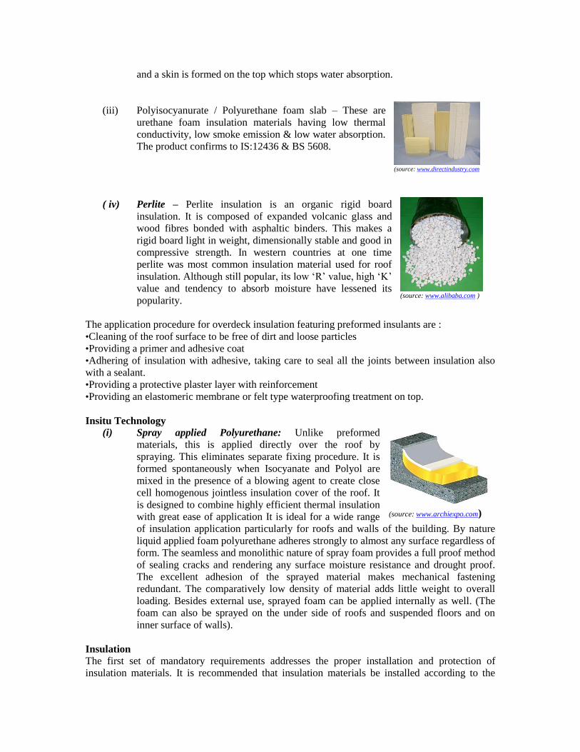
and a skin is formed on the top which stops water absorption.
(iii) Polyisocyanurate / Polyurethane foam slab – These are
urethane foam insulation materials having low thermal
conductivity, low smoke emission & low water absorption.
The product confirms to IS:12436 & BS 5608.
( iv) Perlite – Perlite insulation is an organic rigid board
insulation. It is composed of expanded volcanic glass and
wood fibres bonded with asphaltic binders. This makes a
rigid board light in weight, dimensionally stable and good in
compressive strength. In western countries at one time
perlite was most common insulation material used for roof
insulation. Although still popular, its low ‗R‘ value, high ‗K‘
value and tendency to absorb moisture have lessened its
popularity.
The application procedure for overdeck insulation featuring preformed insulants are :
•Cleaning of the roof surface to be free of dirt and loose particles
•Providing a primer and adhesive coat
•Adhering of insulation with adhesive, taking care to seal all the joints between insulation also
with a sealant.
•Providing a protective plaster layer with reinforcement
•Providing an elastomeric membrane or felt type waterproofing treatment on top.
Insitu Technology
(i) Spray applied Polyurethane: Unlike preformed
materials, this is applied directly over the roof by
spraying. This eliminates separate fixing procedure. It is
formed spontaneously when Isocyanate and Polyol are
mixed in the presence of a blowing agent to create close
cell homogenous jointless insulation cover of the roof. It
is designed to combine highly efficient thermal insulation
with great ease of application It is ideal for a wide range
of insulation application particularly for roofs and walls of the building. By nature
liquid applied foam polyurethane adheres strongly to almost any surface regardless of
form. The seamless and monolithic nature of spray foam provides a full proof method
of sealing cracks and rendering any surface moisture resistance and drought proof.
The excellent adhesion of the sprayed material makes mechanical fastening
redundant. The comparatively low density of material adds little weight to overall
loading. Besides external use, sprayed foam can be applied internally as well. (The
foam can also be sprayed on the under side of roofs and suspended floors and on
inner surface of walls).
Insulation
The first set of mandatory requirements addresses the proper installation and protection of
insulation materials. It is recommended that insulation materials be installed according to the
(source: www.directindustry.com )
(source: www.alibaba.com )
(source: www.archiexpo.com)
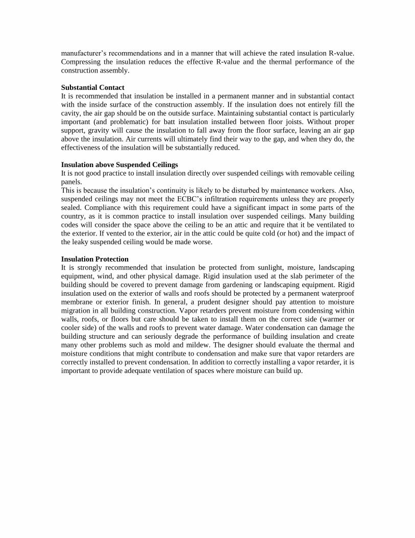
manufacturer‘s recommendations and in a manner that will achieve the rated insulation R-value.
Compressing the insulation reduces the effective R-value and the thermal performance of the
construction assembly.
Substantial Contact
It is recommended that insulation be installed in a permanent manner and in substantial contact
with the inside surface of the construction assembly. If the insulation does not entirely fill the
cavity, the air gap should be on the outside surface. Maintaining substantial contact is particularly
important (and problematic) for batt insulation installed between floor joists. Without proper
support, gravity will cause the insulation to fall away from the floor surface, leaving an air gap
above the insulation. Air currents will ultimately find their way to the gap, and when they do, the
effectiveness of the insulation will be substantially reduced.
Insulation above Suspended Ceilings
It is not good practice to install insulation directly over suspended ceilings with removable ceiling
panels.
This is because the insulation‘s continuity is likely to be disturbed by maintenance workers. Also,
suspended ceilings may not meet the ECBC‘s infiltration requirements unless they are properly
sealed. Compliance with this requirement could have a significant impact in some parts of the
country, as it is common practice to install insulation over suspended ceilings. Many building
codes will consider the space above the ceiling to be an attic and require that it be ventilated to
the exterior. If vented to the exterior, air in the attic could be quite cold (or hot) and the impact of
the leaky suspended ceiling would be made worse.
Insulation Protection
It is strongly recommended that insulation be protected from sunlight, moisture, landscaping
equipment, wind, and other physical damage. Rigid insulation used at the slab perimeter of the
building should be covered to prevent damage from gardening or landscaping equipment. Rigid
insulation used on the exterior of walls and roofs should be protected by a permanent waterproof
membrane or exterior finish. In general, a prudent designer should pay attention to moisture
migration in all building construction. Vapor retarders prevent moisture from condensing within
walls, roofs, or floors but care should be taken to install them on the correct side (warmer or
cooler side) of the walls and roofs to prevent water damage. Water condensation can damage the
building structure and can seriously degrade the performance of building insulation and create
many other problems such as mold and mildew. The designer should evaluate the thermal and
moisture conditions that might contribute to condensation and make sure that vapor retarders are
correctly installed to prevent condensation. In addition to correctly installing a vapor retarder, it is
important to provide adequate ventilation of spaces where moisture can build up.
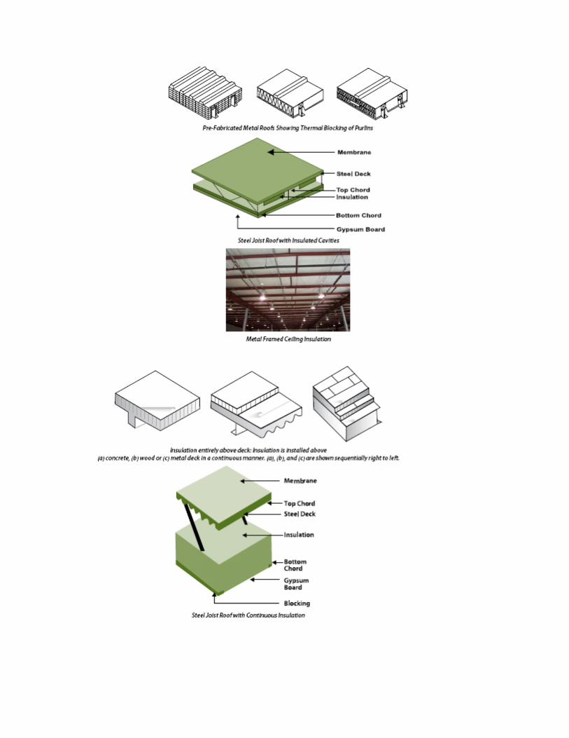
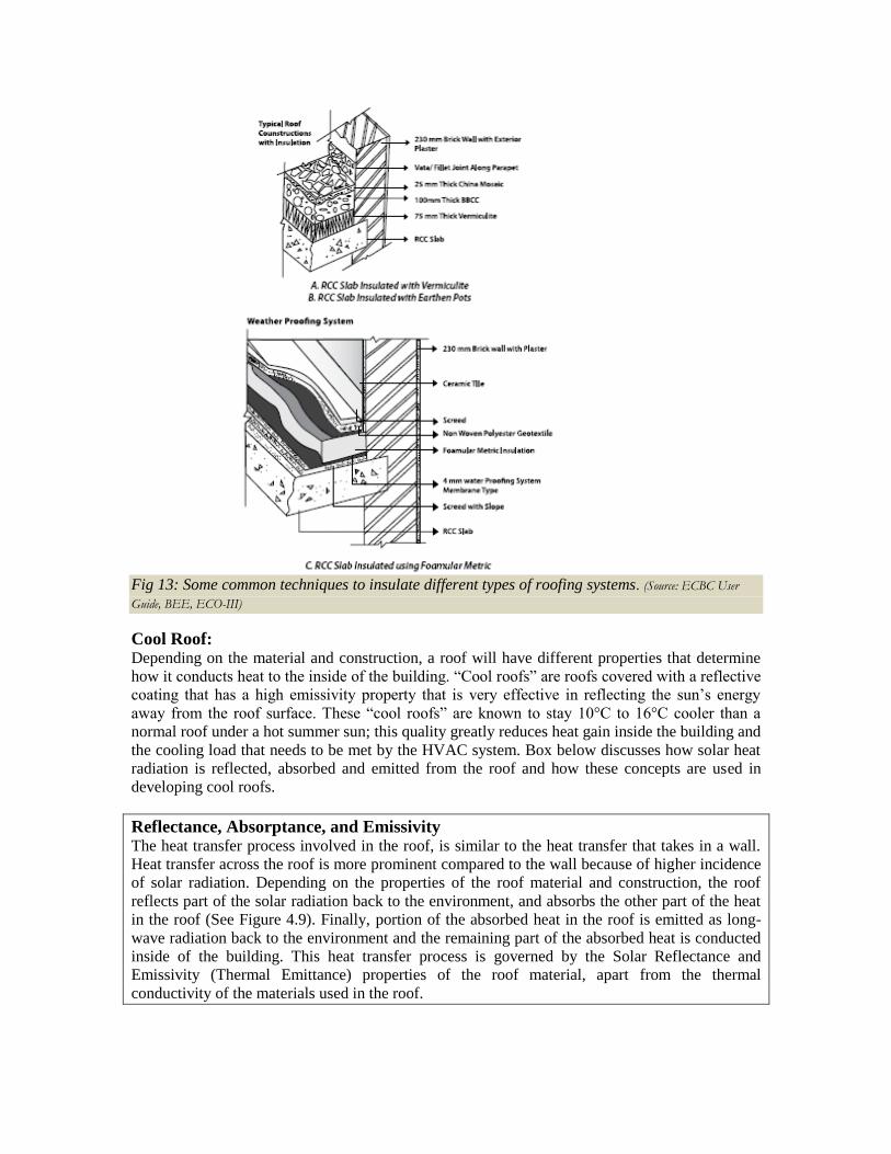
Fig 13: Some common techniques to insulate different types of roofing systems. (Source: ECBC User
Guide, BEE, ECO-III)
Cool Roof: Depending on the material and construction, a roof will have different properties that determine
how it conducts heat to the inside of the building. ―Cool roofs‖ are roofs covered with a reflective
coating that has a high emissivity property that is very effective in reflecting the sun‘s energy
away from the roof surface. These ―cool roofs‖ are known to stay 10°C to 16°C cooler than a
normal roof under a hot summer sun; this quality greatly reduces heat gain inside the building and
the cooling load that needs to be met by the HVAC system. Box below discusses how solar heat
radiation is reflected, absorbed and emitted from the roof and how these concepts are used in
developing cool roofs.
Reflectance, Absorptance, and Emissivity
The heat transfer process involved in the roof, is similar to the heat transfer that takes in a wall.
Heat transfer across the roof is more prominent compared to the wall because of higher incidence
of solar radiation. Depending on the properties of the roof material and construction, the roof
reflects part of the solar radiation back to the environment, and absorbs the other part of the heat
in the roof (See Figure 4.9). Finally, portion of the absorbed heat in the roof is emitted as long-
wave radiation back to the environment and the remaining part of the absorbed heat is conducted
inside of the building. This heat transfer process is governed by the Solar Reflectance and
Emissivity (Thermal Emittance) properties of the roof material, apart from the thermal
conductivity of the materials used in the roof.
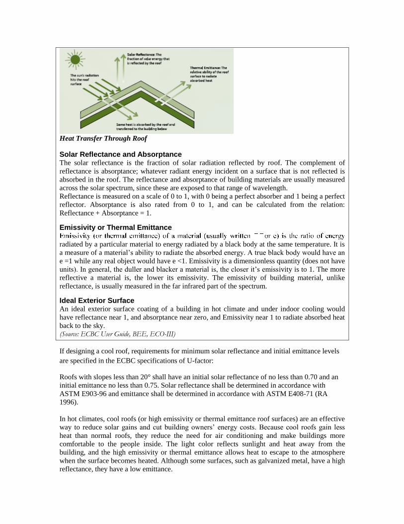
Heat Transfer Through Roof
Solar Reflectance and Absorptance The solar reflectance is the fraction of solar radiation reflected by roof. The complement of
reflectance is absorptance; whatever radiant energy incident on a surface that is not reflected is
absorbed in the roof. The reflectance and absorptance of building materials are usually measured
across the solar spectrum, since these are exposed to that range of wavelength.
Reflectance is measured on a scale of 0 to 1, with 0 being a perfect absorber and 1 being a perfect
reflector. Absorptance is also rated from 0 to 1, and can be calculated from the relation:
Reflectance + Absorptance = 1.
Emissivity or Thermal Emittance
radiated by a particular material to energy radiated by a black body at the same temperature. It is
a measure of a material‘s ability to radiate the absorbed energy. A true black body would have an
e =1 while any real object would have e <1. Emissivity is a dimensionless quantity (does not have
units). In general, the duller and blacker a material is, the closer it‘s emissivity is to 1. The more
reflective a material is, the lower its emissivity. The emissivity of building material, unlike
reflectance, is usually measured in the far infrared part of the spectrum.
Ideal Exterior Surface An ideal exterior surface coating of a building in hot climate and under indoor cooling would
have reflectance near 1, and absorptance near zero, and Emissivity near 1 to radiate absorbed heat
back to the sky. (Source: ECBC User Guide, BEE, ECO-III)
If designing a cool roof, requirements for minimum solar reflectance and initial emittance levels
are specified in the ECBC specifications of U-factor:
Roofs with slopes less than 20° shall have an initial solar reflectance of no less than 0.70 and an
initial emittance no less than 0.75. Solar reflectance shall be determined in accordance with
ASTM E903-96 and emittance shall be determined in accordance with ASTM E408-71 (RA
1996).
In hot climates, cool roofs (or high emissivity or thermal emittance roof surfaces) are an effective
way to reduce solar gains and cut building owners‘ energy costs. Because cool roofs gain less
heat than normal roofs, they reduce the need for air conditioning and make buildings more
comfortable to the people inside. The light color reflects sunlight and heat away from the
building, and the high emissivity or thermal emittance allows heat to escape to the atmosphere
when the surface becomes heated. Although some surfaces, such as galvanized metal, have a high
reflectance, they have a low emittance.
These surfaces reflect heat, but heat that is absorbed cannot escape. Other surfaces, such as dark
paint, have a high emittance but a low reflectance. These surfaces allow heat to escape, but do a
poor job of reflecting heat that strikes the surface.
Most cool roof materials for low-sloped roofs are white or another light color. For steep-sloped
roofs that are often visible from the ground, roofing material manufacturers have developed
popular roof colors other than white that will still reflect solar radiation or emit the sun‘s energy
away from the building.
Cool roofs have other benefits in addition to reducing operating absorbed heat costs. For building
owners, they can cut maintenance costs and increase the life expectancy of the roof. For society in
general, cool roofs can even help to reduce the urban heat island effect and slow down global
warming that makes our cities hotter and produces unhealthy air.
MANUFACTURERS LIST
Manufacturers list of materials that comply with ECBC for wall, window and roof are mentioned below.
Manufacturers list of Wall Insulations:
Some of the manufacturers of solar lights and equipments are as mentioned below. The list
mentioned below is not extensive and has to be checked in the market for more updates and more
information.
BEARDSELL LIMITED
U.P TWIGA FIBERGLASS LIMITED
TROCELLEN
NANOGEL
CANI MERCHANDISING PVT.LTD
SANROK
DOW CHEMICAL INTERNATIONAL PVT.LTD
WACKER POLYMER SYSTEMS GMBH & CO. KG
LLOYD INSULATIONS (INDIA) LTD
FIBREX INDUSTRIES
SUNSULATE INSULATION PVT. LTD
SUZERAIN INSULATORS
SUD AND WAREN PVT LTD
PERFECT PAPERS
MAG HARD INSULATORS
AGNI FIBER BOARDS PVT. LTD
S.S INSULATION
ROCKWOOL (INDIA) LIMITE
KONIFER INDIA
UMANG BOARDS PRIVATE LIMITED
SIGMA SEALING & INSULATION PRIVATE LIMITED
List of Manufacturers:
Some of the important manufacturers list of glass and glass products is mentioned below.The list
of manufacturers mentioned below is not comprehensive and needs to be checked with the
updated list in the market.
SAINT-GOBAIN GLASS INDUSTRIES
GARWARE POLYSTER LIMITED
MEHLER TECHNOLOGIES GMBH
SEJAL GLASS
ASAHI INDIA GLASS LTD
DAFFODIL GLASS
GLASS CONSORTIUM
UNIVERSAL GLASS TRADERS
INDO ALUSYS INDUSTRIES LIMITED
SUPERIOR GLASS
GLASS AND GLAZING SYSTEMS (P) LTD.
HINDUSTAN GLASS WORKS LTD
Manufacturers list of Roof Insulations:
Some of the manufacturers of solar lights and equipments are as mentioned below. The list
mentioned below is not extensive and has to be checked in the market for more updates and more
information.
INDUSTRIAL FOAMS (P) LTD
FALCONN FIBRE
DUGAR INSULATIONS INDIA (P) LTD
AMOL DICALITE LIMITED
MACBERTAN (P) LTD
LLOYD INSULATIONS INDIA (P) LTD
EXCEL COATINGS
SHALAK INTERNATIONAL
OWENS CORNING (INDIA) LTD
OZTEN LTD
SHATEX LUBRZOLE
ENERCON
Daylight Integration
Any lighting scheme interior or exterior can be called an efficient scheme when it provides the
required illuminance level for the application it has been designed while utilizing least amount of
energy. Technical information for achieving efficiency in the lighting scheme for three categories
which are External Lighting, Internal Lighting for Commercial Buildings, and Internal Lighting
for Residential Buildings have been elaborated below-
Optimized Lighting Scheme –
What is an optimized lighting scheme?
Optimized lighting scheme comprises of two key components –
1. Effectiveness of the lighting scheme
2. Efficiency of the lighting scheme
1. Effectiveness of lighting scheme
Effective Lighting Scheme –
A lighting scheme can be called an effective one when it serves the purpose for which it is
designed. The purpose of a lighting scheme is to provide visual comfort for different kind of
activities in different spaces as per various standards. In India we have standard for visual
comfort given in Part 8, Section-1, Table - 4 of Lighting and Ventilation of NBC (National
Building Code of India) 2005 and a lighting scheme will be called effective if it conforms to NBC
2005 recommended illuminance levels for various activities and spaces.
Efficient Lighting scheme –
A lighting scheme is called efficient over the other when for the same visual comfort and usage
pattern it will consume lesser amount of electrical energy. The efficiency in a lighting scheme is
guided by the following three factors –
a. Lighting Power Density
b. Integration of artificial lighting scheme with daylight
c. Lighting controls
a. Lighting Power Density –
Energy efficiency lighting
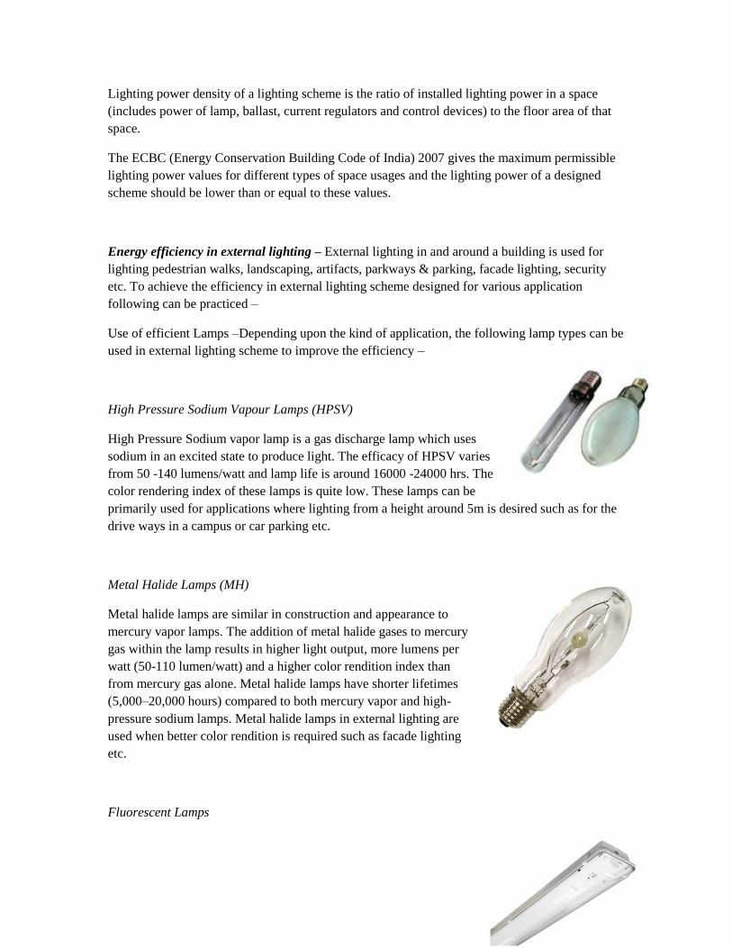
Lighting power density of a lighting scheme is the ratio of installed lighting power in a space
(includes power of lamp, ballast, current regulators and control devices) to the floor area of that
space.
The ECBC (Energy Conservation Building Code of India) 2007 gives the maximum permissible
lighting power values for different types of space usages and the lighting power of a designed
scheme should be lower than or equal to these values.
Energy efficiency in external lighting – External lighting in and around a building is used for
lighting pedestrian walks, landscaping, artifacts, parkways & parking, facade lighting, security
etc. To achieve the efficiency in external lighting scheme designed for various application
following can be practiced –
Use of efficient Lamps –Depending upon the kind of application, the following lamp types can be
used in external lighting scheme to improve the efficiency –
High Pressure Sodium Vapour Lamps (HPSV)
High Pressure Sodium vapor lamp is a gas discharge lamp which uses
sodium in an excited state to produce light. The efficacy of HPSV varies
from 50 -140 lumens/watt and lamp life is around 16000 -24000 hrs. The
color rendering index of these lamps is quite low. These lamps can be
primarily used for applications where lighting from a height around 5m is desired such as for the
drive ways in a campus or car parking etc.
Metal Halide Lamps (MH)
Metal halide lamps are similar in construction and appearance to
mercury vapor lamps. The addition of metal halide gases to mercury
gas within the lamp results in higher light output, more lumens per
watt (50-110 lumen/watt) and a higher color rendition index than
from mercury gas alone. Metal halide lamps have shorter lifetimes
(5,000–20,000 hours) compared to both mercury vapor and high-
pressure sodium lamps. Metal halide lamps in external lighting are
used when better color rendition is required such as facade lighting
etc.
Fluorescent Lamps
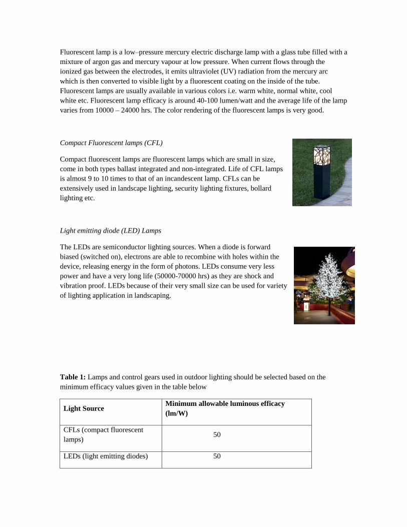
Fluorescent lamp is a low–pressure mercury electric discharge lamp with a glass tube filled with a
mixture of argon gas and mercury vapour at low pressure. When current flows through the
ionized gas between the electrodes, it emits ultraviolet (UV) radiation from the mercury arc
which is then converted to visible light by a fluorescent coating on the inside of the tube.
Fluorescent lamps are usually available in various colors i.e. warm white, normal white, cool
white etc. Fluorescent lamp efficacy is around 40-100 lumen/watt and the average life of the lamp
varies from 10000 – 24000 hrs. The color rendering of the fluorescent lamps is very good.
Compact Fluorescent lamps (CFL)
Compact fluorescent lamps are fluorescent lamps which are small in size,
come in both types ballast integrated and non-integrated. Life of CFL lamps
is almost 9 to 10 times to that of an incandescent lamp. CFLs can be
extensively used in landscape lighting, security lighting fixtures, bollard
lighting etc.
Light emitting diode (LED) Lamps
The LEDs are semiconductor lighting sources. When a diode is forward
biased (switched on), electrons are able to recombine with holes within the
device, releasing energy in the form of photons. LEDs consume very less
power and have a very long life (50000-70000 hrs) as they are shock and
vibration proof. LEDs because of their very small size can be used for variety
of lighting application in landscaping.
Table 1: Lamps and control gears used in outdoor lighting should be selected based on the
minimum efficacy values given in the table below
Light Source Minimum allowable luminous efficacy
(lm/W)
CFLs (compact fluorescent
lamps) 50
LEDs (light emitting diodes) 50
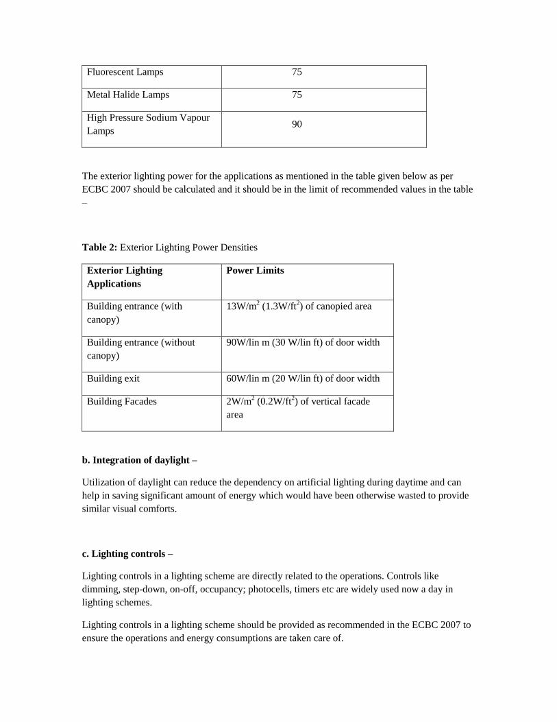
Fluorescent Lamps 75
Metal Halide Lamps 75
High Pressure Sodium Vapour
Lamps 90
The exterior lighting power for the applications as mentioned in the table given below as per
ECBC 2007 should be calculated and it should be in the limit of recommended values in the table
–
Table 2: Exterior Lighting Power Densities
Exterior Lighting
Applications
Power Limits
Building entrance (with
canopy)
13W/m2 (1.3W/ft
2) of canopied area
Building entrance (without
canopy)
90W/lin m (30 W/lin ft) of door width
Building exit 60W/lin m (20 W/lin ft) of door width
Building Facades 2W/m2 (0.2W/ft
2) of vertical facade
area
b. Integration of daylight –
Utilization of daylight can reduce the dependency on artificial lighting during daytime and can
help in saving significant amount of energy which would have been otherwise wasted to provide
similar visual comforts.
c. Lighting controls –
Lighting controls in a lighting scheme are directly related to the operations. Controls like
dimming, step-down, on-off, occupancy; photocells, timers etc are widely used now a day in
lighting schemes.
Lighting controls in a lighting scheme should be provided as recommended in the ECBC 2007 to
ensure the operations and energy consumptions are taken care of.
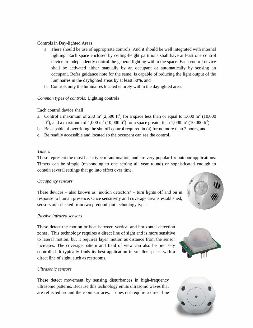
Controls in Day-lighted Areas
a. There should be use of appropriate controls. And it should be well integrated with internal
lighting. Each space enclosed by ceiling-height partitions shall have at least one control
device to independently control the general lighting within the space. Each control device
shall be activated either manually by an occupant or automatically by sensing an
occupant. Refer guidance note for the same. Is capable of reducing the light output of the
luminaires in the daylighted areas by at least 50%, and
b. Controls only the luminaires located entirely within the daylighted area.
Common types of controls: Lighting controls
Each control device shall
a. Control a maximum of 250 m2
(2,500 ft2) for a space less than or equal to 1,000 m
2 (10,000
ft2), and a maximum of 1,000 m
2 (10,000 ft
2) for a space greater than 1,000 m
2 (10,000 ft
2).
b. Be capable of overriding the shutoff control required in (a) for no more than 2 hours, and
c. Be readily accessible and located so the occupant can see the control.
Timers
These represent the most basic type of automation, and are very popular for outdoor applications.
Timers can be simple (responding to one setting all year round) or sophisticated enough to
contain several settings that go into effect over time.
Occupancy sensors
These devices – also known as ‗motion detectors‘ – turn lights off and on in
response to human presence. Once sensitivity and coverage area is established,
sensors are selected from two predominant technology types.
Passive infrared sensors
These detect the motion or heat between vertical and horizontal detection
zones. This technology requires a direct line of sight and is more sensitive
to lateral motion, but it requires layer motion as distance from the sensor
increases. The coverage pattern and field of view can also be precisely
controlled. It typically finds its best application in smaller spaces with a
direct line of sight, such as restrooms.
Ultrasonic sensors
These detect movement by sensing disturbances in high-frequency
ultrasonic patterns. Because this technology emits ultrasonic waves that
are reflected around the room surfaces, it does not require a direct line

of sight. It is more sensitive to motion towards and away from the sensor and its sensitivity
decreases relative to its distances from the sensor. It also does not have a definable coverage
pattern or field of view. These characteristics make it suitable for use in layer-enclosed areas that
may have cabinets, shelving, partitions, or other obstructions. If necessary, these technologies can
also be combined into one product to improve detection and reduce the likelihood of triggering a
false on or off mode.
Photocells
These measure the amount of natural light available and suitable for both indoor and outdoor
applications. When available light falls below a specified level, a control unit switches the lights
on (or adjusts a driver to provide more light). Photocells can be programmed so that lights do not
flip on and off on partially cloudy days.
In conclusion one can say that a lighting scheme is optimized when it is effective and at the same
time efficient also.
2. Efficiency of lighting scheme
How to design an optimized lighting scheme?
To design an optimized lighting scheme one should follow the following steps –
1. Select lamps, luminaires and control gears which are efficient –
Efficiency of lamps - Efficiency of lamp is defined by the term efficacy which means the
amount of lumen produced by the lamp per unit wattage. Higher the efficacy of the lamp
better it is. Also the CRI value of the lamps selected must be in accordance with the
application for which it is going to be used. For example in an office space or a display area
of a commercial complex one will require lamps with CRI values which will give a very near
to the realistic view but on the other hand in case of a street light the CRI will not be the
guiding factor in selection of lamp.
High efficacy Lamps
Lamp efficacy, in an interior lighting scheme, plays a very crucial role. A lighting scheme which
utilizes lamps with lower efficacies will result in increased number of lamps and hence increase
the LPD (lighting power density) of a space. The increased LPD will not only increase the
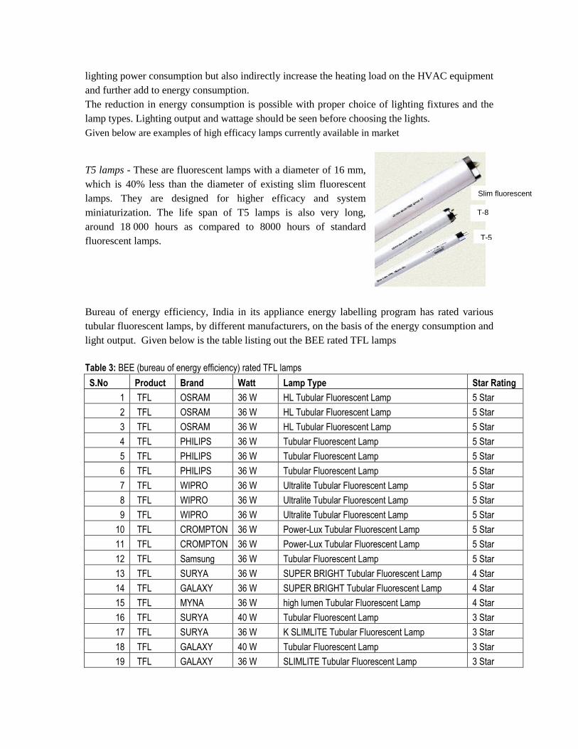
Slim fluorescent
lamps (T12)
T-5
T-8
lighting power consumption but also indirectly increase the heating load on the HVAC equipment
and further add to energy consumption.
The reduction in energy consumption is possible with proper choice of lighting fixtures and the
lamp types. Lighting output and wattage should be seen before choosing the lights.
Given below are examples of high efficacy lamps currently available in market
T5 lamps - These are fluorescent lamps with a diameter of 16 mm,
which is 40% less than the diameter of existing slim fluorescent
lamps. They are designed for higher efficacy and system
miniaturization. The life span of T5 lamps is also very long,
around 18 000 hours as compared to 8000 hours of standard
fluorescent lamps.
Bureau of energy efficiency, India in its appliance energy labelling program has rated various
tubular fluorescent lamps, by different manufacturers, on the basis of the energy consumption and
light output. Given below is the table listing out the BEE rated TFL lamps
Table 3: BEE (bureau of energy efficiency) rated TFL lamps
S.No Product Brand Watt Lamp Type Star Rating
1 TFL OSRAM 36 W HL Tubular Fluorescent Lamp 5 Star
2 TFL OSRAM 36 W HL Tubular Fluorescent Lamp 5 Star
3 TFL OSRAM 36 W HL Tubular Fluorescent Lamp 5 Star
4 TFL PHILIPS 36 W Tubular Fluorescent Lamp 5 Star
5 TFL PHILIPS 36 W Tubular Fluorescent Lamp 5 Star
6 TFL PHILIPS 36 W Tubular Fluorescent Lamp 5 Star
7 TFL WIPRO 36 W Ultralite Tubular Fluorescent Lamp 5 Star
8 TFL WIPRO 36 W Ultralite Tubular Fluorescent Lamp 5 Star
9 TFL WIPRO 36 W Ultralite Tubular Fluorescent Lamp 5 Star
10 TFL CROMPTON 36 W Power-Lux Tubular Fluorescent Lamp 5 Star
11 TFL CROMPTON 36 W Power-Lux Tubular Fluorescent Lamp 5 Star
12 TFL Samsung 36 W Tubular Fluorescent Lamp 5 Star
13 TFL SURYA 36 W SUPER BRIGHT Tubular Fluorescent Lamp 4 Star
14 TFL GALAXY 36 W SUPER BRIGHT Tubular Fluorescent Lamp 4 Star
15 TFL MYNA 36 W high lumen Tubular Fluorescent Lamp 4 Star
16 TFL SURYA 40 W Tubular Fluorescent Lamp 3 Star
17 TFL SURYA 36 W K SLIMLITE Tubular Fluorescent Lamp 3 Star
18 TFL GALAXY 40 W Tubular Fluorescent Lamp 3 Star
19 TFL GALAXY 36 W SLIMLITE Tubular Fluorescent Lamp 3 Star
20 TFL OSRAM 36 W Tubular Fluorescent Lamp 3 Star
21 TFL OSRAM 40 W OSRAM BASIC PLUS TFL 3 Star
22 TFL OSRAM 40 W Tubular Fluorescent Lamp 3 Star
23 TFL PHILIPS 40 W Tubular Fluorescent Lamp 3 Star
24 TFL PHILIPS 36 W Tubular Fluorescent Lamp 3 Star
25 TFL WIPRO 40 W PREMIUM Tubular Fluorescent Lamp 3 Star
26 TFL WIPRO 36 W SAFELITE Tubular Fluorescent Lamp 3 Star
27 TFL WIPRO 40 W Tubular Fluorescent Lamp 3 Star
28 TFL ANCHOR 40 W Tubular Fluorescent Lamp 3 Star
29 TFL ANCHOR 36 W Tubular Fluorescent Lamp 3 Star
30 TFL CROMPTON 36 W Super Saver Tubular Fluorescent Lamp 3 Star
31 TFL CROMPTON 40 W Brightlux Tubular Fluorescent Lamp 3 Star
32 TFL CROMPTON 40 W Tubular Fluorescent Lamp 3 Star
33 TFL BAJAJ 40 W Cool Day Light Tubular Fluorescent Lamp 3 Star
34 TFL BAJAJ 36 W Tubular Fluorescent Lamp 3 Star
35 TFL HIND 40 W Cool Day Light Tubular Fluorescent Lamp 3 Star
36 TFL HIND 36 W Cool Day Light Tubular Fluorescent Lamp 3 Star
37 TFL MYNA 40 W Tubular Fluorescent Lamp 3 Star
38 TFL MYNA 36 W Tubular Fluorescent Lamp 3 Star
39 TFL GE 36 W GE SLENDER TFL 3 Star
40 TFL GE 40 W GE Standard TFL 3 Star
41 TFL CEMA 36 W CEMA Energy Saver 3 Star
42 TFL CEMA 40 W CEMA TC 3 3 Star
43 TFL Samsung 40 W Tubular Fluorescent Lamp 3 Star
44 TFL ONIDA 36 W Tubular Fluorescent Lamp 3 Star
45 TFL ONIDA 40 W Tubular Fluorescent Lamp 3 Star
46 TFL ECOLITE 40 W Tubular Fluorescent Lamp 3 Star
47 TFL ECOLITE 36 W Tubular Fluorescent Lamp 3 Star
48 TFL JINDAL 40 W Cool Day Light Tubular Fluorescent Lamp 3 Star
49 TFL PHILIPS 40 W Tubular Fluorescent Lamp 2 Star
Compact Fluorescent lamps - CFLs (Compact fluorescent
lamps) produce light in the same manner as linear fluorescent
lamp. Their tube diameter is usually 5/8 inch (T5) or smaller.
CFL power is 5-55W. Typical CFLs have been presented in
figure
Light emitting diodes
LEDs are small in size but can be grouped together for higher
intensity. The efficacy of a typical residential application LED is
approximately 20 lumens per watt though 100 lumens per watt
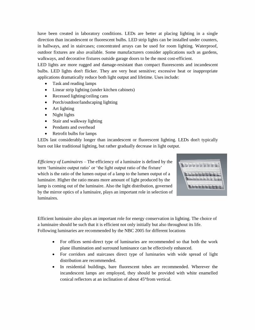
have been created in laboratory conditions. LEDs are better at placing lighting in a single
direction than incandescent or fluorescent bulbs. LED strip lights can be installed under counters,
in hallways, and in staircases; concentrated arrays can be used for room lighting. Waterproof,
outdoor fixtures are also available. Some manufacturers consider applications such as gardens,
walkways, and decorative fixtures outside garage doors to be the most cost-efficient.
LED lights are more rugged and damage-resistant than compact fluorescents and incandescent
bulbs. LED lights don't flicker. They are very heat sensitive; excessive heat or inappropriate
applications dramatically reduce both light output and lifetime. Uses include:
Task and reading lamps
Linear strip lighting (under kitchen cabinets)
Recessed lighting/ceiling cans
Porch/outdoor/landscaping lighting
Art lighting
Night lights
Stair and walkway lighting
Pendants and overhead
Retrofit bulbs for lamps
LEDs last considerably longer than incandescent or fluorescent lighting. LEDs don't typically
burn out like traditional lighting, but rather gradually decrease in light output.
Efficiency of Luminaires – The efficiency of a luminaire is defined by the
term ‗luminaire output ratio‘ or ‗the light output ratio of the fixture‘
which is the ratio of the lumen output of a lamp to the lumen output of a
luminaire. Higher the ratio means more amount of light produced by the
lamp is coming out of the luminaire. Also the light distribution, governed
by the mirror optics of a luminaire, plays an important role in selection of
luminaires.
Efficient luminaire also plays an important role for energy conservation in lighting. The choice of
a luminaire should be such that it is efficient not only initially but also throughout its life.
Following luminaries are recommended by the NBC 2005 for different locations
For offices semi-direct type of luminaries are recommended so that both the work
plane illumination and surround luminance can be effectively enhanced.
For corridors and staircases direct type of luminaries with wide spread of light
distribution are recommended.
In residential buildings, bare fluorescent tubes are recommended. Wherever the
incandescent lamps are employed, they should be provided with white enamelled
conical reflectors at an inclination of about 45°from vertical.
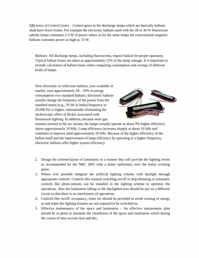
Efficiency of Control Gears – Control gears in the discharge lamps which are basically ballasts
shall have lower losses. For example the electronic ballasts used with the 28 or 36 W fluorescent
tubular lamps consumes 2-3 W of power where as for the same lamps the conventional magnetic
ballasts consumes power as high as 15 W.
Ballasts- All discharge lamps, including fluorescents, require ballast for proper operation.
Typical ballast losses are taken as approximately 15% of the lamp wattage. It is important to
include calculation of ballast losses when comparing consumption and savings of different
kinds of lamps.
New electronic or solid state ballasts, now available in
market, save approximately 20—30% in energy
consumption over standard ballasts. Electronic ballasts
usually change the frequency of the power from the
standard mains (e.g., 50 Hz in India) frequency to
20,000 Hz or higher, substantially eliminating the
stroboscopic effect of flicker associated with
fluorescent lighting. In addition, because more gas
remains ionized in the arc stream, the lamps actually operate at about 9% higher efficiency
above approximately 10 kHz. Lamp efficiency increases sharply at about 10 kHz and
continues to improve until approximately 20 kHz. Because of the higher efficiency of the
ballast itself and the improvement of lamp efficiency by operating at a higher frequency,
electronic ballasts offer higher system efficiency.
2. Design the scheme/layout of luminaires in a manner that will provide the lighting levels
as recommended by the NBC 2005 with a better uniformity over the entire working
plane.
3. Where ever possible integrate the artificial lighting scheme with daylight through
appropriate controls. Controls like manual switching on/off or step-dimming or automatic
controls like photo-sensors can be installed in the lighting scheme to optimize the
operations. Also the luminaires falling in the daylighted area should be put on a different
circuit so that there is no interference of operations.
4. Controls like on/off, occupancy, timer etc should be provided to avoid wasting of energy
as and when the lighting fixtures are not required to be switched on.
5. Effective maintenance of the space and luminaires – An effective maintenance plan
should be in place to maintain the cleanliness of the space and luminaires which during
the course of time accrete dust and dirt.
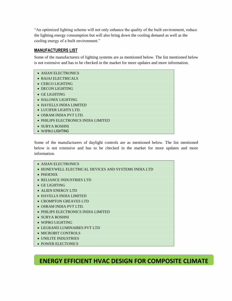
―An optimized lighting scheme will not only enhance the quality of the built environment, reduce
the lighting energy consumption but will also bring down the cooling demand as well as the
cooling energy of a built environment.‖
MANUFACTURERS LIST
Some of the manufacturers of lighting systems are as mentioned below. The list mentioned below
is not extensive and has to be checked in the market for more updates and more information.
ASIAN ELECTRONICS
BAJAJ ELECTRICALS
CERCO LIGHTING
DECON LIGHTING
GE LIGHTING
HALONIX LIGHTING
HAVELLS INDIA LIMITED
LUCIFER LIGHTS LTD.
OSRAM INDIA PVT LTD.
PHILIPS ELECTRONICS INDIA LIMITED
SURYA ROSHNI
WIPRO LIGHTING
Some of the manufacturers of daylight controls are as mentioned below. The list mentioned
below is not extensive and has to be checked in the market for more updates and more
information.
ASIAN ELECTRONICS
HONEYWELL ELECTRICAL DEVICES AND SYSTEMS INDIA LTD
PHOENIX
RELIANCE INDUSTRIES LTD
GE LIGHTING
ALIEN ENERGY LTD
HAVELLS INDIA LIMITED
CROMPTON GREAVES LTD
OSRAM INDIA PVT LTD.
PHILIPS ELECTRONICS INDIA LIMITED
SURYA ROSHNI
WIPRO LIGHTING
LEGRAND LUMINAIRES PVT LTD
MICROBIT CONTROLS
UNILITE INDUSTRIES
POWER ELECTONICS
ENERGY EFFICIENT HVAC DESIGN FOR COMPOSITE CLIMATE

Overview of Design Conditions:
Air conditioning system consumes most of the energy that a building needs in its
operation. In order to reduce energy consumption in air conditioning effort should be
made as per the following steps:
1. Reduce dependence on air conditioning system in the building while designing. 2. Recognise spaces inside the building which do not require air conditioning, as
reduction in air conditioned spaces will reduce AC consumption load and energy needed for the same.
3. Optimise cooling load by selecting inside design conditions and outdoor design conditions specified in National Building Code of India 2005.
Indoor design conditions
Inside design conditions for air conditioned spaces for various types of spaces:
S. No. Category Inside Design Conditions
(I) Restaurants DB 23 to 26 °C RH 55 to 60%
(ii) Office Buildings DB 23 to 26 °C RH 55 to 60%
(iii) Radio and Television Studios DB 23 to 26 °C RH 45 to 55%
(iv) Departmental Stores DB 23 to 26 °C RH 50 to 60%
(v) Hotel Guest Rooms DB 23 to 26 °C RH 50 to 60%
(vi) Class Room DB 23 to 26 °C RH 50 to 60%
(vii) Auditoriums DB 23 to 26 °C RH 50 to 60%
(viii) Recovery Rooms DB 24 to 26 °C RH 45 to 55 %
(ix) Patient Rooms DB 24 to 26 °C RH 45 to 55 %
(x) Operation Theatres DB 17 to 27 °C RH 45 to 55 %
(xi) Museums and libraries DB 20 to 22 °C RH 40 to 55 %
(xii) Telephone Terminal Rooms DB 22 to 26 °C RH 40 to 50 %
* DB: Dry bulb temperature, RH: Relative humidity
Outdoor design conditions:
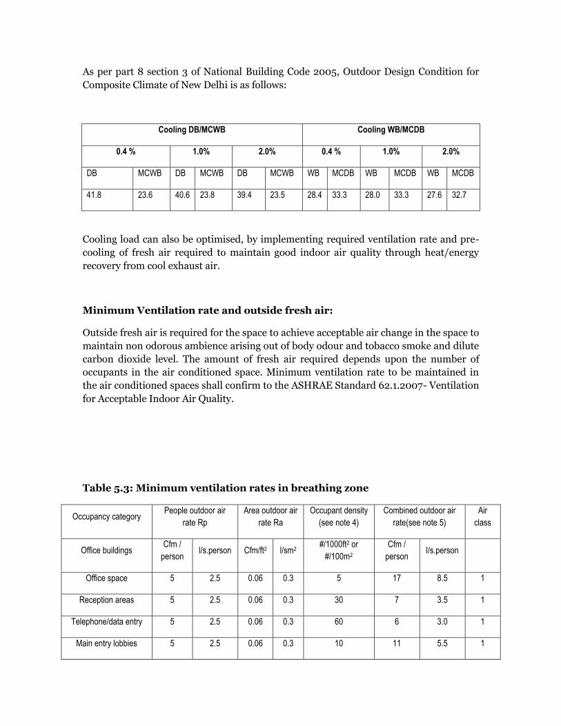
As per part 8 section 3 of National Building Code 2005, Outdoor Design Condition for
Composite Climate of New Delhi is as follows:
Cooling DB/MCWB Cooling WB/MCDB
0.4 % 1.0% 2.0% 0.4 % 1.0% 2.0%
DB MCWB DB MCWB DB MCWB WB MCDB WB MCDB WB MCDB
41.8 23.6 40.6 23.8 39.4 23.5 28.4 33.3 28.0 33.3 27.6 32.7
Cooling load can also be optimised, by implementing required ventilation rate and pre-
cooling of fresh air required to maintain good indoor air quality through heat/energy
recovery from cool exhaust air.
Minimum Ventilation rate and outside fresh air:
Outside fresh air is required for the space to achieve acceptable air change in the space to
maintain non odorous ambience arising out of body odour and tobacco smoke and dilute
carbon dioxide level. The amount of fresh air required depends upon the number of
occupants in the air conditioned space. Minimum ventilation rate to be maintained in
the air conditioned spaces shall confirm to the ASHRAE Standard 62.1.2007- Ventilation
for Acceptable Indoor Air Quality.
Table 5.3: Minimum ventilation rates in breathing zone
Occupancy category People outdoor air
rate Rp
Area outdoor air
rate Ra
Occupant density
(see note 4)
Combined outdoor air
rate(see note 5)
Air
class
Office buildings Cfm /
person l/s.person Cfm/ft2 l/sm2
#/1000ft2 or
#/100m2
Cfm /
person l/s.person
Office space 5 2.5 0.06 0.3 5 17 8.5 1
Reception areas 5 2.5 0.06 0.3 30 7 3.5 1
Telephone/data entry 5 2.5 0.06 0.3 60 6 3.0 1
Main entry lobbies 5 2.5 0.06 0.3 10 11 5.5 1
Air Handling Units (AHU) and its specifications to achieve
Energy Efficiency:
Air Handling Units:
An air handler, or air handling unit (often abbreviated to AHU), is a device used to
condition and circulate air as part of a heating, ventilating, and air-conditioning (HVAC
system.
Components: An air handler is a large metal box containing a blower, heating and/or
cooling elements filter racks or chambers, sound attenuators, and dampers. Air handlers
usually connect to ductwork that distributes the conditioned air through the building,
and returns it to the AHU.
AHU are used to cool larger areas and their cooling capacity varies from 5-30 tons. The
chilled water from central plant is passed through the cooling coil present in the AHU.
Air from the room returns to the AHUs either through the ceiling or return ducts and
passes through the filters where dust particles are arrested and removed. Then it is
passed over the coil where it loses its heat and the cool air is then supplied to the room
through a duct by a draw through fan kept in the AHU. Two types of air handling units
are available:
1. Constant air volume In the constant air volume, the circulating air volume remains constant or the
blower fan is of constant speed and fluctuations in the cooling demand are
controlled by variation in the flow of chilled water in the cooling coil.
2. Variable air volume In the variable air volume type, the airflow can be varied using controls to meet
the cooling demand of different rooms.
Energy Efficiency through AHU:
Energy saving potential can be maximised in air conditioning system by employing
following features in the air handling units:
1. Air system design shall be equipped to operate in 100% fresh air mode. 2. Free cooling mode 3. AHU minimum fan efficiency 4. Energy saving through efficient motors
1. Air system design shall be equipped to operate in 100% fresh air mode. Heat usually builds up in building when air conditioning system is not working
during non-working hours, weekends and holidays. This heat build-up affects the
following day operation of air conditioning system by increasing the cooling
demand; thus energy consumption goes high. IN order to remove this heat
everyday night, flushing out air is needed. In this regard, the outdoor fresh air
intake is important as its cooler in comparison to the zone air. Thus the AHUs
supply this outdoor fresh air and helps in flushing out this heat build up. In order
to maximise the effectiveness of the air flushing; all AHUs should be designed so
that it operates at 100% fresh air mode to remove the heat.
2. Air-side economizers Energy can be saved in buildings by using cool outside air as a means of cooling
the indoor space. When the enthalpy of the outside air is less than the enthalpy of
the re-circulated air, conditioning the outside air is more energy efficient than
conditioning re-circulated air. When the outside air is sufficiently cool, it doesn’t
require additional conditioning; this portion of the air-side economizer control
scheme is called free cooling. Air-side economizers can reduce HVAC energy
costs and should be designed in accordance with ASHRAE 90.1.2007.
Design capacity
Air economizer systems shall be capable of modulating outdoor air and return air
dampers to provide up to 100% of the design supply air quantity as outdoor air
for cooling
Control signal
Economizer dampers shall be capable of being sequenced with the mechanical
cooling equipment and shall not be controlled by only mixed air temperature.
However, the use of mixed air temperature limit control shall be permitted for
the systems controlled from space temperature e.g., single-zone systems
High-limit shutoff
All air economizers shall be capable of automatically reducing outdoor air intake
to the design minimum outdoor air quantity when outdoor air intake will no
longer reduce cooling energy usage. The high-limit shutoff control types and
settings for those controls shall be as recommended in ASHRAE standard
90.1.2007.
3. AHUs should be equipped to vary the supply air capacity All AHUs are designed for peak load condition but mostly operates at part load
conditions. This operating capacity of the AHUs when un-synchronized with the
cooling demand, lead to over cooling of space which ends with discomfort and
energy wastage. In comfort cooling, AHUs supply air at constant air volume;
hence fan operates as constant speed.
In order to control the part load capacity two methods are employed:
Increasing the supply air temperature by varying the chilled water flow in coil with same air quantity or
Varying the air quantity but keeping the supply air temperature same.
However, it has been observed that the best comfort conditions can be provided if
AHUs have provision for both.
Recommendations:
It is recommended that AHUs shall have provision to vary supply air quantity in
response to the varying cooling demand with a minimum supply air capacity up
to 50% of the design supply air capacity. This can be achieved by installing
variable frequency drives on constant speed fans fitted in AHUs.
Variable frequency drives:
These are devices used for varying the speed of fans to exactly match the supply
air quantity needed to provide required cooling in the conditioned space. A VFD
consists of an input rectifier (which converts AC to DC) followed by an inverter
(that inverts DC to AC) connected through a DC intermediate voltage link and
operates in response to the return air temperature.
4. AHU minimum fan efficiency The energy consuming component in AHUs is fan and fan efficiency plays an
important role in enhancing overall efficiency of the air conditioning systems.
Forward curved, backward curved or radial types of centrifugal fans are generally
used in AHUs. For fans less than 6 bhp (break horse power) the fan efficiency

shall not be less than 65% and fans 6bhp and larger the fan efficiency shall not be
less than 80%.
5. Pre-cooling of fresh air required for maintaining good indoor air quality: Outdoor fresh air requirement is required to maintain an acceptable indoor air
quality. In general, the temperature of outdoor air is at higher temperature in
compared to the return air from the space, which increases the cooling load of the
space. Therefore, pre cooling of outdoor fresh air is needed before it mixes with
return air, thereby reducing its impact on cooling load and energy consumption of air
conditioned space. This pre-cooling of the fresh air can be done with the help of
Energy Recovery Wheel (ERV)
Energy Recovery Wheel
When a unit is equipped with an optional enthalpy wheel, energy recovery is
provided by drawing outside air across half of the enthalpy wheel and drawing
exhaust air across the other half. Latent heat and sensible heat are transferred from
the hotter and moist exhaust air to the colder and dry outside air during winter
conditions. Latent heat and sensible heat are transferred from the hotter and moist
outside air to the cooler and dry exhaust air during summer conditions. Energy
recovery control consists of starting and stopping an exhaust fan, modulating the
speed of the exhaust fan, starting and stopping an enthalpy wheel, optionally
controlling the speed of the enthalpy wheel and opening and closing a set of bypass
dampers. The outdoor dampers are controlled in the normal manner.
6. Energy saving through efficient motors
2 poles & 4 poles, 3 phase squirrel cage induction motors are generally used in air
conditioning systems. The minimum efficiency of motors shall be in compliance with
nominal efficiency of eff-1 type mentioned in Table 1 & Table 2 for 2 poles & 4 poles
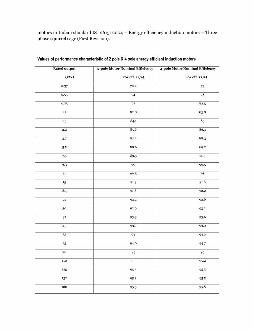
motors in Indian standard IS 12615: 2004 – Energy efficiency induction motors – Three
phase squirrel cage (First Revision).
Values of performance characteristic of 2 pole & 4 pole energy efficient induction motors
Rated output
(kW)
2-pole Motor Nominal Efficiency
For eff. 1 (%)
4-pole Motor Nominal Efficiency
For eff. 1 (%)
0.37 70.2 73
0.55 74 78
0.75 77 82.5
1.1 82.8 83.8
1.5 84.1 85
2.2 85.6 86.4
3.7 87.5 88.3
5.5 88.6 89.2
7.5 89.5 90.1
9.3 90 90.5
11 90.5 91
15 91.3 91.8
18.5 91.8 92.2
22 92.2 92.6
30 92.9 93.2
37 93.3 93.6
45 93.7 93.9
55 94 94.2
75 94.6 94.7
90 95 95
110 95 95.2
125 95.3 95.5
132 95.3 95.5
160 95.5 95.8

Chillers and guidelines for energy efficiency:
Chiller
It’s a device that removes heat from a liquid via a
vapour-compression or absorption refrigeration
cycle. This cooled liquid flows through pipes in a
building and passes through coils in air handlers,
fan-coil units, or other systems, cooling and
usually dehumidifying the air in the building.
Chillers are of two types; an air-cooled or water-
cooled.
Air-cooled chillers are usually outside and
consist of condenser coils cooled by fan-driven
air.
Water-cooled chillers are usually inside a
building, and heat from these chillers is carried
by re-circulating water to outdoor cooling towers. A vapour-compression water chiller
comprises the four major components of the vapour-compression refrigeration cycle -
compressor, evaporator, condenser, and some form of metering device.
Energy Efficiency:
Energy efficiency in air conditioning system can be achieved by employing the following
measures for chiller efficiency:
1. Chiller efficiency as per ECBC recommendations 2. Chilled water supply temperature 3. Chilled water flow rate. 4. BEE Star rated Unitary systems
1. Chiller Efficiency as per ECBC Recommendations: In the process of designing the air conditioning system, the chiller selected should follow
the efficiency recommended in Energy Conservation Building Code 2007. It must be
noted that, foot note of ASHRAE 90.1.2007 to be included.
Sources: http://www.treehugger.com
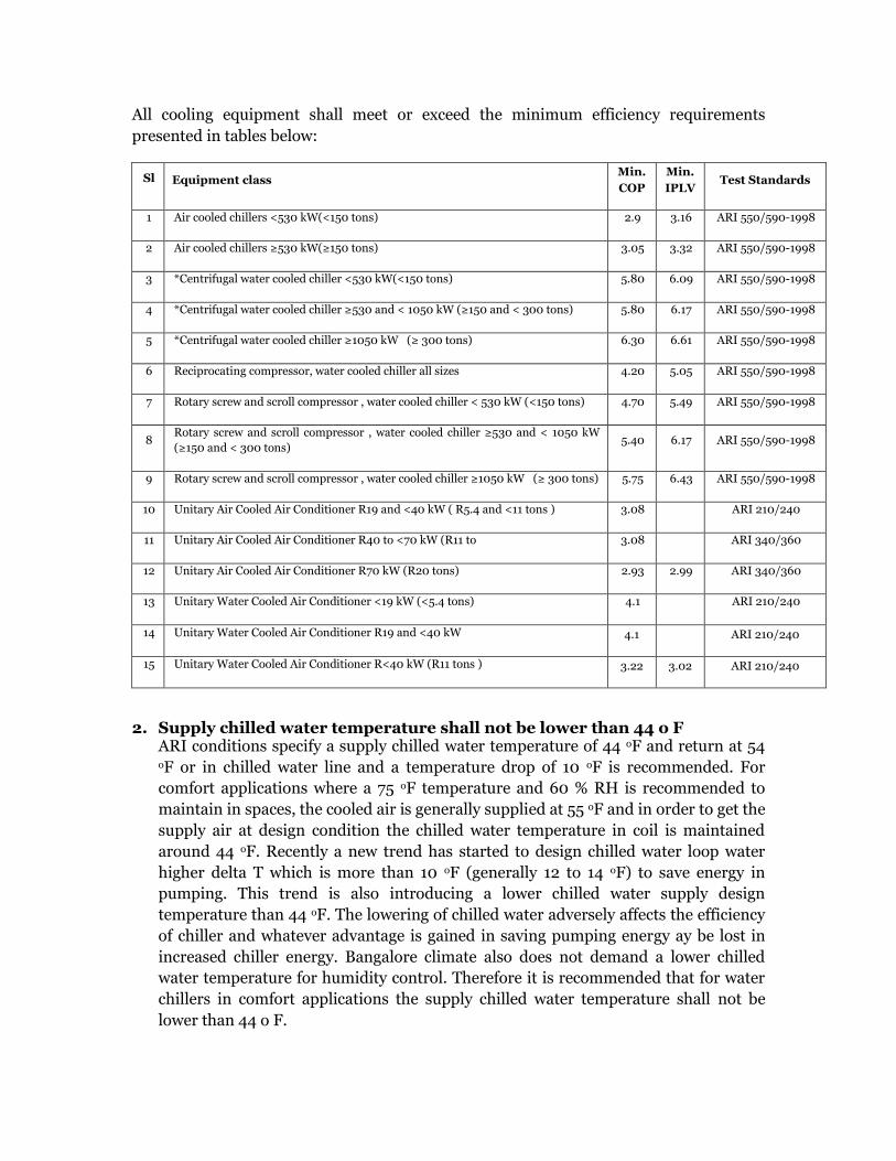
All cooling equipment shall meet or exceed the minimum efficiency requirements
presented in tables below:
Sl Equipment class Min.
COP
Min.
IPLV Test Standards
1 Air cooled chillers <530 kW(<150 tons) 2.9 3.16 ARI 550/590-1998
2 Air cooled chillers ≥530 kW(≥150 tons) 3.05 3.32 ARI 550/590-1998
3 *Centrifugal water cooled chiller <530 kW(<150 tons) 5.80 6.09 ARI 550/590-1998
4 *Centrifugal water cooled chiller ≥530 and < 1050 kW (≥150 and < 300 tons) 5.80 6.17 ARI 550/590-1998
5 *Centrifugal water cooled chiller ≥1050 kW (≥ 300 tons) 6.30 6.61 ARI 550/590-1998
6 Reciprocating compressor, water cooled chiller all sizes 4.20 5.05 ARI 550/590-1998
7 Rotary screw and scroll compressor , water cooled chiller < 530 kW (<150 tons) 4.70 5.49 ARI 550/590-1998
8 Rotary screw and scroll compressor , water cooled chiller ≥530 and < 1050 kW
(≥150 and < 300 tons) 5.40 6.17 ARI 550/590-1998
9 Rotary screw and scroll compressor , water cooled chiller ≥1050 kW (≥ 300 tons) 5.75 6.43 ARI 550/590-1998
10 Unitary Air Cooled Air Conditioner R19 and <40 kW ( R5.4 and <11 tons ) 3.08 ARI 210/240
11 Unitary Air Cooled Air Conditioner R40 to <70 kW (R11 to 3.08 ARI 340/360
12 Unitary Air Cooled Air Conditioner R70 kW (R20 tons) 2.93 2.99 ARI 340/360
13 Unitary Water Cooled Air Conditioner <19 kW (<5.4 tons) 4.1 ARI 210/240
14 Unitary Water Cooled Air Conditioner R19 and <40 kW 4.1 ARI 210/240
15 Unitary Water Cooled Air Conditioner R<40 kW (R11 tons ) 3.22 3.02 ARI 210/240
2. Supply chilled water temperature shall not be lower than 44 o F ARI conditions specify a supply chilled water temperature of 44 oF and return at 54 oF or in chilled water line and a temperature drop of 10 oF is recommended. For
comfort applications where a 75 oF temperature and 60 % RH is recommended to
maintain in spaces, the cooled air is generally supplied at 55 oF and in order to get the
supply air at design condition the chilled water temperature in coil is maintained
around 44 oF. Recently a new trend has started to design chilled water loop water
higher delta T which is more than 10 oF (generally 12 to 14 oF) to save energy in
pumping. This trend is also introducing a lower chilled water supply design
temperature than 44 oF. The lowering of chilled water adversely affects the efficiency
of chiller and whatever advantage is gained in saving pumping energy ay be lost in
increased chiller energy. Bangalore climate also does not demand a lower chilled
water temperature for humidity control. Therefore it is recommended that for water
chillers in comfort applications the supply chilled water temperature shall not be
lower than 44 o F.
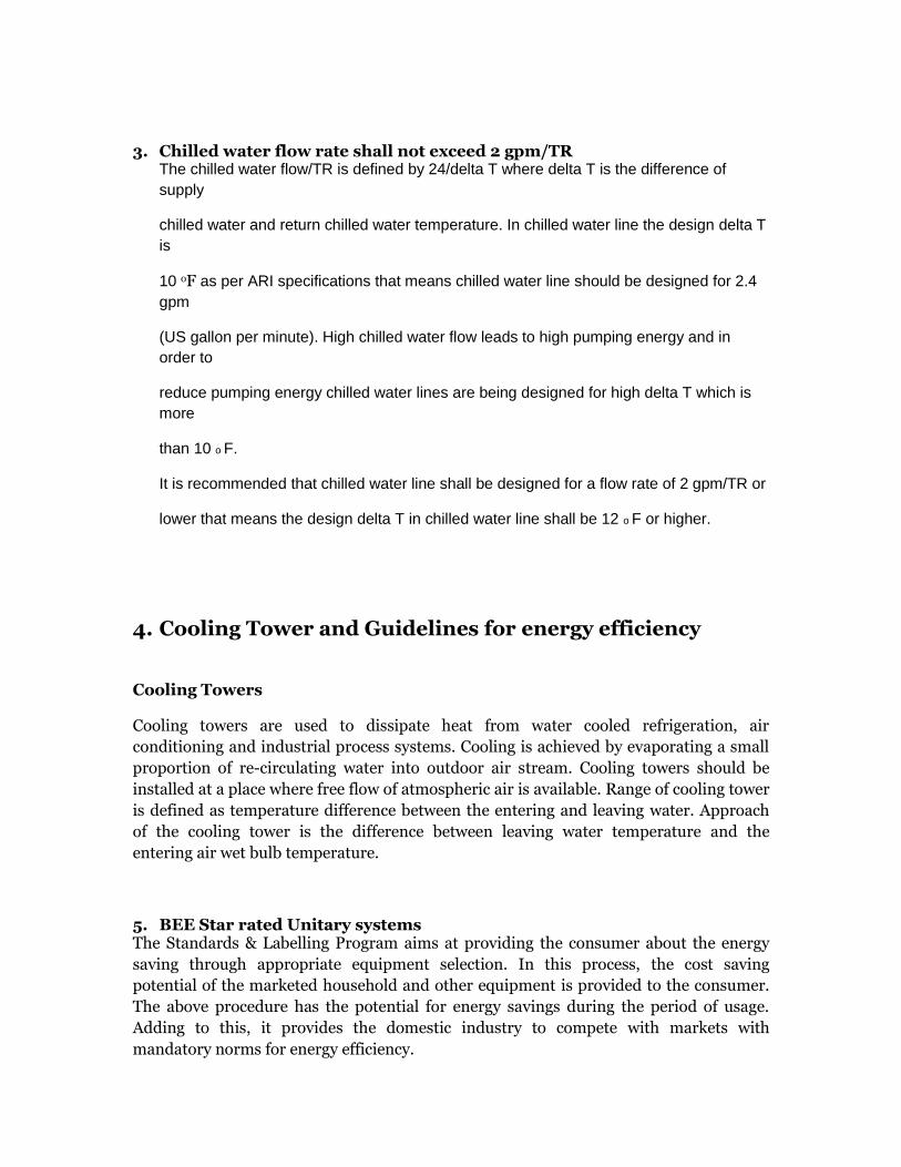
3. Chilled water flow rate shall not exceed 2 gpm/TR The chilled water flow/TR is defined by 24/delta T where delta T is the difference of
supply
chilled water and return chilled water temperature. In chilled water line the design delta T
is
10 oF as per ARI specifications that means chilled water line should be designed for 2.4
gpm
(US gallon per minute). High chilled water flow leads to high pumping energy and in
order to
reduce pumping energy chilled water lines are being designed for high delta T which is
more
than 10 o F.
It is recommended that chilled water line shall be designed for a flow rate of 2 gpm/TR or
lower that means the design delta T in chilled water line shall be 12 o F or higher.
4. Cooling Tower and Guidelines for energy efficiency
Cooling Towers
Cooling towers are used to dissipate heat from water cooled refrigeration, air
conditioning and industrial process systems. Cooling is achieved by evaporating a small
proportion of re-circulating water into outdoor air stream. Cooling towers should be
installed at a place where free flow of atmospheric air is available. Range of cooling tower
is defined as temperature difference between the entering and leaving water. Approach
of the cooling tower is the difference between leaving water temperature and the
entering air wet bulb temperature.
5. BEE Star rated Unitary systems The Standards & Labelling Program aims at providing the consumer about the energy
saving through appropriate equipment selection. In this process, the cost saving
potential of the marketed household and other equipment is provided to the consumer.
The above procedure has the potential for energy savings during the period of usage.
Adding to this, it provides the domestic industry to compete with markets with
mandatory norms for energy efficiency.
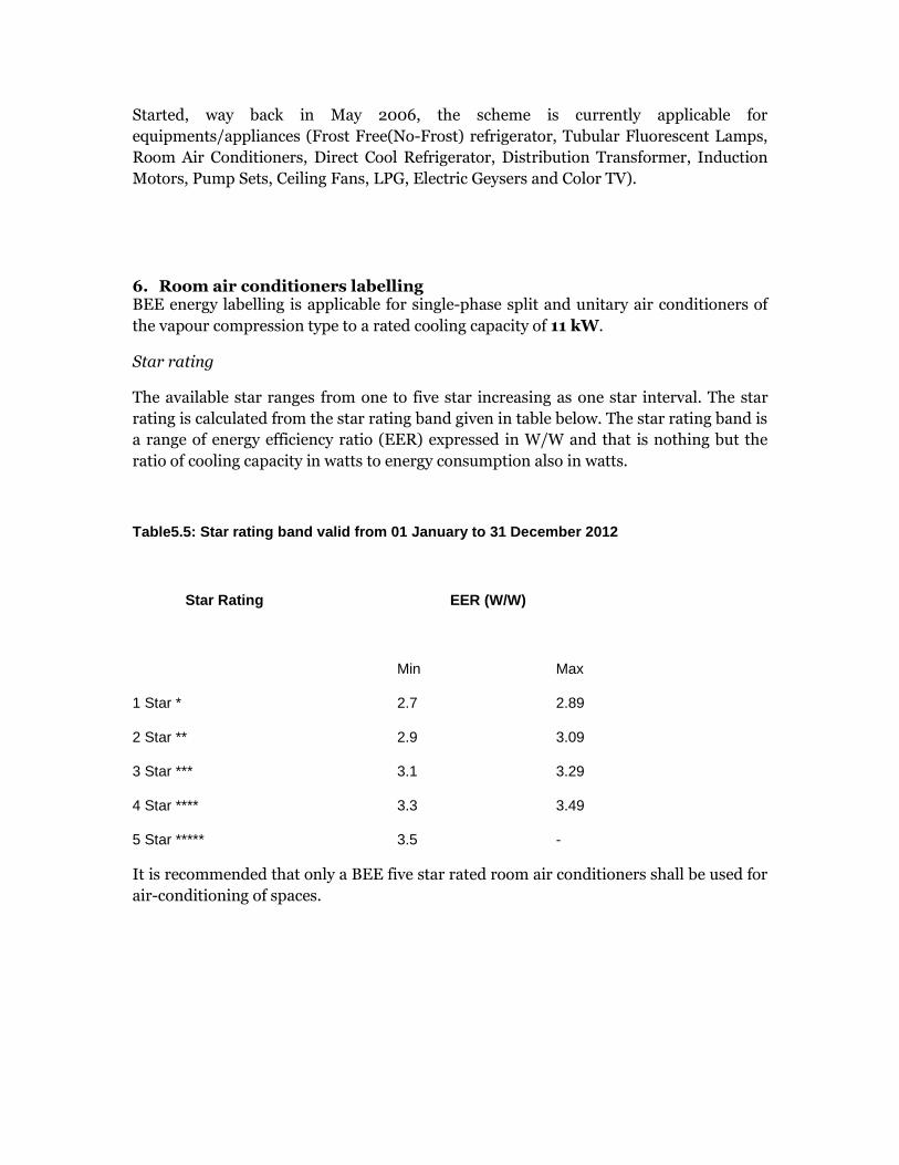
Started, way back in May 2006, the scheme is currently applicable for
equipments/appliances (Frost Free(No-Frost) refrigerator, Tubular Fluorescent Lamps,
Room Air Conditioners, Direct Cool Refrigerator, Distribution Transformer, Induction
Motors, Pump Sets, Ceiling Fans, LPG, Electric Geysers and Color TV).
6. Room air conditioners labelling BEE energy labelling is applicable for single-phase split and unitary air conditioners of
the vapour compression type to a rated cooling capacity of 11 kW.
Star rating
The available star ranges from one to five star increasing as one star interval. The star
rating is calculated from the star rating band given in table below. The star rating band is
a range of energy efficiency ratio (EER) expressed in W/W and that is nothing but the
ratio of cooling capacity in watts to energy consumption also in watts.
Table5.5: Star rating band valid from 01 January to 31 December 2012
Star Rating EER (W/W)
Min Max
1 Star * 2.7 2.89
2 Star ** 2.9 3.09
3 Star *** 3.1 3.29
4 Star **** 3.3 3.49
5 Star ***** 3.5 -
It is recommended that only a BEE five star rated room air conditioners shall be used for
air-conditioning of spaces.