Embed Size (px)
Citation preview
Fluorescence image courtesy Dr. David Rapaport, UCSD; echelle spectra, courtesy Catalina Scientific; astro image courtesy Adam Block.
High Performance Cooled CCD Camera Systems
2011
151 N. SunriseAve., Ste 902Roseville CA 95661 USA
tel 916 218 7450fax 916 218 7451
www.ccd.com

VALUE
EASE OF INTEGRATION
QUALITY
CUSTOMIZATION
We supply the best price/performance in the industry. Researchers rely on Apogee to provide excellent value for their investment. OEMs rely on Apogee Imaging Systems to deliver ultra-reliable products on time and with consistently high quality. Please contact our sales team for a quotation for any quantity, large or small.
All of our systems run on a single universal software driver. If you integrate control of one Apogee system into a custom software environment, you automatically have support for any of our systems. Based on the feedback we get from our customers, integration is simple and straightforward. We offer an ActiveX driver for Windows environments. Our Linux driver and source are posted on sourceforge. We also offer a Mac OSX driver.
Our goal is steady refinement in every aspect of our cameras, including
product consistency, product lifetimes, ease of adaptation and use, and added hardware and software features. We also continue to refine our procedures, documentation, and customer recordkeeping. We’re proud of the thousands of cameras that we’ve delivered, but even more proud that so little effort is needed to keep them all working. An Apogee camera may become obsolete, but it is extremely unlikely that it will stop working. Your biggest worry: you may wear out an electromechanical shutter every few years. In our effort to improve our process, we’ve achieved the following benchmarks:· FCC compliance· CE compliance· ROHS compliance· ISO-9000 compliance (in process)
Perhaps you need to incorporate custom optical elements into your camera. Apogee Imaging Systems has a long history of working with customers to modify our product line to fit their requirements. Let us know how we can optimize our cameras to best suit your application.
DIVERSITY ADDS STRENGTH
Since 1993, Apogee Imaging Systems (formerly Apogee Instruments) has
been manufacturing cooled CCD cameras for scientific applications. Our cameras are now used in more than 50 countries, from government and private research laboratories to the best of world-class professional observatories. Apogee cameras have been used for a wide variety of applications, including spectroscopic analysis of water, soil, and gems; detection of anthrax; development of methods and technologies for detection of land mines and improvised explosive devices (IEDs); analysis and detection of contaminants at nuclear reactors; imaging of fingerprints without chemicals; x-ray inspection of car parts; fluorescent imaging of cell tissues and microtitre plates; munitions testing; laser beam profiling; poacher surveillance; radiotherapy dosimetry; retinal imaging; mammography; optics testing; discovery of thousands of astronomical objects; and radiometry of a wide variety of light sources. By expanding into broad markets with diverse demands, Apogee has had to develop a wide variety of technologies to solve our customers’ problems. Our astronomy and spectroscopy customers demand low noise, high sensitivity, and high quantitative accuracy. Our life science customers demand speed and ease of use. All customers groups are constantly pushing for higher performance at lower prices.
HIGH PERFORMANCECOOLED CCD CAMERAS
SYSTEM OVERVIEW
©2011 Apogee Imaging Systems Inc. Alta and Ascent are registered trademarks of Apogee Imaging Systems Inc.
Specifications subject to change without notice.
Apogee Alta® and Ascent® cameras are designed for a wide range of demanding
scientific applications. In Ascent, we reduced the size and cost
of our electronics and housings, while at the same time maintaining the key features of our popular Alta Series cameras. We added high-speed 16-bit electronics and some new sensors with resolutions up to 16 megapixels.
The larger Alta cameras offer lower noise and deeper cooling than the Ascent cameras. They also support a broad selection of CCDs, from interlines to full frame front-illuminated to back-illuminated, from large pixels with exceptionally high dynamic range, to very high resolution. You can also choose from a broad selection of housings, from our standard housing, to one with deep cooling, or a short back focal distance (low profile), or a wide entrance aperture (wide angle). Most models are available with either fan or liquid circulation methods for removing heat from the back of the camera.
For both camera series, the direct USB 2.0 link between camera and computer allows easy installation, portability and fast data transfer rate. Ascent maintains compatibility with our Alta ActiveX drivers, as well as Linux and Mac OS X drivers.

Apogee has collected all of our brochures and mechanical drawings onto an Integration Starter Kit CD, together with software drivers and documentation. Free on request.Pictured below: covers of our astronomy, life sciences, spectroscopy, and OEM brochures, all of which are available for download at www.ccd.com
INTEGRATION CD
©2011 Apogee Imaging Systems Inc. Alta and Ascent are registered trademarks of Apogee Imaging Systems Inc.
Specifications subject to change without notice.
There are many factors to consider when choosing a CCD camera: cost, resolution, speed, noise, cooling, sensitivity, housing size. Other features may contribute to a system’s overall suitability, but most of these features are shared by the Alta® and Ascent®. In general, consider the following key requirements to determine the optimal platform:
Alta:Low readout noiseMaximum cooling
Back-illuminated CCDsVery large format CCDs
Optional ethernet interface
Ascent:Low cost
High speed readoutCompact housing
ADVANCED COOLING
HIGHER THROUGHPUT
LOWER COSTS
COMPACT HOUSING
Many applications require clean, quantitative images, but do not require the ultimate in cooling or low readout noise. The Ascent is an ideal solution for many applications where several thousand dollars may be more important than a few electrons.
Ascent was designed to operate at speeds up to the maximum allowed by USB2. Digitization speed is programmable so you can choose your ideal trade-off between speed and noise. All speeds digitize at a full 16 bits.
LOW READOUT NOISE
BACK-ILLUMINATED CCDs
VERY LARGE FORMAT CCDS
Alta’s readout electronics were designed to minimize readout noise. The higher speed software-selectable 12-bit mode is intended for focussing, and not optimized for low noise.
To maximize heat dissipation, Alta’s large inner chamber, back plate, and heatsinks are machined from a single block of aluminum. The four fans have four programmable speeds.
Back-illuminated CCDs are much more expensive than front illuminated CCDs, so they are chosen when necessary for maximum signal-to-noise under low light conditions. Their higher dark current per square millimeter requires the higher cooling of larger Alta housing.
The Alta platform is available in several housing sizes, accomodating CCDs up to 50mm on a side.
The Ascent’s smaller, more lightweight housing fits in many places that the larger Alta cannot.
ASCENT® versus ALTA® SERIES CAMERAS

Feature Ascent® Alta®
Digitization 16 bit, programmable speed Fast 12 and slower 16 bit
Maximum throughput Up to 16 Mpixels/sec (Note 1) Up to 7 Mpixels/sec (Note 2)
Dual channel interline readout Standard (on applicable CCDs) N/A
Progressive scan for interlines Standard
Video focus mode Standard N/A
Maximum cooling 40C below ambient (Note 2) 70C below ambient (Note 2)
Temperature regulation ± 0.1°C
Programmable gain & offset Standard N/A
USB2 interface Standard
Electromechanical shutter N/A Standard, internal (Note 3)
Programmable fan speed N/A Standard
Field upgradeable firmware Standard
Chamber window Fused silica
Peripheral communications 8 pin mini-DIN connector
General purpose I/O port Standard
Programmable LEDs Standard
Power input 6V 12V
Internal memory 32 Mbytes
Types of CCDs supported Interline CCDs only Back- & Front-Illuminated; Interline
External triggering Standard
Image sequences up to 65535 images
Hardware binning Up to 8 x height of CCD
Subarray readout Standard
TDI readout & Kinetics mode (Note 6) N/A Standard (See note 4)
Back focal distance 0.32” (0.81 cm) 0.69” (17.5mm) and up (Note 2)
C-mount interface (Note 7) Optional, external (Note 5) Standard for D01 & D03 housings
Software universality Standard
Housing size 4.8” x 3.25” x 2.25” 6” x 6” x 2.5” (Note 6)
Warranty (Parts & labor) 2 years
Warranty against condensation Lifetime
The primary differences between the Ascent and Alta Series cameras: Ascent is very compact with much lower costs, much faster digitization, and programmable gain. Alta is larger, with better cooling, and lower noise electronics. See the chart below for an overview of the differences. See camera data sheets to get details of a specific model.
Note 1 Maximum single channel throughput 12.5 MHz; dual channels at 8 megapixels/sec eachNote 2 Varies from model to model.Note 3 Electromechanical shutters are standard for full frame CCDs, and optional for interline CCDs.Note 4 Does not apply to interline CCDs.Note 5 CCDs >1” video format are generally too large for C-mount optics.Note 6 Some housings are larger.
ASCENT® versus ALTA® SERIES CAMERAS

ASCENT® SERIES CAMERAS: 0VERVIEW
PROGRAMMABLE DIGITIZATION
ANTI-REFLECTIVE COATED FUSED SILICA OPTICS
SINGLE 6V POWER SUPPLYAscent camera systems include a 6V international power supply (100V-240V input), but can be operated from a clean 6V source.
COMPACT DESIGNThe Ascent systems are extremely lightweight (0.65 kg) and compact. At 4.7” x 3.2” (11.9 x 8.1 cm) and only 1.3” (3.3 cm) thick with no external electronics, the Ascent is a marvel of compact electronics. The standard back focal distance for all models is about 0.32” (0.8 cm).
PROGRAMMABLE GAIN AND OFFSETAll Ascent models feature programmable gain and bias offset programmable in the analog-to-digital converter.
Unlike previous generations of Apogee cameras with fixed digitization rates for each bit depth, the Ascent® cameras feature programmable readout rates using 16-bit digitization. You can choose the best trade-off between noise and readout speed image-by-image. Some CCDs, like the Kodak interline transfers, can read two channels at up to 8 MHz each, for a total throughput of 16 megapixels per second. Other CCDs, like the Sonys, typically have a single channel maximum throughput rate of 12.5 MHz. See individual camera data sheets for specifics regarding each camera system.
The standard chamber window for the Ascent system is fused silica.
Ascent filter wheels are available for 6-positions for 1” (25mm) filters or 8-position for 1.25” (31mm) filters (shown with optional
Nikon F-mount lens adapter).
ASCENT FILTER WHEEL
ASCENT MODELS (ALL CCDs ARE INTERLINE TRANSFER)
Model CCD* Array Pixels Pixel size(microns)
CCD Size (mm)
Area (mm2)
Diagonal(mm)
Videosize (“)
A340 KAI-0340 684 x 484 313K 7.4 4.8 x 3.6 17.2 6.0 0.37A1050 KAI-1050 1024 x 1024 1.1M 5.5 5.6 x 5.6 34.8 8.3 0.52A2050 KAI-2050 1600 x 1200 1.9M 5.5 8.8 x 6.6 58.1 11.0 0.69A2150 KAI-2150 1920 x 1080 2.1M 5.5 10.6 x 5.9 62.7 12.1 0.76A2000 KAI-2020 1600 x 1200 1.9M 7.4 11.8 x 8.9 105.1 14.8 0.93A4050 KAI-4050 2336 x 1752 4.2M 5.5 11.3 x 11.3 126.9 15.9 1.0A4000 KAI-4022 2048 x 2048 4.2M 7.4 15.2 x 15.2 229.7 21.4 1.34A8050 KAI-8050 3296 x 2472 8.1M 5.5 18.1 x 13.6 246.5 22.7 1.42A16000 KAI-16000 4872 x 3248 15.8M 7.4 36 x 24 866.5 43.3 2.7A29050 KAI-29050 6576 x 4384 28.8M 5.5 36 x 24 872 43.5 2.7A205 ICX205 1360 x 1024 1.4M 4.65 6.3 x 4.8 30.1 7.9 0.49A285 ICX285 1360 x 1024 1.4M 6.45 8.8 x 6.6 57.9 11.0 0.69
* KAI = Kodak and ICX = Sony. For complete CCD specifications, including cosmetic grading, see data sheet from manufacturer.

Ascent® Mechanical Drawings
84
TPI .425
2.31
.67
.3751/4-20 TPI
1.32
2.251.77
3.97
.875
1.75
1.25
2X .500
2X 1.500
2X 2.5002X .375
4.84
3.25
#6-32 TPI .425
AccessoryInterface
2.3
.3751/4-20 TP
2.24
2.890
CFW25-6R with Nikon F-mount lens adapter mounted on Ascent® camerawww.ccd.com

Ascent® Part Numbering System /CFW Compact Filter Wheels for Ascent
Back focal distances for Ascent range from 0.275” to 0.296” (optically corrected).
A1D-00285MS-FS
HousingA1
ChannelsS = SingleD = Dual
CCD00205 = Sony ICX205 (A205)00285 = Sony ICX285 (A285)0S340 = Kodak KAI-0340S0D340 = Kodak KAI-0340D01050 = Kodak KAI-1050 (A1050)02050 = Kodak KAI-2050 (A2050)02150 = Kodak KAI-2150 (A2150)02020 = Kodak KAI-2020 (A2000)04050 = Kodak KAI-4050 (A4050)04022 = Kodak KAI-4022 (A4000)08050 = Kodak KAI-8050 (A8050)16000 = Kodak KAI-16000 (A16000)29050 = Kodak KAI-29050 (A29050)
CCD TypeM = MonochromeC = Color
CoolingF = Fan assistN = No assist
WindowA = Standard fused silica, AR coatedC = Custom
CCD Grade(as defined by manufacturer)S = Standard1 = Grade 12 = Grade 2
©2011 Apogee Imaging Systems Inc. Alta and Ascent are registered trademarks of Apogee Imaging Systems Inc. Specifications subject to change without notice.
The CFW25-6R and CFW31-8R filter wheels provide fast, compact filtering solutions for the Ascent® series of imaging systems. The wheels plug directly into the front of the Ascent camera, using the integrated Ascent Peripheral Interface for power and control. A 2-inch slip fit adapter is available for mounting on telescopes. Coupled with the optional Nikon F-mount lens adapter, the camera and filter wheel can be easily mounted to any F-mount lens, or to any microscope with an Nikon F-mount camera adapter.
CFW31-8R showing threaded 1.25” filters from Astrodon, Baader, Orion, and Astronomics, as well as single and dual 31mm drop-in filters from Astronomics
Model CFW25-6R CFW31-8RFilter Size 25mm or 1” round 31mm or 1.25” roundFilter Type Drop-in Threaded or Drop-InPositions 6 8Filter Thickness 2 to 5mm 2 to 6.5 mmWeight 0.85 lb. (0.4 kg) 1.85 lb. (0.85 kg)Thickness 0.775” (1.97 cm) 0.925” (2.35 cm)Power Input / Interface Ascent Peripheral Interface
CFW25-6R filter wheel
CFW Compact Filter Wheels for Ascent

ALTA® & ASCENT®: SHARED FEATURES
32 Mbytes of SDRAM image memory is included in the Alta® U Series and Ascent® camera heads. Local memory serves some important functions:
First, with any USB2.0 connection, consistency in download rates cannot be guaranteed. Some manufacturers go to great lengths to attempt to lock Windows® up during downloads to ensure that no pattern noise results from breaks in the digitization process. The Alta and Ascent systems buffer the image transfer to protect from noise-producing interruptions.
Second, on heavily loaded USB2 ports, slower USB1.1 applications, the maximum digitization rate could be limited without a local buffer. Local image memory allows very fast digitization of image sequences up to the limit of the internal camera.
INTERNAL MEMORY
EXTERNAL TRIGGERING
PROGRESSIVE SCAN(CONTINUOUS IMAGING)
Two LEDs on the side of the cameras can be programmed to show status of a variety of the camera functions, such as the camera has reached the set temperature, the shutter is open, or the camera is waiting for an external trigger. Alternatively, the LEDs can be turned off if you are concerned about stray light.
PROGRAMMABLE LEDs
Every Alta camera supports hardware binning. Horizontal binning may be up to 8, and vertical binning may be up to the height of the CCD, with a maximum of 4095. Binning can be used to increase frame rate, dynamic range, or apparent sensitivity by collecting more light into a superpixel. See additional detail under CCD University on our website.
HARDWARE BINNING
All Apogee cameras have a standard two-year warranty and a lifetime guarantee against condensation in the camera.
TWO-YEAR WARRANTY
An ActiveX driver is included with every Alta system. The driver is universal to all Apogee cameras, including legacy AP and KX cameras. If you write custom code for an Apogee camera, you won’t have to change it later if you change models. Our cameras are also supported by other programs like Image Pro Plus, MaxIm DL/CCD, and CCDSoft. Linux and Mac OS X drivers are also available.
SOFTWARE
UPGRADEABLE FIRMWARE
SUBARRAY READOUT
The Alta systems load all camera operating code on camera start. These configuration files can be updated via the web as we add features and make improvements. Each camera head has coded information identifying the type of system, its configuration, and type of CCD used, as well as the firmware revision in use. This allows automatic configuration of the camera in the field and better customer support from our offices.
Interline transfer CCDs first shift charge from the photodiode in each pixel to the masked storage diode, and then march the charge through the storage diodes to the serial register. Acquisition of a new image in the photodiodes during readout of the previous image is called “progressive scan.” Alta cameras support progressive scan with interline CCDs.
Alta cameras support readout of an arbitrary sub-section of the array in order to speed up frame rate. (Please note that reading half the array, for example, does not increase the frame rate by two because parallel clocking is normally about 10X faster than serial clocking.
Alta camera systems accept external hardware trigger signals through their camera I/O port for a number of purposes. Software and hardware triggers can be used together. For example, a software or hardware trigger may be used to initiate a single exposure or a sequence of exposures of a specific duration and specific delay between exposures. Alternatively, a software trigger may be used to start a sequence, and the external trigger can be used to trigger each subsequent image in the sequence. In addition, the external trigger can be used to trigger row shifts for time-delayed integration, or can be used to trigger block shifts for kinetic imaging.
SEALED INNER CHAMBERSThe sensors for Alta cameras are sealed into an inner chamber filled with argon. The chamber has a lifetime guarantee against condensation.
www.ccd.com Specifications subject to change without notice.
D09L Housing with optional FW50 filter wheel
Image courtesy of Prof. Dale Hunter, Tufts University, MA
SPECIAL MODES OF OPERATION
KINETICS MODE
Specifications subject to change without notice.
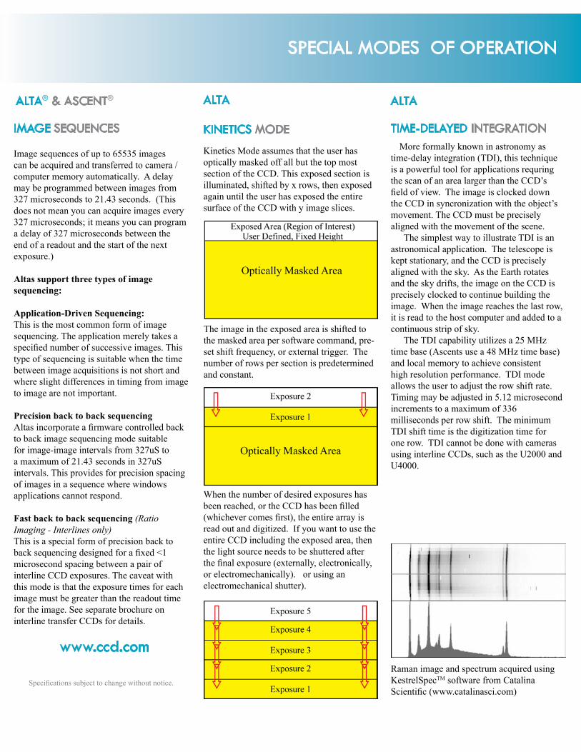
Image sequences of up to 65535 images can be acquired and transferred to camera / computer memory automatically. A delay may be programmed between images from 327 microseconds to 21.43 seconds. (This does not mean you can acquire images every 327 microseconds; it means you can program a delay of 327 microseconds between the end of a readout and the start of the next exposure.)
Altas support three types of image sequencing:
Application-Driven Sequencing:This is the most common form of image sequencing. The application merely takes a specified number of successive images. This type of sequencing is suitable when the time between image acquisitions is not short and where slight differences in timing from image to image are not important.
Precision back to back sequencingAltas incorporate a firmware controlled back to back image sequencing mode suitable for image-image intervals from 327uS to a maximum of 21.43 seconds in 327uS intervals. This provides for precision spacing of images in a sequence where windows applications cannot respond.
Fast back to back sequencing (Ratio Imaging - Interlines only)This is a special form of precision back to back sequencing designed for a fixed <1 microsecond spacing between a pair of interline CCD exposures. The caveat with this mode is that the exposure times for each image must be greater than the readout time for the image. See separate brochure on interline transfer CCDs for details.
IMAGE SEQUENCES
When the number of desired exposures has been reached, or the CCD has been filled (whichever comes first), the entire array is read out and digitized. If you want to use the entire CCD including the exposed area, then the light source needs to be shuttered after the final exposure (externally, electronically, or electromechanically). or using an electromechanical shutter).
The image in the exposed area is shifted to the masked area per software command, pre-set shift frequency, or external trigger. The number of rows per section is predetermined and constant.
Kinetics Mode assumes that the user has optically masked off all but the top most section of the CCD. This exposed section is illuminated, shifted by x rows, then exposed again until the user has exposed the entire surface of the CCD with y image slices.
www.ccd.com
TIME-DELAYED INTEGRATION
ALTAALTA
Raman image and spectrum acquired using KestrelSpecTM software from Catalina Scientific (www.catalinasci.com)
More formally known in astronomy as time-delay integration (TDI), this technique is a powerful tool for applications requring the scan of an area larger than the CCD’s field of view. The image is clocked down the CCD in syncronization with the object’s movement. The CCD must be precisely aligned with the movement of the scene.
The simplest way to illustrate TDI is an astronomical application. The telescope is kept stationary, and the CCD is precisely aligned with the sky. As the Earth rotates and the sky drifts, the image on the CCD is precisely clocked to continue building the image. When the image reaches the last row, it is read to the host computer and added to a continuous strip of sky.
The TDI capability utilizes a 25 MHz time base (Ascents use a 48 MHz time base) and local memory to achieve consistent high resolution performance. TDI mode allows the user to adjust the row shift rate. Timing may be adjusted in 5.12 microsecond increments to a maximum of 336 milliseconds per row shift. The minimum TDI shift time is the digitization time for one row. TDI cannot be done with cameras using interline CCDs, such as the U2000 and U4000.
ALTA® & ASCENT®
ALTA® SERIES CAMERAS: FEATURES
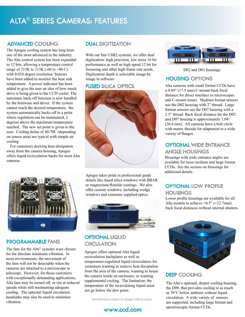
Apogee takes pride in professional grade details like fused silica windows with BBAR or magnesium-flouride coatings. We also offer custom windows, including wedge windows and customer supplied optics.
With our fast USB2 systems, we offer dual digitization: high precision, low noise 16 bit performance as well as high speed 12 bit for focussing and other high frame rate needs. Digitization depth is selectable image by image in software
FUSED SILICA OPTICS
DUAL DIGITIZATION
www.ccd.com
Specifications subject to change without notice.
The Apogee cooling system has long been one of the most advanced in the industry. The Alta control system has been expanded to 12 bits, allowing a temperature control range of 213K to 313K (-60 to +40 C) with 0.024 degree resolution. Sensors have been added to monitor the heat sink temperature. A power indicator has been added to give the user an idea of how much drive is being given to the CCD cooler. The automatic back-off function is now handled by the firmware and driver. If the system cannot reach the desired temperature, the system automatically backs off to a point where regulation can be maintained, 2 degrees above the maximum temperature reached. The new set point is given to the user. Cooling deltas of 40-70C (depending on sensor area) are typical with simple air cooling.
For customers desiring heat dissipation away from the camera housing, Apogee offers liquid recirculation backs for most Alta cameras.
The fans for the Alta® systems were chosen for the absolute minimum vibration. In most environments, the movement of the fans will not be detectable when the cameras are attached to a microscope or telescope. However, for those customers with exceptionally demanding applications, Alta fans may be turned off, or run at reduced speeds while still maintaining adequate cooling. The optional liquid circulation headsinks may also be used to minimize vibration.
PROGRAMMABLE FANS
ADVANCED COOLING
OPTIONAL LIQUID CIRCULATIONApogee offers optional Alta liquid recirculation backplates as well as temperature-regulated liquid recirculators for customers wanting to remove heat dissipation from the area of the camera; wanting to house the camera inside an enclosure; or wanting supplemental cooling. The limitation: the temperature of the recirculating liquid must not go below the dew point.
Alta cameras with small format CCDs have a 0.69” (17.5 mm) C-mount back focal distance for direct interface to microscopes and C-mount lenses. Medium format sensors use the D02 housing with 2” thread. Large format sensors use the D07 housing with a 2.5” thread. Back focal distance for the D02 and D07 housing is approximately 1.04” (26.4 mm). All cameras have a bolt circle with metric threads for adaptation to a wide variety of flanges.
Lower profile housings are available for all Alta models to achieve <0.5” (<12.7mm) back focal distances without internal shutters.
OPTIONAL LOW PROFILE HOUSINGS
HOUSING OPTIONS
Housings with wide entrance angles are available for most medium and large format CCDs. See the section on Housings for additional details.
OPTIONAL WIDE ENTRANCE ANGLE HOUSINGS
D02 and D01 housings
DEEP COOLINGThe Alta’s optional, deeper cooling housing, the D09, that provides cooling to as much as 70°C below ambient without liquid circulation. A wide variety of sensors are supported, including large format and spectroscopic format CCDs.

ALTA® SERIES CAMERAS: FEATURES
The USB2 specification limits cable length to 5 meters, with up to 5 hubs, for a total of 30m. However, there are USB1 and USB2 extenders available for operation up to 10 km. The USB1 extenders slow the transfer to a maximum of 500 kpixels per seoond. USB2 extenders are available using Cat5 cable or fiber optic cable.
RESIDUAL BULK IMAGESSometimes CCD images show very faint ghost images from previous bright images. These residual bulk images (“RBIs”) are caused by trapped electrons, predominantly created at deeper depths by longer wavelengths. RBIs are created in proportion to incoming flux, and therefore are more obvious in those pixels that were very bright in previous images. RBIs are not created by blooming or excess charge in the pixels. RBIs cannot be “fixed” by adjustments to clocks or voltages. However, the “ghost image” effect can be minimized by uniformly filling these deep traps prior to acquiring an image. Some Alta systems, such as the U16M and U9000, include a programmable near-IR pre-flash system.
SINGLE 12V POWER SUPPLYAlta camera systems include a 12V international power supply (100V-240V input), but can be operated from a clean 12V source.
CABLE LENGTH
www.ccd.com
GENERAL I/O PORT FOR ALTA & ASCENT
Our general purpose I/O port can tell you when the shutter is open, or can be used for a wide variety of external trigger inputs, including line-by-line control of TDI shifts.
SHUTTERS
Alta® cameras use three shutter types, depending on the aperture. Apogee shutters use lower voltage coils then those listed as standard by the shutter manufacturers, roughly 1/2 of the standard voltage requirement. The lower voltages extend the lifetimes of the shutters.D01 housing, small format sensors: Vincent Uniblitz 25mm Shutter D02 housing, medium format sensors:Melles Griot 43mm Shutter D07 and D09 housings, large format sensors:Melles Griot 63.5mm Shutter
Full frame CCDs typically require an electromechanical shutter unless the light source is gated in some other way. Otherwise light falling on the sensor during the readout process corrupts the image. Interline CCDs shift the charge from the photodiode section of each pixel to the masked storage diode. For low light applications, the mask is sufficiently opaque to prevent smearing. However, in high light applications, interline CCDs require electromechanical shutters to prevent smearing during readout.
Apogee Imaging Systems uses the finest shutters available for our cameras from Vincent and Melles Griot. These shutters have been carefully integrated into our camera heads with minimum impact on back focal distance and camera size. These shutters have a huge advantage over simple rotating blade shutters in terms of light blockage and minimum exposure time.
Specifications subject to change without notice.
M51 courtesy Greg Morgan, U16M camera. The full image is at the image gallery at www.ccd.com.

www.ccd.com
CCD SELECTION
Specifications subject to change without notice.
CCDs come in many shapes and sizes, as well as several different architectures.
Some architectures were developed specifically to address the needs of extremely low light applications like astronomy (back-illuminated CCDs). Other technologies can be adapted to low light applications with excellent results, but a bit more patience and diligence may be necessary (interline transfer CCDs). Here are some ideas to keep in mind:
Normally larger pixels have higher full well capacities than smaller ones. Higher full well capacities increase the potential maximum signal. If readout noise is kept low, higher signal means a higher signal-to-noise ratio (SNR), which is what allows us to see faint detail without flat-lining the bright spots. High SNR pulls those faint, wispy arms out of a spiral galaxy without making the center into a burned white blob. High SNR can also detect very small changes on top of a deep background, i.e. the stuff that makes discoveries. Get the largest pixel that matches your optics. Need help making the match? Give us a call.
Higher sensitivity = higher quantum efficiency = shorter exposures to get the same results. Shorter exposures = more time for other exposures. The peak value of a quantum effiiciency curve does not tell the full story of a CCD’s sensitivity. The area under the curve gives the true comparison of a CCD’s relative sensitivity. Twice the area under the curve = half the time making the exposure. Or, use the same exposure time, but get twice the signal. Apogee supports front-illuminated, back-illuminated, and interline transfer devices. Back-illuminated CCDs have the highest overall sensitivity. However, they are subject to etaloning (see below) in the near-infrared, especially at longer wavelengths. Front-illuminated CCDs are much less expensive than back-illuminated CCDs and are not subject to etaloning. Interline transfer CCDs can take extremely short exposures, but have the lower sensivity and dynamic range than full frame CCDs.
Color CCDs are convenient for one-shot color, but they compromise in several ways. First, the typical red-green-blue (RGB) Bayer pattern over the pixels of the CCD (see below) cannot be changed--you cannot do monochromatic imaging one day, RGB the next, and cyan-magenta-yellow (CMY) on the third. Second, color CCDs cannot deliver the full resolution of the imager. They can, however, deliver all three color channels at exactly the same instant in time.
Thermally generated signal, or dark current, is not noise. The shot noise component of the dark current is one element of noise, which is the square root of the dark current. You can correct for the dark current itself if you can measure it, which requires the camera’s cooling to be programmable and stable. The deeper the cooling, the less correction you’re going to have to do.
Interline transfer CCDs have, at most, a full well capacity of about 50K electrons. If the electronics limits the read noise to 8-10 electrons, this is a dynamic range of 50K/10 = 5000:1, or about 12.3 bits. Most argue for oversampling by an extra bit, or some argue even two. However, a 16-bit analog-to-digital (AtoD) converter does not upgrade a 12 bit imager into a 16 bit imager. A Kodak KAF-0261E CCD in an Alta U260 camera, using the high dynamic range output amplifier, can be operated at 16 electrons noise RMS with a full well of 500K electrons, or a dynamic range of more than 30K:1, about 15 bits (90 dB).
DYNAMIC RANGE
PIXEL SIZE
QUANTUM EFFICIENCY
DARK CURRENT
COLOR CCDS
Interline transfer CCDs, up to the scale of 35mm film, have inherent anti-blooming, but less dynamic range and lower quantum efficiency than Kodak’s other front-illuminated offerings. Interlines also have high dark current in the storage diodes, as well as some leakage through the storage diode masks. Mass markets for interline CCDs mean much lower prices per pixel, and a great entry point into professional level imaging.
Because interline CCDs shutter the exposure by shifting the charge from the photodiode section of the pixel to the storage diode of the pixel, exposure times can be as short as a few microseconds. Time between exposures is determined by the time required to read out the entire CCD, which varies from camera to camera.
Interline transfer CCDs cannot do time-delayed integration (also known as “drift scan” mode) because charge is not transferred from photodiode to photodiode, but rather into the masked storage diode.
INTERLINE TRANSFER CCDs
Between 200-400 nm, the highest quantum efficiency is found in back-illuminated UV enhanced CCDs such as from e2v and Hama-matsu. Most Kodak CCDs have zero QE at 300 nm, increasing linearly to >40% at 400 nm. Back-illuminated CCDs have the highest QE in the near infrared (NIR), but they are also subject to etaloning (also known as “fringing”). Simply put, the long wavelengths bounce around inside the CCD itself. Some companies have developed proprietary versions of CCDs that minimize, though not eliminate, the effect.
UV & NIR WAVELENGTHS: RECOMMENDATIONS
Typical RGB Bayer filter pattern designed to mimic the responsivity of the human eye.
Quantum efficiency of the Kodak KAI-16000 CCD: black line is monomchrome version; RGB lines are the color version.

www.ccd.com
CCD SELECTION
Specifications subject to change without notice.
CCD GRADES
Each manufacturer’s specification sheet for an imager defines the cosmetic grades for that specific imager. Different manufacturers use different procedures; a grade 1 of Imager A may allow column defects, but a grade 2 (lower grade) of Imager B may not. Kodak usually grades their CCDs at about 25°C, and most of their defects disappear in cooled cameras when the images are flat-fielded. In most cases, you cannot see the difference between the grades. Other companies, such as e2v, grade their CCDs at low temperatures, so their defects are less likely to disappear when the CCD is cooled.
Defects on CCDs do not grow or move over time. They are mappable. Lower grade CCDs do not wear out faster. Most lower grade Kodak CCDs no longer allow column defects. These lower priced CCDs are excellent bargains.
Please check the manufacturers’ data sheets for each CCD carefully before purchasing a system. Some large format CCDs allow several column defects in the “standard grade” CCD, If you have trouble finding or understanding their cosmetic gradings, please ask us for help.
Anti-blooming (AB) bleeds off excess charge from individual pixels so that it does not spill over into neighboring pixels, causing a white stripe down the column. For applications like astrophotography, AB preserves the aesthetics of the image. For photometric applications, AB can be used if exposure times are carefully controlled to avoid excess charge. In the past, AB drastically lowered full well capacity and quantum efficiency. Newer Kodak CCDs have anti-blooming with higher quantum efficiency and full well capacities.
ANTI-BLOOMING KODAK BLUE PLUS CCDsCCDs create charge due to the photoelectric effect. In order to create an image rather than random electricity, the charge must be held where it was created. “Traditional” CCDs use from one to four polysilicon gates to carry a voltage that traps the charge until transferred. Polysilicon has limited transmissivity. Indium tin oxide (ITO) gates have higher transmissivity, but lower charge transfer efficiency. Kodak’s combination of one polysilicon gate and one ITO gate is marketed as Blue Plus (because of the increase in blue sensitivity). The overall sensitivity of Blue Plus CCDs is much higher than multi-phase front-illuminated CCDs using only polysilicon gates. However, when researching point sources of light, it is good to keep in mind that there is a marked increase in quantum effiiency on the ITO side of each pixel. (See MICROLENSES below).
MICROLENSED CCDsMany CCDs now use microlenses over each pixel. In the case of interline transfer CCDs, the microlenses focus the light onto the photodiode. In the case of Kodak’s Blue Plus CCDs (see above), the microlenses focus the light onto the ITO gate side of the pixel. Microlenses greatly improve overall quantum efficiency, but introduce some angular dependency. Fill factor is normally less than 100%. See data sheets for individual CCDs for details.
TYPICAL PERFORMANCECCD manufacturers specify their sensors in terms of typical performance and worst performance. For example, a specification sheet may say “15 electrons noise typical, maximum 20 electrons noise.” Such a CCD with 18 electrons noise may be noisier than “normal”, but it does meet the manufacturer’s specification and cannot be returned to the manufacturer. Asking the CCD manufacturer to guarantee a “typical” value can increase the price of the CCD by a factor of 3-4X. Apogee’s published prices are based on unsorted CCDs that meet the manufacturer’s specifications for the grade ordered. Please note that CCD manufacturer’s test conditions may not be representative of performance in an Apogee camera. e2v, for example, normally tests readout noise at 20 kHz, much slower than the 700 kHz readout of an Alta camera in 16 bit mode.
E2V CCDs: AIMO & NIMOE2V’s AIMO (Advanced I Metal Oxide, aka MPP) CCDs have hundreds of times less dark current than non-IMO (NIMO) CCDs. Some variations of their CCDs, such as the enhanced UV response CCD42-40 found in the U42-UV camera, are only available as NIMO devices.
Close-up of legacy Kodak KAF-1602 CCD
Alta U16M camera with fiber optically bonded CCD
FIBER OPTIC BONDINGApogee now offers fiber optically bonded versions of the Alta cameras. Pictured to the left is a U16M camera with a fiber attached to the CCD. Applications for bonding including radiology, transmission electron microscopy, x-ray crystallography, and gated image intensifiers. Please contact us with your requirements.

For complete CCD specifications, including cosmetic grading, see data sheet from manufacturer.
Imaging Area of CCD
U432048 x 2048
24 micron pixels
U16M & U164096 x 4096
9 micron pixels
U9000 & U9000X3056 x 3056
12 micron pixels
CameraModel Kodak CCD* Array Size
Total Pixels
Pixel Size(µ)
Array size (mm)
Imaging Area
(mm2)Diagonal
(mm)
VideoImager
SizeMono=MColor=CX Y
U39000 KAF-39000 7216 5412 39052992 6.8 49.1 36.8 1805 61.3 3.83” M,CU16 KAF-16801E 4096 4096 16777216 9 36.9 36.9 1359.0 52.1 3.3” M
U16M KAF-16803 4096 4096 16777216 9 36.9 36.9 1359.0 52.1 3.3” MU9000 KAF-09000 3058 3058 9351364 12 36.7 36.7 1346.6 51.9 3.2” MU8300 KAF-8300E or CE 3448 2574 8875152 5.4 18.6 13.9 259 23.2 1.4” M,C
U9 KAF-6303E 3072 2048 6291456 9 27.6 18.4 509.6 33.2 2.1” MU43 KAF-4320E 2048 2048 4194304 24 49.1 49.1 2415 69.5 4.3” M
U3041F Fairchild CCD3041 2048 2048 4194304 15 30.7 30.7 943.7 43.3 2.7” MU10 e2v TH7899* 2048 2048 4194304 14 28.7 28.7 822.1 40.6 2.5” M
U32 KAF-3200 2184 1472 3214848 6.8 14.9 10.0 148.7 17.9 1.1” MU2 KAF-1603ME 1536 1024 1572864 9 13.8 9.2 127.4 16.6 1.0” MU6 KAF-1001E 1024 1024 1048576 24 24.6 24.6 604.0 34.8 2.2” MU1 KAF-0402ME 768 512 393216 9 6.9 4.6 31.9 8.3 0.5” M
U30-OE e2v CCD30-11 1024 256 262144 26 26.6 6.7 177.2 27.4 1.7” MU260 KAF-0261E 512 512 262144 20 10.2 10.2 104.9 14.5 0.9” M
Alta® Series cameras with a USB2 interface use a U prefix, for example, U42. This page lists the U Series systems available with front-illuminated CCDs. For listings of back-illuminated CCDs, interline transfer CCDs, and spectroscopic format CCDs, see the following pages.
*The U10 uses an e2v (formerly Atmel, formerly Thomson) TH7899 CCD.
CCD ARRAY SIZES
U10
U9
U6
U32 U1
U2
U260
FRONT ILLUMINATED CCDs
U8300
ALTA® Full-Frame Front-Illuminated CCDs:Supported CCDs
U30-OE
Horsehead Nebula (NGC 2023) by Ken Crawford, U9000 camera (full
image in the gallery at www.ccd.com)
U3041F2048 x 2048
15 micron pixels
U390007216 x 5412
6.8 micron poixels

ALTA® Full-Frame Front-Illuminated CCDs:Specifications
D07F Housing for U16, U16M,
U9000, and U16000
CameraModel
LinearFull Well(typical)
Dyn.Range (dB)
QE@400nm
PeakQE
Anti-Bloom-
ing
ReadNoise(typ.)1
Cooling2
(∆C)Dark Current2
(Typical)Cooling3
(∆C)
Deep CoolingDark Current3
(Typical)U39000 60K 71 18% 32% NA 16 e- 50 0.03 e/p/s NA NA
U16 100K e- 81 31% 69% NA 9 e- 40 0.3 e/p/s 60 0.04 e/p/sU16M 85K e- 79 41% 60% >100X 9 e- 40 0.2 e/p/s 60 0.03 e/p/sU9000 110K e- 82 37% 64% >100X 9 e-4 40 0.3 e/p/s 60 0.04 e/p/sU8300 25.5K e- 70 38%5 56%5 1000X 9 e- 50 0.02 e/p/s 70 0.002 e/p/s
U9 100K e- 79 30% 67% NA 11 e- 45 0.3 e/p/s 65 0.04 e/p/sU43 500K e- 88 39% 72% NA 12 e- 50 2 e/p/s NA NA
U3041F 100K e- 82 3% 43% NA 10 e- 40 1 e/p/s NA NAU10 150K e- 78 0.5% 38% NA 19 e- 40 0.8 e/p/s NA NAU32 55K e- 77 53% 86% NA 8 e- 50 0.08 e/p/s NA NAU2 100K e- 78 44% 82% NA 12 e- 50 0.2 e/p/s NA NAU6 HG:200K e-6 87 39% 72% NA 9 e-6 45 0.4 e/p/s 65 .05 e/p/sU1 100K e- 79 53% 85% NA 11 e- 50 0.1 e/p/s NA NA
U30-OE 300K e- 84 24% 59% NA 20 e- 50 0.2 e/p/s 70 0.02 e/p/s
U260 HG: 200K e-6 866 29% 65% NA 10 e-6 50 0.2 e/p/s NA NA
Notes:1. Read noise in 16 bit mode. Noise in 12 bit mode is typically 2 counts.2. Cooling with standard, low profile, or wide angle housing.3. Cooling with high cooling housing (D09).4. Read noise for U9000X in 16 bit mode is typically 12 e-.5. Quantum efficiency (QE) for monochrome version of CCD. See QE curves regarding color version of CCD.6. The CCDs in the U6 and U260 have two output amplifiers: high gain (for low noise) and low gain (for high dynamic range). One amplifier must be chosen at the time the camera is manufactured. Full well capacity for the U6 and U260 using the high gain amplifier is about 200K e-; in low gain, about 500K e-. Read noise for low gain is typically 22 e- for the U6 or 16 e- for the U260. Dynamic range for the U260 in LG mode is about 90 dB.
TYPICAL PERFORMANCE
Most of the CCDs are offered in several different housings: standard, low profile, wide angle, and high cooling. For details, see the following section regarding housings.
Image courtesy Dr. David Rapaport, UCSD
©2011 Apogee Imaging Systems Inc. Alta and Ascent are registered trademarks of Apogee Imaging Systems Inc. Specifications subject to change without notice.

For complete CCD specifications, including cosmetic grading, see data sheet from manufacturer.
Imaging Area of CCD
U230U3041
2048 x 204815 micron pixels
U422048 x 2048
13.5 micron pixels
U160004872 x 3248
7.4 micron pixels
CameraModel CCD Array Size
Total Pixels
Pixel Size(µ)
Array size (mm)
Imaging Area
(mm2)Diagonal
(mm)
VideoImager
SizeMono=MColor=CX Y
Back-illuminated CCDsU42 e2v CCD42-40 2048 2048 4194304 13.5 27.6 27.6 764 39.1 2.4 M
U42-UV e2v CCD42-40 2048 2048 4194304 13.5 27.6 27.6 764 39.1 2.4 MU230 e2v CCD230-42 2048 2048 4194304 15 30.7 30.7 944 43.4 2.7 MU3041 Fairchild 3041 2048 2048 4194304 15 30.7 30.7 944 43.4 2.7 MU47 e2v CCD47-10 1024 1024 1048576 13 13.3 13.3 177 18.8 1.2 MU77 e2v CCD77-00 512 512 262144 24 12.3 12.3 151 17.4 1.1 MU30 e2v CCD30-11 1024 256 262144 26 26.6 6.6 177 27.4 1.7 M
U1109 Hama. S10140-1109 2048 506 1036288 12 24.6 6.1 149 25.3 1.6 MU1107 Hama. S10140-1107 2048 122 249856 12 24.6 1.5 36 24.6 1.5 MU1009 Hama. S10140-1009 1024 506 518144 12 12.3 6.1 75 13.7 0.9 M
Interline Transfer CCDsU16000 Kodak KAI-16000 4096 4096 16777216 7.4 36 24 866 43.3 3.3 M, CU4000 Kodak KAI-04022 2048 2048 4194304 7.4 15.2 15.2 230 21.4 1.3 M, CU2000 Kodak KAI-2020 1600 1200 1920000 7.4 11.8 8.9 105 14.8 0.9 M, C
Alta® Series cameras with a USB2 interface use a U prefix, for example, U42. See previous pages for full frame front illuminated CCDs.
CCD ARRAY SIZES
U1109
U4000
U47
BACK ILLUMINATED CCDsU2000
ALTA® Back-Illuminated & Interline Transfer CCDs:Supported CCDs
U77
INTERLINE TRANSFER CCDs(available with monochrome or color CCDs)
U1107
U1009
U30
D09L Housing with optional
LR001 Liquid Recirculation Unit
D01 Housing

CameraModel
LinearFull Well(typical)
Dyn.Range (dB)
QE@400nm
PeakQE
Anti-Bloom-
ing
ReadNoise(typ.)1
Cool-ing2
(∆C)Dark Current2
(Typical)Cooling3
(∆C)
Deep CoolingDark Current3
(eps)Back-illuminated CCDs
U42 100K e- 80 55% 96% NA 10 e- 40 0.9 e/p/s 60 0.1 e/p/sU42-UV 150K e- 84 57% 65% NA 10 e- 40 400 e/p/s 60 35 e/p/s
U230 150K e- 85 55% 96% NA 12 e- 40 0.4 e/p/s 60 0.04 e/p/sU3041 100K e- 82 74% 96% NA 10 e- 40 2 e/p/s 60 0.3 e/p/sU47 100K e- 81 55% 96% NA 9 e- 50 0.4 e/p/s 70 0.04 e/p/sU77 350K e- 89 55% 96% NA 12 e- 50 0.6 e/p/s 70 0.06 e/p/sU30 500K e- 88 55% 96% NA 21 e- 50 0.5 e/p/s 70 0.05 e/p/s
U1109 75K e- 71 58% 89% NA 20 e- 50 2.2 e/p/s 70 0.2 e/p/sU1107 75K e- 71 58% 89% NA 20 e- 50 2.2 e/p/s 70 0.2 e/p/sU1009 75K e- 71 58% 89% NA 20 e- 50 2.2 e/p/s 70 0.2 e/p/s
Interline Transfer CCDsU16000 30K e- 73 39% 48% 300X 7 e- 40 0.2 e/p/s 60 0.02 e/p/sU4000 40K e- 75 44% 55% 300X 7 e- 54 0.3 e/p/s 75 0.03 e/p/sU2000 40K e- 75 47% 56% 300X 7 e- 54 0.4 e/p/s 75 0.04 e/p/s
Notes:1. Read noise in 16 bit mode. Noise in 12 bit mode is typically 2 counts.2. Cooling with standard, low profile, or wide angle housing (Fan / Liquid Circulation).3. Cooling with high cooling housing (Fan / Liquid Circulation).4. Quantum efficiency (QE) for monochrome version of CCD. See QE curves regarding color version of CCD.
TYPICAL PERFORMANCE
Most of the CCDs are offered in several different housings: standard, low profile, wide angle, and high cooling. For details, see the following section regarding housings.
ALTA® Back-Illuminated & Interline Transfer CCDs:Specifications
Above: Echelle spectrograph image from deuterium-tungsten source (UV at top). Below: linearized spectrum created from the image, generated by linking the multiple orders together. Echelle spectrographs offer much higher sampling resolution by taking advantage of the area of imaging CCDs.
Interline transfer CCDs are the most popular choice for imaging of microtitre plates.www.ccd.com

ALTA® Full-Frame Front-Illuminated CCDs:Quantum Efficiency
Abs
olut
e Q
uant
um E
ffici
ency
(%)
Wavelength (nm)
U16M U9000 & U9000X U16 U4320
Abs
olut
e Q
uant
um E
ffici
ency
(%)
Wavelength (nm)
U260 U6 U10 (similar to U3041F) U32
0
10
20
30
40
50
60
70
80
360
380
400
420
440
460
480
500
520
540
560
580
600
620
640
660
680
700
720
740
760
780
800
820
840
860
880
900
920
940
960
980
1000
1020
1040
1060
1080
1100
0
10
20
30
40
50
60
70
80
90
100
300
340
380
420
460
500
540
580
620
660
700
740
780
820
860
900
940
980

05
1015202530354045
360
420
480
540
600
660
720
780
840
900
960
1020
1080ALTA® Full-Frame Front-Illuminated CCDs:
Quantum EfficiencyA
bsol
ute
Qua
ntum
Effi
cien
cy (%
)A
bsol
ute
Qua
ntum
Effi
cien
cy (%
)
Wavelength (nm)
U1 & U2 U9 U8300
Wavelength (nm)
U8300C U39000
0
10
20
30
40
50
60
70
80
90
2002302602903203503804104404705005305605906206506807107407708008308608909209509801010104010701100
e2v OE
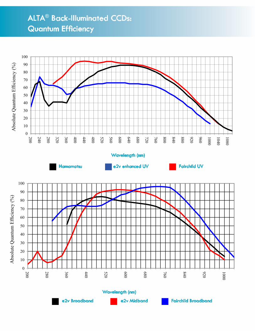
ALTA® Back-Illuminated CCDs:Quantum Efficiency
Abs
olut
e Q
uant
um E
ffici
ency
(%)
Wavelength (nm)
Hamamatsu e2v enhanced UV Fairchild UV
Abs
olut
e Q
uant
um E
ffici
ency
(%)
Wavelength (nm)
e2v Broadband e2v Midband
0
10
20
30
40
50
60
70
80
90
100
200
280
360
440
520
600
680
760
840
920
1000
Fairchild Broadband
0
10
20
30
40
50
60
70
80
90
100
200
240
280
320
360
400
440
480
520
560
600
640
680
720
760
800
840
880
920
960
1000
1040
1080

Abs
olut
e Q
uant
um E
ffici
ency
(%)
Abs
olut
e Q
uant
um E
ffici
ency
(%)
Wavelength (nm)
U16000A285 U4000 U2000 A205
Wavelength (nm)
U16000, U4000, & U2000 Color
ALTA® / Ascent® Interline Transfer CCDs:Quantum Efficiency
05
101520253035404550
400
440
480
520
560
600
640
680
720
760
800
840
880
920
960
1000
Monochrome Version of the CCD
0
10
20
30
40
50
60
70
350
380
410
440
470
500
530
560
590
620
650
680
710
740
770
800
830
860
890
920
950
980
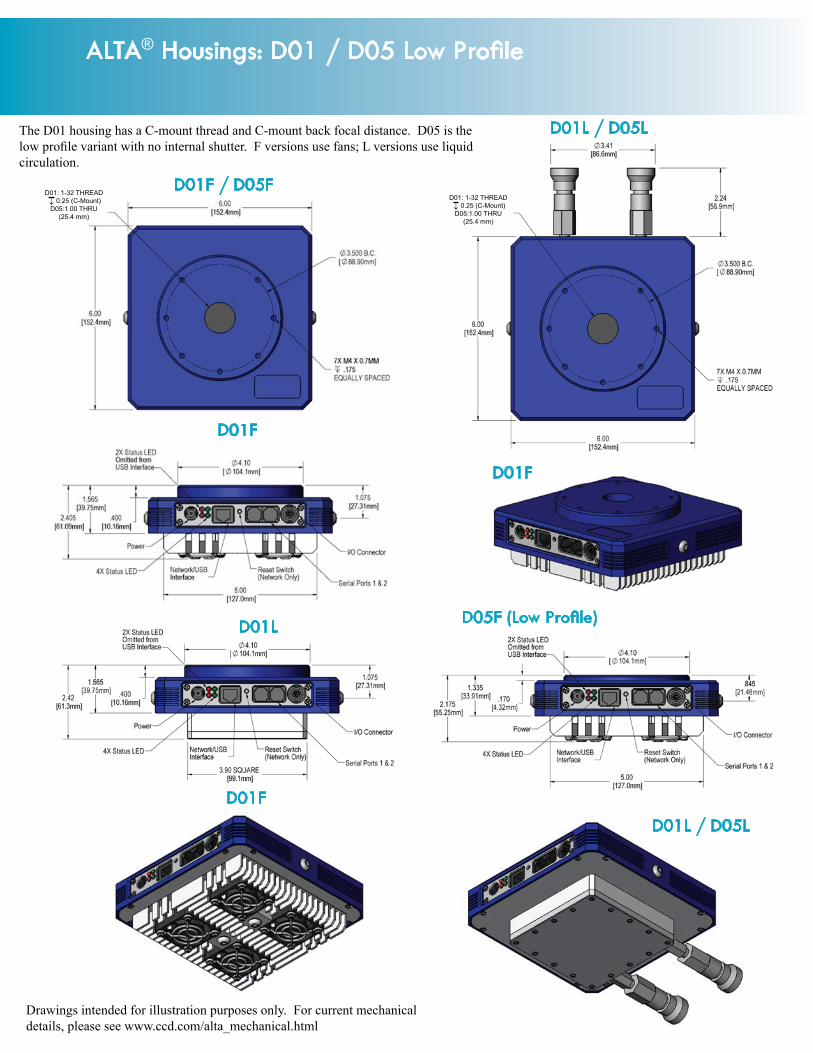
ALTA® Housings: D01 / D05 Low Profile
D01F / D05F
D01L / D05L
D01F
D01L / D05L
D05F (Low Profile)
D01F
D01F
Drawings intended for illustration purposes only. For current mechanical details, please see www.ccd.com/alta_mechanical.html
The D01 housing has a C-mount thread and C-mount back focal distance. D05 is the low profile variant with no internal shutter. F versions use fans; L versions use liquid circulation.
D01L
D01: 1-32 THREAD 0.25 (C-Mount)D05:1.00 THRU
(25.4 mm)
↓D01: 1-32 THREAD 0.25 (C-Mount)D05:1.00 THRU
(25.4 mm)
↓

ALTA® Housings: D02 / D06 Low Profile
The D02 housing has a 2” thread. D06 is the low profile variant with no internal shutter.
D02F / D06F
D02F
D02L
D02F
D02F
D06F (Low Profile)
D02L
D02L / D06L
D02: 2-24 THREAD 0.25
D06:1.77 THRU (44.96 mm)
↓
D02: 2-24 THREAD 0.25
D06:1.77 THRU (44.96 mm)
↓

For additional dimensional details, see complete mechanical drawings at www.ccd.com/alta_mechanical.html
ALTA® Housings: D07 / D11 Low Profile
D07F D11F (Low Profile)

ALTA® Housings: D10
D10FNo liquid circulation version of D10 is available.
NGC 6188, courtesy Don Goldman. U16M camera.
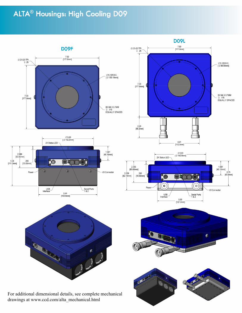
ALTA® Housings: High Cooling D09
D09FD09L
For additional dimensional details, see complete mechanical drawings at www.ccd.com/alta_mechanical.html
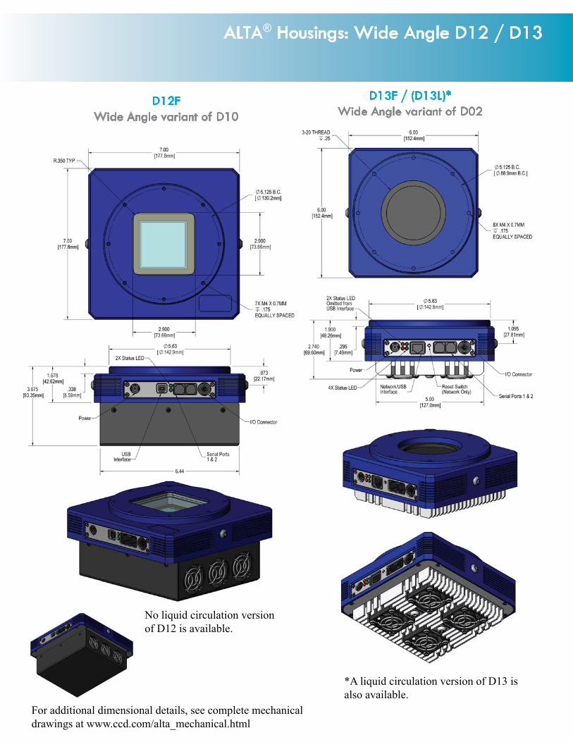
For additional dimensional details, see complete mechanical drawings at www.ccd.com/alta_mechanical.html
ALTA® Housings: Wide Angle D12 / D13
D13F / (D13L)*Wide Angle variant of D02
D12FWide Angle variant of D10
*A liquid circulation version of D13 is also available.
No liquid circulation version of D12 is available.

InterfaceU = USB 2.0
D10F-VS90D-U04320-MNSAHousingD01D02D05D06D07D09D10D11D12D13
Heat TransferF = FanL = Liquid
ShutterVS25 = Vincent 25mmMG45 = Melles Griot 45mmMG63 = Melles Griot 63mmVS90 = Vincent 90mmNOSH = No shutter CCD
00402 = Kodak KAF-0402ME (U1)A0261 = Kodak KAF-0261E, High Gain (U260)B0261 = Kodak KAF-0261E, High Dynamic Range01603 = Kodak KAF-1603 (U2)03011 = e2v CCD30-11 open electrode (U30-OE)03200 = Kodak KAF-3200ME (U32)A1001 = Kodak KAF-1001E, High Gain (U6)B1001 = Kodak KAF-1001E, High Dynamic Range06303 = Kodak KAF-6303E (U9)07899 = e2v TH7899 (U10)08300 = Kodak KAF-8300 (U8300)04320 = Kodak KAF-4320 (U43)09000 = Kodak KAF-09000 (U9000, U9000X)16803 = Kodak KAF-16803 (U16M)16801 = Kodak KAF-16801E (U16)39000 = Kodak KAF-39000 (U39000)03041 = Fairchild CCD3041 (U3041F)
CCD TypeMN = Monochrome, non-microlensedMM = Monochrome, microlensedCM = Color, microlensedOE = Open electrode (e2v)
CCD Grade(as defined by manufacturer)S = Standard0 = Grade 0 (e2v only)1 = Grade 12 = Grade 2H = Grade H (TH7899 only)E = Grade E (TH7899 only)X = Engineering Grade
16-bit digitizationA = 1 MHzX = 1.8 MHz
Inner Chamber WindowS = SingleD = DoubleW = Wedge
ALTA® Full-Frame Front-Illuminated CCDs:Part Numbers
Image courtesy Scientific Instrument Company.
©2011 Apogee Imaging Systems Inc. Alta and Ascent are registered trademarks of Apogee Imaging Systems Inc.
Specifications subject to change without notice.

ALTA® Full-Frame Front-Illuminated CCDs:Available Configurations
Flange adapters allow you to attach anything from an SLR camera lens to a large instrument pack to your Apogee camera. We have sizes to fit all Alta and Ascent cameras. These units are machined precisely for accurate concentricity.
The new Icron USB 2.0 Ranger® extenders support USB cameras at distances from 50 meters (Cat 5 cable) to 10 km (fiber cable).
Apogee offers an optional filter wheel for nine 2” round filters or seven 2” square filters. The filter wheel can be controlled di-rectly from one of the Alta’s COM ports. The filter wheel is pictured here on the optional D09 housing.
ALTA FILTER WHEEL FACE PLATE ADAPTERS
USB2 EXTENDERS
Camera Std Housing* High Cooling Low Profile Wide Angle Interface Grades Digit.U39000 D10F-VS90S NA D12F-NOSHS NA U 1 AU16M D07F-MG63D D09*-MG63D D11F-NOSHD NA U S AU16 D07F-MG63D D09*-MG63D D11F-NOSHD NA U 1, 2 AU9000 D07F-MG63D D09*-MG63D D11F-NOSHD NA U S A, XU8300 D02*-MG43D D09*-MG63D D06*-NOSHD D13*-MG63D U, E S AU9 D02*-MG43D D09*-MG63D D06*-NOSHD D13*-MG63D U, E 1, 2 AU43 D10*-VS90S NA NA D12*-NOSHS U 1, 2 AU3041F D02*-MG43D NA D06*-NOSHD D13*-MG63D U, E 1 AU10 D02*-MG43D NA D06*-NOSHD D13*-MG63D U, E H, E A
U32 D01*-VS25D NA D05*-NOSHD NA U, E 1, 2 AU2 D01*-VS25D NA D05*-NOSHD NA U, E 2 AU6 D02*-MG43D D09*-MG63D D06*-NOSHD D13*-MG63D U, E 1, 2 AU1 D01*-VS25D NA D05*-NOSHD NA U, E 1, 2 AU260 D01*-VS25D NA D05*-NOSHD NA U, E 1 AU30-OE D02*-MG43D D09*-MG63D D06*-NOSHD D13*-MG63D U, E 0, 1 A
Items with * are available with fans or with liquid circulation. Liquid circulation is not intended to add cooling, but rather to dissipate heat away from the camera. The fan cooled version is D09F, for example, and the liquid cooled version is D09L.
D01 D02 D05 D06 D07 D09 D10 D11 D12 D13Weight (lb.) 3.1 3.1 3.0 2.8 4.2 7.2 7.5 6.3 7.2 3.6
Weight (kg.) 1.4 1.4 1.4 1.3 1.9 3.3 3.4 2.9 3.3 1.6BFD (inches)* 0.69 1.02 0.46 0.46 1.0 1.4 1.22 0.58 0.70 1.05BFD (mm)* 17.5 25.9 11.7 11.7 25.4 35.6 31.0 14.7 17.8 26.7
*BFD = Back focal distance, optical (compensating for the optical elements within the camera). Distances are approximate; see mechanical drawings at www.ccd.com/alta_mechanical.html for precise information.

Inner Chamber WindowS = Single
D = DoubleW = Wedge
InterfaceU = USB 2.0
D02F-MG43D-U04240-MB1AHousingD01D02D05D06D07D09D10D11D12D13
Heat TransferF = Fan
L = Liquid
ShutterVS25 = Vincent 25mm
MG45 = Melles Griot 45mmMG63 = Melles Griot 63mm
VS90 = Vincent 90mmNOSH = No shutter
CCD23042 = e2v CCD230-42 (U230)03041 = Fairchild 3041 (U3041)04240 = e2v CCD42-40 (U42)04710 = e2v CCD47-10 (U47)07700 = e2v CCD77-00 (U77)03011 = e2v CCD30-11 (U30)01109 = Hamamatsu S10140-1109 (U1109)01108 = Hamamatsu S10140-1108 (U1108)01107 = Hamamatsu S10140-1107 (U1107)01009 = Hamamatsu S10140-1009 (U1009)01008 = Hamamatsu S10140-1008 (U1008)01007 = Hamamatsu S10140-1007 (U1007)09840 = Hamamatsu S9840 (U98)16000 = Kodak KAI-16000 (U16000)04022 = Kodak KAI-4022 (U4000)02020 = Kodak KAI-2020 (U2000)
CCD TypeMM = Monochrome, microlensedCM = Color, microlensedMB = MidbandBB = BroadbandUV = UV enhanced
CCD Grade(as defined by manufacturer)S = Standard0 = Grade 0 (e2v only)1 = Grade 12 = Grade 2X = Engineering Grade
16-bit digitizationA = 1 MHz (Interlines); = 700 kHz (Back-illums)
ALTA® Back-Illuminated & Interline Transfer CCDs:Part Numbers & Available Configurations
Camera Std Housing* High Cooling Low Profile Wide Angle Interface Grades TypesBack-illuminated CCDs
U230 D07F-MG63D D09*-MG63D D11F-NOSHD NA U 0, 1, 2 MBU3041 D07F-MG63D D09*-MG63D D11F-NOSHD NA U 1, 2, 3 BB,UVU42 D02F-MG43D D09*-MG63D D06*-NOSHD D13*-MG63D U, E 0, 1 MB,UVU47 D02*-MG43D D09*-MG63D D06*-NOSHD D13*-MG63D U, E 0, 1 MB,BB,UVU77 D02*-MG43D D09*-MG63D D06*-NOSHD D13*-MG63D U, E 0, 1 MBU30 D02*-MG43D D09*-MG63D D06*-NOSHD D13*-MG63D U, E 0, 1 MB, UVU1109 D02*-MG43D D09*-MG63D D06*-NOSHD D13*-MG63D U, E S UVU1108 D02*-MG43D D09*-MG63D D06*-NOSHD D13*-MG63D U, E S UVU1107 D02*-MG43D D09*-MG63D D06*-NOSHD D13*-MG63D U, E S UVU1009 D02*-MG43D D09*-MG63D D06*-NOSHD D13*-MG63D U, E S UVU1008 D02*-MG43D D09*-MG63D D06*-NOSHD D13*-MG63D U, E S UVU1007 D02*-MG43D D09*-MG63D D06*-NOSHD D13*-MG63D U, E S UVU98 D02*-MG43D D09*-MG63D D06*-NOSHD D13*-MG63D U, E S UV
Interline Transfer CCDsU16000 D07F-MG63D D09*-MG63D D11F-NOSHD NA U 1, 2 MM,CMU4000 D02*-NOSHD D09*-MG63D D06*-NOSHD D13*-MG63D U, E S MM,CMU2000 D01*-NOSHD NA D05*-NOSHD NA U, E S MM,CM
1. Items with * are available with fans or with liquid circulation. Liquid circulation is not intended to add cooling, but rather to dissipate away from the camera. The fan cooled version is D09F, for example, and the liquid cooled version is D09L.2. The U4000 and U2000 are optionally available with internal shutters, D01*-VS25D and D02*-MG43D, respectively.3. The U47 is also available in a C-mount configuration, D01*-VS25D. However, the CCD is a 1.2” format by video standards (19mm diagonal) so is too large for most C-mount lenses.

AFW Filter Wheels
©2011 Apogee Imaging Systems Inc. Alta and Ascent are registered trademarks of Apogee Imaging Systems Inc. Specifications subject to change without notice.
The AI-FW50 series of filter wheels provide filtering solutions for Alta and Ascent cameras with large format CCDs, such as the A16000. The AFW50-9R filter wheel provides 9 positions for 50mm / 2” round filters. The AFW50-7S and AFW50-10S provide 7 and 10 positions for 50mm / 2” square filters, respectively. The filter wheels are controlled via USB 2.0. The filter wheels easily adapt to Alta and Ascent bodies.
Max. filter thickness 7 mm
Weight 3.5 lbs. (1.6 kg) with filtersThickness 1.15” (2.92 cm) with mounting plateCamera mount method Adapter plate attached to Alta, Ascent or AP
cameraMechanical mount 3” 24 threads/inchPower input 12V DC (int’l power supply included)Interface USB 2.0
AFW50-7S Filter wheel with Alta adapter plate
Filter wheel mounted on Alta D09 camera body
AFW-50-9R Carousel9 positions for 50mm
round filtersAFW-50-10S Carousel10 positions for 50mm
square filters
AFW-50-7S Carousel7 positions for 50mm
square filters
(All dimensions in inches)

Aerospace Corporation • Air Force Research Laboratory • Aloe Ridge Observatory (South Africa) • American Red Cross • Anglo-Australian Observatory • Ankara University Observatory (Turkey) • Apache Point Observatory • Appalachian State University • Argonne National Laboratory
• Astronomical Institute of the Czech Republic • Astronomical Observatory Belgrade (Yugoslavia) • Astrophysical Observatory, College of Staten Island • Auckland Observatory (New Zealand) • Bacs-Kiskun Observatory (Hungary) • Baja Astronomical Observatory (Hungary) • Ball
Aerospace • Bang & Olufsen (Denmark) • Baton Rouge Observatory • Baylor University • Bechtel • Beijing Observatory (China) • Big Bear Solar Observatory • Boeing • Bohyunsan Optical Astronomy Observatory (Korea) • Boston University • Brigham Young University • California Institute of Technology • Centre National de la Recherche Scientifique (France) • Centro de Investigaciones en Optica (México) • Chiang Mai University
(Thailand) • Chiba University (Japan) • Chinese University of Hong Kong • Clemson University • Colorado School of Mines • Columbia University • Complejo Astronómico El Leoncito (Argentina) • Copenhagen University (Denmark) • Cork Institute of Technology (Ireland) • Corning • Crimean
Astrophysical Observatory (Ukraine) • Czech Technical University (Czech Republic) • Daimler Benz Aerospace (Germany) • Department of National Defence, Canada • DLR e.V. (Germany) • Dublin Institute for Advanced Studies, Dunsink Observatory (Ireland) • Dworp Observatory (Belgium)
• Eastman Kodak • Ege University (Turkey) • Florida Institute of Technology / SARA • Ford Motor • Fox Chase Cancer Center • Fudan University (China) • Fuji • Fujitsu • Gemini Telescope Project • Gøteburg University (Sweden) • Harvard-Smithsonian Center for Astrophysics • Harvard College Observatory • Heron Cove Observatory • Hida Observatory (Japan) • High Energy Accelerator Research Organization (Japan) • High
Frequency Active Auroral Research Program (HAARP) • Hiroshima University (Japan) • Hitachi • Hong Kong University of Science & Technology • Imation • Indian Institute of Astrophysics • Industrial Technology Research Institute (ITRI) (Taiwan) • Institute for Astronomy, Hawaii • Institute of
Astronomy (Switzerland) • Institute of Astronomy and Astrophysics (Taiwan) • Institute of Atomic and Molecular Sciences (Taiwan) • Institute for Quantum Physics (Switzerland) • Instituto de Astrofisica de Andalucia (Spain) • Instituto de Astrofisica de Canarias (Spain) • Inst. Estudis Espacials
de Catalunya (Spain) • International Science & Technology Centre (Russia) • IVIC-CBB (Venezuela) • J.Paul Getty Museum • Jagellonian University (Poland) • Japan Atomic Energy Agency • Jet Propulsion Laboratory • Johns Hopkins University • Kimberly-Clark • Kim-Hae Observatory (Korea)
• Kitt Peak National Observatory • Konkoly Observatory (Hungary) • Korea Astronomical Observatory • Korea Research Institute of Standards and Science • Kwasan Observatory (Japan) • Kyoto University (Japan) • Lancaster University (UK) • Landessternwarte Heidelberg-Königstuhl
(Germany) • Las Cumbres Observatory • Lawrence Berkeley National Laboratory • Lawrence Livermore National Laboratory • Lick Observatory • Liverpool John Moores University (UK) • Lockheed Martin • London Health Sciences Centre (Canada) • Los Alamos National Laboratory •
Lucent Technologies • Lund Observatory (Sweden) • Mauna Loa Observatory • Max Planck Institute (Germany) • McGill University (Canada) • MIT • MIT Lincoln Laboratory • Mt. Cuba Astronomical Observatory • Mt. Diablo Observatory • Mt. Stromlo Observatory (Australia) • Mt. Wilson
Observatory • Multiple Mirror Telescope • Nagoya University (Japan) • NASA Goddard SFC • NASA Marshall SFC • NASA Langley Research Center • National Astronomical Observatory (Japan) • National Central University (Taiwan) • National Cheng Kung University (Taiwan) • National Health Research (Taiwan) • National Institute for Advanced Interdisciplinary Research (Japan) • National Institute of Advanced Industrial Science
and Technology (Japan) • National Institute for Materials Science (Japan) • National Institute of Standards & Technology • National Oceanographic and Atmospheric Administration • National Solar Observatory • National Sun Yat-Sen University (Taiwan) • National Tsing Hua University (Taiwan)
• National University of Ireland • Naval Post Graduate School • Naval Research Laboratory • Northwestern University • NTT (Japan) • Oak Ridge National Laboratory • Observatoire Côte d’Azur (France) • Observatoire de Geneve (Switzerland) • Observatorio “Carl Sagan” (Mexico) • Occidental College • Okayama Astrophysical Observatory (Japan) • Oxford University (UK) • Osaka University (Japan) • Oulu University (Finland) • Panasonic
• Physical Research Laboratory (India) • Police Scientific Development Branch, Scotland Yard (UK) • Pomona College • Portland State University • Princeton University • Purdue University • Purple Mountain Observatory (China) • Queens University (Canada) • Rice University • Riken (Japan) • Rockefeller University • Royal Military College of Canada • Royal Observatory (Edinburgh, Scotland) • Russian Academy of Sciences • Sandia
National Laboratory • Science and Technology Centre of Ukraine • Shamakhy Astrophysical Observatory (Azerbaijan) • Smithsonian Observatory • South African Astronomical Observatory • Stanford University • State Universities of Arizona, Georgia, Iowa, Louisiana, Michigan, Montana, New York (SUNY), North Carolina, Ohio, Pennsylvania, Tennessee, and Texas • Stanford University • Starkenburg Observatory (Germany) • Sternberg
Astronomical Observatory (Russia) • Steward Observatory • Stockholm Observatory (Sweden) • Subaru Telescope • Swarthmore College • Tel Aviv University • Temple End Observatory (UK) • Tenagra Observatories • Texas A&M University • Texas Tech University • Tokyo Institute of
Technology • Tokyo University • Toshiba • Tuorla Observatory (Finland) • Turku Centre for Biotechnology (Finland) • Universidad de Buenos Aires (Argentina) • Universidad de Sonora (Mexico) • Universidade Federal da Paraiba (Brazil) • Universität Hamburg (Germany) • Universität Innsbrück
(Austria) • University College Dublin (Ireland) • University of Amsterdam (Netherlands) • University of the Andes (Venezuela) • University of Auckland (New Zealand) • University of Bern (Switzerland) • University of Birmingham (UK) • University of Bologna (Italy) • Universidad de
Entre Rios (Argentina) • University of Chicago • Universities of Alaska, Arizona, Arkansas, California, Colorado, Georgia, Hawaii, Idaho, Illinois, Indiana, Iowa, Maryland, Massachusetts, Michigan, Nevada, North Carolina, Pennsylvania, Texas, Virginia, Washington, Wisconsin, and Wyoming • University of the Free State (South Africa) • University of Hong Kong • University of Latvia • University of Leicester (UK) • University of Ljubljana (Slovenia) • University of London Observatory (UK) • University of Manchester Jodrell Bank Observatory (UK) • University of Manitoba (Canada) • University of Melbourne (Australia) • University of Miami • University of Munich (Germany) • University of Notre Dame • University of Sao Paulo (Brazil) • University of St. Andrews (Scotland) • University of Toronto (Canada) • University of the West Indies • University of Zurich (Switzerland)
• US Naval Observatory • Valencia University Observatory (Spain) • Vanderbilt University • Vatican Observatory • Virginia Military Institute • Visnjan Observatory (Croatia) • Warsaw University Observatory (Poland) • Waseda University (Japan) • Wayne State University • Weizmann Institute
(Israel) • Westinghouse • Wise Observatory (Israel) • Yale University • Yerkes Observatory (University of Chicago) • Yonsei University (Korea)
THANKS (A PARTIAL LIST OF APOGEE IMAGING SYSTEMS CUSTOMERS)
Apogee Imaging Systems would like to express our gratitude to the thousands of customers from around the world that have brought so much to our lives since 1994.
©2011 Apogee Imaging System Inc.
151 N. Sunrise Ste 902Roseville CA 95661 USA
tel 916 218 7450fax 916 218 7451
www.ccd.com