Embed Size (px)
Citation preview
High Performance Low Flow Fume Hood Design
Chandra Manik – Senior Mechanical Engineer of ESCO Micro Pte Ltd
Peh Jingpeng – Product Specialist of ESCO Micro Pte Ltd
Abstract
Fume hoods have always been an integral part of a chemical laboratory. For many years,face velocity for fume hoods has been set at 0.5m/s (100FPM ). With escalating energycost, it has become prudent to explore lower face velocity to ensure fume hoodcontainment. Esco Micro Pte Ltd performs research focusing on fluid flow characteristicssuch as: reverse flow, turbulence intensity and boundary layers. It was concluded thatthese significantly influenced the containment performance of the fume hood.
Therefore changes were made to the design of our fume hood to increase the overallaerodynamics. Reverse flow in the fume hood were reduced and turbulence was minimizedwith the newly engineered designs.
The new design established was a new high performance low velocity fume hood. Finalprototype designed was named as Frontier Acela (for 5 foot size) and tested according tofume hood performance test protocol, ASHRAE 110:1995 and EN14175: 2003. FrontierAcela passes the tests when operating at a face velocity of 0.3 m/s with the same resultsfor other sizes of Frontier Acela: 4,6,8 foot.
1. IntroductionHistory of fume hoods
Fume hoods are one of the important equipment in the laboratory. It must guarantee theoperator safety from being exposed to hazardous gas when performing their experiments.Its working principles are divided into three major concepts, extract, contain and finallyexhaust into the environment. According to history, the first fume hood was a fireplace usedby alchemist [1]. It was connected to very tall chimneys where the hazardous gas orparticles were exhausted to the environment by thermo-lift effect. In mid 1800’s ventilationengineers added gas burning rings in the stack to achieve greater thermo-lift. During theindustrial age, the gas ring gave way to mechanical fans.
The first major improvement to the fume hood was the addition of the baffle system. Withthis addition, fume hoods started to work like a safety device. Thereafter other types offume hood were introduced, like auxiliary fume hoods and variable air volume fume hood.
Measuring fume hood performance
As fume hoods have an important role in protecting the operators, its performance chart iscompulsory and should be presented both qualitatively and quantitatively. The mainprotocols to measure the performance of fume hoods are ASHRAE 110:1995 andEN14175: 2003. These protocols measure the performance at specified operational facevelocity. Performing smoke tests on the fume hoods provides qualitative assessment, whiletracer gas containment provides quantitative data. Despite the difference in methods ofthese protocols to each other, they principally represent the same concept.
Factors influencing fume hood performance
Fume hood performance is influenced by two factors; first the fume hood designs itself andsecondly the environment or the system where it is installed. Understanding well thecorrelations of how fluid flow behaves when passing such a shape and its effects on fumehood performance is the key for advance development.
2. Existing problemsPresence of vortex
Present designs of fume hoods are unable to fully reduce the vortex in the fume hoodchamber, especially at the sash opening. To reduce the vortex, the sash handle, airfoil andeven the edges of the sidewall should be aerodynamically designed to improve uniformflow into the internal chamber.
VAV installation and operating cost
Variable air volume (VAV) fume hoods were introduced to lower running cost of a fumehood by reducing outflow air. Initial installation cost for VAV fume hoods were high, as costfor the control system is high. Furthermore, annual calibration of the controller incurs furtherrunning costs.
Motorized baffles with sensor
Motorized baffles that change the angle of incline according to flow of air was installed insome current designs of fume hoods. These fume hoods are acting on the principles ofchanging the flow pattern based on the airflow to improve the uniformity of flow and reduceturbulence in the fume hood. The main drawback of this system is that it is a feedbackcontrol system, therefore response time is relatively slow and will not be able to react tochanges fast enough to reduce vortex formation in the fume hood. Since containment ofchemical fumes is the main objective of a fume hood, this is not a viable solution.
Laminar flow fume hoods
Recently, a new type of fume hood was introduced. It is the laminar flow fume hood, whereair flow horizontally across the work surface and into the back of the fume hood. This is ahighly idealized design and will not necessarily work, particularly in cases where hot platesare used and will interfere with the horizontal flow. In addition, there is very slow evacuationof air at the top of the internal fume hood chamber.
Face velocity and energy saving
Although when a fume hood is operated under the specified face velocity is used properly,this does not mean the fume hood is capable to contain the hazardous gases. When airmixes with chemical substances inside fume hood chamber produces aerosol or othermixing types, it can be seen that the velocity will not be the only factor to determine thesuccessfulness in transporting the fluid into exhaust system. Other factors like turbulenceintensity and flow behavior should be taken into consideration. Some approach should beengaged to seek the correlation to each other: changes on fume hood feature to be moreaerodynamically, baffle orientation and additional auxiliary features.
3. ObjectiveThe main purpose of this research are divided into three major objectives as follows:
1. Recognize the factors influencing fume hood containment performance instead ofdogmatic operational face velocity at 0.5 m/s
2. Building features to increase fume hood containment performance
3. Test fume hood performance according to ASHRAE 110:1995 and EN 14175:2003
4. Current Fume Hood ConceptsPush Pull Concept
Push-pull concept uses auxiliary fan tubular type. This concept consumes less energycompared to raising the face velocity of fume hood to meet traditional dogmatic operationalface velocity at 0.5 m/s (100 FPM). Energy saving was achieved by changing the area ofbreathing zone and push the vortex to the back of the fume hood and finally exhausted intoenvironment. It is well recognized that vortex is the source for leakage.
This concept faces challenges when dealing with bigger sizes of fume hood where tubularfan at more than 4 feet length is unavailable in market. So in reality, though theoreticallysound, it is hard to apply.
Air dilution and laminar flow concept
Air dilution concept is purposely used to align the airflow direction from bypass and aimedto counter the area of vortex above the fume hood chamber by becoming an air curtain toavoid excessive vortex flow in this zone. The air curtain layers need to be more than oneand to achieve this condition high density perforated holes on baffle should be applied. Infact this method decrease the negative pressure behind the baffle, further creates lowspeed flow as if it is a laminar flow regime.
When dealing with high-density gases compare to air, this concept faces a difficultchallenge. The heavy gases tend to occupy the top portion of fume hood and have littlechance to be exhausted to the environment immediately since there is no slot opening inthat zone.
Moving baffle concept
This concept was generated by deliberating on the possibilities to create laminar flow insidefume hood at 0.3 m/s (60 FPM) face velocity. The vortex can be reduced and stabilizeusing Bi-vortex Stable Concept. The main action to make stable vortex is by re-orientationof the baffle mechanically using servomotor and with Laplace transformation formula, theorientation of baffle adjusted according to the reading of the vortex sensor and counter it bysuch appropriate orientation of baffle.
Although this concept is sound, the response of baffle is not fast enough to the changes ofthe fume hood performance. Besides, difficulties in maintenance of motor make it lessappealing.
Bypass concept
The concept is simple; introduce air from bypass to sweep the breathing zone of operator.Flow was very active even though the airflow from bypass was not as purposed. Afterstudying the design concept, it was found that manufacturing a reduce depth of fume hoodby about 20% compare to other fume hoods help reduce strong negative pressure andreduce the flow losses.
This concept works properly but geometric design will have significant effect in marketsince reduction in depth also reduce the comfort and design space in daily use of the fumehood.
Supportive flow concept
The supportive flow concept is similar to push pull concept. An approach to replace thetubular fan using centrifugal fan works properly. Discharge port of the centrifugal pump wasconnected to the armrest airfoil using flexible PVC tube.
There is a small hole nozzle placed on the side wall of the hood to discharge air fromblower to sweep the wall area, thus clearing possible contaminant by strong momentum ofair to the back of the baffle. This concept tried to counter the reverse flow occurring nearsidewall.
The concept is a success in countering reverse flow near sidewall and the working table butthe baffle orientation does not guarantee the user safety when dealing with high-densitygases. Also high noise from top wall perforated reduces the user comfort.
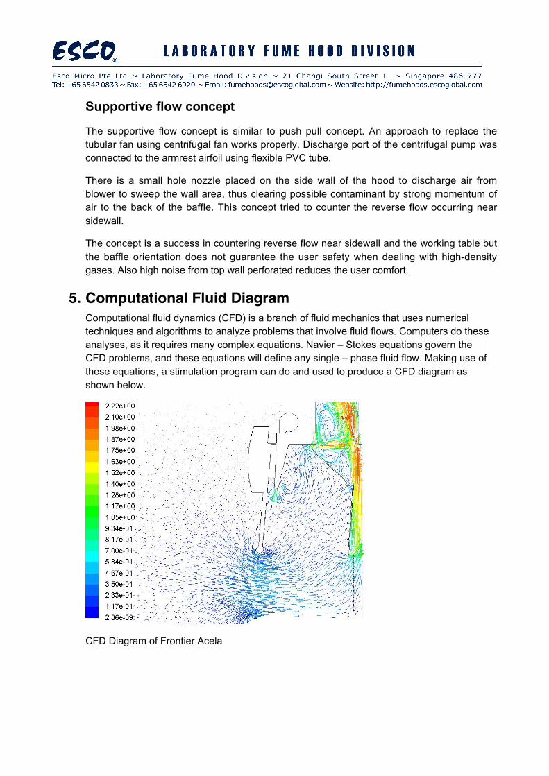
5. Computational Fluid DiagramComputational fluid dynamics (CFD) is a branch of fluid mechanics that uses numericaltechniques and algorithms to analyze problems that involve fluid flows. Computers do theseanalyses, as it requires many complex equations. Navier – Stokes equations govern theCFD problems, and these equations will define any single – phase fluid flow. Making use ofthese equations, a stimulation program can do and used to produce a CFD diagram asshown below.
CFD Diagram of Frontier Acela
6. Designing the ESCO Frontier AcelaFrontier Acela was designed to increase energy savings. To achieve this, operational facevelocity was reduce to 0.3 m/s (60 FPM).
Concepts and Ideas
After performing careful research by performing numerical calculation and literature study, itwas found that changes in design of baffle orientation, sash airfoil, armrest airfoil, exhaustcollar and bypass can increase the performance of Frontier Acela.
Compromise Solution(s)
The various features to support the concepts and ideas generated in previous stage areselected to meet the technical merit with regards to mechanical and manufacturability,electrical and electronic issues where the high reliability, humble and simple design are thefocus.
Aerodynamic designs of Frontier Acela
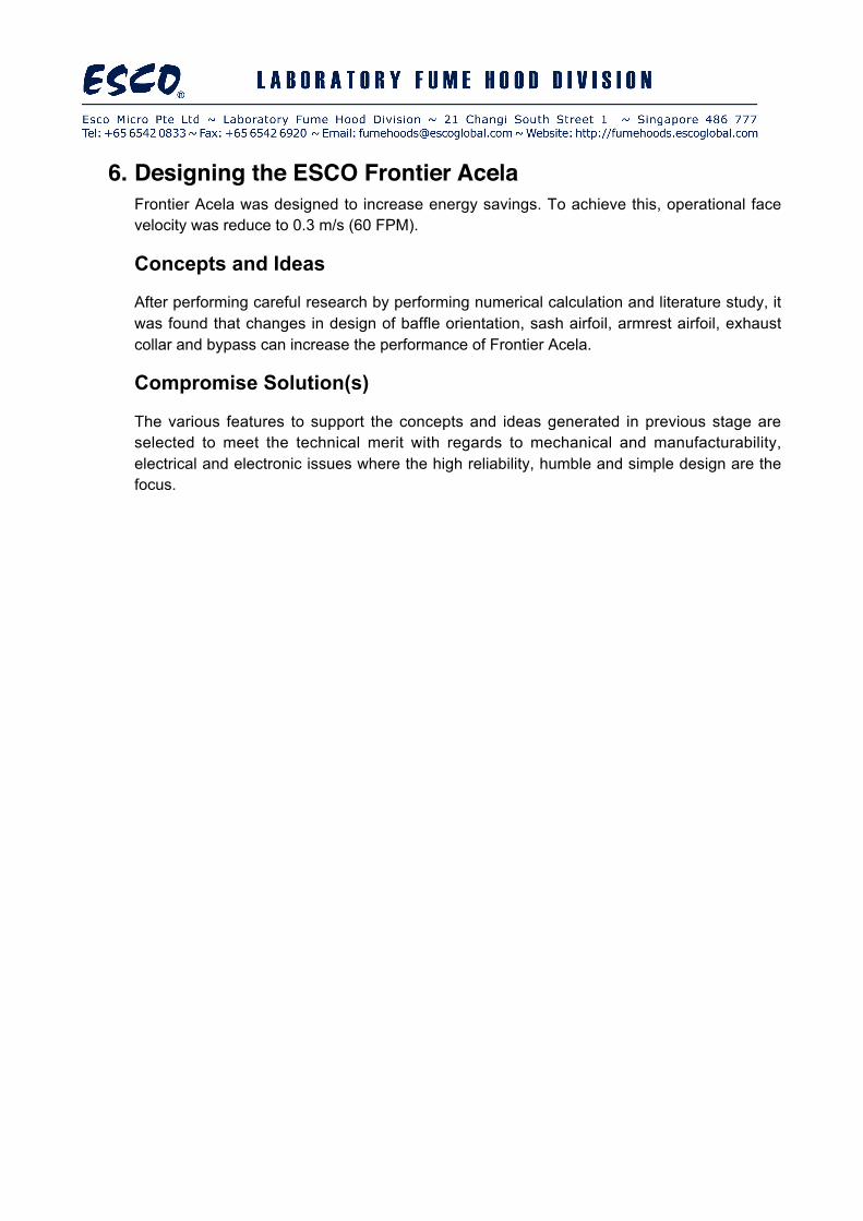
Baffle Orientation
The mid-baffle was inclined to meet therequirement when users deal with high-densitygases compared to air. The inclined baffleleads the flow into exhaust system smoothlywhere its inclined orientation avoid thepossibility of rolling inside the fume hoodchamber. A perforated down baffle is designedby the consideration to maintain sufficientnegative pressure for easy transportation ofhazardous gases and particles directly to theback of the baffle.
Sash Airfoil
Aerodynamic sash airfoil helps to reduce theturbulence intensity at the breathing zone. Theshape of airfoil was designed after muchtesting and numerical calculation with theobjective of avoiding vortex flow behind the
sash and reducing the turbulence intensity.
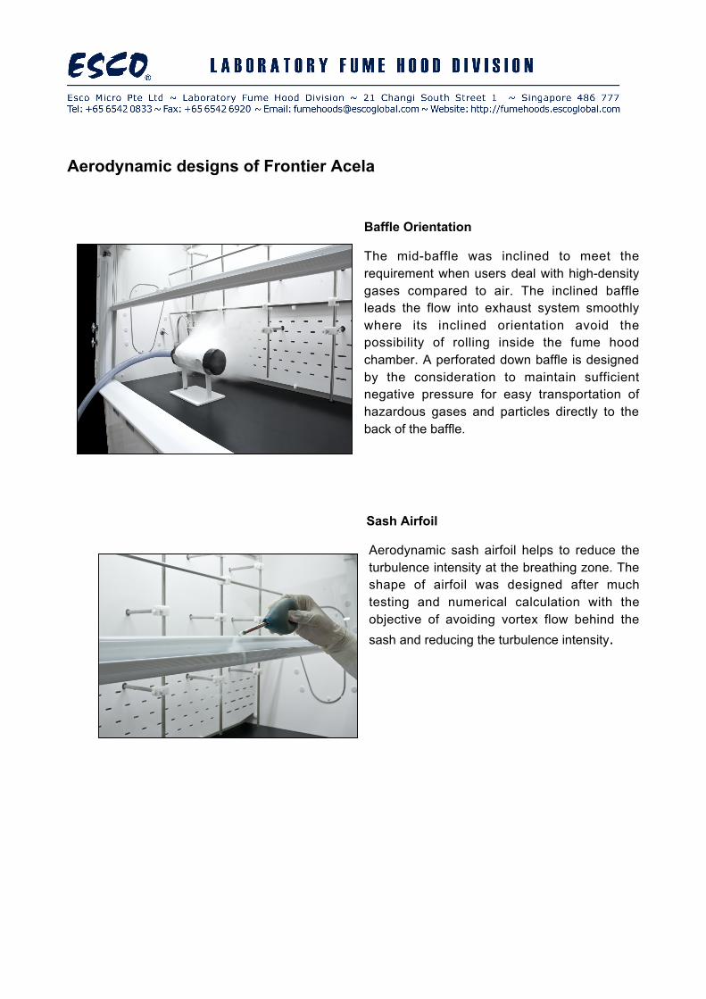
Armrest Airfoil
One of the most important features in afume hood is armrest airfoil. A correctlydesigned armrest airfoil enhances theflow characteristic entering the fumehood face by eliminating the vortexabove working table.
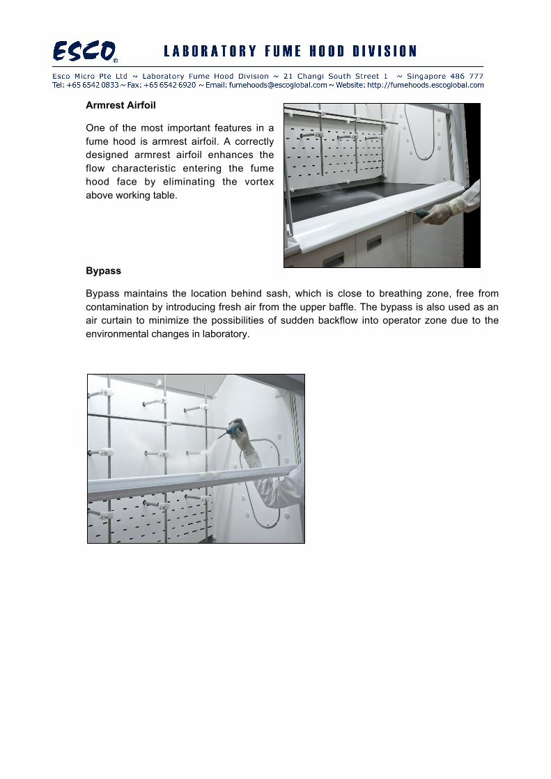
Bypass
Bypass maintains the location behind sash, which is close to breathing zone, free fromcontamination by introducing fresh air from the upper baffle. The bypass is also used as anair curtain to minimize the possibilities of sudden backflow into operator zone due to theenvironmental changes in laboratory.
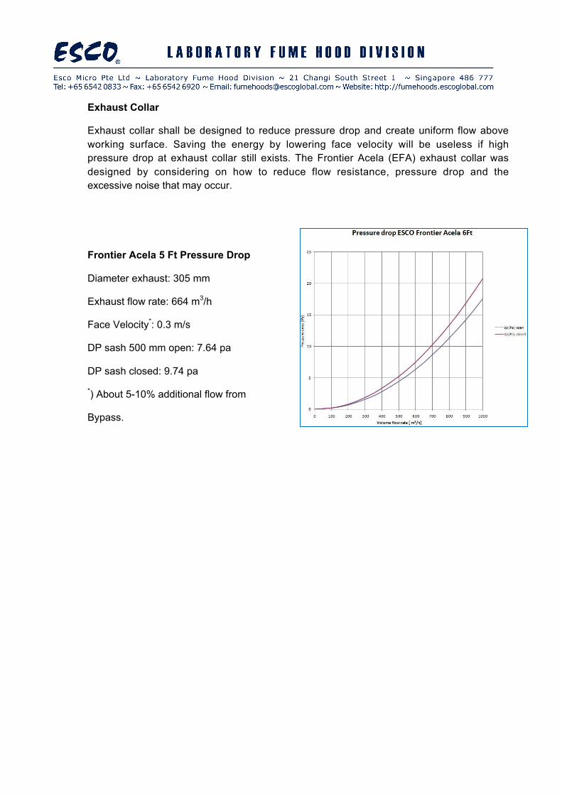
Exhaust Collar
Exhaust collar shall be designed to reduce pressure drop and create uniform flow aboveworking surface. Saving the energy by lowering face velocity will be useless if highpressure drop at exhaust collar still exists. The Frontier Acela (EFA) exhaust collar wasdesigned by considering on how to reduce flow resistance, pressure drop and theexcessive noise that may occur.
Frontier Acela 5 Ft Pressure Drop
Diameter exhaust: 305 mm
Exhaust flow rate: 664 m3/h
Face Velocity*: 0.3 m/s
DP sash 500 mm open: 7.64 pa
DP sash closed: 9.74 pa
*) About 5-10% additional flow from
Bypass.
Model and Prototype
The model was built to prove that the design meets the technical challenges. Variousfeatures were analyzed and summarized in protocol based on factory standard in quality,manufacturability, electrical and electronic.
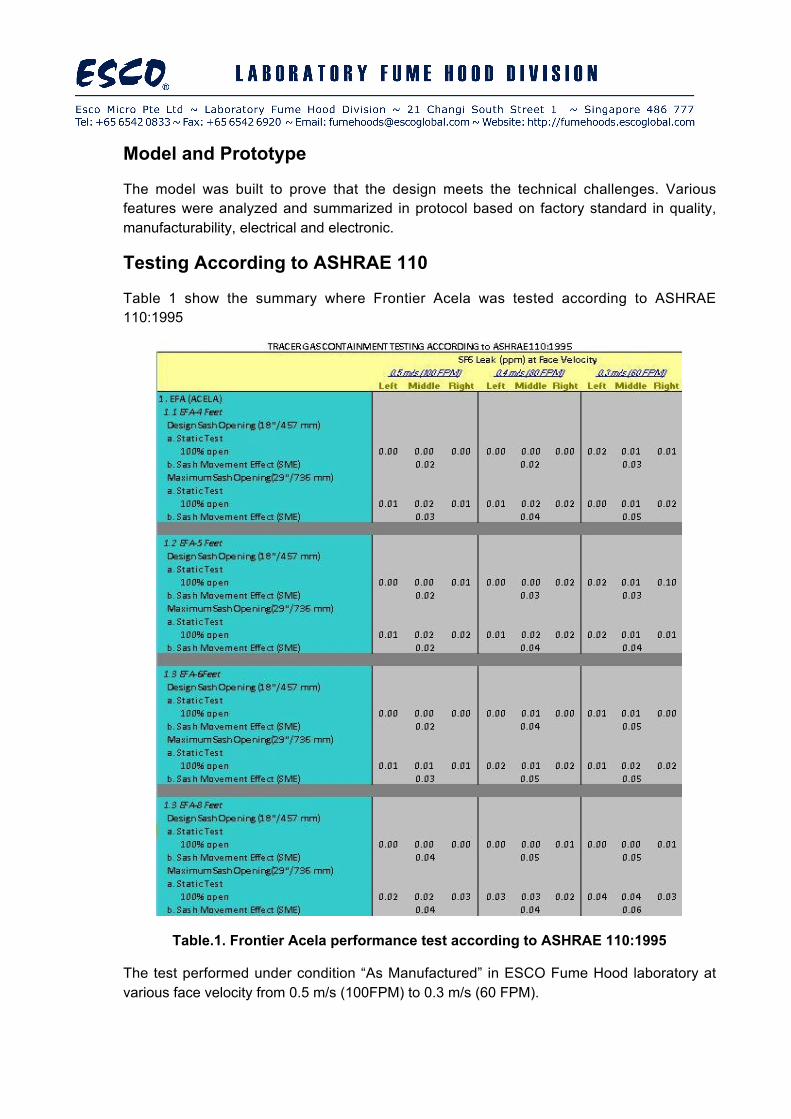
Testing According to ASHRAE 110
Table 1 show the summary where Frontier Acela was tested according to ASHRAE110:1995
Table.1. Frontier Acela performance test according to ASHRAE 110:1995
The test performed under condition “As Manufactured” in ESCO Fume Hood laboratory atvarious face velocity from 0.5 m/s (100FPM) to 0.3 m/s (60 FPM).
Testing According to EN14175
The test set-up of EN 14175 divided into outer grid test (OG), robustness test (RO) and theInner grid test (IG) as shown in Figure
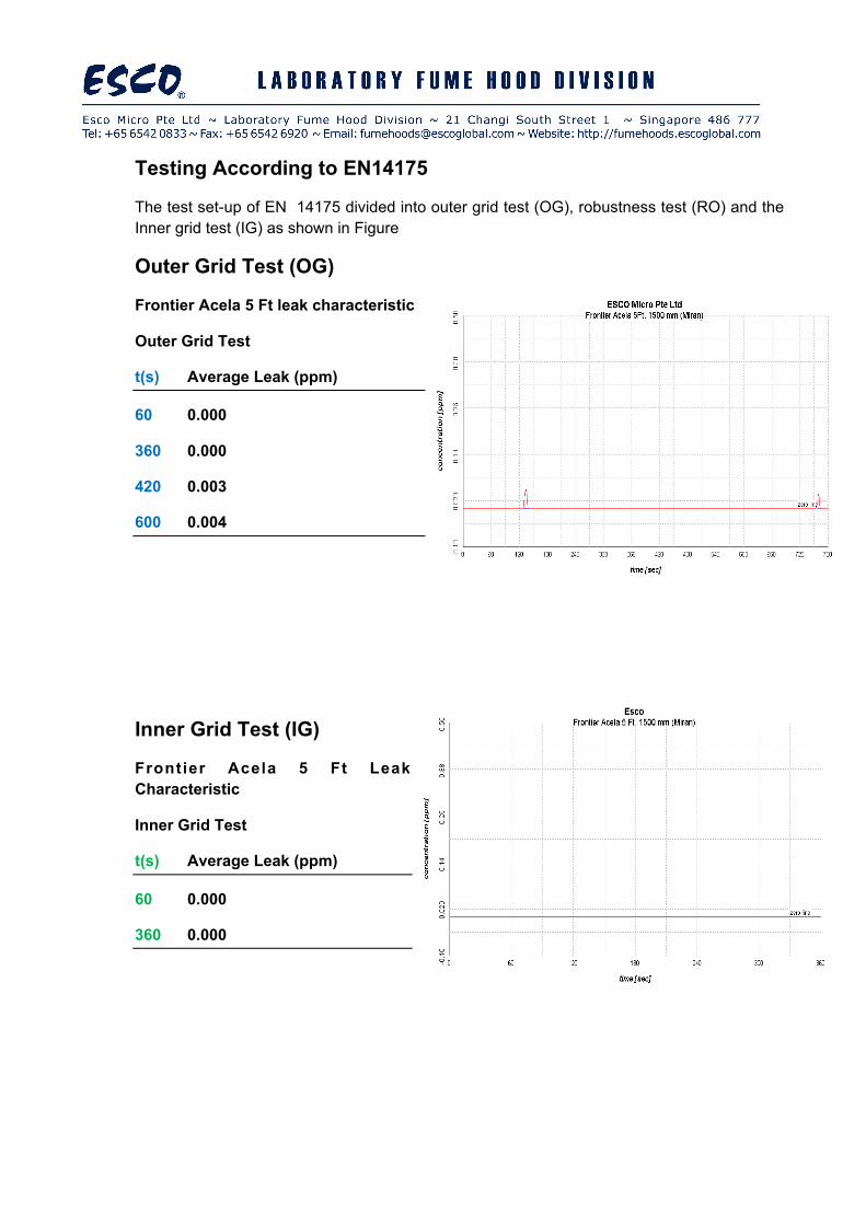
Outer Grid Test (OG)
Frontier Acela 5 Ft leak characteristic
Outer Grid Test
t(s) Average Leak (ppm)
60 0.000
360 0.000
420 0.003
600 0.004
Inner Grid Test (IG)
Frontier Acela 5 Ft LeakCharacteristic
Inner Grid Test
t(s) Average Leak (ppm)
60 0.000
360 0.000
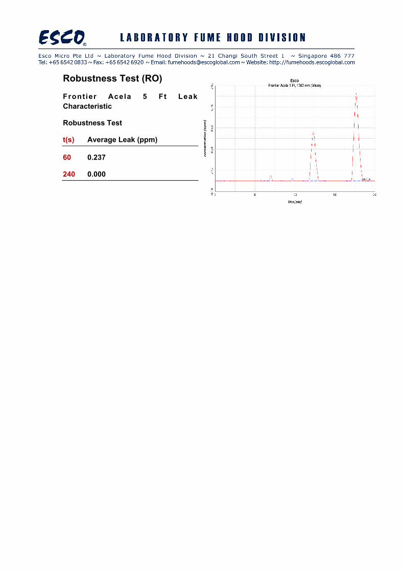
Robustness Test (RO)
Front ier Acela 5 Ft LeakCharacteristic
Robustness Test
t(s) Average Leak (ppm)
60 0.237
240 0.000
7. ConclusionTo increase Frontier Acela containment performance when operated at 0.3 m/s face
velocity, several ideas and concepts relating to fluid mechanics were developed and
applied as follows:
- Design aerodynamic Side Wall to avoid reverse flow where less aerodynamic design
will lead to failure.
- Proper design on sash handle airfoil eliminates separation at boundary edge, which
enhances protection to the operator breathing zone.
- Designing carefully and numerically on armrest airfoil was proven to increase the
protection to operator by countering flow separation above working table.
- Inclined middle baffle to enhance the reduction of vortex flow inside fume hood
chamber.
- Bypass from top baffle helps to reduce the risk of reverse blow into operator breathing
zone and also used as air curtain to protect sudden back flow due to the laboratory
environment change.
- Unique exhaust collar shape, statistically proven to reduction in pressure drop and
noise levels thus increase energy savings and uniformity of air stream above working
table.
Final prototype Frontier Acela 4Ft, 5Ft, 6Ft and 8Ft pass the performance test according to
ASHRAE 110:1995 The average leak was below the acceptance level of 0.05 ppm for
condition As Manufactured (AM) according to the protocol ASHRAE 110:1995. Frontier
Acela also pass the performance test according to EN 14175 (except the EFA 8Ft which
was not typically familiar in Europe Market, in this case EN14175 was not executed). The
average leak (see table below) pass the acceptance criterion where the value in Europe
(Especially in Germany) for Outer grid and robustness test shall be below 0.65 ppm, for the
inner grid test the acceptance value was referred to French standard that demands the
maximum leak is below 0.1 ppm.
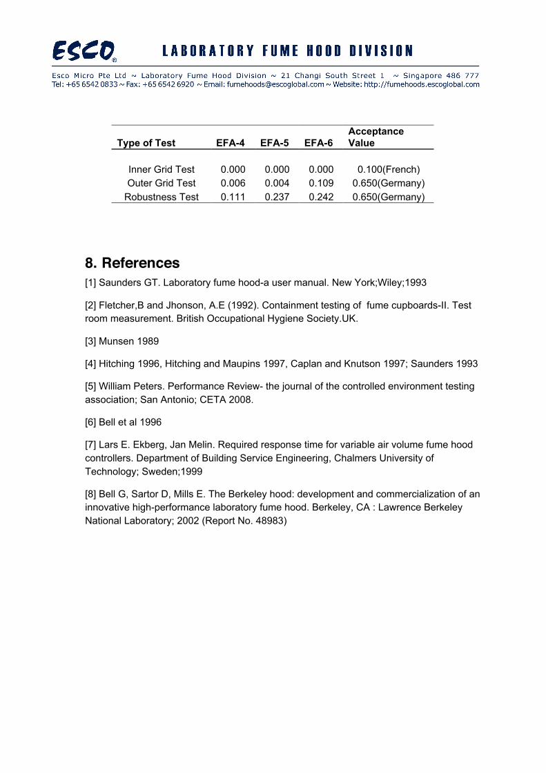
Type of Test EFA-4 EFA-5 EFA-6AcceptanceValue
Inner Grid Test 0.000 0.000 0.000 0.100(French)Outer Grid Test 0.006 0.004 0.109 0.650(Germany)
Robustness Test 0.111 0.237 0.242 0.650(Germany)
8. References[1] Saunders GT. Laboratory fume hood-a user manual. New York;Wiley;1993
[2] Fletcher,B and Jhonson, A.E (1992). Containment testing of fume cupboards-II. Testroom measurement. British Occupational Hygiene Society.UK.
[3] Munsen 1989
[4] Hitching 1996, Hitching and Maupins 1997, Caplan and Knutson 1997; Saunders 1993
[5] William Peters. Performance Review- the journal of the controlled environment testingassociation; San Antonio; CETA 2008.
[6] Bell et al 1996
[7] Lars E. Ekberg, Jan Melin. Required response time for variable air volume fume hoodcontrollers. Department of Building Service Engineering, Chalmers University ofTechnology; Sweden;1999
[8] Bell G, Sartor D, Mills E. The Berkeley hood: development and commercialization of aninnovative high-performance laboratory fume hood. Berkeley, CA : Lawrence BerkeleyNational Laboratory; 2002 (Report No. 48983)