Embed Size (px)
Citation preview

General rights Copyright and moral rights for the publications made accessible in the public portal are retained by the authors and/or other copyright owners and it is a condition of accessing publications that users recognise and abide by the legal requirements associated with these rights.
• Users may download and print one copy of any publication from the public portal for the purpose of private study or research. • You may not further distribute the material or use it for any profit-making activity or commercial gain • You may freely distribute the URL identifying the publication in the public portal
If you believe that this document breaches copyright please contact us providing details, and we will remove access to the work immediately and investigate your claim.
Downloaded from orbit.dtu.dk on: Sep 11, 2018
High-power green diode laser systems for biomedical applications
Müller, André; Petersen, Paul Michael; Andersen, Peter E.; Jensen, Ole Bjarlin
Publication date:2013
Document VersionPublisher's PDF, also known as Version of record
Link back to DTU Orbit
Citation (APA):Müller, A., Petersen, P. M., Andersen, P. E., & Jensen, O. B. (2013). High-power green diode laser systems forbiomedical applications. Kgs. Lyngby: Technical University of Denmark (DTU).

High-power green diode laser systems
for biomedical applications
Ph.D. thesis at the Technical University of Denmark
by
André Müller
Supervisors: Professor Paul Michael Petersen
Research Professor Peter Eskil Andersen
Senior Scientist Ole Bjarlin Jensen
DTU Fotonik, Department of Photonics Engineering
June, 2013


iii
Abstract
Due to their unique characteristics, diode lasers are increasingly attractive for
numerous applications. For example, in the biomedical field the provided output
power, spatial quality, and wavelength coverage of diode lasers has enabled their
applications in, e.g., dermatology, diffuse spectroscopy and imaging, and
fluorescence measurements. A major challenge in diode laser technology is to obtain
high-power laser emission at wavelengths < 600 nm. Especially the green spectral
range is of high importance, for example, in dermatology or for direct pumping of
ultrashort pulsed lasers in conjunction with optical coherence tomography, two-
photon microscopy or coherent anti-Stokes Raman scattering microscopy.
In order to provide high-power green diode laser emission, nonlinear frequency
conversion of state-of-the-art near-infrared diode lasers represents a necessary
means. However, the obtained output power of frequency doubled single emitters is
limited by thermal effects potentially resulting in laser degradation and failure. In
this work new concepts for power scaling of visible diode laser systems are
introduced that help to overcome current limitations and enhance the application
potential.
The underlying principle is spectral beam combining of multiple, comparable diode
lasers with subsequent nonlinear frequency conversion. In the former approach
multiple lasers are incoherently combined with an external optical component. With
two 1062 nm tapered diode lasers and a reflecting volume Bragg grating more than
16 W of output power at combining efficiencies > 93% are obtained. Utilizing the
wavelength tunability of diode lasers enables less critical optical alignment
compared to lasers limited to specific atomic transitions. It is shown that spectral
beam combining does not affect the beam propagation parameters and therefore
efficiently increases the brightness of compact and cost-effective diode laser
systems.
The condition of overlapping beams is an ideal scenario for subsequent frequency
conversion. Based on sum-frequency generation of two beam combined diode lasers
a 3.2 fold increase in visible output power compared to frequency doubling of a
single emitter is achieved. It is shown that nonlinear frequency conversion
significantly improves the spatial quality, which results in 3.9 W of diffraction-
limited green light at maximum performance.
In order to increase the output power even further, the developed concept is
expanded combining multiple diode lasers in a multiplexed grating. In case of three
diode lasers, the unique tunability allows for matching emission wavelengths of
simultaneous second harmonic generation and sum-frequency generation. The
obtained output power is given by the sum of the individual contributions and
indicates the potential for power scaling. Limited mainly by the acceptance
bandwidths of nonlinear crystals and the practical realization of multiplexed
gratings, this concept can be extended towards higher numbers of simultaneous

iv
nonlinear frequency conversions in advanced, visible, high-power diode laser
systems with increased application potential.
In order to prove the application potential of green diode laser systems a frequency
doubled tapered diode laser is applied for direct pumping of a mode-locked titanium
sapphire laser. The resulting pump efficiencies are reduced to 75% of the values
achieved with a commercial green solid state laser. However, due to a superior wall-
plug efficiency of the diode laser the overall efficiency of the titanium sapphire laser
is improved by a factor of 2. In mode-locked operation, a spectral bandwidth of
112 nm allows for sub-20 fs pulses and proves the potential for future diode based
compact and efficient titanium sapphire lasers.
Applying such a diode pumped titanium sapphire laser in optical coherence
tomography of the retina and skin shows similar results as obtained by solid state
pumped systems. Implementing the developed concept of frequency converted,
beam combined diode laser systems will help to overcome the high pump thresholds
for ultrabroad bandwidth titanium sapphire lasers, leading towards diode based high-
resolution optical coherence tomography with enhanced image quality.
In their entirety, the obtained results clearly strengthen the application potential of
diode lasers, including the biomedical field.

v
Abstrakt
Diodelasere er meget attraktive til mange anvendelser på grund af deres unikke
egenskaber. For eksempel i det biomedicinske område gør parametre som høj
udgangseffekt, god rumlig kvalitet og fleksibelt bølgelængde-område det muligt at
anvende diodelasere i for eksempel dermatologi, diffus spektroskopi og
billeddannelse eller fluorescensmålinger.
En stor udfordring i diodelaser teknologi er at opnå højt effekt ved bølgelængder
< 600 nm. Især lys ved grønne bølgelængder har stor betydning, for eksempel i
dermatologi eller til direkte pumpning af ultrakort pulsede lasere sammen med
optisk kohærens tomografi, to-foton mikroskopi eller kohærent anti-Stokes Raman
mikroskopi.
En egnet metode til at få høj effekt ved grønne bølgelængder er ikke-lineær
frekvenskonvertering af state-of-the-art infrarøde diodelasere. Desværre er
frekvensfordobling af enkelte emittere begrænset på grund af termiske effekter som
potentielt resulterer i dårligere performance eller ødelagte lasere. I dette arbejde
introduceres nye koncepter for effekt skalering af synlige diodelaser systemer, som
hjælper med at overvinde de nuværende begrænsninger og styrke anvendelses-
potentialet.
Det grundlæggende princip er inkohærent, spektral kombinering af flere
sammenlignelige diodelasere med efterfølgende ikke-lineær frekvenskonvertering.
Med to 1062 nm taperede diodelasere og et reflekterende volumen Bragg gitter er
der opnået mere end 16 W udgangseffekt ved en kombinationseffektivitet > 93%. I
forhold til lasere begrænset til bestemte atomare overgange tillader tuningen af
diodelaseres bølgelængde mindre kritisk optisk opligning. Det vises, at denne slags
inkohærent kombinering ikke påvirker den rumlige kvalitet af laseren og derfor
effektivt øger lysstyrken af kompakte og omkostningseffektive diodelaser systemer.
Den resulterende stråle bestående af to overlappende stråler er ideel til efterfølgende
frekvenskonvertering. Baseret på sum-frekvens generering af to kombinerede
diodelasere er der opnået en 3.2 gange forøgelse i synlig udgangseffekt i forhold til
frekvensfordobling af en enkelt emitter. Det vises også at ulineær
frekvenskonvertering forbedrer den rumlige kvalitet, hvilket resulterer i 3.9 W
diffraktionsbegrænset grønt lys ved maksimal strøm.
For at øge udgangseffekten yderligere, er det udviklede koncept udvidet til
kombinering af flere diodelasere i et gitter. Kombineres tre diodelasere kan
frekvensfordobling og sum-frekvens generering opnås samtidig og den unikke
tunebarhed af diodelasere tillader at generere de samme emissionsbølgelængder for
de to uafhængige processer. Den opnåede udgangseffekt er givet ved summen af de
enkelte bidrag og indikerer potentialet for effekt skalering. Dette koncept er mest
begrænset af den spektrale acceptans af ulineære krystaller og den praktiske
realisering af overlappende gitre og kan derfor anvendes til at udvide mod et højere
antal samtidige ikke-lineære konverteringer i avancerede, synlige, høj-effekt
diodelaser systemer med øget potentiale indenfor mange anvendelser.

vi
For at vise det fordelagtige i anvendelse af grønne diodelaser systemer, anvendes en
frekvensfordoblet taperet diodelaser til direkte pumpning af en mode-locked
titanium safir laser. Den resulterende pumpe effektivitet reduceres til 75% i forhold
til en kommerciel grøn faststoflaser. Imidlertid øger den høje elektro-optiske
effektivitet af diodelasere den samlede effektivitet af titanium safir laseren med en
faktor to. Mode-locking resulterer i en spektral båndbredde på 112 nm som tillader
sub-20 fs pulser og beviser potentialet for fremtidige diodelaser baserede kompakte
og effektive titanium safir lasersystemer.
Anvendelse af en diode-pumpet titanium safir laser i optisk kohærens tomografi af
nethinden og huden viser sammenlignelige resultater i forhold til kommercielle
systemer. Tilføjelse af de udviklede koncepter af frekvenskonverterede kombinerede
diodelaser systemer vil hjælpe med at overstige den høje pumpe tærskel for
ultrabredbåndede titanium safir lasere og føre til diodelaser baseret optisk kohærens
tomografi med høj opløsning og forbedret billedkvalitet.
I deres helhed styrker de opnåede resultater anvendelses-mulighederne af
diodelasere, herunder i det biomedicinske område.

vii
Preface
This thesis summarizes the results obtained during my Ph.D. project at DTU
Fotonik, Department of Photonics Engineering at the Technical University of
Denmark. The work was carried out between March 2010 and February 2013 under
supervision of Professor Paul Michael Petersen, Research Professor Peter Eskil
Andersen and Senior Scientist Ole Bjarlin Jensen. The project was mainly funded by
the PhD program at DTU Fotonik. In addition, equipment and travel expenses were
partially funded by the Danish Agency for Science, Technology and Innovation
(Grant number 09-076196), FP7 FUN OCT (HEALTH, 2008-12), FP7 FAMOS
(ICT, 2012-16), Otto Mønsted Fond, and Oticon Fonden.
During this project I performed the experimental work on spectral beam combining
of diode lasers with subsequent nonlinear frequency conversion. Furthermore, I
assisted in the development of compact diode laser based systems as pump sources
for titanium sapphire lasers and their application in optical coherence tomography.
This thesis was presented for public examination on June 14, 2013 at the Technical
University of Denmark. The evaluation committee consisted of Professor Michael
Drewsen (Aarhus University), Professor Edik Rafailov (University of Denmark),
and Professor Karsten Rottwitt (Technical University of Denmark). Minor
corrections have been made to the originally submitted thesis before printing.

viii

ix
Acknowledgement
I would like to take the chance and express my gratitude to my supervisors for their
trust, encouragement and support. It was a great pleasure to be part of your group
and I'm thankful for our fruitful discussions and for sharing your knowledge and
practical expertise. You made this an invaluable experience.
Within this project I had the opportunity to collaborate with colleagues in Berlin and
Vienna. I'm especially grateful to Götz Erbert and Bernd Sumpf from Ferdinand-
Braun-Insitut, Leibniz-Institut für Höchstfrequenztechnik in Berlin for providing me
with state-of-the-art diode lasers for my experimental work and their commitment
and helpful advice on technical and scientific matters.
Regarding the practical application of developed laser systems, I really enjoyed the
cooperation with colleagues at Femtolasers Produktions GmbH in Vienna. Here I
would like to thank Andreas Stingl and Tuan Le for their willingness to investigate
the application potential of green diode laser systems as direct pump sources for
titanium sapphire lasers.
I am also very thankful for the collaboration with our colleagues at the Medical
University of Vienna. I explicitly thank Wolfgang Drexler for the opportunity of
joint biomedical experiments and Angelika Unterhuber for her efforts implementing
and testing our light source in optical coherence tomography systems.
Finally, I would like to thank all my colleagues at DTU Fotonik for creating such an
excellent working atmosphere. I always felt welcome and it was a pleasure to work
with you.

x

xi
Table of contents
Abstract ..................................................................................................................... iii
Abstrakt ...................................................................................................................... v
Preface ..................................................................................................................... vii
Acknowledgement .................................................................................................... ix
List of publications.................................................................................................. xiii
List of abbreviations................................................................................................. xv
1. Introduction ........................................................................................................ 3
1.1. Key advantages of diode laser based systems ............................................ 3
1.2. Motivation for this work ............................................................................ 4
1.3. Structure of this thesis ................................................................................ 5
2. Diode lasers ........................................................................................................ 7
2.1. Basic principle of diode lasers ................................................................... 7
2.2. Vertical structure and edge-emitting laser devices ..................................... 8
2.3. Emission characteristics of diode lasers ................................................... 11
2.3.1. Power characteristics ........................................................................ 11
2.3.2. Spectral properties ............................................................................ 12
2.3.3. Spatial characteristics ....................................................................... 15
3. Frequency conversion ...................................................................................... 21
3.1. Basic concept of nonlinear frequency conversion .................................... 21
3.1.1. Frequencies of the induced polarization ........................................... 21
3.1.2. The nonlinear coefficient ................................................................. 22
3.1.3. Intensity of the generated wave ........................................................ 23
3.1.4. Pump depletion ................................................................................. 25
3.2. Phase-matching ........................................................................................ 26
3.2.1. Birefringent phase-matching ............................................................ 26
3.2.1. Quasi phase-matching ...................................................................... 28
3.2.2. Phase-matching tolerances ............................................................... 30
3.3. Boyd Kleinman analysis for frequency conversion .................................. 34
3.4. Nonlinear materials for generation of green light .................................... 35
3.5. Basic setups for frequency conversion ..................................................... 36

xii
4. Power enhancement by spectral beam combining............................................ 39
4.1. Beam combining of comparable lasers .................................................... 40
4.2. Spectral and angular acceptance............................................................... 41
4.3. Description of the experimental setup for beam combining ..................... 43
4.4. Characterization of the applied diode lasers ............................................. 44
4.5. Spectral beam combining of two DBR-tapered diode lasers .................... 46
5. Sum-frequency generation of spectrally combined diode lasers ...................... 49
5.1. Brief theoretical consideration ................................................................. 49
5.2. Experimental setup for sum-frequency generation ................................... 49
5.3. Frequency conversion of spectrally combined diode lasers ..................... 51
6. Extending the concept of spectrally combined diode lasers ............................. 59
6.1. Phase-matching for simultaneous SHG and SFG ..................................... 59
6.2. Theoretical description for simultaneous SHG and SFG ......................... 60
6.3. Setup for simultaneous nonlinear interactions ......................................... 61
6.4. Spectral beam combining in a multiplexed grating .................................. 62
6.5. Frequency conversion of three combined lasers ...................................... 64
7. Diode laser based pumping of titanium sapphire lasers ................................... 69
7.1. Direct pumping of Ti:sapphire lasers ....................................................... 69
7.2. Experimental setup for a diode based pump laser .................................... 70
7.3. Characterization of the diode based pump laser ....................................... 71
7.4. Experimental results for diode pumped Ti:sapphire lasers....................... 72
8. Diode pumped Ti:sapphire lasers for OCT ...................................................... 77
8.1. Optical coherence tomography ................................................................. 77
8.2. Diode based laser system for OCT measurements ................................... 78
8.3. OCT imaging with a diode pumped Ti:sapphire laser .............................. 79
Conclusion ............................................................................................................... 85
References ................................................................................................................ 87
Appendix .................................................................................................................. 97

xiii
List of publications
Peer-reviewed journal publications
1. O. B. Jensen, A. K. Hansen, A. Müller, B. Sumpf, A. Unterhuber, W.
Drexler, P. M. Petersen, and P. E. Andersen,
"Nonlinear frequency converted diode lasers for biophotonics,"
IEEE J. Sel. Top. Quantum Electron. 20, 7100515 (2013).
2. A. Unterhuber, B. Povazay, A. Müller, O. B. Jensen, T. Otto, I. Boettcher,
M. Duelk, R. Kessler, R. Engelhardt, M. Esmaeelpour, T. Le, P. E.
Andersen, C. Velez, G. Zinser, and W. Drexler,
"Simultaneous dual wavelength eye tracked ultrahigh resolution
retinal/choroidal OCT,"
Opt. Lett. 38, 4312-4315 (2013).
3. A. Müller, S. Marschall, O. B. Jensen, J. Fricke, H. Wenzel, B. Sumpf, and
P. E. Andersen,
"Diode laser based light sources for biomedical applications,"
Laser Phot. Rev. 7, 605-627 (2013).
4. A. Müller, O. B. Jensen, K.-H. Hasler, B. Sumpf, G. Erbert, P. E.
Andersen, and P. M. Petersen,
"Efficient concept for generation of diffraction-limited green light by sum-
frequency generation of spectrally combined tapered diode lasers,"
Opt. Lett. 37, 3753-3755 (2012).
5. A. Müller, O. B. Jensen, A. Unterhuber, T. Le, A. Stingl, K.-H. Hasler, B.
Sumpf, G. Erbert, P. E. Andersen, and P. M. Petersen,
"Frequency-doubled DBR-tapered diode laser for direct pumping of
Ti:sapphire lasers generating sub-20 fs pulses,"
Opt. Express 19, 12156-12163 (2011).
6. A. Müller, D. Vijayakumar, O. B. Jensen, K.-H. Hasler, B. Sumpf, G.
Erbert, P. E. Andersen, and P. M. Petersen,
"16 W output power by high-efficient spectral beam combining of DBR-
tapered diode lasers,"
Opt. Express 19, 1228-1235 (2011).

xiv
Conference proceedings
1. A. Müller, O. B. Jensen, K.-H. Hasler, B. Sumpf, G. Erbert, P. E.
Andersen, and P. M. Petersen,
"Efficient concept generating 3.9 W of diffraction-limited green light with
spectrally combined tapered diode lasers,"
Proc. SPIE 8604, 860404 (2013).
2. P. E. Andersen, O. B. Jensen, A. Müller, and P. M. Petersen,
"Green, Compact Diode Laser-based Systems for Biophotonics
Application,"
Asia Communications and Photonics Conference, OSA Technical Digest
(Optical Society of America, 2012), paper AS4E.1.
3. A. Müller, D. Vijayakumar, O. Jensen, K. Hasler, B. Sumpf, G. Erbert, P.
E. Andersen, and P. M. Petersen,
"Spectral beam combining of diode lasers with high efficiency,"
Lasers, Sources, and Related Photonic Devices, OSA Technical Digest
(Optical Society of America, 2012), paper AM4A.10.
4. A. Müller, O. B. Jensen, A. Unterhuber, T. Le, A. Stingl, K.-H. Hasler, B.
Sumpf, G. Erbert, P. E. Andersen, and P. M. Petersen,
"Frequency-doubled diode laser for direct pumping of Ti:sapphire lasers,"
Proc. SPIE 8235, 82351F (2012).
5. A. Müller, O. B. Jensen, A. Unterhuber, T. Le, A. Stingl, K.-H. Hasler, B.
Sumpf, G. Erbert, P. E. Andersen, and P. M. Petersen,
"Direct pumping of ultrashort Ti:sapphire lasers by a frequency doubled
diode laser,"
Proc. SPIE-OSA-IEEE Asia Communications and Photonics 8311, 831110
(2011).
Other contributions
1. O. B. Jensen, P. E. Andersen, P. M. Petersen, and A. Müller,
"Method of stabilizing a laser apparatus with wavelength converter,"
Patent application PCT/EP2012/054338 (2012).
2. A. Müller, O. B. Jensen, P. E. Andersen, and P. M. Petersen,
"Efficient generation of 3.9 W of diffraction-limited green light with
spectrally combined tapered diode lasers,"
Oral presentation at Northern Optics 2012.

xv
List of abbreviations
CW Continuous Wave
RW Ridge-Waveguide
BA Broad Area
TA Tapered Amplifier
DBR Distributed Bragg Reflector
DFB Distributed Feedback
COMD Catastrophic Optical Mirror Damage
DPSS Diode Pumped Solid State
SHG Second Harmonic Generation
SFG Sum-Frequency Generation
QPM Quasi Phase-Matching
LN Lithium Niobate
PPLN Periodically Poled Lithium Niobate
AR Antireflection
NA Numerical Aperture
FWHM Full Width at Half Maximum
SBC Spectral Beam Combining
PTR Photo-Thermo-Refractive
VBG Volume Bragg Grating
DE Diffraction Efficiency
OCT Optical Coherence Tomography

xvi

This page intentionally left blank


To my parents,
Elke and Thomas
And to Anne,
for your sacrifices, patience, and love

3
1. Introduction
1.1. Key advantages of diode laser based systems
In 1960 Theodore Maiman demonstrated the first practical realization of a laser [1].
Since then the range of laser applications has increased enormously. Among the
different types especially diode lasers became and are increasingly attractive.
Compared to optically pumped lasers, such as diode pumped solid state lasers [2],
diode lasers are electrically pumped and are by far the most efficient light sources
currently available [3],[4]. In addition, chip technology enables to manufacture
diode lasers at low cost and in high numbers. Dimensions of a few mm3 allow for
realization of compact laser systems, increasing their application potential.
In the biomedical field the applications of diode based laser systems range from
diagnostics and imaging applications, such as optical coherence tomography [5],
fluorescence lifetime imaging [6], diffuse optical imaging [7], THz imaging [8] or
laser Doppler imaging [9], to direct treatments, such as photocoagulation [10],
photo-dynamic therapy [11] or biomodulation/bioactivation [12]. A more detailed
review explaining the impact of diode lasers on selected biomedical applications is
given in [13].
The application potential of diode lasers is strongly related to their emission
properties. Regarding the continuous wave (CW) output power of edge-emitting
diode lasers, several watts with nearly diffraction-limited beams are obtained with
ridge-waveguide (RW) and tapered diode lasers [14],[15]. At the expense of spatial
quality the output power can be increased even further with broad area (BA) diode
lasers or diode laser bars and stacks [16],[17]. Additional optical feedback may help
to improve the poor spatial properties of these devices [18]. With techniques such as
mode-locking or gain-switching, diode lasers can also be operated in pulsed mode,
resulting in picosecond pulses with repetition rates in the GHz range [19],[20].
Special types of diode lasers excluded from this work are vertical cavity surface
emitting lasers. They are characterized by laser emission normal to the substrate
surface and low threshold currents [21]. The limiting factor towards high-power
emission with good spatial quality is the heat removal from the short active region
[22].
Unlike lasers limited to specific atomic transitions, a much wider spectral range of
400 nm - 2 µm can be accessed by engineering the material composition of diode
lasers [23]. Within the gain bandwidth the emission wavelengths can be tuned by
injection current or laser temperature [21]. While spectral side-modes are suppressed
at higher injection currents [24], improved single-mode emission can be obtained by
intrinsic or external feedback [24],[25]. The latter also enables wavelength tuning
over several tens of nanometers [26]. Wavelengths not obtained with current
technology can be accessed by nonlinear frequency conversion [27]. This also

4
enables to increase the output power in certain regions such as the green spectral
range where obtaining high-power diode laser emission is still challenging.
All aspects such as output power, spatial quality, wavelength coverage and
tunability, efficiency, size and production cost, are the reasons for diode laser
technology being versatile and increasingly applicable, including the biomedical
field.
1.2. Motivation for this work
For all laser applications certain laser parameters need to be fulfilled. As discussed
above, diode lasers have proven their superior performance in many of these aspects.
Figure 1 gives an overview on the obtained maximum output power (CW) of edge-
emitting diode lasers within a spectral range of 300 nm - 1200 nm [13]. Within that
range the highest output powers are obtained at near-infrared wavelengths. For
example, up to 25 W were achieved with BA lasers between 800 nm - 1000 nm [28].
These lasers are ideally suited for dermatological applications, where output power,
emission wavelength and absorption by blood are the key parameters.
Figure 1: Overview on CW-output power versus emission wavelength
reported for BA, RW and tapered diode lasers [13]. The striped
rectangular shape between 500 nm and 600 nm indicates one current
major challenge in diode laser technology, i.e., obtaining > 1 W of direct
laser emission in the green-yellow spectral range.
In the visible spectral range up to 5.6 W were reported for red-emitting BA lasers
[29]. Due to their size, efficiency, and low power requirements, red diode lasers are
preferred for applications such as diffuse spectroscopy and imaging. At blue
emission wavelengths up to 1.6 W were obtained [30], applicable in fluorescence
measurements that typically require low power laser emission.

5
A major challenge in diode laser technology is to obtain high-power emission in the
green and yellow spectral range, as indicated by the marked region in Figure 1.
Especially green lasers are of high importance in the biomedical field, for example,
in dermatology or as direct pump sources of ultrashort pulsed lasers, see below.
Nonlinear frequency conversion represents a necessary means to meet this
challenge. State-of-the-art 1062 nm tapered diode lasers were reported with up to
12 W of output power and good spatial qualities [31]. These lasers have been shown
to be very well suited for efficient, high-power frequency conversion, resulting in
1.58 W of green light [32]. At this level, green diode lasers have a competitive
application potential in direct pumping of titanium sapphire (Ti:sapphire) lasers,
required for biomedical applications such as two-photon microscopy [33], coherent
anti-Stokes Raman scattering microscopy [34], or optical coherence tomography
[35]. However, higher performance is required in order to overcome increased pump
thresholds for ultrabroad bandwidth Ti:sapphire lasers in high-resolution OCT
systems or to address other applications such as photocoagulation in conjunction
with vascular diseases [36],[37],[38]. Unfortunately, increasing the output power of
single emitter systems is limited by undesired heat effects that may lead to laser
failure. The motivation for this work is to overcome these limitations and develop
state-of-the-art high-power green diode laser systems. Based on spectral beam
combining of comparable lasers and subsequent nonlinear frequency conversion, the
developed concepts utilize the unique characteristics of diode lasers and
significantly increase the performance of visible diode laser systems by individual or
simultaneous nonlinear interactions.
A second motivation is to prove the competitiveness of green diode laser systems in
the biomedical field by applying them as direct pump sources for Ti:sapphire lasers
in optical coherence tomography (OCT) measurements.
1.3. Structure of this thesis
In the beginning, the chapters 2 and 3 provide a theoretical overview on diode lasers
and nonlinear frequency conversion. Based on the example of tapered diode lasers
used throughout the work, the basic principle of diode lasers, their vertical structure,
and the emission characteristics of diode lasers are discussed.
The large field of nonlinear frequency conversion in this work is restricted to 2nd
order phenomena, more precisely, second harmonic generation and sum-frequency
generation. The overview on frequency conversion includes the basic concept
behind these nonlinear phenomena, a brief discussion of well-established phase-
matching techniques, and Boyd-Kleinman theory regarding the optimum focusing
condition. All theoretical examples are based on lithium niobate crystals as applied
in this work. In addition, alternative nonlinear materials for green light generation
and different approaches towards frequency conversion are briefly discussed.

6
The second part of this thesis summarizes the obtained experimental results. While
chapter 4 describes the concept of spectral beam combining, chapter 5 discusses the
utilization of this concept in generating multiple watts of green light by efficient
sum-frequency generation of spectrally combined diode lasers. Chapter 6 illustrates
how multiplexed gratings can be applied in order to efficiently extent this new
concept, generating visible laser emission from simultaneous nonlinear interactions.
The final two chapters focus on the application potential of green diode laser
systems. While chapter 7 shows the results obtained with direct pumping of
ultrashort pulsed Ti:sapphire lasers, chapter 8 summarizes the results achieved in
OCT measurements of the retina and skin with a diode pumped Ti:sapphire laser
system.
A summary of the obtained results and brief outlooks on power scaling of future
visible diode laser systems and their application in OCT measurements concludes
this work.

7
2. Diode lasers
2.1. Basic principle of diode lasers
Compared to other laser types with sharp energy levels, diode lasers are based on
broad energy bands. The lower band referred to as the valance band and the upper
band referred to as the conduction band are separated by a band gap with the energy
Eg. The band gap energy of typical III-V compound semiconductors is in the range
of 0.5 eV - 2.5 eV, depending on the material composition. Based on the following
relation [21]
(1)
the available emission wavelengths λ range from the blue to the near-infrared [23].
Here EPhoton is the photon energy, h the Planck constant (h = 4.135·10-15
eVs), ν the
frequency, and c the vacuum speed of light (c = 3·108 m/s).
Without external excitation and at a temperature of T = 0 K, the valance band of
undoped semiconductors is occupied with electrons while the conduction band is
empty. Applying an injection current to the diode increases the concentrations of
electrons in the conduction band and electron holes in the valence band. The
generation and recombination of these electron-hole pairs enables band to band
transitions (Figure 2).
Figure 2: Illustration of three possible band-to-band transitions in diode
lasers. While spontaneous and stimulated emissions are caused by
recombination of electrons and holes, photon absorption can generate new
pairs of electrons and holes.
Spontaneous recombination of electrons and holes results in emission of photons
that are random in direction and phase. This principle is utilized in light-emitting
diodes. The emitted photons can be absorbed to generate new pairs of electrons and
holes. The third transition mandatory for laser operation is stimulated emission.
Generated photons stimulate recombination of additional electrons and holes,
resulting in simultaneous generation of additional photons that are coherent with the
initial photons. In order to obtain an operating laser the stimulated emission needs to

8
be amplified, compensating losses such as photon absorption. This is referred to as
threshold condition. It is obtained by population inversion, i.e., the number of
electrons in the conduction band needs to exceed the number in the valence band,
and by positioning the laser medium inside a resonant cavity providing optical
feedback. For diode lasers the cavity is typically constructed between the coated end
facets of the diode. While the rear facets typically show high reflectivities
(Rr > 90%), the high gain of diode lasers allows for front facets that can be anti-
reflection coated (Rf 1%) [31].
2.2. Vertical structure and edge-emitting laser devices
The basic elements for diode lasers are a medium providing optical gain by
stimulated emission, a resonant cavity for optical feedback, an optical waveguide
confining the photons to the active region, and lateral confinement of photons,
injection current and carriers [21]. Most diode lasers are based on p-i-n double
heterostructures consisting of an un-doped semiconductor layer embedded between
p- and n-doped semiconductors with higher band gaps (Figure 3). This structure has
the advantage that injected carriers are confined between the barriers in the
conduction and valence bands. The intrinsic layer therefore acts as the active region
providing optical gain. In addition, the lower refractive indices of larger band gap
semiconductors result in optical wave guiding in vertical direction.
Figure 3: Energy band diagram of a p-i-n double heterostructure. This type
of structure enables carrier confinement between the barriers of p- and n-
doped semiconductors and provides optical wave guiding in vertical
direction.
The active region can be based on a number of quantum wells or quantum dots.
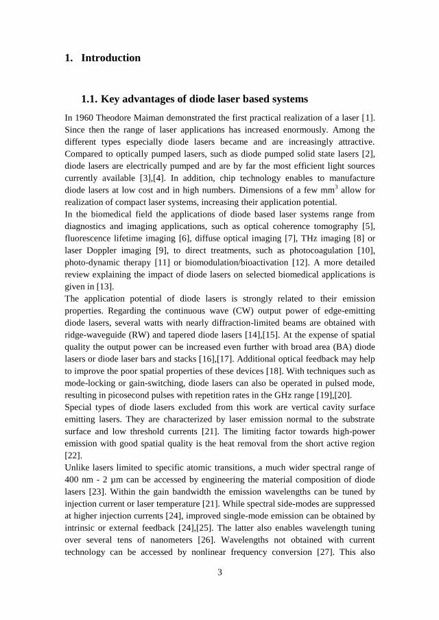
Figure 4 shows the vertical layer structure of 1062 nm diode lasers applied in this
work. The active region of these lasers is composed of a triple indium gallium
arsenide (InGaAs) quantum well in a super large optical cavity [15]. Super large
9
optical cavities are characterized by a few micron high waveguide cores that reduce
the vertical far field divergence [39], posing a potential issue when collimating the
laser emission. The high number of quantum wells compensates the related
reduction of the overlap between the optical field and the active region, improving
the efficiency of the lasers [15].
Figure 4: Vertical layer structure of diode lasers based on the example of
1062 nm diode lasers as applied in this work [40]. The active region is
sandwiched between p- and n-side aluminum gallium arsenide (AlGaAs)
waveguides surrounded by cladding layers. A highly doped contact layer
completes the p-side.
The vertical layer structures of diode lasers are grown by different techniques such
as metal organic vapour phase epitaxy [41] or molecular beam epitaxy [42].
Afterwards these structures are processed into different laser devices. First the stripe
width is defined along which the light is gain- or index-guided in lateral direction of
the device.
Gain-guiding is enabled by defining a current aperture in the contact layer that
spatially limits the carrier injection [21]. Optical waves outside this aperture
experience high losses, resulting in lateral confinement of generated laser emission.
Gain-guiding is typical for BA lasers where stripe widths of a few hundred microns
enable tens of watts of output power [43]. Several emitters can be combined within a
laser bar to increase the output power even further [17]. One disadvantage of such
BA lasers is the poor spatial quality of their emission, caused by high-order lateral
modes in the wide active region [44].
A better spatial quality is obtained in index-guided devices. Index-guiding is based
on an induced refractive index step in lateral direction. The resulting ridge provides
additional wave guiding in lateral direction [21]. The spatial mode characteristic of a
three-layer waveguide is determined by the normalized waveguide thickness D [24],
given by

10
√
(2)
Here d represents the core dimension of the waveguide and n the refractive index. In
such a waveguide single mode propagation is obtained at D < π. In diode lasers this
condition is typically satisfied in vertical direction. By optimizing the width and
etching depth of the ridge, index-guided lasers potentially enable single lateral mode
emission. Index-guiding is typical for a few microns wide RW lasers providing
output powers of a few watts [14].
In addition to gain- and index-guiding that provide current and optical confinement,
respectively, buried heterostructures also provide carrier confinement. This prevents
a lateral diffusion of carriers by introducing additional current blocking layers and
therefore lowers the laser threshold [21].
The most promising concept towards high output power and improved spatial
quality is the tapered laser [45]. In these devices laser emission from a RW section is
monolithically coupled into a flared section, acting as a passive amplifier. This
tapered amplifier (TA) is typically gain-guided. The mode-area in the flared section
broadens at an angle chosen with respect to the diffraction of the beam leaving the
RW. Therefore, the tapered section amplifies the emission while maintaining the
single lateral mode profile provided by the ridge-waveguide. Based on the above
shown vertical structure, 6 mm long distributed Bragg reflector (DBR)-tapered
diode lasers were reported with up to 12 W and nearly diffraction-limited beams
[31]. The layout of a DBR-tapered diode laser applied in this work is illustrated in
Figure 5. The 6 mm long diode laser consists of a 1 mm passive DBR grating
serving as wavelength selective rear side mirror, a 1 mm RW section and 4 mm TA
with a tapered angle (TA) of 6°. The injection currents to the RW and TA are
controlled separately, enabling independent control of output power, spatial quality,
and spectral behavior [31]. A more detailed explanation of the intrinsic DBR grating
is given in section 0.
Figure 5: Layout of a DBR-tapered diode laser as applied in this work.
After the processing and metallization of diode lasers they are cut according to the
desired length and their facets are coated. The lasers are then mounted on heat
spreaders and different actively or passively cooled mounts. A common approach is
p-side down mounting to lower the thermal resistance [46]. Long lasers with
reduced thermal resistance also enable p-side up mounting to lower mounting
induced stress [31]. In order to enable separate control of the RW and TA without

11
using structured contacts the lasers applied in this work are mounted p-side up on a
copper tungsten heat spreader. The heat spreader itself is mounted on a conduction
cooled package mount with a 25 mm x 25 mm footprint.
2.3. Emission characteristics of diode lasers
2.3.1. Power characteristics
In lasers the generated emission needs to be amplified by stimulated emission in
order to compensate all losses occurring within the resonant cavity. For a Fabry-
Pérot resonator, consisting of two mirrors separated from another by the length L,
this threshold condition [21] is expressed by
(
) (3)
Here gth represents the modal gain, given by the product of the threshold material
gain gth and the confinement factor . The latter depends on the overlap of the
optical mode-pattern with the active region of the diode laser. αmirror represents the
combined photon losses at the diode laser end facets and αi the losses by intrinsic
absorption, respectively. The reflectivities of the end facets are expressed by R1, and
R2. It can be seen that the threshold is reduced by increasing the length of the gain
medium and the reflectivities of the resonant cavity. However, choosing the proper
reflectivities is crucial with respect to performance and lifetime.
Once the threshold condition is obtained, the output power P shows a linear
dependence on the injection current I [21], according to
( )
( ) (4)
Here ηi represents the internal efficiency, i.e., the fraction of the injection current
generating carriers in the active region. q is the elementary charge of electrons
(q = 1.602·10-19
C), Ith the threshold current and ηd the differential efficiency. The
latter defines how many photons are generated with respect to the injected electrons
per time and is given by
(5)
Here dP/dI is the slope efficiency in W/A. Figure 6 shows a typical power current
characteristic for a 1062 nm DBR-tapered diode laser as introduced above. The laser
is operated at a laser temperature of T = 20 °C and an injection current to the ridge
section of IRW = 300 mA. The injection current to the tapered amlifier (ITA) is
increased in 1 A steps. The measurement shows a threshold current of 2 A. The
maximum output power of 10.8 W at 16 A results in a slope efficiency of 0.8 W/A.

12
The corresponding wall-plug efficiency, i.e., the electro-optical efficiency, is in the
range of 30%.
Despite high wall-plug efficiencies [3],[4], the output power of diode lasers is
mostly limited by heat effects. Increased temperatures in the active region reduce the
carrier confinement and increase the amount of non-radiative recombinations [47].
These effects increase the threshold current and lower the differential efficiency.
This potentially causes a reversible thermal rollover in the power-current
characteristics before the diode lasers are destroyed by catastrophic optical mirror
damage (COMD). Without COMD the lifetimes of diode lasers can exceed 10,000 h
[48]. In Figure 6 it can be seen that the 1062 nm DBR-tapered diode lasers do not
show signs of thermal rollover or COMD within the specified current range.
Figure 6: Power current characteristic of a 1062 nm DBR-tapered diode
laser at T = 20 °C and IRW = 300 mA.
2.3.2. Spectral properties
As mentioned above, laser operation requires optical feedback in resonant cavities of
the length L. Resonant feedback in a Fabry-Pérot resonator is based on the
development of standing waves. This requires
(6)
with m being the order number of the longitudinal modes (m = 1, 2, 3, ...), λ0 the
vacuum wavelength, and neff the effective refractive index of the waveguide inside
the diode laser [21]. Fabry-Pérot resonators allow multiple longitudinal modes
separated by the free spectral range. In a gain medium above threshold only the
longitudinal modes closest to the maximum modal gain are amplified. In diode
lasers a gain-spectrum wider than the FSR enables multimode emission [24].

13
Although side-modes are to some extent suppressed at high injection currents,
additional techniques are required in order to obtain single-mode emission preferred
for certain applications. For example, the emission spectra of diode lasers can be
narrowed by external or internal gratings. In external cavity configurations an anti-
reflection coated facet enables wavelength selective optical feedback provided by an
external grating [49]. Two well-established techniques are Littrow and Littman-
Metcalf configurations. In a Littrow configuration the first order diffraction of a
flexible external grating is coupled back to the diode [25]. In Littman-Metcalf
configurations a combination of a fixed grating and a flexible mirror are used
[50],[51]. Both configurations enable wavelength tuning over several tens of
nanometers [26].
Compared to these external approaches, distributed feedback (DFB)-lasers or DBR-
lasers provide intrinsic wavelength stabilization. In DFB-lasers the feedback is
distributed throughout the device by introducing periodic perturbations of the
refractive index along the length of the active region [52]. The underlying principle
for selective feedback is Bragg scattering. The Bragg condition
(7)
with Λ being the grating period, θ the angle of incidence, m the order of Bragg
diffraction (m = 1, 2, 3, ...), and λB the Bragg wavelength [53], implies that counter
propagating waves inside the cavity couple coherently only at Λ = mλB/2 [24].
Proper engineering of the grating period consequently provides selective feedback,
resulting in spectral single-mode emission. In DBR-lasers Bragg scattering is limited
to regions beyond the active region and the passive intrinsic gratings act as
wavelength selective mirrors of the resonator [54].
The DBR-tapered diode lasers applied in this work are based on 6th
-order surface
gratings with periods of about 1 µm and duty cycles of 0.9 [15],[55]. The gratings
are produced by stepper lithography. Compared to low order gratings these high
order gratings are characterized by a lower number of reflecting elements (grooves).
The low number of grooves reduces the reflectivity which can be compensated by
optimizing the duty cycle [15]. In addition a low number of grooves allows for
further simplification of the fabrication process suitable for cost-effective mass
production [56]. It is also assumed that a resulting improvement of the overlap of the
fundamental mode with the grating and reduced scattering losses compensate the
reduced reflectivity of these gratings. In order to solely provide optical feedback
from the intrinsic gratings, the rear facets of the applied lasers are anti-reflection
coated (Rr < 10-3
%). The front facets have a reflectivity of Rf = 0.5%.
Figure 7 shows a typical spectrum of a 1062 nm DBR-tapered diode laser at
T = 20 °C, IRW = 300 mA, and ITA = 16 A. All spectra in this work are measured
with an optical spectrum analyzer (Advantest Q8347) that has a maximum resolution
of 1 pm - 10 pm within a wavelength range of 500 nm - 1550 nm, respectively, and a
dynamic range of 35 dB. Due to the intrinsic wavelength stabilization spurious

14
spectral modes are not reflected back into the tapered section, resulting in a
significantly narrowed spectral width of ΔλFWHM 10 pm. In addition, a side-mode
suppression ≥ 20 dB is obtained.
Figure 7: Spectrum of a 1062 nm DBR-tapered diode laser at T = 20 °C,
IRW = 300 mA, and ITA = 16 A. The inset shows the same spectrum on a
logarithmic scale. FWHM: abbreviation for full width at half maximum.
Figure 8: Emission wavelength of a 1062 nm DBR-tapered diode laser
versus injection current (bottom-left) and temperature (top-right),
measured at 20 °C or at ITA = 16 A, respectively.
One unique characteristic of diode lasers is an emission wavelength tunable with
temperature or injection current [21]. Both mechanisms affect the length of the
device as well as the temperature dependent refractive index, shifting the emission

15
wavelength according to equation (6). Figure 8 illustrates that the emission
wavelength of a 1062 nm DBR-tapered diode laser changes with approximately
0.03 nm/A and 0.08 nm/K, respectively. This feature enables wavelength tuning
applicable in applications such as frequency conversion or beam combining.
2.3.3. Spatial characteristics
Due to the facet dimensions of diode lasers and diffraction at the facets, laser
emission leaving the resonator diverges differently in both transverse directions,
which results in elliptical emission profiles. The narrow waveguides in vertical
direction result in large divergence angles. The corresponding axis is referred to as
fast axis. The lateral direction is referred to as slow axis and shows a reduced
divergence.
Depending on the lateral structure, diode lasers can additionally show astigmatic
laser emission (Figure 9). For example, beams along the fast axis of tapered diode
lasers experience vertical wave-guiding and diverge from the laser facet. Beams
along the slow axis experience diffraction when coupled into the TA. This results in
curved wave fronts in lateral direction. Due to this lateral curvature and diffraction
at the laser facet, slow axis beams seem to originate from a virtual source inside the
device [57]. The distance of that virtual source to the laser facet is referred to as
astigmatism, approximately given by the ratio of the tapered amplifier length and its
refractive index (L/neff) [23]. For example, the astigmatism of the applied 1062 nm
DBR-tapered diode lasers is in the range of 1.4 mm.
The astigmatism of tapered diode lasers slightly increases with the injection current,
probably caused by changes in the transverse refractive index profile [23],[44]. Most
applications such as frequency conversion preferably require collimated laser
sources with circular emission profiles and corrected for astigmatism. In practice
this is often obtained by collimating the two axes separately and operating the laser
at a fixed or maximum current. The power available for further experiments can then
be adjusted, e.g., by using a waveplate and a polarizer.
Figure 9: Side and top view of an astigmatic beam emitted by a tapered
diode laser. Using a lens, the beam is collimated in the fast axis but
focused to a waist in lateral direction. An additional cylindrical lens can be
applied to collimate the beam along the slow axis as well.
An additional important parameter of lasers is the beam parameter product (BPP). A
focused beam is mainly described by its beam waist w0 and its divergence θ,

16
illustrated in Figure 10. The BPP is given by the product of these two parameters. In
case of diffraction limited Gaussian beams the BPP results in the following relation
[58]
(8)
For beams with higher order modes the BPP is increased by a factor M2. For each
transverse axis the M2 value therefore indicates to what extent the corresponding
laser emission differs from an ideal Gaussian beam (M2 = 1).
The propagation of a Gaussian beam along its beam waist is given by [53]
( ) √ (
)
(9)
Here zR is the Rayleigh length that refers to the distance at which the beam radius
w(z) is increased by a factor of √ with respect to the beam waist. Twice that length
determines the confocal parameter b. The Rayleigh length is given by the following
relation
(10)
Figure 10: Beam propagation of a focused beam defined by its beam waist
and the divergence angle.
Different approaches can be applied in order to measure the M2 values of a laser
beam. Two common criteria are the 1/e2 method and the variance definition. For
measurements reported in this work a collimated laser is focused by an additional
lens. The beam diameters are then measured along the generated beam waist. Using
the 1/e2 criteria, the beam diameter is defined as the width where the intensity has
dropped to 13.5% of its maximum. In order to obtain the M2 values the beam widths
are measured at multiple positions inside and outside the Rayleigh length. The
applied hyperbolic fit for the measured widths is given by modifying equation (9):

17
( ) √ ( ( )
)
(11)
Here d0 and z0 are the beam waist diameter and its position, respectively.
Figure 11 shows the results for a 1062 nm DBR-tapered diode laser at T = 20 °C,
IRW = 300 mA, and ITA = 16 A, measured with a beam scanner (Photon, Inc.). From
the location of the beam waist it can be seen that the laser is corrected for
astigmatism. The measured values are M2 = 2 in the slow axis and M
2 = 1.5 in the
fast axis. From the beam waist profiles the power contents in the central lobe (1/e2)
can be estimated, resulting in 73.4% and 88.6% in lateral and vertical direction,
respectively.
Figure 11: Beam widths of a 1062 nm DBR-tapered diode laser measured
along the beam waist according to the 1/e2 criteria. The images show the
measurements in the slow axis (top) and fast axis (bottom). The laser is
operated at IRW = 300 mA, ITA = 16 A and T = 20 °C. The insets show the
corresponding beam waist profiles.

18
The lateral beam waist profile shown in Figure 11 illustrates the major drawback of
the 1/e2 method. As the Gaussian beam emitted by the RW propagates through the
TA, the gain along the propagation axis saturates due to higher intensities in the
center of the beam [57]. This results in an increased gain towards the edges of the
TA, leading to a top-hat like intensity distribution. Deviations from an ideal top-hat
profile can be caused by fabrication induced strains at the edges of the TA or non-
uniformities in the electrical or optical material properties. The beam waist intensity
profile of such a beam can show noticeable side-lobes, as seen in Figure 11. By
measuring the 1/e2 values closest to the maximum intensity these side-lobes are
neglected and result in improved M2 values.
A more accurate definition of beam widths is the variance definition, weighing the
outer wings. This method is based on the second moments σ2 of the beam widths
that are obtained by integration over the entire intensity profiles [58] according to
∫ ( ) ( )
∫ ( )
(12)
Here x0 is the center of the beam along one transverse axis. The square root of the
second moments is the standard deviation σ. With the second moment based beam
radii, corresponding to W = 2σ [58], the hyperbolic fit for the measured beam widths
in equation (11) can be changed to
( ) √ (
( )
)
(13)
Figure 12: Beam widths of the same 1062 nm DBR-tapered diode laser as
in Figure 11 measured according to the second moments criteria.
In comparison to the 1/e2 method, measurements with a commercial system
(Spiricon M2-200s) for the same laser result in M
24σ = 5.1 and M
24σ = 1.7 in lateral

19
and vertical direction, respectively (Figure 12). While the M2 value in the fast axis is
comparable to the 1/e2 method, the value in the slow axis is significantly increased.
It is shown that DBR-tapered diode lasers provide high-power laser emission with
narrow spectral bandwidths and reasonably good spatial quality. This makes them
highly attractive laser sources for efficient, high-power frequency conversion as
discussed in the following chapter.

20

21
3. Frequency conversion
Typical III-V compound semiconductors provide emission wavelengths from the
blue to the near-infrared spectral range. However, the output power at certain
wavelengths can be limited. Nonlinear frequency conversion represents a means to
overcome these limitations [59]. In conjunction with the spectral range accessible
with diode lasers, frequency conversion enables compact and efficient laser systems
giving access also to new emission wavelengths. This chapter provides an overview
on the fundamental aspects of frequency conversion.
3.1. Basic concept of nonlinear frequency conversion
3.1.1. Frequencies of the induced polarization
An electromagnetic wave incident on a material induces an oscillating polarization.
The relation between the induced polarization P and the applied electric field E
associated with the wave is described by the power series [27]
( ) [ ( ) ( ) ( )[ ( )] ( )[ ( )] ] (14)
Here ε0 is the vacuum permittivity (ε0 = 8.85·10-12
F/m). The first term in that
relation represents the linear material response determined by the linear
susceptibility χ(1)
. The induced polarization oscillates at the same frequency as the
incident wave. A linear response gives rise to linear phenomena such as dispersion
or absorption.
The other terms represent nonlinear responses. The second term including the
second-order nonlinear susceptibility χ(2)
describes second-order phenomena such as
second harmonic generation (SHG) or sum-frequency generation (SFG). The third-
order nonlinear susceptibility χ(3)
gives rise to third-order phenomena such as the
intensity dependent refractive index or third harmonic generation. In this work the
focus is on second-order nonlinear interactions. The time-varying electric field of a
plane wave propagating in z-direction at a frequency ω can be written as [60]
( ) ( ) (15)
with A being the amplitude, k the wave vector, the phase and c.c. indicating the
complex conjugate. In case of SHG in a χ(2)
material, the second-order nonlinear
polarization P(2)
depends on the square of the incident electric field, which results in
the following relation
( )( ) ( )[ ( ( ) )] (16)
According to this relation the induced second-order nonlinear polarization consists
of contributions at zero frequency and ±2ω. The former contribution leads to a static
electric field within the medium, a process known as optical rectification. The latter
contribution leads to the generation of second harmonic waves. In that case two

22
fundamental photons are replaced with one photon of twice the frequency, i.e., half
the emission wavelength (Figure 13).
Figure 13: Illustration and energy-level diagram in case of second
harmonic generation. Based on conservation of energy, two photons of the
fundamental wave with a frequency ω are replaced with one photon of
twice the frequency.
In case of two incident fields with different frequencies (ω1, ω2), the nonlinear
polarization consists of frequency components at ±2ω1, ±2ω2, ω1+ω2, ω2-ω1 and 0.
Besides generating the second harmonics of the individual fundamental waves, this
scenario also enables sum-frequency generation (SFG) and difference-frequency
generation (DFG), which are illustrated in Figure 14. The types of nonlinear
interactions taking place is limited by experimental conditions known as phase-
matching, as explained in section 0.
Figure 14: Illustrations and energy-level diagrams for SFG (top) and DFG
(bottom). In case of SFG the frequency of a generated photon is given by
the sum of the fundamental frequencies ω1 and ω2. In case of DFG the
frequency of a generated photon is given by the frequency difference of
the incident photons.
3.1.2. The nonlinear coefficient
For simplicity, the discussion above completely neglected the vector nature of the
electric field and nonlinear polarization. Both can be represented by three scalar
components in a Cartesian coordinate system. Second-order nonlinear interactions
are based on two incident photons. Therefore, nine possible combinations of scalar
components of the electric fields contribute to three scalar components of the

23
nonlinear polarization. As a consequence χ(2)
, describing the relation between the
incident fields and the second-order nonlinear polarization, consists of 27
components.
In the literature χ(2)
is often replaced by the nonlinear coefficient d with dijk = χ(2)
ijk.
In case of SHG and most cases of SFG the indices j and k, related to the incident
waves, are interchangeable and a contracted notation of d represented by an 18
element matrix can be applied (dil = 0.5 χ(2)
ijk). Fortunately, due to different
symmetries the number of d components can often be reduced even further [60]. For
example, in case of a lithium niobate (LN) crystal, a common nonlinear material for
green light generation and applied in this work, the nonlinear coefficient is
represented by the following matrix
[
] (17)
SHG with a z-polarized fundamental wave (Ez) therefore results in
( ) [ ( )] (18)
The induced polarization is also polarized in z-direction (Pz) and the nonlinear
interaction is based on the nonlinear coefficient d33. Generating green light the
utilization of that coefficient is often preferred, being the largest in crystals typically
applied for this interaction [60].
3.1.3. Intensity of the generated wave
The intensity of generated waves is calculated using the nonlinear wave equation
[61]
(19)
Here is a differential operator. Using an example with fields only depending on
the z coordinate, this operator can be replaced by d2/dz
2. The nonlinear wave
equation indicates that the induced polarization acts as a source for an electric field
in the nonlinear medium. In case of SHG, the nonlinear polarization
( ) ( ) (20)
gives rise to an electric field [60]
( ) ( ) (21)
Here deff represents the effective, i.e., applied nonlinear coefficient, and A1 and A2
the amplitudes of the fundamental and second harmonic waves, respectively.
Solving the nonlinear wave equation for this example results in a coupled amplitude
equation

24
(22)
with Δk being the wave vector mismatch (Δk = 2k1 - k2) and n the refractive index. A
more detailed derivation is provided in [27]. The phase of the incident field is
canceled during the derivation, indicating the coherent nature of the generated
emission. It should be noted that the derivation is based on the slowly-varying
amplitude approximation. This approximation, described in the appendix, is valid
for amplitudes changing minimally with the propagation direction over an optical
wavelength and is practically applicable for every problem in nonlinear optics [61].
It should also be noted that the complex conjugate terms are neglected without
violating the equality of the nonlinear wave equation. The amplitude of the
generated second harmonic is obtained by integration over the entire crystal length L
[27], resulting in
( )
∫
(
) (23)
Substituting the amplitude with
| | (24)
provides the intensity of the generated emission [61]. In this example the intensity is
expressed by
(
) (25)
It becomes obvious that the generated intensity highly depends on the crystal length,
the applied nonlinear coefficient, and the fundamental intensity I1. Therefore, long
crystals with high nonlinearity and lasers with increased output power and good
spatial quality, such as DBR-tapered diode lasers, are preferred for efficient, high-
power nonlinear interactions.
The most important parameter towards efficient frequency conversion is the wave
vector mismatch. Figure 15 shows, that the intensity of a generated wave reaches a
maximum at Δk = 0 and decreases significantly at Δk ≠ 0. For example a mismatch
of Δk = 2.5 reduces the intensity to less than 60% compared to the optimum. The
scenario of Δk = 0 is referred to as phase-matching and methods to obtain phase-
matching are discussed in section 0.

25
Figure 15: Sinc function in dependence of a wave vector mismatch (Inset)
and its effect on the generated intensity. A mismatch of Δk = 2.5, 5, and 10
reduces the intensity to 58%, 5.7%, and 3.7% of the maximum intensity,
respectively.
3.1.4. Pump depletion
The efficiency of nonlinear interactions is determined by the ratio of the generated to
the fundamental intensity. According to the example above, phase-matching would
enable the efficiency to exceed unity at high fundamental intensities and long crystal
lengths, violating the principle of conservation of energy. Depletion of the
fundamental intensity as a result of nonlinear interactions prevents that scenario. In
case of pump depleted SHG the nonlinear efficiency η is given by [61]
(
) (26)
with
√
( ) (27)
Figure 16 shows that all incident radiation is converted into the second harmonic at
L/LNL → ∞, preventing the case of η > 1. It can also be seen that the undepleted
pump approximation is valid up to η ≈ 10%.

26
Figure 16: Conversion efficiency of phase-matched SHG in case of pump
depletion and undepleted pump approximation assuming I2(0) = 0.
3.2. Phase-matching
Efficient frequency conversion requires phase-matching between the interacting
waves. Only then will the coherent fields generated within the crystal add
constructively. With the wave vector at specific wavelengths defined by the
refractive index [27]
(28)
phase-matching (Δk = 0) requires the fundamental and generated waves to propagate
at the same phase velocity. This is prevented by normal dispersion, resulting in
longer wavelengths propagating faster than shorter ones. A solution to this challenge
is birefringent phase-matching [62],[63].
3.2.1. Birefringent phase-matching
Birefringence describes the phenomenon of polarization dependent refractive indices
in anisotropic crystals. Such crystals are characterized by direction dependent
properties. Figure 17 illustrates how birefringence in such crystals can be utilized to
obtain phase-matching. An electromagnetic wave polarized in the plane of the optic
axis of a birefringent material and the propagation vector of the wave experiences
the extraordinary refractive index ne. Light polarized perpendicular to that plane
experiences the ordinary refractive index no. In case of LN crystals (ne < no), an
extraordinary beam travels faster than an ordinary beam. This can be applied to
compensate normal dispersion by choosing a nonlinear interaction involving
ordinary polarized fundamental waves generating extraordinary polarized second

27
harmonic waves. For example, in case of LN crystals a corresponding interaction
between orthogonal polarized waves could be based on the nonlinear coefficient d31
(d31 = 4.4 pm/V at 1064 nm, [64]). Methods to obtain birefringent phase-matching
are temperature and angle tuning. In case of temperature tuning, the desired
wavelengths are phase-matched by properly adjusting the crystal temperature, which
affects the refractive indices to a different extent. However, this can potentially
result in high temperatures and may limit practical applications of such interactions.
Figure 17: Ordinary and extraordinary refractive indices of 5%
magnesium oxide doped LN (MgO:LiNbO3), as applied in this work, at a
crystal temperature of 37 °C. The calculations are based on temperature
and wavelength dependent Sellmeier equations provided in [65].
In comparison to temperature tuning, angle tuning potentially enables phase-
matching at lower temperatures. In this case, phase-matching is achieved by
changing the orientation of the crystal's optic axis by an angle θ with respect to the
propagation direction of extraordinary beams. This changes the experienced
extraordinary refractive index according to [27]
( )
( )
(29)
It can be seen that the extraordinary refractive index equals its principle value e at
θ = 90° and no at θ = 0°.
A disadvantage of angle-tuning is the potential walk-off effect [60]. Obtaining
phase-matching may require the beams not to propagate along a crystal axis
(0° < θ < 90°). This situation is referred to as critical phase-matching. In that case
ordinary and extraordinary beams begin to diverge from each other by an angle ρ,
according to

28
( ) ( ) (
)
( ) (30)
For example, birefringent phase-matching of 1062.4 nm wavelengths in LN crystals
at 37 °C requires an angle of = 79.9° that results in a walk-off angle of ρ = 0.8° for
the extraordinary second harmonic emission. This walk-off reduces the spatial
overlap with the fundamental beam and therefore the nonlinear conversion
efficiency. In order to avoid the walk-off effect one has to choose noncritical phase-
matching, which limits the accessible phase-matched wavelengths. Another solution
is quasi phase-matching.
3.2.1. Quasi phase-matching
In addition to the walk-off effect a general drawback of birefringent phase-matching
is the requirement of birefringent materials, limiting the number of nonlinear
crystals providing phase-matching at the desired wavelengths. Furthermore, it does
not enable nonlinear interactions involving the nonlinear coefficient d33, which is the
highest in crystals commonly used to generate green light [60]. For example, LN
crystals are characterized by a nonlinear coefficient of d33 = 25 pm/V at 1064 nm
[64]. This is a factor of 6 larger compared to the coefficient d31, given above in case
of birefringent phase-matching.
A phase-matching technique giving access to that much larger nonlinear coefficient
is quasi phase-matching (QPM) [66],[67]. It is based on nonlinear materials with
periodic inversions of one crystal axis (Figure 18). This can be obtained by different
methods. For example, periodically poled lithium niobate (PPLN) crystals were
realized with techniques such as electric field poling [68], electron beam writing
[69] or proton exchange [70].
Figure 18: Illustration of a periodically poled material with a poling period Λ.
As discussed above, the intensity of a generated wave is obtained by integrating the
amplitude over the entire crystal length, resulting in
(∫
)
(31)

29
Once phase-matching is obtained (Δk = 0) the intensity shows a quadratic
dependence on the crystal length. Utilizing the nonlinear coefficient d33 requires the
fundamental and second harmonic waves to be polarized in z-direction. This
scenario does not allow compensation for normal dispersion, resulting in a wave
vector mismatch (Δk ≠ 0) and an oscillating behavior of the SHG intensity (Figure
19). The net output in this scenario becomes zero at Δk = 2mπ/L, with m being an
integer. On the other hand, maximum intensity is achieved at Δk = (2m-1)π/L. At
this point the fundamental and generated waves experienced a phase shift of π. The
corresponding length is referred to as coherence length Lc. By periodically inverting
the sign of the nonlinear coefficient at that location an additional phase shift of π is
introduced. Due to that phase shift, the generated field continues to grow in a
stepwise manner (Figure 19). The corresponding poling period Λ is given by
(32)
with m representing the QPM order. In case of periodic poling with 50% duty cycle
the QPM order is an odd number. Deviations of that duty cycle also enable even-
order QPM [72].
Figure 19: Normalized intensity versus propagation distance in case of
phase-matching (Δk = 0), 1st and 3rd-order QPM and no phase-matching
(Δk ≠ 0).
In case of odd-order QPM the longitudinal dependence of the nonlinear coefficient
can be written as [27]
( ) [ (
)] (33)
Compared to birefringent phase-matching, QPM results in a reduced nonlinear
coefficient according to

30
(34)
Therefore, first-order QPM has to be preferred in order to minimize this reduction.
The corresponding wave vector mismatch is given by
(35)
and results in an optimum period of
(36)
As an example, the optimum period for first-order, noncritical quasi phase-matched
SHG of 1062.4 nm lasers at 37 °C in 5% MgO:LiNbO3 crystals is around 6.92 µm.
Such short periods represent the major challenge in realizing such crystals.
However, proper periodic poling enables noncritical quasi phase matching at any
temperature and desired wavelengths within the transparency range of the crystal.
3.2.2. Phase-matching tolerances
With the phase-matching requirement expressed in equation (35) and the intensity
proportional to a sinc-function,
(
) (37)
the wavelength, temperature and poling period tolerances can be estimated. Figure
20 and Figure 21 show the wavelength and temperature tuning curves for a 30 mm
long, 5% MgO:LiNbO3 crystal with a poling period of 6.92 µm.
The simulation results in a spectral acceptance bandwidth of ΔλFWHM = 69 pm and a
temperature acceptance of ΔTFWHM = 0.8 °C. At 95% of maximum intensity the
tolerances are significantly reduced to Δλ95% = 19 pm and ΔT95% = 0.2 °C,
respectively. Corresponding nonlinear interactions consequently require a precise
control of crystal temperatures and lasers with narrow spectral emission, such as
DBR-tapered diode lasers.
Regarding the tolerance for the poling period, Figure 22 indicates acceptance
bandwidths of ΔΛFWHM = 1.4 nm and ΔΛ95% = 0.4 nm at the above conditions. The
required precision indicates the potential difficulty in production of these devices,
desired to operate at specific conditions. For example, a poling period slightly
increased by 0.1 µm shifts the phase-matching wavelength at 37 °C by a few
nanometers. A compensation by crystal temperature results in a large shift of several
tens of degree Celsius.

31
Figure 20: Simulated wavelength tolerance for QPM with a 30 mm long
PPLN crystal. The calculations are based on temperature and wavelength
dependent extraordinary refractive indices according to Sellmeier
equations [65], and a thermal expansion coefficient of α = 1.59·10-5/K
[71].
Figure 21: Simulated temperature tolerance for QPM with a 30 mm long
PPLN crystal.

32
Figure 22: Simulated poling period tolerance for QPM in a 30 mm long
PPLN crystal.
The acceptance bandwidths are also obtained using the following relations [72]:
|
|
(38)
| ( )
( )|
(39)
(40)
All equations indicate that longer crystals preferred for efficient nonlinear
interactions simultaneously narrow the acceptance bandwidths and a trade-off has to
be made.
In the above scenarios it is assumed that the propagation of the fundamental waves
is perpendicular to the periodic domain inversions. In practice, deviations by an
angle shift the phase-matching wavelength according to
(41)
Figure 23 shows the resulting wavelength shift as a function of the angle of
incidence with respect to the surface normal.

33
Figure 23: Simulated shift of the phase-matching wavelength for
fundamental waves incident at an angle with respect to the surface normal
of a 30 mm long PPLN nonlinear crystal.
It can be seen that angular deviations of 3° on a PPLN crystal with the provided
parameters shift the phase-matching wavelength by roughly 0.2 nm. In case of diode
lasers with tunable emission wavelengths such shifts are less critical. Applying the
resulting wavelength shifts in the calculation of the wave vector mismatch provides
the angular tolerance at fixed experimental conditions. In this example, Figure 24
reveals acceptance bandwidths of FWHM = 2.39° and 95% = 1.25°, respectively.
The corresponding wavelength shifts match the spectral acceptance given above.
Figure 24: Considering phase-matching wavelength shifts for fundamental
waves incident at an angle for the calculation of the wave vector mismatch
provides the angular tolerances.

34
3.3. Boyd Kleinman analysis for frequency conversion
The intensity of generated beams scales with the fundamental intensity and the
length of the nonlinear crystal. At fixed power settings, high intensities are obtained
by focusing the fundamental beam into the nonlinear crystal. In nonlinear
interactions the divergence of a focused beam limits the interaction length within the
nonlinear crystal at tight confinements. Therefore, optimum focusing has to be
selected with respect to the crystal length. In order to decouple these two parameters
nonlinear waveguides can be used. However, it has been shown that the use of
waveguides can be limited to low fundamental power [73]. Another solution is to
optimize the focusing with respect to the crystal length, as described by Boyd and
Kleinman [74]. In case of SHG in a lossless material, the generated output power P2
is given by [60]
( ) (42)
Here h(,,,,) represents the Boyd-Kleinman function with accounting for a
phase mismatch, accounting for the walk-off effect, accounting for absorption,
accounting for the strength of focusing and µ accounting for the focal position.
Assuming noncritical phase-matching in a lossless material with the focus
positioned in the center of the crystal ( = 0, = 0, µ = 0) simplifies the Boyd-
Kleinman function to
( )
∫∫
( )
( )( )
(43)
with
(44)
and
(45)
The maximum Boyd-Kleinman factor is obtained by optimizing k with respect to ,
resulting in h = 1.07 at a confocal parameter of b = L/2.84. As an example, the
optimum beam waist for phase-matched SHG of 1062.4 nm lasers in a 30 mm long
LN crystal at 37 °C is around 28 µm (Figure 25). It should be noted that according
to Boyd-Kleinman theory the optimum results are obtained at k > 0, compensating
for a phase shift experienced by focused beams [75].
In case of elliptic beams or critical birefringent phase-matching the Boyd-Kleinman
analysis can be expanded taking elliptic focusing into consideration. Numerical
studies have shown that loose focusing in critical directions, compensating the walk-
off effect, and strong focusing in noncritical directions are recommended to increase

35
the efficiency in large walk-off crystals [76],[77],[78]. In addition, an increased
optimum spot size with respect to Boyd-Kleinman analysis was experimentally
demonstrated for non-diffraction limited lasers [79].
Figure 25: Boyd-Kleinman factor as a function of beam waist in case of
SHG of 1062.4 nm wavelengths in a 30 mm long, 5% MgO:LiNbO3
crystal at 37 °C.
3.4. Nonlinear materials for generation of green light
Different types of crystals can be applied for frequency conversion into the green
spectral range. Two common crystals for birefringent phase-matched generation of
visible laser emission are beta-barium borate (BBO) and lithium triborate (LBO).
Due to their transparency, ranging from approximately 0.2 µm - 2.6 µm [80],[81],
both crystals are preferably applied for frequency conversion into the UV spectral
range. Applying these crystals for green light generation at room temperature
requires critical phase-matching [92]. The maximum nonlinear coefficients at
1064 nm are d22 = 2.2 pm/V for BBO and d32 = 3.0 pm/V for LBO, respectively
[82],[83]. Using a BBO crystal, up to 7 W (CW) of green light were generated with
a vertical external cavity surface emitting laser in a resonant cavity configuration
[84]. With a LBO crystal more than 130 W (CW) were obtained [85]. The absence
of gray-tracking in LBO crystals, which is otherwise caused by light induced
absorption that reduce the efficiency of pulsed and CW nonlinear interactions
[86],[87], results in a good long-term stability and long lifetimes [92]. This was
demonstrated by stable operation over more than 100 h at power levels > 100 W
[85].
In comparison to birefringent phase-matching, QPM gives access to the larger
nonlinear coefficient d33 of corresponding periodically poled crystals and allows for
more efficient frequency conversion. Common poled crystals for green light

36
generation are potassium titanyl phosphate (KTP), lithium tantalate (LT) and lithium
niobate (LN).
KTP crystals show a transparency range between 350 nm - 4500 nm and have a
maximum nonlinear coefficient of d33 = 16.9 pm/V at 1064 nm [88],[89]. In
addition, KTP is characterized by a high damage threshold, large acceptance
bandwidths, a low coercive field value enabling large aperture poled crystals, and
low photorefractive damage allowing for nonlinear interactions at room temperature
[90],[91],[92]. One disadvantage of KTP crystals is gray tracking. Nevertheless, up
to 6.2 W (CW) of green light were generated with 16% conversion efficiency by
single-pass SHG of fiber lasers in 17 mm PPKTP crystals [93].
Of the three periodically poled crystals mentioned above LT has the lowest
nonlinear coefficient (d33 = 13.8 pm/V at 1064 nm, [64]). Its transparency ranges
from 280 nm - 5500 nm and the coercive field with up to 4.5 kV/mm is twice as
high compared to KTP crystals [94]. Due to increased thermal conductivity and a
high damage threshold, LT is very interesting for high-power applications [92]. Up
to 18.3 W (CW) with 20.8% conversion efficiency were obtained by single-pass
SHG of fiber lasers in 40 mm PPLT crystals [95].
Compared to the other nonlinear crystals above, LN has the highest nonlinear
coefficient (d33 = 25 pm/V at 1064 nm, [64]) and is the crystal of choice in this
work. It shows a transparency range between 400 nm - 5500 nm and the coercive
field is comparable to that of LT crystals [96],[97]. Major disadvantages of LN
crystals are the low damage threshold and low photorefractive damage threshold
[98]. The latter causes an optically induced change of the refractive index that
affects the phase-matching condition and leads to beam distortion preventing high-
power nonlinear interactions [99]. This effect can be sufficiently reduced either by
elevated crystal temperatures [98] or by adding > 4.5% magnesium oxide to the melt
that increases the photoconductivity by 2 orders of magnitude [100]. Based on such
magnesium doped crystals up to 3 W of green light (CW) were generated with 34%
conversion efficiency by single-pass SHG of fiber lasers [101]. Using diode lasers
more that 1.8 W with 23% conversion efficiency were demonstrated [102]. Beam
combining with subsequent SFG of these lasers, as introduced in this work, resulted
in up to 3.9 W and nearly 25% conversion efficiency [103]. Based on their
performance and with respect to the above characterized DBR-tapered diode lasers,
PPLN crystals are the preferred choice for efficient concepts of frequency
conversion developed and applied in this work.
3.5. Basic setups for frequency conversion
Regarding experimental setups, the most straight-forward approach for nonlinear
frequency conversion is the above mentioned single-pass configuration (Figure 26).
The laser emission is directly focused into a nonlinear crystal. Optical isolation may
be required in order to suppress undesired optical feedback that potentially harms

37
the pump laser. In that case, additional wave plates are used to adjust the
fundamental power as well as to readjust the polarization direction as required for
optimum conversion. For further experiments, the fundamental and generated waves
are typically separated from each other by a dichroic mirror.
Figure 26: The example depicts the basic configuration applied in this
work. The illustration shows single-pass frequency conversion of a
collimated diode laser in a periodically poled nonlinear crystal.
A single-pass configuration can be realized with bulk or nonlinear waveguide
crystals. With bulk material, conversion efficiencies up to 42% were demonstrated
[104]. Tight confinement in nonlinear waveguides can be utilized in order to obtain
even higher conversion efficiencies [105]. However, the performance of waveguide
crystals can be limited by thermal non-uniformities at high pump powers [73]. In
such cases planar waveguides with one-dimensional confinement represent a
suitable alternative [106].
The principle of single-pass configurations can also be applied in a more complex
cascaded frequency conversion using multiple crystals. This technique increases the
effective length of the nonlinear material and leads to increased conversion
efficiencies without affecting the phase-matching tolerances [107].
The obtained efficiencies can also be increased by multiple passes through the
nonlinear crystal. For example, more than 45% conversion efficiency was obtained
in a quadruple-pass regime [108]. This concept can be expanded using resonant
cavities (Figure 27). Such configurations increase the fundamental intensity inside
the cavity but become increasingly complex. Nevertheless, up to 134 W (CW) of
green light and 90% efficiency were reported with an external cavity approach [85].
With intra-cavity configurations more than 60 W (CW) and optical conversion
efficiencies up to 40% (pump to green) were obtained [109],[110],[111]. In order to
simplify external cavity configurations, nonlinear crystals with curved facets were
applied to realize monolithic cavity enhanced frequency conversion [112].
Comparing all these examples, the single-pass configuration with its simple and
robust design is the preferred choice in this work.

38
Figure 27: Principle setups for external cavity enhanced and intra-cavity
frequency conversion. In external cavity configurations the nonlinear
crystal is often positioned inside a bow tie resonator (top). Intra-cavity
configurations are the basis for most frequency converted solid state
lasers. Absorption of a fundamental laser generates new laser emission
that is subsequently frequency converted (bottom). Additional components
may be required to realize unidirectional ring cavities. Intra-cavity
configurations also enable SFG utilizing the residual emission of the pump
laser.

39
4. Power enhancement by spectral beam combining
The DBR-tapered diode lasers introduced in chapter 2 fulfill all requirements for
efficient high-power green light generation, i.e., high output power, tunable laser
emission with narrow spectral bandwidths, and good spatial emission properties
with high percentages of power contained in the central-lobe. Applying them in a
single-pass configuration resulted in 1.58 W of green light at wall-plug efficiencies
of 5% [32]. At this level, green diode laser systems enable competitive direct optical
pumping of Ti:sapphire lasers for OCT measurements, see below. Obtaining higher
output powers with a single emitter for direct pumping or biomedical applications
such as photocoagulation of vascular diseases [36],[37],[38] is rather challenging.
According to equation (42), the generated output power scales with the square of the
fundamental pump power. At maximum injection currents of 16 A SHG of these
DBR-tapered diode lasers provides up to 2 W of green light (Figure 28). At higher
injection currents the laser performance may suffer from heat generated inside the
lasers, reducing the lifetime of devices and potentially leading to COMD.
Figure 28: Second harmonic power and conversion efficiency versus
fundamental pump power of a DBR-tapered diode laser at a maximum
current of ITA = 16 A. Frequency conversion is carried out in a 30 mm
long, 5% MgO-doped PPLN crystal. The numerical fit is based on the
depleted pump approximation, see section 5.3.
The question remains, how the output power of diode laser systems can efficiently
be increased for nonlinear interactions without risking laser failure. A solution to
this challenge is increasing the number of lasers in conjunction with beam
combining [113]. It describes the scenario of two or more lasers being combined
with external optical components. Thus, beam combining represents a means to
efficiently increase the brightness of laser systems for subsequent nonlinear
frequency conversion. This chapter summarizes the results obtained with volume
Bragg grating based spectral beam combining of DBR-tapered diode lasers [114].

40
4.1. Beam combining of comparable lasers
Beam combining of comparable lasers can be carried out in a coherent or incoherent
manner [113],[115]. In all cases power scaling is obtained by increasing the number
of single emitters. Coherent beam combining requires spectral single-mode emission
and phase stabilization. This implies precise control of wavelengths and phase
relations of all emitters, so the individual fields add constructively. Therefore,
coherent beam combining becomes increasingly complex the more elements that
have to be combined. Nevertheless, output powers in the kW range with combining
efficiencies > 78% were obtained with fiber laser arrays [116],[117],[118]. The term
combining efficiency refers to the power ratio of the combined beam to the sum of
fundamental power. Combining diode lasers, 12.8 W were obtained with a 47
emitter array [119].
In case of incoherent beam combining reduced requirements allow for much simpler
setups [115]. The most straightforward technique for incoherent combining of two
comparable lasers is polarization coupling [120]. With this technique orthogonally
polarized lasers are combined with components such as polarizing beam splitters.
However, the orthogonal polarizations may limit the efficiency of potential
subsequent sum-frequency generation of the combined beams, see chapter 5.
Another technique is spectral beam combining (SBC), which describes incoherent
combining of two or more lasers with shifted emission wavelengths [113],[115].
Using a diffraction grating a combined power in the kW range and a combining
efficiency of 99% were demonstrated [121],[122].
However, diffraction gratings may limit incoherent combining of comparable diode
lasers. For example, the applied 1062 nm DBR-tapered diode lasers are wavelength
tunable with 0.08 nm/K (Figure 8). The wavelength difference between individual
lasers in the above examples was > 5 nm. Obtaining such large wavelength
separations with comparable diode lasers would require increased laser temperatures
that may cause serious reductions in performance. According to the grating equation
(46)
combining of comparable wavelengths requires similar angles of incidence, i.e.,
impractical large source-to-grating distances in order to spatially separate individual
emitters [123]. In the equation θ represents the diffraction angle, m the diffraction
order, λ the incident wavelength and Λ the grating period.
A solution to this limitation is the use of diode laser arrays described by the
following relation
( ) (47)
Here d is the spatial extent of the outer emitters, f the focal length of the lens
between the array and the grating, a the grating period, α0 the angle of incidence for

41
the central emitter, and the wavelength spread of the array [124]. Combining a
tapered diode laser bar, 9.3 W were obtained with a combining efficiency of 63%
[125]. Major disadvantages in such setups are mounting induced smiles that
negatively affect the spatial quality of the combined beam [126] and the loss in
flexibility regarding an optimization of fundamental wavelengths for subsequent
nonlinear interactions.
The method of choice in this work is spectral beam combining of diode lasers with
volume Bragg gratings [127]. These gratings are written in photo-thermo-refractive
(PTR) glass. The permanent change in refractive index is caused by UV radiation
exposure followed by thermal development at temperatures around 520 °C [128].
PTR glass is virtually transparent within a spectral range of 350 nm - 2700 nm and
provides excellent thermo-mechanical properties [129]. The latter includes a thermal
stability up to 400 °C, a thermal expansion coefficient of 8.5·10-6
K-1
, a temperature
independent refractive index (dn/dT = 5·10-7
K-1
), a thermal conductivity of
0.01 W/cm, and a tolerance to CW radiation up to several tens of kilowatts per
square centimeter. Thus, volume Bragg gratings (VBGs) are ideally suited for high-
power laser applications. For example, up to 770 W were achieved by combining 5
fiber lasers with a combining efficiency of 91.7% [129]. The applied grating enabled
wavelength shifts of 0.5 nm between individual lasers. Such short shifts are easily
obtained with tunable diode lasers as well, making VBGs the preferred choice for
spectral beam combining of comparable diode lasers.
4.2. Spectral and angular acceptance
The principle behind VBGs is based on Kogelnik's theory of coupled waves
developed in 1969 [130]. For an unslanted reflecting VBG, characterized by planes
of constant refractive index parallel to the surface of the PTR glass, the diffraction
efficiency (DE) is given by
√
√
(48)
with
(49)
and
(50)
In these equations d is the grating thickness, n the refractive index of the PTR glass,
n the refractive index modulation, λB the Bragg wavelength, f the spatial frequency
(f = 1/Λ, with Λ being the grating period), and Δλ the deviation from the Bragg

42
wavelength [131]. It becomes obvious that the DE of a VBG depends to a large
extent on the incident laser emission wavelength with respect to the Bragg
wavelength. As an example, Figure 29 shows the simulation of the spectral
sensitivity based on the parameters summarized in Table 1.
Table 1: Parameters used to simulate the DE of a reflecting VBG. The
parameters not provided by the supplier are replaced by values found in
the literature for beam combining at comparable wavelengths.
Parameter Symbol Value
Bragg wavelength λB 1062 nm
Thickness d 3.41 mm
Refractive index n 1.5 [132]
Refractive index modulation n 300 ppm [129]
Grating period Λ 360 nm [133]
Figure 29: Simulation of the spectral sensitivity of an unslanted reflecting
VBG ( = 0°) specified for 1062 nm. The angle describes the angular
deviation of the grating vector to the surface normal.
The plot in Figure 29 shows a typical characteristic for volume Bragg gratings. At
the Bragg condition the DE is close to unity. At multiple points offset from the
Bragg condition the DE is reduced to zero. The acceptance bandwidth in this
example is ΔλFWHM = 0.3 nm. At 95% of maximum DE the acceptance bandwidth is
slightly reduced (Δλ95% = 0.2 nm). The resulting top-hat like profile is typical for
reflecting VBGs. For comparison, transmitting VBGs are characterized by an
increased sensitivity, resulting in a more defined wavelength selectivity and 33%
lower efficiencies at incident emission with spectral widths equal to the acceptance
bandwidth of the gratings [134].
Due to narrow acceptance bandwidths defined in the production process VBGs are
highly attractive for beam combining of comparable diode lasers. For example, in
case of a reflecting VBG one laser providing narrow spectral emission within the

43
acceptance bandwidth is wavelength tuned in order to fulfill the Bragg condition and
to obtain diffraction. A second laser tuned to wavelengths that do not fulfill the
Bragg condition is simply transmitted through the grating. SBC of these two beams
is obtained by optimizing the overlap of the diffracted and transmitted emission.
In addition to the spectral sensitivity, the DE of VBGs also shows an angular
dependence. In case of a reflecting VBG, the angular deviation from the Bragg angle
Δ is translated into a Bragg wavelength deviation using the following relation [134]
√
(51)
Figure 30 shows the corresponding simulation of the angular sensitivity based on a
Bragg angle of B = 6.4° and grating parameters summarized in Table 1. With the
specified grating the angular acceptance is as narrow as ΔFWHM = 0.13°. At 95% of
maximum efficiency the angular acceptance is reduced to Δ95% = 0.09°, which
requires a precise adjustment of the angle of incidence at fixed emission
wavelengths. Using diode lasers provides the advantage that beam combining can be
optimized more easily, by actively adjusting the angle of incidence and the emission
wavelength simultaneously.
Figure 30: Simulation of the angular sensitivity of an unslanted reflecting
VBG ( = 0°). The grating is specified for 1062 nm and a Bragg angle of
6.4°. The applied parameters of the simulation are listed in Table 1.
4.3. Description of the experimental setup for beam combining
The applied setup for Bragg grating based SBC of comparable diode lasers is
illustrated in Figure 31. It consists of two 1062 nm DBR-tapered diode lasers that
are collimated and corrected for astigmatism using pairs of aspheric lenses

44
(f = 3.1 mm, NA = 0.68) and cylindrical lenses (f = 15 mm). All lenses are
antireflection (AR)-coated in order to suppress optical feedback from back-
reflections at the lens surfaces. The selected lenses result in a nearly circular
emission with roughly 2 mm in diameter.
Figure 31: Setup for spectral beam combining of DBR-tapered diode
lasers with a reflecting volume Bragg grating. The beam transmitted by
the grating is indicated by dots. The diffracted beam fulfilling the Bragg
condition is indicated by dashes.
Beam combining is carried out with a L x W x H = 3.4 mm x 10 mm x 10 mm
reflecting VBG (OptiGrate). According to the supplier, the specified grating has an
average DE of 99.2% at 1062 nm and a spectral selectivity of ΔλFWHM = 0.3 nm. The
Bragg angles are 6.4° and -6.7°. Laser 1 not fulfilling the Bragg condition is
transmitted by the grating. Beam combining with Laser 2 is achieved by properly
adjusting its angle of incidence and wavelength, while monitoring the overlap at
different positions. Once beam combining is obtained, the difference in emission
wavelengths between the two lasers can easily be changed by temperature tuning of
Laser 1 towards another minimum of the DE curve. However, a trade-off has to be
made between wavelength separation and combining efficiency. At similar
wavelengths both lasers will be diffracted equally preventing spectral beam
combining.
4.4. Characterization of the applied diode lasers
Both lasers are operated at IRW = 300 mA and T = 20 °C. Figure 32 shows the
obtained output power versus the injection current to the tapered section. For Laser
1, a slope efficiency of 0.74 W/A is measured. The power of Laser 2 does increase
with 0.71 W/A. At maximum currents the lasers emit 8.92 W (Laser 1) and 8.46 W
(Laser 2), respectively, without showing signs of thermal roll over. The inset in
Figure 32 shows the spectra at maximum currents. The center wavelengths of both
lasers are located at 1063.0 nm (Laser 1) and 1062.9 nm (Laser 2), respectively. The
spectra show a side-mode suppression 25 dB and spectral widths < 10 pm. The
latter is well within the spectral acceptance bandwidth of the specified grating.
Therefore, both lasers show a comparable performance and are suited for spectral
beam combining with the specified grating.

45
Figure 32: Power current characteristics and emission spectra of two
DBR-tapered diode lasers at IRW = 300 mA and T = 20 °C.
As mentioned above, spectral beam combining is obtained by adjusting the angles of
incidence and emission wavelengths properly. Assuming a linear dependence
between wavelengths and laser temperatures, a tunability of 0.09 nm/K is measured
(Figure 33). Due to a VBG acceptance bandwidth of 0.3 nm, the required change in
laser temperature for spectral beam combining of the two lasers is not critical.
Figure 33: Wavelength versus laser temperature of two DBR-tapered
diode lasers.
In addition to the power and spectral performance the spatial qualities of both lasers
are measured according to the 1/e2 criteria (Figure 34). At maximum currents the M
2
values in the fast axis are 1.5 (Laser 1) and 1.4 (Laser 2). In the slow axis, values of
2.1 (Laser 1) and 3.2 (Laser 2) are obtained. In summary, both lasers are comparable
in all aspects and are suitable for SBC with the specified grating.

46
Figure 34: 1/e2 beam widths of two DBR-tapered diode lasers at
T = 20 °C, IRW = 300 mA, and ITA = 14 A. The images show the
measurements for Laser 1 (top) and Laser 2 (bottom), respectively.
4.5. Spectral beam combining of two DBR-tapered diode lasers
Spectral beam combining of two DBR-tapered diode lasers is carried out at different
injection currents to the tapered sections (ITA = 6 A, 8 A, 10 A, 12 A, 14 A). At each
point both lasers are corrected for astigmatism, and the emission wavelengths and
angles of incidence for Laser 2 are adjusted for maximum combining efficiency. At
injection currents of 6 A, a combining efficiency of 95.4% is obtained and results in
a combined power of 5.4 W (Figure 35). At 14 A to the tapered sections the output
power increases up to 16.1 W. The corresponding combining and wall-plug
efficiencies are 93.7% and 26%, respectively. The reduction in combining efficiency
at higher currents can be explained by slight degradations of laser parameters.
Additional losses within the setup are linked to finite divergences and potential
grating non-uniformities [132].

47
Figure 35: Output power of individual and beam combined DBR-tapered
diode lasers at different injection currents. The inset shows the
corresponding combining efficiencies.
At maximum currents, the laser temperatures are set to 15.5 °C (Laser 1) and
23.0 °C (Laser 2), respectively. The resulting emission wavelengths are located at
1062.7 nm and 1063.2 nm (Figure 36). In both cases the spectral widths and side-
mode suppressions are not affected by SBC.
Figure 36: Emission spectrum of the combined beam showing a spectral
separation of 0.5 nm between the individual lasers.
The spatial quality of the combined beam is comparable to the individual lasers
(Figure 37). The M2 values measured according to the 1/e
2 criteria are M
2 = 1.8 (fast
axis) and M2 = 3.3 (slow axis), respectively. A similar behavior is observed at low
injection currents (Table 2).

48
Figure 37: 1/e2 beam widths of the combined beam at IRW = 300 mA, and
ITA = 14 A.
Table 2: Variation of M2 values for Laser 1, Laser 2 and combined at low
and high injection currents.
ITA = 6 A ITA = 14 A
Laser 1 Laser 2 Combined Laser 1 Laser 2 Combined
M2
Slow Axis 2.2 2.4 2.4 2.1 3.2 3.3
M2
Fast Axis 1.5 1.4 1.6 1.5 1.4 1.8
These results clearly demonstrate the potential for efficient high-power diode laser
systems based on SBC of comparable lasers. Utilizing the wavelength tunability of
diode lasers enables less critical optical alignment compared to lasers limited to
certain atomic transitions. Maintaining the spatial quality, spectral beam combining
of diode lasers potentially leads to efficient, compact and low-cost systems with
high-power, diffraction-limited emission. Subsequent nonlinear frequency
conversion of combined lasers can benefit to a strong extent from this technique and
enable diode laser systems generating multiple watts in the visible spectral range.

49
5. Sum-frequency generation of spectrally combined diode lasers
Spectral beam combining represents an efficient method to enhance the output
power of laser systems that are otherwise limited by effects such as thermal
degradation. In addition, the resulting overlap of two combined beams in the above
example is an ideal condition for subsequent sum-frequency generation (Figure 14).
This chapter summarizes the results achieved by SFG of beam combined DBR-
tapered diode lasers [103].
5.1. Brief theoretical consideration
The coupled amplitude equation for the case of SFG is expressed by the following
relation
(52)
Here A1 and A2 represent the field amplitudes incident on the nonlinear crystal. From
that equation the intensity of the generated emission can be derived [61]
(
) (53)
A more detailed derivation is provided in [27]. A direct comparison with the case of
SHG expressed in equation (25) shows that doubling the fundamental intensity using
similar lasers (I1, I2) increases the amount of generated green light (I3) by a factor of
four. Therefore, SFG of comparable lasers can be applied to efficiently overcome
performance limitations of single emitter based green diode laser systems.
For both nonlinear interactions the efficiency scales with the square of the nonlinear
coefficient. As discussed above, efficient nonlinear frequency conversion into the
green spectral range using lithium niobate crystals should preferably be based on the
nonlinear coefficient d33 [60]. According to
( ) ( ) ( ) (54)
this requires the two lasers to be polarized in the same direction, which eliminates
polarization coupling in favor of the above applied VBG based spectral beam
combining.
5.2. Experimental setup for sum-frequency generation
In comparison to the setup for SBC applied in chapter 4, only minor changes are
made (Figure 38). The concept consists of two collimated DBR-tapered diode lasers
positioned at the same distance to the grating. Both lasers are corrected for
astigmatism using the same pairs of aspheric and cylindrical lenses.

50
Figure 38: Experimental setup for spectral beam combining of DBR-
tapered diode lasers with subsequent sum-frequency generation.
Beam combining is carried out with the same grating as specified in section 0
(DE > 99% at 1062 nm). In order to obtain high combining efficiencies both lasers
are wavelength tuned while simultaneously adjusting the angle of incidence for
Laser 2. As explained in section 0, the resulting wavelength separation between the
two lasers is crucial and needs to be carefully observed. Similar emission
wavelengths would to a certain extent be comparable to frequency conversion of
multimode lasers, which led to increased conversion efficiencies in comparison to
single-mode lasers [135],[136]. However, due to the characteristics of VBGs similar
wavelengths will be diffracted equally preventing spectral beam combining.
Behind the grating a combination of two waveplates and a 30 dB optical isolator is
used. The optical isolator suppresses unwanted back-reflections that otherwise can
destabilize the diode laser [137]. This component consists of a Faraday rotator
positioned in between two polarizers. In Figure 38 the waveplate to the right of the
isolator adjusts the linearly polarized laser emission for transmission through the
isolator. It therefore enables regulating the output power available for frequency
conversion without changing the injection current. The Faraday rotator tilts the
polarization according to the Faraday effect, which can be observed in certain
materials placed in a static magnetic field [53]. The rotation depends on the
propagation length, the magnetic flux, and the wavelength and material dependent
Verdet constant. In this example the incident polarization is rotated by 45°. The
obtained rotation does not reverse and therefore protects the lasers against potential
back reflections. The second waveplate corrects the direction of polarization with
respect to the requirements for efficient frequency conversion.
For efficient SFG an achromat (f = 75 mm) generates a 42 µm beam waist inside a
plane cut, 5% MgO-PPLN crystal (HCPhotonics). This is slightly larger than
predicted by Boyd-Kleinman theory for focused Gaussian beams but proved to be
optimum in the experiments. The deviation may be explained by the reduced spatial
quality of the lasers with respect to an ideal Gaussian beam [79]. The dimensions of
the crystal are L x W x H = 30 mm x 2 mm x 0.5 mm. The poling period of the AR-
coated crystal is 6.92 µm.

51
In order to separate the second harmonic and fundamental laser emission a dichroic
mirror is positioned behind the crystal. An optional lens collimates the generated
green light for further experiments.
5.3. Frequency conversion of spectrally combined diode lasers
In the experiments both diode lasers are operated at different injection currents to the
tapered sections (ITA = 6 A, 8.5 A, 11 A, 13.5 A, 16 A). Because the overlap of the
individual beams is of tremendous importance for frequency conversion, the beams
are observed using two beam scanners simultaneously. Figure 39 shows the obtained
overlap of the beam waist profiles at injection currents of 6 A. Figure 40 displays an
image of the collimated, combined beam at a long distance. The figures show a good
overlap of the two lasers, obtained by optimizing laser wavelengths and angles of
incidence on the VBG. The intensity contained in the wings of the lateral beam
waist profiles is also reproduced in the lower image.
Figure 39: Beam waist profiles of two spectrally combined DBR-tapered
diode lasers at injection currents of ITA = 6 A. The profiles are measured
along the slow axis (top) and fast axis (bottom).

52
Figure 40: Image of the collimated beam of two spectrally combined
DBR-tapered diode lasers at injection currents of ITA = 6 A.
The results obtained with spectral beam combining are illustrated in Figure 41. At
low currents (ITA = 6 A) an output power of 5.1 W is obtained. The maximum output
power at ITA = 16 A is 18.0 W. The achieved combining efficiencies are within
90% - 92%, comparable to the results obtained above. The measured spatial qualities
are M24 ≈ 2 in the fast axis and M
24 ≈ 4-5 in the slow axis, with reduced qualities at
higher injection currents (Figure 42).
Figure 41: Output power of individual and beam combined DBR-tapered
diode lasers at different injection currents. The inset shows the
corresponding combining efficiencies.

53
Figure 42: Beam widths measured along the beam waist of the combined
beam at ITA = 6 A (top) and ITA = 16 A (bottom).
Two combined lasers enable three different nonlinear processes for green light
generation that are individually selected by changing the crystal temperature. Figure
43 shows the temperature tuning curves measured at different wavelength
separations between the two lasers. At closely spaced emission wavelengths the
contributions by SHG and SFG are more difficult to be distinguished from another.
By shifting the emission wavelength of Laser 1 towards longer wavelengths, the
phase-matching temperatures for SHG of Laser 1 and SFG are increased. This
results in an increased separation of the individual processes.
All interactions are characterized by a temperature acceptance around
ΔTFWHM = 1.4 °C. In addition, distinct side-lobes shifted by 1.5 °C from the
corresponding phase-matching temperatures are observed. This behavior is
potentially caused by poling non-uniformities along the crystal length. A rough
estimation based on the equations (35) and (37) shows that this increase in phase-
matching temperatures can already occur at poling period deviations of a few
nanometers.

54
Figure 43: Output power of the generated green light versus crystal
temperature at different wavelength separations between the combined
lasers. The individual curves are shifted in vertical direction for better
analysis.
Figure 44 shows the obtained output power at ITA = 6 A for frequency doubling of
Laser 1 and Laser 2, as well as the achieved amount of green light generated by
SFG. In case of SHG, an available pump power of about 2.2 W results in 0.16 W of
green light. This corresponds to conversion efficiencies of about 7% for each laser.
The nonlinear efficiency under pump depletion is obtained with the following
relation [32]
(√ ) (55)
Here P1 represent the fundamental pump power and P2 the power obtained by SHG.
The numerical fits show good agreement with the measured data and result in
nonlinear efficiencies of = 3.8 %/W for Laser 1 and = 3.4%/W for Laser 2,
respectively.
In case of SFG of the combined lasers 0.53 W at 3.2 %/W are measured. It should be
noted that the nonlinear efficiency of SFG under depleted pump approximation is
calculated slightly different by
(√
) (56)
Here P1 and P2 represent the fundamental pump powers and P3 the power obtained
by SFG. In comparison to the case of SHG, the depleted pump approximation is
changed in order to express the above discussed increase by a factor of four with
respect to SHG of a single laser.

55
Figure 44: Second harmonic and sum-frequency power versus
fundamental pump power at ITA = 6 A. The case of SHG is plotted using
the bottom-left scales. The top-right scales are used for SFG.
Comparing the output power obtained by SHG of a single laser and SFG of two
combined lasers shows that the latter results in a 3.2-fold increase. The deviation to
an ideal 4-fold improvement is mainly affected by the overlap of the two beams and
fundamental pump depletion.
At maximum injection currents (ITA = 16 A) an available pump power of 15.7 W
generates an output power of 3.9 W by SFG (Figure 45). This corresponds to optical
conversion and nonlinear efficiencies of 24.8% and 2.6 %/W, respectively. The
wall-plug efficiency is 5.7%. Frequency doubling of the individual lasers results in
an output power of 1.6 W at available pump powers of about 7.7 W. Based on the
depleted pump approximation, nonlinear efficiencies of 3.0 %/W are calculated. The
reduction of the improvement factor from 3.2 at 6 A to 2.5 at 16 A is to a high extent
caused by reduced beam qualities in conjunction with a decreasing power content in
the central lobe. While the values in the fast axis remain stable around 90%, the
values in the slow axis drop from 81% at 6 A down to 73% at 16 A. This reduction
makes it more difficult to obtain a proper overlap of the individual beams for
efficient frequency conversion.
The inset in Figure 45 shows an emission spectrum obtained by sum-frequency
generation at ITA = 16 A. As shown above, tuning the pump wavelengths enables to
separate phase-matching temperatures of individual nonlinear interactions.
Therefore, single-mode emission can be obtained. The spectrum in Figure 45 shows
a side-mode suppression > 15 dB and a spectral width of ΔλFWHM = 5 pm.

56
Figure 45: Second harmonic and sum-frequency power versus
fundamental pump power at ITA = 16 A. The inset shows an emission
spectrum measured at maximum performance.
In order to analyze the power stability, the SFG output power at ITA = 16 A is
recorded over one hour (Figure 46). The plot shows a maximum deviation of 2.6%.
The obtained stabilities can be significantly improved by implementing electronic
feedback loops, see section 8.2.
Figure 46: Output power of the sum-frequency generated beam measured
over one hour at ITA = 16 A. The inset shows an enlarged plot of the
measured data.
The spatial properties of the generated green light reveal diffraction-limited
emission with M24σ = 1.1 in the fast axis and M
24σ = 1.3 in the slow axis, respectively
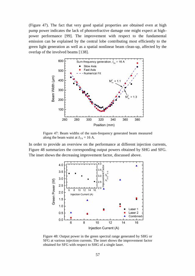
57
(Figure 47). The fact that very good spatial properties are obtained even at high
pump power indicates the lack of photorefractive damage one might expect at high-
power performance [99]. The improvement with respect to the fundamental
emission can be explained by the central lobe contributing most efficiently to the
green light generation as well as a spatial nonlinear beam clean-up, affected by the
overlap of the involved beams [138].
Figure 47: Beam widths of the sum-frequency generated beam measured
along the beam waist at ITA = 16 A.
In order to provide an overview on the performance at different injection currents,
Figure 48 summarizes the corresponding output powers obtained by SHG and SFG.
The inset shows the decreasing improvement factor, discussed above.
Figure 48: Output power in the green spectral range generated by SHG or
SFG at various injection currents. The inset shows the improvement factor
obtained for SFG with respect to SHG of a single laser.

58
The results show that the concept of SFG with spectrally combined diode lasers
helps to efficiently enhance the output power of diffraction-limited visible diode
laser systems. Based on their wavelength tunability these systems provide an
additional spectral flexibility which is not achieved with laser systems limited to
certain emission wavelengths. In order to increase the output power even further the
concept can be expanded, for example, by combining multiple lasers with additional
gratings or multiplexed VBGs [128],[139].

59
6. Extending the concept of spectrally combined diode lasers
It has been shown that beam combining with subsequent frequency conversion can
be used to efficiently enhance the amount of visible laser emission. The question
remains how to further increase the output power of visible diode laser systems in a
compact and efficient manner. One key advantage of diode lasers is their wavelength
tunability. This enables active adjustments of emission wavelengths in order to
obtain phase-matching for nonlinear frequency conversion. In the above concept this
principle is utilized to achieve sum-frequency generation at various crystal
temperatures. The same principle can also be applied in an advanced approach
involving multiple lasers. For example, in addition to SFG of two combined lasers,
additional lasers can be added for simultaneous nonlinear interactions at the same
crystal temperature. The generated emission will benefit from all contributions. In
addition, the ability of wavelength tuning potentially enables single spectral mode
emission. However, this new concept requires spectral beam combining of multiple
laser. Using additional gratings increases the number of optical components and size
of such setups. A more compact approach is to use multiplexed volume Bragg
gratings [139]. This chapter summarizes the results obtained with frequency
conversion of three diode lasers, spectrally combined in a multiplexed VBG [140].
6.1. Phase-matching for simultaneous SHG and SFG
The indicated concept of simultaneous nonlinear interactions at fixed crystal
temperatures leaves the question about potential limitations. Regarding beam
combining the total number of lasers is mainly limited by the custom design of the
applied multiplexed grating. Each laser diffracted by the grating has to fulfill the
Bragg condition. In a multiplexed grating the first combination of two lasers pre-
determines the emission wavelengths and angles of incidence for any additional
diffracted laser. The emission wavelength of a transmitted laser is still tunable for
efficient frequency conversion. For example, in a scenario of three combined lasers
one diffracted laser serves as a pump laser for frequency doubling. Obtaining the
same emission wavelength by SFG of the other two lasers implies that their
wavelengths are selected accordingly, using the simple relation
(57)
Here λ1 and λ3 represent the fundamental wavelengths for sum-frequency generation
required for obtaining the same emission wavelength as in case of SHG (λSHG). The
limiting factor regarding possible wavelength combinations at fixed crystal
temperatures is phase-matching. Figure 49 shows the spectral tolerance for SFG at
fixed conditions. The simulation is based on the equations (35) and (37) for a
lithium niobate crystal as applied in chapter 5. The crystal temperature is set to

60
37 °C for phase-matched SHG at 1062.4 nm. The shown curve is obtained by
changing the fundamental wavelengths for SFG in accordance with equation (57).
Figure 49: Simulated wavelength tolerance for quasi phase-matched SFG
using a 30 mm long 5% MgO-PPLN crystal. The simulation is based on
fixed crystal parameters and the fundamental wavelengths (1, 3) are
selected with respect to the desired emission wavelength of 531.2 nm.
At 50% of maximum intensity the spectral range for additional wavelength
combinations at a constant crystal temperature is 23.6 nm. At 95% of maximum
intensity the available wavelength span is still 12.3 nm. By engineering a
multiplexed VBG with low spectral acceptance, many wavelength tunable lasers
with narrow laser emission can be combined within this wavelength span. The
requirements of this concept perfectly match with the unique key advantages of
diode lasers, making it an ideal approach for power scaling of visible diode laser
systems.
6.2. Theoretical description for simultaneous SHG and SFG
Assuming that the wavelengths of three beam combined lasers (1 > 2 > 3) are
selected in a manner that phase-matching is exclusively provided for SFG of 1, and
3 and SHG of 2, the scenario of simultaneous SHG and SFG is described by a total
of five induced nonlinear polarizations and five electric fields. It should be noted
that back coupling between these two processes is neglected in order to simplify the
theoretical description. Under the assumption of phase-matching (kSHG = kSFG),
single-mode emission (SHG = SFG), and zero phase delay between the second
harmonic and the sum-frequency fields (SHG = SFG), solving the nonlinear wave
equation results in the coupled amplitude equation for the generated emission

61
(
) (58)
Here the indices 1, 2, and 3 refer to the fundamental waves. It becomes obvious that
under the above assumptions, the amplitude of the generated emission is given by
the sum of the individual interactions. This also applies in case of multiple
simultaneous interactions. A more detailed analysis is provided in the appendix.
The corresponding intensity is obtained by integration over the entire crystal length,
which results in the following relation
(
) (
)
(
) (
)
(
√
√ ) (
)
(59)
The equation reveals the individual contributions of SHG and SFG. A third term
indicates a coupling between the two nonlinear interactions. Under the above
assumptions this term represents the contribution from occurring interference effects
that do not alter the total intensity, see below.
6.3. Setup for simultaneous nonlinear interactions
Figure 50: Setup for spectral beam combining of three lasers in a
multiplexed VBG with subsequent frequency conversion.

62
The experimental setup for spectral beam combining in Figure 50 is similar to the
setups applied above. It consists of three individual DBR-tapered diode lasers
collimated and corrected for astigmatism. All lasers are positioned at roughly the
same distance to a multiplexed volume Bragg grating. The VBG is 3.99 mm thick
with a 10 mm x 10 mm aperture. It is designed for beam combining of three lasers
and therefore contains two grating structures. The individual gratings have an
average diffraction efficiency of DE > 99% and spectral acceptance bandwidths of
0.26 nm and 0.28 nm, respectively. One grating is designed for diffraction at
1062.5 nm and Bragg angles of 11.1° and 1.0° with respect to the surface normal.
The second grating is designed for diffraction at 1062.0 nm wavelengths at 1.2° and
-9.0°. Beam combining of three lasers is obtained by adjusting the emission
wavelengths and angles of incidence until the diffracted beams overlap properly
with the transmitted beam. The left part of the setup shows the optical isolation and
frequency conversion analog to the setup discussed in section 5.2.
6.4. Spectral beam combining in a multiplexed grating
All three DBR-tapered diode lasers are operated at IRW = 300 mA and ITA = 4 A. The
transmitting Laser 1 is operated at a laser temperature of 20 °C, which results in an
emission wavelength of 1062.78 nm (Figure 51). In order to obtain spectral beam
combining of Laser 1 and 3, the angle of incidence and the emission wavelength of
Laser 3 are adjusted accordingly. The corresponding wavelength is 1062.05 nm at a
laser temperature of 13 °C. Once these two lasers are combined, the position of the
VBG should not be changed. This fixed position of the grating pre-defines the
required wavelengths and angles of incidence for any additional laser. Spectral beam
combining with Laser 2 is obtained at a laser temperature of 26.4 °C and an
emission wavelength of 1063.19 nm. All three lasers provide narrow emission
bandwidths with FWHM 9 pm. The measured side-lobes are suppressed by 10 dB
and may be caused by unexpected optical feedback requiring further investigations.
The overlap between the three lasers is controlled by observing the beam waist
profiles (Figure 52) and an image of the collimated, combined beam at a longer
distance (Figure 53). Both figures indicate a good overlap of the individual lasers.
The total power measured for the individual lasers adds up to 3.78 W. After beam
combining an output power of 3.39 W is measured. This results in a combining
efficiency of 90%. The corresponding M24 values of the combined beam are 1.9 in
the slow axis and 1.5 in the fast axis (Figure 54).

63
Figure 51: Resulting spectrum of three beam combined lasers, revealing
the individual contributions.
Figure 52: Normalized beam waist intensity profiles of three overlapping
DBR-tapered diode lasers in both transverse directions.

64
Figure 53: Image of the collimated, combined beam at a longer distance.
Figure 54: Beam widths of the combined beam measured along the beam
waist at IRW = 300 A and ITA = 4 A.
6.5. Frequency conversion of three combined lasers
For simultaneous nonlinear interactions frequency doubling of Laser 2 is used as a
reference. The required crystal temperature is 44.7 °C, resulting in a maximum
second harmonic output power of 40 mW at 531.59 nm. The available pump power
and the corresponding optical conversion efficiency are 1.03 W and 4%,
respectively. Without changing the crystal position or its temperature, Laser 1 is
wavelength tuned in order to obtain efficient sum-frequency generation of Laser 1
and Laser 3. The resulting laser temperature of 39.1 °C reduces the available pump

65
power to 0.63 W. The output power available for SFG adds up to a total of 1.76 W
and results in 100 mW of green light (6%). The output power for simultaneous
interactions is given by the sum of the individual nonlinear contributions and results
in a total of 140 mW (5%). A second option for simultaneous interactions would
have been SFG with Laser 2 and Laser 3, and SHG with Laser 1. However, this
scenario was not carried out in this work
In order to obtain similar wavelengths from the two nonlinear processes, the spectral
emission of Laser 1 is fine-tuned accordingly. Figure 55 shows the spectrum of
green laser emission generated by simultaneous nonlinear interactions. The spectrum
is located at the desired wavelength and has a spectral bandwidth < 5 pm indicating
a good match between the obtained emission wavelengths. The side-lobes in Figure
55 are also observed in the near-infrared (Figure 51) and may be caused by
unexpected optical feedback.
Figure 55: Emission spectrum of simultaneous SHG and SFG. At a fixed
crystal temperature the wavelength of Laser 1 is adjusted in order to
obtain matching emission wavelength for SHG and SFG.
Analyzing the green emission at matching wavelengths with a photodiode and an
oscilloscope reveals the above mentioned interference effects resulting from the
superposition of coherent waves [141]. Due to these effects the combined signal is
given by the sum of the individual contributions but shows additional random
modulations that are not seen in case of separate SHG and SFG (Figure 56). The
random nature of this behavior may result from wavelength fluctuations of the diode
lasers. The detected modulations disappear by detuning the temperature of Laser 1,
which indicates the requirement of matching green emission wavelengths in order to
observe these effects.

66
Figure 56: Direct comparison of the measured photodiode signal at
individual and simultaneous SHG and SFG. The measurement reveals the
onset of interference effects caused by the superposition of coherent
waves.
The spatial quality of the combined green beam shows values of M24 = 2.3 in the
slow axis and M2
4 = 1.6 in the fast axis (Figure 57). The measured values are
comparable to the fundamental laser emission but indicate the lack of spatial
filtering as observed in Section 5.3. In order to improve the spatial quality of
simultaneous nonlinear interactions the overlap of the involved beams needs to be
improved even further.
Figure 57: Beam widths of the simultaneously generated green emission
measured along the beam waist.
Frequency conversion of three beam combined lasers enables a total of six nonlinear
interactions. Figure 58 shows the generated output power as a function of crystal

67
temperature. Due to the different emission wavelengths of the three lasers separated
by 1 nm, the individual nonlinear contributions can be clearly distinguished by their
phase-matching temperature. The only exception is the central maximum that is
based on simultaneously phase-matched frequency doubling and sum-frequency
generation. The difference in output power for comparable nonlinear interactions
results from variations in fundamental pump power due to increased laser
temperatures, the overlap of the individual lasers, and the crystal position being
optimized for SHG of Laser 2 and SFG of Laser 1 and Laser 3.
Figure 58: Output power as a function of crystal temperature in case of
nonlinear frequency conversion with three combined fundamental lasers.
Each maximum represents phase-matching for the corresponding
nonlinear interaction. The central maximum consists of contributions from
simultaneous SHG and SFG.
The results indicate that spectral beam combining with subsequent nonlinear
frequency conversion can be expanded using multiple lasers and a multiplexed
VBG. The total number of lasers to be combined in a single grating is limited by its
design parameters. The number of simultaneous frequency conversions with
multiple lasers is limited by the spectral acceptance bandwidth of the nonlinear
crystal. It is shown that the output power in such systems is determined by the sum
of the individual contributions, indicating the great potential towards power scaling
in advanced diode laser systems.

68

69
7. Diode laser based pumping of titanium sapphire lasers
Regarding biomedical applications of green diode laser systems, the main focus in
this work is on direct pumping of Ti:sapphire lasers for optical coherence
tomography (OCT). In most cases green emission is provided by frequency
converted solid state lasers, which can have low wall-plug efficiencies and
significantly add to the dimensions and price of Ti:sapphire laser systems. Obtaining
the required high-power green light emission directly with simple and more efficient
diode lasers is challenging. Applying nonlinear frequency conversion can overcome
these limitations. This chapter summarizes the results obtained by direct pumping of
Ti:sapphire lasers with a frequency doubled diode laser [142].
7.1. Direct pumping of Ti:sapphire lasers
Ti:sapphire lasers belong to the group of transition-metal-ion lasers characterized by
a tunability over a wide spectral range of several hundred nanometers [2],[143]. In
case of titanium doped sapphire laser crystals the laser emission ranges between
600 nm - 1100 nm [144]. In mode-locked operation Ti:sapphire lasers provide
ultrashort femtosecond pulses [145] that are required in many biomedical imaging
applications such as two-photon microscopy, coherent anti-Stokes Raman scattering
microscopy or optical coherence tomography [33],[34],[35].
Ti:sapphire lasers are characterized by a maximum absorption around 500 nm [143]
and high pump thresholds. Therefore, pump lasers should ideally provide more than
1 W (CW) of green light with good spatial quality and high efficiencies without
adding to the size of the Ti:sapphire systems. Direct pumping of Ti:sapphire lasers
has been demonstrated with laser systems such as argon-ion lasers, neodymium
based solid state lasers, thin disk lasers or fiber lasers [143],[146],[147],[148],[149].
A more efficient approach towards green laser emission is the use of direct green
light emitting lasers. Green emitting diode lasers were shown with output powers up
to 1 W limited by the laser crystal qualities or spatial qualities [150],[151]. With
diode pumped Pr3+
-doped laser crystals more than 700 mW were obtained at 523 nm
[152].
A solution towards increased output powers of several watts is frequency conversion
of optically pumped infrared lasers [85],[109],[153]. Direct pumping of Ti:sapphire
lasers with a 5 W frequency doubled optically pumped semiconductor laser resulted
in an output power of 0.5 W at pulsewidths < 20 fs [154]. A major disadvantage of
such configurations is that two conversion processes are required to generate green
light, which negatively affects the overall wall-plug efficiencies.
These drawbacks are overcome by more efficient blue diode lasers or frequency
converted diode lasers that may also lead towards low-cost Ti:sapphire lasers with
small footprints. In addition, the short upper-state lifetimes of diode lasers in
comparison to ≈ 3 µs for Ti:sapphire laser crystals [137],[144] reduce the risk of
transferring intensity noise caused by relaxation oscillations to the output of the

70
Ti:sapphire laser. Different groups examined the potential of blue gallium nitride
based pump lasers with output powers of P ≈ 1 W. Direct pumping at 450 nm
resulted in Ti:sapphire laser emission of 13 mW at pulsewidths of 114 fs [155]. Up
to 101 mW and pulsewidths of 15 fs were obtained with double-sided pumping
[156],[157]. Unfortunately, pumping at such short wavelengths introduced
additional losses within the laser crystal that significantly reduced the conversion
efficiencies and were not observed at green pump wavelengths [155].
This leaves the option of frequency converted diode lasers. As shown above, DBR-
tapered diode lasers fulfill all requirements for efficient green light generation
[32],[103], and frequency conversion results in high-power emission with good
spatial quality. Based on previous results obtained with a single emitter, a portable
and robust green diode laser system is developed for direct pumping of Ti:sapphire
lasers.
7.2. Experimental setup for a diode based pump laser
The setup illustrated in Figure 59 is a more compact version of the approach
published by Jensen et al. [32]. A 1062 nm DBR-tapered diode laser is collimated in
both axes, corrected for astigmatism, and protected against optical feedback. The
diode laser is connected to an electronic filter that suppresses electronic noise from
the high-power switch-mode power supply and therefore prevents a noise transfer
when pumping a Ti:sapphire laser. In order to reduce the footprint of the setup, two
mirrors tilt the beam over 180°. A lens with a focal length of f = 100 mm generates a
beam waist of approximately 60 μm inside the 5% MgO:LiNbO3 crystal. A dichroic
mirror separates the second harmonic from the fundamental laser emission. An
additional lens with a focal length of f = 200 mm collimates the green light to an
approximately 2.5 mm wide beam for further experiments.
Figure 59: Experimental setup for compact diode laser based single-pass
frequency conversion.

71
7.3. Characterization of the diode based pump laser
The RW and TA of the diode laser are operated at injection currents of 300 mA and
14 A, respectively. The maximum fundamental pump power available for frequency
conversion is 8.8 W. Second harmonic generation at a crystal temperature of 37 °C
results in a maximum of 1.28 W of green light (Figure 60). The maximum
conversion efficiency is 14.5%. The corresponding nonlinear and wall-plug
efficiencies are 1.9 %/W and 4%, respectively.
Figure 60: Second harmonic power and conversion efficiency versus
pump power of the frequency converted diode laser.
Figure 61: Spectrum of the second harmonic at maximum performance.
The inset shows the fundamental emission spectrum.
Optimum phase-matching is obtained at a laser temperature of 17.66 °C. This results
in fundamental and second harmonic emission wavelengths of 1062.45 nm and
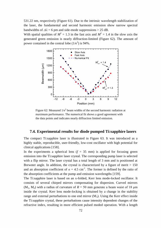
72
531.22 nm, respectively (Figure 61). Due to the intrinsic wavelength stabilization of
the laser, the fundamental and second harmonic emission show narrow spectral
bandwidths of = 6 pm and side-mode suppressions > 25 dB.
With spatial qualities of M2 = 1.3 in the fast axis and M
2 = 1.4 in the slow axis the
generated green emission is nearly diffraction-limited (Figure 62). The amount of
power contained in the central lobe (1/e2) is 94%.
Figure 62: Measured 1/e2 beam widths of the second harmonic radiation at
maximum performance. The numerical fit shows a good agreement with
the data points and indicates nearly diffraction limited emission.
7.4. Experimental results for diode pumped Ti:sapphire lasers
The compact Ti:sapphire laser is illustrated in Figure 63. It was introduced as a
highly stable, reproducible, user-friendly, low-cost oscillator with high potential for
clinical applications [158].
In the experiments a spherical lens (f = 35 mm) is applied for focusing green
emission into the Ti:sapphire laser crystal. The corresponding pump laser is selected
with a flip mirror. The laser crystal has a total length of 3 mm and is positioned at
Brewster angle. In addition, the crystal is characterized by a figure of merit > 150
and an absorption coefficient of α = 4.5 cm-1
. The former is defined by the ratio of
the absorption coefficients at the pump and emission wavelengths [159].
The Ti:sapphire laser is based on an x-folded, Kerr lens mode-locked oscillator. It
consists of several chirped mirrors compensating for dispersion. Curved mirrors
(M1, M2) with a radius of curvature of R = 50 mm generate a beam waist of 18 μm
inside the crystal. Kerr lens mode-locking is obtained by a change in the stability
range and external perturbations to one end mirror (M3). Using the Kerr effect inside
the Ti:sapphire crystal, these perturbations cause intensity dependent changes of the
refractive index, resulting in more efficient pulsed moded operation. With a length

73
of about 1.75 m and νRep = c/2L [53], the repetition rate νRep of this oscillator exceeds
80 MHz. The second end mirror (M4) is used as an output coupler with 3%
transmission for additional measurements.
Figure 63: Illustration of the Ti:sapphire oscillator used in the
experiments. The two arms of the 1.75 m long oscillator are shown with
dashed and dotted lines. A flip mirror is used to select a laser system for
direct pumping.
The commercial pump laser used for comparison is a diode pumped solid state
(DPSS) laser (Laser Quantum, Excel Laser). It provides a diffraction limited beam
(M2 < 1.1) with a beam diameter of 1.8 mm and a maximum power of 1.5 W at
532 nm. Its wall-plug efficiency is below 2%.
When pumping the Ti:sapphire laser with the commercial system, a maximum
power of 180 mW is obtained (Figure 64). The corresponding conversion efficiency
from green to near-infrared is 12%. Direct pumping with 1.1 W from the diode laser
leads to an emission of 105 mW. The optical conversion efficiency is reduced to
9.5%. Exchanging the collimation lens (f = 160 mm) in order to reduce the beam
width of the diode laser down to 2 mm, has a negligible effect and results in a
maximum of 110 mW at 1.2 W of green light (9.2%). Compared to the commercial
pump laser similar noise properties are measured.
The direct comparison shows that direct pumping with the commercial DPSS laser
exceeds the performance achieved with the diode laser by 20 mW to 30 mW at
similar pump powers. This deviation corresponds to a 25% drop in optical
conversion efficiency for a diode pumped Ti:sapphire laser. The estimated pump
threshold increases from 0.2 W to 0.33 W. The slope efficiency decreases from
13.8% to 12.7%. The advantage of diode pumped Ti:sapphire lasers becomes
obvious when comparing the wall-plug efficiencies. Due to the superior efficiency
of the diode laser the wall-plug efficiency of the Ti:sapphire laser is still improved
by a factor > 2.

74
Figure 64: Obtained output power of the direct pumped Ti:sapphire laser
operated in CW mode. Lens 1: f = 200 mm. Lens 2: f = 160 mm.
The deviation observed for CW Ti:sapphire lasers is also seen in mode-locked
operation (Figure 65). With the diode laser, a maximum of 82 mW is obtained at
1.2 W of pump power (6.8%). The maximum efficiency of 7.1% is measured at a
larger beam width, generating 78 mW. Applying the commercial pump laser,
86 mW are achieved at 1 W of pump power (8.6%).
Figure 65: Obtained output power of the direct pumped, mode-locked
Ti:sapphire laser (f1 = 200 mm, f2 = 160 mm).
One explanation for reduced optical conversion efficiencies obtained with the diode
laser can be the reduced spatial quality negatively affecting the overlap of the pump
beam and generated emission within the Ti:sapphire crystal. In addition, no changes
were made to the oscillator when switching from a commercial to a diode based

75
pump laser. An optimization with respect to the diode laser could reduce or
eliminate the observed deviations.
Figure 66: Emission spectra of a mode-locked Ti:sapphire laser directly
pumped with a diode laser or DPSS laser.
Figure 67: Interferometric autocorrelation trace of the diode pumped
Ti:sapphire laser. The inset shows the corresponding spectrum of the
mode-locked laser.
In order to estimate the performance of the mode-locked Ti:sapphire laser, emission
spectra and interferometric autocorrelation traces are measured. Both pump lasers
are set to 1.2 W of pump power. This results in a Ti:sapphire laser emission of
52 mW with the diode laser and 60 mW with the commercial system. The reduced
performance compared to the results shown above is due to changes made for the
oscillator in order to achieve maximum bandwidths. The emission spectra obtained
in mode-locked operation show spectral widths of ΔλFWHM = 112 nm for the diode

76
laser and ΔλFWHM = 115 nm for the commercial laser, respectively (Figure 66). The
spectral widths measured according to the 1/e2 criteria are 158 nm and correspond to
bandwidths of 78 THz. The distinct side-lobes at 700 nm of the measured spectra are
caused by a sharp phase change induced by the chirped mirrors.
The interferometric autocorrelation trace for the diode pumped Ti:sapphire laser is
shown in Figure 67. From this trace a pulse width of less than 20 fs is estimated. The
trace shows slightly imperfect alignment and dispersion management. This is
indicated by the unusual behavior in the wings of the trace and a reduced signal-to-
noise ratio of 7.65:1 compared to the ideal ratio of 8:1 [160]. Due to the non-
Gaussian spectral profile the generated pulses are not transform limited, which
would result in minimum pulse widths [161].
It is demonstrated that frequency doubled diode lasers are suitable for direct
pumping of ultrashort pulsed Ti:sapphire lasers. Compared to a commercial pump
laser, similar noise properties are measured. The reduced power performance with
the diode laser can be compensated by a superior wall-plug efficiency. Further
optimization of the oscillator with respect to the diode laser may help to improve the
pump conversion efficiency. In addition, smaller footprints of diode based pump
lasers will enable more efficient, low-cost Ti:sapphire lasers with reduced
dimensions.

77
8. Diode pumped Ti:sapphire lasers for OCT
Despite the promising results achieved with direct pumping of Ti:sapphire lasers, the
question remains how diode pumped Ti:sapphire lasers perform in biomedical
applications such as optical coherence tomography (OCT). This chapter summarizes
the results obtained with a diode based system applied to the skin and retina [162].
8.1. Optical coherence tomography
OCT is a well-established, non-invasive, in vivo imaging technique in order to
obtain 3D images of the morphology of biological tissues [163]. It allows for
applications such as early detection of retinal pathologies, guiding of surgical and
microsurgical procedures, and optical biopsy often in conjunction with screening of
early malignancies [164].
The underlying principle is interferometric imaging of a scattering sample. Light of
a low coherent source is split up into a reference arm and a sample arm of an
interferometer. In time-domain OCT, depth resolved images are obtained by
monitoring the interference intensity while continuously changing the longitudinal
path length of the reference arm [164]. Once the path differences between the two
arms are within the coherence length of the source a cross-correlated signal is
measured and can be translated into depth information. Such a single local
measurement is called an A-scan. Lateral scanning across the sample enables the
reconstruction of cross-sectional images, which can be stacked to obtain a three
dimensional view.
In frequency-domain OCT, the reference arm is fixed and depth resolved images can
be obtained by evaluating the measured interference pattern with a spectrometer.
The Fourier transform of the measured spectrum provides depth-resolved reflectivity
profiles [164]. The measurable penetration depth is given by the ability of the
detector to measure high frequencies. Without a required movement of optical
components, this method is faster and more stable than time-domain imaging.
Furthermore, measuring individual spectral components rather than the entire
interference signal increases the sensitivity [165].
The transverse resolution of an OCT system is determined by the ability to focus the
incident beam. The axial resolution l is given by the following relation [164]
(60)
According to this equation the axial resolution mainly depends on the center
wavelength 0 and the bandwidth of the applied light source. Typical sources are
broadband near-infrared lasers with center frequencies located within a range of
700 nm - 1300 nm. Compared to longer wavelengths or the visible spectral range,
this spectral region enables increased penetration depths because of 2 - 3 orders of

78
magnitude lower absorption by main tissue components such as water, hemoglobin,
and melanin [166]. Due to the wavelength dependent optical tissue properties
affecting the penetration depth, contrast, and axial resolution, the laser parameters
have to be properly chosen [167].
8.2. Diode based laser system for OCT measurements
Based on the concept shown in chapter 7, a compact green diode laser with a
footprint of 140 mm x 90 mm is developed for a potential integration into a
Ti:sapphire laser system. The laser is collimated using an aspheric lens with a focal
length of f = 2 mm (NA = 0.5) and a cylindrical lens with a focal length of f = 4 mm
(NA = 0.5). The combination of these two lenses generates a nearly circular beam
with roughly 1 mm in diameter. In order to prevent optical feedback the AR-coated
lenses are followed by a 30 dB optical isolator and a λ/2 waveplate. In between two
mirrors positioned at angles of 45° an achromat with a focal length of f = 40 mm
generates a beam waist of about 35 μm, which proved to be optimum in the
experiments.
Frequency conversion is carried out in a 30 mm long, 10° angle cut 5%
MgO:LiNbO3 crystal (HCPhotonics). Although angle cut crystals are especially
applied to suppress optical feedback, the optical isolator still has to be used to
protect the diode laser. The periodically poled crystal has a poling period of
6.92 µm.
Behind the crystal, the fundamental laser emission and the second harmonic are
separated with a dichroic mirror. An additional lens (f = 75 mm) collimates the
green laser radiation to an approximately 1 mm wide beam available for direct
pumping of Ti:sapphire laser oscillators.
Figure 68: Setup for active stabilization of the green diode laser system
using electronic feedback from a photodiode (PD).
In order to apply this diode laser in an OCT setup, it should ideally provide
sufficient output power (P > 1.3 W) with a power stability of ± 0.5%. In the
described setup the diode laser is stabilized by an external photodiode feedback loop
regulating the injection current to the RW of the laser (Figure 68). Figure 69 shows
the corresponding measurement over one hour. Due to the feedback loop the output
power of 1.45 W is kept stable within ± 3 mW (± 0.2%), which fulfills the
requirements given above.

79
Figure 69: Output power of the compact green diode laser system
measured over one hour. The inset shows an enhanced view of the
measured data points.
8.3. OCT imaging with a diode pumped Ti:sapphire laser
The diode pumped Ti:sapphire laser is based on an oscillator as previously
introduced in [158] and section 0. For retina measurements the oscillator is
integrated into a spectrometer based frequency-domain OCT system (Figure 70).
The OCT device is based on a solid state pumped Ti:sapphire laser system with a
light emitting diode fixation target (FIX) and a scanning laser ophthalmoscope
(SLO) for tracking eye-motion. The fiber based design of the OCT system enables
simultaneous integration of different light sources, as indicated here with a direct
diode pumped Ti:sapphire laser (DDPSSL) and a superluminescent diode (ASE).
Fiber-optic couplers split the emission into a shared patient interface and external
delay reference arms (REF). Each reference arm consists of a fiber coupled
collimator, an attenuator, and a reflector. This compensates differences in dispersion
caused by fiber length mismatches and the propagation in biological tissue. The
interference signals are evaluated using camera-based spectrometers. The
corresponding cameras are selected with respect to the applied wavelengths. Data
acquisition and processing are used for real time display of the obtained images. The
speed of the OCT system is given by depth sampling line rates of 70 kHz.

80
Figure 70: Experimental setup for a dual wavelength OCT system for
retina imaging. (Courtesy of A. Unterhuber, Med. Univ. Vienna)
Retina measurements are carried out with different light sources. The corresponding
source parameters are summarized in Table 3. For eye safety the output powers are
reduced below the safety limit. Figure 71 shows a direct comparison of the OCT
images obtained with different light sources at 800 nm and 880 nm.
The images show that the low absorption at 800 nm in an ocular medium is well
suited for obtaining information about the architectural morphology of the retina as
an indicator of pathological changes [168],[169]. It should be noted that the images
are averaged over 100 (a), 50 (b), and 20 frames (c). The difference in the number of
frames is based on the axial resolution with the individual sources. Averaging
images with high axial resolution allows for a low number of frames. Saturations
effects at larger numbers would reduce the image quality. On the other hand, low
resolution images can be averaged with multiple frames in order to improve the final
image. The direct comparison of the three sources reveals the difference in
resolution resulting from the applied emission bandwidths listed in Table 3. While
the image obtained with the superluminescent diode shows a poor axial resolution,
the difference becomes less obvious when comparing Ti:sapphire lasers with
moderate (b) or ultrabroad bandwidths (c).
Table 3: Spectral bandwidths and output power of different sources
applied in retina OCT measurements.
Light source Spectral bandwidth
FWHM / nm
Applied output power
P / mW
Diode pumped Ti:sapphire laser 90 @ 800 nm 0.8
Solid state pumped Ti:sapphire laser 170 @ 800 nm 0.8
Superluminescent diode 47 @ 880 nm 1.2
Superluminescent diode 111 @ 1070 nm 4.0

81
Figure 71: In vivo OCT image of the retina at center wavelengths of
800 nm and 880 nm. The images show the results obtained with a
superluminescent diode (a), a diode pumped Ti:sappire laser (b) and a
solid state pumped ultrabroad bandwidth Ti:sapphire laser system (c).
Applying sources around 800 nm helps to resolve intraretinal layers down to the
choroid. The main limiting factor regarding the penetration depth is the strong
scattering and absorption by melanin in the retinal pigment epithelium. In order to
penetrate deeper into the choroid longer wavelengths need to be applied. Figure 72
shows a direct comparison of images obtained with different light sources at
comparable bandwidths. It can be seen that the longer center wavelength of a
1070 nm superluminescent diode enables imaging below the retinal pigment
epithelium at the expense of axial resolution. Comparing the images obtained with
Ti:sapphire lasers shows that the image for the solid state pumped laser systems
seems to be more grainy, which may result from dispersion compensation artifacts
in the setup.

82
Figure 72: In vivo OCT image of the retina at center wavelengths of
800 nm and 1070 nm. The images show the results obtained with a
superluminescent diode (a), a diode pumped Ti:sappire laser (b) and a
solid state pumped Ti:sapphire laser system (c) at comparable bandwidths.
For skin measurements a similar OCT system is applied enabling a transversal
resolution of 12 µm over a scanned region of approximately 8 mm x 8 mm with
1024 sampling points per B-scan. The image acquisition rate is 47 kHz
(47000 A-scans/s). The source parameters applied in the measurements are
summarized in Table 4.
Table 4: Spectral bandwidths and spatial resolutions for light sources
applied in OCT skin measurements.
Light source Spectral bandwidth
FWHM / nm
axial resolution
l / µm
Diode pumped Ti:sapphire laser 30 @ 800 nm < 10
Diode pumped Ti:sapphire laser 90 @ 800 nm < 4
Solid state pumped Ti:sapphire laser 240 @ 800 nm < 3
Skin imaging is of high importance in order to diagnose morphological changes that
are potentially caused by malignant conditions and various skin diseases occurring
in epithelial tissues. [170],[171],[172]. Using OCT based imaging techniques, the
obtained imaging depth of about 1 mm - 2 mm is comparable to typical mechanical
biopsies. In comparison to this traditional method, optical biopsy allows for in situ,

83
real-time measurements with high resolution and has become a promising non-
invasive technique for imaging of micro-morphological details in tissue. Skin OCT
has been demonstrated in numerous applications such as tumor detection [173],
monitoring of wound healing processes and treatment effects [174],[175], and the
analysis of inflammatory skin conditions and burn depths [172],[176].
Figure 73 shows skin images obtained with all three Ti:sapphire laser systems. The
images are acquired at an output power of 2 mW. In all cases, the images visualize
the morphology of several cutaneous layers such as the epidermis and dermis, which
is of significant importance for early cancer detection [177]. In direct comparison to
the solid state pumped system the image quality at reduced spectral bandwidths is
sufficient and in principle allows measurements at reduced green pump power. In all
cases the achieved penetration depths are mainly limited by the emission
wavelength. Longer wavelength may be required in order to obtain greater depths at
the expense of axial resolution.
Figure 73: In vivo OCT image of human skin obtained with 800 nm
Ti:sapphire lasers. The upper two images show standard resolution OCT
with a diode pumped Ti:sapphire laser at different spectral bandwidths.
The bottom image shows ultrahigh resolution OCT with a solid state
pumped system.
The results obtained for retina and skin OCT clearly show the potential of diode
pumped Ti:sapphire laser systems for OCT measurements. In direct comparison
with solid state pumped systems a diode pumped laser provides similar results.
Increased pump thresholds for ultrabroad bandwidth Ti:sapphire lasers in high-
resolution OCT systems may be overcome by implementing high-power beam
combined green diode lasers, strengthening the application potential of diode lasers
in this biomedical field.

84

85
Conclusion
Diode lasers are increasingly attractive for numerous applications. In the biomedical
field the provided output power, spatial emission properties, and wavelength
coverage of diode lasers have been decisive aspects for their applications in
dermatology, diffuse spectroscopy and imaging, or fluorescence measurements. One
major challenge in diode laser technology is to obtain high-power laser emission at
wavelengths < 600 nm. Especially the green spectral range is of high importance for
dermatological applications or in direct pumping of ultrashort pulsed lasers in
conjunction with optical coherence tomography, two-photon microscopy or coherent
anti-Stokes Raman scattering microscopy.
Nonlinear frequency conversion of state-of-the-art near-infrared diode lasers
represents a necessary means to overcome these current limitations in diode laser
technology. Unfortunately, frequency doubling of a single emitter is limited by
thermal effects potentially resulting in laser degradation and failure. In this work
new concepts for power-scaling of green diode laser systems are introduced,
enhancing their application potential.
The underlying principle for power scaling is spectral beam combining. This
technique incoherently combines multiple lasers with an external optical component.
With two 1062 nm DBR-tapered diode lasers and a reflecting volume Bragg grating
more than 16 W of output power at combining efficiencies > 93% are obtained. In
comparison to lasers limited to specific atomic transitions the wavelength tunability
of diode lasers simplifies the process of obtaining an overlap of the combined
beams. Without affecting the spatial properties of the combined beams, spectral
beam combining of diode lasers has a high application potential in conjunction with
efficient, compact and cost-effective laser systems with increased brightness.
The condition of overlapping beams proves to be an ideal condition for subsequent
frequency conversion. Based on sum-frequency generation of two beam combined
diode lasers the amount of green light compared to single emitter frequency
doubling is increased by a factor of 2.5 - 3.2. At maximum performance 3.9 W are
achieved. It is also shown that nonlinear frequency conversion significantly
improves the spatial quality. Generating multiple watts of diffraction-limited green
light therefore increases the biomedical application potential of such diode laser
systems.
In order to increase the output power even further, the developed concept can be
expanded combining multiple diode lasers in a multiplexed grating. This is shown
for the example of three lasers incoherently combined in a compact and efficient
manner. In case of frequency conversion, the unique tunability of diode lasers allows
for matching emission wavelengths of simultaneous nonlinear interactions. The
obtained output power is given by the sum of the individual contributions and
indicates the potential for power scaling. The limiting factors in terms of extending
the concept are the grating properties and the acceptance bandwidths of nonlinear
crystals. Within these limits future setups can be based on an increased number of

86
simultaneous nonlinear frequency conversions, leading towards advanced, visible,
high-power diode laser systems.
In order to prove the application potential of green diode laser systems, a frequency
doubled DBR-tapered diode laser is applied for direct pumping of a mode-locked
Ti:sapphire laser. The resulting pump efficiencies are reduced to 75% of the values
achieved with a commercial green diode pumped solid state laser. However, due to a
superior wall-plug efficiency of the diode laser the overall efficiency of the
Ti:sapphire laser is improved by a factor of 2. In mode-locked operation, a spectral
bandwidth of 112 nm (FWHM) allows for sub-20 fs short pulses and proves the
competitive potential of diode lasers in conjunction with compact and efficient diode
pumped Ti:sapphire lasers.
Applying a diode pumped Ti:sapphire laser in OCT measurements of the retina and
skin shows similar results as obtained by solid state pumped systems. Implementing
the developed concept of beam combining based green diode laser systems will help
to overcome the high pump threshold for ultrabroad bandwidth Ti:sapphire lasers
required for high-resolution OCT, and strengthen the application potential of diode
lasers in this biomedical field.

87
References
[1] T. H. Maiman, Nature 187, 493-494 (1960).
[2] O. Svelto, S. Longhi, G. Della Valle, S. Kück, G. Huber, M. Pollnau, H.
Hillmer, S. Hansmann, R. Engelbrecht, H. Brand, J. Kaiser, A. B. Peterson,
R. Malz, S. Steinberg, G. Marowsky, U. Brinkmann, D. Lot, A. Borsutzky,
H. Wächter, M. W. Sigrist, E. Saldin, E. Schneidmiller, M. Yurkov, K.
Midorikawa, J. Hein, R. Sauerbrey, and J. Helmcke, Springer Handbook of
Lasers and Optics, F. Träger (ed.), Springer, New York (2007).
[3] A. Knigge, G. Erbert, J. Jonsson, W. Pittroff, R. Staske, B. Sumpf, M.
Weyers, and G. Tränkle, Electron. Lett. 41, 250-251 (2005).
[4] M. Kanskar, T. Earles, T. Goodnough, E. Stiers, D. Botez, and L. Mawst,
Electron. Lett. 41, 245-247 (2005).
[5] R. C. Youngquist, S. Carr, and D. E. N. Davies, Opt. Lett. 12, 158-160
(1987).
[6] K. W. Berndt, I. Gryczynski, and J. R. Lakowicz, Rev. Sci. Instrum. 61,
1816-1820 (1990).
[7] L. V. Wang and H. Wu, Biomedical Imaging: Principles and Imaging, Wiley,
New Jersey (2007).
[8] T. Kleine-Ostmann, P. Knobloch, M. Koch, S. Hoffmann, M. Breede, M.
Hofmann, G. Hein, K. Pierz, M. Sperling, and K. Donhuijsen, Electron. Lett.
37, 1461-1463 (2001).
[9] F. F. M. de Mul, J. van Spijker, D. van der Plas, J. Greve, J. G. Aarnoudse,
and T. M. Smits, Appl. Opt. 23, 2970-2973 (1984).
[10] C. A. Puliafito, T. F. Deutsch, J. Boll, K. To, Arch. Ophthalmol. 105, 424-
427 (1987).
[11] T. J. Dougherty, Sem. Surg. Oncol. 5, 6-16 (1989).
[12] L. Longo, S. Evangelista, G. Tinacci, and A. G. Sesti, Las. Surg. Med. 7,
444-447 (1987).
[13] A. Müller, S. Marschall, O. B. Jensen, J. Fricke, H. Wenzel, B. Sumpf, and P.
E. Andersen, „Diode laser based light sources for biomedical applications,“
Laser Phot. Rev. 7, 605-627 (2013).
[14] H. Wenzel, F. Bugge, M. Dallmer, F. Dittmar, J. Fricke, K.-H. Hasler, and G.
Erbert, IEEE Photon. Technol. Lett. 20, 214-216 (2008).
[15] K.-H. Hasler, B. Sumpf, P. Adamiec, F. Bugge, J. Fricke, P. Ressel, H.
Wenzel, G. Erbert and G. Tränkle, IEEE Photon. Technol. Lett. 20, 1648-
1650 (2008).
[16] K. Paschke, S. Einfeldt, A. Ginolas, K. Häusler, P. Ressel, B. Sumpf, H.
Wenzel, and G. Erbert, Conference on Lasers and Electro-Optics (CLEO),
CMN4 (2008).

88
[17] W. Pittroff, G. Erbert, B. Eppich, C. Fiebig, K. Vogel, and G. Tränkle, IEEE
Trans. Compon. Packag. Technol. 33, 206-214 (2010).
[18] L. Goldberg, H. F. Taylor, J. F. Weller, and D. R. Scifres, Appl. Phys. Lett.
46, 236-238 (1985).
[19] D. J. Derickson, R. J. Helkey, A. Mar, J. R. Karin, J. G. Wasserbauer, and J.
E. Bowers, IEEE J. Quantum Electron. 28, 2186-2202 (1992).
[20] C. Lin, P. L. Liu, T. C. Darnell, D. J. Eilenberger, and R. L. Hartman.
Electron. Lett. 16, 600-602 (1980).
[21] P. Unger, High Power Diode Lasers - Fundamentals, Technology,
Applications, with contributions by numerous experts, R. Diehl (ed.),
Springer, Berlin (2000).
[22] W. J. Alford, T. D. Raymond, and A. A. Allerman, J. Opt. Soc. Am. B 19,
663-666 (2002).
[23] M. Behringer, High Power Diode Lasers: Technology and Applications, F.
Bachmann, P. Loosen, and R. Poprawe (eds.), Springer, Berlin (2007).
[24] G. V. Agrawal and N. K. Dutta, Semiconductor Lasers 2nd
Edition, Van
Nostrand Reinhold, New York (1993).
[25] M. W. Fleming and A. Mooradian, IEEE J. Quantum Electron. 17, 44-59
(1981).
[26] K. C. Harvey and C. J. Myatt, Opt. Lett. 16, 910-912 (1991).
[27] R. W. Boyd, Nonlinear Optics 2nd Edition, Academic Press, San Diego
(2003).
[28] H. Taniguchi, H. Ishii, R. Minato, Y. Ohki, T. Namegaya, and A. Kasukawa,
IEEE J. Sel. Top. Quant. Electron. 13, 1176-1179 (2007).
[29] B. Sumpf, M. Zorn, M. Maiwald, R. Staske, J. Fricke, P. Ressel, G. Erbert,
M. Weyers, and G. Tränkle, Phot. Technol. Lett. 20, 575-577 (2008).
[30] Nichia product list (2012). Available at:
http://www.nichia.co.jp/en/product/laser.html (Accessed: 20 November
2012).
[31] B. Sumpf, K.-H. Hasler, P. Adamiec, F. Bugge, F. Dittmar, J. Fricke, H.
Wenzel, M. Zorn, G. Erbert, and G. Tränkle, IEEE J. Sel. Top. Quantum
Electron. 15, 1009-1020 (2009).
[32] O. B. Jensen, P. E. Andersen, B. Sumpf, K.-H. Hasler, G. Erbert, and P. M.
Petersen, Opt. Express 17, 6532-6539 (2009).
[33] W. Denk, J. H. Strickler, and W. W. Webb, Science 248, 73-76 (1990).
[34] P. D. Maker and R. W. Terhune, Phys. Rev. 137, A801-A818 (1965).
[35] D. Huang, E. A. Swanson, C. P. Lin, J. S. Schuman, W. G. Stinson, W.
Chang, M. R. Hee, T. Flotte, K. Gregory, C. A. Puliafito, and J. G. Fujimoto,
Science 254, 1178-1181 (1991).
[36] M.-W. Hsiung, B.-H. Kang, W.-F. Su, L. Pai, and H.-W. Wang, Ann. Otol.
Rhinol. Laryngol. 112, 534-539 (2003).

89
[37] Y. Kishimoto, S. Hirano, N. Kato, A. Suehiro, S.-I. Kanemaru, and J. Ito,
Ann. Otol. Rhinol. Laryngol. 117, 881-885 (2008).
[38] H. Miyazaki, J. Kato, H. Watanabe, H. Harada, H. Kakizaki, A. Tetsumura,
A. Sato, and K. Omura, Oral Surg. Oral Med. Oral Pathol. Oral Radiol.
Endod. 107, 164-172 (2009).
[39] A. Knauer, G. Erbert, R. Staske, B. Sumpf, H. Wenzel, and M. Weyers,
Semicond. Sci. Technol. 20, 621-624 (2005).
[40] B. Sumpf, K.-H. Hasler, P. Adamiec, F. Bugge, J. Fricke, P. Ressel, H.
Wenzel, G. Erbert, and G. Tränkle, Proc SPIE 7230, 72301E (2009).
[41] M. Manasevit, Appl. Phys. Lett. 12, 156-158 (1968).
[42] A. Y. Cho, J. R. Arthur, Jr., Prog. Solid State Chem. 10, 157-192 (1975).
[43] P. Crump, G. Blume, K. Paschke, R. Staske, A. Pietrzak, U. Zeimer, S.
Einfeldt, A. Ginolas, F. Bugge, K. Häusler, P. Ressel, H. Wenzel, and G.
Erbert, Proc. SPIE 7198, 719814 (2009).
[44] K.-J. Boller, B. Beier, and R. Wallenstein, High Power Diode Lasers -
Fundamentals, Technology, Applications with contributions by numerous
experts, R. Diehl (ed.), Springer, Berlin (2000).
[45] E. S. Kintzer, J. N. Walpole, S. R. Chinn, C. A. Wang, and L. J. Missaggia,
IEEE Phot. Technol. Lett. 5, 605-608 (1993).
[46] W. Both and J. Piprek, J. Therm. Anal. 36, 1441-1456 (1990).
[47] G. Erbert, A. Bärwolff, J. Sebastian, and J. Tomm, High Power Diode Lasers
- Fundamentals, Technology, Applications with contributions by numerous
experts, R. Diehl (ed.), Springer, Berlin (2000).
[48] B. Sumpf, M. Maiwald, A. Müller, A. Ginolas, K. Häusler, G. Erbert, and G.
Tränkle, IEEE Compon. Packag. Manuf. Technol. 2, 116-121 (2012).
[49] M. Maiwald, A. Ginolas, A. Müller, A. Sahm, B. Sumpf, G. Erbert, and G.
Tränkle, IEEE Phot. Technol. Lett. 20, 1627-1629 (2008).
[50] M. G. Littman and H. J. Metcalf, Appl. Opt. 17, 2224-2227 (1978).
[51] K. Liu and M. G. Littman, Opt. Lett. 6, 117-118 (1981).
[52] H. Kogelnik and C. V. Shank, Appl. Phys. Lett. 18, 152-154 (1971).
[53] B. E. A. Saleh and M. C. Teich, Fundamentals of Photonics, J. W. Goodman
(Ed.), Wiley Interscience, New York (1991).
[54] S. Wang, IEEE J. Quantum Electron. QE-10, 413-427 (1974).
[55] J. Fricke, H. Wenzel, M. Matalla, A. Klehr, and G. Erbert, Semicond. Sci.
Technol. 20, 1149-1152 (2005).
[56] J. Fricke, W. John, A. Klehr, P. Ressel, L. Weixelbaum, H. Wenzel, and G.
Erbert, Semicond. Sci. Technol. 27, 055009 (2012).
[57] J. N. Walpole, Opt. Quantum Electron. 28, 623-645 (1996).
[58] A. E. Siegman, DPSS (Diode Pumped Solid State) Lasers: Applications and
Issues, M. Dowley (Ed.), Vol. 17 of OSA Trends in Optics and Photonics
(Optical Society of America, 1998), paper MQ1.

90
[59] P. A. Franken, A. E. Hill, C. W. Peters, and G. Weinreich, Phys. Rev. Lett. 7,
118-119 (1961).
[60] W. P. Risk, T. R. Gosnell, and A. V. Nurmikko, Compact Blue-Green Lasers,
Cambridge University Press, Cambridge (2003).
[61] R. L. Sutherland, Handbook of Nonlinear Optics Second Edition, Revised
and Expanded, Marcel Dekker Inc., New York (2003).
[62] J. A. Giordmaine, Phys. Rev. Lett. 8, 19-20 (1962).
[63] P. D. Maker, R. W. Terhune, M. Nisenoff, and C. M. Savage, Phys. Rev.
Lett. 8, 21-22 (1962).
[64] I. Shoji, T. Kondo, A. Kitamoto, M. Shirane, and R. Ito, J. Opt. Soc. Am. B.
14, 2268-2294 (1997).
[65] O. Gayer, Z. Sacks, E. Galun, and A. Arie, Appl. Phys. B 91, 343-348
(2008).
[66] J. A. Armstrong, N. Bloembergen, J. Ducuing, and P. S. Pershan, Phys. Rev.
127, 1918-1939 (1962).
[67] P. A. Franken and J. F. Ward, Rev. Mod. Phys. 35, 23-39 (1963).
[68] M. Yamada, N. Nada, M. Saitoh, and K. Watanabe, Appl. Phys. Lett. 62,
435-436 (1993).
[69] H. Ito, C. Takyu, and H. Inaba, Electron. Lett. 27, 1221-1222 (1991).
[70] J. L. Jackel, C. E. Rice, and J. J: Veselka, Appl. Phys. Lett. 41, 607-608
(1982).
[71] Y. S. Kim and R. T. Smith, J. Appl. Phys. 40, 4637-4641 (1969).
[72] M. M. Fejer, G. A. Magel, D. H. Jundt, and R. L. Byer, IEEE J. Quantum
Electron. 28, 2631-2654 (1992).
[73] M. Iwai, T. Yoshino, S. Yamaguchi, M. Imaeda, N. Pavel, I. Shoji, and T.
Taira, Appl. Phys. Lett. 83, 3659-3661 (2003).
[74] G. D. Boyd and D. A. Kleinman, J. Appl. Phys. 39, 3597-3639 (1968).
[75] L. G. Gouy, C. R. Acad. Sci. Paris 110, 1251-1253 (1890).
[76] F. M. Librecht and J. A. Simons, IEEE J. Quantum Electron. 11, 850-852
(1975).
[77] A. Steinbach, M. Rauner, F. C. Cruz, and J. C. Bergquist, Opt. Comm. 123,
207-214 (1996).
[78] T. Freegrade, J. Coutts, J. Walz, D. Leibfried, and T. W. Hänsch, J. Opt. Soc.
Am. B 14, 2010-2016 (1997).
[79] M. Übernickel, R. Güther, G. Blume, C. Fiebig, K. Paschke, and G. Erbert,
Appl. Phys. B 99, 457-464 (2010).
[80] K. Kato, IEEE J. Quantum Electron. QE-22, 1013-1014 (1986).
[81] C. Chen,Y. Wu, A. Jiang, B. Wu, G.You, R. Li, and S. Lin, J. Opt. Soc. Am.
B 6, 616-621 (1989).
[82] I. Shoji, H. Nakamura, K. Ohdaira, T. Kondo, R. Ito, T. Okamoto, K.
Tatsuki, and S. Kubota, J. Opt. Soc. Am. B. 16, 620-624 (1999).

91
[83] C.-T. Chen, Y. Wu, A. Jiang, B. Wu, G. You, R. Li, and S. Lin, J. Opt. Soc.
Am. B. 6, 616-621 (1989).
[84] J. H. Lee, S. M. Lee, T. Kim, and Y. J. Park, Appl. Phys. Lett. 89, 241107
(2006).
[85] T. Meier, B. Willke, and K. Danzmann, Opt. Lett. 35, 3742-3744 (2010).
[86] B. Boulanger, I. Rousseau, J. P. Fève, M. Maglione, B. Ménaert, and G.
Marnier, IEEE J. Quantum Electron. 35, 281-286 (1999).
[87] A. Alexandrovski, M. Feijer, and G. Mitchell, Conference on Lasers and
Electro-Optics (CLEO), CFF5 (1999).
[88] M. N. Satyanarayan, A. Deepthy, and H. L. Bhat, Crit. Rev. Solid State Mat.
Sci. 24, 103-191 (1999).
[89] H. Vanherzeele and J. D. Bierlein, Opt. Lett. 17, 982-984 (1992).
[90] T. Y. Fan, C. E. Huang, B. Q. Hu, R. C. Eckardt, Y. X. Fan, R. L. Byer, and
R. S. Feigelson, Appl. Opt. 26, 2390-2394 (1987).
[91] J. D. Bierlein and H. Vanherzeele, J. Opt. Soc. Am. B 6, 622-633 (1989).
[92] D. N. Nikogosyan, Nonlinear Optical Crystals: A Complete Survey, Springer,
New York (2005).
[93] G. K. Samanta, S. Chaitanya Kumar, M. Mathew, C. Canalias, V.
Pasiskevicius, F. Laurell, and M. Ebrahim-Zadeh, Opt. Lett. 33, 2955-2957
(2008).
[94] A. Bruner, D. Eger, M. B. Oron, P. Blau, M. Katz, and S. Ruschin, Opt. Lett.
28, 194-196 (2003).
[95] S. Sinha, D. S. Hum, K. E. Urbanek, Y.-W. Lee, M. J. F. Digonnet, M. M.
Fejer, and R. L. Byer, J. Lightwave Technol. 26, 3866-3871 (2008).
[96] G. D. Boyd, R. C. Miller, K. Nassau, W. L. Bond, and A. Savage, Appl.
Phys. Lett. 5, 234-236 (1964).
[97] K. Nakamura, T. Hatanaka, and H. Ito, Jpn. J. Appl. Phys. 40, L337-L339
(2001).
[98] A. Ashkin, G. D. Boyd, J. M. Dziedzic, R. G. Smith, A. A. Ballman, J. J.
Levinstein, and K. Nassau, Appl. Phys. Lett. 9, 72-73 (1966).
[99] A. M. Glass, Opt. Eng. 17, 470-479 (1978).
[100] D. A. Bryan, R. Gerson, and H. E. Tomaschke, Appl. Phys. Lett. 44, 847-849
(1984).
[101] H. Furuya, A. Morikawa, K. Mizuuchi, and K. Yamamoto, Jpn. J. Appl.
Phys. 45, 6704-6707 (2006).
[102] C. Fiebig, S. Pekarek, K. Paschke, M. Übernickel, T. Südmeyer, U. Keller,
and G. Erbert, Proc. SPIE 7918, 79180R (2011).
[103] A. Müller, O. B. Jensen, K.-H. Hasler, B. Sumpf, G. Erbert, P. E. Andersen,
and P. M. Petersen, Opt. Lett. 37, 3753-3755 (2012).
[104] G. D. Miller, R. G. Batchko, W. M. Tulloch, D. R. Weise, M. M. Fejer, and
R. L. Byer, Opt. Lett. 22, 1834-1836 (1997).

92
[105] H. K. Nguyen, M. H. Hu, N. Nishiyama, N. J. Visovsky, Y. Li, K. Song, X.
Liu, J. Gollier, L. C. Hughes Jr., R. Bhat, and C.-E. Zah, IEEE Phot. Technol.
Lett. 18, 682-684 (2006).
[106] K. Sakai, Y. Koyata, S. Itakura, and Y. Hirano, J. Lightwave Technol. 27,
590-596 (2009).
[107] G. K. Samanta, S. C. Kumar, K. Devi, and M. Ebrahim-Zadeh, Opt. Lett. 35,
3513-3515 (2010).
[108] S. Spiekermann, F. Laurell, V. Pasiskevicius, H. Karlsson, and I. Freitag,
Appl. Phys. B 79, 211-219 (2004).
[109] L. McDonagh and R. Wallenstein, Opt. Lett. 32, 802-804 (2007).
[110] L. E. Hunziker, Q.-Z. Shu, D. Bauer, C. Ihli, G. J. Mahnke, M. Rebut, J. R.
Chilla, A. L. Caprara, H. Zhou, E. S. Weiss, and M. K. Reed, Proc. SPIE
6451, 64510A (2007).
[111] Z. Zhuo, T. Li, X. Li, and H. Yang, Opt. Comm. 274, 176-181 (2007).
[112] W. J. Kozlovsky, C. D. Nabors, and R. L. Byer, IEEE J. Quantum Electron.
24, 913-919 (1988).
[113] U. Brauch, P. Loosen, and H. Opower, High Power Diode Lasers -
Fundamentals, Technology, Applications, with contributions by numerous
experts, R. Diehl (ed.), Springer, Berlin (2000).
[114] A. Müller, D. Vijayakumar, O. B. Jensen, K.-H. Hasler, B. Sumpf, G. Erbert,
P. E. Andersen, and P. M. Petersen, Opt. Express 19, 1228-1235 (2011).
[115] T. Y. Fan, IEEE J. Sel. Top. Quantum Electron. 11, 567-577 (2005).
[116] S. J. McNaught, C. P. Asman, H. Injeyan, A. Jankevics, A. M. Johnson, G. C.
Jones, H. Komine, J. Machan, J. Marmo, M. McClellan, R. Simpson, J.
Sollee, M. M. Valley, M. Weber, and S. B. Weiss, Frontiers in Optics, OSA
Technical Digest (CD) (Optical Society of America, 2009), paper FThD2.
[117] C. X. Yu, S. J. Augst, S. M. Redmond, K. C. Goldizen, D. V. Murphy, A.
Sanchez, and T. Y. Fan, Opt. Lett. 36, 2686-2688 (2011).
[118] S. M. Redmond, D. J. Ripin, C. X. Yu, S. J. Augst, T. Y. Fan, P. A. Thielen,
J. E. Rothenberg, and G. D. Goodno, Opt. Lett. 37, 2832-2834 (2012).
[119] B. Liu, Y. Liu, and Y. Braiman, Opt. Express 18, 7361-7368 (2010).
[120] B. Thestrup, M. Chi, B. Sass, and P. M. Petersen, Appl. Phys. Lett. 82, 680-
682 (2003).
[121] C. Wirth, O. Schmidt, I. Tsybin, T. Schreiber, R. Eberhardt, J. Limpert, A.
Tünnermann, K. Ludewigt, M. Gowin, E. ten Have, and M. Jung, Opt. Lett.
36, 3118-3120 (2011).
[122] C. Wirth, O. Schmidt, I. Tsybin, T. Schreiber, T. Peschel, F. Brückner, T.
Clausnitzer, J. Limpert, R. Eberhardt, A. Tünnermann, M. Gowin, E. ten
Have, K. Ludewigt, and M. Jung, Opt. Express 17, 1178-1183 (2009).
[123] N. Lindlein and G. Leuchs, Springer Handbook of Lasers and Optics, F.
Träger (ed.), Springer, New York (2007).

93
[124] V. Daneu, A. Sanchez, T. Y. Fan, H. K. Choi, G. W. Turner, and C. C. Cook,
Opt. Lett. 25, 405-407 (2000).
[125] D. Vijayakumar, O. B. Jensen, R. Ostendorf, T. Westphalen, and B. Thestrup,
Opt. Express 18, 893-898 (2010).
[126] B. Chann, R. K. Huang, L. J. Missaggia, C. T. Harris, Z. L. Liau, A. K.
Goyal, J. P. Donnelly, T. Y. Fan, A. Sanchez-Rubio, and G. W. Turner, Opt.
Lett. 30, 2104-2106 (2005).
[127] O. Andrusyak, V. Smirnov, G. Venus, and L. Glebov, Opt. Comm. 282,
2560-2563 (2009).
[128] O. M. Efimov, L. B. Glebov, V. I. Smirnov, and L. Glebova, United States
Patent 6586141 (2003).
[129] O. Andrusyak, V. Smirnov, G. Venus, V. Rotar, and L. Glebov, IEEE Sel.
Top. Quantum Electron. 15, 344-353 (2009).
[130] H. Kogelnik, Bell Syst. Tech. J. 48, 2909-2945 (1969).
[131] I. V. Ciapurin, D. R. Drachenberg, V. I. Smirnov, G. B. Venus, and L. B.
Glebov, Opt. Eng. 51, 058001 (2012).
[132] I. V. Ciapurin, L. B. Glebov, and V. I. Smirnov, Opt. Eng. 45, 015802
(2006).
[133] O. Andrusyak, I. Ciapurin, V. Smirnov, G. Venus, N. Vorobiev, and L.
Glebov, Proc. SPIE 6873, 687314 (2008).
[134] I. Ciapurin, V. Smirnov, and L. Glebov, 17th Solid State and Diode Laser
Technology Review (SSDLTR) Technical Digest, Beam-4 (2004).
[135] S. Helmfried and G. Arvidsson, J. Opt. Soc. Am. B 8, 2326-2329 (1991).
[136] Y. Qu and S. Singh, Phys. Rev. A 47, 3259-3263 (1993).
[137] J. Ohtsubo, Semiconductor Lasers Stability, Instability and Chaos, Springer,
Berlin (2005).
[138] E. Karamehmedović, C. Pedersen, O. B. Jensen, and P. Tidemand-
Lichtenberg, Appl. Phys. B 96, 409-413 (2009).
[139] B. Shen, G. Zheng, J. Tan and Y. He, Opt. Eng. 50, 074301 (2011).
[140] O. B. Jensen, A. K. Hansen, A. Müller, B. Sumpf, A. Unterhuber, W.
Drexler, P. M. Petersen, and P. E. Andersen, IEEE J. Sel. Top. Quantum
Electron. 20, 7100515 (2013).
[141] E. Hecht, Optics Fourth Edition, Addison Wesley, San Francisco (2002).
[142] A. Müller, O. B. Jensen, A. Unterhuber, T. Le, A. Stingl, K.-H. Hasler, B.
Sumpf, G. Erbert, P. E. Andersen, and P. M. Petersen, Opt. Express 19,
12156 (2011).
[143] G. F. Albrecht, J. M. Eggleston, and J. J. Ewing, Opt. Comm. 52, 401-404
(1985).
[144] P. F. Moulton, J. Opt. Soc. Am. B 3, 125-133 (1986).
[145] A. Stingl, M. Lenzner, C. Spielmann, and F. Krausz, Opt. Lett. 20, 602-604
(1995).

94
[146] P. Albers, E. Stark, and G. Huber, J. Opt. Soc. Am. B 3, 134-139 (1986).
[147] G. T. Maker and A. I. Ferguson, Opt. Lett. 15, 375-377 (1990).
[148] T. Imahoko, K. Takasago, M. Kamata, J. Sakuma, T. Sumiyoshi, H. Sekita
and M. Obara, Appl. Phys. B 89, 217-222 (2007).
[149] G. K. Samanta, C. K. Suddapalli, K. Devi, and M. Ebrahim-Zadeh,
Conference on Lasers and Electro-Optics (CLEO), JTuD115 ( 2010).
[150] S. Takagi, Y. Enya, T. Kyono, M. Adachi, Y. Yoshizumi, T. Sumitomo, Y.
Yamanaka, T. Kumano, S. Tokuyama, K. Sumiyoshi, N. Saga, M. Ueno, K.
Katayama, T. Ikegami, T. Nakamura, K. Yanashima, H. Nakajima, K. Tasai,
K. Naganuma, N. Fuutagawa, Y. Takiguchi, T. Hamaguchi, and M. Ikeda,
Appl. Phys. Express 5, 082102 (2012).
[151] S. Masui, T. Miyoshi, T. Yanamoto, S.-I. Nagahama, Conference on Lasers
and Electro-Optics Pacific Rim (CLEO-PR), WH3-1 (2013).
[152] T. Gün, P. Metz, and G. Huber, Opt. Lett. 36, 1002-1004 (2011).
[153] D. V. Tovstonog, S. Kurimura, I. Suzuki, K. Takeno, S. Moriwaki, N.
Ohmae, N. Mio, and T. Katagai, Opt. Express 16, 11294-11299 (2008).
[154] B. Resan, E. Coadou, S. Petersen, A. Thomas, P. Walther, R. Viselga, J.-M.
Heritier, J. Chilla, W. Tulloch, and A. Fry, Proc. SPIE 6871, 687116 (2008).
[155] P. W. Roth, A. J. Maclean, D. Burns, and A. J. Kemp, Optics Letters 36, 304-
306 (2011).
[156] P. W. Roth, D. Burns, and A. J. Kemp, Opt. Express 20, 20629-20634
(2012).
[157] C. G. Durfee, T. Storz, J. Garlick, S. Hill, J. A. Squier, M. Kirchner, G. Taft,
K. Shea, H. Kapteyn, M. Murnane, and S. Backus, Opt. Express 20, 13677-
13683 (2012)
[158] A. Unterhuber, B. Považay, B. Hermann, H. Sattmann, W. Drexler, V.
Yakovlev, G. Tempea, C. Schubert, E. M. Anger, P. K. Ahnelt, M. Stur, J. E.
Morgan, A. Cowey, G. Jung, T. Le, and A. Stingl, Opt. Lett. 28, 905-907
(2003).
[159] J. F. Pinto, L. Esterowitz, G. H. Rosenblatt, M. Kokta, and D. Peressini,
IEEE J. Quantum Electron 30, 2612-2616 (1994).
[160] W. Sibbett, Nonlinear Optics in Signal Processing, R. W. Eason and A.
Miller (Ed.), Chapman & Hall, London (1993).
[161] M. Wollenhaupt, A. Assion, and T. Baumert, Springer Handbook of Lasers
and Optics, F. Träger (ed.), Springer, New York (2007).
[162] A. Unterhuber, B. Povazay, A. Müller, O. B. Jensen, T. Otto, I. Boettcher, M.
Duelk, R. Kessler, R. Engelhardt, M. Esmaeelpour, T. Le, P. E. Andersen, C.
Velez, G. Zinser, and W. Drexler, Opt. Lett. 38, 4312-4315 (2013). [163] D. Huang, E.A. Swanson, C.P. Lin, J.S. Schuman, W.G. Stinson, W. Chang,
M.R. Hee, T. Flotte, K. Gregory, C.A. Puliafito, and J.G. Fujimoto, Science
254, 1178-1181 (1991).

95
[164] M. E. Brezinski, Optical Coherence Tomography: Principles and
Applications, Academic Press, Burlington (2006).
[165] R. Leitgeb, C. K. Hitzenberger and A. F. Fercher, Opt. Express 11, 889-894
(2003).
[166] J. Mobley and T. Vo-Dinh, Biomedical Photonics Handbook, T. Vo-Dinh
(ed.), CRC Press, Boca Raton (2003).
[167] A. W. Sainter, T. A. King, and M. R. Dickinson, J. Biomed. Opt. 9, 193-199
(2004).
[168] E. A. Boettner and J. R. Wolter, Invest. Ophthalmol. Vis. Sci. 1, 776-783
(1962).
[169] W. Drexler and J. G. Fujimoto, Prog Retin. Eye Res. 27, 45-88 (2008).
[170] J. M. Olmedo, K. E. Warschaw, L. M. Schmitt, and D. L. Swanson,
Dermatol. Surg. 33, 421-426 (2007).
[171] T. Gambichler, G. Moussa, M. Sand, D. Sand, A. Orlikov, P. Altmeyer, and
K. Hoffmann, J. Biomed. Opt. 10, 064030-064035 (2005).
[172] J. Welzel, M. Bruhns, and H. H. Wolff, Arch. Dermatol. Res. 295, 50-55
(2003).
[173] F. G. Bechara, T. Gambichler, M. Stücker, A. Orlikov, S. Rotterdam, P.
Altmeyer, and K. Hoffmann, Skin Res. Technol. 10, 169-173 (2004).
[174] A. T. Yeh, B. Kao, W. G. Jung, Z. Chen, J. S. Nelson, and B. J. Tromberg, J.
Biomed. Opt. 9, 248-253 (2004).
[175] A. Pagnoni, A. Knuettel, P. Welker, M. Rist, T. Stoudemayer, L. Kolbe, I.
Sadiq, and A. M. Kligman, Skin Res. Technol. 5, 83-87 (1999).
[176] S. M. Srinivas, J. F. de Boer, H. Park, K. Keikhanzadeh, H. E. Huang, J.
Zhang, W. Q. Jung, Z. Chen, and J. S. Nelson, J. Biomed. Opt. 9, 207-212
(2004).
[177] D. Komitowski, J. Investig. Dermatol. 78, 395-401 (1982).

96
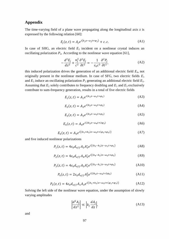
97
Appendix
The time-varying field of a plane wave propagating along the longitudinal axis z is
expressed by the following relation [60]:
( ) ( ) (A1)
In case of SHG, an electric field E2 incident on a nonlinear crystal induces an
oscillating polarization P4. According to the nonlinear wave equation [61],
(A2)
this induced polarization drives the generation of an additional electric field E4, not
originally present in the nonlinear medium. In case of SFG, two electric fields E1
and E3 induce an oscillating polarization P5 generating an additional electric field E5.
Assuming that E2 solely contributes to frequency doubling and E1 and E3 exclusively
contribute to sum-frequency generation, results in a total of five electric fields
( ) ( ) (A3)
( ) ( ) (A4)
( ) ( ) (A5)
( ) ( ) (A6)
( ) (( ) ( )) (A7)
and five induced nonlinear polarizations
( ) (( ) ) (A8)
( ) (( ) ) (A9)
( ) (( ) ) (A10)
( ) ( ) (A11)
( ) (( ) ( )) (A12)
Solving the left side of the nonlinear wave equation, under the assumption of slowly
varying amplitudes
|
| |
| (A13)
and

98
(A14)
results in the following expression
( )
( )
( )
( )
( ( ))
(A15)
Assuming a coherent summation of nonlinear interactions (k = k4 = k5, = 4 = 5,
and = 22 = 1 + 3) the left side of the nonlinear wave equation can be simplified
to
( )
( )
( )
(
) ( )
(A16)
The right side of the nonlinear wave equation results in
(( ) )
(( ) )
(( ) )
( )
(( ) ( ))
(A17)

99
Neglecting all contributions that are not phase-matched results in the following
coupled amplitude equations
( ) (A18)
( ) (A19)
( ) (A20)
(
) (A21)
The equations (A18) - (A20) represent the coupled amplitude equations that take the
depletion of the three fundamental waves into account [27]. The last equation
represents the coupled amplitude equation for simultaneous SHG and SFG. The
corresponding intensity is obtained by integration over the entire crystal length:
( )
(
)∫
(
) (
)
(A22)
Substituting the amplitudes with
| | (A23)
results in
| |
|
|
(A24)
and
(
)
(
)
√
√ (
)
(A25)
respectively. This last equation consists of individual contributions from SHG and
SFG and a third coupling term. Considering the above scenario of matching
frequencies and phases, this third term represents the contribution from occurring

100
interference effects. However, because the superposition of coherent waves does not
alter the total intensity this increase is always compensated [141]. The average
intensity in case of simultaneous nonlinear interactions is therefore always
determined by the summation of the individual contributions.