Embed Size (px)
Citation preview
High-power microwave pulse generator G. 0. White, L. Chen, C. E. Patton, and R. L. Tinkoff Department of Physics, Colorado State University, Fort Collins, Colorado 80523
(Received 14 October 1991; accepted for publication 22 January 1992)
An inexpensive alternative to commercial high-power microwave pulse generators is described. The present high-power microwave pulse generator utilizes a surplus MIT model 3 Mark II hard tube modulator and 2J51 magnetron. The basic design and technical details of the pulse generator are presented. The pulse generator is designed to produce 8.5-9.6 GHz pulses with pulse lengths ranging from 2 to 4 ps, with a nominal power output of 20 kW and a maximum duty cycle of 0.001.
I. INTRODUCTION
High-power microwave pulse generators are important for research in nonlinear high-frequency magnetics and other areas of microwave technology. While such pulse generators are available commercially, the cost is often too high for modest research budgets. The pulse generator de- scribed here is easily fabricated from standard inexpensive components and hard tube modulator/magnetron units available on the surplus market at modest cost.
The high-power microwave pulse generator described here was developed at Colorado State University for use in the high-power microwave characterization of ferrite ma- terials for radar applications. The generator utilizes an MIT model 3 Mark II hard tube modulator and a Ray- theon 2551 magnetron tube. This paper is primarily con- cerned with the workings of the pulse generator and its subsystems. The first section of this report presents a gen- eral overview of the overall pulse generator system. The second section provides a detailed description of the hard tube modulator (HTM) unit, the system interconnects, and the magnetron. The third section gives a description of the pulse generator/sync (PGS) unit which provides high- voltage drive pulses for the pulse generator system.
II. OVERALL SYSTEM
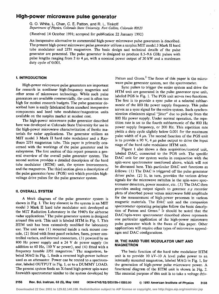
A block diagram of the pulse generator system is shown in Pig. 1. The key element in the system is an MIT model 3 Mark II hard tube modulator unit developed at the MIT Radiation Laboratory in the 1940’s for airborne radar applications.* The pulse generator system is designed around this unit. This unit is labeled HTM in Fig. 1. This HTM unit has been extensively modified for laboratory use. The unit was ( 1) mounted inside a rack mount con- sole, (2) fitted with front panel switches, fuses, power con- trolled variacs, and internal connectors, (3 ) powered by an 800 Hz power supply and a 24 V dc power supply (in addition to 60 Hz, 110 V ac power), and (4) fitted with a frequency tunable 2J51 magnetron.’ The magnetron, la- beled MAG in Fig. 1, feeds a reversed high-power isolator used as an attenuator. Power can be routed to a spectrom- eter, labeled OUTPUT in Fig. 1, or to a DUMMY LOAD. The present system feeds an X-band high-power spin-wave linewidth spectrometer similar to the system developed by
Patton and Green.’ The focus of this paper is the micro- wave pulse generator system, not the spectrometer.
Sync pulses to trigger the entire system and drive the HTM unit are generated in the pulse generator sync unit, labeled PGS in Fig. 1. The PGS unit serves two functions. The first is to provide a sync pulse at a selected subhar- monic of the 800 Hz power supply frequency. This pulse serves as a sync signal for the entire system. Such synchro- nization eliminates signal “jitter” due to pick-up from the 800 Hz power supply. Under normal operation, the repe- tition rate is set to the fourth subharmonic of the 800 Hz power supply frequency, or 200 Hz. This repetition rate yields a duty cycle slightly below 0.001 for the maximum pulse width of 4 ps. The second function of the PGS unit is to provide a 90 V, 4 ps pulse output to drive the input stage of the hard tube modulator HTM unit.
Figure 1 also shows a data acquisition/control unit, labeled DAC, connected to the PGS unit. The specific DAC unit for our system works in conjunction with the spin-wave spectrometer mentioned above, which will not be discussed here. This particular DAC unit functions as follows: ( 1) The DAC is triggered off the pulse generator driver pulse. (2) It, in turn, provides the various driver signals for the microwave switches in the spin-wave spec- trometer detectors, power monitor, etc. (3) The DAC then provides analog output signals to generate x-y recorder plots of absorbed power versus microwave field amplitude for the measurement of high-power processes in various magnetic materials. The DAC unit and the companion spectrometer operating principles follow the basic descrip- tion of Patton and Green.2 It should be noted that the DAC/spin-wave spectrometer described above represents one particular application of the high-power microwave pulse generator which is the focus of this paper. Other applications will require other types of microwave append- ages and DAC configurations.
Ill. THE HARD TUBE MODULATOR UNIT AND MAGNETRON
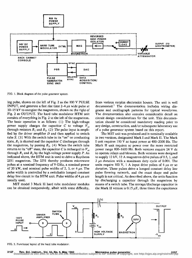
The basic function of the hard tube modulator HTM unit is to provide 10 kV-10 A level pulse power to an internally mounted magnetron, labeled MAG in Fig. 1, for the generation of high-power pulse microwave power. A functional diagram of the HTM unit is shown in Fig. 2. The essential purpose of this unit is to take a voltage driv-
3156 Rev. Sci. Instrum. 63 (5), May 1992 0034-6746/92/053156-l 1$02.00 @ 1992 American Institute of Physics 3156
Downloaded 22 Dec 2001 to 129.82.140.198. Redistribution subject to AIP license or copyright, see http://ojps.aip.org/rsio/rsicr.jsp
,““....-.......1..............
t
. . . . . . . .1. . . . . . . . . . . .~. . . . . . . . . . . . . . . . . . . . . . . . . . . . . . . . . . . . . . .
: R E V E R S E D :
~ o ~ u ; ~ T ; R (HTM) - M A G O U T P U T (TO S P E C T R O M E T E R )
: : ,..........................*......
R A C K C A B I N E T A T T E N U A T O I
C O N S O L E p --ffq Y q P U L S E G E N E R A T O R
E ;p ;ED D A T A ACQUISIT ION/
S Y N C UNIT C O N T R O L
FIG . 1. B lock d i a g r a m of the pu l se g e n e r a t o r system.
i ng pulse, s h o w n o n th e left o f Fig. 2 as th e 1 0 0 V P U L S E INPUT, a n d g e n e r a te a fast r ise tim e 2 - 4 ps w ide pu lse a t 10 - l 5 kV to ene rg i ze th e m a g n e tron, s h o w n o n th e r ight o f Fig. 2 as O U T P U T . T h e h a r d tu b e m o d u lator H T M uni t consists o f every th ing in Fig. 2 to th e left o f th e m a g n e tron. T h e bas ic o p e r a tio n is as fol lows: ( 1 ) T h e h igh-vo l tage p o w e r supp ly cha rges th e capaci tor C to vo l tage V ,, th r o u g h resistors R , a n d RZ. (2 ) T h e pu lse i n p u t is a m p li- fie d by th e dr iver a m p lifie r D a n d th e n a p p l i e d to switch tu b e S . (3 ) W ith th e switch tu b e in its “o n ” o r c o n d u c tin g sta te , R r is shor ted a n d th e capaci tor C d ischarges th r o u g h th e m a g n e tron, by pass ing RZ. (4 ) W h e n th e switch tu b e r e tu rns to its “o ff’ sta te , th e capaci tor C is r e c h a r g e d to V ,, th r o u g h R, a n d R, by th e h igh-vo l tage p o w e r supp ly P . As ind ica ted a b o v e , th e H T M uni t is u s e d to dr ive a Ray theon 2 J 5 1 m a g n e tron. T h e 2 5 5 1 th e r e b y p r o d u c e s m ic rowave pu lses a t a n o m inal f requency o f 9 G H z , a n o m inal p o w e r o f 2 0 k W , a n d n o m inal pu lse widths o f 2 , 3 , o r 4 ps. T h e pu lse width is c o n tro l led by a swi tchable l u m p e d constant de lay l ine circuit in th e H T M unit. P u lse widths o f 4 ~ C L S a r e usual ly u s e d .
M IT m o d e l 3 M a r k II h a r d tu b e m o d u lator m o d u les c a n b e o b ta i n e d inexpensively , a lbei t wi th s o m e difficulty,
f rom var ious surp lus e lect ronics h o u s e s . T h e uni t is wel l d o c u m e n te d .’ T h e d o c u m e n ta tio n inc ludes wi r ing d ia - g r a m s a n d osc i l lograph p a tte rns fo r typ ical w a v e fo r m s . T h e d o c u m e n ta tio n a lso c o n ta ins cons ide rab le d e tai l o n circuit des ign cons idera t ions fo r th e unit. This d o c u m e n - ta tio n shou ld b e cons ide red m a n d a tory r e a d i n g pr io r to a n y des ign , construct ion, a n d /o r s u b s e q u e n t l a b o r a tory u s e o f a pu lse g e n e r a to r system b a s e d o n th is r e p o r t.
T h e M IT uni t was p r o d u c e d a n d is n o m inal ly ava i lab le in two vers ions, d e s i g n a te d M a r k I a n d M a r k II. T h e M a r k I uni t requ i res 1 1 0 V ac i n p u t p o w e r a t 4 0 0 - 2 0 0 0 Hz. T h e M a r k II uni t requ i res ac p o w e r ove r th e m o r e restr icted p o w e r r a n g e 8 0 0 - 1 6 0 0 Hz. B o th vers ions requ i re 2 4 V dc to o p e r a te re lays a n d b lowers . B o th vers ions w e r e d e s i g n e d to supp ly 1 2 kV , 1 2 A m a g n e t ron dr ive pu lses o f 0 .5 , 1 , a n d 2 ~ L S d u r a tio n with a m a x i m u m d u ty cycle o f 0 .0 0 1 . T h e uni ts requ i re 1 0 0 V , 1 A i n p u t dr ive pu lses o f 4 ~ L S o r so d u r a tio n . T h e s e pu lses dr ive a l u m p e d constant de lay l ine pu lse fo r m i n g n e twork, a n d th e exact s h a p e a n d pu lse l e n g th is n o t critical. As desc r ibed a b o v e , th e uni ts fu n c tio n by d ischarg ing a capaci tor th r o u g h th e m a g n e t ron by m e a n s o f a switch tu b e . T h e sto r a g e /d i scharge capaci tor in th e M a r k II vers ion is 0 .1 5 p F , th r e e tim e s th e capac i tance
P U L S E
FIG . 2. Func t iona l layout of the h a r d t u b e modu la to r .
3 1 5 7 Rev. Sci. Instrum., Vol . 63 , No . 5, M a y 1 9 9 2
I/c
H I G H V O L T A G E S U P P L Y
Mic rowave pu l se g e n e r a t o r 3 1 5 7 Downloaded 22 Dec 2001 to 129.82.140.198. Redistribution subject to AIP license or copyright, see http://ojps.aip.org/rsio/rsicr.jsp
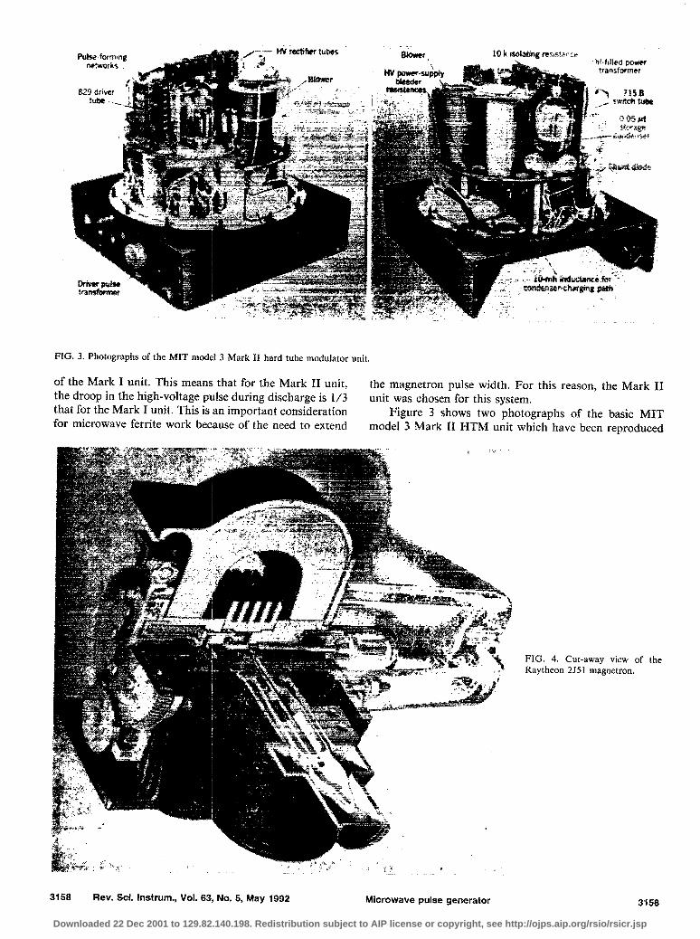
FIG. 3. Photographs of the MIT model 3 Mark II hard tube modulator unit
of the Mark I unit. This means that for the Mark II unit, the droop in the high-voltage pulse during discharge is l/3
the magnetron pulse width. For this reason, the Mark II
that for the Mark I unit. This is an important consideration unit was chosen for this system.
for m icrowave ferrite work because of the need to extend Figure 3 shows two photographs of the basic M IT
mode1 3 Mark II HTM unit which have been reproduced
FIG. 4. Cut-away view of Raytheon 2J51 magnetron.
the
3158 Rev. Sci. Instrum., Vol. 63, No. 5, May 1992 Micrawave pulse generator 3158
Downloaded 22 Dec 2001 to 129.82.140.198. Redistribution subject to AIP license or copyright, see http://ojps.aip.org/rsio/rsicr.jsp
L
soon 250mH
I
3.3kQ: I
- - -’
, -65OV I i 8 I I 1 If II 0 I I 0.3pF 0.3pF I
I 8
0 72 I
, Es24 I t t
t I I 1 I I I I , 1 SOOHz 1 OOVAC I
I 1 Low voltage power supply J
Storage end Filter Capacitors
r
la ______ mm-mm-- ~~~~~~~I - m m - - -. 0 Pulse mo”itor
to magnetron fi lament
-i O.lpF 4-a 2OOf t Spark gep
0 magnetron
High Voltage Transformer
FIG. 5. Overall functional sche- matic of the hard tube modula- tor.
from G lasoe.’ The photographs are not particularly crisp, voltage fi lament/cathode is mounted axially through one but the basic components can be seen with reasonable clar- end of the magnetron biasing magnet assembly. The ity. F igure 4 shows a cut-away view of the 255 1 magnetron, f i lament/cathode connections are through the two terminal reproduced from Smith.3 As shown in F ig. 4, the high- high-voltage glass insulators in the top of F ig. 4. The mag-
3159 Rev. Sci. Instrum., Vol. 63, No. 5, May 1992 Microwave pulse generator 3159 Downloaded 22 Dec 2001 to 129.82.140.198. Redistribution subject to AIP license or copyright, see http://ojps.aip.org/rsio/rsicr.jsp
II TB4
1 2 3 4 5
33kn
'i
O.OluF
I 130kQ 130kR
I
II /I 0.3pF 0.3~F
3824
LdIEzqw jyd5id” tl 4
T3 I
8 9 10 11
TB4-A
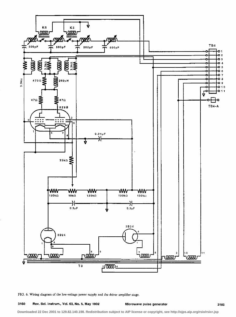
FIG. 6. Wiring diagram of the low-voltage power supply and the driver amplifier stage.
3160 Rev. Sci. Instrum., Vol. 63, No. 5, May 1992 Microwave pulse generator 3160
Downloaded 22 Dec 2001 to 129.82.140.198. Redistribution subject to AIP license or copyright, see http://ojps.aip.org/rsio/rsicr.jsp
TB4
r O.O,pF
-+--I
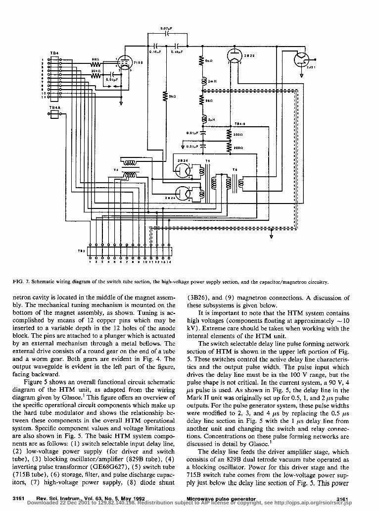
FIG. 7. Schematic wiring diagram of the switch tube section, the high-voltage power supply section, and the capacitor/magnetron circuitry.
netron cavity is located in the m iddle of the magnet assem- bly. The mechanical tuning mechanism is mounted on the bottom of the magnet assembly, as shown. Tuning is ac- complished by means of 12 copper pins which may be inserted to a variable depth in the 12 holes of the anode block. The pins are attached to a plunger which is actuated by an external mechanism through a metal bellows. The external drive consists of a round gear on the end of a tube and a worm gear. Both gears are evident in F ig. 4. The output waveguide is evident in the left part of the figure, facing backward.
(3B26), and (9) magnetron connections. A discussion of these subsystems is given below.
It is important to note that the HTM system contains high voltages (components floating at approximately - 10 kV). Extreme care should be taken when working with the internal elements of the HTM unit.
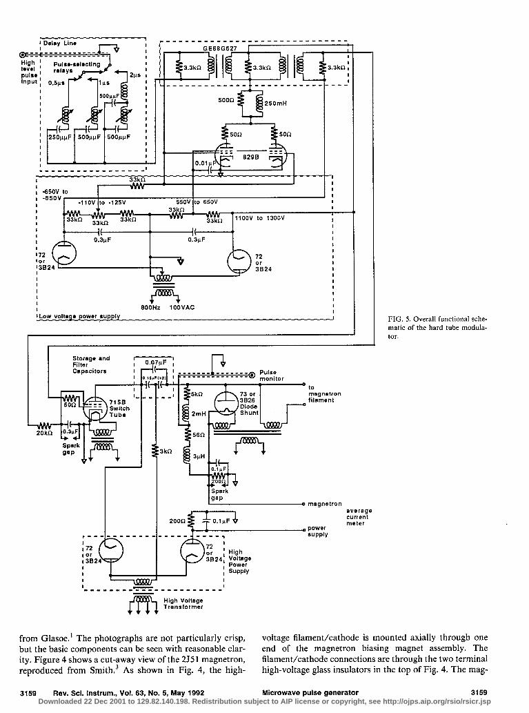
F igure 5 shows an overall functional circuit schematic diagram of the HTM unit, as adapted from the wiring diagram given by G lasoe.’ This figure offers an overview of the specific operational circuit components which make up the hard tube modu lator and shows the relationship be- tween these components in the overall HTM operational system. Specific component values and voltage lim itations are also shown in F ig. 5. The basic HTM system compo- nents are as follows: ( 1) switch selectable input delay line, (2) low-voltage power supply (for driver and switch tube), (3) blocking oscillator/amplifier (829B tube), (4) inverting pulse transformer (GE68G627), (5) switch tube (7 15B tube), (6) storage, filter, and pulse discharge capac- itors, (7) high-voltage power supply, (8) diode shunt
The switch selectable delay line pulse forming network section of HTM is shown in the upper left portion of F ig. 5. These switches control the active delay line characteris- tics and the output pulse width. The pulse input which drives the delay line must be in the 100 V range, but the pulse shape is not critical. In the current system, a 90 V, 4 ,us pulse is used. As shown in F ig. 5, the delay line in the Mark II unit was originally set up for 0.5, 1, and 2 ps pulse outputs. For the pulse generator system, these pulse widths were mod ified to 2, 3, and 4 ps by replacing the 0.5 ps delay line section in F ig. 5 with the 1 ~LS delay line from another unit and changing the switch and relay connec- tions. Concentrations on these pulse forming networks are discussed in detail by G lasoe.’
The delay line feeds the driver amp lifier stage, which consists of an 829B dual tetrode vacuum tube operated as a blocking oscillator. Power for this driver stage and the 715B switch tube comes from the low-voltage power sup- ply just below the delay line section of Fig, 5. This power
3161 Rev. Sci. Instrum., Vol. 63, No. 5, May 1992 Microwave pulse generator 3161 Downloaded 22 Dec 2001 to 129.82.140.198. Redistribution subject to AIP license or copyright, see http://ojps.aip.org/rsio/rsicr.jsp
us1 F3 11OVAC POWER lNPUT
PL2 o---o 1iov
POWER o OUTPUT
S9A
RECTIFIER
F5 1A ,
J2 TO PULSE GENERATOR o TRIGGER INPUT fl
ELGAR 2518
AC POWER SOURCE 0 TO 130V 800Hz AC POWER OUTPUT
: MULTIPI E OUTLET STRIP
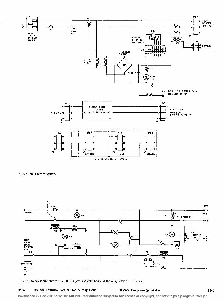
FIG. 8. Main power section.
24VDC
< < I. I. ,’ ,’ 1 l .,s 1 l .,s
FIL PRIMARY
TB3 TB3 015 15 OS 3
12
SOOHI MAIN POWER S W
s3
HTM sOOHz MAIN POWER
: I “(+jg I ; 4 , *wT2
FIG. 9. Overview circuitry for the 800 Hz power distribution and the relay interlock circuitry.
3162 Rev. Sci. Instrum., Vol. 63, No. 5, May 1992 Microwave pulse generator 3162 Downloaded 22 Dec 2001 to 129.82.140.198. Redistribution subject to AIP license or copyright, see http://ojps.aip.org/rsio/rsicr.jsp
: :
PL3 : PULSE DURATION
A 24VDC w
Fl 3A
OHAGNETRO ;FILAMENT -CONTROL : : I
: HIGH : VOLTAGE . CI\“TOnl
t LOWER FRONT PANEL UPPER FRONT PANEL
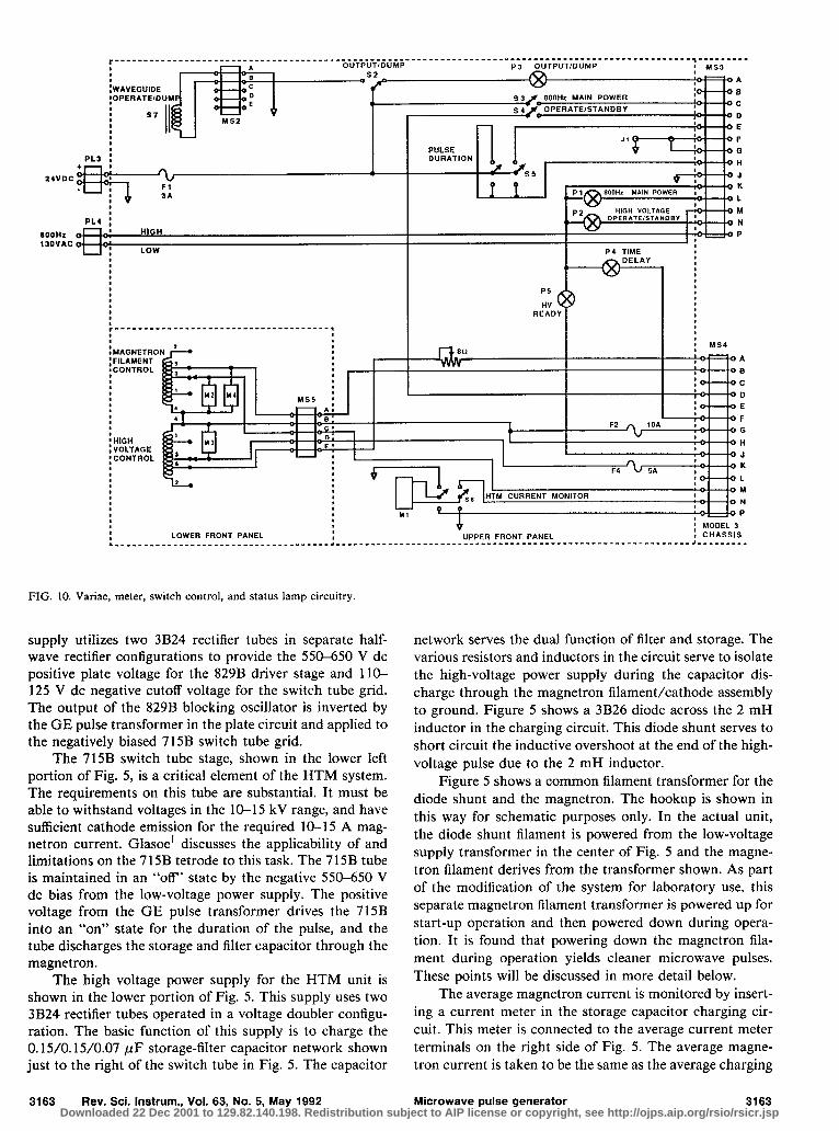
FIG. 10. Variac, meter, switch control, and status lamp circuitry.
supply utilizes two 3B24 rectifier tubes in separate half- wave rectifier configurations to provide the 550-650 V dc positive plate voltage for the 829B driver stage and llO- 125 V dc negative cutoff voltage for the switch tube grid. The output of the 829B blocking oscillator is inverted by the GE pulse transformer in the plate circuit and applied to the negatively biased 715B switch tube grid.
The 715B switch tube stage, shown in the lower left portion of Fig. 5, is a critical element of the HTM system. The requirements on this tube are substantial. It must be able to withstand voltages in the 10-15 kV range, and have sufficient cathode emission for the required 10-15 A mag- netron current. Glasoe’ discusses the applicability of and lim itations on the 715B tetrode to this task. The 715B tube is maintained in an “off’ state by the negative 550-650 V dc bias from the low-voltage power supply. The positive voltage from the GE pulse transformer drives the 715B into an “on” state for the duration of the pulse, and the tube discharges the storage and filter capacitor through the magnetron.
The high voltage power supply for the HTM unit is shown in the lower portion of Fig. 5. This supply uses two 3B24 rectifier tubes operated in a voltage doubler configu- ration. The basic function of this supply is to charge the 0.15/O. 15/0.07 PF storage-filter capacitor network shown just to the right of the switch tube in Fig. 5. The capacitor
3163 Rev. Sci. Instrum., Vol. 63, No. 5, May 1992
network serves the dual function of filter and storage. The various resistors and inductors in the circuit serve to isolate the high-voltage power supply during the capacitor dis- charge through the magnetron filament/cathode assembly to ground. Figure 5 shows a 3B26 diode across the 2 mH inductor in the charging circuit. This diode shunt serves to short circuit the inductive overshoot at the end of the high- voltage pulse due to the 2 mH inductor.
Figure 5 shows a common filament transformer for the diode shunt and the magnetron. The hookup is shown in this way for schematic purposes only. In the actual unit, the diode shunt filament is powered from the low-voltage supply transformer in the center of Fig. 5 and the magne- tron filament derives from the transformer shown. As part of the modification of the system for laboratory use, this separate magnetron filament transformer is powered up for start-up operation and then powered down during opera- tion. It is found that powering down the magnetron fila- ment during operation yields cleaner m icrowave pulses. These points will be discussed in more detail below.
The average magnetron current is monitored by insert- ing a current meter in the storage capacitor charging cir- cuit. This meter is connected to the average current meter terminals on the right side of Fig. 5. The average magne- tron current is taken to be the same as the average charging
Microwave pulse generator 3163 Downloaded 22 Dec 2001 to 129.82.140.198. Redistribution subject to AIP license or copyright, see http://ojps.aip.org/rsio/rsicr.jsp
K3 High Volta
I II I Time
TB5 K4 Delay
II,. t I L-I , 1 1’2 P
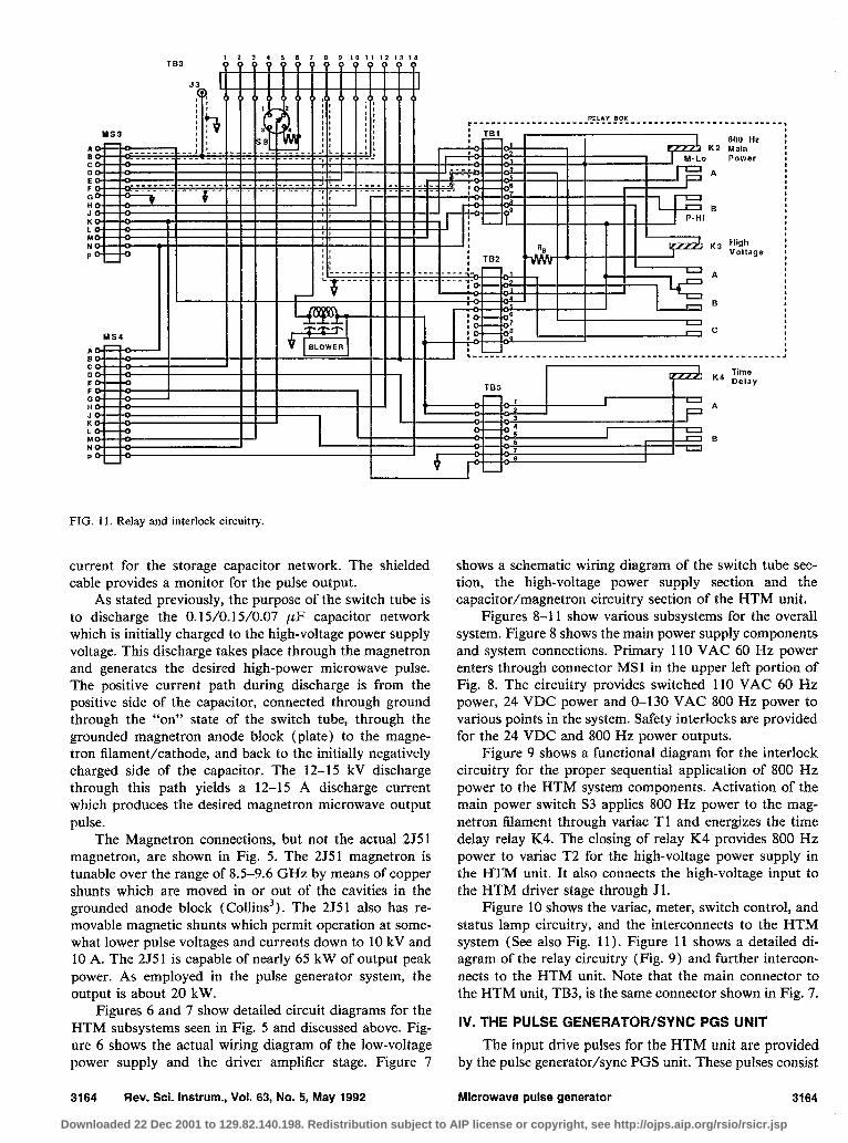
FIG. 11. Relay and interlock circuitry.
current for the storage capacitor network. The shielded cable provides a mon itor for the pulse output.
As stated previously, the purpose of the switch tube is to discharge the 0.15/0.15/0.07 PF capacitor network which is initially charged to the high-voltage power supply voltage. This discharge takes place through the magnetron and generates the desired high-power m icrowave pulse. The positive current path during discharge is from the positive side of the capacitor, connected through ground through the “on” state of the switch tube, through the grounded magnetron anode block (plate) to the magne- tron fi lament/cathode, and back to the initially negatively charged side of the capacitor. The 12-15 kV discharge through this path yields a 12-15 A discharge current which produces the desired magnetron m icrowave output pulse.
The Magnetron connections, but not the actual 2551 magnetron, are shown in F ig. 5. The 2551 magnetron is tunable over the range of 8.5-9.6 GHz by means of copper shunts which are moved in or out of the cavities in the grounded anode block ( Collins3). The 2551 also has re- movable magnetic shunts which permit operation at some- what lower pulse voltages and currents down to 10 kV and 10 A. The 2551 is capable of nearly 65 kW of output peak power. As emp loyed in the pulse generator system, the output is about 20 kW.
F igures 6 and 7 show detailed circuit diagrams for the HTM subsystems seen in F ig. 5 and discussed above. F ig- ure 6 shows the actual wiring diagram of the low-voltage power supply and the driver amplifier stage. F igure 7
3164 Rev. Sci. Instrum., Vol. 63, No. 5, May 1992
shows a schematic wiring diagram of the switch tube sec- tion, the high-voltage power supply section and the capacitor/magnetron circuitry section of the HTM unit.
F igures 8-l 1 show various subsystems for the overall system. F igure 8 shows the ma in power supply components and system connections. Primary 110 VAC 60 Hz power enters through connector MS1 in the upper left portion of F ig. 8. The circuitry provides switched 110 VAC 60 Hz power, 24 VDC power and O-130 VAC 800 Hz power to various points in the system. Safety interlocks are provided for the 24 VDC and 800 Hz power outputs.
F igure 9 shows a functional diagram for the interlock circuitry for the proper sequential application of 800 Hz power to the HTM system components. Activation of the ma in power switch S3 applies 800 Hz power to the mag- netron filament through variac T l and energizes the time delay relay K4. The closing of relay K4 provides 800 Hz power to variac T2 for the high-voltage power supply in the HTM unit. It also connects the high-voltage input to the HTM driver stage through Jl.
F igure 10 shows the variac, meter, switch control, and status lamp circuitry, and the interconnects to the HTM system (See also F ig. 11). F igure 11 shows a detailed di- agram of the relay circuitry (Fig. 9) and further intercon- nects to the HTM unit. Note that the ma in connector to the HTM unit, TB3, is the same connector shown in F ig. 7.
IV. THE PULSE GENERATOR/SYNC PGS UNIT The input drive pulses for the HTM unit are provided
by the pulse generator/sync PGS unit. These pulses consist
Microwave pulse generator 3164
Downloaded 22 Dec 2001 to 129.82.140.198. Redistribution subject to AIP license or copyright, see http://ojps.aip.org/rsio/rsicr.jsp
DIVIDE BY N CIRCUIT IC
/
(FRONT PANEL)
A : BCD IN
‘lo ’ ’ ’ SWITCH
6 SYNC OUT
(REAR J9 CHASSIS)
:“yNc~, p ‘1;; “3 DRl:EFi
I 0 I HV PULSE 1116A ^v 1 ;;;;:;
V
P I +I- 12V DC
4. 11v DC POV d POWER ki - 1..”
V
SUPPLY
19 9
t12ov
0
+12OV DC POWER SIJPPLY
0 (I GND
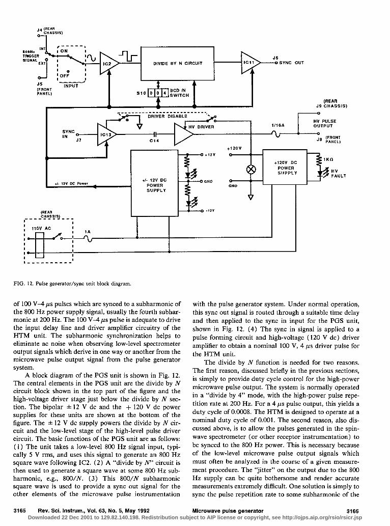
FIG. 12. Pulse generator/sync unit block diagram.
of 100 V-4 ps pulses which are synced to a subharmonic of the 800 Hz power supply signal, usually the fourth subhar- mon ic at 200 Hz. The 100 V4 ,us pulse is adequate to drive the input delay line and driver amp lifier circuitry of the HTM unit. The subharmonic synchronization helps to eliminate ac noise when observing low-level spectrometer output signals which derive in one way or another from the m icrowave pulse output signal from the pulse generator system.
A block diagram of the PGS unit is shown in F ig. 12. The central elements in the PGS unit are the divide by N circuit block shown in the top part of the figure and the high-voltage driver stage just below the divide by N sec- tion. The bipolar f 12 V dc and the + 120 V dc power supplies for these units are shown at the bottom of the figure. The f 12 V dc supply powers the divide by N cir- cuit and the low-level stage of the high-level pulse driver circuit. The basic functions of the PGS unit are as follows: ( 1) The unit takes a low-level 800 Hz signal input, typi- cally 5 V rms, and uses this signal to generate an 800 Hz square wave following IC2. (2) A “divide by jV” circuit is then used to generate a square wave at some 800 Hz sub- harmonic, e.g., 800/N. (3) This 800/N subharmonic square wave is used to provide a sync out signal for the other elements of the m icrowave pulse instrumentation
3165 Rev. Sci. Instrum., Vol. 63, No. 5, May 1992
with the pulse generator system. Under normal operation, this sync out signal is routed through a suitable time delay and then applied to the sync in input for the PGS unit, shown in F ig. 12. (4) The sync in signal is applied to a pulse forming circuit and high-voltage ( 120 V dc) driver amp lifier to obtain a nominal 100 V, 4 ps driver pulse for the HTM unit.
The divide by N function is needed for two reasons. The first reason, discussed briefly in the previous sections, is simply to provide duty cycle control for the high-power m icrowave pulse output. The system is normally operated in a “divide by 4” mode, with the high-power pulse repe- tition rate at 200 Hz. For a 4 ps pulse output, this yields a duty cycle of 0.0008. The HTM is designed to operate at a nominal duty cycle of 0.001. The second reason, also dis- cussed above, is to allow the pulses generated in the spin- wave spectrometer (or other receptor instrumentation) to be synced to the 800 Hz power. This is necessary because of the low-level m icrowave pulse output signals which must often be analyzed in the course of a given measure- ment procedure. The “jitter” on the output due to the 800 Hz supply can be quite bothersome and render accurate measurements extremely difficult. One solution is simply to sync the pulse repetition rate to some subharmonic of the
Microwave pulse generator 3165 Downloaded 22 Dec 2001 to 129.82.140.198. Redistribution subject to AIP license or copyright, see http://ojps.aip.org/rsio/rsicr.jsp
800 Hz ac power. The divide by N sync circuitry allows both objectives to be accomplished.
V. DISCUSSION
An inexpensive, easily fabricated high-power micro- wave pulse generator has been described. The pulse gener- ator utilizes an MIT model 3 Mark II hard tube modulator and a Raytheon 2J51 magnetron tube, both of which can be located on the surplus electronics market. Circuit dia- grams and fundamental electronic analyses for the pulse
3166 Rev. Sci. Instrum., Vol. 63, No. 5, May 1992
generator and its subsystems are provided. The pulse gen- erator has been used for research in high-power microwave magnetics.
‘G. N. Glasoe, Pulse Generators, edited by G. N. Glasoe and J. V. Lebacq, MIT Radiation Laboratory Series, Vol. 5 (McGraw-Hill, New York, 19481, Sec. 5-1, pp. 140-152.
‘3. J. Green and C. E. Patton, Rev. Sci. Instrum. 42, 193 (1971). 3A. G. Smith, Microwave Magnetrons, edited by G. B. Collins, MIT Radiation Laboratory Series, Vol. 6 (McGraw-Hill, New York, 1948), Sec. 19-l 1, pp. 778-780.
Microwave pulse generator 3166
Downloaded 22 Dec 2001 to 129.82.140.198. Redistribution subject to AIP license or copyright, see http://ojps.aip.org/rsio/rsicr.jsp