Embed Size (px)
Citation preview

High Powered Go-Kart Drive
A Baccalaureate thesis submitted to the School of Dynamic Systems
College of Engineering and Applied Science University of Cincinnati
in partial fulfillment of the
requirements for the degree of
Bachelor of Science
in Mechanical Engineering Technology
by
Student Chris Williams
April 2013
Thesis Advisor: Ahmed Elgafy, PhD

High Powered Go-Kart Drive Chris Williams
ii
ACKNOWLEDGEMENTS
I would like to dedicate this project to my wonderful friends and family that have always
supported me during this journey.
TABLE OF CONTENTS
ACKNOWLEDGEMENTS ...................................................................................................... II
TABLE OF CONTENTS .......................................................................................................... II
LIST OF FIGURES ................................................................................................................ III
LIST OF TABLES .................................................................................................................. IV
ABSTRACT ............................................................................................................................. V
INTRODUCTION .................................................................................................................... 1
BACKGROUND .................................................................................................................................................... 1
EXISTING GO-KART DESIGNS ON THE WEB .................................................................. 2
OLDMINIBIKES FORUM GO-KART ......................................................................................................................... 2 COMMERCIALLY MANUFACTURED OFF ROAD BUGGIES .................................................................................... 3
CURRENT GO-KART DESIGN TARGET AREAS .............................................................. 5
DRIVE TRAIN ...................................................................................................................................................... 5 SHIFTING ............................................................................................................................................................ 6 BRAKES .............................................................................................................................................................. 7 STARTER ............................................................................................................................................................ 8
CUSTOMER FEEDBACK, FEATURES, AND OBJECTIVES ............................................. 9
SURVEY ANALYSIS .............................................................................................................................................. 9 PRODUCT FEATURES AND OBJECTIVES ................................................................................................ 10 ENGINEERING CHARACTERISTICS ..................................................................................................................... 11 SCHEDULE AND BUDGET .................................................................................................................................. 12
DESIGN ALTERNATIVES AND SELECTION .................................................................. 14
REVERSE METHODS .......................................................................................................................................... 14 STARTING METHODS ........................................................................................................................................ 16 BRAKES ............................................................................................................................................................ 19
THE FINAL DESIGN ............................................................................................................ 20
FINAL ASSEMBLY CONFIGURATION.................................................................................................................. 20 EXISTING FRAME WELDMENT .......................................................................................................................... 21 AXLE ASSEMBLY .............................................................................................................................................. 22 JACKSHAFT ASSEMBLY .................................................................................................................................... 23 STARTER ASSEMBLY ........................................................................................................................................ 24 REVERSE MOTOR ASSEMBLY ........................................................................................................................... 25 BRAKE ASSEMBLY ........................................................................................................................................... 26

High Powered Go-Kart Drive Chris Williams
iii
CALCULATIONS .................................................................................................................. 27
POWER, TORQUE, SPEED .................................................................................................................................. 27 SAFETY FACTOR ............................................................................................................................................... 29 BRAKES ............................................................................................................................................................ 30 AXLE STRESS ................................................................................................................................................... 33 JACK SHAFT ASSEMBLY ................................................................................................................................... 37 REVERSE ELECTRIC MOTOR REQUIREMENTS ................................................................................................... 39
FABRICATION & TESTING ................................................................................................ 43
FABRICATION ................................................................................................................................................... 43 TESTING, RESULTS, AND CHANGES .................................................................................................................. 44
CONCLUSION ....................................................................................................................... 46
WORKS CITED ..................................................................................................................... 48
APPENDIX A RESEARCH .................................................................................................. A1
APPENDIX B SURVEY WITH RESULTS .......................................................................... B1
APPENDIX C QFD ................................................................................................................ C1
APPENDIX D PRODUCT OBJECTIVES ............................................................................ D1
APPENDIX E SCHEDULE ................................................................................................... E1
APPENDIX F BUDGET ........................................................................................................ F1
APPENDIX G DETAIL DRAWINGS .................................................................................. G1
APPENDIX H SPREAD SHEETS ........................................................................................ H1
LIST OF FIGURES Figure 1 - Overall Go-Kart Before Redesign Effort. ................................................................ 1
Figure 2 - OldMiniBikes Forum Go-Kart ................................................................................ 2
Figure 3 - Zircon 150cc (2) ....................................................................................................... 3
Figure 4 Hammer Head Buggy 250cc (3) ................................................................................. 3
Figure 5 - BMS 400cc (4) ......................................................................................................... 4
Figure 6 - Drive Sprocket Hub Connection Figure 7 - Brake Disc Hub Connection ......... 5
Figure 8 - Existing Drive System Figure 9 - Engine Shift Lever ................................ 5
Figure 10 - Driver Shift Lever Figure 11 - Clutch Cable Union ........................................ 6
Figure 12 – Hardlined Master Cylinder .................................................................................... 7
Figure 13 – Softlined Caliper .................................................................................................... 7
Figure 14 - Current Starter Location Figure 15 - Jackshaft Starter ..................................... 8
Figure 16 – High Hp F-N-R Gearbox (9) ............................................................................... 14
Figure 17 – High HP F-N-R Application (10) ........................................................................ 15
Figure 18 – Comet F-N-R Gearbox Schematic (11) ............................................................... 15
Figure 19- Original Design Sketch ......................................................................................... 17
Figure 20 – Starter Shaft Assembly (10) ................................................................................ 18
Figure 21 - Drive Train Assembly .......................................................................................... 20

High Powered Go-Kart Drive Chris Williams
iv
Figure 22 - Original Frame Weldment.................................................................................... 21
Figure 23 - Modified Frame Weldment .................................................................................. 21
Figure 24 - Axle Assembly ..................................................................................................... 22
Figure 25 - Un-mounted Jackshaft Assembly ......................................................................... 23
Figure 26 - Mounted Jackshaft Assembly .............................................................................. 23
Figure 27 - Starter Assembly and GM Starter (14) ................................................................. 24
Figure 28 - Reverse Motor and Mount/Cover......................................................................... 25
Figure 29 - Brake Assembly ................................................................................................... 26
Figure 30 – Safety Factor ........................................................................................................ 29
Figure 31 – Pedal Ratio Diagram (11) .................................................................................... 31
Figure 32 – Hydraulic Force Diagram (12) ............................................................................ 31
Figure 33 – Endurance Strength Sn, vs. Tensile Strength Su (11) ......................................... 34
Figure 34 – Axle Loading Dimensions ................................................................................... 34
Figure 35 – Load, Shear, Moment Diagram ........................................................................... 35
Figure 36 – Bolt Shear (15) .................................................................................................... 38
Figure 37 – AMPFLOW A40-300 Motor Specifications (10)................................................ 42
Figure 38 – Starter Shaft Splines ............................................................................................ 43
Figure 39 –Mock Up ............................................................................................................... 43
Figure 40 – Starter High-Torque............................................................................................. 44
Figure 41 – Final Starter Configuration .................................................................................. 45
Figure 42 – Reverse Gearing .................................................................................................. 45
Figure 43 – Side View ............................................................................................................ 46
Figure 44 – Rear Side ............................................................................................................. 46
Figure 45 - Front ..................................................................................................................... 47
Figure 46 - Rear ...................................................................................................................... 47
LIST OF TABLES Table 1 - Weighted Results ....................................................................................................... 9
Table 2 – Engineering Characteristics .................................................................................... 11
Table 3 – Schedule .................................................................................................................. 12
Table 4 - Budget...................................................................................................................... 13
Table 5 - Gear Ratios .............................................................................................................. 27
Table 6 – Force Constants....................................................................................................... 39

High Powered Go-Kart Drive Chris Williams
v
ABSTRACT
An old go-kart had tremendous power but was inoperable and would not have lasted under
much use. Redesign and fabrication processes are needed to make it practical and usable.
Fifteen people were surveyed and the top three most critical items were safe, easy to
maneuver and reliable. This prompted the need for the good brakes, reverse and a detailed
look at all of the components used in the drive train.
Research was done on other go-karts and their features and ways to reverse and start the
engines. The response from, the surveys, interviews, and market research drove the design
phases. The design was sketched out and then after careful consideration a final design
initiative was determined. The target areas were electric start and reverse, hydraulic brakes
and solid rear axle. 3D CAD models were created and then they were analyzed for stresses.
Once the materials were sized and selected the fabrication process began.
During the fabrication and testing process some information was gained and the design was
modified for further reliability and functionality. The go-kart now has power and is
functional and reliable. The brakes work well and it is safe for the user. The go-kart is
overall a sound machine and will provide years of continued service to the rider.

High Powered Go-Kart Drive Chris Williams
1
INTRODUCTION
BACKGROUND
Figure 1 features a high-powered off road go-kart, was created by modifying an existing
frame to add suspension and a 500cc Yamaha dirt-bike engine. This engine produces 55hp
compared to the other 5-20hp common 4 cycle go cart engine. This engine has a built in 5
speed transmission which requires manual shifting. The braking system came from an old
motorcycle and was not sufficient. Due to the time constraints and lack of knowledge for
engineering practices, the drive train was designed with no ability to be disassembled. There
are also many other flaws with the design, such as unprotected and weak linkages.
Figure 1 - Overall Go-Kart Before Redesign Effort.
The objective of this project is to apply engineering principles to improve the design by
calculating the forces applied to the components. These forces will be used to select part
sizes, and purchase the correct components, while correcting the linkage problems with the
current design. In the current state, the go-kart is not functional and very unreliable. Using
the results from the survey and engineering tools to prioritize target areas, the kart’s
drivetrain can be redesigned. The outcome will be a fully functioning go-kart drive system
that will stand up to years of use.

High Powered Go-Kart Drive Chris Williams
2
EXISTING GO-KART DESIGNS ON THE WEB
OLDMINIBIKES FORUM GO-KART
This forum on Old MiniBikes.com features a homemade version of a go-kart dirt-bike engine
combination this shown below in Figure 2 (1). This version uses a 175cc 2-stroke Yamaha
engine to drive it. Although this unit looks to be innovative, it is not going to be reliable and
the components appear to be undersized. The unit also uses parts like differentials and other
components from a lawn mower, and although it works for now, those components are not
rated for the speed or forces created by that engine. After a period of time, this go-kart
design will not be reliable. It does however provide examples of how to actuate the shifter,
gas, and clutch. In this application, cables were used to actuate the clutch, gas, and brakes.
There is a rigid linkage that actuates the shifter.
Figure 2 - OldMiniBikes Forum Go-Kart

High Powered Go-Kart Drive Chris Williams
3
COMMERCIALLY MANUFACTURED OFF ROAD BUGGIES
Most of the manufactured buggies are very similar. The buggies are mostly designed for two
riders, meaning the frames are larger and heavier. They all appear to be well built and
adequately suited for off road traffic as well. The buggies listed below in Appendix A, all
appear to be belt or shaft driven. The Figures 3,4 and 5 are pictures of the go-karts explained
in this section. These photos show the similarities in contrast to the existing design of the
current go-kart. They have a range of transmission set ups between automatic CVT, high-
low, and multiple speed settings. The buggies also have reverse, which makes it very good at
maneuvering. They all use various sized 4 stroke engines to power them and hydraulic disk
brakes.
Figure 3 - Zircon 150cc (2)
Figure 4 Hammer Head Buggy 250cc (3)

High Powered Go-Kart Drive Chris Williams
4
Figure 5 - BMS 400cc (4)
These machines are hard to relate to the go-kart in this design, because designs are not fully
disclosed on the manufacturer web pages. It should be noted that since they all use hydraulic
brakes, which might mean that they would be the premium braking source. Belt drives have
potential to wear quickly and slip when they get wet. Chain drives systems have more solid
connection and have the potential to last a lot longer. They also have the potential to need
less maintenance because they don’t stretch as much and are not as sensitive to temperature.
In this design application, the engine has considerable more horsepower than the
manufactured buggies and would also put tremendous strain on a belt drive system and
would require a more elaborate system to accommodate that much power. Reverse is also a
common denominator between the manufactured buggies. To accomplish this feature, the
design either needs another engine with a built in reverse gear or a separate forward and
reverse gear box. These gearboxes are very expensive and add to the complexity of the
project.

High Powered Go-Kart Drive Chris Williams
5
CURRENT GO-KART DESIGN TARGET AREAS
DRIVE TRAIN
The drive train on this current design needs some thought in order to make match the desired
engineering characteristics, such as reliable, easy to maintain, and adjustable. The first
problem with this drive train is the drive axle and hubs are not designed to be able to be
disassembled for repairs, maintenance, or adjustment. The solid axle and hubs are welded
solid and should be affixed via another method. Otherwise, to remove this axle for any kind
of maintenance or sprocket change would require cutting and remanufacturing all the
components attached to it. A method to attach the hubs to the drive shaft could include
keyways and lock collars, locking bushings, or splined interfaces between the hub and axle.
See figures 6 and 7 below. Analysis also needs to be performed on this axle to ensure proper
sizing and if it can handle the loading applied to it. The raw steel axle and hubs require a
form of treatment or coating to ensure they will not rust as currently shown in the figures.
Figure 6 - Drive Sprocket Hub Connection Figure 7 - Brake Disc Hub Connection
The drive system also requires a chain tensioner to remove slack from the chain. The
tensioner should also provide the proper angle of wrap between the chain and sprocket.
Another reason the chain tensioner is used on this project, is to accommodate a compact
relationship between the drive sprocket on the engine, and the driven sprocket on the shaft.
Analysis needs to be performed on this component and assembly constraints to ensure proper
engineering design techniques.
Figure 8 - Existing Drive System Figure 9 - Engine Shift Lever

High Powered Go-Kart Drive Chris Williams
6
SHIFTING
The current gear selection system consists of a push pull cable attached to a lever at each end
as indicated in Figure 9. One end is manually actuated by the driver then the cable translates
that action to the lever attached to the gear selection shaft on the engine. That system works
well although the method of which the levers are supported and mounted is flawed. The
engine actuator lever needs a better support bracket, which properly supports the load and
maintains proper alignment. The driver operated shift lever shown in Figure 10 does not
have a mechanical stop to prevent the driver to over travel and over load the shift lever arm.
This over loading could cause the system to fail. The actuation of the clutch cable needs to
be redesigned, as of now the cable is very poorly coupled together with the manufacturer’s
cable, see Figure 11. This union needs to be improved or both cables need to be reduced to
one cable actuating the entire system. The cable is currently actuated by the drivers left foot
like in a car. This function will be changed to a hand operated lever mounted to the shift
lever. This would be similar to that of a motorcycle or dirt bike. A continuous cable will be
purchased and remove the union, this will solidify the design and smooth out the operation.
Figure 10 - Driver Shift Lever Figure 11 - Clutch Cable Union

High Powered Go-Kart Drive Chris Williams
7
BRAKES
The brakes of any vehicle are one of the most important functioning components. The brakes
of this vehicle are not operational. These brakes were taken from an older motorcycle then
modified to fit this go-kart. The brake lines were stretched using a modified metal brake line
coupled with a rubber line at the frames hinge point, see Figures 12 & 13. The brakes do not
have the capacity to stop the go-kart, they only slow it down. The brakes need to be properly
sized based by braking calculations and then the correct brakes need to be ordered and
implemented.
Figure 12 – Hardlined Master Cylinder
Figure 13 – Softlined Caliper

High Powered Go-Kart Drive Chris Williams
8
STARTER
The engine on this go-kart uses the kick start method to turn the engine over when starting.
This proposes a problem because the location of the engine and its difficulty to operate the
starter. The starter engine is tucked under the frame and the person starting the engine is
forced to stick their leg in the frame and it makes it difficult to start. This configuration is
greatly undesirable. Figure 14 shows the starter location and how difficult it is to operate.
The old mini bikes go-kart shown in Figure 15 (1) had a similar problem with that go-kart.
That design incorporated the use of a jackshaft to change the location of the kick start lever.
This design is shown in Figure 15. The design could also be modified by converting the
starter to an electric start by, adding a shaft to the engines starter shaft. Then, add a sprocket
to that shaft and couple it with a chain attached to another sprocket on an electric motor.
Figure 14 - Current Starter Location Figure 15 - Jackshaft Starter

High Powered Go-Kart Drive Chris Williams
9
CUSTOMER FEEDBACK, FEATURES, AND OBJECTIVES
SURVEY ANALYSIS
Fifteen surveys were returned from people who ranged from engineers to outdoors power
sports enthusiasts. Several of the people surveyed are listed in Appendix A; Mr. Harris (5),
Mr. House (6), Mr. Davish (7), and Mr. Taveras (8). Their input was also used to create the
target areas for the survey. Those individuals have design experience and in most cases
power sports experience. All noted this is a large amount of horsepower compared to most
go-karts available. They say concentrate on linkages working well and would like to see
reverse. They are concerned with the brakes, starting, and axle loading. In table 1, there are
several columns that are modifiers to adjust the relative weight. The first column is the
customer importance this is derived from the results of the customer responses. The next
column is the designer’s multiplier which allows the designer to place their importance on
the relative weight. The designer put greater emphasis on safety compared to anything else.
The responses from the survey regarding the current satisfaction levels with the current
design make up the current satisfaction multiplier. The safety is the number one priority by
all parties involved which is reflected by the highest relative weight. The planned
satisfaction is the target of the designer to meet the audience’s wants and needs. The
improvement ratio indicates the change from the current design versus the planned
satisfaction.
Table 1 - Weighted Results

High Powered Go-Kart Drive Chris Williams
10
PRODUCT FEATURES AND OBJECTIVES
The product objectives are created by the list of customer features questioned about in the
survey. This list of product objectives provides a firmer definition of the needs of the
customer. The objectives listed below helps the designer to insure that those needs are met
through the proper use of engineering characteristics. These objectives help ensure that the
customer input is not forgotten and are used to establish a game plan for the design. The
results from the surveys, interviews in Appendix A, and the objectives are what are required
to get an optimal design.
1. Safe 18%
a. Chain guards
b. Pinch Point Guards
c. Design for forces and select proper components for adequate braking.
2. Easy to Maneuver 15%
a. Design reversing gear to allow for tight quarter maneuvering.
b. Foot Controls to keep hands free for driving and operating shifter.
c. Hand Shift Lever-ergonomically located for comfortable gear selection.
3. Reliable 13%
a. Reliable measured by component life and proper design criteria in the following
specs.
i. Bearings
ii. Sprockets
iii. Chain
iv. Shafts
4. Durable 11%
a. Determine a design factor to use in calculations to prevent failures.
b. Rust-resistant material selection
c. Adequately size purchased components based on force/loading calculations in
conjunction with safety factor to prevent part failure.
5. Easy to Maintain 10%
a. Through proper component selection by designing for long lifetimes the machine
maintenance time is kept at a minimum of 30 minutes or less per service.
6. Easy to Repair 9%
a. Design for reduced time in disassembly for reduced repair times.
b. Design using standard components for fast part turn around in the event of a failed or
worn part. It shall be quick to replace.
7. Easy to Start 8%
a. Design the incorporation if engine allows for incorporation of electric starter.
b. If the engine doesn’t allow for the incorporation of electric starter design for an easy
to use starting lever.
8. Cost 8%
a. Total design and build cost less than $2000
9. Easy to Adjust 8%
a. Components
b. Access
c. Tensioners

High Powered Go-Kart Drive Chris Williams
11
ENGINEERING CHARACTERISTICS
The Quality Function Deployment Analysis (QFD) shown in Appendix C. is used to
determine the important characteristics that impact the design and focus on areas for
improvement. From the analysis, the controls, brakes, and reverse, were the top three
targeted characteristics. The brakes are another area where the consumer felt needs to be
reliable and function properly. When it comes to reverse, accomplishing this task the design
may need to use another motor or a gearbox. This again is another tool for the designer to
use when finalizing the game plan for design.
Table 2 – Engineering Characteristics

High Powered Go-Kart Drive Chris Williams
12
SCHEDULE AND BUDGET
The schedule in Table-3 shows the timeline which allows the designer to track the design.
The schedule is a crucial part to maintaining the success of a project. This is the plan that
designates progress. This progress is directly tied to the budget on a project. In most design
firms, the longer it takes to get a project to completion, the more overhead is applied to the
budget. The budget is shown in Table- 4 which indicates the cost of the majority of the
components needed to complete this project. Labor hours are not associated with this project
because any work provided by outside sources will be absorbed in the machining budget.
Table 3 – Schedule

High Powered Go-Kart Drive Chris Williams
13
Table 4 - Budget

High Powered Go-Kart Drive Chris Williams
14
DESIGN ALTERNATIVES AND SELECTION
REVERSE METHODS
As stated in the product objective easy to maneuver was second on the list for items of design
focus. This design would have could have utilized a Forward – Neutral – Reverse gearbox
as the method to change between the Forward and Reverse instead of using the electric motor
as selected in the final design. Some versions would allow the direct single chain design
alternative, by coupling the chain to the F-N-R gearbox then mounting the axles directly to
the left and right outputs on the gear box. See Figure 16. Tightening the chain could then be
accomplished by adjusting the distance between the engine and axle assembly. This would
allow for only travel required in the horizontal plane versus the horizontal and vertical planes
as determined in the final design. These gearboxes are made to with stand 100+ Hp but
range in price from $1500-$2000. Figure 17 shows this type of gearbox with an integrated
brake in a similar project. This cost is prohibitive to the budgetary constraints of the project.
Another version of the F-N-R is manufactured by Comet Industries this would take the place
of the jackshaft in the final assembly and also incorporate a F-N-R functionality. See Figure
18 for schematic. The Comet design would not work for this application because it had a
max Hp rating of 16Hp and the engine in this design produces 55hp. The gearbox would not
have been able to withstand the power and would have failed under loading. Another method
to reverse the kart is to use a secondary electric motor as selected. This has been used by
many other manufacturers in the power sports industry for the same application. This could
be easily implemented because the gasoline engine is already equipped with transmission
containing a neutral gear. The operator would simply switch the gasoline engine to neutral
and then supply power to the DC motor. This application is more cost effective than the F-
N-R and because it is a separate feature that also leads to more reliability in the design.
Figure 16 – High Hp F-N-R Gearbox (9)

High Powered Go-Kart Drive Chris Williams
15
Figure 17 – High HP F-N-R Application (10)
Figure 18 – Comet F-N-R Gearbox Schematic (11)

High Powered Go-Kart Drive Chris Williams
16
STARTING METHODS
Within this area of the design the motor is designed by the manufacturer to be started by a
traditional kick starter which requires the operator to manually operate it. When the engine is
used as originally intended this is not a problem because the operator can easily operate the
throttle control and starter simultaneously. Once the motor has been transplanted in the go-
kart application this is no longer an option, which makes starting very difficult. Also as
explained in the previous section the location of the motor exponentially increases this
difficulty. As shown in Figure 15 relocating the starter lever to a more accessible location is
an option. This can be accomplished by affixing a sprocket to the input starter shaft on the
engine then coupled by a chain to a jackshaft with the start lever attached. This solves the
logistics issue by allowing room for the lever to be actuated. The problem with this method
is the operator will still not be able to operate the throttle when starting. Another method to
solve the logistics and throttle control problems is a conversion to electric start. This would
allow the operator to engage the starter shaft from the cockpit while allowing full access to
the throttle controls. To accomplish this task the original engine starter assembly would have
to be modified by removing the kick start return spring and the rotational stop nub on the
starter shaft. This allows the starter shaft to spin a full 360 degrees, allowing the electric
motor to be used to spin the shaft. The spring shown as item 5 and stop nub is located on the
end of shaft 1 shown in Figure 20 below. The next step was to select the starter motor for the
application. The motor would have to provide enough torque and speed to actually start the
motor. This motor has a lot of compression in comparison to later model engines that use
compression releases when starting for a decrease in input torque required for starting. A
recommendation from EdgeBuggyForums.com (12) was to use a car starter versus a
motorcycle starter, based on actual results from the same application. Originally intended in
the design was to use a gear reduction motor , but after further review these motors were cost
prohibitive towards the budget for the design. They were also limited by voltage
requirements, output torque, and rpms. Car starters are readily available, small in size, high
torque, 12Vdc, and inexpensive. The GM starter selected for up to 700Hp, high
compression, was 4 times less expensive than the average gear motor with similar
specifications. The gear motor and original design sketch is shown in Figure 19. Also in this
conversion the starter shaft will have a ¼” keyway machined to engage with the shaft of the
newly designed starter assembly shown in the final design.

High Powered Go-Kart Drive Chris Williams
17
Figure 19- Original Design Sketch

High Powered Go-Kart Drive Chris Williams
18
Figure 20 – Starter Shaft Assembly (10)
High Powered Go-Kart Drive Chris Williams
19
BRAKES
There are two major options in this category, mechanical actuated or hydraulic actuated. The
mechanical actuated brake design typically uses cable attached to lever actuator. The cable is
routed via pulleys and tubing to another lever which provides mechanical leverage to a band
and drum or disc and rotor application. A well-known application is used on most bicycles.
This application can be problematic with routing the cable, and getting the proper stroke
lengths from the levers to apply maximum force. The force applied is also typically less than
what can be achieved by the hydraulic application. Large amounts of force can be achieved
by the cable method but the lever lengths need to be longer which requires more stroke, and
design space.
The second application uses hydraulic pressure to apply the clamping force. This method
consists of two major components a master cylinder which an external force is applied, and
the caliper which uses hydraulic pressure from the master cylinder. This option is typically
more costly, but generally produces the most clamping force. This is done through three
levels of force multiplication the leverage on the master cylinder piston from external source,
the master cylinder piston then amplifies that force in a form of pressure a second time.
Third the hydraulic pressure is amplified again by the larger diameter bore of the caliper.
The brake line can be easily routed because the fluid can easily travel through the line. The
force multiplication advantages and ease of use is the reason it was selected for the final
design. The force multiplication is explained in greater detail in the calculation portion of
this report.

High Powered Go-Kart Drive Chris Williams
20
THE FINAL DESIGN
FINAL ASSEMBLY CONFIGURATION
The engine is a 1984 Yamaha YZ490 2-stroke dirt bike engine. The engine is shown in the
figure above as the number one location. The horsepower rating for the engine is 55hp at
6500rpm. This horsepower is very high compared most go-kart engines that range from 5-
10hp. From the manufacturer it is equipped with a kick-start mechanism to crank the engine
to start. The kick starter requires the operator to kick a lever that is attached to shaft on the
motor. The final design configuration utilizes an electric starter from a Chevrolet and is
modified to be attached to the motor. This starter mechanism is shown at location 2 in Figure
21. Another key aspect of the final design is that it uses an electric motor to reverse the kart
which is shown at location 3 . The current design needs reverse to handle tight maneuvering
spaces and the motor is too powerful to incorporate any standard go-kart Forward Neutral
Reverse gearboxes. This configuration also uses a jackshaft to translate power from the drive
shaft to the drive axle. The jackshaft assembly shown in location 4 allows for this design to
tension the chain by tightening adjusting the bolts. In location 5 in the Figure-21 illustrates
the location for the new hydraulic caliper, which will be used to stop the kart.
Figure 21 - Drive Train Assembly

High Powered Go-Kart Drive Chris Williams
21
EXISTING FRAME WELDMENT
Figure 22 shows the weldment of the original frame which consists of the tube for the swing
arm, two T-shaped cross bars made from 3/8” steel flat stock, and the engine mount. Figure
23 shows the updated frame with all of the added supports and braces necessary for the new
components. The cross support bars have been made from 2” x 2” x 3/8” angle stock. This
allows for the proper size and thickness that supports the jackshaft assembly, reversing
motor, caliper, and starter mechanism shown in figure one. The angle thicknesses of 3/8”
can be drilled and tapped reducing the amount of nuts required and making assembly easier.
Also notice the cut out in the bearing flanges, this allows for the axle assembly to be mounted
from below. This allows the axle assembly to be fully assembled modularly before being
mounted to the frame. This allows for quicker part changes and faster fixes
Figure 22 - Original Frame Weldment
Figure 23 - Modified Frame Weldment
.

High Powered Go-Kart Drive Chris Williams
22
AXLE ASSEMBLY
The assembly shown in Figure 24 is the drive axle assembly. This assembly is based on a 1-
1/4” solid 4140 steel shaft which is keyed for ¼” key stock the length of the axle. The full
key will allow for an easy assembly and alignment process. The axle also already comes
from the vendor with the keyway pre-cut which cuts down on added cost and reduces time by
not needing to machine specifically where each key will need to be located. The forward
drive sprocket is a 45 tooth #60 sprocket which was originally removed from the dirt bike
and used in the old go-kart design. Based on trials from the original configuration it provides
large amounts of torque, and lots of speed. The drive sprocket hub is machined from cold
rolled steel, which is made to match the bolt circle from the sprocket and fit on the axle. It
will need to be keyed and locked in location axially by lock collars. The reverse sprocket is a
60 tooth #35 sprocket that is manufactured with an integrated hub that is keyed and is held
axially by set screws. This sprocket creates a 6:1 gear reduction when used with the 10 tooth
sprocket on the electric reversing motor. The next component is the 7” rotor that will be
clamped down on by the hydraulic brake caliper shown in Figure 21, item 5. The hub is also
keyed and held axially by set screws and locking collars. The axle is connected to the fame
by 4 four bolt flange bearings. On the outside of the shaft there are two wheel hubs used to
mount the tires on the shaft. The hubs are keyed and bolted on each end.
Figure 24 - Axle Assembly

High Powered Go-Kart Drive Chris Williams
23
JACKSHAFT ASSEMBLY
The jackshaft is made from ¾” diameter 1045 cold drawn steel with a 3/16” keyway. The
sprockets in this assembly are 12 tooth #60 which provide a 1:1 ratio. The assembly used to
remove the slack from the chains and also keep the chain alignment out of the way from
shifter lever which is shown in Figure 26. The tightening functional operation of the shaft
uses four 5/8” as jack bolts that push mounting plate against the tube riser welded to the
frame. As the shaft raises the distance between the sprockets increases which effectively
tightens the chains. The 3/8” bolts that go through the plate and into the spacer tube, must be
loosened to allow the plate to be raised, but when tightened back up locks the plate into
position. The bearings are two flanged pillow blocks that use (2) 3/8” to clamp them onto
the plate. The plate consists of ¾” 6061-T6 aluminum to help reduce weight and material
rust.
Figure 25 - Un-mounted Jackshaft Assembly
Figure 26 - Mounted Jackshaft Assembly

High Powered Go-Kart Drive Chris Williams
24
STARTER ASSEMBLY
The starter assembly shown on the left side of Figure 27 utilizes a gear reduction starter
motor from GM which is shown on the right hand side of Figure 27. The next component is
a 1” piece of 6061-T6 piece of aluminum with 1 1/4” bronze oil impregnated bushings for the
shafts to use as bushings. The 1” thick plate will secure the shafts securely against the
moment provided by the torque of the starter motor. The shafts are made from 1045 cold
drawn steel with machined keyways to engage the two #35-26T sprockets that are coupled
together by a single strand of roller chain. The lower shaft is internally machined to engage
with the starter gear, and is contained between the starter and the retaining angle piece which
is slid over the end and bolted down. The upper shaft is internally keyed to match and
engage with a key that will be cut into the original starter input shaft on the engine. This 12
volt system will operate on a standard deep cycle marine battery. This battery is designed to
be charged then drained and charged again, they are larger than normal starting batteries so
the life will last a very long time.
Figure 27 - Starter Assembly and GM Starter (14)

High Powered Go-Kart Drive Chris Williams
25
REVERSE MOTOR ASSEMBLY
The Figure 28 below features a 24 volt electric motor that is used for reversing the kart. This
will be operating on 12 volts which will reduce the max RPM and torque by 50%. The motor
is rated and more than 50% of what is required to obtain a 10mph speed and the torque to
create motion. Based on these ratings and the manufactures suggestions the motor will be
sufficient for the design. The mount is manufactured from 6061-T6 to keep weight down
and strength up. The power will be transmitted via a #35 roller chain and sprocket directly
coupled to the drive shaft. This motor is a permanent magnet motor which has the ability to
produce voltage when driven by another power source. This will be the case when the
gasoline engine is in operation, so there is a possibility to harness this voltage and charge the
battery. This is not something the manufacturer has information on so testing would be
required to verify this possibility. Depending on the amount of power generated a voltage
regulator may need to be incorporated into the circuit as to supply the correct voltage back to
the battery. It is proportionally related to the rpm of the motor shaft.
Figure 28 - Reverse Motor and Mount/Cover

High Powered Go-Kart Drive Chris Williams
26
BRAKE ASSEMBLY
The brake for the kart shown in Figure 29, is a single rotor and dual piston caliper set up.
The karts original braking system was a conglomerate of adapted motorcycle brakes that was
not appropriately sided for the kart. This new set up uses a master cylinder with a 7/8”
diameter bore which is the largest that can be purchased for this type of application. The
caliper uses two 1 3/8” pistons to provide the clamping force on the rotor. The calculations
prove that this set up should stop the kart in 7 seconds and under 40 feet when traveling at
100 miles per hour.
Figure 29 - Brake Assembly

High Powered Go-Kart Drive Chris Williams
27
CALCULATIONS
POWER, TORQUE, SPEED
The first step to the calculations was to use the given horsepower (Hp) and rpm’s to calculate
the makes speed and the shaft rpm. The factory specified HP was 55 at a 6500rpm using that
information one can calculate the theoretical torque provided by the engine. Using the
calculation below the calculated torque was 44.4lb-ft or 533.08lb-in.
Equation 1
The next step is to use the published data on the factory transmission gear ratios and the ratio
determined by the sprockets to calculate wheel speed and rpm. This speed will be used as the
theoretical top speed ratings and used to calculate the brakes and stress on the axle. This is a
built in safety factor because when the weight is factored the top speed will not be 100 mph,
but using this speed will allow for the highest possible case available. Table 3 is the factory
published transmission gear ratings for the 1984 YZ490.
1st Gear 2.86
2nd
Gear 1.70
3rd
Gear 1.30
4th
Gear 1.05
5th
Gear 0.84
Final Drive 3.75
Table 5 - Gear Ratios
The maximum rpm was calculated by the equation below and the result was 2063rpm. This
was then converted to maximum miles per hour of 104mph. The equations 2 and 3 below
will show how this is done.

High Powered Go-Kart Drive Chris Williams
28
Equation 2
Equation 3

High Powered Go-Kart Drive Chris Williams
29
SAFETY FACTOR
The safety factor for most of the equations comes from Figure 30. It is Robert L. Norton’s table for estimating safety factors. The
safety factor for design in this report is 3 because the working environment is considered slightly demanding. Although the loading
conditions and material properties are well approximated and could use a design factor of 2, the slightly demanding working
environment trumps the other two categories. In this design some safety factors may vary but will be explained in their appropriate
sections.
Figure 30 – Safety Factor

High Powered Go-Kart Drive Chris Williams
30
BRAKES
The braking requirements had to be calculated in order to establish that the brakes ordered
would stop the vehicle based on the maximum MPH and a desired 7 seconds time. This is
done by first calculating the force required to slow the vehicle down based on a deceleration.
This is the force that has to be applied as a reactionary force to the tire and the driving
surface. The required deceleration can be calculated by Equation 4 (10) then place that
result into Equation 5 (10) for the braking force. The required deceleration for the kart is
21.87 ft/sec^2 and the brake force required is 272 lbs.
Equation 4
Decel = ft/sec^2
Brake Time = sec
1.46667 = mph to ft/s conversion
( ) Equation 5
The next step is to calculate the Brake Torque(lb-in), Tb, in Equation 6 (10) by using the
braking force, radius of the tire, R, and the rotational speed of the wheel, r, to brake. Then
using the resultant from that the theoretical clamp force(lbs), CFt , can be calculated by using
Equation 8 (10). The Disc Effective radius(in), re, in Equation 7 (10) and coefficient of
friction, µf, and friction faces are also used. These 3 calculations are shown below. The
results for the kart are as follows: Brake torque Tb = 2311(lb-in), Disc Effective Radius re=
3, and the Theoretical Clamp Force CFt = 1100(lbs).
( )
( )
Equation 6
R = Tire Radius
r = Tire to Brake Speed Ratio
( )
Equation 7
Equation 8
µf = .35 (11)
n = # of friction faces

High Powered Go-Kart Drive Chris Williams
31
The next step is to calculate the actual Brake Pressure (psi), P using the master cylinder area,
caliper bore, foot force, and pedal ratio. The pedal ratio is the distance from the pedal pivot
to the force/distance the pivot is to the master cylinder connection rod. For this application
the pedal ratio is 3. The foot force of 75lbs is based off a report from the US Department of
Transportation, 85lbs is considered to be the maximum allowable force required by the
driver. (10) When the foot force is multiplied by the pedal ratio the result is the force applied
to the master cylinder plunger. The ratio is described as (L1+L2)/L1 in Figure 29 below.
The force in this application is 225(lbs), Fa. The diagram for this hydraulic multiplication
application is shown below in Figure 30. After applying the calculations the resultant
pressure, P, is 374.18psi, and the actual clamp force is 1111lbs.
Figure 31 – Pedal Ratio Diagram (11)
Figure 32 – Hydraulic Force Diagram (12)

High Powered Go-Kart Drive Chris Williams
32
(
) Equation 9 (14)
Equation 10 (14)
The next step is to calculate the stopping distance based on the average deceleration entire
stop. This requires top speed velocity (ft/s), deceleration (ft/sec^2), and acceleration due to
gravity. Using these figures and the equations below the results for this application are as
follows: Average Deceleration, Aave, 9.19(ft/sec^2), and a stopping distance, S, 39.61 ft.
((
) ) Equation 11 (10)
v = top speed
g = gravity accel. constant
( )
Equation 12 (10)

High Powered Go-Kart Drive Chris Williams
33
AXLE STRESS
The calculations that are used to calculate the axle stress use some constant variables which
consist of material, tensile strength (psi), and shaft diameter. The first calculation is used to
establish the polar moment of inertia, J, after J is established then the maximum axle
torsional shear can be calculated. The values calculated were as: J = .24in^4, and Maximum
Axle Torsional Shear Engine (psi), τmaxse = 44724 psi. The Maximum Shear applied the
brake can also be calculated using the maximum torque applied to the axle when braking.
After adding the variables to Equation 15 as shown below yields a resulting stress of
18078psi. These values are well below the maximum tensile (141ksi) and yield stress (92ksi)
for the 4140 material selected.
Equation 13 (11)
( ( )
) Equation 14 (11)
*k= safety factor = 3
c= radius of cross section
(( )
) (
( )
) Equation 15 (11)
The axle is also subject fatigue loading, this happens as the shaft rotates and there is applied
to the axle. The loads will be applied and could result in two stresses such as shear and
moment. In this application the largest load comes from the pulling force of the chain. The
Equation 16 used to calculate the force on the chain. This force is constant throughout the
system and the force will be applied to all shafts and sprockets in the system. As the shaft
rotates load applied to the shaft becomes cyclic. In Equation 17 the diameter is calculated
based on the results from the load, shear, and moment diagrams. Figure 33 is used to find the
Endurance Strength, S’n, based on the material’s tensile and ultimate yield strength. The
forces applied at the loading points shown in Figure 34 along the axle, the load, shear, and
moment diagram is shown in Figure 35. The left side of the diagram shows how an
estimated 80% of the vehicle weight is applied along the bearings and how the axle reacts to
the loads. The right side of the diagram shows how the force from the chain is applied to the
bearings and the reaction of the axle. The two closest bearings have to take the entire load
otherwise the axle would not be static along the X and Y axis. The axle is also being
restrained from bending by the two innermost bearings, so this is why the other bearings are
not accounted for their resultants are effectively zero.
( ) ( ) Equation 16 (11)
Fc = (44.44lb-in * 2.86) / (2.5in/2) =1220lbs

High Powered Go-Kart Drive Chris Williams
34
Figure 33 – Endurance Strength Sn, vs. Tensile Strength Su (11)
Figure 34 – Axle Loading Dimensions

High Powered Go-Kart Drive Chris Williams
35
Figure 35 – Load, Shear, Moment Diagram
High Powered Go-Kart Drive Chris Williams
36
[
√(
)
(
)
]
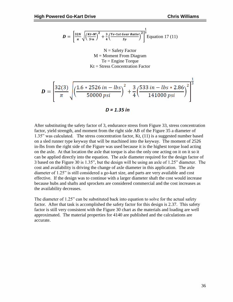
Equation 17 (11)
N = Safety Factor
M = Moment From Diagram
Te = Engine Torque
Kt = Stress Concentration Factor
After substituting the safety factor of 3, endurance stress from Figure 33, stress concentration
factor, yield strength, and moment from the right side AB of the Figure 35 a diameter of
1.35” was calculated. The stress concentration factor, Kt, (11) is a suggested number based
on a sled runner type keyway that will be machined into the keyway. The moment of 2526
in-lbs from the right side of the Figure was used because it is the highest torque load acting
on the axle. At that location the axle that torque is also the only one acting on it on it so it
can be applied directly into the equation. The axle diameter required for the design factor of
3 based on the Figure 30 is 1.35”, but the design will be using an axle of 1.25” diameter. The
cost and availability is driving the change of axle diameter in this application. The axle
diameter of 1.25” is still considered a go-kart size, and parts are very available and cost
effective. If the design was to continue with a larger diameter shaft the cost would increase
because hubs and shafts and sprockets are considered commercial and the cost increases as
the availability decreases.
The diameter of 1.25” can be substituted back into equation to solve for the actual safety
factor. After that task is accomplished the safety factor for this design is 2.37. This safety
factor is still very consistent with the Figure 30 chart as the materials and loading are well
approximated. The material properties for 4140 are published and the calculations are
accurate.

High Powered Go-Kart Drive Chris Williams
37
JACK SHAFT ASSEMBLY
The ¾” jack shaft was initially sized based on go-kart standard jack shaft components, then
using the equations below the sized was validated to be adequate for the design. As in the
axle design the jack shaft stress analysis the first step is to calculate the polar moment of
inertia which is shown earlier in Equation 13. The polar moment of inertia calculated for the
jackshaft is .03. The next step is to calculate the torsional shear shown in Equation 16; the
difference between Equations 14 and 16 is the final gear ration is not applied to the jack
shaft. Instead the 1st gear ratio from the engine is applied. The 1
st gear ratio in comparison
to any other is the 1st provides the most torque applied to the shaft. This torque stresses the
shaft more than any other gear ratio. The torsional shear applied to the jack shaft from the
engine is 55, 215 psi including a safety factor, N, of 3. The shaft is well below the ultimate
strength of 90,600 psi since the shaft specified to be made from 1045 cold drawn steel.
( ( ) ) ) Equation 18 (11)
The design of the jackshaft configuration allows for some assumptions to be made which
allows for the neglect of the moment analysis as in the axle section. The reason for this
neglect is that the shaft is much shorter and the bearings are placed immediately adjacent to
the loaded sprockets. This removes the need to account for bending moments. The shear
stress on the jackshaft is analyzed through Equation 19 below, to prove that the shaft is not
being over stressed. The shear stress of 8282 psi is still well below the capabilities of the
material so it will work with the design.
Equation 19 (11)
N = Safety Factor

High Powered Go-Kart Drive Chris Williams
38
The bolts used to attach the jack shaft assembly to the frame need to also be analyzed to
ensure they will not be sheared off by the pulling force of the chain. Solving for the shear
stress on the bolts requires the shear area of the bolt, the number of bolts, the factor of safety
and the force applied to the bolts. According to the design there are 4-3/8” bolts holding the
assembly in place that have a shear area of .10in^2, as mentioned earlier the factor of safety
is 3, and the force comes from the chain, Fc, in Equation 16. Since stress is F/A the shear on
the bolts is calculated to be 8,776psi per bolt. This shear stress requires the bolts to be grade
8 qualities, which are rated to a shear stress of 9,939psi. The area has to be multiplied by the
number of bolts to account for the stress applied to each bolt. This information is taken from
manufacturers data see Figure 36 below.
Figure 36 – Bolt Shear (15)

High Powered Go-Kart Drive Chris Williams
39
REVERSE ELECTRIC MOTOR REQUIREMENTS
When calculating the forces required to move a vehicle, the forces that resist the vehicle from
moving need to be identified. These forces are rolling resistance, air resistance, and gravity
as the vehicle encounters and incline. These forces have several constants that need to be
accounted for when calculating them. These constants can be seen in Table 4, some of the
constants are assumed based on the recommendations from another example posted online
(21). The weight of the vehicle is 400lbs. The frontal area of the car is just estimated and an
assumption of 1sq. ft. is used because the kart is mostly steel tubing, with no paneling. The
incline is estimated of 2 percent grade, based on knowledge of where the vehicle will be
operated. The design intent is to move at a max speed of 10mph, or 14.7 ft/s.
Table 6 – Force Constants
The vehicle rolling resistance can be calculated by Equation 20 as seen below.
( ) ( )
Equation 20
Froll = 400lbs * (.003 + .015) = 7lbs
The force created by the incline can be calculated with Equation 21.
( ) (
) Equation 21
Finc = 400lbs * (2/100) = 8lbs
High Powered Go-Kart Drive Chris Williams
40
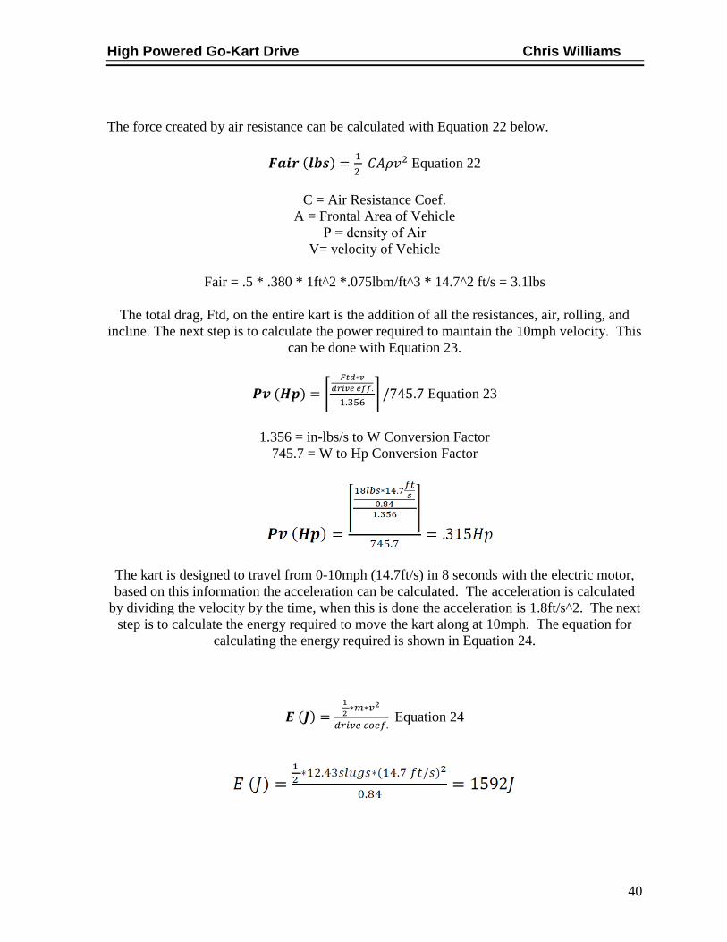
The force created by air resistance can be calculated with Equation 22 below.
( )
Equation 22
C = Air Resistance Coef.
A = Frontal Area of Vehicle
Ρ = density of Air
V= velocity of Vehicle
Fair = .5 * .380 * 1ft^2 *.075lbm/ft^3 * 14.7^2 ft/s = 3.1lbs
The total drag, Ftd, on the entire kart is the addition of all the resistances, air, rolling, and
incline. The next step is to calculate the power required to maintain the 10mph velocity. This
can be done with Equation 23.
( ) [
] Equation 23
1.356 = in-lbs/s to W Conversion Factor
745.7 = W to Hp Conversion Factor
The kart is designed to travel from 0-10mph (14.7ft/s) in 8 seconds with the electric motor,
based on this information the acceleration can be calculated. The acceleration is calculated
by dividing the velocity by the time, when this is done the acceleration is 1.8ft/s^2. The next
step is to calculate the energy required to move the kart along at 10mph. The equation for
calculating the energy required is shown in Equation 24.
( )
Equation 24

High Powered Go-Kart Drive Chris Williams
41
The energy can be converted to power by dividing the energy to get to speed by the time to
achieve 10mph as shown in Equation 25. The power in watts, W, can be converted to
horsepower, Hp, by dividing watts by 745.7 as 1Hp = 745.7W. After doing this the power
required to accelerate the kart to 10mph in 8sec is .27Hp.
Equation 25
The total power required to move the kart is the addition of the power to maintain velocity,
Pv, and the power to accelerate, Pa. When combined Pv + Pa = .58Hp. The motor specified
from Ampflow.com should provide at least 1.9 Hp at 12Vdc. This is a 3.3 design factor of
safety. The next step to selecting verifying the motor will work is determining the torque
required to move the cart is less than the stall torque of the motor. The Ampflow motor
selected has a stall torque of 3840 oz-in when supplied with 24Vdc, as directed by the
manufacture when the voltage is decreased to 12Vdc the torque is also decreased by half to
1920 oz-in. This converts to 120 lb-in. The torque required is first determined by the
addition of the rolling force required, Froll, and incline force required, Finc. The air
resistance is neglected because velocity is zero when kart is leaving from rest. After adding
the two forces that resultant must be multiplied by the tire radius, r, because T=F * r, the
torque is then divided by the gear ratio. The complete equation for required torque is shown
below in Equation 26. The motor selected is sufficient for the design because it is 5.6 times
less than the stall torque when the motor is operated at 12Vdc. The manufacturer’s motor
specifications are located in Figure 37 (21).
( )
( )
Equation 26

High Powered Go-Kart Drive Chris Williams
42
Figure 37 – AMPFLOW A40-300 Motor Specifications (10)

High Powered Go-Kart Drive Chris Williams
43
FABRICATION & TESTING
FABRICATION
This build required several different processes to complete the final product. These processes
ranged from non-skill intensive such as grinding to high skill intensive such as CNC
machining processes. The frame support braces had to be welded in as shown in figure 23
above. The most technical machining processes used was Electric Discharge Machining
(EDM), this process was used to cut internal splines on the starter shaft. These splines shown
in Figure 38 were not a common gear and several test plates were cut using the Waterjet to
insure the proper fit. Although most there was an assembly drawing showing locations of all
the components, all of the mounting holes were drilled after a fit up. This ensured everything
was running true and had good alignment as the frame was not welded with a jig the
assembly fit had to be verified. The first stages of the mock up and measurements can be
seen in Figure 39. Several other machining processes were also used and those consisted of,
welding, milling, turning, pressing, drilling, cutting, and grinding.
Figure 38 – Starter Shaft Splines
Figure 39 –Mock Up

High Powered Go-Kart Drive Chris Williams
44
TESTING, RESULTS, AND CHANGES
The testing on this bike was being completed simultaneously with the fabrication process.
This means as the build progressed each component was tested. This helped to ensure that
after parts were complete they would work. This method proved to be quite the case with the
electric starter. The electric starter had to deviate from the original design multiple times.
After testing the starter there was a lot of information to be gained and resulted in several
changes. The biggest revelation to testing the starter was realizing it was not going to work.
This partly came from learning that the GM starter shown in Figure 27 is advertised as
having 250ft-lb of torque, but in that is only when used with the flywheel in the car. The
actual torque rating of starter motor alone is 20ft-lb. This is the reason there were several
different phases made in the drive of the starter. The sprocket configuration had to change
several times. The sprocket configuration shown in Figure-40 is when the next design flaw
was realized, this is also the point in the design where the most torque was transmitted to the
starter input shaft of the motor. When all the extra torque was going through the system it
eventually locked up, and had to be disassembled. After inspection it was realized that the
bronze bushings that the shafts were spinning in were partly the culprit for the need of extra
torque. There was too much loading between the shafts and the bushings, causing them to
bind.
Figure 40 – Starter High-Torque
These bushings had to be replaced with needle bearings to accommodate the loading and
allow the shafts to still spin. After these bearings were installed the starter was able to work
much better. In fact the gearing was able to be able to reduced to 2.8:1. This can be seen in
figure 41 below.

High Powered Go-Kart Drive Chris Williams
45
Figure 41 – Final Starter Configuration
During testing the reverse was also modified from the original design. The reverse worked
well on flat smooth ground, after more extensive testing in mud and different inclines it was
determined there needed to be some changes to the design. The reverse also moved too fast
for practical reversing. After further review the jackshaft from the starter modification was
utilized based on location and size. In figure 42 the final reverse drive is shown, with this
configuration the reverse was a practical speed and had tremendous torque. The kart could
roll up a 45 degree angle with no problems. Another major modification is the reverse motor
was wired up at 24Vdc this also provided more torque and sped up the output since the axle
speed was reduced through the jackshaft.
Figure 42 – Reverse Gearing

High Powered Go-Kart Drive Chris Williams
46
CONCLUSION
This go-kart is more powerful than most common go-karts, it also has electric start, and
reverse. This go-kart has been engineered to last for years to come. It will provide the rider
with enjoyment as it is considered High-powered and has strong performance numbers. The
go-kart has the ability to easily select gears and provide the operator the torque band they
require. Below are images to attest for the quality and strength of the design.
Figure 43 – Side View
Figure 44 – Rear Side

High Powered Go-Kart Drive Chris Williams
47
Figure 45 - Front
Figure 46 - Rear

High Powered Go-Kart Drive Chris Williams
48
WORKS CITED 1. Old Minibikes. [Online] [Cited: September 13, 2012.]
http://www.oldminibikes.com/forum/more-than-two-wheels/1504-my-gocart-build-3.html.
2. Country Go Karts. [Online] [Cited: September 12, 2012.]
http://www.countrygocarts.com/american-sportworks-zircon-off-road-go-kart/.
3. Hammer Head Offroad. [Online] [Cited: September 11, 2012.]
http://www.hammerheadoffroad.com/product_details.php?sub_id=19&main_cat_id=6&name
=GTS%20250#Specification.
4. MX Motorsports. [Online] [Cited: September 11, 2012.]
http://www.mxmotorsports.us/BMS-Dune-Buggy-400-Sand-Sniper-CA-Appoved-p/bms-
dune buggy 400 sand sniper.htm.
5. Jr., Mike Harris. Mr. Hamilton, OH, September 05, 2012.
6. House, Jason. Mr. Hamilton, OH, September 12, 2012.
7. Davish, Derek. Mr. Hamilton, OH, September 08, 2012.
8. Taveras, Erickson. Mr. Hamilton, OH, August 30, 2012.
9. Mini Buggy FNR. Stak 4x4. [Online] STaK Up Marketing Company, 2005. [Cited:
October 17, 2012.] http://www.stak4x4.com/mini_buggy_fnr.htm.
10. gettosled. RPM FNR Gearbox Mounting Fix: zx10 Rhino. s.l. : MinniBuggy.Net, March
3, 2012.
11. 218390A - Forward / Reverse Gearbox. MFG SUPPLY. [Online] MFG SUPPLY, 1995-
2012. [Cited: November 9, 2011.]
http://www.mfgsupply.com/gomini/gominiaxles/gominiaxlesgearbox/218390a.html.
12. Baboon. EdgeBuggyForums.com. April 26, 2008.
13. Powell, J.C. YZ490 Kick Start Return Spring. WeeksMotorcycle.com. [Online] J.C.
Powell Weeks Motorcycle Salvage, 2009-2011. [Cited: November 11, 2012.]
http://www.weeksmotorcycle.com/yz490-kick-start.html .
14. Starters, Chrome. RaceCar Performance Supply. [Online] 2012. [Cited: December 14,
2012.]
http://racecarperformancesupply.com/index.php?cPath=2_29&osCsid=37913b7de8c4faa2e9
b7f2cad67c9a23.
15. Brake Calculations. Engineeering Inspiration. [Online] 2012. [Cited: December 18,
2012.] http://www.engineeringinspiration.co.uk/brakecalcs.html.
16. Mott, Robert L. Machine Elements in Mechanical Design. s.l. : Pearson Prentice Hall,
2004. 0-13-061885-3.
17. R.G. Mortimer, L. Segel, H. Dugoff, J.D. Campbell, C.M. Jorgeson, R.W. Murphy.
Brake Force Requirement Study. Washington, D.C. : Department of Transportation, 1970.
HSRI Report No. HuF-6a.
18. Ruiz, Steve. Brake Pedal Setup and Dual Master Cylinder Installation Guide.
[Installation Guide] s.l. : Stop Tech LLC, 2005.
19. Chris Longhurst. The Brake Bible. CarBibles.com. [Online] 1994-2012. [Cited:
December 12, 2012.] http://www.carbibles.com/brake_bible.html.
20. Sheer Strength. www.nucor-fastener.com. [Online] [Cited: January 13, 2013.] nucor-
fastener.com/Files/PDFs/.../TDS_013_Shear_Strength.pdf.
21. Cameron Motor Works Electric Vehicle Conversion. Calculate Motor Size. [Online]
High Powered Go-Kart Drive Chris Williams
49
Cameron Software Ltd., 2004-2005. [Cited: October 20, 2012.]
http://www.cameronsoftware.com/ev/EV_CalculateMotorSize.html .
22. Ampflow. Ampflow.com. [Online] [Cited: October 29, 2012.]
http://ampflow.com/ampflow_motors.htm.
23. Automotive Power. Cameron Motor Works Electric Vehicle Conversion. [Online] 2004-
2005. [Cited: October 20, 2012.]
http://wps.aw.com/wps/media/objects/877/898586/topics/topic02.pdf.

Appendix A1
APPENDIX A RESEARCH
Interview with avid motorsports enthusiast: Mike Harris Jr. 1457 Missy Court,
Hamilton, OH 45013 09/05/12
He has 15+ years of experience with dirt bikes and off road motorsports
applications. Mechanical engineering, 5+ years in machine design experience.
He felt that my project seemed to be challenging. Some problem areas to
acknowledge would be reliable accurate ways to shift the engine. He
recommended some kind of strong cable or hard linkage. Another area he
thought could lead to issues is hard to kick start inside the roll cage. He
thought the engine I currently use would have an extreme amount of power,
and suggested I make sure that power and torque could be supported at the
shaft.
He also suggested I look into possibly a different engine with electric start and
reverse.
Important features to include: Easy Starting, Reliable Shifting, Strong Shaft
and Drive Components, Reverse.
Interview with fellow Mechanical Engineering Student: Erickson Taveras 3810
Putnam Ave, Hamilton OH 45015 08/30/12
He has 3 years design experience and enjoys performance vehicles.
He thought my project seemed to be very exciting. He said I was creating
something with lots more power than what is available commercially. He liked
that I was trying to blend the high powered engine with the preexisting frame.
He also likes the potential to be able to shift it to select gears and power bands.
After discussing the original design, he thought that I needed to focus on
repairs and maintenance.
Important features to include: Easy to Maintain, Easy to Repair, Shiftable,
Affordable Design Components

Appendix A2
Interview with friend: Derek Davish 5622 West Elkton rd. Somerville, OH
45064 3810 09/08/12
He has 15+ years with riding ATV’s, building racecars, and driving race cars.
He had some friends try to do the same thing on a smaller scale with a little
frame and less powerful engine. He said they had troubles configuring the
shift linkage and converting the gas cable to extend to a functioning location.
He said they ultimately ended up bailing on the project. He did notice that the
braking system on my kart needed to hold better. There was not enough
braking power to slow the kart down as quickly as it should. He also was
stating the clutch would have to work well in order to keep from blowing up
the transmission gears.
Important features to include: Easy to Shift, Durable and Reliable Linkages,
Easy Clutch Operation.
Interview with friend: Jason House 851 Clinton Ave. Hamilton, OH 45013
09/12/12
He has 12+ design experience and is currently a designer for GE aviation.
He noticed I did not have a proper air cleaner on my cart and was worried that
it may not keep the fuel delivery system clean and functional. He liked the
concept and was curious on what kind of brakes would work best. He
recommended disk brakes and said that there are many manufactures where I
could by them stock versus making a custom application. He also noticed an
engine mount that was not being secured and recommended with the
horsepower that this motor has to fully secure the engine. He liked the clutch
being in a pedal versus a hand lever. He said it made it more like a car and
seemed to be a more consistent and solid design.
Important features to include: Standard Parts, Disk Brakes, Functional Air
Cleaner for Engine Reliability, Secure Engine Mount, Pedal Actuated Clutch,
Safety

Appendix A3
Jeep 2003 Oldminibikes Forum Go Kart
The Jeep 2003 go kart uses a 175cc 2 stroke Yamaha dirt bike
engine. He uses band brakes and hard cables to actuate the gas
and brakes. He has a hard linkage to actuate the shifter arm. He
also uses a chain, sprocket, and jackshaft set up to actuate the kick
starter shaft on the engine case.
Specifications:
175cc 2 stroke Yahama Dirt bike Engine
Band Brakes
Basic Cable Linkage setup for clutch, gas, and brakes
Hard linkage
Jack Shaft Kick Start Mechanism
1.) Band brakes will
be too weak and
not reliable.
2.) Disc brakes
would be more
reliable option.
3.) The shifter
linkage may be
problematic with
being able to
maintain proper
alignments and
wear out over
time.
http://www.oldminibike
s.com/forum/more-than-
two-wheels/1504-my-
gocart-build-3.html
09/13/12

Appendix A4
American Sportworks Zircon Off-Road Go Kart
This go-kart designed for two uses a 150cc 4 stroke engine and
dual belt driven torque converters. The cart is automatic and does
not require any clutch actuation or gear selection.
Secifications:
150cc 4 stroke Engine
Dual Torque Converters
Automatic
1.) Engine has less
than half the
power.
2.) Using a 4 stroke
motor will not
deliver the same
torque as a 2
stroke motor.
3.) The automatic
feature does not
allow the
operator to select
the power band
and speed range.
4.) The belts have
the potential to
wear out and slip
which loses
power and ads to
maintenance
costs.
Hammer Head Off-Road GTS 250 Go-Kart
This go-kart designed for two uses a 250cc liquid cooled engine.
The cart is automatic with gear selections of high low and reverse.
This cart also has front and rear hydraulic disc brakes.
Secifications:
250cc Liquid Cooled Engine
High Low Reverse
Front and Rear Disc Brakes
1.) This engine has half
the power of
potential design.
2.) It has 2 selectable
speeds.
3.) Reverse is available
which increases
maneuverability.
http://www.countrygoca
rts.com/american-
sportworks-zircon-off-
road-go-kart/
09/11/12
http://www.hammerhea
doffroad.com/product_d
etails.php?sub_id=19&
main_cat_id=6&name=
GTS%20250#Specificat
ion 09/11/12

Appendix A5
BMS Dune Buggy 400 Sand Sniper
This go-kart designed for two uses a 399cc liquid cooled engine.
The cart is automatic with 5 gear selections which includes
reverse. This cart also has front and rear hydraulic disc brakes and
is shaft driven
Secifications:
399cc 4-Stoke Liquid Cooled Engine
5 Speed Transmission including Reverse
Front and Rear Disc Brakes
Shaft Driven
1.) This engine does
not have the
power of
potential design.
2.) The shaft driven
system may
prove to be a
costly option for
repairs.
3.) The machine
also has disc
brakes.
http://www.mxmotorspo
rts.us/BMS-Dune-
Buggy-400-Sand-
Sniper-CA-Appoved-
p/bms-
dune%20buggy%20400
%20sand%20sniper.htm
09/11/12
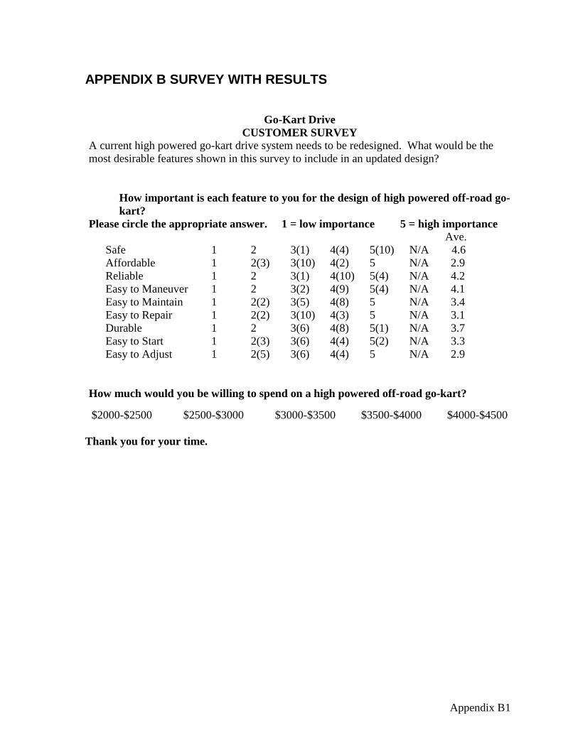
Appendix B1
APPENDIX B SURVEY WITH RESULTS
Go-Kart Drive
CUSTOMER SURVEY
A current high powered go-kart drive system needs to be redesigned. What would be the
most desirable features shown in this survey to include in an updated design?
How important is each feature to you for the design of high powered off-road go-
kart?
Please circle the appropriate answer. 1 = low importance 5 = high importance Ave.
Safe 1 2 3(1) 4(4) 5(10) N/A 4.6
Affordable 1 2(3) 3(10) 4(2) 5 N/A 2.9
Reliable 1 2 3(1) 4(10) 5(4) N/A 4.2
Easy to Maneuver 1 2 3(2) 4(9) 5(4) N/A 4.1
Easy to Maintain 1 2(2) 3(5) 4(8) 5 N/A 3.4
Easy to Repair 1 2(2) 3(10) 4(3) 5 N/A 3.1
Durable 1 2 3(6) 4(8) 5(1) N/A 3.7
Easy to Start 1 2(3) 3(6) 4(4) 5(2) N/A 3.3
Easy to Adjust 1 2(5) 3(6) 4(4) 5 N/A 2.9
How much would you be willing to spend on a high powered off-road go-kart?
$2000-$2500 $2500-$3000 $3000-$3500 $3500-$4000 $4000-$4500
Thank you for your time.

Appendix C1
APPENDIX C QFD

Appendix D1
APPENDIX D PRODUCT OBJECTIVES
Objectives This list of product objectives provides a firmer definition of the needs of the customer. The
objectives listed below helps the designer to insure those needs are met through the proper use of
engineering characteristics.
10. Safe 18%
a. Chain guards
b. Pinch Point Guards
c. Design for forces and select proper components for adequate braking.
11. Easy to Maneuver 15%
a. Design reversing gear to allow for tight quarter maneuvering.
b. Foot Controls for clutch to keep hands free for driving and operating shifter.
c. Hand Shift Lever-ergonomically located for comfortable gear selection.
12. Reliable 13%
a. Reliable measured by component life and proper design criteria in the
following specs.
i. Bearings
ii. Sprockets
iii. Chain
iv. Shafts
13. Durable 11%
a. Determine a design factor to use in calculations to prevent failures.
b. Rust-resistant material selection
c. Adequately size purchased components based on force/loading calculations in
conjunction with safety factor to prevent part failure.
14. Easy to Maintain 10%
a. Through proper component selection by designing for long lifetimes the
machine maintenance time is kept at a minimum of 30 minutes or less per
service.
15. Easy to Repair 9%
a. Design for reduced time in disassembly for reduced repair times.
b. Design using standard components for fast part turn around in the event of a
failed or worn part. It shall be quick to replace.
16. Easy to Start 8%
a. Design the incorporation if engine allows for incorporation of electric starter.
b. If the engine doesn’t allow for the incorporation of electric starter design for
an easy to use starting lever.
17. Cost 8%
a. Total design and build cost less than $2000
18. Easy to Adjust 8%
a. Components
b. Access
c. Tensioners

Appendix E1
APPENDIX E SCHEDULE

Appendix F1
APPENDIX F BUDGET

Appendix G1
APPENDIX G DETAIL DRAWINGS

Appendix G2

Appendix G3

Appendix G4

Appendix G5

Appendix G6

Appendix G7

Appendix G8

Appendix G9

Appendix G10

Appendix G11

Appendix G12

Appendix G13

Appendix G14

Appendix G15

Appendix G16

Appendix H1
APPENDIX H SPREAD SHEETS

Appendix H2

Appendix H3

Appendix H4

Appendix H5

Appendix H6

Appendix H7