Embed Size (px)
Citation preview
High pressure drop-tube pyrolysis of brown coal and its kinetics
Kevin Günther, Steffen Krzack, Jörg Kleeberg, Bernd MeyerInstitute of Energy Process Engineering and Chemical Engineering (IEC) / Virtuhcon – Virtual High Temperature conversionTU Bergakademie Freiberg
Berlin, Germany5th June 2018
Center for Innovation Competence:Virtual High Temperature Conversion
High pressure drop-tube pyrolysis
Outline
2
I. Motivation
II. Feedstock characterization
III. Drop-tube reactor and process balancing
IV. Product yields
V. Reaction kinetics
VI. Summary and outlook
High pressure drop-tube pyrolysis
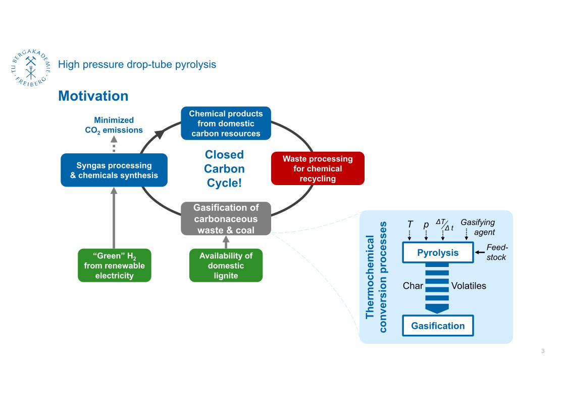
Motivation
3
Waste processing for chemical
recycling
Availability of domestic
lignite
“Green” H2from renewable
electricity
Gasification of carbonaceous waste & coal
Chemical products from domestic
carbon resources
ClosedCarbon Cycle!
Minimized CO2 emissions
Syngas processing& chemicals synthesis
Gasification
Pyrolysis
VolatilesChar
Feed-stock
T p ΔTΔ t
Gasifyingagent
Ther
moc
hem
ical
conv
ersi
onpr
oces
ses
High pressure drop-tube pyrolysis – Feedstock
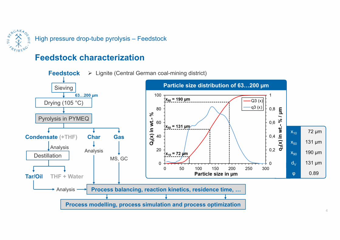
Feedstock characterization
4
Drying (105 °C)
Sieving
Pyrolysis in PYMEQ
CharCondensate (+THF) Gas
Tar/Oil
Destillation
THF + Water
Analysis
Analysis
MS, GC
Analysis
63…200 µm
Process balancing, reaction kinetics, residence time, …
Process modelling, process simulation and process optimization
Lignite (Central German coal-mining district)Feedstock
x10 72 µm
x50 131 µm
x90 190 µm
dV 131 µm
φ 0.89
Particle size distribution of 63…200 µm
High pressure drop-tube pyrolysis – Drop-tube reactor
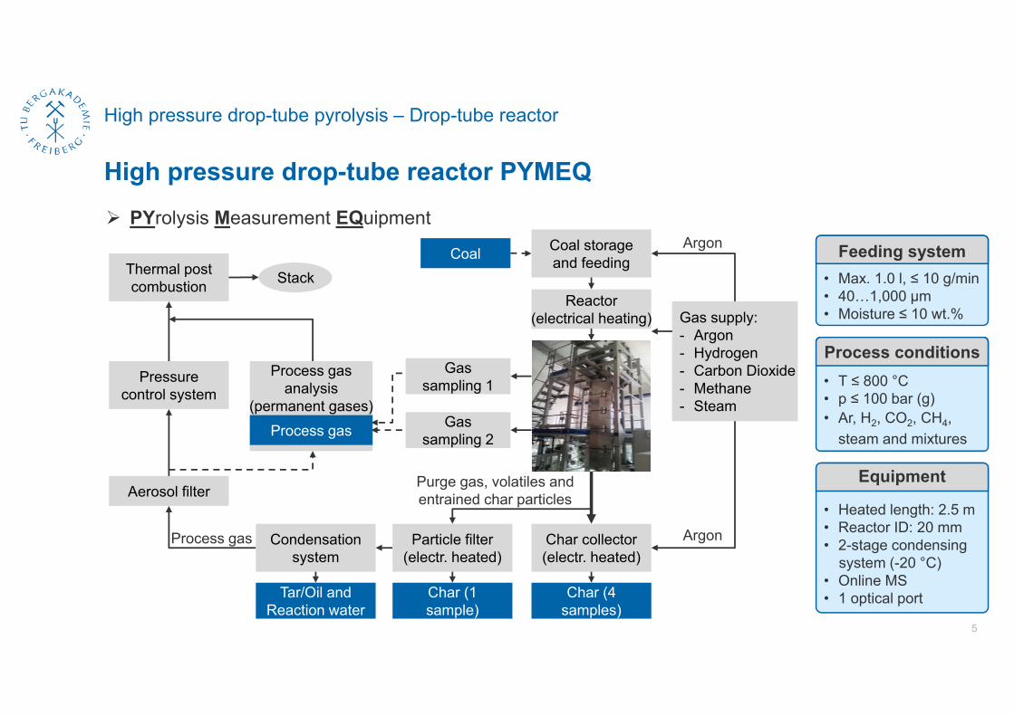
High pressure drop-tube reactor PYMEQ
5
PYrolysis Measurement EQuipment
Gas supply:- Argon- Hydrogen- Carbon Dioxide- Methane- Steam
Argon
Argon
Pressure control system
Process gasanalysis
(permanent gases)
Thermal post combustion
Process gas
Stack
Gas sampling 1
Gas sampling 2
Char collector(electr. heated)
Char (4 samples)
Particle filter(electr. heated)
Condensationsystem
Purge gas, volatiles andentrained char particles
Char (1 sample)
Tar/Oil andReaction water
Process gas
Aerosol filter
Coal storage and feedingCoal
Reactor(electrical heating)
• T ≤ 800 °C• p ≤ 100 bar (g)• Ar, H2, CO2, CH4,
steam and mixtures
Process conditions
• Heated length: 2.5 m• Reactor ID: 20 mm• 2-stage condensing
system (-20 °C)• Online MS• 1 optical port
Feeding system• Max. 1.0 l, ≤ 10 g/min• 40…1,000 µm• Moisture ≤ 10 wt.%
Equipment
600 °C 700 °C 800 °C5 bar x
10 bar x
20 bar x x x
40 bar x x x
80 bar x x x
100 bar x
High pressure drop-tube pyrolysis – Characterization methods
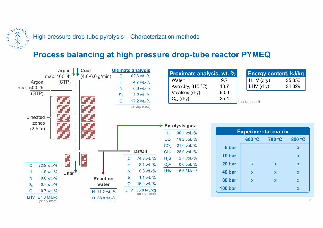
Process balancing at high pressure drop-tube reactor PYMEQ
6
C 62.6 wt.-%H 4.7 wt.-%N 0.6 wt.-%SC 1.2 wt.-%O 17.2 wt.-%
Coal(4.8-6.0 g/min)
Char
Argonmax. 500 l/h
(STP)
5 heatedzones
(2.5 m)
Argonmax. 100 l/h
(STP)
Pyrolysis gas
Tar/Oil
Reactionwater
C 72.9 wt.-%H 1.8 wt.-%N 0.6 wt.-%SC 0.7 wt.-%O 0.7 wt.-%
LHV 27.0 MJ/kg
H2 30.1 vol.-%CO 18.2 vol.-%CO2 21.0 vol.-%CH4 28.0 vol.-%H2S 2.1 vol.-%C2+ 0.6 vol.-%LHV 16.5 MJ/m³
Experimental matrix
H 11.2 wt.-%O 88.8 wt.-%
*as received
Water* 9.7Ash (dry, 815 °C) 13.7Volatiles (dry) 50.9Cfix (dry) 35.4
Proximate analysis, wt.-%Ultimate analysis Energy content, kJ/kgHHV (dry) 25,350LHV (dry) 24,329
C 74.3 wt.-%H 8.1 wt.-%N 0.3 wt.-%S 1.1 wt.-%O 16.2 wt.-%
LHV 33.8 MJ/kg
(at dry state)
(at dry state)
(at dry state)
High pressure drop-tube pyrolysis – Results of pyrolysis investigations
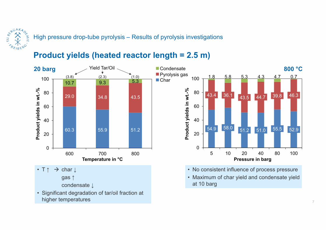
Product yields (heated reactor length = 2.5 m)
7
54,9 58,0 51,2 51,0 55,5 52,9
43,4 36,1 43,5 44,7 39,8 46,3
0
20
40
60
80
100
5 10 20 40 80 100
Prod
uct y
ield
s in
wt.-
%
Pressure in barg
60,3 55,9 51,2
29,0 34,8 43,5
10,7 9,3 5,3
0
20
40
60
80
100
600 700 800
Prod
uct y
ield
s in
wt.-
%
Temperature in °C
5.3 0.75.81.8 4.74.3(1.0)(2.3)(3.8)
Yield Tar/Oil
• T ↑ char ↓gas ↑condensate ↓
• Significant degradation of tar/oil fraction athigher temperatures
• No consistent influence of process pressure• Maximum of char yield and condensate yield
at 10 barg
20 barg 800 °CCondensatePyrolysis gasChar
60.3 55.9 51.2 54.9 58.0 51.2 51.0 55.5 52.9
43.4 36.1 43.5 44.7 39.8 46.329.0 34.8 43.5
10.7 9.3 5.3
High pressure drop-tube pyrolysis – Reaction kinetics (model)
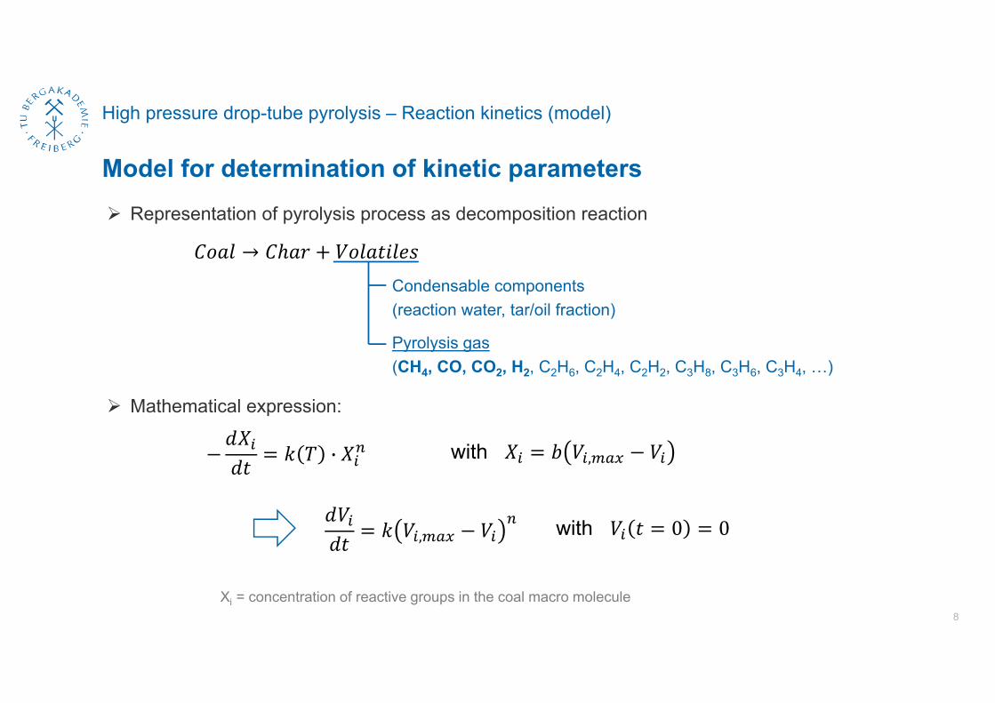
Model for determination of kinetic parameters
8
Representation of pyrolysis process as decomposition reaction
→
· with ,
Xi = concentration of reactive groups in the coal macro molecule
Condensable components(reaction water, tar/oil fraction)
Pyrolysis gas(CH4, CO, CO2, H2, C2H6, C2H4, C2H2, C3H8, C3H6, C3H4, …)
, with 0 0
Mathematical expression:
High pressure drop-tube pyrolysis – Reaction kinetics (model)
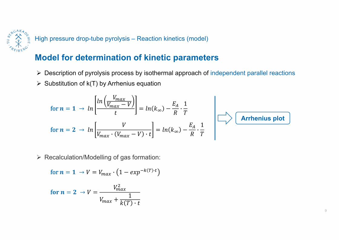
Model for determination of kinetic parameters
9
for → ·1
for → · · ·1
Description of pyrolysis process by isothermal approach of independent parallel reactions
Arrhenius plot
for → · 1 ·
f → 1·
Recalculation/Modelling of gas formation:
Substitution of k(T) by Arrhenius equation
High pressure drop-tube pyrolysis – Reaction kinetics (kinetic parameters)
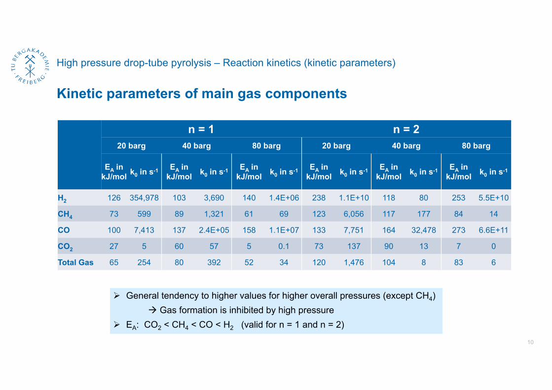
Kinetic parameters of main gas components
10
n = 1 n = 220 barg 40 barg 80 barg 20 barg 40 barg 80 barg
EA in kJ/mol k0 in s-1 EA in
kJ/mol k0 in s-1 EA in kJ/mol k0 in s-1 EA in
kJ/mol k0 in s-1 EA in kJ/mol k0 in s-1 EA in
kJ/mol k0 in s-1
H2 126 354,978 103 3,690 140 1.4E+06 238 1.1E+10 118 80 253 5.5E+10
CH4 73 599 89 1,321 61 69 123 6,056 117 177 84 14
CO 100 7,413 137 2.4E+05 158 1.1E+07 133 7,751 164 32,478 273 6.6E+11
CO2 27 5 60 57 5 0.1 73 137 90 13 7 0
Total Gas 65 254 80 392 52 34 120 1,476 104 8 83 6
General tendency to higher values for higher overall pressures (except CH4) Gas formation is inhibited by high pressure
EA: CO2 < CH4 < CO < H2 (valid for n = 1 and n = 2)
High pressure drop-tube pyrolysis – Reaction kinetics (modelling of gas formation)
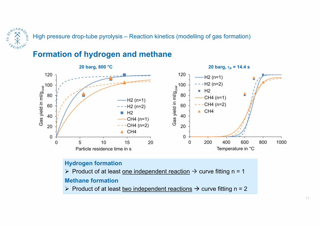
Formation of hydrogen and methane
11
20 barg, 800 °C
Hydrogen formation Product of at least one independent reaction curve fitting n = 1Methane formation Product of at least two independent reactions curve fitting n = 2
0
20
40
60
80
100
120
0 200 400 600 800 1000
Gas
yie
ld in
ml/g
coal
Temperature in °C
H2 (n=1)H2 (n=2)H2CH4 (n=1)CH4 (n=2)CH4
20 barg, P = 14.4 s
0
20
40
60
80
100
120
0 5 10 15 20
Gas
yie
ld in
ml/g
coal
Particle residence time in s
H2 (n=1)H2 (n=2)H2CH4 (n=1)CH4 (n=2)CH4
High pressure drop-tube pyrolysis – Reaction kinetics (modelling of gas formation)
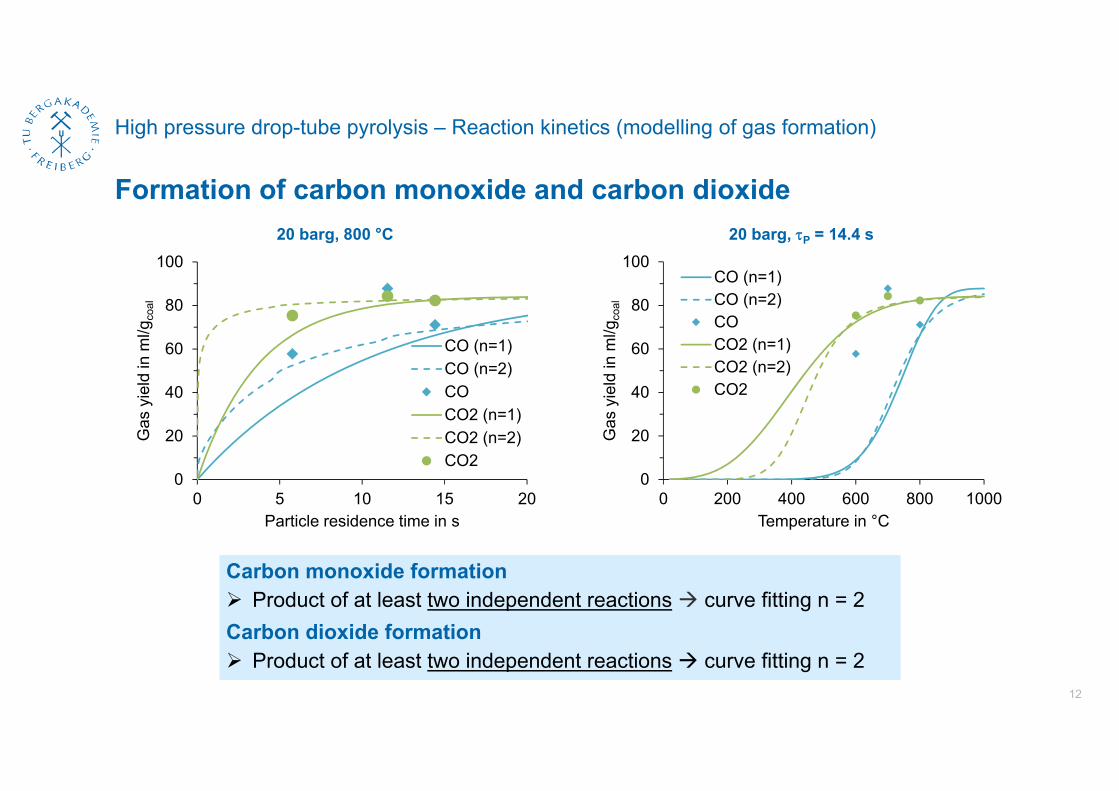
Formation of carbon monoxide and carbon dioxide
12
0
20
40
60
80
100
0 5 10 15 20
Gas
yie
ld in
ml/g
coal
Particle residence time in s
CO (n=1)CO (n=2)COCO2 (n=1)CO2 (n=2)CO2
Carbon monoxide formation Product of at least two independent reactions curve fitting n = 2Carbon dioxide formation Product of at least two independent reactions curve fitting n = 2
20 barg, 800 °C
0
20
40
60
80
100
0 200 400 600 800 1000
Gas
yie
ld in
ml/g
coal
Temperature in °C
CO (n=1)CO (n=2)COCO2 (n=1)CO2 (n=2)CO2
20 barg, P = 14.4 s
High pressure drop-tube pyrolysis
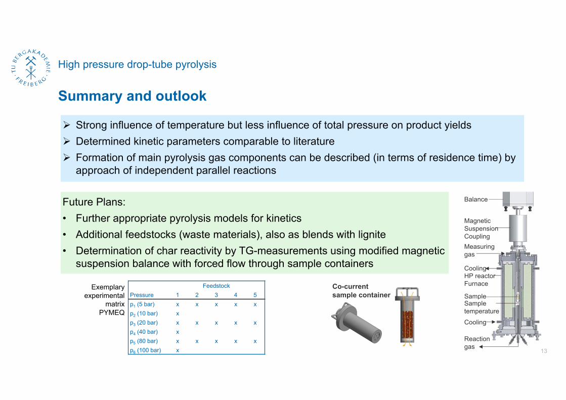
Summary and outlook
13
FeedstockPressure 1 2 3 4 5p1 (5 bar) x x x x xp2 (10 bar) xp3 (20 bar) x x x x xp4 (40 bar) xp5 (80 bar) x x x x xp6 (100 bar) x
Exemplaryexperimental
matrixPYMEQ
Strong influence of temperature but less influence of total pressure on product yields Determined kinetic parameters comparable to literature Formation of main pyrolysis gas components can be described (in terms of residence time) by
approach of independent parallel reactions
Future Plans:• Further appropriate pyrolysis models for kinetics• Additional feedstocks (waste materials), also as blends with lignite• Determination of char reactivity by TG-measurements using modified magnetic
suspension balance with forced flow through sample containers
Balance
MagneticSuspensionCouplingMeasuringgas
Cooling
Furnace
Cooling
HP reactor
Reactiongas
SampleSampletemperature
Co-currentsample container

Thanks for your attention!
14
We gratefully acknowledge the German Federal Ministry of Education and Research (BMBF)that funded the research within the framework of the Centre for Innovation Competence Virtuhcon.


![[Doi 10.1002%2F9783527628148.Hoc063] Lackner, Maximilian; Winter, Franz; Agarwal, Avinash K. -- Handbook of Combustion (Online) Gasification and Pyrolysis of Coal](https://img.pdfslide.net/doc/110x75/55cf85d7550346484b91e4d3/doi-1010022f9783527628148hoc063-lackner-maximilian-winter-franz-agarwal.jpg)
![COAL PYROLYSIS DISTRIBUTION - COnnecting … · Master of Science in Mathematics. ... molecular structure of coal is also discussed by Van Krevelen [6], Dryden [7] ... The technology](https://img.pdfslide.net/doc/110x75/5ac973737f8b9a40728d90bf/coal-pyrolysis-distribution-connecting-of-science-in-mathematics-molecular.jpg)