Embed Size (px)
Citation preview
This specification subjects to change without notice. Sep. 07. 2009
Documents No. D4167407A
High-Resolution CCD B/W Camera
CleverDragon series
CSCU30BC18
CSCU30BC18-01
Specification Contents
RESTRICTION FOR USE ·····································································1
CASES FOR INDEMNITY (LIMITED WARRANTY) ···························2
NOTES ON USING THIS PRODUCT ····················································3
1. Overview ····························································································5
2. Features ······························································································5
3. Configuration ······················································································6
4. Optional parts ·····················································································6
5. Functions ····························································································7
6. Specifications ·····················································································21
7. Timing chart ·······················································································28
8. Outline drawing ·················································································30
9. Guarantee ··························································································31
10. Repair ······························································································31
This specification subjects to change without notice. Sep. 07. 2009
Documents No. D4167407A - 1 -
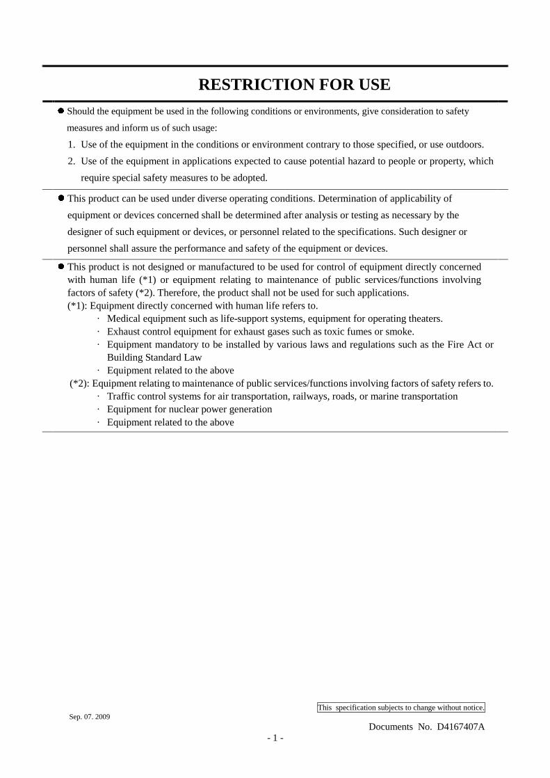
RESTRICTION FOR USE
� Should the equipment be used in the following conditions or environments, give consideration to safety
measures and inform us of such usage:
1. Use of the equipment in the conditions or environment contrary to those specified, or use outdoors.
2. Use of the equipment in applications expected to cause potential hazard to people or property, which
require special safety measures to be adopted.
� This product can be used under diverse operating conditions. Determination of applicability of
equipment or devices concerned shall be determined after analysis or testing as necessary by the
designer of such equipment or devices, or personnel related to the specifications. Such designer or
personnel shall assure the performance and safety of the equipment or devices.
� This product is not designed or manufactured to be used for control of equipment directly concerned with human life (*1) or equipment relating to maintenance of public services/functions involving factors of safety (*2). Therefore, the product shall not be used for such applications. (*1): Equipment directly concerned with human life refers to.
· Medical equipment such as life-support systems, equipment for operating theaters. · Exhaust control equipment for exhaust gases such as toxic fumes or smoke. · Equipment mandatory to be installed by various laws and regulations such as the Fire Act or
Building Standard Law · Equipment related to the above
(*2): Equipment relating to maintenance of public services/functions involving factors of safety refers to. · Traffic control systems for air transportation, railways, roads, or marine transportation · Equipment for nuclear power generation · Equipment related to the above
This specification subjects to change without notice. Sep. 07. 2009
Documents No. D4167407A - 2 -
CASES FOR INDEMNITY (LIMITED WARRANTY)
We shall be exempted from taking responsibility and held harmless for damage or losses incurred by the user
in the following cases.
� In the case damage or losses are caused by fire, earthquake, or other acts of God, acts by a third party,
deliberate or accidental misuse by the user, or use under extreme operating conditions.
� In the case of indirect, additional, consequential damages (loss of business interests, suspension of
business activities) are incurred as result of malfunction or non-function of the equipment, we shall be
exempted from responsibility for such damages.
� In the case damage or losses are caused by failure to observe the information contained in the
instructions in this instruction manual and specifications.
� In the case damage or losses are caused by use contrary to the instructions in this instruction manual and
specifications.
� In the case damage or losses are caused by malfunction or other problems resulting from use of
equipment or software that is not specified.
� In the case damage or losses are caused by repair or modification conducted by the customer or any
unauthorized third party (such as an unauthorized service representative).
� Expenses we bear on this product shall be limited to the individual price of the product.
� About the item which does not have a publication in the specifications and manual of this product, it considers
as the outside for a guarantee.
This specification subjects to change without notice. Sep. 07. 2009
Documents No. D4167407A - 3 -
NOTES ON USING THIS PRODUCT
� Handle carefully
Do not drop the equipment or allow it to be subject to strong impact or vibration, as such action may cause malfunctions. Further, do not damage the connection cable, since this may cause wire breakage.
� Environmental operating conditions
Do not use the product in locations where the ambient temperature or humidity exceeds the specifications. Otherwise, image quality may be degraded or internal components may be adversely affected. In particular, do not use the product in areas exposed to direct sunlight. Moreover, during shooting under high temperatures, vertical stripes or white spots (noise) may be produced, depending on the subject or camera conditions (such as increased gain). However, such phenomena are not malfunctions.
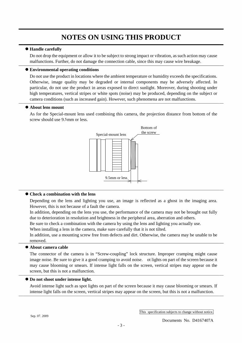
� About lens mount
As for the Special-mount lens used combining this camera, the projection distance from bottom of the screw should use 9.5mm or less.
� Check a combination with the lens
Depending on the lens and lighting you use, an image is reflected as a ghost in the imaging area. However, this is not because of a fault the camera. In addition, depending on the lens you use, the performance of the camera may not be brought out fully due to deterioration in resolution and brightness in the peripheral area, aberration and others. Be sure to check a combination with the camera by using the lens and lighting you actually use. When installing a lens in the camera, make sure carefully that it is not tilted. In addition, use a mounting screw free from defects and dirt. Otherwise, the camera may be unable to be removed.
� About camera cable
The connector of the camera is in “Screw-coupling” lock structure. Improper cramping might cause image noise. Be sure to give it a good cramping to avoid noise. ot lights on part of the screen because it may cause blooming or smears. If intense light falls on the screen, vertical stripes may appear on the screen, but this is not a malfunction.
� Do not shoot under intense light.
Avoid intense light such as spot lights on part of the screen because it may cause blooming or smears. If intense light falls on the screen, vertical stripes may appear on the screen, but this is not a malfunction.
9.5mm or less
Special-mount lens
Bottom ofthe screw
This specification subjects to change without notice. Sep. 07. 2009
Documents No. D4167407A - 4 -
� Occurrence of moiré
If you shoot thin stripe patterns, moiré patterns (interference fringes) may appear. This is not a malfunction.
� Occurrence of noise on the screen
If an intense magnetic or electromagnetic field is generated near the camera or connection cable, noise may be generated on the screen. If this occurs, move the camera or the cable.
� Handling of the protective cap
If the camera is not in use, attach the lens cap to the camera to protect the image pickup surface.
� Turn OFF the power in the case of connection
Turn OFF the power in the case of connection of connection camera cable.
Otherwise, an electric shock or a malfunction may occur.
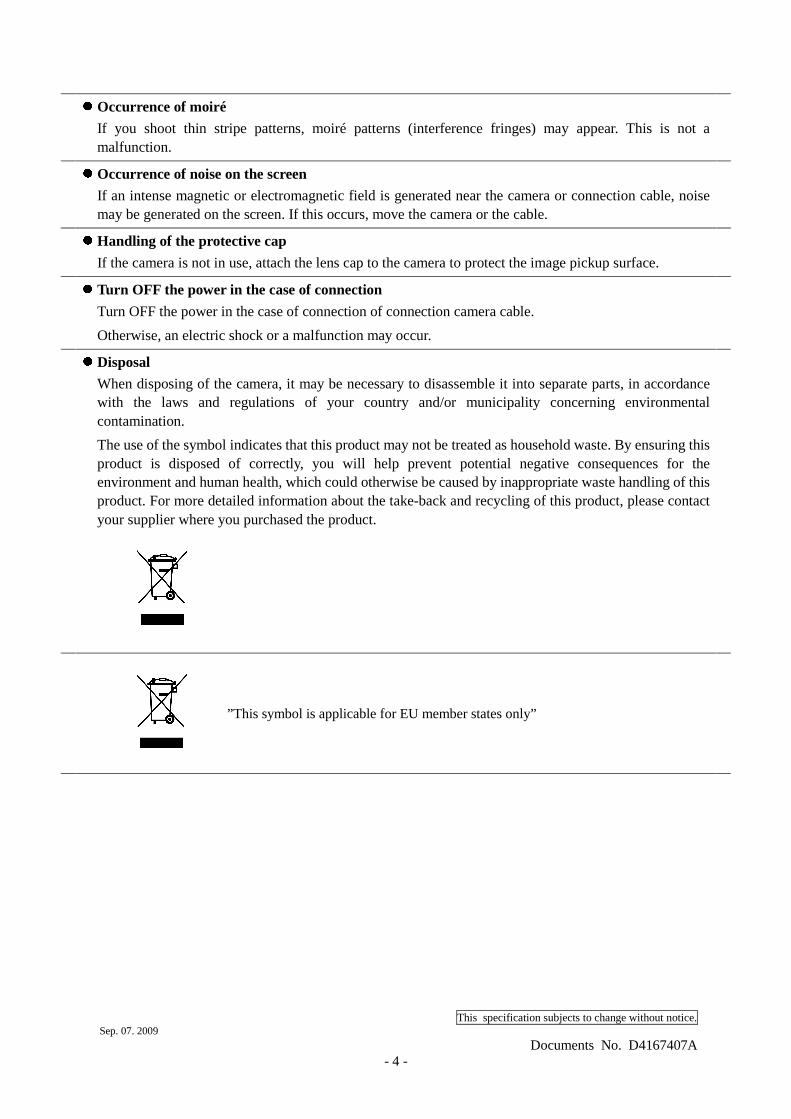
� Disposal
When disposing of the camera, it may be necessary to disassemble it into separate parts, in accordance with the laws and regulations of your country and/or municipality concerning environmental contamination.
The use of the symbol indicates that this product may not be treated as household waste. By ensuring this product is disposed of correctly, you will help prevent potential negative consequences for the environment and human health, which could otherwise be caused by inappropriate waste handling of this product. For more detailed information about the take-back and recycling of this product, please contact your supplier where you purchased the product.
”This symbol is applicable for EU member states only”
This specification subjects to change without notice. Sep. 07. 2009
Documents No. D4167407A - 5 -
1. Overview
This CCD camera is a high-resolution camera that features all pixel readout mode 1/1.8 CCD.
Model Power supply InterfaceCSCU30BC18 Camera Link connector Power over Camera Link
CSCU30BC18-01 I/O Connector Camera Link
2. Features
(1) High resolution
High pixel density CCD (number of effective pixels 2.01M, number of total pixels 2.11M) is used.
(2) Square grids
The CCD pixels arrayed in square grids facilitates computation processing.
(3) Full-frame shutter
Since all pixels are output even by shutter operation, high resolution can be achieved,
without deteriorating the vertical resolution.
(4) Camera link interface (Power supply type) PoCL
The interface of image output and the camera control complies with the Camera Link standard.
By using a camera link frame grabber board for camera link of possible power supplies, the shot
image can be transferred to PC at high speed, various camera controls can be performed from PC, and
the power supply of the camera can be supplied with one cable. The camera link model that is not the
power supply type is CSCU30BC18-01
(5) All-pixel readout mode (normal mode)
All pixel signals (in the effective area) are output in approximately 1/30 second.
(6) Programming partial scan mode
Partial scan within the range arbitrary from 50 lines to 1236 lines is possible.
(7) High-speed draft readout mode
By reading 2 lines from every 8 lines, all signals in the effective area are output in approximately in
1/89 second.
(8) Random trigger shutter
By external trigger signal input, the shot image can be grabbed at an arbitrary timing.
(9) Multiple-shutter
By external trigger signal input, the shot image can be grabbed at an arbitrary timing and the
accumulated shot images can be output at an arbitrary timing.

This specification subjects to change without notice. Sep. 07. 2009
Documents No. D4167407A - 6 -
3. Configuration
(1) Camera body ·········································································· 1
(2) Accessories
Instruction Manual (Japanese) ·················································· 1
Instruction Manual (English) ···················································· 1
4. Optional parts
(1) I/O cable Model name: CPRC3700-**
(2) Camera Link cable Model name: 14B26-SZLB-**-0LC
(3) Camera adapter Model name: CA170
(4) Camera mounting kit Model name: CPT4000CL
*NOTE: Application software is not supplied as a standard item.
*NOTE: If you need PoCL cable, contact your dealer / distributor.
Notes on optional parts and compliance with safety standard conditions:
We assure the compliance of this camera with the safety standard when it is used in combination with
the optional parts listed above.
If you use the camera in combination with parts other than specified by our company, you are responsible
for finally confirming the compliance with the safety standard by using the entire machine/equipment.
This specification subjects to change without notice. Sep. 07. 2009
Documents No. D4167407A - 7 -
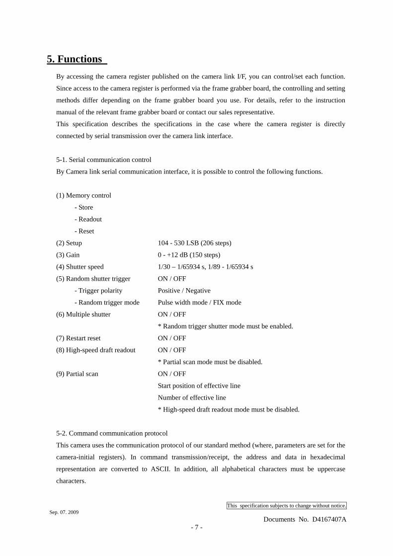
5. Functions
By accessing the camera register published on the camera link I/F, you can control/set each function.
Since access to the camera register is performed via the frame grabber board, the controlling and setting
methods differ depending on the frame grabber board you use. For details, refer to the instruction
manual of the relevant frame grabber board or contact our sales representative.
This specification describes the specifications in the case where the camera register is directly
connected by serial transmission over the camera link interface.
5-1. Serial communication control
By Camera link serial communication interface, it is possible to control the following functions.
(1) Memory control
- Store
- Readout
- Reset
(2) Setup 104 - 530 LSB (206 steps)
(3) Gain 0 - +12 dB (150 steps)
(4) Shutter speed 1/30 – 1/65934 s, 1/89 - 1/65934 s
(5) Random shutter trigger ON / OFF
- Trigger polarity Positive / Negative
- Random trigger mode Pulse width mode / FIX mode
(6) Multiple shutter ON / OFF
* Random trigger shutter mode must be enabled.
(7) Restart reset ON / OFF
(8) High-speed draft readout ON / OFF
* Partial scan mode must be disabled.
(9) Partial scan ON / OFF
Start position of effective line
Number of effective line
* High-speed draft readout mode must be disabled.
5-2. Command communication protocol
This camera uses the communication protocol of our standard method (where, parameters are set for the
camera-initial registers). In command transmission/receipt, the address and data in hexadecimal
representation are converted to ASCII. In addition, all alphabetical characters must be uppercase
characters.
This specification subjects to change without notice. Sep. 07. 2009
Documents No. D4167407A - 8 -
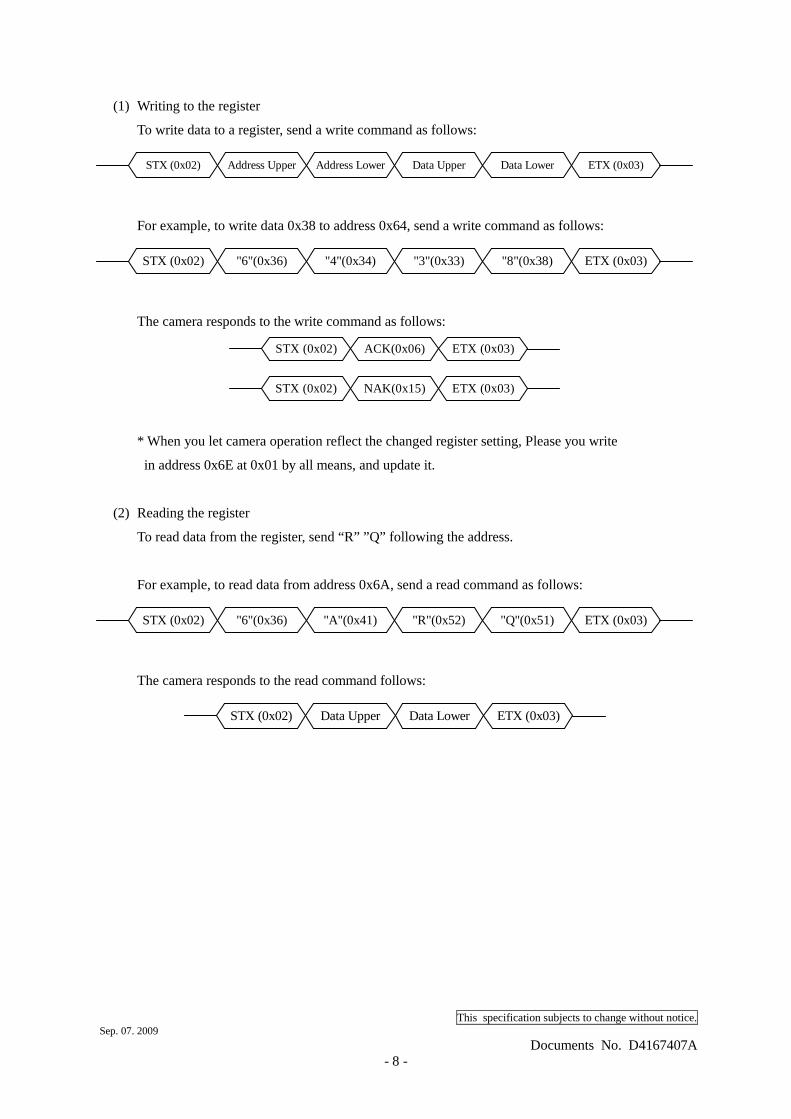
(1) Writing to the register
To write data to a register, send a write command as follows:
STX (0x02) Data UpperAddress LowerAddress Upper Data Lower ETX (0x03)
For example, to write data 0x38 to address 0x64, send a write command as follows:
STX (0x02) "3"(0x33)"4"(0x34)"6"(0x36) "8"(0x38) ETX (0x03)
The camera responds to the write command as follows:
STX (0x02) ACK(0x06) ETX (0x03)
STX (0x02) NAK(0x15) ETX (0x03)
* When you let camera operation reflect the changed register setting, Please you write
in address 0x6E at 0x01 by all means, and update it.
(2) Reading the register
To read data from the register, send “R” ”Q” following the address.
For example, to read data from address 0x6A, send a read command as follows:
STX (0x02) "R"(0x52)"A"(0x41)"6"(0x36) "Q"(0x51) ETX (0x03)
The camera responds to the read command follows:
STX (0x02) Data Upper Data Lower ETX (0x03)
This specification subjects to change without notice. Sep. 07. 2009
Documents No. D4167407A - 9 -
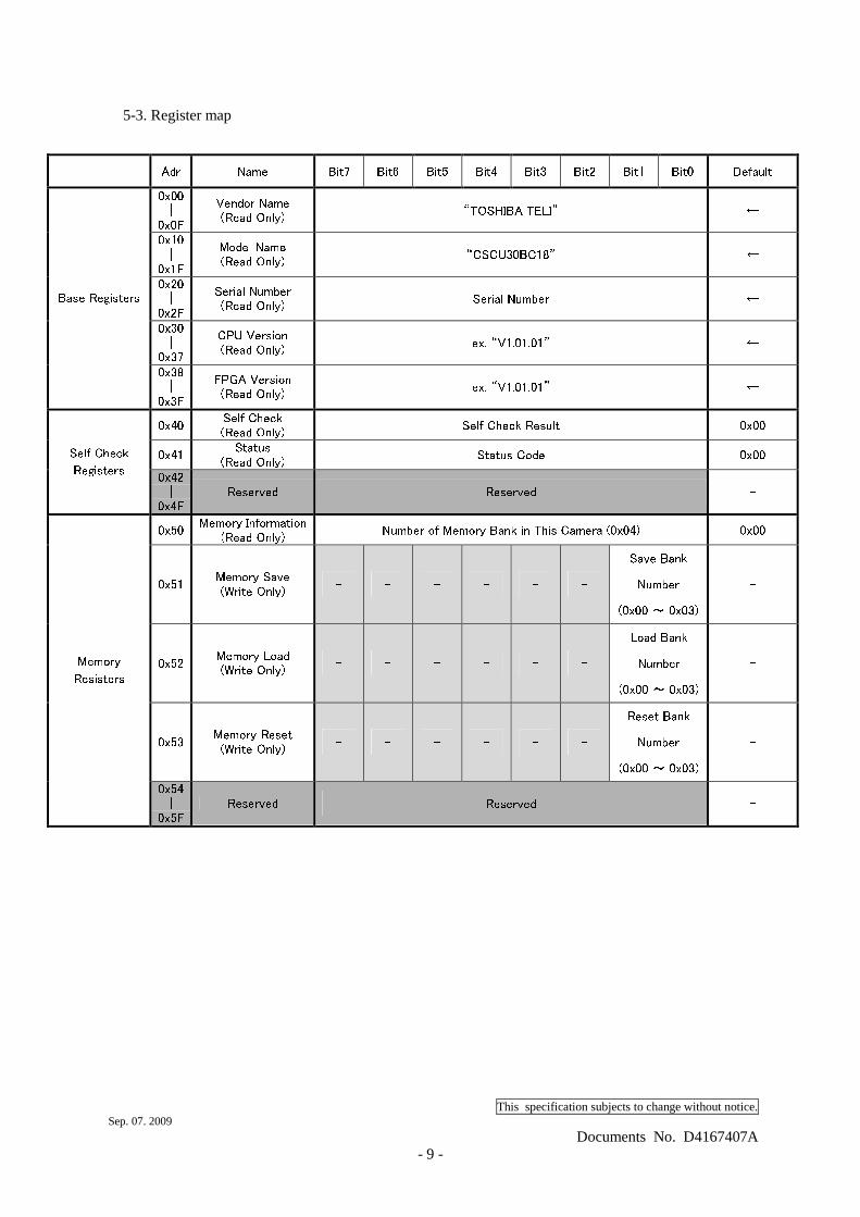
5-3. Register map
Adr Name Bit7 Bit6 Bit5 Bit4 Bit3 Bit2 Bit1 Bit0 Default 0x00 | 0x0F Vendor Name (Read Only) “TOSHIBA TELI” ← 0x10 | 0x1F Model Name (Read Only) “CSCU30BC18” ← 0x20 | 0x2F Serial Number (Read Only) Serial Number ← 0x30 | 0x37 CPU Version (Read Only) ex. “V1.01.01” ← Base Registers 0x38 | 0x3F FPGA Version (Read Only) ex. “V1.01.01” ← 0x40 Self Check (Read Only) Self Check Result 0x00 0x41 Status (Read Only) Status Code 0x00 Self Check Registers 0x42 | 0x4F Reserved Reserved - 0x50 Memory Information (Read Only) Number of Memory Bank in This Camera (0x04) 0x00 0x51 Memory Save (Write Only) - - - - - - Save Bank Number (0x00 ~ 0x03) - 0x52 Memory Load (Write Only) - - - - - - Load Bank Number (0x00 ~ 0x03) - 0x53 Memory Reset (Write Only) - - - - - - Reset Bank Number (0x00 ~ 0x03) - Memory Resisters 0x54 | 0x5F Reserved Reserved -
This specification subjects to change without notice. Sep. 07. 2009
Documents No. D4167407A - 10 -
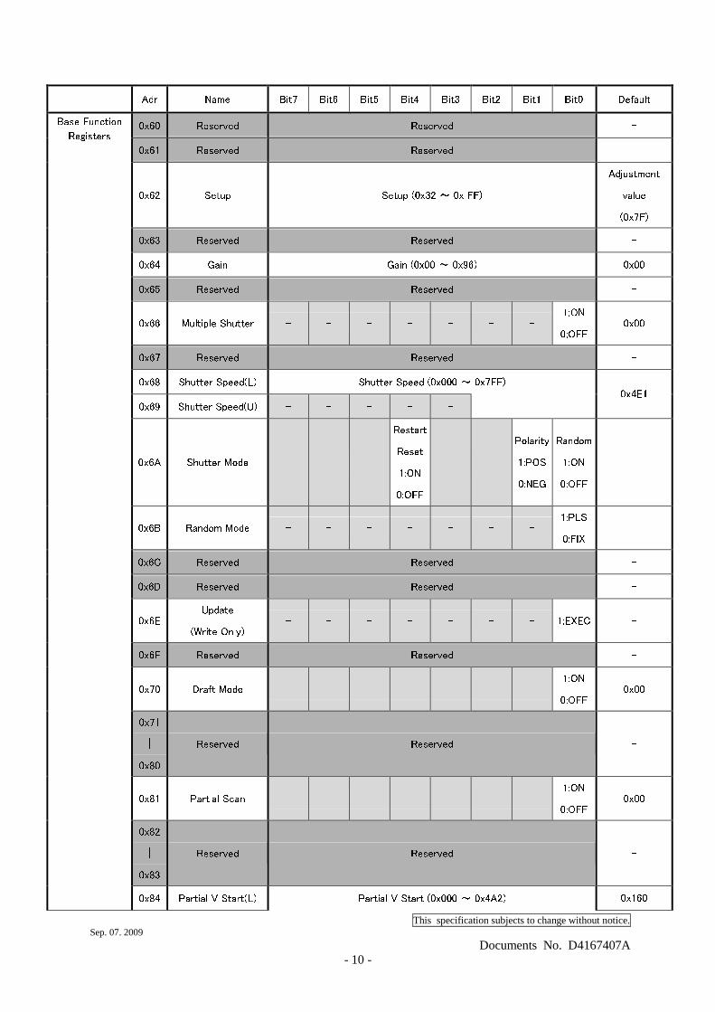
Adr Name Bit7 Bit6 Bit5 Bit4 Bit3 Bit2 Bit1 Bit0 Default 0x60 Reserved Reserved - 0x61 Reserved Reserved - 0x62 Setup Setup (0x32 ~ 0x FF) Adjustment value (0x7F) 0x63 Reserved Reserved - 0x64 Gain Gain (0x00 ~ 0x96) 0x00 0x65 Reserved Reserved - 0x66 Multiple Shutter - - - - - - - 1:ON 0:OFF 0x00 0x67 Reserved Reserved - 0x68 Shutter Speed(L) Shutter Speed (0x000 ~ 0x7FF) 0x69 Shutter Speed(U) - - - - - 0x4E1 0x6A Shutter Mode - - - Restart Reset 1:ON 0:OFF - - Polarity 1:POS 0:NEG Random 1:ON 0:OFF 0x6B Random Mode - - - - - - - 1:PLS 0:FIX 0x6C Reserved Reserved - 0x6D Reserved Reserved - 0x6E Update (Write Only) - - - - - - - 1:EXEC - 0x6F Reserved Reserved - 0x70 Draft Mode - - - - - - - 1:ON 0:OFF 0x00 0x71 | 0x80 Reserved Reserved - 0x81 Partial Scan - - - - - - - 1:ON 0:OFF 0x00 0x82 | 0x83 Reserved Reserved -
Base Function Registers
0x84 Partial V Start(L) Partial V Start (0x000 ~ 0x4A2) 0x160
This specification subjects to change without notice. Sep. 07. 2009
Documents No. D4167407A - 11 -
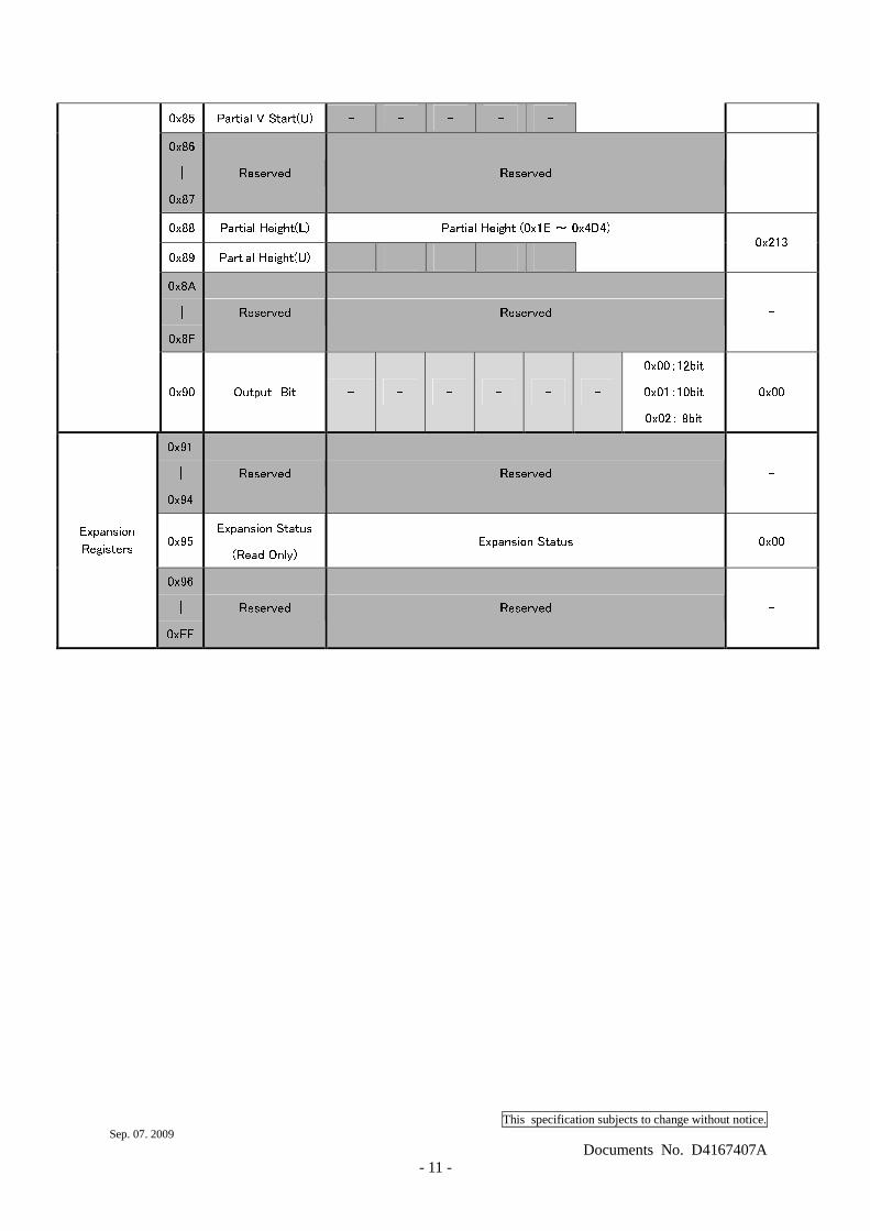
0x85 Partial V Start(U) - - - - - 0x86 | 0x87 Reserved Reserved - 0x88 Partial Height(L) Partial Height (0x1E ~ 0x4D4) 0x89 Partial Height(U) - - - - - 0x213 0x8A | 0x8F Reserved Reserved - 0x90 Output Bit - - - - - - 0x00:12bit 0x01:10bit 0x02: 8bit 0x00 0x91 | 0x94 Reserved Reserved - 0x95 Expansion Status (Read Only) Expansion Status 0x00 Expansion Registers 0x96 | 0xFF Reserved Reserved -
This specification subjects to change without notice. Sep. 07. 2009
Documents No. D4167407A - 12 -
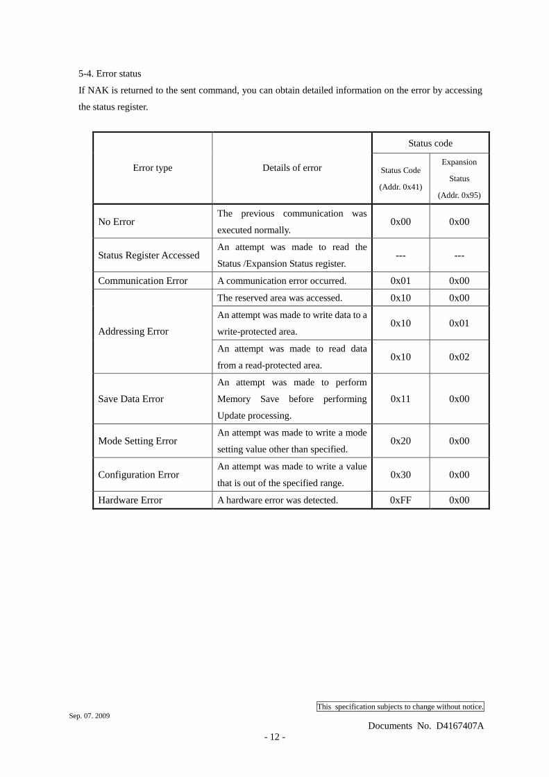
5-4. Error status
If NAK is returned to the sent command, you can obtain detailed information on the error by accessing
the status register.
Status code
Error type Details of error Status Code
(Addr. 0x41)
Expansion
Status
(Addr. 0x95)
No Error The previous communication was
executed normally. 0x00 0x00
Status Register Accessed An attempt was made to read the
Status /Expansion Status register. --- ---
Communication Error A communication error occurred. 0x01 0x00
The reserved area was accessed. 0x10 0x00
An attempt was made to write data to a
write-protected area. 0x10 0x01
Addressing Error
An attempt was made to read data
from a read-protected area. 0x10 0x02
Save Data Error
An attempt was made to perform
Memory Save before performing
Update processing.
0x11 0x00
Mode Setting Error An attempt was made to write a mode
setting value other than specified. 0x20 0x00
Configuration Error An attempt was made to write a value
that is out of the specified range. 0x30 0x00
Hardware Error A hardware error was detected. 0xFF 0x00
This specification subjects to change without notice. Sep. 07. 2009
Documents No. D4167407A - 13 -
5-5. Register setting value updating Address: 0x6E, Bit: 0, Value: 1
The changed register setting value is reflected on the camera operation. Only writing a value in each
register does not cause the value to be reflected on the camera operation. Register value updating
must be executed before the changed setting value can be reflected on the camera action. To save
the setting value in memory, the register setting value must be updated beforehand. Otherwise, an
execution error occurs and the setting value is unable to be saved in memory.
5-6. Readout mode
Video is output from the camera link connector. The output video can be grabbed by the frame
grabber board. The frame rate and resolution of output images that this model supports are as
furrows:
- All pixel readout Approximately 30 fps, 1628 (H) x 1236 (V)
- Partial scan Approximately 30 fps to 183 fps, 1628 (H) x 552 to 1236 (V)
- High-speed draft readout Approximately 89 fps, 1628 (H) x 309 (V)
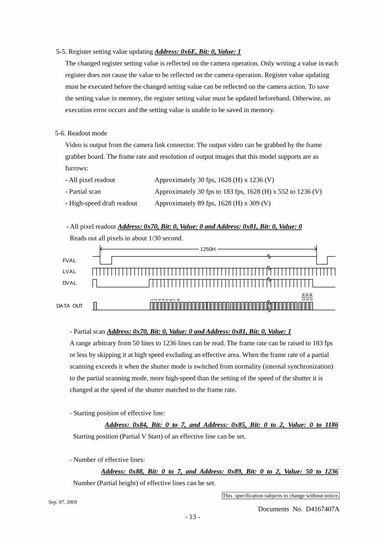
- All pixel readout Address: 0x70, Bit: 0, Value: 0 and Address: 0x81, Bit: 0, Value: 0
Reads out all pixels in about 1/30 second.
FVAL
DATA OUT
LVAL
DVAL
1 2 3 4 5 6 7 8 1236
1235
1234
1250H
- Partial scan Address: 0x70, Bit: 0, Value: 0 and Address: 0x81, Bit: 0, Value: 1
A range arbitrary from 50 lines to 1236 lines can be read. The frame rate can be raised to 183 fps
or less by skipping it at high speed excluding an effective area. When the frame rate of a partial
scanning exceeds it when the shutter mode is switched from normality (internal synchronization)
to the partial scanning mode, more high-speed than the setting of the speed of the shutter it is
changed at the speed of the shutter matched to the frame rate.
- Starting position of effective line:
Address: 0x84, Bit: 0 to 7, and Address: 0x85, Bit: 0 to 2, Value: 0 to 1186
Starting position (Partial V Start) of an effective line can be set.
- Number of effective lines:
Address: 0x88, Bit: 0 to 7, and Address: 0x89, Bit: 0 to 2, Value: 50 to 1236
Number (Partial height) of effective lines can be set.
This specification subjects to change without notice. Sep. 07. 2009
Documents No. D4167407A - 14 -
The frame rate is obtained in the following calculations.
( )1920
1072
8
13___1236
_18
15__3
61×× ++−+
+ + ++=
−HeightPartialStartVPartial
HeightPartialStartVPartial
FrameLate
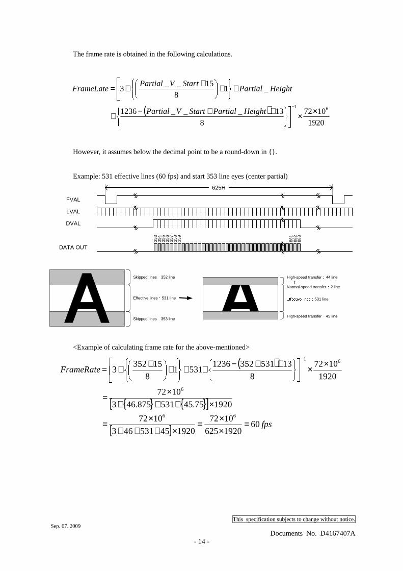
However, it assumes below the decimal point to be a round-down in {}.
Example: 531 effective lines (60 fps) and start 353 line eyes (center partial)
FVAL
DATA OUT
LVAL
DVAL
353
355
356
357
358
359
883
882
881
625H
354
Effective lines : 531 line
High-speed transfer : 45 line
High-speed transfer : 44 line +Normal-speed transfer : 2 line
Effective lines : 531 line
Skipped lines : 353 line
Skipped lines : 352 line
<Example of calculating frame rate for the above-mentioned>
( )
{ } { }[ ]
[ ] fps
FrameRate
601920625
1072
192045531463
1072
192075.45531875.463
1072
1920
1072
8
1353135212365311
8
153523
66
6
61
=××=
×+++×=
×+++×=
×× ++−+ + + ++=−
This specification subjects to change without notice. Sep. 07. 2009
Documents No. D4167407A - 15 -
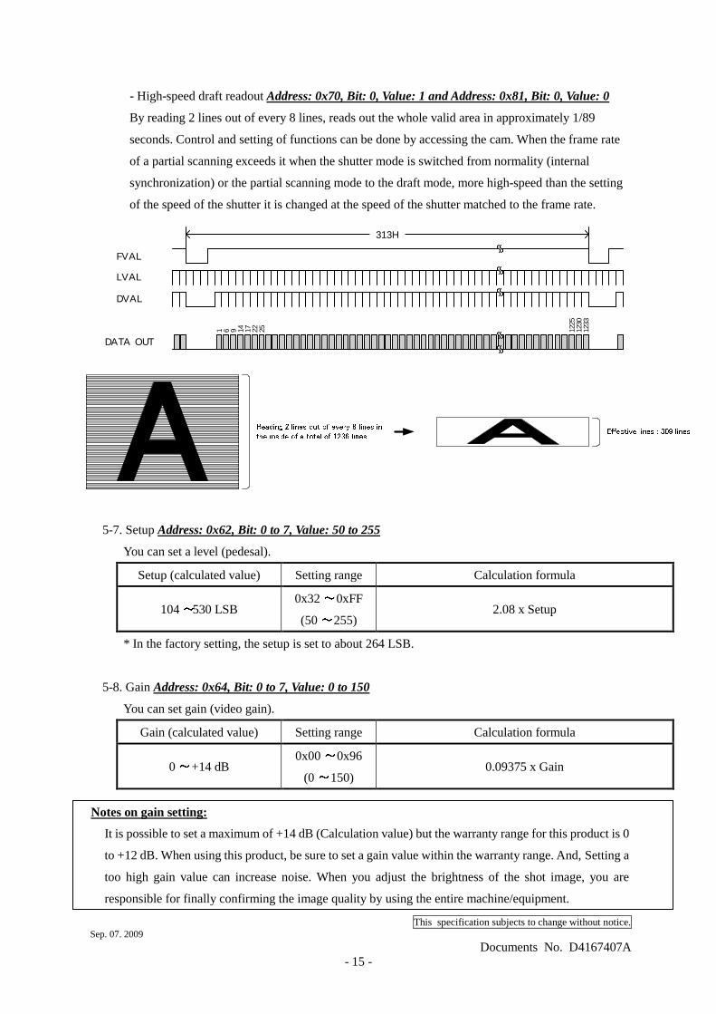
- High-speed draft readout Address: 0x70, Bit: 0, Value: 1 and Address: 0x81, Bit: 0, Value: 0
By reading 2 lines out of every 8 lines, reads out the whole valid area in approximately 1/89
seconds. Control and setting of functions can be done by accessing the cam. When the frame rate
of a partial scanning exceeds it when the shutter mode is switched from normality (internal
synchronization) or the partial scanning mode to the draft mode, more high-speed than the setting
of the speed of the shutter it is changed at the speed of the shutter matched to the frame rate.
FVAL
DATA OUT
LVAL
DVAL
1 6 9 14 17 22 25 1233
1230
1225
313H
Effective lines : 309 linesReading 2 lines out of every 8 lines inthe inside of a total of 1236 lines
5-7. Setup Address: 0x62, Bit: 0 to 7, Value: 50 to 255
You can set a level (pedesal).
Setup (calculated value) Setting range Calculation formula ~104 530 LSB ~0x32 0xFF ~(50 255)
2.08 x Setup
* In the factory setting, the setup is set to about 264 LSB.
5-8. Gain Address: 0x64, Bit: 0 to 7, Value: 0 to 150
You can set gain (video gain).
Gain (calculated value) Setting range Calculation formula ~0 +14 dB ~0x00 0x96 ~(0 150)
0.09375 x Gain
Notes on gain setting:
It is possible to set a maximum of +14 dB (Calculation value) but the warranty range for this product is 0
to +12 dB. When using this product, be sure to set a gain value within the warranty range. And, Setting a
too high gain value can increase noise. When you adjust the brightness of the shot image, you are
responsible for finally confirming the image quality by using the entire machine/equipment.
This specification subjects to change without notice. Sep. 07. 2009
Documents No. D4167407A - 16 -
5-9. Electronic shutter Address: 0x68, Bit: 0 to 7, and Address: 0x69, Bit:0 to 2, Value: 0 to 2047
You can set the shutter speed. The setting range differs depending on the output mode.
Readout mode Shutter speed
(calculated value) Setting range Calculation formula
All pixel readout ~1/30 1/65,934 s ~0x4E1 0x000 ~(1249 0)
Partial scan ~1/30 1/65,934 s ~0x4E1 0x000 ( ~ )1249 0
(1092 CLK + 1920 CLK x Shutter Speed) / 72 MHz
High-speed draft readout ~1/89 1/65,934 s ~0x138 0x000 ~(312 0)
(1092 CLK + 2568 CLK x Shutter Speed) / 72 MHz
<For example, when you set shutter speed in 1/200 s (at All pixel readout, Partial scan)>
(1092 CLK + 1920 CLK x Shutter Speed) / 72 MHz = 1/200 s
1092+1920 x Shutter speed = 36x106 / 200
1920 x Shutter speed = 72x106 / 200 - 1092 ∴∴∴∴Shutter speed = (72x106 / 200 – 1092) / 1920 = 186.931... ≑≑≑≑ 187 = 0x0BB
when you set shutter speed in 1/200 s, Please send a write command as follows.
(1) to write data 0xBB to address 0x68, to write data 0x00 to address 0x69.
(2) to write data 0x01 to address 0x6E
5-10. Random trigger shutter Address: 0x6A, Bit: 0, Value: 1
In the random trigger shutter mode, you can shoot and grab an image at an arbitrary timing by
trigger signal input from the external.
- External trigger signals can be input either from the camera link I/F CC1 or I/O connector.
- If polarity is set to negative polarity, exposure starts at the falling edge of the trigger.
- The random trigger shutter of this camera can be operated in two types of mode: fixed mode and
pulse width mode. How to determine the exposure time differs depending on the mode.
This specification subjects to change without notice. Sep. 07. 2009
Documents No. D4167407A - 17 -
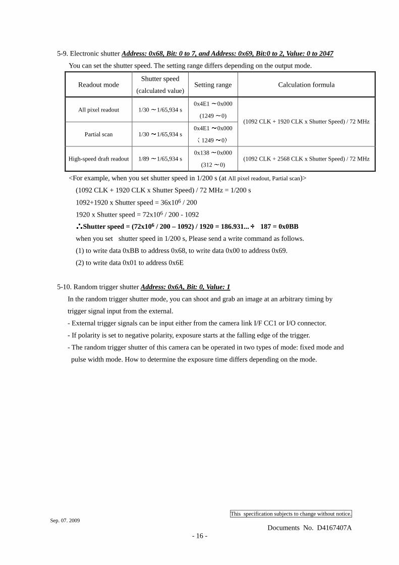
1) Fixed mode Address: 0x6B, Bit: 0, Value: 0
- The exposure time is determined by the setting value for the shutter speed.
- FVAL is output in sync with the first LVAL after the end of exposure time.
FVAL
DATA OUT
LVAL
DVAL
exposure time
TRIG
CCD
approx. 2.0μs
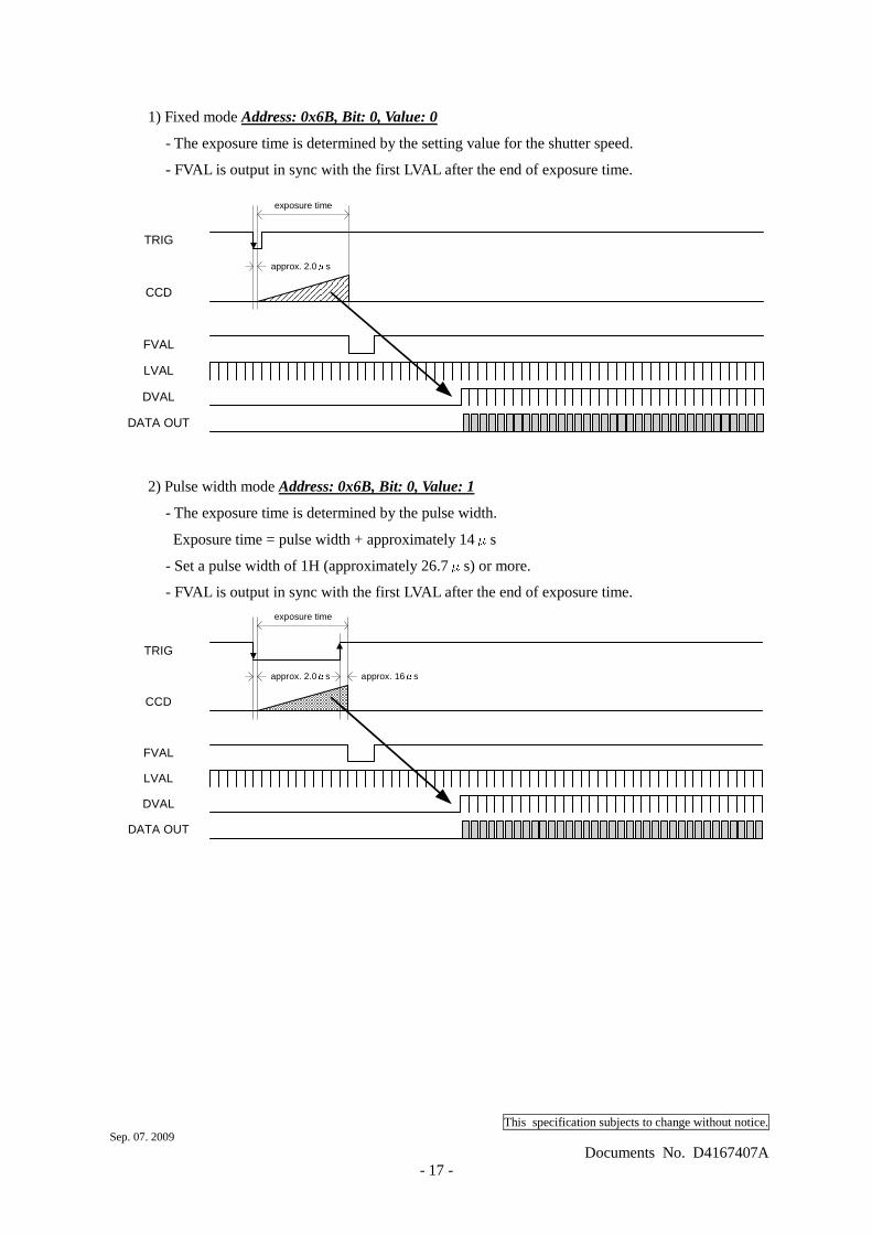
2) Pulse width mode Address: 0x6B, Bit: 0, Value: 1
- The exposure time is determined by the pulse width.
Exposure time = pulse width + approximately 14μs
- Set a pulse width of 1H (approximately 26.7μs) or more.
- FVAL is output in sync with the first LVAL after the end of exposure time.
FVAL
DATA OUT
LVAL
DVAL
exposure time
TRIG
CCD
approx. 2.0μs approx. 16μs
This specification subjects to change without notice. Sep. 07. 2009
Documents No. D4167407A - 18 -
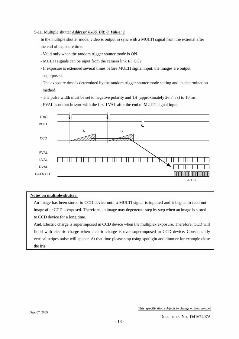
5-11. Multiple shutter Address: 0x66, Bit: 0, Value: 1
In the multiple shutter mode, video is output in sync with a MULTI signal from the external after
the end of exposure time.
- Valid only when the random trigger shutter mode is ON.
- MULTI signals can be input from the camera link I/F CC2.
- If exposure is extended several times before MULTI signal input, the images are output
superposed.
- The exposure time is determined by the random trigger shutter mode setting and its determination
method.
- The pulse width must be set to negative polarity and 1H (approximately 26.7μs) to 10 ms.
- FVAL is output in sync with the first LVAL after the end of MULTI signal input.
FVAL
DATA OUT
LVAL
DVAL
MULTI
CCD
TRIG
A B
A + B
Notes on multiple-shutter:
An image has been stored to CCD device until a MULTI signal is inputted and it begins to read out
image after CCD is exposed. Therefore, an image may degenerate step by step when an image is stored
to CCD device for a long time.
And, Electric charge is superimposed in CCD device when the multiplex exposure. Therefore, CCD will
flood with electric charge when electric charge is over superimposed in CCD device. Consequently
vertical stripes noise will appear. At that time please stop using spotlight and dimmer for example close
the iris.
This specification subjects to change without notice. Sep. 07. 2009
Documents No. D4167407A - 19 -
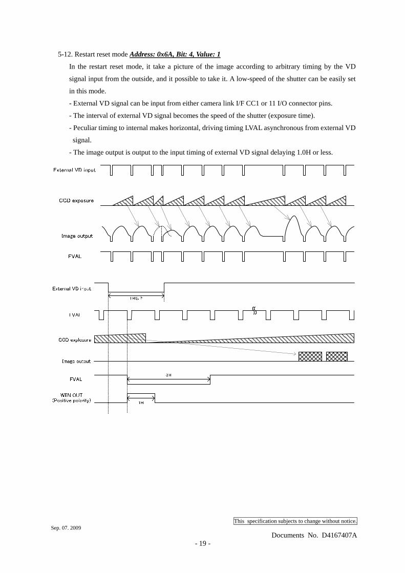
5-12. Restart reset mode Address: 0x6A, Bit: 4, Value: 1
In the restart reset mode, it take a picture of the image according to arbitrary timing by the VD
signal input from the outside, and it possible to take it. A low-speed of the shutter can be easily set
in this mode.
- External VD signal can be input from either camera link I/F CC1 or 11 I/O connector pins.
- The interval of external VD signal becomes the speed of the shutter (exposure time).
- Peculiar timing to internal makes horizontal, driving timing LVAL asynchronous from external VD
signal.
- The image output is output to the input timing of external VD signal delaying 1.0H or less.
This specification subjects to change without notice. Sep. 07. 2009
Documents No. D4167407A - 20 -
5-13. Saving value memory
Each setting value can be saved in the memory inside the camera.
- The contents of the memory is held even after the power supply is turned off.
- The memory consists of 4 banks. For each table, you can save/readout the setting value
independently, as well as reset the setting value to the initial factory setting.
- You can set the number of the memory bank to be read out when the power supply is turned on, by
using the relevant dip switch on the back surface of the main body.
(1) Memory save Address: 0x51, Bit: 0 to 1, Value: 0 to 3
- When you write to the register the number of the memory bank to which the setting value is to be
saved, the setting value of each register is saved in the internal memory.
- If you have not executed "Update" after changing the setting value (reset address 0x6E to 0x01), an
execution error occurs and the setting value is not saved in the memory. Be sure to execute
"Update" before saving the setting value.
(2) Memory readout Address: 0x52, Bit: 0 to 1, Value: 0 to 3
- When you write to the register the number of the memory bank from which the setting value is to
be read out, the setting value is read out from the internal memory and set.
(3) Memory reset Address: 0x53, Bit: 0 to 1, Value: 0 to 3
- When you write to the register the number of the memory bank to be reset, the initial factory setting
value is read out from the internal memory and set.
5-14. Output bit Address: 0x90, Bit: 0 to 1, Value: 0 to 2
You can set gray scale per pixel. The initial factory setting is 12 bits.
This specification subjects to change without notice. Sep. 07. 2009
Documents No. D4167407A - 21 -
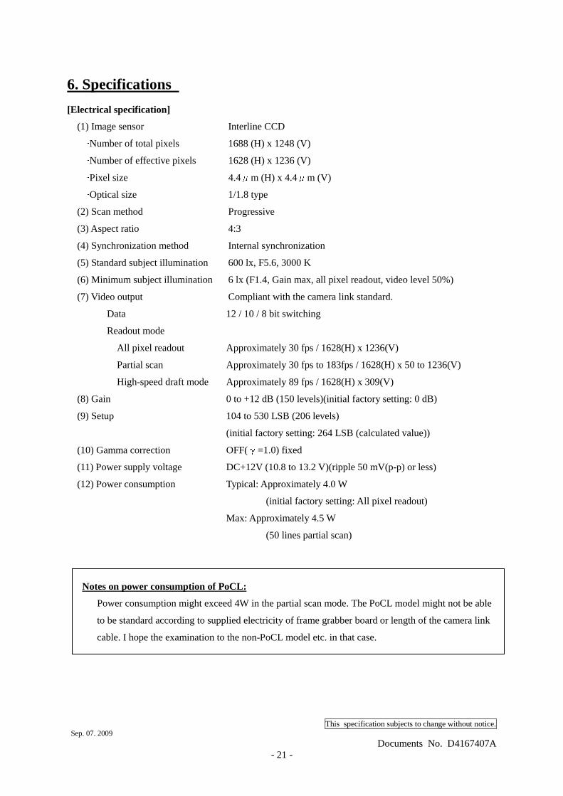
6. Specifications
[Electrical specification]
(1) Image sensor Interline CCD ·Number of total pixels 1688 (H) x 1248 (V) ·Number of effective pixels 1628 (H) x 1236 (V) ·Pixel size 4.4μm (H) x 4.4μm (V) ·Optical size 1/1.8 type
(2) Scan method Progressive
(3) Aspect ratio 4:3
(4) Synchronization method Internal synchronization
(5) Standard subject illumination 600 lx, F5.6, 3000 K
(6) Minimum subject illumination 6 lx (F1.4, Gain max, all pixel readout, video level 50%)
(7) Video output Compliant with the camera link standard.
Data 12 / 10 / 8 bit switching
Readout mode
All pixel readout Approximately 30 fps / 1628(H) x 1236(V)
Partial scan Approximately 30 fps to 183fps / 1628(H) x 50 to 1236(V)
High-speed draft mode Approximately 89 fps / 1628(H) x 309(V)
(8) Gain 0 to +12 dB (150 levels)(initial factory setting: 0 dB)
(9) Setup 104 to 530 LSB (206 levels)
(initial factory setting: 264 LSB (calculated value))
(10) Gamma correction OFF(γ=1.0) fixed
(11) Power supply voltage DC+12V (10.8 to 13.2 V)(ripple 50 mV(p-p) or less)
(12) Power consumption Typical: Approximately 4.0 W
(initial factory setting: All pixel readout)
Max: Approximately 4.5 W
(50 lines partial scan)
Notes on power consumption of PoCL:
Power consumption might exceed 4W in the partial scan mode. The PoCL model might not be able
to be standard according to supplied electricity of frame grabber board or length of the camera link
cable. I hope the examination to the non-PoCL model etc. in that case.
This specification subjects to change without notice. Sep. 07. 2009
Documents No. D4167407A - 22 -
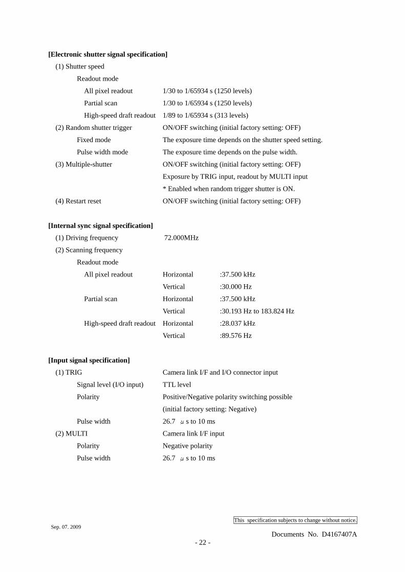
[Electronic shutter signal specification]
(1) Shutter speed
Readout mode
All pixel readout 1/30 to 1/65934 s (1250 levels)
Partial scan 1/30 to 1/65934 s (1250 levels)
High-speed draft readout 1/89 to 1/65934 s (313 levels)
(2) Random shutter trigger ON/OFF switching (initial factory setting: OFF)
Fixed mode The exposure time depends on the shutter speed setting.
Pulse width mode The exposure time depends on the pulse width.
(3) Multiple-shutter ON/OFF switching (initial factory setting: OFF)
Exposure by TRIG input, readout by MULTI input
* Enabled when random trigger shutter is ON.
(4) Restart reset ON/OFF switching (initial factory setting: OFF)
[Internal sync signal specification]
(1) Driving frequency 72.000MHz
(2) Scanning frequency
Readout mode
All pixel readout Horizontal :37.500 kHz
Vertical :30.000 Hz
Partial scan Horizontal :37.500 kHz
Vertical :30.193 Hz to 183.824 Hz
High-speed draft readout Horizontal :28.037 kHz
Vertical :89.576 Hz
[Input signal specification]
(1) TRIG Camera link I/F and I/O connector input
Signal level (I/O input) TTL level
Polarity Positive/Negative polarity switching possible
(initial factory setting: Negative)
Pulse width 26.7 μs to 10 ms
(2) MULTI Camera link I/F input
Polarity Negative polarity
Pulse width 26.7 μs to 10 ms
This specification subjects to change without notice. Sep. 07. 2009
Documents No. D4167407A - 23 -
[Output signal specification]
(1) WEN I/O connector output
Signal level 4 V (p-p)
Polarity Positive polarity
Pulse width Approximately 26.7 μs
(2) VD I/O Connector output
Signal level 4 V (p-p)
Polarity Negative polarity
Pulse width Approximately 80 μs
This specification subjects to change without notice. Sep. 07. 2009
Documents No. D4167407A - 24 -
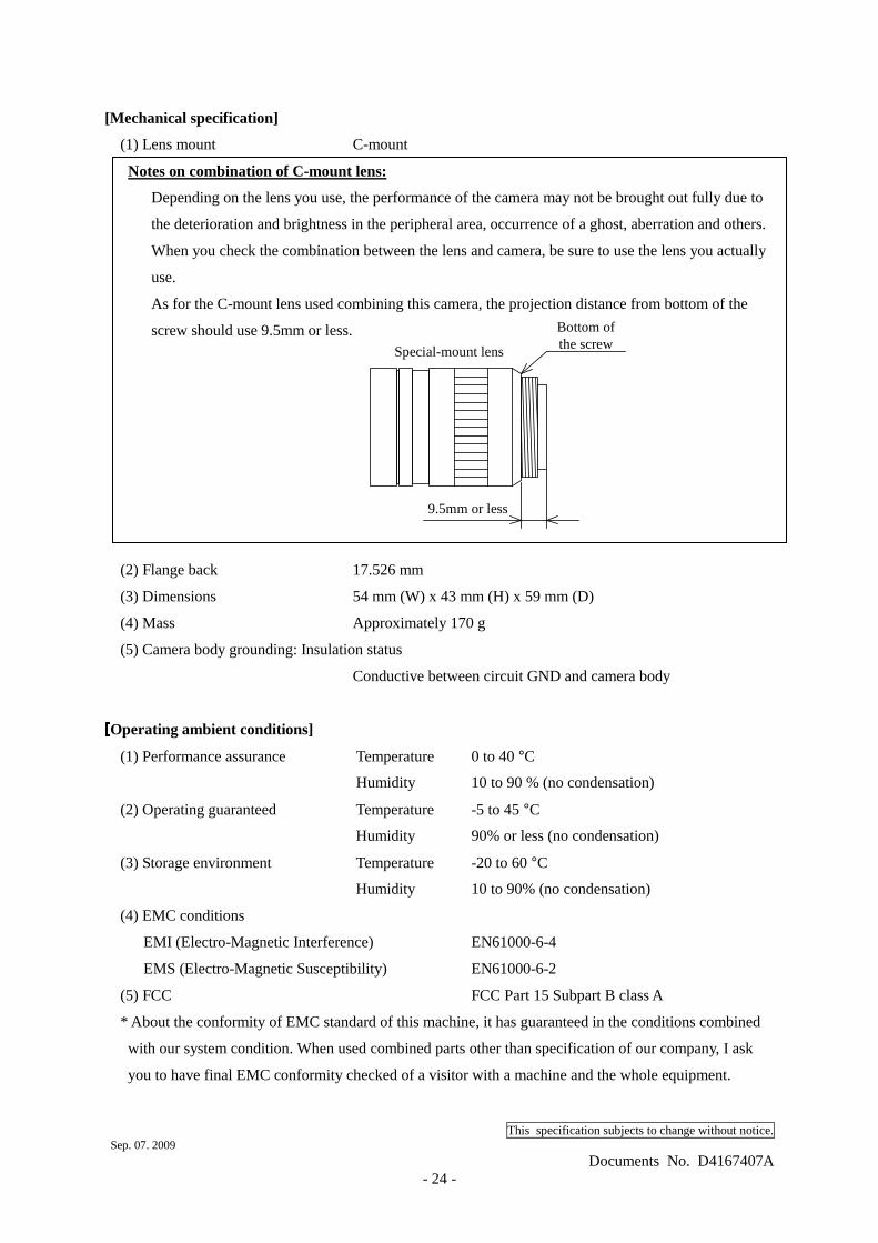
[Mechanical specification]
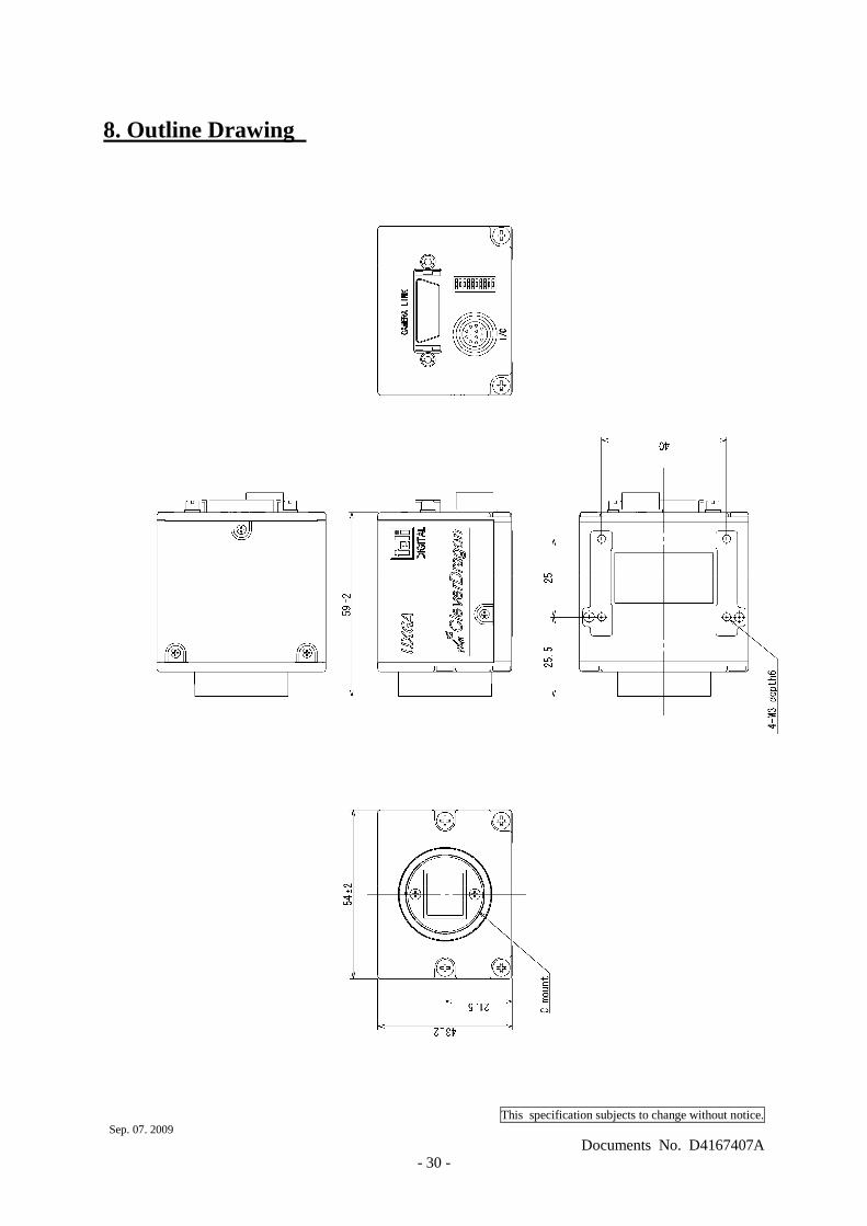
(1) Lens mount C-mount
Notes on combination of C-mount lens:
Depending on the lens you use, the performance of the camera may not be brought out fully due to
the deterioration and brightness in the peripheral area, occurrence of a ghost, aberration and others.
When you check the combination between the lens and camera, be sure to use the lens you actually
use.
As for the C-mount lens used combining this camera, the projection distance from bottom of the
screw should use 9.5mm or less.
(2) Flange back 17.526 mm
(3) Dimensions 54 mm (W) x 43 mm (H) x 59 mm (D)
(4) Mass Approximately 170 g
(5) Camera body grounding: Insulation status
Conductive between circuit GND and camera body [[[[Operating ambient conditions]
(1) Performance assurance Temperature 0 to 40 °C
Humidity 10 to 90 % (no condensation)
(2) Operating guaranteed Temperature -5 to 45 °C
Humidity 90% or less (no condensation)
(3) Storage environment Temperature -20 to 60 °C
Humidity 10 to 90% (no condensation)
(4) EMC conditions
EMI (Electro-Magnetic Interference) EN61000-6-4
EMS (Electro-Magnetic Susceptibility) EN61000-6-2
(5) FCC FCC Part 15 Subpart B class A
* About the conformity of EMC standard of this machine, it has guaranteed in the conditions combined
with our system condition. When used combined parts other than specification of our company, I ask
you to have final EMC conformity checked of a visitor with a machine and the whole equipment.
9.5mm or less
Special-mount lens
Bottom ofthe screw
This specification subjects to change without notice. Sep. 07. 2009
Documents No. D4167407A - 25 -
[Communication specification]
(1) Communication speed 9600/19200/38400 bps
(2) Data bit 8
(3) Parity None
(4) Stop bit 1
(5) Handshake None [Connector pin assignment]
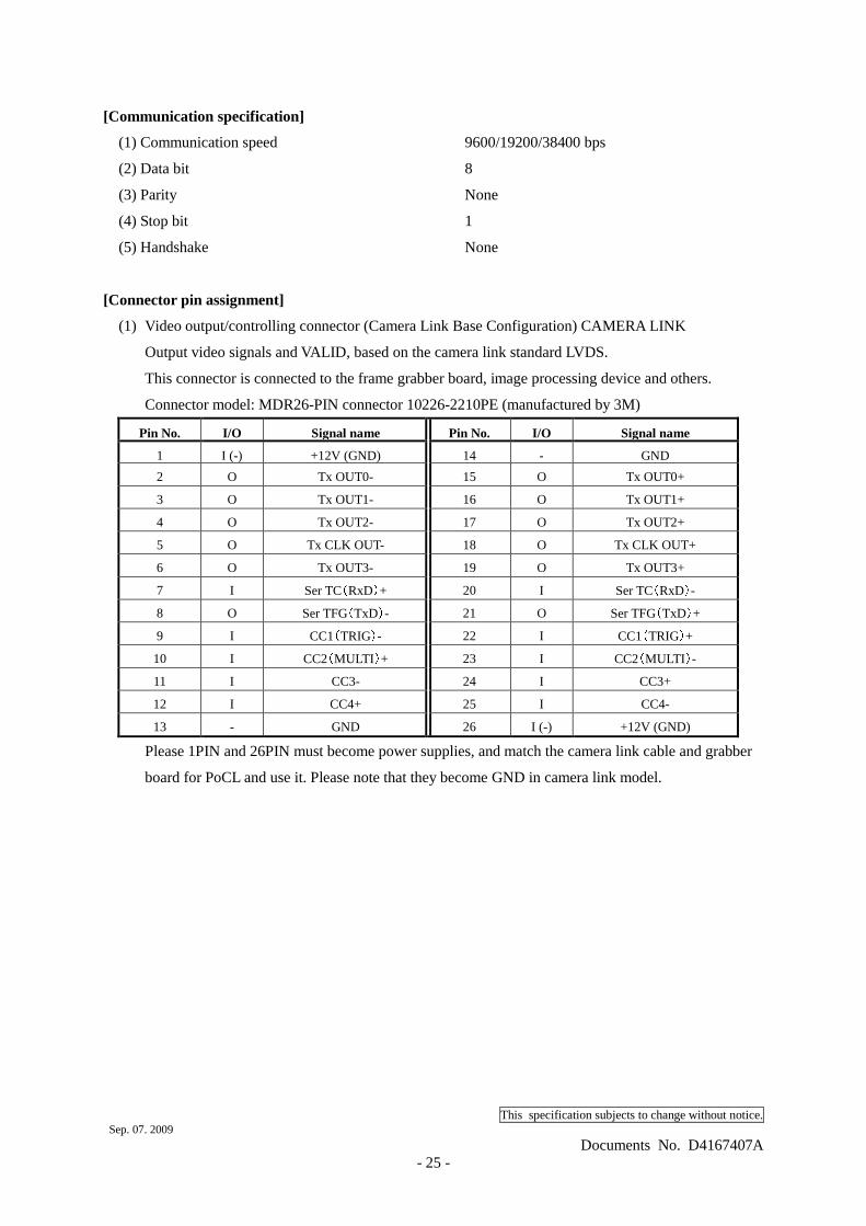
(1) Video output/controlling connector (Camera Link Base Configuration) CAMERA LINK
Output video signals and VALID, based on the camera link standard LVDS.
This connector is connected to the frame grabber board, image processing device and others.
Connector model: MDR26-PIN connector 10226-2210PE (manufactured by 3M)
Pin No. I/O Signal name Pin No. I/O Signal name
1 I (-) +12V (GND) 14 - GND
2 O Tx OUT0- 15 O Tx OUT0+
3 O Tx OUT1- 16 O Tx OUT1+
4 O Tx OUT2- 17 O Tx OUT2+
5 O Tx CLK OUT- 18 O Tx CLK OUT+
6 O Tx OUT3- 19 O Tx OUT3+
7 I Ser TC(RxD)+ 20 I Ser TC(RxD)-
8 O Ser TFG(TxD)- 21 O Ser TFG(TxD)+
9 I CC1(TRIG)- 22 I CC1(TRIG)+
10 I CC2(MULTI )+ 23 I CC2(MULTI )-
11 I CC3- 24 I CC3+
12 I CC4+ 25 I CC4-
13 - GND 26 I (-) +12V (GND)
Please 1PIN and 26PIN must become power supplies, and match the camera link cable and grabber
board for PoCL and use it. Please note that they become GND in camera link model.
This specification subjects to change without notice. Sep. 07. 2009
Documents No. D4167407A - 26 -
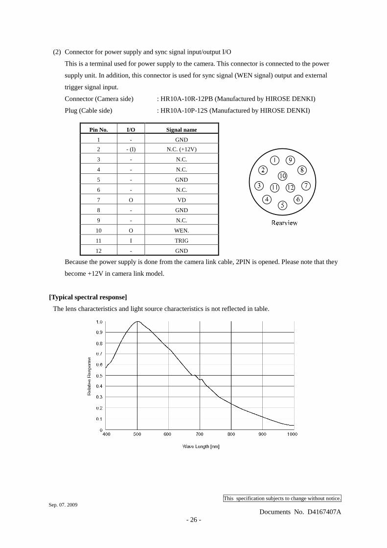
(2) Connector for power supply and sync signal input/output I/O
This is a terminal used for power supply to the camera. This connector is connected to the power
supply unit. In addition, this connector is used for sync signal (WEN signal) output and external
trigger signal input.
Connector (Camera side) : HR10A-10R-12PB (Manufactured by HIROSE DENKI)
Plug (Cable side) : HR10A-10P-12S (Manufactured by HIROSE DENKI) Pin No. I/O Signal name
1 - GND
2 - (I) N.C. (+12V)
3 - N.C.
4 - N.C.
5 - GND
6 - N.C.
7 O VD
8 - GND
9 - N.C.
10 O WEN.
11 I TRIG
12 - GND
Because the power supply is done from the camera link cable, 2PIN is opened. Please note that they
become +12V in camera link model. [Typical spectral response]
The lens characteristics and light source characteristics is not reflected in table.
This specification subjects to change without notice. Sep. 07. 2009
Documents No. D4167407A - 27 -
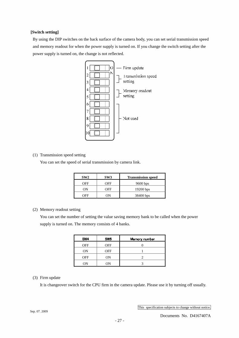
[Switch setting]
By using the DIP switches on the back surface of the camera body, you can set serial transmission speed
and memory readout for when the power supply is turned on. If you change the switch setting after the
power supply is turned on, the change is not reflected.
(1) Transmission speed setting
You can set the speed of serial transmission by camera link.
SW2 SW3 Transmission speed
OFF OFF 9600 bps
ON OFF 19200 bps
OFF ON 38400 bps
(2) Memory readout setting
You can set the number of setting the value saving memory bank to be called when the power
supply is turned on. The memory consists of 4 banks.
SW4SW4SW4SW4 SW5SW5SW5SW5 Memory numberMemory numberMemory numberMemory number OFF OFF 0
ON OFF 1
OFF ON 2
ON ON 3
(3) Firm update
It is changeover switch for the CPU firm in the camera update. Please use it by turning off usually.
This specification subjects to change without notice. Sep. 07. 2009
Documents No. D4167407A - 28 -
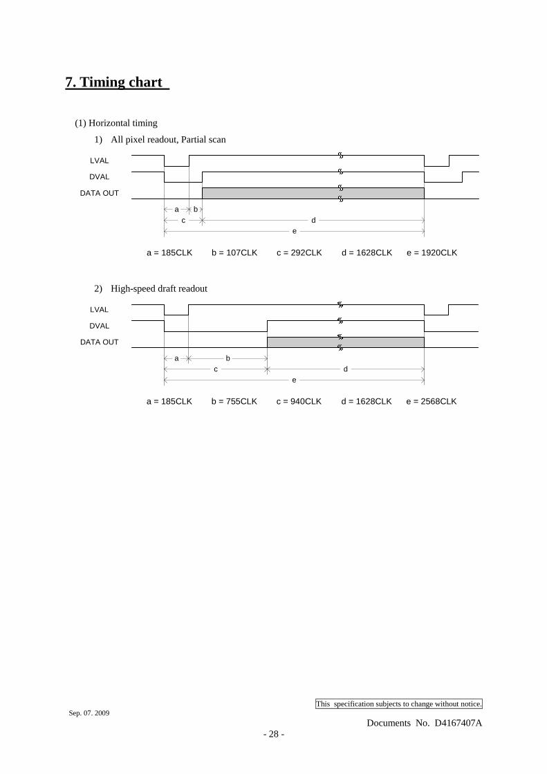
7. Timing chart
(1) Horizontal timing
1) All pixel readout, Partial scan
LVAL
DVAL
a bc d
e
DATA OUT
a = 185CLK b = 107CLK c = 292CLK d = 1628CLK e = 1920CLK
2) High-speed draft readout
LVAL
DVAL
a bc d
e
DATA OUT
a = 185CLK b = 755CLK c = 940CLK d = 1628CLK e = 2568CLK
This specification subjects to change without notice. Sep. 07. 2009
Documents No. D4167407A - 29 -
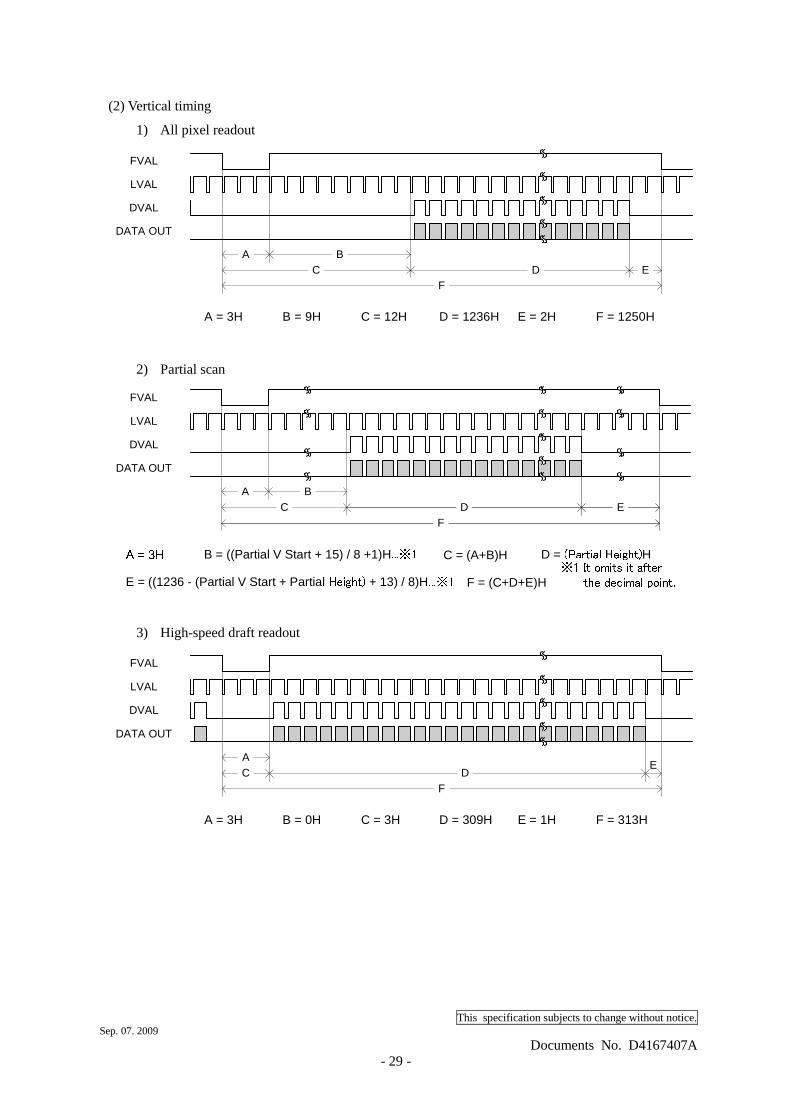
(2) Vertical timing
1) All pixel readout
FVAL
DATA OUT
LVAL
DVAL
AC
BD E
F
A = 3H B = 9H C = 12H D = 1236H E = 2H F = 1250H
2) Partial scan
FVAL
DATA OUT
LVAL
DVAL
AC D
FA = 3H B = ((Partial V Start + 15) / 8 +1)H...※1 C = (A+B)H D = (Partial Height)HF = (C+D+E)H
BE
E = ((1236 - (Partial V Start + Partial Height) + 13) / 8)H...※1 ※1 It omits it after the decimal point.
3) High-speed draft readout
E
FVAL
DATA OUT
LVAL
DVAL
AC D
F
A = 3H B = 0H C = 3H D = 309H E = 1H F = 313H
This specification subjects to change without notice. Sep. 07. 2009
Documents No. D4167407A - 30 -
8. Outline Drawing
This specification subjects to change without notice. Sep. 07. 2009
Documents No. D4167407A - 31 -
9. Guarantee
The term of a guarantee is one year after the product delivery. If by any chance trouble by responsibility
of our company occurs before an above period, TELI repairs it free of charge. During terms of a
guarantee, when the trouble cause is the case of below, TELI charges the repair costs.
(1) Troubles and the damages that causes by misuse, unsuitable repair or remodeling.
(2) Distribution hazards like drops and vibrations after purchase. Troubles and damages by
transportation.
(3) Troubles and damages by fire, natural calamity (earthquake, storm and flood damage, thunderbolt),
damages from salty breeze, gas harm, abnormal voltage.
10. Repair
(1) Condition for repair
Basically, has to return it to our company when the user requests us to repair product.
Beside that, customer should pay these expenses (travel expenses, camera disassembly
Technology costs) of both customer and end user. Also customer should pay in themselves costs
for return camera to us.
(2) The period of repairing product
- Repair free of charge … Refer to Clause 9.
- Charged repair ……….. Basically, repair period is 7 years after the last production end of
products.
This specification subjects to change without notice. Sep. 07. 2009
Documents No. D4167407A - 32 -
Head Office : 7-1, 4 chome, Asahigaoka, Hino-shi, Tokyo, 191-0065, Japan
(International business department)
Phone : +81-42-589-8771
Fax : +81-42-589-8774
URL : http://www.toshiba-teli.co.jp/
Distributor
•This product must be classified for disposal according to the laws of each country and municipal laws.
•Information contained in this document is subject to change without prior notice.