Embed Size (px)
Citation preview

Trans. JSASS Aerospace Tech. JapanVol. 8, No. ists27, pp. Pd_91-Pd_97, 2010
Original Paper
Copyright© 2010 by the Japan Society for Aeronautical and Space Sciences and ISTS. All rights reserved.
Pd_91
High-Speed Attitude Control System for Small Satellite
with Micro-CMGs
By Kyohei AKIYAMA1), Kota FUJIHASHI1) and Saburo MATUNAGA1)
1)Tokyo Institute of Technology ,Tokyo, Japan
(Received July 24th, 2009)
The problem of high-speed maneuver with CMGs (Control Moment Gyros) is considered. In general, CMGs are mostly mounted on large spacecraft, such as ISS (International Space Station) or MIR space station because it is large in size and requires a substantial amount of power. The objective of this paper is to introduce the Micro-CMG, which has been jointly-developed by LSS and TAMAGAWA SEIKI Co., Ltd. This CMG is used to achieve the mission that the small satellite named TSUBAME observes the emission of gamma-ray burst. Furthermore, a time-optimal control problem is solved numerically using the gradient method to obtain the time-optimal input to the pyramid array of four CMGs. The solution gives some indication of the feasibility of the mission of TSUBAME.
Key Words: CMG (Control Moment Gyro), Micro-CMG, TSUBAME, Time-Optimal Control
1. Introduction The Laboratory for Space Systems at the Tokyo Institute of Technology (LSS) has developed and launched three nano- satellites named CUTE-I 1), Cute-1.7 + APD 2) and Cute-1.7 + APD II 3,4), as shown in Fig. 1. These satellites are now in-orbit and strongly transmitting signal to the Earth. These successful satellite projects enabled LSS to acquire the satellite bus technology and demonstrate how students conduct the development of a satellite from the initial concept design phase up to the effective launch and operation.
Based on the acquired technologies, the fourth small satellite project named TSUBAME 5,6) has started. The satellite TSUBAME has a size of 30cm×30cm×30cm and weight of 30kg. The mission of the satellite is observation of polarized gamma-ray by high-speed attitude maneuver with the Micro-CMGs (Control Moment Gyros). This mission sequence is shown in Fig. 2.
The duration of gamma-ray bust is very short. It becomes dark within 60 seconds after the burst occurrence. Therefore, an observation has to be conducted within 10 to 30 seconds and a high-speed maneuver is needed. Thus, the satellite is required to achieve the attitude maneuver by 90 degrees within 15 seconds using Micro-CMGs.
Fig. 1. Three nano-satellites developed in LSS.
1. Burst Occurrence
2. Detection and Position determination
3. High-speed maneuver with Micro-CMGs 4. Start observation
Fig. 2. Mission sequence of the TSUBAME.
CMG is the device that produces torque by changing the
rotation direction of the flywheel supported by the gimbal. The advantage of CMG is the capability to provide large torque compared to a reaction-wheel, which is used in many satellites. However, CMGs are mostly mounted on large spacecraft, such as ISS or MIR because it is, in general, large in size and requires a substantial amount of power. Therefore, it is difficult for small satellites with traditional CMGs to change its attitude at high speed.
This paper details the design and development of Micro-CMG aiming at high speed attitude maneuver and its control and steering logic with a gradient method, which is one of the nonlinear programming methods to solve optimal control problem. 2. Design and Development of Micro-CMG 2.1. Requirement specification for Micro-CMG Some specific requirements for designing Micro-CMG of the TSUBAME are shown as follows.
The satellite mass including the observation equipments is 30 kg. The satellite is required to change its attitude toward the observation direction within 15 seconds after detecting the emission of gamma-ray burst. The satellite is required to achieve the 90 degree maneuver Maneuver trajectory is not considered.
Trans. JSASS Aerospace Tech. Japan Vol. 8, No. ists27 (2010)
Pd_92
Based on these requirements, the performance of Micro-CMG will be considered. The two important factors to design Micro-CMG are the maximum torque and angular momentum. Taking these specific requirements into account, the constraint condition of Micro-CMG is summarized as “Micro-CMG has to meet the requirement to change the satellite’s attitude by 90 degrees within 15 seconds”. From the specific requirements shown above, it can be said that Micro-CMGs have to finish attitude maneuver of 90 degrees within 15 seconds.
It is assumed that the maneuver of satellite is the ideal single axis motion. In case of the satellite maneuver with PD or PID control, the controlling force increases as the maneuver angle becomes large, and exceeds the performance limit of an attitude control actuator. In addition, considering the control bandwidth, the bang-bang control based on the principles of Pontryagin is employed to achieve the maneuver in the shortest period of time.
However, when this control method is used to the satellite maneuvering, it is expected that a great deal of angular momentum is required to Micro-CMG. Therefore, the control scheme which accepts the saturation of angular velocity of a satellite to lessen the maximum angular momentum of the Micro-CMG is adopted instead. The trajectory of this maneuver torque and angular velocity is as shown in Figs. 3 and 4.
In Figs. 3 and 4, it is assumed that the average angular momentum required to the Micro-CMG is 50mNms. To obtain the maximum generated torque and total angular momentum in a typical pyramid array of four CMGs, the index called “maximum average torque” and the maximum angular momentum in the typical pyramid array of four CMGs has introduced as 7)
(1)
(2) where is maximum average torque and is total angular momentum. Moreover, h and is angular momentum per unit CMG and maximum gimbal rate of a CMG. Then, the total angular momentum of this CMG system becomes
[ ]Nmshh 158.0050.016.316.3max =×=×= (3)
Fig. 3. (left) Trajectory of the ideal maneuver torque. Fig. 4. (right) Trajectory of the ideal angular velocity of the satellite.
Assuming that the moment of inertia of the satellite is a diagonal matrix, the rotation of a rigid body satellite is described by Euler’s equation of motion as follows.
( ) TIωωωI =×+& (4)
hIω = (5)
(6) Furthermore, assuming the ideal single axis motion around X-axis, then angular velocity of the satellite is described as
[ ]Tx 00ω=ω and the rotational motion is simplified as follows.
xx TωI =& (7)
xxxx hωI = (8)
Consequently, the following equation shows the maximum angular velocity of the satellite with the Micro-CMGs system on the condition that the principle moment of inertia of TSUBAME is 1.0 kgm2.
[ ]sradI
hωxx
158.00.1
158.0maxmax === (9)
Defining the acceleration time in terms of Δt, the relation between the maneuver angle and maximum angular velocity of the satellite is given as follows. (10) From this equation, 5.1 sec of acceleration time is required to change the satellite’s attitude by 90 degrees within 15 seconds and then angular acceleration is calculated to be 0.031rad/s2. Thus, maximum generated torque in a typical pyramid array of four CMGs is calculated as follows.
[ ] [ ]mNmNmωIT xxx
31031.0031.00.1max
≅=×== &
(11)
Referring to the maximum average torque, maximum gimbal rate of the CMG is calculated as follows.
49.0
031.028.1
max
maxmax
>
>×=
δ
δ&
&hT (12)
Thus, the CMG is required to have no less than 0.49 rad/s of maximum gimbal rate in case that the average angular momentum requirement of the Micro-CMG is 50 mNms. Based on these requirements, the performance demand of Micro-CMG is given as follows. (13)
⎥⎥⎥
⎦
⎤
⎢⎢⎢
⎣
⎡=
zz
yy
xx
II
I
000000
I
( ){ } ( )ttωtttωΔ−=
Δ−+= max
max
22θ
[ ][ ]Nmsh
srad050.0
50.0max
==δ&
maxmax 28.1 δ&hT ×=
hh ×= 16.3max
maxT maxh
-0.04-0.03-0.02-0.01
00.010.020.030.04
0 5 10 15
Torq
ue [N
m]
Time [s]0
0.020.040.060.080.1
0.120.140.160.18
0 5 10 15
Ang
ular
Vel
ocity
[r
ad/s]
Time [s]
maxδ&
K. AKIYAMA et al.: High-Speed Attitude Control System for Small Satellite with Micro-CMGs
Pd_93
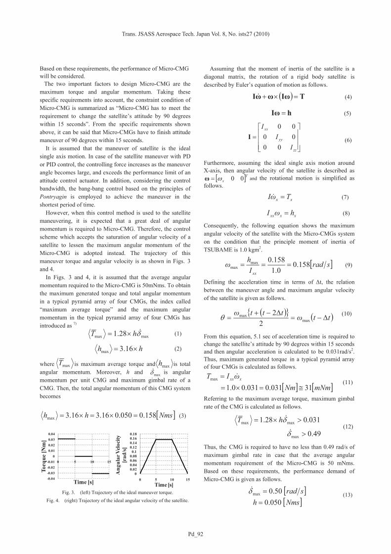
2.2. The detail of Micro-CMGs system The Micro-CMG shown in Fig. 5 has been jointly-developed by LSS and TAMAGAWA SEIKI Co., Ltd to achieve the mission, the observation of gamma-ray burst. This CMG is for a small satellite that achieves high-speed maneuver to reduce the size and weight while filling all performance demands. This section details the system of the Micro-CMG. In this section, the detail of the Micro-CMG system is introduced. The Micro-CMG is designed to produce the required torque with a typical pyramid array of four CMGs, the common configuration of CMGs. The CMG wheel is 33 mm in diameter and the length is 134 mm including the motor in gimbal system. The basic specifications of the Micro-CMG are shown in Table 1.
The features of the Micro-CMG, shown in Fig. 5, are that the wheel, gimbal and gimbal angle sensor of the CMG are hermetically sealed in a cylindrical structure and the total mass is less than 1.0 kg. A simple system block diagram of the Micro-CMG is shown in Fig. 6.
The Micro-CMG wheel, shown in Fig. 7 (a), has 209.67 gcm2 of moment of inertia about the center of rotation to meet the performance requirement of the angular momentum. The motor steering the CMG wheel is a hysteresis synchronous motor developed by TAMAGAWA SEIKI Co., Ltd and its rotational speed can reach 24000 rpm in the steady state.
The CMG gimbal, shown in Fig. 7 (b), is driven by a hybrid-type step motor (TS3692N1) made by TAMAGAWA SEIKI Co., Ltd. This motor has the unipolar connection and driven by the biphasic pulse.
Fig. 5. Overview images of the Micro-CMG.
Table 1. Micro-CMG property. Size φ50×134 mm Wight 960 g Wheel inertia 209.67 g cm2
Angular momentum(nominal) 0.0527 N m sec Gimbal angle rate(maximum) ±1.0 rad/sec Synchronous motor (Wheel) 0.2 Arms / 26V 400Hz Step motor (Gimbal) 0.35 A / 3.5V Angle sensor (Gimbal) 200 mA / 5V DC
Fig. 6. System chart of the Micro-CMG.
(a) Wheel (b) Gimbal
Fig. 7. Image of the Micro-CMG system. In order to control and drive the CMG gimbal motor, the gimbal angle, defined as a displacement angle from the initial position, must be measured at any time. Therefore, the Micro-CMG has a contactless positional encoder, AE8001, made by Asahi Kasei EMD Corporation for gimbal angle measurement. This sensor can measure the rotational angle by detecting the change of magnetic field in the gimbal rotor with a specific hall element. The rotational angle measured by the gimbal angle sensor is stored in a memory through an A/D converter. 2.3. Frequency-response measurement Frequency-Response Method is one of the most commonly used techniques for feedback control system analysis and design. This method is the expression for the control plant property by measuring its gain and phase of input sine or cosine wave. The frequency responses of the Micro-CMG wheel and gimbal systems are measured to decide attitude control bandwidth of the satellite. The input and output signals are measured as a function of the frequency of the AC power line and rotational speed of the CMG wheel, respectively. Furthermore, frequency responses are used to express the property of the CMG wheel and gimbal. Figs. 8 (a) and (b) show the measured frequency response of the CMG wheel and gimbal. The driving voltage of the CMG wheel has been 35V (RMS value). As shown in Fig. 8 (a), the gain in wheel system decreases as the frequency of the AC power line is increased and its decline starts from about 0.05 Hz of input frequency. These results imply a performance degradation of the wheel system. In order to design a control
Trans. JSASS Aerospace Tech. Japan Vol. 8, No. ists27 (2010)
Pd_94
system, it is common to identify the frequency at which the system gain decreases by 3 dB as a control bandwidth. Based on this scheme, the bandwidth of wheel system is 0.2 Hz and the control bandwidth of the satellite should be low enough.
On the other hand, the result of the gimbal system shown in Fig. 8 (b) has the same trend as that of the wheel system, but gain and phase decrease gradually. Note that the vertical scale on Figs. 8 (a) and (b) is different and the gain decreases very little even in the frequency of 1.0 Hz.
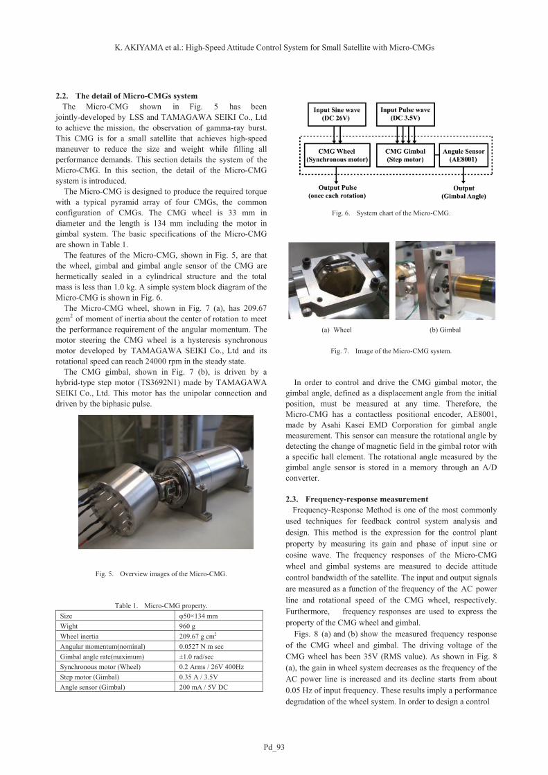
According to the measured frequency-response of the wheel and gimbal systems, the control bandwidth of the Micro-CMG wheel has to be set to less than 0.2 Hz when the Micro-CMG is used as a VSCMG (Variable Speed CMG). In addition, the control bandwidth of the satellite has to be ten times lower than that of the Micro-CMG wheel. 2.4. Electrical requirement It is desired to decrease the power consumption of the Micro-CMG as much as possible. Thus, optimum driving voltage, at which power consumption of the Micro-CMG becomes at a minimum in steady rotational speed of the wheel, has been measured. In this experiment, four different driving voltages (RMS value) 24V, 26V, 30V and 36V, has been used in each measurement and the average power consumption at the steady state has been measured. Furthermore, these measurements are iterated varying the rotational speed of the CMG wheel between 320 Hz (19200 rpm) and 460 Hz (27600 rpm). It leads to find the relations between the average power consumption and the rotational speed of the CMG wheel in
each driving voltage as shown in Fig. 9. According to Fig. 9, the average power consumption of the
wheel motor decreases as the wheel rotational speed is increased in each experiment. Because CMG wheel is driven by a hysteresis synchronous motor and its synchronous speed is set to 24000 rpm. In addition, Fig. 9 shows that the system has the minimum power consumption at the driving voltage of 24V. However, CMG wheel cannot reach the required rotational speed, 24000rpm.
Thus, under the condition that the Micro-CMG wheel rotates steadily in 24000 rpm, 26V is the optimal voltage to be applied to minimize the average power consumption, and then the minimum power consumption is approximately 3.5 W in the Micro-CMG wheel excluding the gimbal part. It would appear that this power consumption small enough to be generated by a small satellite such as TSUBAME 3. Time Optimal Control Logic for TSUBAME As the solution of the control problem of a spacecraft with CMGs, many control and driving theories of CMGs have been proposed, and one should choose the method properly depending on the mission requirement of the satellite. In case of TSUBAME, a feed-forward control is employed in order to minimize the maneuver time. In this control, the trajectory of control input is optimized in advance. It is, however, very difficult to solve the optimal control problem when the control system is nonlinear or the control input is the “bang-bang control”, which controls the switch abruptly between two states. In cases like that system, “iterative calculation method” is commonly used to calculate optimal control problem of nonlinear system. In this method a nominal control value is provided and revised by iterated calculation. Then the solution is determined based on the convergence result. This section deals with the optimal control problem of the satellite used with “gradient method”, which is one of iterative calculation methods to solve nonlinear optimal control problem. In this method, it is required to figure out how the final state has changed as the input changes.
(b) Gambal
Fig. 8. Frequency-response in the Micro-CMG.
Fig. 9. Average power consumption with the rotational speed of the Micro-CMG wheel.
(a) Wheel
-1
-0.5
0
0.5
0.01 0.1 1
Gai
n[d
B]
-80
-60
-40
-20
0
20
0.01 0.1 1
Phas
e[d
eg]
Frequency [Hz]
2
3
4
5
6
7
8
9
10
18000 20000 22000 24000 26000 28000 30000
Pow
er (A
ve) [
W]
Wheel Spin speed [rpm]
24V 26V 30V 36V
-15
-10
-5
0
5
0.01 0.1
Gai
n[d
B]
-100
-50
0
50
0.01 0.1
Phas
e[d
eg]
Frequency [Hz]
K. AKIYAMA et al.: High-Speed Attitude Control System for Small Satellite with Micro-CMGs
Pd_95
3.1. Time-optimal control with gradient method Consider the cost function as follows.
( ){ } )1(''1
0
Ψ+−−+= ∫ ντdpVxfpVLpJ px (14)
where p is a scale parameter. Now, introduce Hamiltonian and the gradient function W(τ), which is a function of time τ. The cost function is given as follows.
{ } )1(''''1
0
Ψ+−+−−= ∫ ντνν dWWpVxVHJ px (15)
The gradient function is assigned to this formulation. Performing integration of the last integral term, we obtain
{ } )1()0()1('''1
0
Ψ++−+−−= ∫ ννντν WWdWpVxVHJ px (16)
Taking the variation of J and choosing undetermined multipliers as follows,
0)1(;' =−= xxx VHV
)1()1(;' xxxxx WpfWW Ψ=−=
0)1(;' =−= ppp VHV (17)
[ ] )1()1(;' pppxp WfpfWW Ψ=+−=
Then, the variation of J is given as follows.
( ) { } )0()0()0(1
0
pWVdupfWHJ ppuxu δντδνδ +++= ∫ (18)
Furthermore, choosing δu and δp as follows,
( )pfWHu uxu νδ +−= (19)
( ) ( )( )00 pp WVp νδ +−= (20)
These conditions ensure that the cost function reduces gradually.
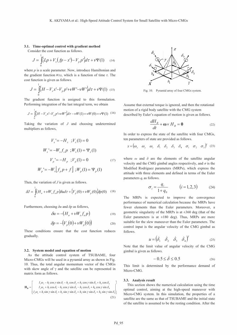
3.2. System model and equation of motion As the attitude control system of TSUBAME, four Micro-CMGs will be used in a pyramid array as shown in Fig. 10. Thus, the total angular momentum vector of the CMGs with skew angle of γ and the satellite can be represented in matrix form as follows.
⎥⎥⎥
⎦
⎤
⎢⎢⎢
⎣
⎡
+++++−−+
++−−=
44332211
44332211
44332211
sinsinsinsinsinsinsinsinsincoscossincoscoscossincoscossincos
δγδγδγδγωδγδδγδωδδγδδγω
hhhhIhhhhI
hhhhI
zz
yy
xx
BH
(21)
Assume that external torque is ignored, and then the rotational motion of a rigid body satellite with the CMG system described by Euler’s equation of motion is given as follows.
0ω =×+ BB H
dtdH
(22)
In order to express the state of the satellite with four CMGs, ten parameters of state are provided as follows.
( )Tzyxx 3214321 σσσδδδδωωω= (23)
where ω and δ are the elements of the satellite angular velocity and the CMG gimbal angles respectively, and σ is the Modified Rodriguez parameters (MRPs), which express the attitude with three elements and defined in terms of the Euler parameters qi as follows.
( )3,2,11 0
=+
= iq
qiiσ (24)
The MRPs is expected to improve the convergence performance of numerical calculation because the MRPs have fewer elements than the Euler parameters. Moreover, a geometric singularity of the MRPs is at ±360 deg (that of the Euler parameters is at ±180 deg). Thus, MRPs are more suitable for the slew maneuver than the Euler parameters. The control input is the angular velocity of the CMG gimbal as follows.
( )Tu 4321 δδδδ &&&&= (25)
Note that the limit value of angular velocity of the CMG gimbal is given as follows.
5.05.0 ≤≤− δ& (26)
This limit is determined by the performance demand of Micro-CMG. 3.3. Analysis result This section shows the numerical calculation using the time optimal control, aiming at the high-speed maneuver with Micro-CMG system. In this simulation, the properties of a satellite are the same as that of TSUBAME and the initial state of the satellite is assumed to be the resting condition. After the
Fig. 10. Pyramid array of four CMGs system.
Trans. JSASS Aerospace Tech. Japan Vol. 8, No. ists27 (2010)
Pd_96
maneuver, the satellite is satisfied with the terminal condition as shown in eq. (28). In other words, the final state of the satellite is the resting condition and the attitude is the same one after a satellite changes its attitude by 90 degrees around Y-axis. The Initial Condition
[ ] [ ] 0)(0
32143210 ===
=T
zyxtt
x σσσδδδδωωωφ
(27) The Terminal Condition
[ ] 0
414.0321
)(
3
2
1
3
2
1
=
⎥⎥⎥⎥⎥⎥⎥⎥
⎦
⎤
⎢⎢⎢⎢⎢⎢⎢⎢
⎣
⎡
−
=
⎥⎥⎥⎥⎥⎥⎥⎥
⎦
⎤
⎢⎢⎢⎢⎢⎢⎢⎢
⎣
⎡
−−−−−−
=
==
=
ff
f
Tt
z
y
x
Tt
zfz
yfy
xfx
Tt
MRPMRPMRP
x
σσ
σωωω
σσσ
ωωωωωω
ψ (28)
The Assessment Function
f
TTdtJ f == ∫0 (29)
The terminal time should be considered in the assessment function because minimum time maneuver is required. Thus, in this optimal control problem, the time of the terminal condition Tf should be calculated as an unknown parameter. This program, however, can deal with the parameter Tf within a range of 0 to 1. Therefore, in order to normalize the time, a new parameter is defined as follows.
( )10 ≤≤≡ ττfT
t (30)
The time derivative of the parameter τ is given by
fTdtd 1
=τ
(31)
Taking this normalization of the time, the equation of state in this problem is written as follows.
( )puxTddx
F ,,f×=τ
(32)
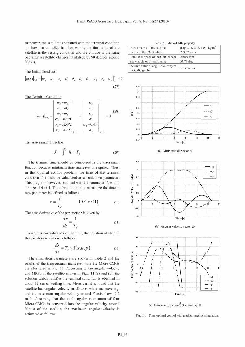
The simulation parameters are shown in Table 2 and the results of the time-optimal maneuver with the Micro-CMGs are illustrated in Fig. 11. According to the angular velocity and MRPs of the satellite shown in Figs. 11 (a) and (b), the solution which satisfies the terminal condition is obtained in about 12 sec of settling time. Moreover, it is found that the satellite has angular velocity in all axes while maneuvering, and the maximum angular velocity around Y-axis shows 0.2 rad/s. Assuming that the total angular momentum of four Micro-CMGs is converted into the angular velocity around Y-axis of the satellite, the maximum angular velocity is estimated as follows.
Table 2. Micro-CMG property. Inertia matrix of the satellite diag[0.73, 0.73, 1.04] kg m2
Inertia of the CMG wheel 209.67 g cm2 Rotational Speed of the CMG wheel 24000 rpm Skew angle of pyramid array 54.75 deg the limit value of angular velocity of the CMG gimbal
±0.5 rad/sec
-0.05
0
0.05
0.1
0.15
0.2
0.25
0.3
0.35
0.4
0.45
0 2 4 6 8 10 12 14
MR
P
Time [s]
σ1
σ2
σ3
(a) MRP attitude vector σ
-0.1
-0.05
0
0.05
0.1
0.15
0.2
0.25
0 2 4 6 8 10 12 14Ang
ular
Vel
ocity
[rad
/s]
Time [s]
ωxωy
ωz
(b) Angular velocity vector ω
-0.6
-0.4
-0.2
0
0.2
0.4
0.6
0 2 4 6 8 10 12 14
Gim
bal S
peed
[rad
/s]
Time [s]
u1u2u3u4
(c) Gimbal angle ratesδ& (Control input)
Fig. 11. Time-optimal control with gradient method simulation.

K. AKIYAMA et al.: High-Speed Attitude Control System for Small Satellite with Micro-CMGs
Pd_97
]/[205.073.0
05.04maxmax
sradIH
y
CMGyy ≈
×==ω (33)
This result is almost the same value of the maximum angular velocity shown in Fig. 11 (b). Thus, it can be said that angular momentum is used effectively in this simulation. 4. Conclusion
This paper presents the Micro-CMGs, which is enough small and consumes little power so that it would be mounted on a small satellite like TSUBAME. The CMG wheel is 33 mm in diameter and the length is 134 mm including the motor in gimbal system. The average power consumption of the CMG wheel is about 3.5 W.
Furthermore, time-optimal control problem for the pyramid array of four CMGs has been solved numerically using the gradient method. The solution has been obtained in about 12 sec of settling time, which achieves a high speed attitude maneuver for TSUBAME by 90 degrees within 15 seconds using Micro-CMGs. This result gives some indication of the feasibility of the TSUBAME development.
References 1) Nakaya, K., Konoue, K., Sawada, H., Ui, K., Okada, H., Miyashita,
N., Iai, M., Urabe, T., Yamaguchi, N., Kashiwa, M., Omagari, K., Morita, I. and Matunaga, S.: Tokyo Tech CubeSat: CUTE-I - Design & Development of Flight Model and Future Plan -, AIAA 21st International Communications Satellite Systems Conference and Exhibit, Yokohama, 2003, AIAA 2003-2388.
2) Miyashita, N., Iai, M., Omagari, K., Imai, K., Yabe, H., Miyamoto, K., Iljic, T., Usuda, T., Fujiwara, K., Masumoto, S., Konda, Y., Sugita, S., Yamanaka, T., Konoue, K., Ashida H. and Matunaga, S.: Development and Flight Report of Pico-Satellite Cute-1.7 + APD, ists25(2006), 2006-f-08.
3) Maeno, M., Omagari, K., Iljic, T., Masumoto, S., Fujiwara, K., Konda, Y., Yamanaka, T., Tanaka, Y., Ueno, T., Ashida, H., Nishida, J., Hagiwara, Y., Fujihashi, K., Ikeda, T., Inagawa, S., Miura, Y. and Matunaga, S.: Development of Tokyo Tech Nano-Satellite Cute-1.7 + APD II, The 17th Workshop on JAXA Astrodynamics and Flight Mechanics, Sagamihara, 2007.
4) Ashida, H., Nishida, J., Omagari, K., Fujiwara, K., Konda, Y., Yamanaka, T., Tanaka, Y., Maeno, M., Fujihashi, K., Inagawa, S., MIURA Y. and Matunaga, S.: Flight Model Development of Tokyo Tech Nano-Satellite Cute-1.7 + APD II, ists26(2008), 2008-f-22.
5) Junichi Nishida, Yoshihiro Tsubuku: Tokyo Tech’s Technology Demonstration Satellite “TSUBAME”, 21st Annual Conference on Small Satellite Student Competition, Utah, 2007.
6) Fujihashi, K., Omagari, K. and Matunaga, S.: Science and Technology Demonstration Satellite “TSUBAME” and its attitude Control System Using Micro CMGs, ists26(2008), 2008-d-48.
7) Omagari, K., Fujihashi, K. and Matunaga, S.: CMG Configuration and Control for Rapid Attitude Maneuver of Small Spacecraft, 9th International Symposium on Artificial Intelligence, Robotics and Automation in Space, Los Angeles, CA, 2008.


![Satellite Attitude Control Using Three Reaction Wheels · Satellite attitude control using three reaction wheels ... [12]. A reaction wheel is a device that applies torque ... The](https://img.pdfslide.net/doc/110x75/5b885d727f8b9abf5c8b699b/satellite-attitude-control-using-three-reaction-satellite-attitude-control-using.jpg)