Embed Size (px)
Citation preview

Athens Journal of Technology and Engineering - Volume 6, Issue 3 – Pages 141-162
https://doi.org/10.30958/ajte.6-3-1 doi=10.30958/ajte.6-3-1
High Strength Concrete Tests under Elevated
Temperature
By Zhuoya Wu*, Sai Huen Lo
†, Kang Hai Tan
‡ &
Kai Leung Su♦
In recent years, application of high strength concrete (HSC) has attracted increasing
interest in the construction industry due to its significant economic, architectural, and
structural advantages, compared to the conventional normal strength concrete (NSC).
However, under fire condition, which is one of the most common hazards that attack
building structures, HSC members may be subjected to explosive spalling. Strength
reduction of structural members may occur, leading to severe consequences such as
failure of members or even collapse of the whole structure. A newly designed 2-
layered cylindrical specimen consisting of an HSC core and an NSC outer layer is
proposed to improve the fire performance of HSC members under elevated
temperature. The NSC layer is designed to act as an outer layer insulation to reduce
the thermal gradient and also serve as a lateral confinement to prevent the HSC core
from spalling. Compression and thermal tests were performed on the specimens to
investigate their strength and behavior under elevated temperature. Test results
preliminarily verify the feasibility of 2-layered design and at the same time provide
insights for the applicability of 2-layered columns in practical construction projects.
Keywords: 2-Layered Specimens, Elevated Temperature, High Strength Concrete,
Normal Strength Concrete, Spalling.
Introduction
High strength concrete (HSC), as one of the most widely used construction
materials, gains increasing popularity in the recent years due to the upsurge of
high-rise buildings, long-span bridges and tunnels. Compared to the normal
strength concrete (NSC), HSC has advantages in not only the structural but also
the economic and aesthetic aspects. When applied in buildings, HSC is commonly
used as structural members such as beams, columns and slabs, which function
as the load bearing elements. It is therefore of particular importance to make
sure that the high strength concrete members could survive from those extreme
environmental conditions, among which fire has aroused primary concerns due
to the spalling of HSC when exposed to elevated temperatures. Spalling refers
to the breaking away of surface layers (pieces) of concrete from the structural
elements exposed to high and rapidly rising temperatures, and the explosive
spalling occurs in a more sudden and violent manner (Kodur 2000, Phan 2008).
Though there is no one mechanism that can fully interpret this phenomenon, it
*PhD Student, The University of Hong Kong, China.
†Professor, The University of Hong Kong, China.
‡Professor, Nanyang Technological University, Singapore. Associate Professor, The University of Hong Kong, China.

Vol. 6, No. 3 Wu et al.: High Strength Concrete Tests under Elevated Temperature
142
is believed by the majority that due to the high compactness (low porosity) of
HSC, water vapor pressure trapped inside the concrete could induce spalling
when the pore pressure gradually builds up and exceeds the tensile strength of
concrete under elevated temperatures (Dwaikat and Kodur 2009, Phan 2002,
Kodur et al. 2004, Ichikawa and England 2004, Ozawa et al. 2012, Kalifa et al.
2000, Mindeguia et al. 2010b).
Considering the fact that spalling usually occurs in depth of 10-50mm
from the concrete surface (Jeongwon et al. 2011), this study presents a newly
designed 2-layered (2L) cylindrical specimen consisting of an HSC core and an
NSC outer layer to mitigate the effect of spalling. The NSC layer is designed to
act as an outer layer insulation to reduce the thermal gradient and also as a
lateral confinement to prevent the HSC core from spalling. Although fiber-
reinforced HSC is one of the most commonly used method to mitigate spalling,
drawbacks still exist. For concrete reinforced with polypropylene (PP) fiber,
elastic modulus and compressive strength of the concrete are reduced (Wang et
al. 2019, Jalasutram et al. 2017). For concrete reinforced with steel fiber,
Zheng et al. (2018) pointed out the traditional mixing method could lead to the
non-uniform distribution of steel fiber, mechanical properties of the concrete
would therefore be affected. Chaichannawatik et al. (2018) found that the
addition of fibers in the concrete would reduce the workability of the fiber-
reinforced concrete. On account of the lower workability, reduced compressive
strength and difficulty of uniform mixing on site, it is necessary to implement
the proposed 2-layered design.
Literature Review
Studies on the effects of high temperature on the mechanical properties of
HSC could trace back to as early as the 1980s. Among these early studies were
mostly material tests (Felicetti et al. 1996, Furumura et al. 1995, Sullivan and
Sharshar 1992, Hammer 1995, Diederichs et al. 1988, Hertz 1992, Hertz 1984,
Castillo and Durrani 1990) and element tests (Diederichs et al. 1995, Hansen
and Jensen 1995, Sanjayan and Stocks 1993, Shirley et al. 1988). There were
also some other early studies that adopted different techniques, for instance, the
scanning electron microscopy and stiffness damage test to evaluate the properties
and behavior of HSC at elevated temperatures (Lin et al. 1996, Nassif et al. 1995).
Castillo and Durrani (1990) investigated the compressive strength and load-
deformation relationship of HSC exposed to high temperature by conducting
stressed and unstressed tests on cylinders made of high strength and normal
strength concrete mixtures. Hertz (1984) and Hertz (1992) examined the effect of
temperature, cylinder size and dosage of steel fibers on the compressive
strength, elastic modulus and explosion behavior of silica-fume HSC and
lightweight concrete. Diederichs et al. (1988) studied the material properties as
well as the specimen shape and heating rate by performing unstressed tests,
transient creep and relaxation tests on the specimens of three HSC with different
mineral additions (blast furnace slag, silica fume and fly ash). Hammer (1995)

Athens Journal of Technology & Engineering September 2019
143
observed a typical “breakpoint” at around 300℃ in the strength-temperature
curves, where an explosive failure may occur followed by the release of steam.
Sullivan and Sharshar (1992) concluded that aggregate type could significantly
affect the residual strength of concrete subjected to high temperature. Furumura
et al. (1995) noted that in the unstressed tests there was a compressive strength
recovery to ambient strength at 200℃, which is not observed in the unstressed
residual strength tests. Felicetti et al. (1996) performed unstressed residual
strength tests on the HSC cylinder specimens and the test results revealed
similar trends of reductions in compressive strength and elastic modulus as
observed in other experimental studies mentioned above. Noumowe et al.
(1996) conducted unstressed residual tests on NSC and HSC specimen. Results
showed that both tensile strengths decreased similarly and almost linearly with
increasing temperatures and NSC would become more porous than HSC as
temperatures increased beyond 120℃.
Three series of reinforced and prestressed concrete beam tests were
performed in the research of Hansen and Jensen (1995), which showed that
beams with fibers and protective coating were less suspected to spalling.
Observations from the full scale T-beams fire tests by Sanjayan and Stocks
(1993) reported HSC possesses a higher possibility of spalling in a fire than
NSC and the drying rate of HSC is slower than NSC indicated by its higher
moisture content. The report by Diederichs et al. (1995) summarized results
from three column tests and indicated that the use of fibers to form capillary
can help reduce the risk of spalling in HSC columns and also suggested that
further researches may study the effects of various fiber contents. Shirley et al.
(1988) conducted fire tests on HSC slab and concluded that the fire endurance
of HSC and NSC had no significant difference and none of the specimens
experienced any spalling or explosive behavior.
The one problem that early studies commonly address is the spalling or
explosive behavior of HSC at elevated temperatures, though inconsistencies are
also observed from the test results. While some researchers reported spalling
phenomenon in HSC structural members, there were a few experimental
studies showing little or no obvious spalling. Possible reason for this
conflicting picture on the occurrence of spalling may attribute to the massive
number of factors that affect spalling and their interdependency. To better
understand the behavior and mechanism of HSC under elevated temperature,
and to satisfy the fire safety requirements in practical construction projects,
more recent researches has been done regarding the fire resistance of HSC.
Mechanisms of Spalling
The spalling pattern of HSC could be classified as minor, moderate and
severe (explosive), according to the extent of spalled concrete. Spalling refers
to the breaking away of surface layers (pieces) of concrete from the structural
elements exposed to high and rapidly rising temperature, and the explosive
spalling occurs in a more sudden and violent manner (Phan 2008, Kalifa et al.
2000, Phan and Carino 2002, Kodur 2000). In cases of severe spalling, it is

Vol. 6, No. 3 Wu et al.: High Strength Concrete Tests under Elevated Temperature
144
very likely that the reinforcement would be directly exposed to heat, and therefore
loss of load bearing capacity of structural members may occur, leading to severe
consequences such as failure of members or even collapse of the whole
structure. A review of literature shows that there are mainly three mechanisms
that could account for the spalling phenomenon of HSC (Kodur 2000, Kodur et
al. 2004, Jeongwon et al. 2011, Ozawa et al. 2012, Phan 2002).
Thermal-Mechanical Spalling
When concrete is heated under fire, thermal stress develops due to restrained
thermal expansion. When tensile stress reaches some critical values, vertical
cracks will form between the concrete core and concrete cover (Gawin et al.
2003). If a driving force, such as axial compression, bending stress, or thermal
expansion of concrete is applied, thermal-mechanical spalling happens.
According to the studies conducted from the aspect of thermal stress, the
critical factor influencing the thermal expansion is coarse aggregate (Jeongwon
et al. 2011), and the presence of carbonate aggregate could help improve the
fire endurance of HSC other than the siliceous aggregate (Kodur et al. 2003).
In general, thermal-mechanical spalling occurs when the compressive strength
of concrete is exceeded at the cover. A schematic diagram of thermal-
mechanical spalling of a concrete column is depicted in Figure 1.
Figure 1. Schematic Diagram of Thermal-Mechanical Spalling (Kodur 2000)
Thermal-Hydro Spalling
High strength concrete is made by lowering the water/cement ratio and

Athens Journal of Technology & Engineering September 2019
145
adding some ultra-fine materials such as silica fume that can increases the strength
of the cement-aggregate bond. Superplasticizers are also commonly added to the
high strength mixes in order to compensate for the reduced workability. When
concrete is heated under elevated temperature, liquid water inside the concrete will
become vapor. Due to the low permeability (compact) nature of HSC, the vapor
cannot escape the concrete, leading to the gradual build-up of pore pressure around
the concrete surface. At 300°C, the pore pressure could approximately reach 8MPa
(Kodur 2000, Kodur et al. 2004). The tensile strength of concrete is much lower
than its compressive strength, when concrete could not resist the induced pore
pressure, spalling occurs. At the time of spalling, the pore pressure roughly equals
to the saturated vapor pressure (SVP) (Mindeguia et al. 2010a, Kalifa et al. 2000).
A schematic diagram of thermal-hydro spalling of a concrete column is depicted in
Figure 2. It is reported by Hertz (2003) that low water content by weight (3-4% or
less) could reduce the possibility of spalling in concrete, a phenomenon that
cannot be solely explained by the thermal-mechanical spalling theory, and is
deemed to be mainly affected by the water vapor pressure (pore pressure).
Thermal-hydro spalling, occurring at early stage of heating and with fierce spalling
process, is therefore considered as the most critical spalling by the majority of
researches, though it is still difficult to conclude an exact mechanism to fully
interpret the phenomenon of fire induced spalling in HSC based on the state-of-the
art (Khaliq and Kodur 2011, Khaliq and Kodur 2013, Phan and Carino 1998, Phan
and Carino 2002, Jeongwon et al. 2011, Ozawa et al. 2012).
Figure 2. Schematic Diagram of Thermal-Hydro Spalling (Kodur 2000)
Water vapor pressure is closely connected to the heat or moisture transfer in
concrete, which is strongly affected by the moisture conditions with concrete, and
the effect is particularly strong in a high-temperature environment (Jeongwon et
al. 2011). Measurement of heat/moisture transfer and pressure build-up is of

Vol. 6, No. 3 Wu et al.: High Strength Concrete Tests under Elevated Temperature
146
great difficulties due to the restricted test conditions and the nature of the measured
experimental process. However, development of new experimental methods
accompanied by the progress in the test apparatus has promoted a few
experimental and analytical studies on heat conduction, moisture transfer and pore
pressure build-up (Kalifa et al. 2000, Zdeněk and Werapol 1979, Bažant et al.
1982, Ahmed and Hurst 1999, Phan 2008, Ichikawa and England 2004, Dwaikat
and Kodur 2009, Phan 2002), though most of the pore pressures investigated are in
one direction only. The experimental studies pay special attention to the data from
the proximity of concrete surfaces reasoning the fact that spalling take place
primarily in the range of 10-50mm depth from surface (Jeongwon et al. 2011).
Thermal-Chemical Spalling
Thermal chemical spalling consists of two types of spalling, namely,
sloughing-off spalling at extremely high temperature and post cooling spalling
after exposing to elevated temperature (Xing et al. 2011). The main cause of
thermal-chemical spalling is the break-down of aggregate cement bond, such as
calcium silicate hydroxide and calcium hydroxide (Schneider 1988). Since the
threshold temperature of thermal-chemical spalling is relatively high at around
750℃, it is considered to be the least critical among the three mentioned
spalling. The temperature of thermal-chemical spalling is shown in Figure 3.
Figure 3. Temperature Range of Thermal-Mechanical Spalling
Experimental Studies
Test Specimens
Two identical groups, one for compression tests and the other for fire tests,
of totally 12 cylindrical specimens are designed, within each group, three HSC
and three 2L specimens are prepared. No thermal couples are needed for the
compression tests; therefore, thermal couples are only added in the group for
fire tests, locating at middle height of all specimens. Thermal couples are
placed in a perpendicular way as shown in Figure 4. The detailed dimensions
of specimens can be found in Table 1. The ratio between outer layer thickness
and the outer diameter is 0.1.

Athens Journal of Technology & Engineering September 2019
147
Figure 4. Cylindrical Specimens for Experimental Tests
The casting of 2L specimens have to be done twice: first the HSC core is
cast, after one day, demold the HSC core and put it in a larger mold to cast the
outer layer, as shown in Figure 5.
Mix Proportions
The mix proportions and compressive strength of C65 and C35 concrete
could be referred to in Table 1. As shown in the table, the compressive strength
of C65 concrete is only 50.7 MPa, which is much lower than the design strength.
Since the concrete used in this test was mixed and cast manually, the low
compressive strength is probably due to the poor workmanship such as insufficient
mixing and inaccurate material weighing. Loading rate of 265 kN/min is adopted
as recommended in British Standard.
Vol. 6, No. 3 Wu et al.: High Strength Concrete Tests under Elevated Temperature
148
Figure 5. Casting of 2-Layer Specimens
Table 1. Mix Proportions for C65 and C35 Concrete
Cement
(kg/m3)
Water
(kg/m3)
Sand
(kg/m3)
Stone
(kg/m3)
SP
(kg/m3)
Compressive
Strength
(MPa)
C65 535 162 676 930 0.47 50.7
C35 350 168 720 1070 / 32.9
Heating Regime
The electrical furnace could be programmed to follow the ISO 834 standard
temperature-time curve (Figure 6), which is represented by the equation:
T =345log10 (8t+1) + T0
where T = furnace temperature (℃); t = time in minutes; and T0 =
environmental temperature (taken as 20℃). The highest temperature that can
be achieved after the 4-hours’ firing is 1150℃ approximately.

Athens Journal of Technology & Engineering September 2019
149
Figure 6. ISO 834 Standard Temperature-Time Curve
Instrumentation and Test Set-up
Type K Mineral Insulated Thermocouple Sensor with probe length and
diameter of 2500mm and 1.6mm respectively, is adopted in this study. The
cable length is 5000mm and the maximum temperature that could be detected
is 1300℃. The outside and inside views of the electrical furnace for the fire test
are shown in Figure 7 and 8. As shown in Figure 8, a steel cage is placed
around each specimen to protect the furnace in case of vigorous spalling
happens. Specimens are located at the two ends of the furnace. Thermal
couples will be connected to the data logger through the openings on two sides
of the furnace.
Figure 7. Outside View of Electrical Furnace
Figure 8. Inside View of Electrical Furnace
Vol. 6, No. 3 Wu et al.: High Strength Concrete Tests under Elevated Temperature
150
Compression Strength Test Procedures
To obtain the compressive strength of all specimens at ambient temperature
and investigate the performance of the bond between HSC core and NSC outer
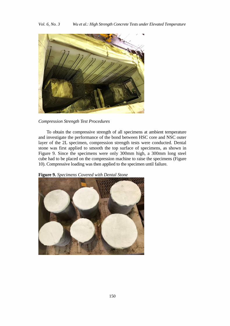
layer of the 2L specimen, compression strength tests were conducted. Dental
stone was first applied to smooth the top surface of specimens, as shown in
Figure 9. Since the specimens were only 300mm high, a 300mm long steel
cube had to be placed on the compression machine to raise the specimens (Figure
10). Compressive loading was then applied to the specimen until failure.
Figure 9. Specimens Covered with Dental Stone

Athens Journal of Technology & Engineering September 2019
151
Figure 10. Steel Cube Base
Fire Test Procedures
Specimen Preparation before Heating
First the top surface of each specimen was insulated with insulating pad
made of asbestos wrapped in insulating cloth. Then the specimen was hung into
the furnace using crane and placed on another insulating pad to make sure the
bottom surface was also insulated. A steel cage was then added and fixed
outside the specimen to protect the furnace from damage caused by the spalled
concrete. The next step was to cover the top and two sides of furnace and
connect thermal couples to the data logger.
Determination of Heating Time
The heating time was mainly determined by the core temperature of the
specimen represented by the temperature recorded from the thermal couple
located at the center. The heating criterion was that, when the core temperature
reached a certain value, the furnace would be shut down immediately. Since
most of the explosive spalling occurs in the temperature range of 200℃ to
400℃ (Kanéma et al. 2011, Fu et al. 2005, Fu and Li 2011, Cheng et al. 2004,
Kanema et al. 2011), 400℃ was chosen as the threshold value to guarantee the
whole specimen would be out of the suspected range of spalling, because the
peripheral temperature must be higher than 400℃ when the core temperature
reaches 400℃. Supposing that spalling does not occur by this time, we can
properly assume that spalling would not occur even if the heating is continued.
However, when conducting the fire test of the second pair of specimens,
Vol. 6, No. 3 Wu et al.: High Strength Concrete Tests under Elevated Temperature
152
namely the 300mm specimens, we found that 400℃ as the threshold value was
unrealistic because it required considerable time and effort to raise the core
temperature to 400℃. However, considering that spalling only occurs somewhat
50mm from the surface of the specimen at most, it is unnecessary to heat the
whole specimen over 400℃. The threshold value for the core temperature of
250mm and 300mm specimens were therefore changed to 300℃. By this time, the
temperature of the outermost 50mm layer would already be far higher than 400℃.
In this way, only parts that were most likely to be subjected to spalling were heated
till beyond the suspected temperature.
During Heating
The specimens cannot be seen through the furnace, so the sounds throughout
the heating process are recorded to indicate whether spalling has already
happened.
After Heating
In consideration of safety and protection of the furnace, the furnace was
not opened until the gas temperature was lower than 400℃ and based on
practical experience, specimens cannot be taken out until they cooled down to
lower than 100℃.
Results and Discussion
General
The ambient compression strength test results of both specimens are presented
in Table 2. Nomenclature is given by “specimen type + specimen outer diameter”.
For instance, 2L200 stands for the 2-layered specimen with outer diameter of
200mm. The column named “Calculated” is the theoretical values of failure
load calculated from the strengths of HSC and NSC. The “Test” column
represents the real failure loads recorded from the ambient compression tests.
The final column is the ratio between the test and calculated values. By
comparing the T/C ratios of 2L and HSC specimens, it is found that the 2L
specimens generally have a lower ratio than HSC, which may indicate a
strength reduction for 2L specimens due to the interface between HSC core and
NSC outer layer. The value of T/C ratio should normally fall in the range of
0.7~1, however, the value of 2L250 specimen is larger than 1, which is
assumed to be caused by the different strength and quality of different batches
of concrete mix. Another thing to note is that no NSC outer layer fell off
throughout the loading process, so it is reasonable to assume that the bond
between HSC core and NSC outer layer is strong enough to withstand the
loading and avoid the separation of two layers. Specimens were too brittle to

Athens Journal of Technology & Engineering September 2019
153
perform residual strength test after several hours’ heating. The gas temperatures
inside the furnace of all three sets of fire tests are compared with the ISO834
standard curve (Figure 9). Results show that the real temperature agrees well
with the target temperature for all fire tests.
Table 2. Ambient Strength Test Results
Specimen Total D
(mm)
NSC layer
t (mm)
Core
d
(mm)
Calculated
(kN) Test (kN)
T/C
Ratio
HSC200 200 0 200 1592.30 1554 0.98
2L200 200 20 160 1390.91 1051 0.76
HSC250 250 0 250 2487.96 1934 0.78
2L250 250 25 200 2173.30 2233 1.03
HSC300 300 0 300 3582.67 3009 0.84
2L300 300 30 240 3129.55 2304 0.74
Figure 11. ISO834 Curve VS Real Gas Temperatures
Fire Test Results Analysis
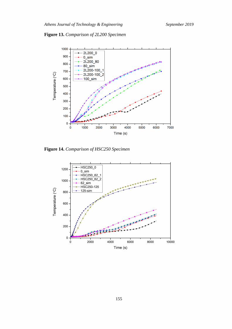
Figure 10 to 15 illustrate the comparison between real temperatures recorded
from thermal couples embedded in the specimens and simulation results by
ABAQUS. Real test curve is named by “Specimen type + outer diameter +
thermal couple position (distance to the center of specimen)”. Except from the

Vol. 6, No. 3 Wu et al.: High Strength Concrete Tests under Elevated Temperature
154
center, every other position should originally have two thermal couples embedded,
however, due to manufacture or heating reasons, some of the thermal couples were
broken and therefore data is missing for some of the positions. The simulation
curves are named by “thermal couple position + sim”. For both HSC and 2L
specimens, a plateau is observed generally at the temperature between 100°C and
150°C, and the nearer to the center, the longer the plateau continues. This
phenomenon is very likely to be caused by the evaporation and diffusion of free
water in the concrete pores (Phan 2008, Lie and Celikkol 1991). When the
temperature reaches around 105°C, free water starts to evaporate and migrate
towards the center of the specimen due to the pore pressure gradient. The transfer
of heat in the concrete is retarded, as a result of energy being absorbed in the
process of evaporation and migration, leading to a decrease in the rate of
temperature rise or a nearly constant temperature period in the early stage of fire
tests. The plateau ends when the concrete temperature rises to about 150°C, by
which time most of the water vapor would have escaped through the concrete
surface and stop migrating. Regarding the HSC and 2L specimens with the same
outer diameter, it is found that the temperatures at corresponding positions have
similar values and trends, which may indicate the interface between the HSC core
and NSC outer layer does not have a significant effect on the heat transfer in
concrete. The NSC outer layer takes effect in preventing the heat from attacking
the HSC core, which improves the performance of HSC under fire to some extent.
Figure 12. Comparison of HSC200 Specimen
Athens Journal of Technology & Engineering September 2019
155
Figure 13. Comparison of 2L200 Specimen
Figure 14. Comparison of HSC250 Specimen

Vol. 6, No. 3 Wu et al.: High Strength Concrete Tests under Elevated Temperature
156
Figure 15. Comparison of 2L250 Specimen
Figure 16. Comparison of HSC300 Specimen

Athens Journal of Technology & Engineering September 2019
157
Figure 17. Comparison of 2L300 Specimen
Spalling Observation
No explosive spalling was observed for all HSC and 2L specimens. The
poor workmanship for casting concrete leading to the low strength and high
permeability of HSC could be the main reason which prevents the happening of
explosive spalling in HSC specimens. Water vapor inside the concrete was
released through the pores under high temperature, pore pressure was not able
to build up to exceed the tensile strength of concrete. As a result, explosive
spalling was avoided for specimens. However, sounds of cracks and pops were
continuously heard during the heating of HSC specimens, which may suggest
the occurrence of minor spalling in the HSC specimens. NSC outer layer of 2L
specimens remained intact after heating, except that the outer layer of 200mm
specimen fell off when hanging out from furnace. The NSC layer of the
200mm 2L specimen is only 20mm thick, which caused certain difficulties to
the casting and manual vibration of the outer layer. Consequently, the bond
between HSC and NSC is relatively weak and it is further weakened under
elevated temperatures. It is deduced that the minimum thickness of NSC outer
layer should be no less than 20mm, reasoning that once the thickness is less
than 20mm it would be difficult to cast and vibrate the outer layer and the bond
between the two layers would become too weak. Visible cracks developed on
the surface of all specimens.
Post Cooling Behavior
Post cooling spalling occurred when the 300mm HSC specimen was taken

Vol. 6, No. 3 Wu et al.: High Strength Concrete Tests under Elevated Temperature
158
out from furnace and cooled down in the ambient temperature. As mentioned
above, thermal chemical spalling consists of sloughing-off spalling at
extremely high temperature and post cooling spalling after exposing to elevated
temperature (Xing et al. 2011, Annerel and Taerwe 2009). The main cause of
thermal-chemical spalling is the break-down of aggregate cement bond, such as
calcium silicate hydroxide and calcium hydroxide (Schneider 1988). The
threshold temperature of thermal-chemical spalling is relatively high at around
750℃. The 300mm specimens were heated for the longest time at around 3.5
hours, and the core temperature would continue to rise for a period of time
even the furnace is shut down. Therefore, the highest core temperature and gas
temperature recorded was 713℃and 1213℃ respectively, which means most
part of the specimen has been heated up to over 700℃. Thus, the occurrence of
post cooling spalling can be considered reasonable.
Conclusions
The bond between the HSC core and NSC outer layer is assumed to be
strong enough to withstand the loading and avoid separation of the two layers
based on the ambient compression test results. However, a strength reduction
may exist for the 2L specimens due to the interface between the HSC core and
NSC outer layer. A plateau is observed at around 100℃ to 150℃, which is
caused by the free water evaporation and diffusion inside the concrete pores.
The effect of the interface between HSC and NSC on heat transfer in concrete
is not significant. And the NSC outer layer is proved to be effective in
preventing the heat from attacking the HSC core. No explosive spalling was
observed for all specimens. Yet sounds of cracks and pops were heard during
the heating process of HSC specimens, which may indicate the occurrence of
minor spalling. Post cooling spalling, whose threshold temperature is at around
750℃, occurred when the 300mm HSC specimen was taken out from furnace
and cooled down in the ambient temperature. The highest core temperature and
gas temperature of the 300mm HSC specimen recorded was 713℃and
1213℃respectively. In practical construction projects, the thickness of NSC
outer layer is recommended to be no less than 20mm, owing to the fact that it
would be difficult to cast and vibrate the outer layer concrete and the bond
between the two layers would become too weak.
Acknowledgments
The authors would like to thank Prof Tan Kang Hai and the NTU Protective
Technology Research Centre for supporting the experimental tests conducted in
the paper. Thanks to Research Grants Council (RGC) of Hong Kong for
supporting the first author’s PhD study in the University of Hong Kong.

Athens Journal of Technology & Engineering September 2019
159
References
Ahmed G., Hurst J (1999) Modeling Pore Pressure, Moisture, and Temperature in
High-Strength Concrete Columns Exposed to Fire. Fire Technology 35(3): 232-
262.
Annerel E, Taerwe L (2009) Revealing the Temperature History in Concrete after Fire
Exposure by Microscopic Analysis. Cement and Concrete Research 39(12):
1239-1249.
Bažant ZP, Chern JC, Thonguthai W (1982) Finite Element Program for Moisture and
Heat Transfer in Heated Concrete. Nuclear Engineering and Design 68(1): 61-70.
Castillo C, Durrani AJ (1990) Effect of Transient High Temperture on High-Strength
Concrete. ACI Materials Journal 87(1): 47-53.
Chaichannawatik B, Sirisonthi A, Hussain Q, Joyklad P (2018) Mechanical Properties
of Fiber Reinforced Concrete. Applied Mechanics and Materials 875: 174-178.
Cheng FP, Kodur V, Wang TC (2004) Stress-Strain Curves for High Strength Concrete
at Elevated Temperatures. Journal of Materials in Civil Engineering, 16(1): 84-
90.
Diederichs U, Jumppanen UM, Penttala V (1988) Material Properties of High
Strength Concrete at Elevated Temperatures 13.
Diederichs U, Jumppanen U, Schneider U (1995) High Temperature Properties and
Spalling Behaviour of High Strength Concrete. 4th International Workshop on
High Performance Concrete—Characteristics, Material Properties and Structural
Performance. Weimar, Germany.
Dwaikat MB, Kodur VKR (2009) Hydrothermal Model for Predicting Fire-Induced
Spalling in Concrete Structural Systems. Fire Safety Journal 44(3): 425-434.
Felicetti R, Gambarova PG., Rosati G., Corsi F, Giannuzzi G. (1996) Residual
Mechanical Properties of High-Strength Concretes Subjected to High-
Temperature Cycles. 4th International Symposium on Utilization of High-
Strength/High-Prformance Concrete.
Fu Y, Wong Y, Poon C, Tang C (2005) Stress-Strain Behaviour of High-Strength
Concrete at Elevated Temperatures. Magazine of Concrete Research 57(9): 535-
544.
Fu Y, Li L (2011) Study on Mechanism of Thermal Spalling in Concrete Exposed to
Elevated Temperatures. Materials and structures, 44(1): 361-376.
Furumura F, Abe T, Shinohara Y (1995) Mechanical Properties of High Strength
Concrete at High Temperatures. Proceedings of the Fourth Weimar Workshop on
High Performance Concrete: Material Properties and Design. Weimar, Germany.
Gawin D, Pesavento F, Schrefler B (2003) Modelling of Hygro-Thermal Behaviour of
Concrete at High Temperature with Thermo-Chemical and Mechanical Material
Degradation. Computer Methods in Applied Mechanics and Engineering, 192(13-
14): 1731-1771.
Hammer TA (1995) High Strength Concrete Phase 3: Compressive Strength and E-
Modulus at Elevated Temperatures. SP6 Fire Resistance, Report 6.1. SINTEF
Structures and Concrete.
Hansen P, Jensen J (1995) High Strength Concrete Phase-3, Fire Resistance and
Spalling Behaviour of LWA Beams. SP-6-Fire Resistance, Report 6.
Hertz K (1984) Heat-Induced Explosion of Dense Concretes. Technical University of
Denmark, Institute of Building Design, No. 166.
Hertz KD (1992) Danish Investigations on Silica Fume Concretes at Elevated
Temperatures. ACI Materials Journal 89(4): 345-347.

Vol. 6, No. 3 Wu et al.: High Strength Concrete Tests under Elevated Temperature
160
Hertz KD (2003) Limits of Spalling of Fire-Exposed Concrete. Fire Safety Journal
38(2): 103-116.
Ichikawa Y, England G.L (2004) Prediction of Moisture Migration and Pore Pressure
Build-Up in Concrete at High Temperatures. Nuclear Engineering and Design,
228(1-3): 245-259.
Jalasutram S, Sahoo DR, Matsagar V (2017) Experimental Investigation of the
Mechanical Properties of Basalt Fiber‐Reinforced Concrete. Structural Concrete
18(2): 292-302.
Jeongwon K, Dongwoo R, Takafumi N (2011) The Spalling Mechanism of High-
Strength Concrete under Fire. Magazine of Concrete Research 63(5): 357-370.
Kalifa P, Menneteau FD, Quenard D (2000) Spalling and Pore Pressure in HPC at
High Temperatures. Cement and Concrete Research 30(12): 1915-1927.
Kanéma M, Pliya P, Noumowé A, Gallias J (2011) Spalling, Thermal, and Hydrous
Behavior of Ordinary and High-Strength Concrete Subjected to Elevated
Temperature. Journal of Materials in Civil Engineering 23(7): 921-930.
Khaliq W, Kodur VKR (2011) Effect of High Temperature on Tensile Strength of
Different Types of High-Strength Concrete. ACI Materials Journal 108(4): 394-
402.
Khaliq W, Kodur V (2013) Behavior of High Strength Fly Ash Concrete Columns
under Fire Conditions. Materials and Structures 46(5): 857-867.
Kodur VKR (2000) Spalling in High Strength Concrete Exposed to Fire: Concerns,
Causes, Critical Parameters and Cures. ASCE Structures Congress. Philadelphia,
Pennsylvania, United States: American Society of Civil Engineers.
Kodur VKR, Cheng FP, Wang TC, Sultan MA (2003) Effect of Strength and Fiber
Reinforcement on Fire Resistance of High-Strength Concrete Columns. Journal
of Structural Engineering 129(2): 253-259.
Kodur VKR, Wang T, Cheng F (2004) Predicting the Fire Resistance Behaviour of
High Strength Concrete Columns. Cement and Concrete Composites 26(2): 141-
153.
Lie TT, Celikkol B (1991) Method to Calculate the Fire Resistance of Circular
Reinforced Concrete Columns. ACI Materials Journal 88(1): 84-91.
Lin W, Lin T, Powerscouche L (1996) Microstructures of Fire-Damaged Concrete.
ACI Materials Journal 93(3): 199-205.
Mindeguia JC, Pimienta P, Noumowé A, Kanema M (2010a) Temperature, Pore
Pressure and Mass Variation of Concrete Subjected to High Temperature—
Experimental and Numerical Discussion on Spalling Risk. Cement and Concrete
Research 40(3): 477-487.
Nassif AY, Burley E, Ridgen S (1995) A New Quantitative Method of Assessing Fire
Damage to Concrete Structures. Magazine of Concrete Research 47(172): 271-
278.
Noumowe AN, Clastres P, Debicki G., Costaz JL (1996) Transient Heating Effect on
High Strength Concrete. Nuclear Engineering and Design 166(1): 99-108.
Ozawa M, Uchida S, Kamada T, Morimoto H (2012) Study of Mechanisms of
Explosive Spalling in High-Strength Concrete at High Temperatures using
Acoustic Emission. Construction and Building Materials 37(Dec): 621-628.
Phan LT, Carino NJ (1998) Review of Mechanical Properties of HSC at Elevated
Temperature. Journal of Materials in Civil Engineering 10(1): 58-65.
Phan LT (2002) High-Strength Concrete at High Temperature - An Overview, 501-518.
Proceedings of 6th International Symposiumon Utilization of High Strength/High
Performance Concrete. Leipzig, Germany.

Athens Journal of Technology & Engineering September 2019
161
Phan LT, Carino NJ (2002) Effects of Test Conditions and Mixture Proportions on
Behavior of High-Strength Concrete Exposed to High Temperatures. ACI
Materials Journal 99(1): 54-66.
Phan L (2008) Pore Pressure and Explosive Spalling in Concrete. Materials and
Structures 41(10): 1623-1632.
Sanjayan G., Stocks LJ (1993) Spalling of High-Strength Silica Fume Concrete in Fire.
ACI Materials Journal 90(2): 170-173.
Schneider U (1988) Concrete at High Temperatures—A General Review. Fire Safety
Journal 13(1): 55-68.
Shirley ST, Burg RG, Fiorato AE (1988) Fire Endurance of High-Strength Concrete
Slabs. Materials Journal 85(2): 102-108.
Sullivan P, Sharshar R (1992) The Performance of Concrete at Elevated Temperatures
(as Measured by the Reduction in Compressive Strength). Fire Technolpgy 28(3):
240-250.
Wang J, Dai Q, Si R, Guo S (2019) Mechanical, Durability, and Microstructural
Properties of Macro Synthetic Polypropylene (PP) Fiber-Reinforced Rubber
Concrete. Journal of Cleaner Production 234(Oct): 1351-1364.
Xing Z, Beaucour AL, Hebert R, Noumowe A, Ledesert B (2011) Influence of the
Nature of Aggregates on the Behaviour of Concrete subjected to Elevated
Temperature. Cement and Concrete Research 41(4): 392-402.
Zdeněk PB, Werapol T (1979) Pore Pressure in Heated Concrete Walls: Theoretical
Prediction. Magazine of Concrete Research 31(107): 67-76.
Zheng Y, Wu X, He G., Shang Q, Xu J, Sun Y (2018) Mechanical Properties of Steel
Fiber-Reinforced Concrete by Vibratory Mixing Technology. Advances in Civil
Engineering 2018. https://doi.org/10.1155/2018/9025715.

Vol. 6, No. 3 Wu et al.: High Strength Concrete Tests under Elevated Temperature
162