Embed Size (px)
Citation preview

ELMECO-5, 4 -6 September 2005, Neleczow, PolandProfessor Jan K. Sykulski, Southampton, UKUniversity of Southampton
High temperature High temperature superconducting transformerssuperconducting transformers
University
of Southampton
Professor Jan SykulskiProfessor Jan SykulskiMSc, PhD, CEng, FIEE, SMIEEE, FInstP, HonProf, FBCS CITP
Head of Electrical Power EngineeringSchool of Electronics & Computer ScienceUniversity of Southampton, UK
ELMECO-5, 4 -6 September 2005, Neleczow, PolandProfessor Jan K. Sykulski, Southampton, UKUniversity of Southampton
Superconducting power devicesSuperconducting power devices
Why ?

ELMECO-5, 4 -6 September 2005, Neleczow, PolandProfessor Jan K. Sykulski, Southampton, UKUniversity of Southampton
Losses in conventional and superconducting designs
Superconducting power devicesSuperconducting power devices

ELMECO-5, 4 -6 September 2005, Neleczow, PolandProfessor Jan K. Sykulski, Southampton, UKUniversity of Southampton
andand
•• smaller size smaller size
•• reduced weightreduced weight
Superconducting power devicesSuperconducting power devices
Railway transformersRailway transformers
superconducting
conventional

ELMECO-5, 4 -6 September 2005, Neleczow, PolandProfessor Jan K. Sykulski, Southampton, UKUniversity of Southampton
LTS (Low Temperature Superconductivity) has not been successful in electric power applications
• low reliability• high cost• difficult technology
Impact of HTS (High Temperature Superconductivity)
• better thermal stability• cheaper cooling• improved reliability
Superconducting power devicesSuperconducting power devices

ELMECO-5, 4 -6 September 2005, Neleczow, PolandProfessor Jan K. Sykulski, Southampton, UKUniversity of Southampton
Applications of HTSApplications of HTS(High Temperature Superconductivity)(High Temperature Superconductivity)
• conductivity 106 better than copper
• current density 10 times larger than in copper windings• cheap technology (often compared to water cooling)
• great potential in electric power applications (generators, motors, fault current limiters, transformers, flywheels, cables, etc.), as losses and/or size are significantly reduced
• operate at liquid nitrogen temperature (78K)
• ceramic materials discovered in 1986
• present a modelling challenge because of very highly non-linear characteristics and anisotropic properties of materials, and due to unconventional designs

ELMECO-5, 4 -6 September 2005, Neleczow, PolandProfessor Jan K. Sykulski, Southampton, UKUniversity of Southampton
Common HTS materials:Common HTS materials:
Yttrium compounds (YBCO)Yttrium compounds (YBCO)YY11BaBa22CuCu33OO77--x x (123)(123) TTcc = 92 K= 92 KYY22BaBa44CuCu77OO1515--yy (247)(247) TTcc = 95 K= 95 K
Bismuth compounds (BISCCO)Bismuth compounds (BISCCO)BiBi22SrSr22CaCa11CuCu22OOyy (2212)(2212) TTcc = 80 K= 80 KBiBi22--xxPbPbxxSrSr22CaCa22CuCu33OOyy (2223)(2223) TTcc = 110 K= 110 K
Thallium compoundsThallium compounds(TlPb)(TlPb)11SrSr22CaCa22CuCu33OO99 (1223)(1223) TTcc = 120 K= 120 KTlTl22BaBa22CaCa22CuCu33OO1010 (2223)(2223) TTcc = 125 K= 125 K
Mercury compoundsMercury compoundsHgHg11BaBa22CaCa22CuCu33OO1010 (1223)(1223) TTcc = 153 K= 153 K
MultiMulti--filament HTS tapes filament HTS tapes
HTS coilsHTS coils

ELMECO-5, 4 -6 September 2005, Neleczow, PolandProfessor Jan K. Sykulski, Southampton, UKUniversity of Southampton
Applications of High Temperature Applications of High Temperature Superconductivity (HTS)Superconductivity (HTS)
HTS fault current limiter based on melt-cast BSSCO
40kW 3000 rpm reluctance motor with YBCO bulk parts in the rotor
Concept and realization of a three-phase HTS power cable
400 kW HTS synchronous motor
BSCCO HTS magnet for whole body open MRI
ELMECO-5, 4 -6 September 2005, Neleczow, PolandProfessor Jan K. Sykulski, Southampton, UKUniversity of Southampton
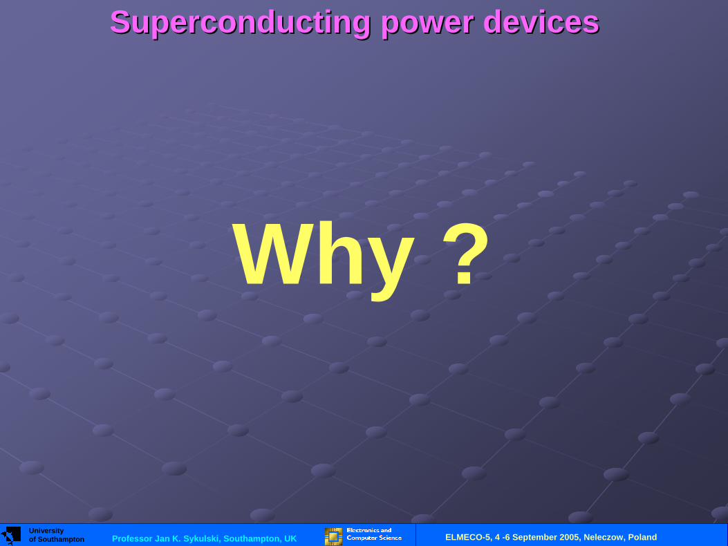
All conceptual HTS designs and small demonstartors useBSCCO tapes at temperatures between 20K and 30K
• at 30K critical fields and currents order of magnitude better than at 78K
• it is possible to have a core-less design
But !!!
• liquid neon or helium gas needed
• increased cost and complexity of refrigeration plant
• reduced thermodynamic efficiency
• worse reliability and higher maintenance requirements
Superconducting power devicesSuperconducting power devices

ELMECO-5, 4 -6 September 2005, Neleczow, PolandProfessor Jan K. Sykulski, Southampton, UKUniversity of Southampton
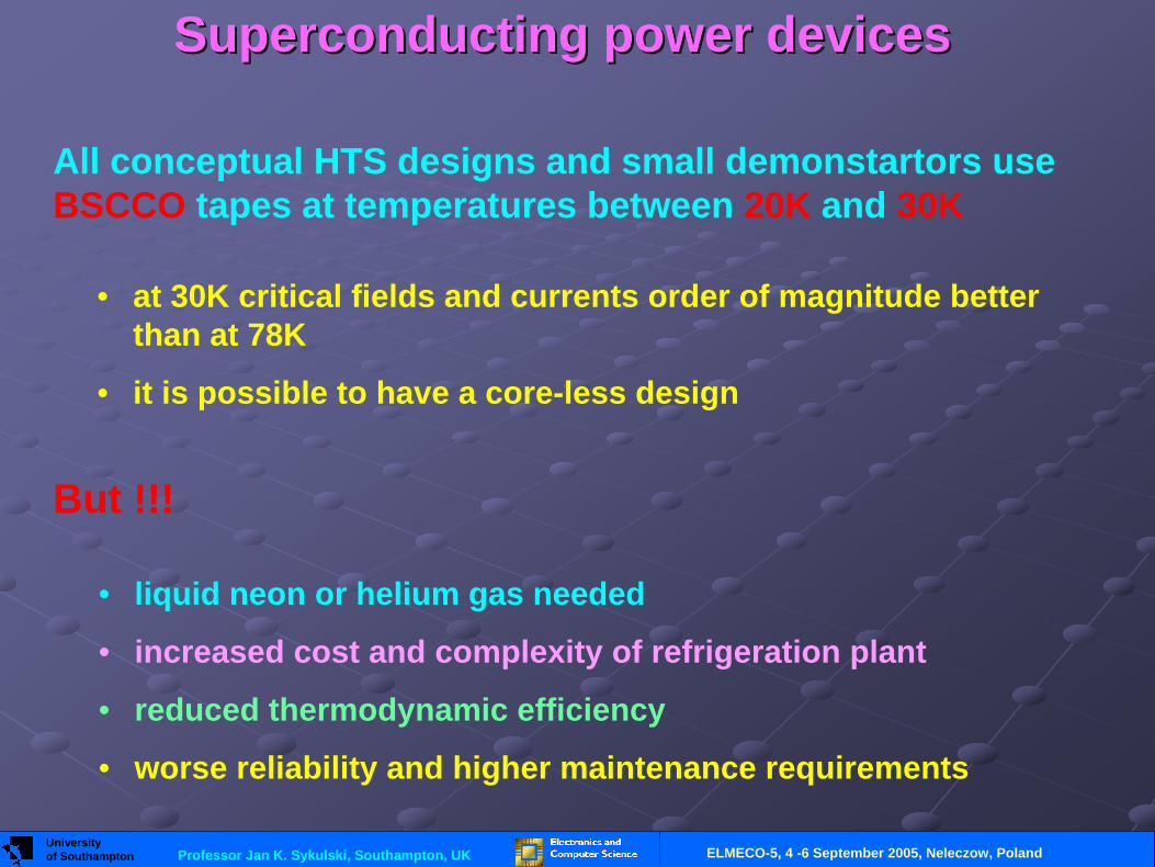
Superconducting generators and motorsSuperconducting generators and motors
Synchronous generator at Southampton• 100 kVA, 2 pole
• cooling at 78 / 81 / 65 / 57 K(liquid nitrogen or air / sub-cooled nitrogen or air)
• magnetic core rotor design
- reduces the ampere-turns required by a factor of ten
- significantly reduces fields in the coils
• rotor made of cryogenic steel (9%)
• 10 identical pancake coils made of BSCCO (Ag clad Bi-2223), length of wire approx 10 x 40m

ELMECO-5, 4 -6 September 2005, Neleczow, PolandProfessor Jan K. Sykulski, Southampton, UKUniversity of Southampton
Southampton 100kVA HTS generatorSouthampton 100kVA HTS generator
Slip Rings(DC current)
Coupling toDriving Motor
& Optical Link
A View A
Stator
Stator CopperWinding
Vacuum Vessel& Superinsulation
Support Platform
BView B
Detail
9% Ni SteelFlux Diverter
HTS Coil
Copper Thermal Shield
9% Ni Steel RotorEight Fixing Postions
of Torque Spider
Six places to link Torque Spiderto the Rotor Body (See Text)
Torque Spider
Stiffening Cone
Cooling Duct
Stainless Steel Former
Damping Screen
Vapour Seal
RotatingLiquid Seal
Clutch-LikeLiquid Coupling
Liquid CouplingJunction
Superinsulation
Seal

ELMECO-5, 4 -6 September 2005, Neleczow, PolandProfessor Jan K. Sykulski, Southampton, UKUniversity of Southampton
Eddy currents occur as 48th time harmonicEddy currents occur as 48th time harmonicTransient losses were estimated and subtracted Transient losses were estimated and subtracted Total noTotal no--load loss found to be load loss found to be 0.264 W0.264 W
NoNo--load lossesload losses
Modelling of EddyModelling of Eddy--Current LossCurrent Loss

ELMECO-5, 4 -6 September 2005, Neleczow, PolandProfessor Jan K. Sykulski, Southampton, UKUniversity of Southampton
ModellingModelling of fullof full--load lossesload losses
Eddy currents due to MMF harmonics

ELMECO-5, 4 -6 September 2005, Neleczow, PolandProfessor Jan K. Sykulski, Southampton, UKUniversity of Southampton
Summary of eddy current lossesSummary of eddy current losses
• No-load losses: 0.264 W
• Full-load losses: 2.319 W
• These losses are released at liquid nitrogen temperature and have to be removed using the inefficient refrigeration system
• Each 1W of loss to be removed requires between15 – 25 W of installed refrigeration power at 78K(a similar figure at 4K would be about 1000 W)
ELMECO-5, 4 -6 September 2005, Neleczow, PolandProfessor Jan K. Sykulski, Southampton, UKUniversity of Southampton

ELMECO-5, 4 -6 September 2005, Neleczow, PolandProfessor Jan K. Sykulski, Southampton, UKUniversity of Southampton
Superconducting generator testingSuperconducting generator testing

ELMECO-5, 4 -6 September 2005, Neleczow, PolandProfessor Jan K. Sykulski, Southampton, UKUniversity of Southampton
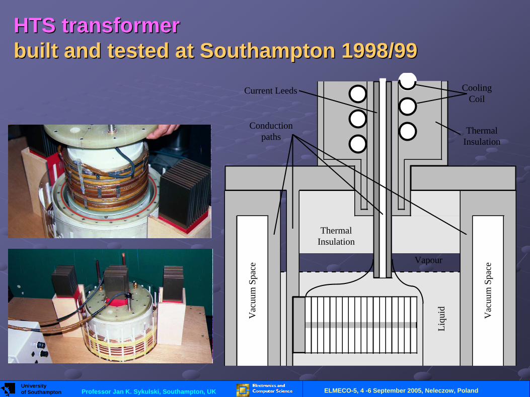
HTS transformerHTS transformerbuilt and tested at Southampton 1998/99built and tested at Southampton 1998/99

ELMECO-5, 4 -6 September 2005, Neleczow, PolandProfessor Jan K. Sykulski, Southampton, UKUniversity of Southampton
HTS transformerHTS transformerbuilt and tested at Southampton 1998/99built and tested at Southampton 1998/99
ELMECO-5, 4 -6 September 2005, Neleczow, PolandProfessor Jan K. Sykulski, Southampton, UKUniversity of Southampton
HTS transformerHTS transformerbuilt and tested at Southampton 1998/99built and tested at Southampton 1998/99
Vac
uum
Spa
ce
Conductionpaths
ThermalInsulation
CoolingCoil
ThermalInsulation
Current Leeds
Vac
uum
Spa
ce
Vapour
Liqu
id

ELMECO-5, 4 -6 September 2005, Neleczow, PolandProfessor Jan K. Sykulski, Southampton, UKUniversity of Southampton
HTS transformerHTS transformerbuilt and tested at Southampton 1998/99built and tested at Southampton 1998/99
Field plots with and without flux diverters

ELMECO-5, 4 -6 September 2005, Neleczow, PolandProfessor Jan K. Sykulski, Southampton, UKUniversity of Southampton
0
1
2
3
4
5
6
7
8
9
10
11
0 10 20 30 40 50 60Secondary Current (A)
Loss
(W)
Measured (no Flux Diverters)
Calculated (no Flux Diverters)
Calculated (with Flux Diverters)
Measured (with Flux Diverters)
HTS transformerHTS transformerbuilt and tested at Southampton 1998/99built and tested at Southampton 1998/99

ELMECO-5, 4 -6 September 2005, Neleczow, PolandProfessor Jan K. Sykulski, Southampton, UKUniversity of Southampton
Design feasibility study for a 240MVA HTS grid autoDesign feasibility study for a 240MVA HTS grid auto--transformer transformer
Principal parameters:kVA: 240,000Normal Volts: 400/132 kVTappings: 132 kV + 15% - 5% in 14 stepsLine current: 346/1054 ADiagram No: Yy0 AutoReactance: 20%Rated current densities:
series winding* = 39.1 A/mm2
common winding* = 36.9 A/mm2
tap winding = 3.0 A/mm2 (conventional)(* average over composite conductor section, comprising both superconducting and matrix materials).

ELMECO-5, 4 -6 September 2005, Neleczow, PolandProfessor Jan K. Sykulski, Southampton, UKUniversity of Southampton
Design feasibility study for a 240MVA HTS grid autoDesign feasibility study for a 240MVA HTS grid auto--transformer transformer
HTSHTS ConventionalConventional
Core loss 8 9
Clamp stray loss 5 5
Tank loss - 7
Total copper loss <1 (tap) 79
Refrigeration power 7 -
Gas-cooling fan loss 2 -
Estimated total lossEstimated total loss 2323 100 *100 *
Loss analysisLoss analysis
* Total loss of conventional design = 100%* Total loss of conventional design = 100%

ELMECO-5, 4 -6 September 2005, Neleczow, PolandProfessor Jan K. Sykulski, Southampton, UKUniversity of Southampton
Design feasibility study for a 240MVA HTS grid autoDesign feasibility study for a 240MVA HTS grid auto--transformer transformer
Comparison of technical features Comparison of technical features …… 11ParameterParameter HTSHTS ConventionalConventional
Core length *height *thickness *
Window, height * × width *
88.582.4100
70 × 78.5
100100100
100 × 100Core weight *Winding weight *Tap winding weight *
806.3100
100100100
Cooling of core and tap winding
Cooling of common and series winding
Forced N2 gas
Liquid N2(with refrigeration)
ONAN/OFAF
ONAN/OFAF
* shown as percentage of the appropriate value for a conventiona* shown as percentage of the appropriate value for a conventional transformerl transformer

ELMECO-5, 4 -6 September 2005, Neleczow, PolandProfessor Jan K. Sykulski, Southampton, UKUniversity of Southampton
Design feasibility study for a 240MVA HTS grid autoDesign feasibility study for a 240MVA HTS grid auto--transformer transformer
Comparison of technical features Comparison of technical features …… 22ParameterParameter HTSHTS ConventionalConventional
Guaranteed % reactanceB in core, TJ rated, rms, A/mm2
201.6738
201.672.83
Rated loss, total * 23 100
Overload capabilityThrough fault capability,pu (+ doublingh transient),recoveruy time without
disconnectionSurvival time at 5 pu(+ doubling transient)
2 pu, many hours
2 pu, 64 ms
166 ms
1.3 pu, 6 hrs1.5 pu, 30 min
5 pu, 3 s
seconds (> 3)
* shown as percentage of the appropriate value for a conventiona* shown as percentage of the appropriate value for a conventional transformerl transformer

ELMECO-5, 4 -6 September 2005, Neleczow, PolandProfessor Jan K. Sykulski, Southampton, UKUniversity of Southampton
Design feasibility study for a 240MVA HTS grid autoDesign feasibility study for a 240MVA HTS grid auto--transformer transformer
Cost savings on continuous full loadCost savings on continuous full load
Savings/expenditure %
Saving on core plate 1
Saving on continuously transposed copper 7
Saving on copper losses, discount over 10 years 65
Cost of refrigeration plant −21
First-cost equivalent expenditure on refrigeration drive power, discount over 10 years −6
Cost of AC conductor, total of 7371 amp-kilometres −10
Total equivalent first-cost saving 36

ELMECO-5, 4 -6 September 2005, Neleczow, PolandProfessor Jan K. Sykulski, Southampton, UKUniversity of Southampton
Design feasibility study for a 240MVA HTS grid autoDesign feasibility study for a 240MVA HTS grid auto--transformer transformer
But !!!But !!!
•• The load factor for a grid transformer is very low, The load factor for a grid transformer is very low,
e.g. in the UK it is 0.23 average or 0.26 rms.e.g. in the UK it is 0.23 average or 0.26 rms.
•• Thus the savings may not actually happen !Thus the savings may not actually happen !
However However ……

ELMECO-5, 4 -6 September 2005, Neleczow, PolandProfessor Jan K. Sykulski, Southampton, UKUniversity of Southampton
Parallel operation Parallel operation
400 kV
132 kV
Main
Reserve
SGT1 SGT2

ELMECO-5, 4 -6 September 2005, Neleczow, PolandProfessor Jan K. Sykulski, Southampton, UKUniversity of Southampton
Parallel operation Parallel operation
Probability density of load for a typical grid transformer

ELMECO-5, 4 -6 September 2005, Neleczow, PolandProfessor Jan K. Sykulski, Southampton, UKUniversity of Southampton
Parallel operation Parallel operation
400 kV
132 kV
Main
Reserve
HTS Conventional

ELMECO-5, 4 -6 September 2005, Neleczow, PolandProfessor Jan K. Sykulski, Southampton, UKUniversity of Southampton
Parallel operation Parallel operation
Load probability density and loss as a function of load for a HTS transformer in parallel with a (normally)
unconnected conventional unit. The mean load is around 0.7 p.u.

ELMECO-5, 4 -6 September 2005, Neleczow, PolandProfessor Jan K. Sykulski, Southampton, UKUniversity of Southampton
Parallel operation Parallel operation
Cost analysisCost analysis
Costs (Costs (££k)k) SuperconductingSuperconducting+ conventional+ conventional 2 2 ×× conventionalconventional
Transformer Transformer capitalcapital 1,000 + 1,2301,000 + 1,230 2,0002,000
LossesLosses 0.105 0.105 ×× 600 600 ×× 33 0.426 0.426 ×× 600 600 ×× 33
Total 2,419 2,768

ELMECO-5, 4 -6 September 2005, Neleczow, PolandProfessor Jan K. Sykulski, Southampton, UKUniversity of Southampton
Conclusions Conclusions …… 11• Increasing activity around the world in HTS
applications for power devices
• All existing demonstrators use HTS tapes at temperatures 20 to 30 K (helium or neon gas)
• Southampton designs for 78K
• Parameters of new tapes improved dramatically
• Ability to predict and reduce all ‘cold’ losses of paramount importance to show economic advantages of HTS designs

ELMECO-5, 4 -6 September 2005, Neleczow, PolandProfessor Jan K. Sykulski, Southampton, UKUniversity of Southampton
Conclusions Conclusions …… 22
• HTS power devices are
technically viable
• HTS power devices may also be
economically competitive

ELMECO-5, 4 -6 September 2005, Neleczow, PolandProfessor Jan K. Sykulski, Southampton, UKUniversity of Southampton