Embed Size (px)
Citation preview
Nonlinear Dyn (2017) 87:2677–2695DOI 10.1007/s11071-016-3220-4
ORIGINAL PAPER
Highly efficient continuous bistable nonlinear energy sinkcomposed of a cantilever beam with partial constrainedlayer damping
Xin Fang · Jihong Wen · Jianfei Yin ·Dianlong Yu
Received: 4 November 2015 / Accepted: 15 November 2016 / Published online: 2 December 2016© Springer Science+Business Media Dordrecht 2016
Abstract This paper focuses on the transient non-linear dynamics and targeted energy transfer (TET)of a Bernoulli–Euler beam coupled to a continuousbistable nonlinear energy sink (NES). This NES com-prises a cantilever beam with the partial constrainedlayer damping (PCLD) and an end mass controlled bya nonlinear magnetostatic interaction force. The theo-retical model of the nonlinear system is built based onthe Lagrange equations and assumed-modes expansionmethod. A new parameter system damping ratio is pro-posed to evaluate the TET efficiencies. Impact experi-ments are carried out to verify the theoretical modeland mechanisms. The results show that the bistableNES can achieve high and strongly robust TET effi-ciencies under broad-range impacts. The shear modu-lus of the viscoelastic layer, the length of the PCLDand the end mass have significant influences on TETefficiencies. Analyses of the TET mechanisms in thebistable NES show the following: steady transition ofthe stable state is an important reason for maintaininghigh TET efficiencies; nonlinear beatings can occur
Electronic supplementary material The online version ofthis article (doi:10.1007/s11071-016-3220-4) containssupplementary material, which is available to authorized users.
X. Fang · J. Wen (B) · J. Yin · D. YuLaboratory of Science and Technology on IntegratedLogistics Support, National University of DefenseTechnology, Changsha 410073, Hunan, Chinae-mail: [email protected]
J. Yine-mail: [email protected]
in high-frequency, fundamental and long-period sub-harmonic branches; and resonance captures featuringfundamental and subharmonic also help achieve rapidenergy dissipation.
Keywords Nonlinear dynamics · Bistable nonlinearenergy sink · Transient impact · Continuous structure ·Constrained layer damping · Vibration
1 Introduction
Vibration has large influences on the function, noisecontrol and reliability of a mechanical system. Pas-sive vibration control techniques have been chosenas a primary method in many facilities because ofthe advantages of high efficiency and lack of powerconsumption. The efficiencies of the traditional linearvibration absorbers or tuned mass dampers (TMDs)are restricted by their narrowband and poor robust-ness [1,2]. A nonlinear approach for vibration suppres-sion was considered to enable maintain high perfor-mance with a broader bandwidth under transient exci-tations. The passive nonlinear targeted energy transfer(TET) technique utilizes nonlinear mode localizationand internal resonance to irreversibly transfer transientvibration energy from the primary system to a nonlinearenergy sink (NES) that eventually dissipates the energyin the NES [3]. The robustness of an NES arises fromthe absence of the preferential linear natural frequency[4]. Research has been extensively investigated the phe-
123
2678 X. Fang et al.
nomena and mechanisms of NES [5–7]. FundamentalTET, subharmonic TET and TET initiated by nonlin-ear beating are the main mechanisms, and nonlinearbeating along the high-frequency special branches rep-resents the most efficient mechanism of energy dissi-pation [8]. Presently, several types of NESs have beenproposed and studied, such as oscillating dissipativeattachments with essentially strong nonlinear stiffness[9–12], rotational elements [13,14], vibro-impact NES[15,16] andmagnet-basedNES [17]. Experiments havebeen carried out to verify the performance of NESs[18]. However, a traditional NES has a critical energythreshold in the transient regime in order to initiatethe nonlinear beating [2,8,18], resulting in only havinghigh TET efficiency under moderate transient impacts.Recently, a bistable NES [19,20] was proposed tobreakthrough the limit of the input energy threshold tomaintain high performance of shock mitigation undera broad range of input energy. To explore the transientdynamics in a linear system coupled to a lightweightbistablemass, Romeo et al. [21] carried out a numericalstudy and Manevitch et al. [22] presented an analyti-cal study with the complexification-averaging method[23]. Both studies focused on the impulsively excitedlinear oscillator (LO) to the bistable NES. The resultsshow that, along with the main regime of 1:1 reso-nance capture, the superharmonic 1:3 resonance cap-ture regime can also be realized and thus results in astrong energy exchange between the LO and bistableNES. However, the TETmechanisms and the nonlineardynamics of the bistable NES need more research andexperimental validations.
At present, a NES consists of a discrete single-degree-of-freedom (SDOF) nonlinear oscillator and aviscous damper. The transient dynamic behaviors of theSDOF NES coupled to a LO have been widely inves-tigated. The only performance index of absorbers con-sidered is the percentage of instantaneous total energydissipated by the NES. However, this index percentagecannot reflect the decay rate of vibration energy thatis an important parameter in practice. Recently, Faridand Gendelman [24] used the relative amount of theenergy left in the system after a given time as an alter-native index.Moreover, research on theNES composedof continuous structures is minimal. The bistable con-tinuous structures were employed as vibration energyharvesters (VEHs) to achieve good performance underlow-frequency excitations [25]. These VEHs usuallyconsist of a cantilever beam attached with piezoelec-
tric generators. Most of the relevant literature modeledthe bistable VEH as a SDOF oscillator by consider-ing the first-order modal of the beam and consideredthe primary structures as rigid bodies [25–29]. How-ever, these modeling methods are not proper for broad-range and high-frequency vibrations and cannot revealthe deformation of primary structures.
From the review above, it is important and interest-ing to study the nonlinear dynamics of a continuouselastic structure coupled to a continuous bistable NES.This paper focuses on the transient nonlinear dynamicsand the TET efficiency of a continuous bistable energysink coupled to an elastic beam. The NES consistsof a cantilever beam attached with partial constrainedlayer damping (PCLD) and a magnetostatic field thatproduces an interaction force as the nonlinear restor-ing force. Based on the Lagrange equations and theassumed-modes expansion method, the motion differ-ential equations are established to study the dynamicbehaviors with numerical solutions. Besides the com-monly used parameter percentage of total energy dissi-pated by NES, another parameter system damping ratiois defined to evaluate the TET efficiency. Impact exper-iments on the structure with different restoring forcesare carried out to validate the theoretical model and thebistable transition behaviors. Then, the influences ofdifferent PCLD and structure parameters on TET effi-ciencies are investigated. Finally, this paper analyzesand summarizes the TET mechanisms of the bistableNES. There are five sections in this paper. The secondsection presents the process to establish the theoreticalmodel and the analysis method. Impact experimentsand comparisons between the experimental and theo-retical results are described in Sect. 3. The efficienciesand mechanisms of the bistable NES are analyzed inSect. 4 based on the numerical methods. Finally, wemake conclusions in Sect. 5.
2 Modeling and derivation
2.1 Model description
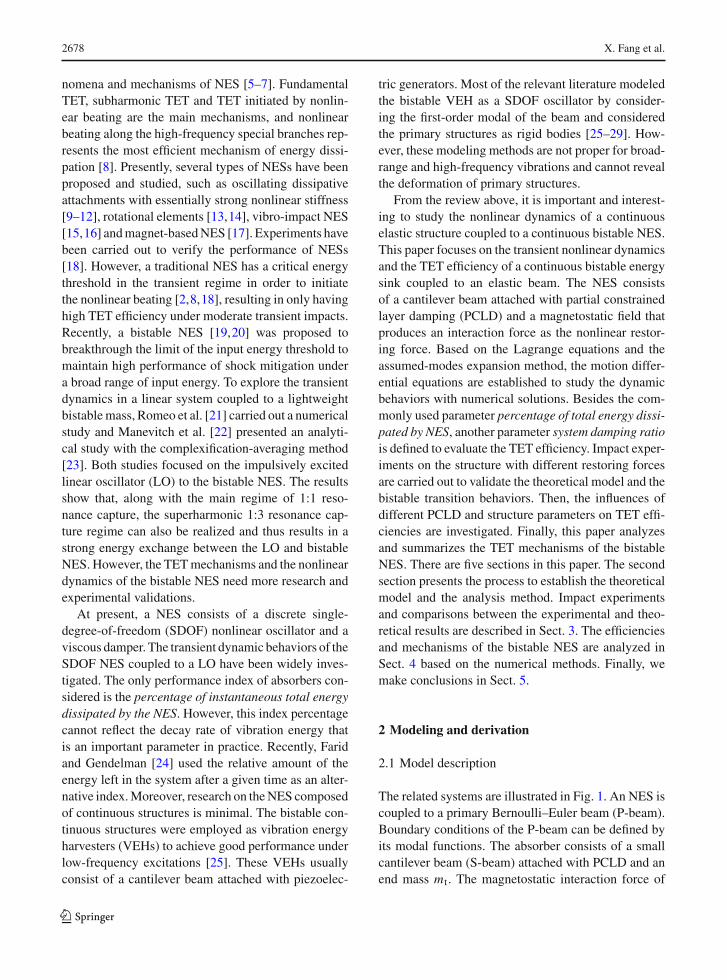
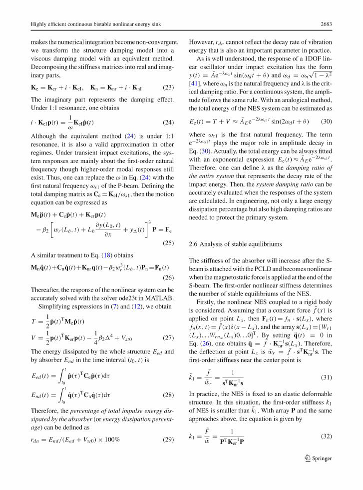
The related systems are illustrated in Fig. 1. An NES iscoupled to a primary Bernoulli–Euler beam (P-beam).Boundary conditions of the P-beam can be defined byits modal functions. The absorber consists of a smallcantilever beam (S-beam) attached with PCLD and anend mass mt . The magnetostatic interaction force of
123
Highly efficient continuous bistable nonlinear energy sink 2679
Repulsive Force NES
Attractive Force NES
L
0LO 1O 2ObL
cL
mL
2pm
1pm tmcL
nL
P-beam
S-beam
Fig. 1 The model of a monostable/bistable energy sink coupledto an elastic beam
the permanent magnets provides the nonlinear restor-ing force for the S-beam. There are two types of con-figurations: repulsive force and attractive force. Theirmodeling methods are identical; thus, only the attrac-tive force NES is taken into account in the experimentsand analyses. TheS-beam isfixed to theP-beamat pointO1 with a rigid strut whose height is Lc. The other strutis fixed at point O2 to support the magnets. For attrac-tive force NES, the two smaller magnets on point O2
are symmetrical to the undeformed S-beam. By mod-ulating the magnetic forces, the absorber can behaveas a monostable NES or a bistable NES. It is a linearabsorber if the interaction force is zero. The masses ofthe struts are mp1 and mp2, respectively. Other para-meters are labeled in Fig. 1.
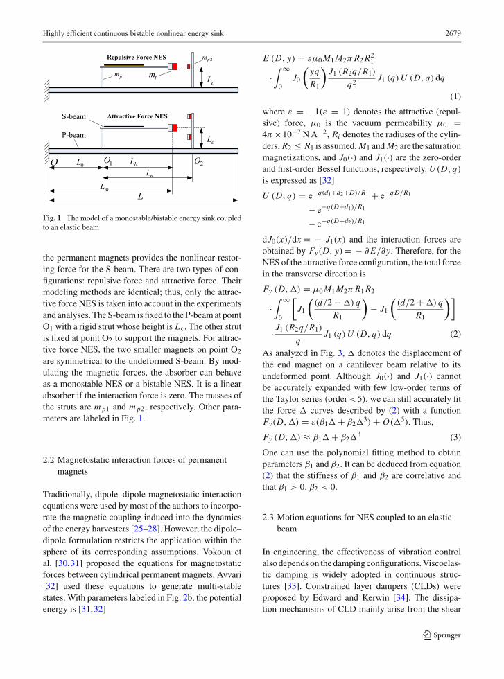
2.2 Magnetostatic interaction forces of permanentmagnets
Traditionally, dipole–dipole magnetostatic interactionequations were used by most of the authors to incorpo-rate the magnetic coupling induced into the dynamicsof the energy harvesters [25–28]. However, the dipole–dipole formulation restricts the application within thesphere of its corresponding assumptions. Vokoun etal. [30,31] proposed the equations for magnetostaticforces between cylindrical permanent magnets. Avvari[32] used these equations to generate multi-stablestates. With parameters labeled in Fig. 2b, the potentialenergy is [31,32]
E (D, y) = εμ0M1M2πR2R21
·∫ ∞
0J0
(yq
R1
)J1 (R2q/R1)
q2J1 (q)U (D, q) dq
(1)
where ε = −1(ε = 1) denotes the attractive (repul-sive) force, μ0 is the vacuum permeability μ0 =4π ×10−7 NA−2, Ri denotes the radiuses of the cylin-ders, R2 ≤ R1 is assumed,M1 andM2 are the saturationmagnetizations, and J0(·) and J1(·) are the zero-orderand first-order Bessel functions, respectively.U (D, q)
is expressed as [32]
U (D, q) = e−q(d1+d2+D)/R1 + e−qD/R1
− e−q(D+d1)/R1
− e−q(D+d2)/R1
dJ0(x)/dx = − J1(x) and the interaction forces areobtained by Fy(D, y)= − ∂E/∂y. Therefore, for theNES of the attractive force configuration, the total forcein the transverse direction is
Fy (D,�) = μ0M1M2πR1R2
·∫ ∞
0
[J1
((d/2 − �) q
R1
)− J1
((d/2 + �) q
R1
)]
· J1 (R2q/R1)
qJ1 (q)U (D, q) dq (2)
As analyzed in Fig. 3, � denotes the displacement ofthe end magnet on a cantilever beam relative to itsundeformed point. Although J0(·) and J1(·) cannotbe accurately expanded with few low-order terms ofthe Taylor series (order< 5), we can still accurately fitthe force � curves described by (2) with a functionFy(D,�) = ε(β1� + β2�
3) + O(�5). Thus,
Fy (D,�) ≈ β1� + β2�3 (3)
One can use the polynomial fitting method to obtainparameters β1 and β2. It can be deduced from equation(2) that the stiffness of β1 and β2 are correlative andthat β1 > 0, β2 < 0.
2.3 Motion equations for NES coupled to an elasticbeam
In engineering, the effectiveness of vibration controlalso depends on the damping configurations.Viscoelas-tic damping is widely adopted in continuous struc-tures [33]. Constrained layer dampers (CLDs) wereproposed by Edward and Kerwin [34]. The dissipa-tion mechanisms of CLD mainly arise from the shear
123
2680 X. Fang et al.
yD D
y
1d 2d
12R
22R
y
x
(a) (b)
y
xz
o
Fig. 2 Magnetostatic interaction in a dipole–dipole configura-tion and b cylinder–cylinder configuration
Δ
ϕ
d
1yF
2yF
yx
1x2x
Fig. 3 Interaction forces generated by repulsive and attractiveforces
deformation of the viscoelastic layer [33]. PCLD wasproposed by Plunkett and Lee [35] to increase struc-tural damping.Many researchers used the genetic algo-rithm method [36], moving asymptotes [37] and evo-lutionary structural optimization [38] to optimize theparameters of CLDs and PCLDs. This paper adoptedunilateral PCLD to realize the damping of NES. Theanalytical calculations of CLD and PCLD are basedon modal strain energy approaches proposed by Meadet al. [39,40].
The basic assumptions for the analytical model are(1) the presence of shear strain in the base and con-strained layers; the rotary inertia of all layers is neg-ligible; (2) the presence of only shear stress but nonormal stress in the viscoelastic layer; (3) the strainis small compared to the structure for both linear andnonlinear NES; (4) the slipping does not occurs at theinterfaces between layers and the deformations at theinterfaces are continuous; (5) the plane transverse to themiddle layer cross section remains planar during bend-ing; and (6) the transverse displacements of all layersare identical. Based on these assumptions, the deforma-tion patterns of the base beam, viscoelastic layer andconstrained layer are illustrated in Fig. 4.
The geometry functions of displacements are
uc = uv + hv (γ − θ)/2 − hcθ/2
bu
vu
cu
γ
θ
bh
vh
chy
xrw
Fig. 4 Deformation pattern of three layers in PCLD treatment
ub = uv − hv (γ − θ)/2 + hbθ/2 (4)
where subscripts ‘b’, ‘v’ and ‘c’ denote the base beamof the absorber, the viscoelastic layer and the con-strained layer, respectively; ub, uv and uc are longitu-dinal displacements (in x direction) of middle planes;wr is the transverse displacement of the base beam rel-ative to point O1 in Fig. 1, and angle θ = ∂wr/∂x ; γ
denotes the angle of the transverse plane of viscoelas-tic layer relative to its transverse direction; and hb, hv,and hc represent the heights of the corresponding lay-ers. Solving Eq. (4) obtains
uv = ub + uc2
+ hc − hb4
∂wr
∂x
γ = 1
hv
[uc − ub + ht
∂wr
∂x
], ht = hc+hb+2hv
2(5)
Assuming that the longitudinal displacement of the P-beam is negligible, the P-beam has a transverse dis-placement y(x, t) only. Because the strut connectingthe P-beam and the S-beam is rigid, the displacementsand angles for the two beams should be identical atpoint O1. Assuming the displacement at point O1 isϕ(t) = y(L0, t), the absolute displacement of the S-beam is
w (x, t)=wr +ϕ+x sin θ0 ≈ wr +ϕ+x∂y (L0, t)
∂x(6)
where x is the distance between the point on the S-beamand its root O1. For the P-beam, a further assumption ismade that additionalmassmpi are scattered at positionsLxi .
When the absorber is coupled to the P-beam, thekinetic energy of the entire system is
T = Tp + Tb + Tv + Tc + Tm (7)
123
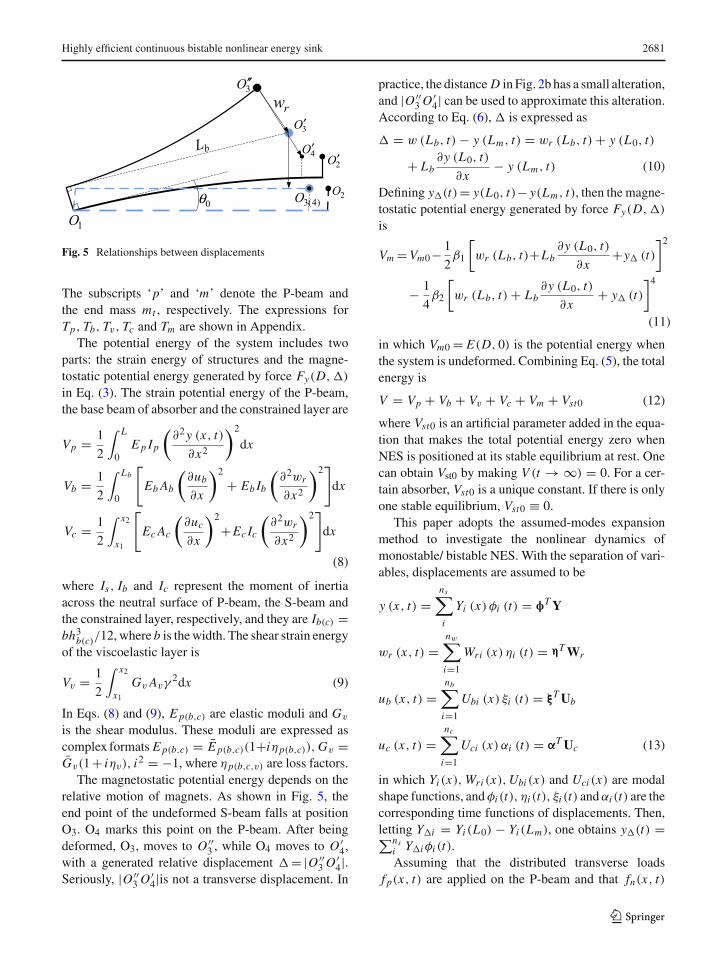
Highly efficient continuous bistable nonlinear energy sink 2681
rw
1O
2O
3O′
2O′
0θ
bL
3(4)O
3O′′
4O′
Fig. 5 Relationships between displacements
The subscripts ‘p’ and ‘m’ denote the P-beam andthe end mass mt , respectively. The expressions forTp, Tb, Tv, Tc and Tm are shown in Appendix.
The potential energy of the system includes twoparts: the strain energy of structures and the magne-tostatic potential energy generated by force Fy(D,�)
in Eq. (3). The strain potential energy of the P-beam,the base beam of absorber and the constrained layer are
Vp = 1
2
∫ L
0Ep Ip
(∂2y (x, t)
∂x2
)2
dx
Vb = 1
2
∫ Lb
0
[EbAb
(∂ub∂x
)2
+ Eb Ib
(∂2wr
∂x2
)2]dx
Vc = 1
2
∫ x2
x1
[Ec Ac
(∂uc∂x
)2
+Ec Ic
(∂2wr
∂x2
)2]dx
(8)
where Is, Ib and Ic represent the moment of inertiaacross the neutral surface of P-beam, the S-beam andthe constrained layer, respectively, and they are Ib(c) =bh3b(c)/12, where b is thewidth. The shear strain energyof the viscoelastic layer is
Vv = 1
2
∫ x2
x1GvAvγ
2dx (9)
In Eqs. (8) and (9), Ep(b,c) are elastic moduli and Gv
is the shear modulus. These moduli are expressed ascomplex formats Ep(b,c) = E p(b,c)(1+iηp(b,c)),Gv =Gv(1+ iηv), i2 = −1, where ηp(b,c,v) are loss factors.
The magnetostatic potential energy depends on therelative motion of magnets. As shown in Fig. 5, theend point of the undeformed S-beam falls at positionO3. O4 marks this point on the P-beam. After beingdeformed, O3, moves to O ′′
3 , while O4 moves to O ′4,
with a generated relative displacement �= |O ′′3O
′4|.
Seriously, |O ′′3O
′4|is not a transverse displacement. In
practice, the distance D in Fig. 2b has a small alteration,and |O ′′
3O′4| can be used to approximate this alteration.
According to Eq. (6), � is expressed as
� = w (Lb, t) − y (Lm, t) = wr (Lb, t) + y (L0, t)
+ Lb∂y (L0, t)
∂x− y (Lm, t) (10)
Defining y�(t)= y(L0, t)− y(Lm, t), then the magne-tostatic potential energy generated by force Fy(D,�)
is
Vm =Vm0− 1
2β1
[wr (Lb, t)+Lb
∂y (L0, t)
∂x+y� (t)
]2
− 1
4β2
[wr (Lb, t) + Lb
∂y (L0, t)
∂x+ y� (t)
]4
(11)
in which Vm0 = E(D, 0) is the potential energy whenthe system is undeformed. Combining Eq. (5), the totalenergy is
V = Vp + Vb + Vv + Vc + Vm + Vst0 (12)
where Vst0 is an artificial parameter added in the equa-tion that makes the total potential energy zero whenNES is positioned at its stable equilibrium at rest. Onecan obtain Vst0 by making V (t → ∞) = 0. For a cer-tain absorber, Vst0 is a unique constant. If there is onlyone stable equilibrium, Vst0 ≡ 0.
This paper adopts the assumed-modes expansionmethod to investigate the nonlinear dynamics ofmonostable/ bistable NES. With the separation of vari-ables, displacements are assumed to be
y (x, t) =ns∑i
Yi (x) φi (t) = φTY
wr (x, t) =nw∑i=1
Wri (x) ηi (t) = ηTWr
ub (x, t) =nb∑i=1
Ubi (x) ξi (t) = ξTUb
uc (x, t) =nc∑i=1
Uci (x) αi (t) = αTUc (13)
in which Yi (x),Wri (x),Ubi (x) and Uci (x) are modalshape functions, andφi (t), ηi (t), ξi (t) andαi (t) are thecorresponding time functions of displacements. Then,letting Y�i = Yi (L0) − Yi (Lm), one obtains y�(t) =∑ns
i Y�iφi (t).Assuming that the distributed transverse loads
f p(x, t) are applied on the P-beam and that fn(x, t)
123
2682 X. Fang et al.
is applied on the S-beam, the generalized forces on theP-beam and S-beam can be calculated using
Fp (t) =∫ L
0f p (x, t)Y (x)dx
Fn (t) =∫ Lb
0fn (x, t)Wr (x)dx (14)
Subscript ‘n’ represents the NES or linear absorber.Usually, the external loads applied on the S-beam arezero.
The motion equations of the system can be set upwith the Lagrange equations
d
dt
(∂T
∂qi
)− ∂T
∂qi+ ∂V
∂qi= Fi , i = 1, 2, . . . (15)
in which qi denotes the generalized modal coordinatesin (13) and Fi represents the generalized force in (14).Substituting Eq. (13) into Eqs. (7) and (12) gives thetotal kinetic energy and potential energy. Then, we cancalculate the motion differential function of the nonlin-ear system
Mep (t) + Kep (t)
−β2
[wr (Lb, t)+Lb
∂y (L0, t)
∂x+y� (t)
]3P=Fe
(16)
p (t) =[φT ηT ξT αT
]T
Fe = [Fp (t)T Fn (t)T 0 0
]T(17)
In Eq. (16), Me and Ke are the generalized mass andcomplex stiffness matrices, respectively. Fe is the gen-eralized excitation force vector. Subscript ‘e’ representsthe ‘entire’ system.p(t) is the time function array of thedisplacement.P is an array that represents the influenceof nonlinear elements.
Both Me and Ke are symmetrical block matrices,as listed in Appendix. Mcφφ represents the couplingeffect. The linear part of themagnetic force is exhibitedin the matrices Kφη and Kηη. If the bistable NES wasnot coupled to an elastic beam but was fixed on a rigidplane, all the terms relevant to y(x, t) in the equationsabove are zero. In this situation, the motion differentialequation for the standalone NES can be written as
Mnq (t) + Knq (t) − β2w3r (Lb, t)Pn = Fn (t)
q (t) =[ηT ξT αT
]T(18)
Mn and Kn are also presented in Appendix.
2.4 Modal shape functions
Modal shape functions can be determined by boundaryconditions. The P-beam is considered to be a cantileverbeam whose modal shape functions are
Yi (x) = cos gi x − cosh gi x
+ sin gi L − sinh gi L
cos gi L + cosh gi L(sin gi x − sinh gi x)
(19)
with the eigenfunction cos gL cosh gL = − 1. Andi = 1, 2 . . . n p. Other beams under different boundaryconditions can be considered by choosing propermodalshape functions. For the S-beam in the absorber, themodal shape function of the transverse relative motionhas the same form as (19) except the length is Lb. Itsmodal shape function of longitudinal motion is
Ub(x) = sin(2i − 1)πx
2Lb, i = 1, 2 . . . nb (20)
The constrained layer is considered as a fee-free rod;therefore,
Uc(x) = cos(i − 1)πx
x2 − x1, i = 1, 2 . . . nc (21)
2.5 Damping transfer and definitions of TETefficiencies
Based on Eq. (16), for the linear system β1 = β2 = 0,the steady response formula under an excitation Fe =Feeiωt is
[Ke − ω2Me
]p = Fe. Then
p =[Ke − ω2Me
]−1Fe (22)
substituting (22) into (13) provides the analyticalsolution for the steady response of the linear sys-tem. By comparing the analytical results with the lin-ear finite element (FE) results, one can determinethe proper DOF numbers for this research: beingnp = 5, nw = 6, nb = nc = 2. This part of the content ispresented in Supplementary material. The results alsovalidate the accuracy of Eq. (22).
However, for the nonlinear NES that β1 �= 0, β2 �= 0,the solutions for both transient and steady responsesbecome difficult because the DOF numbers are muchlarger than that of the 2DOF discrete oscillators.Numerical methods are adopted to solve the responsesfrom the ordinary differential equations in (16) and(18). Because the imaginary part in the matrix Ke
123
Highly efficient continuous bistable nonlinear energy sink 2683
makes thenumerical integrationbecomenon-convergent,we transform the structure damping model into aviscous damping model with an equivalent method.Decomposing the stiffness matrices into real and imag-inary parts,
Ke = Ker + i · KeI, Kn = Knr + i · KnI (23)
The imaginary part represents the damping effect.Under 1:1 resonance, one obtains
i · KeIp(t) = 1
ωKeIp(t) (24)
Although the equivalent method (24) is under 1:1resonance, it is also a valid approximation in otherregimes. Under transient impact excitations, the sys-tem responses are mainly about the first-order naturalfrequency though higher-order modal responses stillexist. Thus, one can replace the ω in Eq. (24) with thefirst natural frequency ωs1 of the P-beam. Defining thetotal damping matrix asCe =KeI/ωs1, then the motionequation can be expressed as
Mep(t) + Cep(t) + Kerp(t)
−β2
[wr (Lb, t) + Lb
∂y(L0, t)
∂x+ y�(t)
]3P = Fe
(25)
A similar treatment to Eq. (18) obtains
Mnq(t)+Cnq(t)+Knrq(t)−β2w3r (Lb, t)Pn=Fn(t)
(26)
Thereafter, the response of the nonlinear system can beaccurately solved with the solver ode23t in MATLAB.
Simplifying expressions in (7) and (12), we obtain
T = 1
2p(t)TMep(t)
V = 1
2p(t)TKerp(t) − 1
4β2�
4 + Vst0 (27)
The energy dissipated by the whole structure Eed andby absorber End in the time interval (t0, t) is
Eed(t) =∫ t
t0p(τ )TCep(τ )dτ
End(t) =∫ t
t0q(τ )TCnq(τ )dτ (28)
Therefore, the percentage of total impulse energy dis-sipated by the absorber (or energy dissipation percent-age) can be defined as
rdn = End/(Eed + Vst0) × 100% (29)
However, rdn cannot reflect the decay rate of vibrationenergy that is also an important parameter in practice.
As is well understood, the response of a 1DOF lin-ear oscillator under impact excitation has the formy(t) = Ae−λωn t sin(ωd t + θ) and ωd = ωn
√1 − λ2
[41], whereωn is the natural frequency and λ is the crit-ical damping ratio. For a continuous system, the ampli-tude follows the same rule. With an analogical method,the total energy of the NES system can be estimated as
Ee(t) = T + V ≈ AEe−2λωs1t sin(2ωd t + θ) (30)
where ωs1 is the first natural frequency. The terme−2λωs1t plays the major role in amplitude decay inEq. (30). Actually, the total energy can be always fittedwith an exponential expression Ee(t)≈ AEe−2λωs1t .Therefore, one can define λ as the damping ratio ofthe entire system that represents the decay rate of theimpact energy. Then, the system damping ratio can beaccurately evaluated when the responses of the systemare calculated. In engineering, not only a large energydissipation percentage but also high damping ratios areneeded to protect the primary system.
2.6 Analysis of stable equilibriums
The stiffness of the absorber will increase after the S-beam is attachedwith thePCLDandbecomes nonlinearwhen themagnetostatic force is applied at the end of theS-beam. The first-order nonlinear stiffness determinesthe number of stable equilibriums of the NES.
Firstly, the nonlinear NES coupled to a rigid bodyis considered. Assuming that a constant force f (x) isapplied on point Lx , then Fn(t)= fn · s(Lx ), wherefn(x, t)= f (x)δ(x − Lx ), and the array s(Lx )= [Wr1
(Lx ). . .Wrnw(Lx )0. . .0]T. By setting q(t) = 0 inEq. (26), one obtains q = f · K−1
nr s(Lx ). Therefore,the deflection at point Lx is wr = f · sTK−1
nr s. Thefirst-order stiffness near the center point is
k1 = f
wr= 1
sTK−1nr s
(31)
In practice, the NES is fixed to an elastic deformablestructure. In this situation, the first-order stiffness k1of NES is smaller than k1. With array P and the sameapproaches above, the equation is given by
k1 = F
w= 1
PTK−1er P
(32)
123
2684 X. Fang et al.
A
B
C
left
top
right
top
left
right
A
B
C
P-beam
C-beam
Fig. 6 Testing scheme and experiment setups
For a linear structure β1 = β2 = 0, one obtains thestiffness of the linear absorber k0 with Eq. (32),k0 = k1|β1=0. For the pure cantilever beam withoutPCLD, its static stiffness is kp0 = 3E I/L3. BecausePCLD increases the stiffness, kp0 is smaller than k0,and a larger difference would occur for longer PCLD.
For nonlinear structures, the total restoring forcefor NES is Fr (t)= k1� − β2�
3 where k1 = k0 − β1.Therefore, with specified parameters k0 and β1, it isconvenient to determine the stable state of NES basedon k1. As stated before, β1 > 0. If β1 ≤ k0, k1 ≥ 0,although the magnetostatic force has a negative stiff-ness, theNES has single stable equilibrium that leads toa monostable NES. However, if β1 > k0, k1 < 0, therewill be three equilibriums on the occasion a bistableNES is obtained: the center unstable point and the othertwo stable equilibriums.
3 Experiments and comparisons
3.1 Experiment setups and parameters
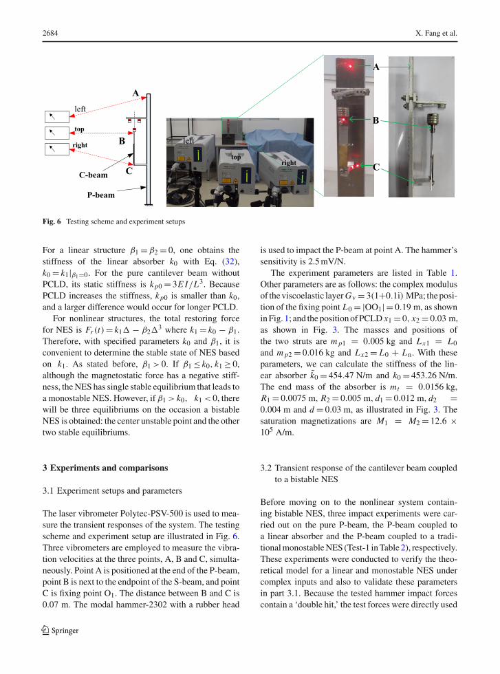
The laser vibrometer Polytec-PSV-500 is used to mea-sure the transient responses of the system. The testingscheme and experiment setup are illustrated in Fig. 6.Three vibrometers are employed to measure the vibra-tion velocities at the three points, A, B and C, simulta-neously. Point A is positioned at the end of the P-beam,point B is next to the endpoint of the S-beam, and pointC is fixing point O1. The distance between B and C is0.07 m. The modal hammer-2302 with a rubber head
is used to impact the P-beam at point A. The hammer’ssensitivity is 2.5mV/N.
The experiment parameters are listed in Table 1.Other parameters are as follows: the complex modulusof theviscoelastic layerGv = 3(1+0.1i) MPa; theposi-tion of the fixing point L0 = |OO1| = 0.19 m, as showninFig. 1; and thepositionofPCLD x1 = 0, x2 = 0.03 m,as shown in Fig. 3. The masses and positions ofthe two struts are mp1 = 0.005 kg and Lx1 = L0
and mp2 = 0.016 kg and Lx2 = L0 + Ln. With theseparameters, we can calculate the stiffness of the lin-ear absorber k0 = 454.47 N/m and k0 = 453.26 N/m.The end mass of the absorber is mt = 0.0156 kg,R1 = 0.0075 m, R2 = 0.005 m, d1 = 0.012 m, d2 =0.004 m and d = 0.03 m, as illustrated in Fig. 3. Thesaturation magnetizations are M1 = M2 = 12.6 ×10⁵ A/m.
3.2 Transient response of the cantilever beam coupledto a bistable NES
Before moving on to the nonlinear system contain-ing bistable NES, three impact experiments were car-ried out on the pure P-beam, the P-beam coupled toa linear absorber and the P-beam coupled to a tradi-tionalmonostableNES (Test-1 inTable 2), respectively.These experiments were conducted to verify the theo-retical model for a linear and monostable NES undercomplex inputs and also to validate these parametersin part 3.1. Because the tested hammer impact forcescontain a ‘double hit,’ the test forces were directly used
123
Highly efficient continuous bistable nonlinear energy sink 2685
Table 1 Experiment parameters
Material properties Primary beam (P-beam) Base beam of absorber Constrained layer Viscoelastic layer
Elastic modulus (GPa) 70 (1 + 0.01i) 70 (1 + 0.01i) 49 (1 + 0.001i) –
Density ρ (kg/m3) 2700 2700 7500 1000
Height h (m) 0.005 0.001 0.0004 0.00054
Length (m) 0.35 0.08 0.03 0.03
Width b (m) 0.04 0.012 0.012 0.012
Table 2 Additional experimental parameters for nonlinearrestoring force
D (mm) β1 (N/m) β2 × 10⁶ (N/m3) k1 (N/m)
Test-1 11.2 255.83 −0.13654 197.43
Test-2 8.0 551.80 −2.8311 −98.740
Test-3 6.9 715.71 −3.6302 −262.46
as the input signals in the theoretical simulations toachieve a better comparison between the tests and the-oretical results. These results are presented in Supple-mentary Materials.
With the same k0, themodulation of distance D gen-erates different nonlinear dynamic properties. Addi-tional parameters of the tests are provided in Table 2.The first test is monostable NES, and the second andthe third tests are bistable NESs with different first-order stiffness k1. The fourth-order complex Gaussianwavelets are adopted in wavelet transforms (WTs).
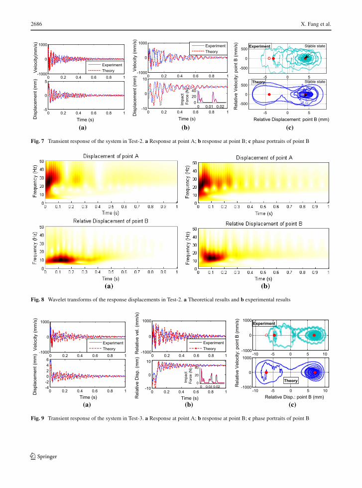
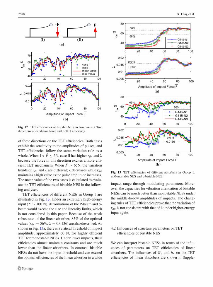
Figures 7 and 8 illustrate the transient responses ofthe system inTest-2 under the impact amplitude of 40Nincluding the ‘double hit’ effects (as seen in the smalliconography in Fig. 7b. As shown in Fig. 7a, b, theexperimental and theoretical results are consistent inthe initial stage; in the consequent motion, althoughthey have differences in certain time ranges becauseof the frequency difference, the oscillating trends inthe time domain and WTs are the same. A high-orderresponse appears in the continuousNES, but it is not themajor component. As seen in the theoretical phase dia-gram of point B, the distance between the two symmet-rical stable equilibriums is 8.4 mm. However, the un-centering installation errors in the experiments causethe experimental phase diagram of point B to be asym-metrical. The bistable NES generates two jumps fromone stable equilibrium to another one with a subhar-monic frequency. This paper defines this phenomenonas the stable state transition. Combining the results of
WTs, the high-amplitude transition generates a 1:2 sub-harmonic nonlinear beating (during 0–0.3s) that resultsin highly efficient TET with a simultaneously rapiddissipation of energy. After the transition, motionsof bistable NES are captured by one stable equilib-rium.Additionally, vibrations in the primary systemarelargely weakened, and the 2:3 subharmonic resonancecapture takes places to transfer energy to NES contin-uously. The subharmonic nonlinear beating observedin experiments is different from the high-frequencynonlinear beating occurring in traditional monostableNES.
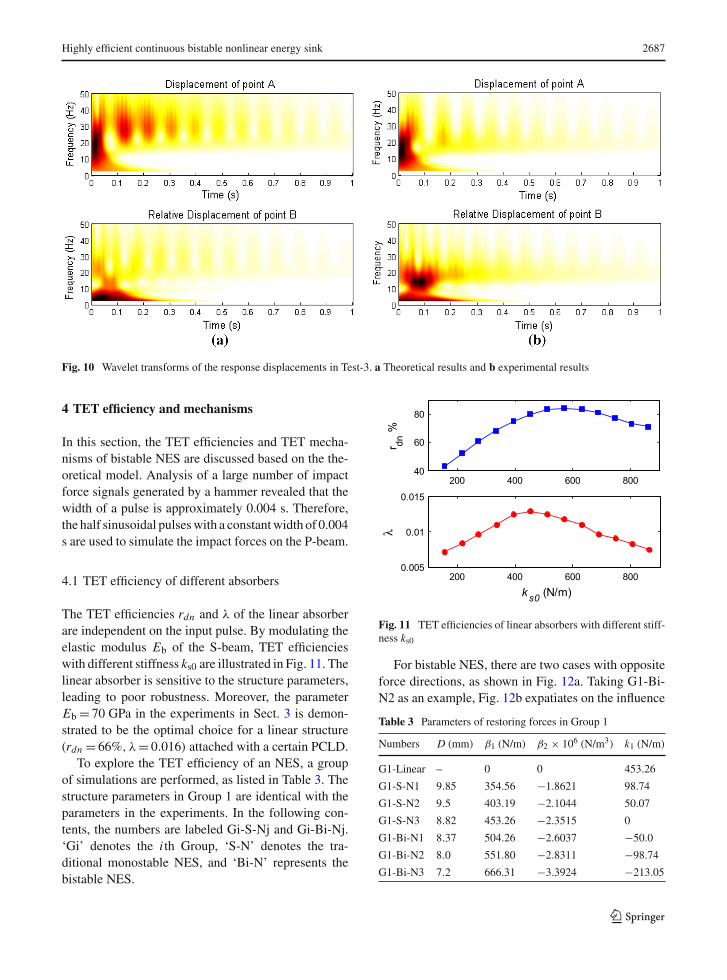
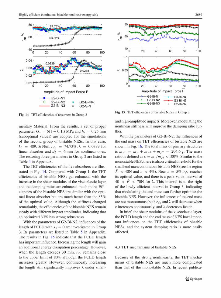
In Test-3, both |k1| and |β2| are increased, but thewave of the impact force is similar to that of Test-2.As shown in Fig. 9a–c and Fig. 10a, b, the theoreti-cal results exactly depict the vibration attenuation lawsin this experiment. In (a) (b) (c) Figure 9c, the un-centering error still exists in the measurements. In thiscase, the distance between the two stable equilibriumsincreases to 13.8 mm, while the energy needed for theabsorber to transition from one stable state to anotherone also increases. Therefore, the bistable NES in Test-3 only generates one transition under a similar impact.In the WTs plots, obvious components lower than 10Hz during 0–0.2 s caused by the nonzero mean valuerather than the vibration are observed. After a tran-sient 1:1 resonance capture, energy localized in NESincreases enough to drive the NES to transition andsimultaneously bring a strongnonlinear beating follow-ing the 2:3 subharmonic orbit. During 0.3–1 s, continu-ous nonlinear beatings take place following the 1:1 res-onance orbit. These nonlinear beatings generate highlyefficient TET to suppress the vibration of the primarystructure.
The analyses above indicate that the theoreticalmodel established for continuous NES coupled to theelastic beam can accurately describe the dynamics of alinear system,monostableNES and bistableNESundercomplex impacts.
123
2686 X. Fang et al.
0 0.2 0.4 0.6 0.8 1-1000
0
1000
Vel
ocity
(mm
/s)
ExperimentTheory
0 0.2 0.4 0.6 0.8 1-5
0
5
Time (s)Dis
plac
emen
t (m
m)
0 0.2 0.4 0.6 0.8 1-1000
0
1000
Vel
ocity
(mm
/s)
ExperimentTheory
0 0.2 0.4 0.6 0.8 1-10
0
10
Time (s)
Dis
plac
emen
t (m
m)
0 0.01 0.020
2040
Impa
ct
F
orce
(N)
-5 0 5
-500
0
500Experiment Stable state
-5 0 5
-500
0
500
Relative Displacement: point B (mm)
Rel
ativ
e V
eloc
ity: p
oint
B (m
m/s
)
Theory Stable state
(a) (b) (c)
Fig. 7 Transient response of the system in Test-2. a Response at point A; b response at point B; c phase portraits of point B
Fig. 8 Wavelet transforms of the response displacements in Test-2. a Theoretical results and b experimental results
0 0.2 0.4 0.6 0.8 1-1000
0
1000
Vel
ocity
(mm
/s)
ExperimentTheory
0 0.2 0.4 0.6 0.8 1-4-20246
Time (s)
Dis
plac
emen
t (m
m) 0 0.2 0.4 0.6 0.8 1
-1000
0
1000
Rel
ativ
e ve
l. (m
m/s
)
ExperimentTheory
0 0.2 0.4 0.6 0.8 1-10
0
10
Time (s)Rel
ativ
e D
isp.
(mm
)
0 0.01 0.020
20
40
Impa
ct
Forc
e (N
)
-10 -5 0 5 10-1000
0
1000
Rel
ativ
e V
eloc
ity: p
oint
B (m
m/s
)
Experiment
-10 -5 0 5 10-1000
0
1000
Relative Disp.: point B (mm)
Theory
(a) (b) (c)
Fig. 9 Transient response of the system in Test-3. a Response at point A; b response at point B; c phase portraits of point B
123
Highly efficient continuous bistable nonlinear energy sink 2687
Fig. 10 Wavelet transforms of the response displacements in Test-3. a Theoretical results and b experimental results
4 TET efficiency and mechanisms
In this section, the TET efficiencies and TET mecha-nisms of bistable NES are discussed based on the the-oretical model. Analysis of a large number of impactforce signals generated by a hammer revealed that thewidth of a pulse is approximately 0.004 s. Therefore,the half sinusoidal pulseswith a constantwidth of 0.004s are used to simulate the impact forces on the P-beam.
4.1 TET efficiency of different absorbers
The TET efficiencies rdn and λ of the linear absorberare independent on the input pulse. By modulating theelastic modulus Eb of the S-beam, TET efficiencieswith different stiffness ks0 are illustrated in Fig. 11. Thelinear absorber is sensitive to the structure parameters,leading to poor robustness. Moreover, the parameterEb = 70 GPa in the experiments in Sect. 3 is demon-strated to be the optimal choice for a linear structure(rdn = 66%, λ = 0.016) attached with a certain PCLD.
To explore the TET efficiency of an NES, a groupof simulations are performed, as listed in Table 3. Thestructure parameters in Group 1 are identical with theparameters in the experiments. In the following con-tents, the numbers are labeled Gi-S-Nj and Gi-Bi-Nj.‘Gi’ denotes the i th Group, ‘S-N’ denotes the tra-ditional monostable NES, and ‘Bi-N’ represents thebistable NES.
200 400 600 80040
60
80
r dn %
200 400 600 8000.005
0.01
0.015
ks0 (N/m)
λ
Fig. 11 TET efficiencies of linear absorbers with different stiff-ness ks0
For bistable NES, there are two cases with oppositeforce directions, as shown in Fig. 12a. Taking G1-Bi-N2 as an example, Fig. 12b expatiates on the influence
Table 3 Parameters of restoring forces in Group 1
Numbers D (mm) β1 (N/m) β2 × 10⁶ (N/m3) k1 (N/m)
G1-Linear – 0 0 453.26
G1-S-N1 9.85 354.56 −1.8621 98.74
G1-S-N2 9.5 403.19 −2.1044 50.07
G1-S-N3 8.82 453.26 −2.3515 0
G1-Bi-N1 8.37 504.26 −2.6037 −50.0
G1-Bi-N2 8.0 551.80 −2.8311 −98.74
G1-Bi-N3 7.2 666.31 −3.3924 −213.05
123
2688 X. Fang et al.
F-F
(I)(a)
(b)
(II)
0 20 40 60 80 10040
50
60
70
r dn % case I
case IImean valuemax value
0 20 40 60 80 100
0.01
0.015
0.02
Amplitude of Impact Force F
λ
Fig. 12 TET efficiencies of bistable NES in two cases. a Twodirections of excitation force and b TET efficiency
of force directions on the TET efficiencies. Both casesexhibit the sensitivity to the amplitudes of pulses, andTET efficiencies follow the same variation rule as awhole. When 1< F ≤ 5N, case II has higher rdn and λ
because the force in this direction excites a more effi-cient TET mechanism. When F > 65N, the variationtrends of rdn and λ are different; λ decreases while rdnmaintains a high value as the pulse amplitude increases.The mean value of the two cases is calculated to evalu-ate the TET efficiencies of bistable NES in the follow-ing analyses.
TET efficiencies of different NESs in Group 1 areillustrated in Fig. 13. Under an extremely high-energyinput (F > 100 N), deformations of the P-beam and S-beam would exceed the size and linearity limits, whichis not considered in this paper. Because of the weakrobustness of the linear absorber, 85% of the optimalvalues (rdn = 56%, λ = 0.0136) are also described.Asshown in Fig. 13a, there is a critical threshold of impactamplitude, approximately 60 N, for highly efficientTET for monostable NESs. Under lower impacts, theirefficiencies almost maintain constants and are muchlower than the linear absorbers. In contrast, bistableNESs do not have the input threshold and can exceedthe optimal efficiencies of the linear absorber in a wide
0 20 40 60 80 100
40
60
80
r dn %
66%
56%G1-S-N1G1-S-N2G1-S-N3
0 20 40 60 80 1000.005
0.01
0.015
0.02
Amplitude of Impact Force F
Amplitude of Impact Force F
λ
0.016
0.0136
0 20 40 60 80 100
40
60
80
r dn %
66%
56%
0 20 40 60 80 1000.005
0.01
0.015
0.02
λ
0.0160.0136
G1-Bi-N1G1-Bi-N2G1-Bi-N3
(a)
(b)
Fig. 13 TET efficiencies of different absorbers in Group 1.a Monostable NES and b bistable NES
impact range through modulating parameters. More-over, the capacities for vibration attenuation of bistableNESs can be much better than monostable NESs underthe middle-to-low amplitudes of impacts. The chang-ing rules of TET efficiencies prove that the variation ofrdn is not consistent with that of λ under higher-energyinput again.
4.2 Influences of structure parameters on TETefficiencies of bistable NES
We can interpret bistable NESs in terms of the influ-ences of parameters on TET efficiencies of linearabsorbers. The influences of Gv and hv on the TETefficiencies of linear absorbers are shown in Supple-
123
Highly efficient continuous bistable nonlinear energy sink 2689
0 20 40 60 80 10040
60
80r dn
%74.73%
63.52%
0 20 40 60 80 1000.01
0.02
0.03
0.04
Amplitude of Impact Force F
λ
0.0339
0.0288
G2-Bi-N1G2-Bi-N2G2-Bi-N3
G2-Bi-N4G2-S-N
Fig. 14 TET efficiencies of absorbers in Group 2
mentary Material. From the results, a set of properparameter Gv = 6(1 + 0.1i) MPa and hv = 0.25 mm(suboptimal values) are adopted for the simulationsof the second group of bistable NESs. In this case,k0 = 489.16 N/m, rdn = 74.73%, λ = 0.0339 forlinear absorber and d2 = 6 mm for nonlinear ones.The restoring force parameters in Group 2 are listed inTable 4 in Appendix.
The TET efficiencies of the five absorbers are illus-trated in Fig. 14. Compared with Group 1, the TETefficiencies of bistable NESs get enhanced with theincrease in the shear modulus of the viscoelastic layerand the damping ratios are enhanced much more. Effi-ciencies of the bistable NES are similar with the opti-mal linear absorber but are much better than the 85%of the optimal value. Although the stiffness changedremarkably, the efficiencies of the bistable NES remainsteadywith different impact amplitudes, indicating thatan optimized NES has strong robustness.
With the parameters of G2-Bi-N2, influences of thelength of PCLD with x1 = 0 are investigated in Group3. Its parameters are listed in Table 5 in Appendix.The results in Fig. 15 indicate that the PCLD lengthhas important influence. Increasing the length will gainan additional energy dissipation percentage. However,when the length exceeds 30 mm, rdn remains closeto the upper limit of 80% although the PCLD lengthincreases greatly. However, continuously increasingthe length still significantly improves λ under small-
0 20 40 60 80 10040
60
80
r dn %
0 20 40 60 80 1000
0.05
0.1
Amplitude of Impact Force F
λ
G3-Bi-N1G3-Bi-N2G3-Bi-N3
G3-Bi-N4G3-Bi-N5G2-Bi-N2
Fig. 15 TET efficiencies of bistable NESs in Group 3
and high-amplitude impacts.Moreover,modulating thenonlinear stiffness will improve the damping ratio fur-ther.
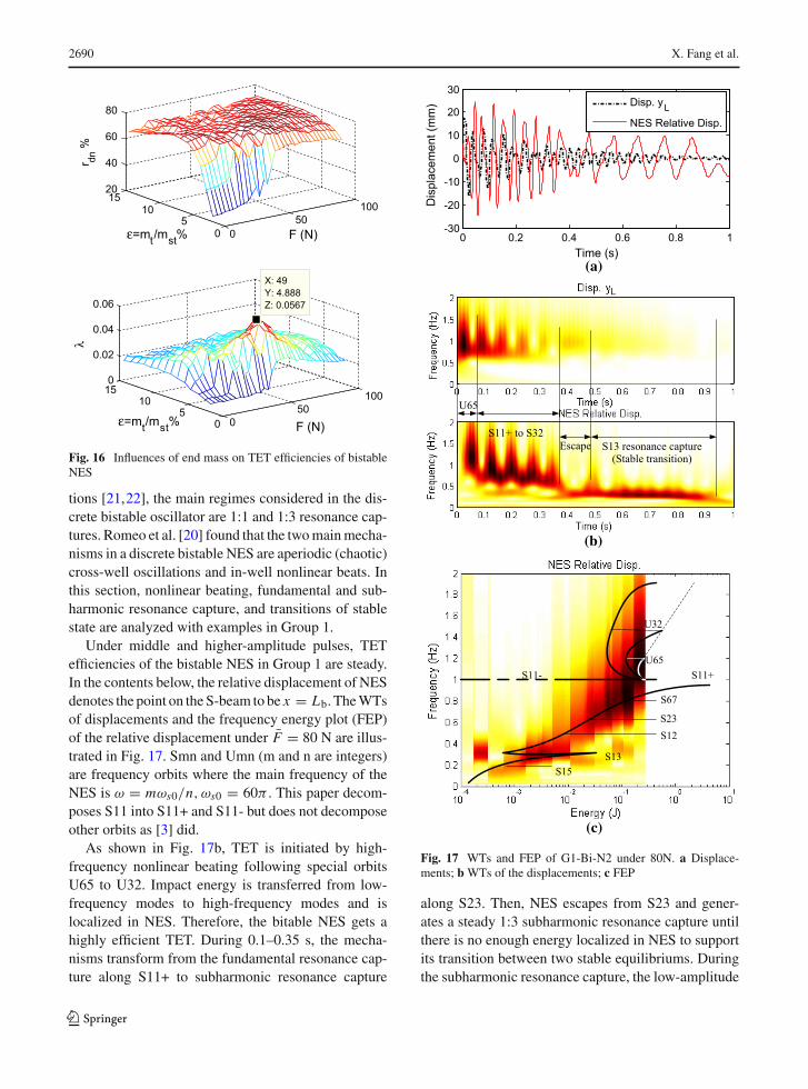
With the parameters of G2-Bi-N2, the influences ofthe end mass on TET efficiencies of bistable NES areshown in Fig. 16. The total mass of primary structuresis mpt = mp + mp1 + mp2 = 204.6 g. The massratio is defined as ε = mt/mpt × 100%. Similar to themonostableNES, there is also a critical threshold for thesmall endmass continuous bistableNES (see the regionF < 40N and ε < 4%). Near ε = 5%, rdn reachesits optimal value, and there is a peak-value interval of40 < F < 70N for λ. This interval is to the rightof the lowly efficient interval in Group 3, indicatingthat modulating the end mass can further optimize thebistable NES. However, the influences of the end massare not monotonous; both rdn and λwill decrease whenε increases continuously, and λ decreases faster.
In brief, the shear modulus of the viscoelastic layer,the PCLD length and the end mass of NES have impor-tant influences on the TET efficiencies of bistableNESs, and the system damping ratio is more easilyaffected.
4.3 TET mechanisms of bistable NES
Because of the strong nonlinearity, the TET mecha-nisms of bistable NES are much more complicatedthan that of the monostable NES. In recent publica-
123
2690 X. Fang et al.
050
100
05
101520
40
60
80
F (N)ε=mt/mst %
r dn %
050
100
05
10150
0.02
0.04
0.06
F (N)
X: 49Y: 4.888Z: 0.0567
ε=mt/mst%
λ
Fig. 16 Influences of end mass on TET efficiencies of bistableNES
tions [21,22], the main regimes considered in the dis-crete bistable oscillator are 1:1 and 1:3 resonance cap-tures. Romeo et al. [20] found that the twomainmecha-nisms in a discrete bistable NES are aperiodic (chaotic)cross-well oscillations and in-well nonlinear beats. Inthis section, nonlinear beating, fundamental and sub-harmonic resonance capture, and transitions of stablestate are analyzed with examples in Group 1.
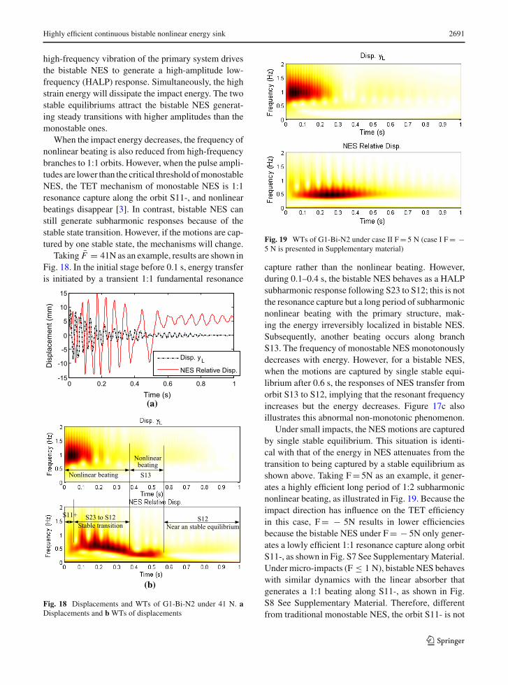
Under middle and higher-amplitude pulses, TETefficiencies of the bistable NES in Group 1 are steady.In the contents below, the relative displacement of NESdenotes the point on the S-beam to be x = Lb. TheWTsof displacements and the frequency energy plot (FEP)of the relative displacement under F = 80 N are illus-trated in Fig. 17. Smn and Umn (m and n are integers)are frequency orbits where the main frequency of theNES is ω = mωs0/n, ωs0 = 60π . This paper decom-poses S11 into S11+ and S11- but does not decomposeother orbits as [3] did.
As shown in Fig. 17b, TET is initiated by high-frequency nonlinear beating following special orbitsU65 to U32. Impact energy is transferred from low-frequency modes to high-frequency modes and islocalized in NES. Therefore, the bitable NES gets ahighly efficient TET. During 0.1–0.35 s, the mecha-nisms transform from the fundamental resonance cap-ture along S11+ to subharmonic resonance capture
Escape S13 resonance capture(Stable transition)
U65
S11+ to S32
S11-
U32
U65S11+
S67
S23S12
S13S15
0 0.2 0.4 0.6 0.8 1-30
-20
-10
0
10
20
30
Time (s)
Dis
plac
emen
t (m
m) Disp. yL
NES Relative Disp.
(a)
(b)
(c)
Fig. 17 WTs and FEP of G1-Bi-N2 under 80N. a Displace-ments; bWTs of the displacements; c FEP
along S23. Then, NES escapes from S23 and gener-ates a steady 1:3 subharmonic resonance capture untilthere is no enough energy localized in NES to supportits transition between two stable equilibriums. Duringthe subharmonic resonance capture, the low-amplitude
123
Highly efficient continuous bistable nonlinear energy sink 2691
high-frequency vibration of the primary system drivesthe bistable NES to generate a high-amplitude low-frequency (HALP) response. Simultaneously, the highstrain energy will dissipate the impact energy. The twostable equilibriums attract the bistable NES generat-ing steady transitions with higher amplitudes than themonostable ones.
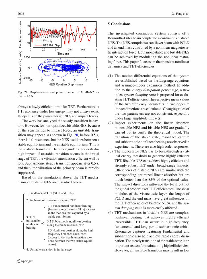
When the impact energy decreases, the frequency ofnonlinear beating is also reduced from high-frequencybranches to 1:1 orbits. However, when the pulse ampli-tudes are lower than the critical threshold ofmonostableNES, the TET mechanism of monostable NES is 1:1resonance capture along the orbit S11-, and nonlinearbeatings disappear [3]. In contrast, bistable NES canstill generate subharmonic responses because of thestable state transition. However, if the motions are cap-tured by one stable state, the mechanisms will change.
Taking F = 41N as an example, results are shown inFig. 18. In the initial stage before 0.1 s, energy transferis initiated by a transient 1:1 fundamental resonance
Nonlinear beating
S23 to S12Stable transition
S11+
Nonlinearbeating
S12Near an stable equilibrium
S13
0 0.2 0.4 0.6 0.8 1-15
-10
-5
0
5
10
15
(a)
(b)
Time (s)
Dis
plac
emen
t (m
m)
Disp. yL
NES Relative Disp.
Fig. 18 Displacements and WTs of G1-Bi-N2 under 41 N. aDisplacements and b WTs of displacements
Fig. 19 WTs of G1-Bi-N2 under case II F= 5 N (case I F= −5 N is presented in Supplementary material)
capture rather than the nonlinear beating. However,during 0.1–0.4 s, the bistable NES behaves as a HALPsubharmonic response following S23 to S12; this is notthe resonance capture but a long period of subharmonicnonlinear beating with the primary structure, mak-ing the energy irreversibly localized in bistable NES.Subsequently, another beating occurs along branchS13. The frequency of monostable NES monotonouslydecreases with energy. However, for a bistable NES,when the motions are captured by single stable equi-librium after 0.6 s, the responses of NES transfer fromorbit S13 to S12, implying that the resonant frequencyincreases but the energy decreases. Figure 17c alsoillustrates this abnormal non-monotonic phenomenon.
Under small impacts, the NES motions are capturedby single stable equilibrium. This situation is identi-cal with that of the energy in NES attenuates from thetransition to being captured by a stable equilibrium asshown above. Taking F= 5N as an example, it gener-ates a highly efficient long period of 1:2 subharmonicnonlinear beating, as illustrated in Fig. 19. Because theimpact direction has influence on the TET efficiencyin this case, F= − 5N results in lower efficienciesbecause the bistable NES under F= − 5N only gener-ates a lowly efficient 1:1 resonance capture along orbitS11-, as shown in Fig. S7 See SupplementaryMaterial.Under micro-impacts (F ≤ 1 N), bistable NES behaveswith similar dynamics with the linear absorber thatgenerates a 1:1 beating along S11-, as shown in Fig.S8 See Supplementary Material. Therefore, differentfrom traditional monostable NES, the orbit S11- is not
123
2692 X. Fang et al.
0 0.2 0.4 0.6 0.8 1
-10
0
10
Dis
plac
emen
t (m
m)
Time (s)
Disp. yL
NES Rel. Disp.
-15 -10 -5 0 5 10 15-2000
0
2000
NES Relative Disp. (mm)Rel
ativ
e Ve
loci
ty (m
m/s
)
Fig. 20 Displacements and phase diagram of G1-Bi-N2 forF= − 43 N
always a lowly efficient orbit for TET. Furthermore, a1:1 resonance under low energy may not always exist.It depends on the parameters of NES and impact forces.
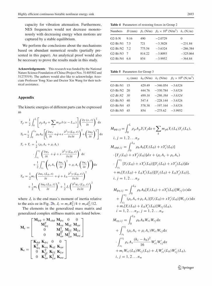
The work has analyzed the steady transition behav-iors.However, for non-optimizedbistableNES, becauseof the sensitivities to impact force, an unstable tran-sition may appear. As shown in Fig. 20, before 0.5 s,there is 1:1 resonance, but the NES oscillates between astable equilibrium and the unstable equilibrium. This isthe unstable transition. Therefore, under amoderate-to-high impact, if unstable transition occurs in the initialstage of TET, the vibration attenuation efficient will below. Subharmonic steady transition appears after 0.5 s,and then, the vibration of the primary beam is rapidlysuppressed.
Based on the simulations above, the TET mecha-nisms of bistable NES are classified below.
1. Fundamental TET (S11+ and S11-)
3.1 Fundamental nonlinear beating (beating along the orbit S11-). Occurs in the motions that captured by a stable equilibrium
2. Subharmonic resonance capture TET
3.2 Subharmonic nonlinear beating along the branches Smn, m<n
3.3 Nonlinear beating along the high frequency branches Umn, m≥n. (occurs in the steady transition mo-tions between the two stable equilib-riums)
4. Unstable transition in initial stage
3. TET initiated by nonlinear beating
5 Conclusions
The investigated continuous system consists of aBernoulli–Euler beam coupled to a continuous bistableNES.TheNEScomprises a cantilever beamwithPCLDand an end mass controlled by a nonlinear magnetosta-tic interaction force.Bothmonostable and bistableNEScan be achieved by modulating the nonlinear restor-ing force. This paper focuses on the transient nonlineardynamics and TET efficiencies.
(1) The motion differential equations of the systemare established based on the Lagrange equationsand assumed-modes expansion method. In addi-tion to the energy dissipation percentage, a newindex system damping ratio is proposed for evalu-atingTET efficiencies. The respectivemean valuesof the two efficiency parameters in two oppositeimpact directions are calculated. Changing rules ofthe two parameters are not consistent, especiallyunder large amplitude impacts.
(2) Impact experiments on the linear absorber,monostable NES and bistable NES are graduallycarried out to verify the theoretical model. Thetransition of the stable state, resonance captureand subharmonic nonlinear beating are observed inexperiments. There are also high-order responses.
(3) The monostable NES has to breakthrough a crit-ical energy threshold to generate highly efficientTET.BistableNEScan achievehighly efficient andstrongly robust TET under broad-range impacts.Efficiencies of bistable NESs are similar with thecorresponding optimized linear absorber but aremuch better than the 85% of the optimal value.The impact directions influence the local but notthe global properties ofTETefficiencies. The shearmodulus of the viscoelastic layer, the length ofPCLD and the end mass have great influences onthe TET efficiencies of bistable NESs, and the sys-tem damping ratio is more easily affected.
(4) TET mechanisms in bistable NES are complex;nonlinear beating that achieves highly efficientirreversible TET can occur in high-frequency,fundamental and long-period subharmonic orbits.Resonance captures featuring fundamental andsubharmonic also help achieve rapid energy dissi-pation. The steady transition of the stable state is animportant reason formaintaining high efficiencies.However, an unstable transition may result in low
123
Highly efficient continuous bistable nonlinear energy sink 2693
capacity for vibration attenuation. Furthermore,NES frequencies would not decrease monoto-nously with decreasing energy when motions arecaptured by a stable equilibrium.
We perform the conclusions about the mechanismsbased on abundant numerical results (partially pre-sented in this paper). An analytical proof would alsobe necessary to prove the results made in this study.
Acknowledgements This research was funded by the NationalNature Science Foundation of China (Project Nos. 51405502 and51275519). The authors would also like to acknowledge Asso-ciate Professor Yong Xiao and Doctor Xin Wang for their tech-nical assistance.
Appendix
The kinetic energies of different parts can be expressedas
Tp = 1
2
∫ L
0
[ρp Ap +
∑i
m pi δ (x − Lxi )
](∂y (x, t)
∂t
)2
dx
Tb = 1
2
∫ Lb
0ρb Ab
[(∂wr
∂t+ϕ+x
∂2y (L0, t)
∂x∂t
)2
+(
∂ub∂t
)2]dx
Tv + Tc = 1
2(ρv Av + ρc Ac)
·∫ x2
x1
(∂wr
∂t+ ϕ + x
∂2y (L0, t)
∂x∂t
)2
dx
+ 1
2
∫ x2
x1
(ρv Av
(∂uv
∂t
)2
+ ρc Ac
(∂uc∂t
)2)dx
Tm = 1
2mt
(∂wr (Lb, t)
∂t+ ϕ + Lb
∂2y (L0, t)
∂x∂t
)2
+ 1
2mt
(∂ub (Lb, t)
∂t
)2
+ 1
2Jt
(∂2wr (Lb, t)
∂x∂t
)2
where Jt is the end mass’s moment of inertia relativeto the axis oz in Fig. 2b, Jt = mt R2
1/4 + mtd21/12.The elements in the generalized mass matrix and
generalized complex stiffness matrix are listed below.
Me =
⎡⎢⎢⎣Mφφ + Mcφφ Mφη 0 0
MTφη Mηη Mηξ Mηα
0 MTηξ Mξξ Mξα
0 MTηα MT
ξα Mαα
⎤⎥⎥⎦
Ke =
⎡⎢⎢⎣Kφφ Kφη 0 0KT
φη Kηη Kηξ Kηα
0 KTηξ Kξξ Kξα
0 KTηα KT
ξα Kαα
⎤⎥⎥⎦
Table 4 Parameters of restoring forces in Group 2
Numbers D (mm) β1 (N/m) β2 × 10⁶ (N/m3) k1 (N/m)
G2-S-N 9.16 490 −2.0729 0
G2-Bi-N1 7.5 721 −3.3828 −231.84
G2-Bi-N2 7.2 775.54 −3.6324 −286.384
G2-Bi-N3 7 814.22 −3.8093 −325.064
G2-Bi-N4 6.8 854 −3.9952 −364.84
Table 5 Parameters for Group 3
x2 (mm) k0 (N/m) k1 (N/m) β2 × 10⁶ (N/m3)
G3-Bi-N1 15 429.49 −346.054 −3.6324
G3-Bi-N2 20 444.76 −330.784 −3.6324
G2-Bi-N2 30 489.16 −286.384 −3.6324
G3-Bi-N3 40 547.4 −228.144 −3.6324
G3-Bi-N4 45 578.38 −197.164 −3.6324
G3-Bi-N5 45 854 −275.62 −3.9952
Mφφ,i j =∫ L
0ρp ApYiY jdx+
∑k
m pkYi (Lk)Y j (Lk),
i, j = 1, 2 . . . n p
Mcφφ,i j =∫ Lb
0ρb Ab[Yi (L0) + xY ′
i (L0)]· [Y j (L0) + xY ′
j (L0)]dx + (ρc Ac + ρvAv)
·∫ x2
x1[Yi (L0) + xY ′
i (L0)][Y j (L0) + xY ′j (L0)]dx
+mt [Yi (L0) + LbY′i (L0)][Y j (L0) + LbY
′j (L0)],
i, j = 1, 2 . . . n p
Mφη,i j =∫ Lb
0ρb Ab[Yi (L0) + xY ′
i (L0)]Wr j (x)dx
+∫ x2
x1(ρvAv+ρc Ac)[Yi (L0)+ xY ′
i (L0)]Wr j (x)dx
+mt [Yi (L0) + LbY ′i (L0)]Wr j (Lb),
i = 1, 2 . . . n p, j = 1, 2 . . . nw
Mηη,i j =∫ Lb
0ρb AbWriWr jdx
+∫ x2
x1(ρvAv + ρc Ac)WriWr jdx
·∫ x2
x1ρvAv
(hc − hb)2
16W ′
riW′r jdx
+mtWri (Lb)Wr j (Lb) + JtW′ri (Lb)W
′r j (Lb),
i, j = 1, 2 . . . nw
123
2694 X. Fang et al.
Mηξ,i j = 1
8
∫ x2
x1ρvAv(hc − hb)W
′riUbjdx,
i = 1, 2 . . . nw, j = 1, 2 . . . nb
Mηα,i j = 1
8
∫ x2
x1ρvAv(hc − hb)W
′riUcjdx,
i = 1, 2 . . . nw, j = 1, 2 . . . nc
Mξξ,i j =∫ Lb
0ρb AbUbiUbjdx
+ 1
4
∫ x2
x1ρvAvUbiUbjdx + mtUbi (Lb)Ubj (Lb),
i, j = 1, 2 . . . nb
Mξα,i j = 1
4
∫ x2
x1ρvAvUbiUcjdx,
i = 1, 2 . . . nb, j = 1, 2 . . . nc
Mαα,i j =∫ x2
x1
(ρc Ac + 1
4ρvAv
)UciUcjdx,
i, j = 1, 2 . . . ncKφφ,i j =∫ L
0Ep IpY
′′i Y
′′j dx
−β1(Y�i + LbY
′i
) (Y� j + LbY
′j
),
i, j = 1, 2 . . . n p
Kφη,i j = −β1(Y�i + LbY
′i
)Wr j (Lb),
i = 1, 2 . . . n p, j = 1, 2 . . . nw
Kηη,i j =∫ Lb
0Eb IbW
′′riW
′′r jdx +
∫ x2
x1Ec IcW
′′riW
′′r jdx
+∫ x2
x1
GvAv
h2vh2t W
′riW
′r jdx − β1Wri (Lb)Wr j (Lb),
i, j = 1, 2 . . . nw
Kηξ,i j = −∫ x2
x1
GvAv
h2vhtW
′riUbjdx,
i = 1, 2 . . . nw, j = 1, 2 . . . nb
Kηα,i j =∫ x2
x1
GvAv
h2vhtW
′riUcjdx,
i = 1, 2 . . . nw, j = 1, 2 . . . nc
Kξξ,i j =∫ Lb
0EbAbU
′biU
′bjdx+
∫ x2
x1
GvAv
h2vUbiUbjdx,
i, j = 1, 2 . . . nb
Kξα,i j = −∫ x2
x1
GvAv
h2vUbiUcjdx,
i = 1, 2 . . . nb, j = 1, 2 . . . nc
Kαα,i j =∫ x2
x1Ec AcU
′ciU
′cjdx+
∫ x2
x1
GvAv
h2vUciUcjdx,
i, j = 1, 2 . . . nc
Pi =⎧⎨⎩
(Y�i + LbY ′i ) f or i = 1, 2 . . . n p
Wri (Lb) f or i = n p + 1, . . . n p + nw
0 others
Mn =⎡⎣Mηη Mηξ Mηα
MTηξ Mξξ Mξα
MTηα MT
ξα Mαα
⎤⎦ ,
Kn =⎡⎣Kηη Kηξ Kηα
KTηξ Kξξ Kξα
KTηα KT
ξα Kαα
⎤⎦
References
1. Anubi, O.M., Crane III, C.D.: A new active variable stiff-ness suspension system using a nonlinear energy sink-basedcontroller. Vehicle Syst. Dyn. 51(10), 1588–1602 (2013)
2. Kremer, D., Liu, K.F.: A nonlinear energy sink with anenergy harvester: transient responses. J. Sound Vib. 333,4859–4880 (2014)
3. Lee, Y.S., Vakakis, A.F., Bergman, L.A., McFarland, D.M.,et al.: Passive non-linear targeted energy transfer and itsapplications to vibration absorption: a review. Proc. IMechE.Part K J. Multi-Body Dyn. 222(2), 77–134 (2007)
4. Gourdon, E., Lamarque, C.H., Pernot, S.: Contribution toefficiency of irreversible passive energy pumping with astrong nonlinear attachment. Nonlinear Dyn. 50, 793–808(2007)
5. Gendelman, O.V.: Transition of energy to a nonlinear local-ized mode in a highly asymmetric system of two oscillators.Nonlinear Dyn. 25, 237–253 (2001)
6. Vakakis, A.F.: Inducing passive nonlinear energy sinks invibrating systems. J. Vib. Acoust. 123, 324–332 (2001)
7. Vakakis, A.F., Gendelman, O.V.: Energy pumping in non-linear mechanical oscillators: Part II-resonance capture. J.Appl. Mech. 68, 42–48 (2001)
8. Vakakis, A.F., Gendelman, O.V., Bergman, L.A., McFar-land, D.M., Kerschen, G., Lee, Y.S.: Nonlinear TargetedEnergy Transfer in Mechanical and Structural Systems.Springer, Dordrecht (2008)
9. Lee, Y.S., et al.: Enhancing the robustness of aeroelasticinstability suppression using multi-degree-of-freedom non-linear energy sinks. AIAA J. 46, 1371–1394 (2008)
10. Sapsis, T.P., et al.: Effective stiffening anddamping enhance-ment of structureswith strongly nonlinear local attachments.J. Vib. Acoust. 134, 011016 (2012)
11. Quinn, D.D., et al.: Equivalent modal damping, stiffeningand energy exchanges in multi degree-of-freedom systemswith strongly nonlinear attachments. Proc. Inst. Mech. Eng.,Part K J. Multi-Body Dyn. 226(2), 122–146 (2012)
12. Gendelman, O.V., Sapsis, T., Vakakis, A.F., Bergman, L.A.:Enhanced passive targeted energy transfer in strongly non-linear mechanical oscillators. J. Sound Vib. 330, 1–8 (2011)
13. Gendelman,O.V., Sigalov, G.,Manevitch, L.I.: Dynamics ofan eccentric rotational nonlinear energy sink. J. Appl.Mech.79, 011012 (2012)
14. Sigalov, G., Gendelman, O.V., AL-Shudeifat, M.A.,Manevitch, L.I., Vakakis, A.F., Bergman, L.A.: Resonance
123
Highly efficient continuous bistable nonlinear energy sink 2695
captures and targeted energy transfers in an inertially-coupled rotational nonlinear energy sink. Nonlinear Dyn.69, 1693–1704 (2012)
15. Gendelman, O.V.: Analytic treatment of a system with avibro-impact nonlinear energy sink. J. Sound Vib. 331,4599–4608 (2012)
16. Karayannis, I., Vakakis, A.F., Georgiades, F.: Vibro-impactattachments as shock absorbers. Proc. IMechE. J. Mech.Eng. Sci. 222, 1899–1908 (2008)
17. Mohammad, A., Shudeifat, A.L.: Asymmetric magnet-based nonlinear energy sink. J. Comput. Nonlinear Dyn.10(1), 014502 (2014)
18. Wierschem, N.E.: Targeted Energy Transfer Using Nonlin-ear Energy Sinks for the Attenuation of Transient Loads onBuilding Structures. Ph.D. thesis (2014)
19. Mohammad, A., Shudeifat, A.L.: Highly efficient nonlinearenergy sink. Nonlinear Dyn. 76, 1905–1920 (2014)
20. Romeo, F., Manevitch, L.I., Bergman, L.A., Vakakis, A.:Transient and chaotic low-energy transfers in a system withbistable nonlinearity. Chaos 25, 053109 (2015)
21. Romeo, F., Sigalov, G., Bergman, L.A., Vakakis, A.F.:Dynamics of a linear oscillator coupled to a bistable lightattachment: numerical study. J. Comput. Nonlinear Dyn.10(1), 011007 (2015)
22. Manevitch, L.I., Sigalov, G., Romeo, F., Bergman, L.A.,Vakakis, A.: Dynamics of a linear oscillator coupled to abistable light attachment: analytical study. J. Appl. Mech.81(4), 041011 (2014)
23. Manevitch, L.I.: The description of localized normal modelsin a chain of nonlinear coupled oscillators using complexvariables. Nonlinear Dyn. 25, 95–109 (2001)
24. Farid, M., Gendelman, O.V.: Tuned pendulum as nonlinearenergy sink for broad energy range. J. Vib. Control (2015).doi:10.1177/1077546315578561
25. Cottone, F., Vocca, H., Gammaitoni, L.: Nonlinear energyharvesting. Phys. Rev. Lett. 102, 080601 (2009)
26. Jia, Y., Seshia, A.A.: Directly and parametrically excitedbi-stable vibration energy harvester for broadband oper-ation. Transducers (2013). doi:10.1109/Transducers.2013.6626801
27. Harne, R.L., Wang, K.W.: A review of the recent researchon vibration energy harvesting via bistable Systems. SmartMater. Struct. 22, 023001 (2013)
28. Tang, L.H., Yang, Y.W., Soh, C.K.: Improving functiona-lity of vibration energy harvesters using magnets.J. Intell. Mater. Syst. Struct. (2012). doi:10.1177/1045389X12443016
29. Gao, Y.J., Leng, Y.G., Fan, S.B., Lai, Z.H.: Studies on vibra-tion response and energy harvesting of elastic-supportedbistable piezoelectric cantilever beams. Acta Phys. Sin.63(9), 090501 (2014)
30. Vokoun, D., Beleggia, M., Heller, L., Sittner, P.: Magne-tostatic interactions and forces between cylindrical per-manent magnets. J. Magn. Magn. Mater. 321, 3758–3763(2009)
31. Vokoun, D., Beleggia, M., Heller, L.: Magnetic guns withcylindrical permanent magnets. J. Magn. Magn. Mater. 324,1715–1719 (2012)
32. Avvari, P.V., Tang, L.H., Yang, Y.W., Soh, C.K.: Enhan-cement of piezoelectric energy harvesting with multi-stablenonlinear vibrations. Proc. of SPIE (2013). doi:10.1117/12.2009560
33. Jones, D.I.G., et al.: Handbook of Viscoelastic VibrationDamping. Wiley, Chichester (2001)
34. Edward, J., Kerwin, M.: Damping of flexural waves by aconstrained viscoelastic layer. J. Acoust. Soc. Am. 31(7),952–962 (1959)
35. Plunkett, R., Lee, C.T.: Length optimization for constrainedviscoelastic layer damping. J.Acoust. Soc.Am. 48, 150–161(1970)
36. Hou, S.W., Jiao, Y.H., Wang, X., Chen, Z.B., Fan, Y.B.:Optimization of platewith partial constrained layer dampingtreatment for vibration and noise reduction. Appl. Mech.Mater. 138–139, 20–26 (2012)
37. Ling, Z., Ronglu, X., Yi, W., El-Sabbagh, A.: Topologyoptimization of constrained layer damping on plates usingmethod of moving asymptote (MMA) approach. Shock Vib.18(1), 221–244 (2011)
38. Kim, S.Y.: Topology Design Optimization for VibrationReduction: Reducible Design Variable Method. Queen’sUniversity, Kingston (2011)
39. Mead, D.J., Ae, D.C.: The effect of a damping compound onjet-efflux excited vibrations: an article in two parts present-ing theory and results of experimental investigation. Part I.The structural damping due to the compound. Aircr. Eng.Aerosp. Technol. 32, 64–72 (1960)
40. Mead, D.J.: A comparison of some equations for the flexuralvibration of damped sandwich beams. J. SoundVib. 83, 363–377 (1982)
41. Shi, H.M., Huang, Q.B.: Vibration Systems: Analyzing,Modeling, Testing, Controlling. 3rd edn. Huazhong Univer-sity of science and Technology Press (2014), in Chinese
123