Embed Size (px)
Citation preview
Highly sensitive and selective odorant sensor usingliving cells expressing insect olfactory receptorsNobuo Misawaa,b,1, Hidefumi Mitsunob,c,1, Ryohei Kanzakic, and Shoji Takeuchia,b,2
aInstitute of Industrial Science, University of Tokyo, 4-6-1 Komaba, Meguro-ku, Tokyo 153-8505, Japan; bLife Bio Electro-mechanical Autonomous NanoSystems (Life BEANS) Center, The BEANS Project, University of Tokyo, 4-6-1 Komaba, Meguro-ku, Tokyo 153-8505, Japan; and cResearch Center forAdvanced Science and Technology, University of Tokyo, 4-6-1 Komaba, Meguro-ku, Tokyo 153-8904, Japan
Edited by Katepalli R. Sreenivasan, New York University, New York, NY, and approved July 20, 2010 (received for review March 31, 2010)
This paper describes a highly sensitive and selective chemicalsensor using living cells (Xenopus laevis oocytes) within a portablefluidic device. We constructed an odorant sensor whose sensitivityis a few parts per billion in solution and can simultaneously distin-guish different types of chemicals that have only a slight differencein double bond isomerism or functional group such as ─OH, ─CHOand ─Cð═OÞ─. We developed a semiautomatic method to installcells to the fluidic device and achieved stable and reproducibleodorant sensing. In addition, we found that the sensor workedfor multiple-target chemicals and can be integrated with a roboticsystemwithout any noise reduction systems. Our developed sensoris compact and easy to replace in the system. We believe that thesensor can potentially be incorporated into a portable system formonitoring environmental and physical conditions.
fluidic channel ∣ odorant receptor ∣ robot ∣ Xenopus oocyte
Various approaches to developing artificial odorant detectorshave been reported. Presently, chemical sensors are mainly
fabricated based on metal-oxide semiconductors, quartz crystalmicrobalances, surface plasmon resonators, or surface acousticwave devices (1–5). These sensors were developed with the aimof achieving good portability while demonstrating high sensitivityand selectivity, in order that they find application as mobilechemical sensors in the monitoring of environmental or physicalconditions (6). However, it has been difficult to develop an ade-quate chemical sensor that combines all of these properties.
Natural living systems, on the other hand, show reactions un-ique to several chemicals at the molecular level. Such systems areable to distinguish between different chemical moieties found inodorants and tastants (7, 8). The specificity of an organism’s re-sponse to certain chemicals comes mainly from membrane pro-teins associated with the organism. For example, when a certainion channel activating a single ligand molecule opens for 1 s un-der a −100 mV-membrane potential, the number of monovalentions that are transferred through the ion channel reaches the106–107 level and generates a few picoamperes (9). This reactionmeans that chemical signals are converted to amplified currentsignals in living systems; the system can be regarded as a transistorwith an excellent amplifier. Thus, living cells represent attractivetools for realizing highly selective and sensitive chemical sensors(10, 11).
To exploit the properties of living cells for application in che-mical sensors, electrical measuring methods of cells including thepatch clamp technique have been suggested (12–14). However,these methods are unsuited for a portable device because labor-ious cell handling using micromanipulators under a microscopeand noise reduction processes are required.
Here, to overcome these problems, we have combined the useof Xenopus laevis oocytes and fluidic devices to develop a highlysensitive and selective odorant sensor using oocytes capable ofexpressing insect olfactory receptors. Xenopus oocytes are notonly useful for the expression of many membrane proteins, butthey are also easy to handle owing to their cell size of about1 mm in diameter (15–18). However, these oocytes have not
previously been considered for application as sensors. A fluidicdevice is considered a suitable cartridge-type platform for useas an automatic cell array (19), and it can be integrated with elec-trical measuring systems (20). Furthermore, closed fluidic chan-nels are expected to reduce noise due to low fluctuation of thechannel flow. For construction of a reproducible system, weinvestigated the flow rate and layout of glass electrodes in thefluidic channel. We also demonstrated that the resultant fluidicdevice could distinguish chemicals due to the high specificity ofthe receptor used, and it could be connected with a servo motor.
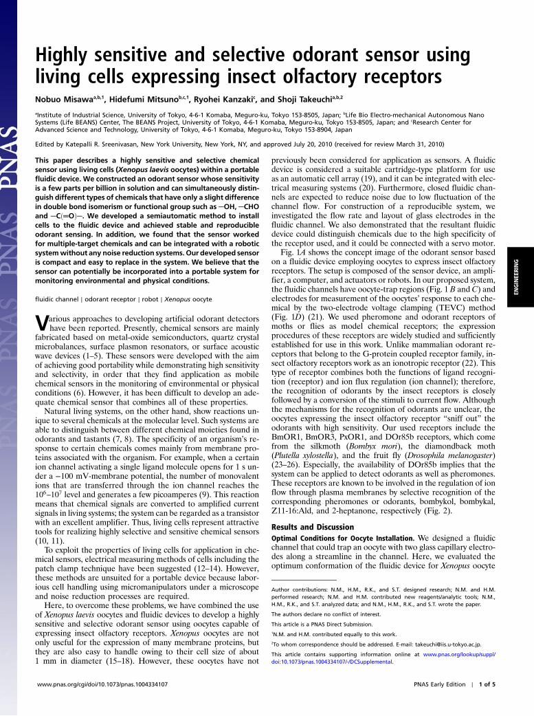
Fig. 1A shows the concept image of the odorant sensor basedon a fluidic device employing oocytes to express insect olfactoryreceptors. The setup is composed of the sensor device, an ampli-fier, a computer, and actuators or robots. In our proposed system,the fluidic channels have oocyte-trap regions (Fig. 1 B and C) andelectrodes for measurement of the oocytes’ response to each che-mical by the two-electrode voltage clamping (TEVC) method(Fig. 1D) (21). We used pheromone and odorant receptors ofmoths or flies as model chemical receptors; the expressionprocedures of these receptors are widely studied and sufficientlyestablished for use in this work. Unlike mammalian odorant re-ceptors that belong to the G-protein coupled receptor family, in-sect olfactory receptors work as an ionotropic receptor (22). Thistype of receptor combines both the functions of ligand recogni-tion (receptor) and ion flux regulation (ion channel); therefore,the recognition of odorants by the insect receptors is closelyfollowed by a conversion of the stimuli to current flow. Althoughthe mechanisms for the recognition of odorants are unclear, theoocytes expressing the insect olfactory receptor “sniff out” theodorants with high sensitivity. Our used receptors include theBmOR1, BmOR3, PxOR1, and DOr85b receptors, which comefrom the silkmoth (Bombyx mori), the diamondback moth(Plutella xylostella), and the fruit fly (Drosophila melanogaster)(23–26). Especially, the availability of DOr85b implies that thesystem can be applied to detect odorants as well as pheromones.These receptors are known to be involved in the regulation of ionflow through plasma membranes by selective recognition of thecorresponding pheromones or odorants, bombykol, bombykal,Z11-16:Ald, and 2-heptanone, respectively (Fig. 2).
Results and DiscussionOptimal Conditions for Oocyte Installation. We designed a fluidicchannel that could trap an oocyte with two glass capillary electro-des along a streamline in the channel. Here, we evaluated theoptimum conformation of the fluidic device for Xenopus oocyte
Author contributions: N.M., H.M., R.K., and S.T. designed research; N.M. and H.M.performed research; N.M. and H.M. contributed new reagents/analytic tools; N.M.,H.M., R.K., and S.T. analyzed data; and N.M., H.M., R.K., and S.T. wrote the paper.
The authors declare no conflict of interest.
This article is a PNAS Direct Submission.1N.M. and H.M. contributed equally to this work.2To whom correspondence should be addressed. E-mail: [email protected].
This article contains supporting information online at www.pnas.org/lookup/suppl/doi:10.1073/pnas.1004334107/-/DCSupplemental.
www.pnas.org/cgi/doi/10.1073/pnas.1004334107 PNAS Early Edition ∣ 1 of 5
ENGINEE
RING
trapping and electrophysiological measurements. The fluidic de-vice was made of acrylic material. Two glass capillary electrodeswere symmetrically placed in the device along the channel (Fig. 1B and C). In the case of multichannel detection, they wereinstalled in series as described in Materials and Methods.
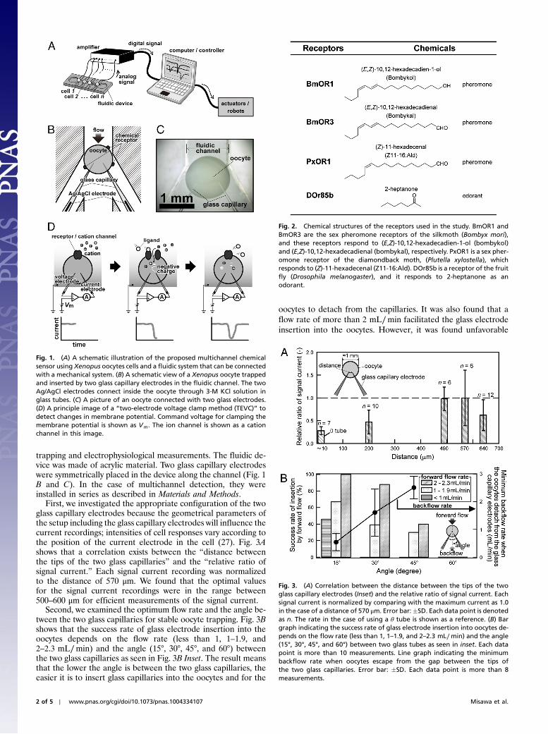
First, we investigated the appropriate configuration of the twoglass capillary electrodes because the geometrical parameters ofthe setup including the glass capillary electrodes will influence thecurrent recordings; intensities of cell responses vary according tothe position of the current electrode in the cell (27). Fig. 3Ashows that a correlation exists between the “distance betweenthe tips of the two glass capillaries” and the “relative ratio ofsignal current.” Each signal current recording was normalizedto the distance of 570 μm. We found that the optimal valuesfor the signal current recordings were in the range between500–600 μm for efficient measurements of the signal current.
Second, we examined the optimum flow rate and the angle be-tween the two glass capillaries for stable oocyte trapping. Fig. 3Bshows that the success rate of glass electrode insertion into theoocytes depends on the flow rate (less than 1, 1–1.9, and2–2.3 mL∕min) and the angle (15°, 30°, 45°, and 60°) betweenthe two glass capillaries as seen in Fig. 3B Inset. The result meansthat the lower the angle is between the two glass capillaries, theeasier it is to insert glass capillaries into the oocytes and for the
oocytes to detach from the capillaries. It was also found that aflow rate of more than 2 mL∕min facilitated the glass electrodeinsertion into the oocytes. However, it was found unfavorable
Fig. 1. (A) A schematic illustration of the proposed multichannel chemicalsensor using Xenopus oocytes cells and a fluidic system that can be connectedwith a mechanical system. (B) A schematic view of a Xenopus oocyte trappedand inserted by two glass capillary electrodes in the fluidic channel. The twoAg/AgCl electrodes connect inside the oocyte through 3-M KCl solution inglass tubes. (C) A picture of an oocyte connected with two glass electrodes.(D) A principle image of a “two-electrode voltage clamp method (TEVC)” todetect changes in membrane potential. Command voltage for clamping themembrane potential is shown as Vm. The ion channel is shown as a cationchannel in this image.
Fig. 2. Chemical structures of the receptors used in the study. BmOR1 andBmOR3 are the sex pheromone receptors of the silkmoth (Bombyx mori),and these receptors respond to (E,Z)-10,12-hexadecadien-1-ol (bombykol)and (E,Z)-10,12-hexadecadienal (bombykal), respectively. PxOR1 is a sex pher-omone receptor of the diamondback moth, (Plutella xylostella), whichresponds to (Z)-11-hexadecenal (Z11-16:Ald). DOr85b is a receptor of the fruitfly (Drosophila melanogaster), and it responds to 2-heptanone as anodorant.
Fig. 3. (A) Correlation between the distance between the tips of the twoglass capillary electrodes (Inset) and the relative ratio of signal current. Eachsignal current is normalized by comparing with the maximum current as 1.0in the case of a distance of 570 μm. Error bar:�SD. Each data point is denotedas n. The rate in the case of using a θ tube is shown as a reference. (B) Bargraph indicating the success rate of glass electrode insertion into oocytes de-pends on the flow rate (less than 1, 1–1.9, and 2–2.3 mL∕min) and the angle(15°, 30°, 45°, and 60°) between two glass tubes as seen in inset. Each datapoint is more than 10 measurements. Line graph indicating the minimumbackflow rate when oocytes escape from the gap between the tips ofthe two glass capillaries. Error bar: �SD. Each data point is more than 8measurements.
2 of 5 ∣ www.pnas.org/cgi/doi/10.1073/pnas.1004334107 Misawa et al.
that oocytes detached from the glass capillaries due to the back-flow that was generated occasionally from the pulsing motioncaused by pumping. And, the glass capillaries penetrated throughthe oocyte when the flow rate was too high (> about 2.3 mL∕min). As a result, the optimal values for the angle between thetwo glass capillaries and the flow rate for stable trapping of oo-cytes were determined to be 30° and ∼2 mL∕min, respectively.Under these conditions, it is evident that in our proposed system,conventional electrophysiological setups (e.g., micromanipula-tors and a microscope) are unnecessary. The semiautomatic mea-surements are thus accomplished due to the high reproducibilityof the oocyte installation system.
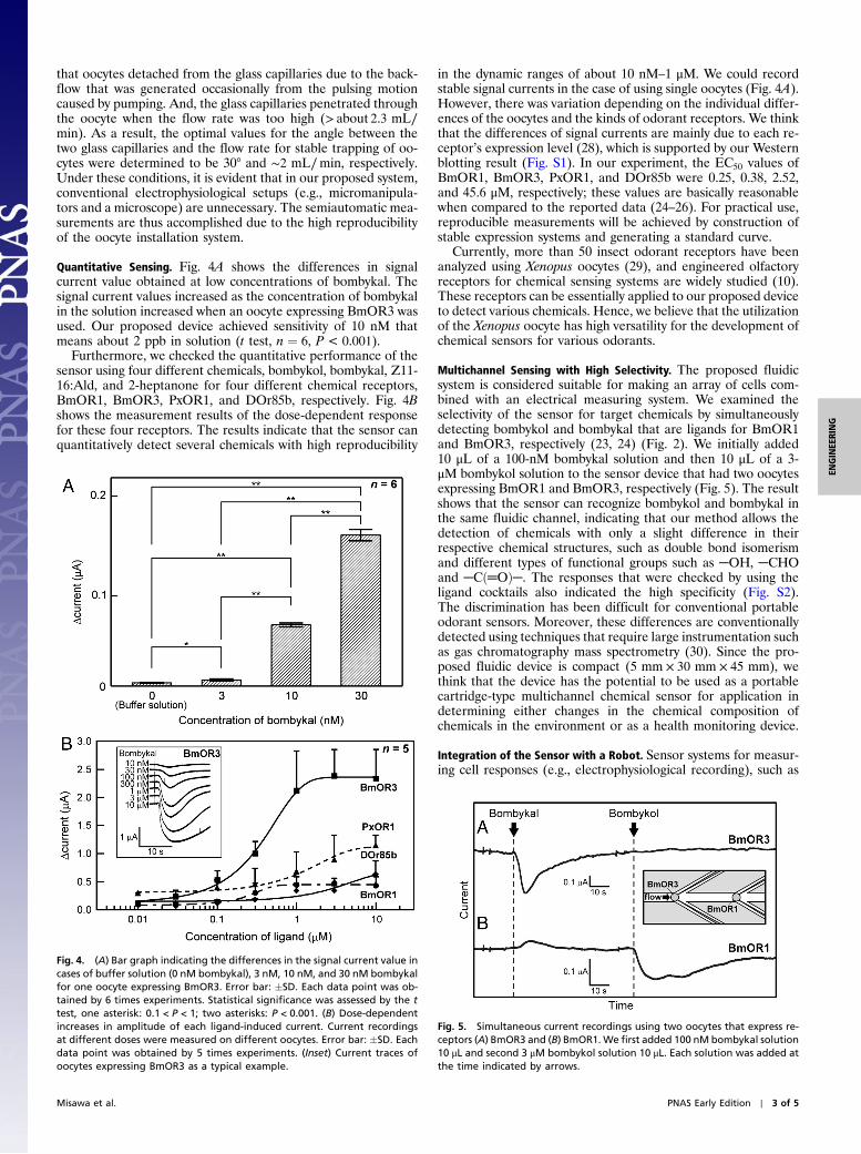
Quantitative Sensing. Fig. 4A shows the differences in signalcurrent value obtained at low concentrations of bombykal. Thesignal current values increased as the concentration of bombykalin the solution increased when an oocyte expressing BmOR3 wasused. Our proposed device achieved sensitivity of 10 nM thatmeans about 2 ppb in solution (t test, n ¼ 6, P < 0.001).
Furthermore, we checked the quantitative performance of thesensor using four different chemicals, bombykol, bombykal, Z11-16:Ald, and 2-heptanone for four different chemical receptors,BmOR1, BmOR3, PxOR1, and DOr85b, respectively. Fig. 4Bshows the measurement results of the dose-dependent responsefor these four receptors. The results indicate that the sensor canquantitatively detect several chemicals with high reproducibility
in the dynamic ranges of about 10 nM–1 μM. We could recordstable signal currents in the case of using single oocytes (Fig. 4A).However, there was variation depending on the individual differ-ences of the oocytes and the kinds of odorant receptors. We thinkthat the differences of signal currents are mainly due to each re-ceptor’s expression level (28), which is supported by our Westernblotting result (Fig. S1). In our experiment, the EC50 values ofBmOR1, BmOR3, PxOR1, and DOr85b were 0.25, 0.38, 2.52,and 45.6 μM, respectively; these values are basically reasonablewhen compared to the reported data (24–26). For practical use,reproducible measurements will be achieved by construction ofstable expression systems and generating a standard curve.
Currently, more than 50 insect odorant receptors have beenanalyzed using Xenopus oocytes (29), and engineered olfactoryreceptors for chemical sensing systems are widely studied (10).These receptors can be essentially applied to our proposed deviceto detect various chemicals. Hence, we believe that the utilizationof the Xenopus oocyte has high versatility for the development ofchemical sensors for various odorants.
Multichannel Sensing with High Selectivity. The proposed fluidicsystem is considered suitable for making an array of cells com-bined with an electrical measuring system. We examined theselectivity of the sensor for target chemicals by simultaneouslydetecting bombykol and bombykal that are ligands for BmOR1and BmOR3, respectively (23, 24) (Fig. 2). We initially added10 μL of a 100-nM bombykal solution and then 10 μL of a 3-μM bombykol solution to the sensor device that had two oocytesexpressing BmOR1 and BmOR3, respectively (Fig. 5). The resultshows that the sensor can recognize bombykol and bombykal inthe same fluidic channel, indicating that our method allows thedetection of chemicals with only a slight difference in theirrespective chemical structures, such as double bond isomerismand different types of functional groups such as ─OH, ─CHOand ─Cð═OÞ─. The responses that were checked by using theligand cocktails also indicated the high specificity (Fig. S2).The discrimination has been difficult for conventional portableodorant sensors. Moreover, these differences are conventionallydetected using techniques that require large instrumentation suchas gas chromatography mass spectrometry (30). Since the pro-posed fluidic device is compact (5 mm × 30 mm × 45 mm), wethink that the device has the potential to be used as a portablecartridge-type multichannel chemical sensor for application indetermining either changes in the chemical composition ofchemicals in the environment or as a health monitoring device.
Integration of the Sensor with a Robot. Sensor systems for measur-ing cell responses (e.g., electrophysiological recording), such as
Fig. 4. (A) Bar graph indicating the differences in the signal current value incases of buffer solution (0 nM bombykal), 3 nM, 10 nM, and 30 nM bombykalfor one oocyte expressing BmOR3. Error bar: �SD. Each data point was ob-tained by 6 times experiments. Statistical significance was assessed by the ttest, one asterisk: 0.1 < P < 1; two asterisks: P < 0.001. (B) Dose-dependentincreases in amplitude of each ligand-induced current. Current recordingsat different doses were measured on different oocytes. Error bar: �SD. Eachdata point was obtained by 5 times experiments. (Inset) Current traces ofoocytes expressing BmOR3 as a typical example.
Fig. 5. Simultaneous current recordings using two oocytes that express re-ceptors (A) BmOR3 and (B) BmOR1. We first added 100 nM bombykal solution10 μL and second 3 μM bombykol solution 10 μL. Each solution was added atthe time indicated by arrows.
Misawa et al. PNAS Early Edition ∣ 3 of 5
ENGINEE
RING

the patch clamp technique, typically employ a noise reduction sys-tem such as a Faraday cage to cancel out background noise and tomaximize the signal-to-noise ratio. This configuration is usuallyindispensable when the sensor is used under noisy conditions.We mounted the sensor device onto a robotic system withoutany noise reduction system. As shown in Fig. 6A, we installedthe sensor device into the head of a robot mannequin and con-nected it to an electric motor via an amplifier. The sensor devicewas configured with an oocyte expressing PxOR1, whereas theelectric motor was configured such that when the sensor devicedetected a threshold value of Z11-16:Ald, this triggered actuationof the electric motor causing the robot’s head to move back andforth (i.e., shake) twice.
We initially added 100 μL of buffer solution as a negative con-trol and subsequently added 100 μL of a 10 μM Z11-16:Ald solu-tion to the sensor. The system successfully showed a hightolerance to noise, even during shaking (i.e., back-and-forthmotion) of the robot’s head (Movie S1). We evaluated the noiselevel determined by standard deviation of the peak values in thenoise. As a result, the noise induced by the head shaking of therobot was �150 nA (SD) and the background noise was �10 nA(SD). On the other hand, the background noise was significantlyhigh [�260 nA (SD)] when we used a conventional open cham-ber that was positioned outside of the Faraday cage. We attributethe noise tolerance to (i) the closed and small fluidic system and(ii) the oocyte that is firmly impaled by the glass capillaries, whichrestrains its movement during the shaking. This demonstrationimplies that the sensor can be directly mounted on a movingrobot programmed to react chemicals in the environment.
ConclusionsWe have constructed a highly sensitive and selective odorantsensor using Xenopus oocytes expressing insect olfactory recep-tors. It was found that this sensor could detect different typesof chemicals that have only a slight difference in chemical com-position with sensitivity of a few parts per billion in solution.Moreover, we found that the sensor worked for multiple-targetchemicals and can be integrated with a robotic system withoutnoise reduction systems. Hence, this biohybrid sensor deviceprovides an innovative platform to equip robots with odorant sen-sors. We believe that the sensor can potentially be incorporatedinto a machine that can be useful for several applications, includ-ing food administration, environmental monitoring, and healthmanagement.
Materials and MethodsDevice Fabrication and Oocyte Trapping. The device was composed of fabri-cated acrylic material, glass capillaries (B100F-3, World Precision Instruments,Inc.), and Ag/AgCl electrodes (0.4 mm in diameter AG-401355, The Nilaco Co.)made in advance by dipping in a commercial bleach agent overnight.
The fluidic device was fabricated by machining a 5-mm-thick acrylic plate(Mitsubishi rayon, Acrylite L) with an automated computer-aided-design/computer-aided-manufacturing modeling machine (Modia systems, MM-100) with a 1-mm diameter drill.
The glass capillary electrodes were fabricated from glass capillaries withfilaments, with an outer diameter of 1.0 mm and an inner diameter of0.75 mm (TW100F-3; World Precision Instruments, Inc.). The capillary waspulled using a P-2000 laser puller (Sutter Instrument Co.) preprogrammedto fabricate pipettes with an inner diameter of less than 50 μm. Parametersused were Heat: 260, Fil: 4, Vel: 100, Del: 150, and Pul: 90. The tips of theresulting capillaries had inner diameters of less than ∼50 μm.
The Ag/AgCl electrodes were inserted into the glass capillaries for themeasurements of the oocyte responses. The capillaries were initially filledwith a 3-M KCl solution.
The fluidic channel was filled with Barth’s solution (88 mM NaCl, 1 mMKCl, 0.3 mM CaðNO3Þ2, 0.4 mM CaCl2, 0.8 mM MgSO4, 2.4 mM NaHCO3,15 mM Hepes, pH 7.6). The solution was perfused constantly using a peristal-tic pump. The solution flows in the channel at a flow rate of 1–2 mL∕min.
For the installation of an oocyte, the oocyte is first introduced and flowedinto the fluidic channel, and it can be then trapped by insertion of two glasscapillary electrodes embedded in the fluidic channel. In the case of multi-channel measurements, we installed the multiple oocytes to the trappingarea one by one before sealing with the lid of the fluidic channel; they werethen captured after sealing with the lid (Fig. 5 Inset).
The trapped oocytes are exposed to the solution containing chemicalssolubilized by 1% DMSO. Even though a difference in protein expressionhas been reported between the vegetal pole and the animal pole of theoocytes (15, 31), the point of insertion of the electrodes into the oocytesis not considered to cause a significant difference in measurements usingthe TEVC method. Therefore, we did not control the orientation of theoocytes in our proposed system.
Receptor Expression in Xenopus laevis Oocyte and Electrophysiological Record-ing. Stage V to VI oocytes were treated with 1.5 mg∕mL collagenase (WakoPure Chemical Industries, Ltd.) in Ca2þ-free saline solution (82.5 mM NaCl,2 mM KCl, 1 mM MgCl2, 5 mM Hepes, pH7.5) for 1.5 h at 20 °C. The oocyteswere then microinjected with 25 ng each of the odorant receptor gene(BmOR1 or BmOR3 or PxOR1 or DOr85b) RNA and coreceptor protein gene(Or83b family gene) RNA synthesized by mMESSAGE mMACHINE (AmbionInc.). The injected oocytes were incubated for a few days at 20 °C in Barth’ssolution supplemented with 10 μg∕mL penicillin and streptomycin. We usedoocytes that were nearly the same size as each other [1.3� 0.1 mm (SD),(n > 100)] and showed no significant differences in their responses. The signalcurrents of the oocytes were recorded with a two-electrode voltage clampingmethod using a custom-built multichannel amplifier (Triton, Tecella, LLC). Thecurrents were monitored every 100 μs at a hold voltage of −80 mV. In the
Fig. 6. (A) Images of an odorant sensor using a Xenopus oocyte trapped and inserted between two electrodes in a fluidic device connected to the electricmotor of a head-shaking robotic system outside of a Faraday cage. The head of a robot mannequin was made of styrofoam. (B) Sequential images and thecurrent trace of the robot’s head shaking, which was triggered by an olfactory stimulus using Z11-16:Ald recognized by PxOR1. Each number in the sequentialimage corresponds to the equivalent number on the current trace. The threshold level is represented as a dashed line.
4 of 5 ∣ www.pnas.org/cgi/doi/10.1073/pnas.1004334107 Misawa et al.
case of using oocytes expressing BmOR3, the response remained viable in thedevice for about 12 h at room temperature (Fig. S3).
Chemicals were prepared in Barth’s solution including 1% DMSO. Concen-trated stock solutions (20 μL) of each of the chemicals were added to the re-cording bath to provide the indicated final concentrations. Additionally, wethink that systems for the solubilization of ligands into the device will helpour system. Although ligands are dissolved by DMSO in this study, gaspermeable materials and usages of odorant-binding proteins will be usefulfor incorporation of volatile chemicals into the fluidic device (32).
Robot Integration. The sensor device was set inside the head of a robot man-nequinmade of styrofoam, and ligand solutions were injected into the fluidicchannel connected with a plastic tube passing through the head of the robot.
The Ag/AgCl electrodes were connected to an electric motor through theamplifier and a programmed microcomputer (Coron, Techno-road Co.). The
electric motor was controlled by the microcomputer to move back and forthtwo times when the signal was over the threshold. We simultaneouslymonitored the shaking of the robot head and the current tracing usingthe computer attached to the amplifier.
ACKNOWLEDGMENTS. The authors thank Prof. I. Shimoyama and his col-leagues at Information and Robot Technology Research Initiative of theUniversity of Tokyo for helpful discussions, and Prof. M. Asashima of the Uni-versity of Tokyo for kindly providing the Xenopus laevis oocytes. We also ap-preciate the generous support by Y. Tanaka of Tecella, LLC for customizationof the multichannel amplifier and the substantial contribution by H. Ishihara,S. Takaya, and S. Sugimoto of the University of Tokyo for the robot integra-tion. This work was partly supported by the New Energy and IndustrialTechnology Development Organization and by Tokyo Electron Ltd.
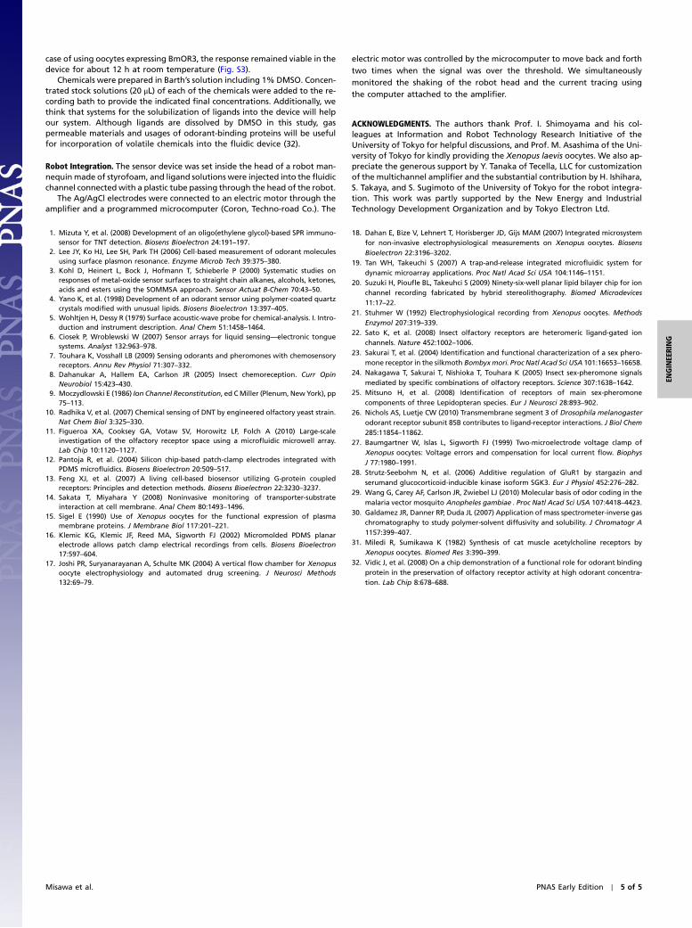
1. Mizuta Y, et al. (2008) Development of an oligo(ethylene glycol)-based SPR immuno-sensor for TNT detection. Biosens Bioelectron 24:191–197.
2. Lee JY, Ko HJ, Lee SH, Park TH (2006) Cell-based measurement of odorant moleculesusing surface plasmon resonance. Enzyme Microb Tech 39:375–380.
3. Kohl D, Heinert L, Bock J, Hofmann T, Schieberle P (2000) Systematic studies onresponses of metal-oxide sensor surfaces to straight chain alkanes, alcohols, ketones,acids and esters using the SOMMSA approach. Sensor Actuat B-Chem 70:43–50.
4. Yano K, et al. (1998) Development of an odorant sensor using polymer-coated quartzcrystals modified with unusual lipids. Biosens Bioelectron 13:397–405.
5. Wohltjen H, Dessy R (1979) Surface acoustic-wave probe for chemical-analysis. I. Intro-duction and instrument description. Anal Chem 51:1458–1464.
6. Ciosek P, Wroblewski W (2007) Sensor arrays for liquid sensing—electronic tonguesystems. Analyst 132:963–978.
7. Touhara K, Vosshall LB (2009) Sensing odorants and pheromones with chemosensoryreceptors. Annu Rev Physiol 71:307–332.
8. Dahanukar A, Hallem EA, Carlson JR (2005) Insect chemoreception. Curr OpinNeurobiol 15:423–430.
9. Moczydlowski E (1986) Ion Channel Reconstitution, ed CMiller (Plenum, NewYork), pp75–113.
10. Radhika V, et al. (2007) Chemical sensing of DNT by engineered olfactory yeast strain.Nat Chem Biol 3:325–330.
11. Figueroa XA, Cooksey GA, Votaw SV, Horowitz LF, Folch A (2010) Large-scaleinvestigation of the olfactory receptor space using a microfluidic microwell array.Lab Chip 10:1120–1127.
12. Pantoja R, et al. (2004) Silicon chip-based patch-clamp electrodes integrated withPDMS microfluidics. Biosens Bioelectron 20:509–517.
13. Feng XJ, et al. (2007) A living cell-based biosensor utilizing G-protein coupledreceptors: Principles and detection methods. Biosens Bioelectron 22:3230–3237.
14. Sakata T, Miyahara Y (2008) Noninvasive monitoring of transporter-substrateinteraction at cell membrane. Anal Chem 80:1493–1496.
15. Sigel E (1990) Use of Xenopus oocytes for the functional expression of plasmamembrane proteins. J Membrane Biol 117:201–221.
16. Klemic KG, Klemic JF, Reed MA, Sigworth FJ (2002) Micromolded PDMS planarelectrode allows patch clamp electrical recordings from cells. Biosens Bioelectron17:597–604.
17. Joshi PR, Suryanarayanan A, Schulte MK (2004) A vertical flow chamber for Xenopusoocyte electrophysiology and automated drug screening. J Neurosci Methods132:69–79.
18. Dahan E, Bize V, Lehnert T, Horisberger JD, Gijs MAM (2007) Integrated microsystemfor non-invasive electrophysiological measurements on Xenopus oocytes. BiosensBioelectron 22:3196–3202.
19. Tan WH, Takeuchi S (2007) A trap-and-release integrated microfluidic system fordynamic microarray applications. Proc Natl Acad Sci USA 104:1146–1151.
20. Suzuki H, Pioufle BL, Takeuhci S (2009) Ninety-six-well planar lipid bilayer chip for ionchannel recording fabricated by hybrid stereolithography. Biomed Microdevices11:17–22.
21. Stuhmer W (1992) Electrophysiological recording from Xenopus oocytes. MethodsEnzymol 207:319–339.
22. Sato K, et al. (2008) Insect olfactory receptors are heteromeric ligand-gated ionchannels. Nature 452:1002–1006.
23. Sakurai T, et al. (2004) Identification and functional characterization of a sex phero-mone receptor in the silkmoth Bombyxmori. Proc Natl Acad Sci USA 101:16653–16658.
24. Nakagawa T, Sakurai T, Nishioka T, Touhara K (2005) Insect sex-pheromone signalsmediated by specific combinations of olfactory receptors. Science 307:1638–1642.
25. Mitsuno H, et al. (2008) Identification of receptors of main sex-pheromonecomponents of three Lepidopteran species. Eur J Neurosci 28:893–902.
26. Nichols AS, Luetje CW (2010) Transmembrane segment 3 of Drosophila melanogasterodorant receptor subunit 85B contributes to ligand-receptor interactions. J Biol Chem285:11854–11862.
27. Baumgartner W, Islas L, Sigworth FJ (1999) Two-microelectrode voltage clamp ofXenopus oocytes: Voltage errors and compensation for local current flow. BiophysJ 77:1980–1991.
28. Strutz-Seebohm N, et al. (2006) Additive regulation of GluR1 by stargazin andserumand glucocorticoid-inducible kinase isoform SGK3. Eur J Physiol 452:276–282.
29. Wang G, Carey AF, Carlson JR, Zwiebel LJ (2010) Molecular basis of odor coding in themalaria vector mosquito Anopheles gambiae . Proc Natl Acad Sci USA 107:4418–4423.
30. Galdamez JR, Danner RP, Duda JL (2007) Application of mass spectrometer-inverse gaschromatography to study polymer-solvent diffusivity and solubility. J Chromatogr A1157:399–407.
31. Miledi R, Sumikawa K (1982) Synthesis of cat muscle acetylcholine receptors byXenopus oocytes. Biomed Res 3:390–399.
32. Vidic J, et al. (2008) On a chip demonstration of a functional role for odorant bindingprotein in the preservation of olfactory receptor activity at high odorant concentra-tion. Lab Chip 8:678–688.
Misawa et al. PNAS Early Edition ∣ 5 of 5
ENGINEE
RING