Embed Size (px)
Citation preview

HIMOINSA empresa con certificación de calidad ISO 9001
Los grupos electrógenos HIMOINSA cumplen el marcado CE que incluye las siguientes directivas:
• EN ISO 13857:2008 Seguridad de Máquinas.
• 2006/95/CE de Baja Tensión.
• 89/336/CEE de Compatibilidad Electromagnética.
• 2000/14/CE Emisiones Sonoras de Máquinas de uso al aire libre.
(modificada por 2005/88/CE)
• 97/68/CE de Emisión de Gases y Partículas contaminantes.
(modificada por 2002/88/CE y 2004/26/CE)
HIMOINSA Company with quality certification ISO 9001
HIMOINSA gensets are compliant with EC mark which includes the following directives:• EN ISO 13857:2008 Machinery safety.
• 2006/95/EC Low voltage.
• 89/336/EEC Electromagnetic compatibility.
• 2000/14/EC Sound Power level. Noise emissions outdoor equipment.
(amended by 2005/88/EC)
• 97/68/EC Emissions of gaseous and particulate pollutants.
(amended by 2002/88/EC & 2004/26/EC)
Ambient conditions of reference: 1000 mbar, 25ºC, 30% relative humidity. Power according to ISO 3046 normative.
P.R.P. Prime Power - ISO 8528 : prime power is the maximum power available during a variable power sequence, which may be run for an unlimited number of hours per year, between stated maintenance intervals. The permissible average power output during a 24 hours period shall not exceed 80% of the prime power. 10% overload available for governing purposes only.
Standby Power (ISO 3046 Fuel Stop power): power available for use at variable loads for limited annual time (500h), within the following limits of maximum operating time: 100% load 25h per year – 90% load 200h per year. No overload available. Applicable in case of failure of the main in areas of reliable electrical network.
Himoinsa reserves the right to modify any characteristic prior notifice. The illustrations may include optional equipment and/or accessories. Not contractual images. The technical indications described in this brochure correspond to the information available at the moment of printing. ©HIMOINSA
Condiciones ambientales de referencia: 1000 mbar, 25ºC, 30% humedad relativa. Potencia según la norma ISO 3046.
P.R.P. - ISO 8528: es la potencia máxima disponible para un ciclo de potencia variable que puede ocurrir por un número ilimitado de horas por año, entre los periodos de mantenimiento señalados. La potencia media consumible durante un periodo de 24 horas no debe rebasar del 80% de la P.R.P. 10 % de sobrecarga es permitido solo para efectos de regulación.
Stand-byPower (ISO 3046 Fuel Stop power) - Es la potencia máxima disponible para empleo bajo cargas variables por número limitado de horas por año (500h) dentro de los siguientes límites máximos de funcionamiento: 100% de la carga 25h/año - 90% de la carga 200h/año. No existe sobrecarga. Es aplicable en caso de interrupción de la distribución en zonas de red eléctrica fiable.
Himoinsa se reserva el derecho de modificar cualquier característica sin previa notificación. Las ilustraciones pueden incluir equipamiento opcional y/o accesorios. Imágenes no contractuales. Las indicaciones técnicas descritas en este
catálogo se corresponden con la información disponible en el momento de la impresión. ©HIMOINSA
ASIA - PACÍFICO / PACIFIC - ASIA
HIMOINSA CHINA CO. LTDTLF. +86 519 86 22 66 88 FAX: +86 519 86 22 66 87
HIMOINSA FAR EAST PTE LTDTLF. +65 6 265 10 11 FAX: +65 6 265 11 41
HIMOINSA CENTRAL ASIA (KAZAKHSTAN)TLF/FAX: +7 727 392 3688
ORIENTE MEDIO / MIDDLE EAST
HIMOINSA MIDDLE EAST FZETLF. +971 4 887 33 15 FAX: +971 4 887 33 18
AMERICA
HIMOINSA MEXICOTLF. +52 (33) 3675 86 46 FAX: +52 (33) 3914 25 90
HIMOINSA POWER SYSTEMS, INC. (USA)TLF. +1 913 495 55 57 FAX: +1 913 495 55 75
HIMOINSA PTY (PANAMA)TLF. +507 232 57 41 FAX: +507 232 64 59
HIMOINSA LATINOAMERICA (Rep. Argentina)TLF. +54 2320 40 1900 / 1901
EUROPA / EUROPE
GENELEC S.A.S. (HIMOINSA FRANCE)TLF. +33 474 62 65 05 FAX: +33 474 09 07 28
HIMOINSA ITALIA S.R.L.TLF. +39 0444 58 09 22 FAX: +39 0444 183 33 08
HIMOINSA PORTUGAL LDATLF. +351 21 426 65 50 FAX: +351 21 426 65 69
HIMOINSA POLSKA SP. Z O. O.TLF. +48 22 868 19 18 FAX: +48 22 868 19 31
HIMOINSA DEUTSCHLANDTLF. +49 9372 9495447 FAX: +49 6009 62108
HIMOINSA CENTRO (Madrid)
TLF. +34 91 684 21 06 FAX +34 91 684 21 07
Centro de Distribución RecambiosSpare Parts Distribution Centre
TLF. +34 968 33 40 15 FAX +34 968 19 11 53
HIMOINSA CENTRAL_HEAD OFFICE
HIMOINSA S.L
Ctra. Murcia - San Javier, km 23.6
30730 San Javier (MURCIA) SPAIN
TLF. +34 968 19 11 28 / +34 902 19 11 28�FAX +34 968 19 12 17
EXPORT FAX +34 968 19 04 20 /+34 968 33 43 03
[email protected]_www.himoinsa.com
FILIALES_SUBSIDIARIES
Gama de ProductoProduct Range

i ÍNDICE_INDEX
PG. 41
PG. 43
PG. 37
PG. 25
PG. 29
PG. 21
HLA
HZA
AIREAIR
AGUAWATER
HDW
HYW
HFW
HSW
HVWPG. 33
PG. 48
PG. 49HR
PG. 54
PG. 55
GAMA POWERPACKPOWERPACK RANGE
POWERPACK
GAMA PORTATILPORTABLE RANGE
HGRGPG. 63
HGYGPG. 69
PG. 78
PG. 79
TORRES DE ILUMINACIÓNLIGHTING TOWERS
APOLO COMPACT
PG. 83
PG. 87
HZA
HLAPG. 71
PG. 73
HLA PG. 76
PRESENTACION_PRESENTATION
EMPRESACOMPANY
SERVICIO TÉCNICOTECHNICAL SERVICE
PG. 1
PG. 2
PG. 5
PG. 7HTW
HMWPG. 11
ALCANCE DE SUMINISTROSCOPE OF SUPPLY
ALCANCE DE SUMINISTROSCOPE OF SUPPLY
PG. 17
INGENIERÍA Y CENTRO DE FORMACIÓNENGINEERING & TRAINING CENTER
PG. 3
GRUPOS ELECTRÓGENOSGENERATING SETS
S
GAMA PESADAHEAVY RANGE
PG. 4
S
PG. 16GAMA PROFESIONALPROFESSIONAL RANGE
GAMA HRHR_RANGE
PG. 60GAMA POWERPLANTPOWERPLANT RANGE
PG. 62
APOLO 2000
APOLO 8000
CUADROS DE CONTROL Y POTENCIA_GAMA PROFESIONAL
CONTROL & POWER PANELS_PROFESSIONAL RANGE
OP OPCIONALES_GAMA PROFESIONAL Y HR
OPTIONALS_PROFESSIONAL RANGE & HR
PG. 90
PG. 100
HZA CUADROS DE CONTROL_CONTROL PANELS PG. 77
DETALLES Y DATOS TÉCNICOSTECHNICAL DATA & FEATURES
DETALLES Y DATOS TÉCNICOSTECHNICAL DATA & FEATURES
DETALLES Y DATOS TÉCNICOSTECHNICAL DATA & FEATURES
DETALLES Y DATOS TÉCNICOSTECHNICAL DATA & FEATURES
DETALLES Y DATOS TÉCNICOSTECHNICAL DATA & FEATURES
DETALLES Y DATOS TÉCNICOSTECHNICAL DATA & FEATURES
DETALLES Y DATOS TÉCNICOSTECHNICAL DATA & FEATURES
DETALLES Y DATOS TÉCNICOSTECHNICAL DATA & FEATURES
DETALLES Y DATOS TÉCNICOSTECHNICAL DATA & FEATURES
ALCANCE DE SUMINISTRO Y DATOSSCOPE OF SUPPLY & DATA
ALCANCE DE SUMINISTRO Y DATOSSCOPE OF SUPPLY & DATA
ALCANCE DE SUMINISTRO Y DATOSSCOPE OF SUPPLY & DATA
ALCANCE DE SUMINISTRO, DATOS Y CUADROS DE CONTROL
SCOPE OF SUPPLY, DATA & CONTROL PANELS
ALCANCE DE SUMINISTRO, DATOS Y CUADROS DE CONTROL
SCOPE OF SUPPLY, DATA & CONTROL PANELS
ALCANCE DE SUMINISTRO Y DATOSSCOPE OF SUPPLY & DATA
CUADROS DE CONTROL_CONTROL PANELS
ALCANCE DE SUMINISTRO Y DATOSSCOPE OF SUPPLY & DATA
ALCANCE DE SUMINISTRO Y DATOSSCOPE OF SUPPLY & DATA
ALCANCE DE SUMINISTRO Y DATOSSCOPE OF SUPPLY & DATA
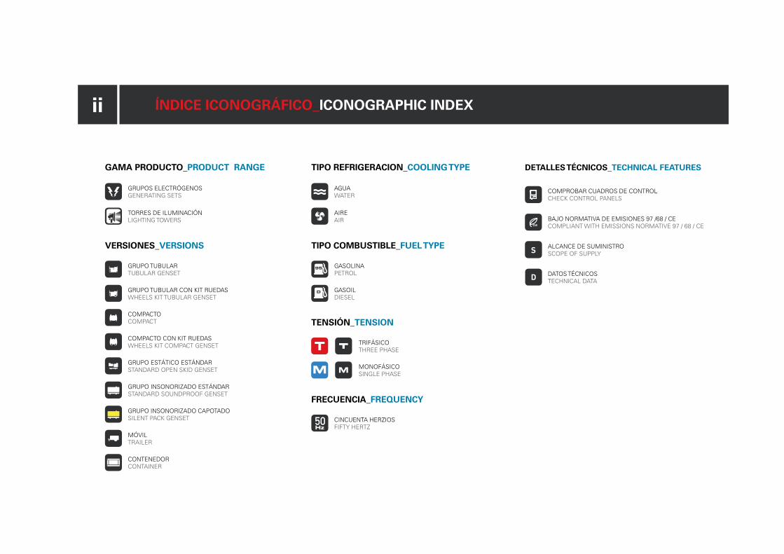
ii ÍNDICE ICONOGRÁFICO_ICONOGRAPHIC INDEX
TIPO REFRIGERACION_COOLING TYPE
AIREAIR
TIPO COMBUSTIBLE_FUEL TYPE
GASOLINAPETROL
GASOILDIESEL
TENSIÓN_TENSION
TRIFÁSICOTHREE PHASE
MONOFÁSICOSINGLE PHASE
AGUAWATER
FRECUENCIA_FREQUENCY
CINCUENTA HERZIOSFIFTY HERTZ
GAMA PRODUCTO_PRODUCT RANGE
GRUPOS ELECTRÓGENOSGENERATING SETS
TORRES DE ILUMINACIÓNLIGHTING TOWERS
VERSIONES_VERSIONS
GRUPO TUBULAR TUBULAR GENSET
GRUPO TUBULAR CON KIT RUEDASWHEELS KIT TUBULAR GENSET
COMPACTOCOMPACT
COMPACTO CON KIT RUEDASWHEELS KIT COMPACT GENSET
GRUPO ESTÁTICO ESTÁNDAR STANDARD OPEN SKID GENSET
GRUPO INSONORIZADO ESTÁNDARSTANDARD SOUNDPROOF GENSET
MÓVILTRAILER
GRUPO INSONORIZADO CAPOTADOSILENT PACK GENSET
CONTENEDORCONTAINER
DETALLES TÉCNICOS_TECHNICAL FEATURES
COMPROBAR CUADROS DE CONTROL CHECK CONTROL PANELS
BAJO NORMATIVA DE EMISIONES 97 /68 / CECOMPLIANT WITH EMISSIONS NORMATIVE 97 / 68 / CE
S ALCANCE DE SUMINISTRO SCOPE OF SUPPLY
D DATOS TÉCNICOS TECHNICAL DATA

1
Fundada en 1982, HIMOINSA, ubicada en
San Javier, Murcia, es una multinacional
focalizada en la fabricación y comercia-
lización de sistemas de generación de
energía capaces de satisfacer cualquiera
de las necesidades de aquellos que preci-
san de un suministro energético conti-
nuo, limpio, eficiente y garantizado.
TECNOLOGÍATecnología e investigación al servicio
de nuevos productos
Desde el principio, nuestro compromiso ha
sido la mejora continua en nuestros productos.
Estar a la vanguardia del mercado exige el uso
de últimas tecnologías; software de última
generación de diseño y cálculos estructura-
les, robótica especializada y un sistema de
producción totalmente automatizado que nos
permiten culminar con la fabricación en serie
de cualquier nueva línea de productos cum-
pliendo siempre con los estrictos estándares
de calidad de las normas ISO.
Founded in 1982, HIMOINSA, located
in San Javier, Murcia, is a multinational
focused on the manufacture and sales of
energy generation systems capable of sa-
tisfying any needs that require continous,
clean, efficient and guaranteed energy
supply.
TECHNOLOGYTechnology and investigation
for new products
From the beginning, our commitment has
been the continous improvement of our pro-
ducts. To be on the cutting-edge of the market
demands the use of the latest technoligies;
design software and structural calculations,
specialized robotics and totally automated
production system that culminates in the serial
manufacture of any new line of products wich
always complies with the strict requirements
of the ISO quality standards.

2
Servicio eficaz,respuesta inmediata
Effective service,
immediate response
Los altos niveles de productividad se
pueden mantener durante la vida útil
del equipo, siempre que realicemos
un mantenimiento preventivo ade-
cuado.
Nuestro Servicio Postventa se ajusta a sus necesidades y le garantiza la protección de su inversión con un servicio excelente a través de su amplia red de filiales , distribuido-res y servicios técnicos autorizados repartidos estratégicamente por toda la geografía mundial.
Una amplia red capaz de reaccionar de forma
rápida y eficiente ante cualquier necesidad del
cliente.
Contamos con un ágil departamento de Re-
cambios que permite la entrega de compo-
nentes en el plazo máximo de 24H en todo el
territorio europeo. En el ámbito internacional
disponemos además de nuestra propia red
de servicio y del apoyo de la red mundial de
nuestros prestigiosos proveedores.
The high levels of productivity can
be maintained during the life cycle of
the equipment, whenever we carry
out the necessary preventive mainte-
nance.
Our Post-Sales Service adjusts to your needs and guarantees the protection of your investment with excellent service via an extensive network of affiliates, distributors and authorized technical services distri-buted strategically throughout the world.
An extensive network that is capable of reac-
ting quickly and efficiently to any client’s need.
We have an agile Spare Parts department that
delivers components in a maximum period
of 24 H throughout Europe. In addition to our
own service network, internationally we have
the support of the global network of our presti-
gious suppliers.
Servicio Técnico_Technical service
3
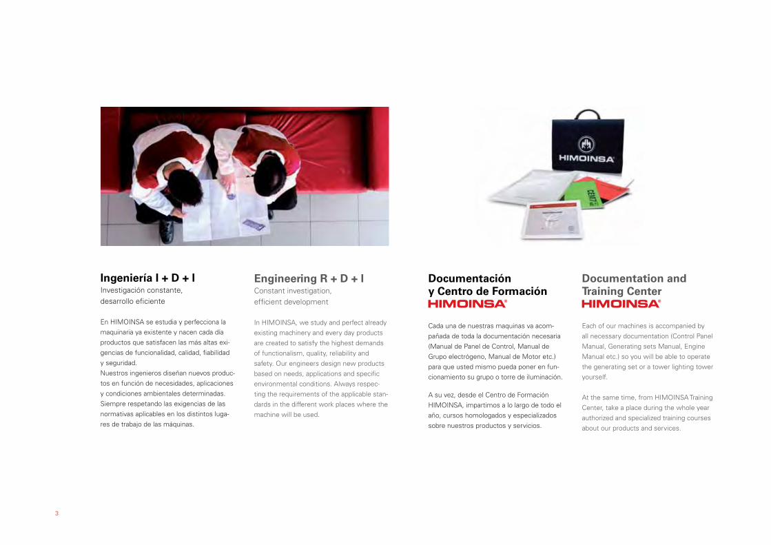
Ingeniería I + D + IInvestigación constante,
desarrollo eficiente
En HIMOINSA se estudia y perfecciona la
maquinaria ya existente y nacen cada día
productos que satisfacen las más altas exi-
gencias de funcionalidad, calidad, fiabilidad
y seguridad.
Nuestros ingenieros diseñan nuevos produc-
tos en función de necesidades, aplicaciones
y condiciones ambientales determinadas.
Siempre respetando las exigencias de las
normativas aplicables en los distintos luga-
res de trabajo de las máquinas.
Engineering R + D + IConstant investigation,
efficient development
In HIMOINSA, we study and perfect already
existing machinery and every day products
are created to satisfy the highest demands
of functionalism, quality, reliability and
safety. Our engineers design new products
based on needs, applications and specific
environmental conditions. Always respec-
ting the requirements of the applicable stan-
dards in the different work places where the
machine will be used.
Documentación y Centro de Formación
Cada una de nuestras maquinas va acom-
pañada de toda la documentación necesaria
(Manual de Panel de Control, Manual de
Grupo electrógeno, Manual de Motor etc.)
para que usted mismo pueda poner en fun-
cionamiento su grupo o torre de iluminación.
A su vez, desde el Centro de Formación
HIMOINSA, impartimos a lo largo de todo el
año, cursos homologados y especializados
sobre nuestros productos y servicios.
Documentation and Training Center
Each of our machines is accompanied by
all necessary documentation (Control Panel
Manual, Generating sets Manual, Engine
Manual etc.) so you will be able to operate
the generating set or a tower lighting tower
yourself.
At the same time, from HIMOINSA Training
Center, take a place during the whole year
authorized and specialized training courses
about our products and services.

APLICACIONES_APPLICATIONS:
Obras Públicas_Public Building Sites
Industrias_Industries
Construcción_Construction
Aeropuertos_Airports
Hospitales_Hospitals
Comunicaciones_Communications
4
GAMA PESADA | HEAVY RANGE
HTWHMW
SERIES: Powered by: MITSUBISHI
Powered by: MTU

5
MOTOR_ENGINE HTW HMW
Motor diesel, 4 tiempos, refrigerado por AGUA, turbo intercooler_Diesel engine, 4 cycle, WATER cooled, Turbo charged after cooler. �� √
Arranque eléctrico 24V_Electric start 24V � �
Radiador con ventilador aire forzado_Radiator with pusher fan � �
Filtro de aire estándar_Medium duty air ailter filter. � �
Filtro de combustible estándar_Standard fuel filter. � �
Filtro de aceite estándar_Standard oil filter. � �
Regulador electrónico_Electronic engine governor. � •
Gestión electrónica. (ADEC)_ADEC governor. • �
Sensor de alta Temperatura de refrigerante y Baja Presión de Aceite_HWT/LOP senders. � �
Sensor temperatura del aceite_Oil temperature senders. � �
Protecciones de partes calientes y móviles_Hot & rotating components (exhaust, fan,...) protections and radiator guards. � �
Bomba de extracción de aceite (manual)_Oil drain pump. (manual) � �
Sensor de bajo nivel de refrigerante_Low coolant level sensor. � �
Compensador de gases de escape_Exhaust gas compensator. � �
ALTERNADOR_ALTERNATOR
Alternador, autoexcitado y autorregulado_Self excited, self regulated alternator � �
Protección IP23, Aislamiento clase H_IP23 protection, Isolation class H � �
CONTROL Y POTENCIA_CONTROL AND POWER PANEL
Cuadro eléctrico de control y potencia, magnetotérmico para protección de sobrecarga_Control and power electric panel, main line circuit breaker for overload protection.
� �
Cuadro de conexión cableado con la protección de la seguridad. (protección magnetotérmica abierta y alarma)_Main bus / Hardwire connection panel with safety protection. (open thermal magnetic protection and alarm)
� �
SISTEMA ELÉCTRICO_ELECTRIC EQUIPMENT
Resistencia de caldeo. (versión automática)_ Water jacket heater. (automatic version) � �
Alternador de carga de baterías_ Battery charging alternator. � �
Batería gran poder de arranque instalada y conectada al motor, incluye/n cables y conectores_ Heavy - duty starting battery(s) installed and connected to the engine include cables and rack.
� �
Batería libre de mantenimiento y antiexplosión_ Free maintenance battery and explosion proof. �� √
Desconectador de batería_ Battery isolator. � �
Toma de tierra preparada para pica. (no suministrada)_ Ground connection prepared for ground spike. (not supplied) � �
S ALCANCE DE SUMINISTRO | SCOPE OF SUPPLY · GAMA PESADA_HEAVY RANGE
+ *

* Monoblock conformado por motor y alternador, ensamblado sobre chasis de acero mediante amortiguadores antivibratorios. (ESTÁNDAR EN TODOS LOS GRUPOS ELECTRÓGENOS)* Monoblock made of engine and Alternator, assembled on steel Chassis by means of rubber anti-vibrations shock absorbers. (STANDARD IN ALL GENERATING SETS)
6
CONTENEDOR INSONORIZADO Y CHASIS_SOUNDPROOFED CONTAINER & CHASSIS HTW HMW
Insonorización en contenedores de 20’ - 40’ ISO_Sound attenuated 20’ - 40’ ISO Container. � �
Capacidad del tanque de combustible: 20’ container: 1.300 Lts (1) - 1.350 Lts (2) - 1.400 (3)_20’ container: 1.300 Lts (1) - 1.350 Lts (2) - 1.400 (3) �� •
Capacidad del tanque de combustible_ Fuel tank capacity: 40’ container: 2.000 Lts. �� •
Construcción robusta diseñada para aplicaciones en continuo o emergencia_ Heavy - duty construction designed for prime or standby applications. � �
Herrajes en acero inoxidable_ Stainless steel hardware and fasteners. � �
Contenedores insonorizados con aislamiento con lana de roca, _Soundproofed containers with rock wool insulation. � �
Paradas de emergencia_Emergency stops. � �
Puerta con ventana para visualización del panel de control_ Door with window to view control panel. � �
Fácil acceso para rellenado del radiador a través del techo_ Easy access to radiator fill through top of the enclosure. � �
Silencioso residencial de acero atenuación de -35 dBA, con tapa de lluvia en la versión insonorizada. (opcional para las versiones estático estándar)_ Steel residen-tial silencer of -35 dBA attenuation, with rain cap for soundproof version. (optional for Open Skid genset versions)
� �
Fácil acceso a la conexión de potencia_ Easy access to power conection. � �
Chasis reforzado para gama pesada_ Reinforced chassis � �
Tanque de combustible incorporado_ Built in fuel tank. • �
Fácil acceso para limpieza de chasis_ Easy access for chassis cleaning. � �
SILENT - BLOCK con protección anticorrosión entre el grupo y el chasis_ Corrosion protected anti-vibration shock absorbers between chassis and generating set. � �
SISTEMA DE ESCAPE_EXHAUST HTW HMW
Silencioso de acero industrial de -15dBA de atenuación para las versiones estático estándar_Steel Industrial silencer of -15dBA for Open Skid genset Versions. � �
Tubo flexible y brida para versión estático estándar_ Flexible pipe and flange for Open Skid version. � �
(1) Para HTW 670 T5 - HTW 760 T5_ To HTW 670 T5 - HTW 760 T5.(2) Para HTW 780 T5 - HTW 930 T5 - HTW 1030 T5_ To HTW 780 T5 - HTW 930 T5 - HTW 1030 T5.(3) Para HTW 1260 T5 - HTW 1390 T5 - HTW 1530 T5 - HTW 1745 T5 - HTW 1900 T5 - HTW 2030 T5_ To HTW 1260 T5 - HTW 1390 T5 - HTW 1530 T5 - HTW 1745 T5 - HTW 1900 T5 - HTW 2030 T5.
� Disponible_Available• No disponible_Unavailable
*
*
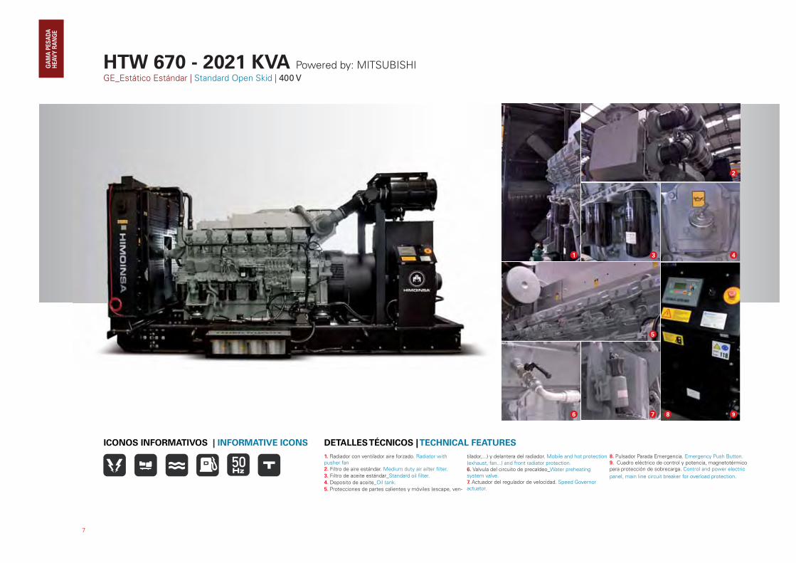
HTW 670 - 2021 KVA Powered by: MITSUBISHIGE_Estático Estándar | Standard Open Skid | 400 V
7
1. Radiador con ventilador aire forzado. Radiator with pusher fan2. Filtro de aire estándar. Medium duty air ailter filter.
3. Filtro de aceite estándar_Standard oil filter.
4. Deposito de aceite_Oil tank.
5. Protecciones de partes calientes y móviles (escape, ven-
tilador,...) y delantera del radiador. Mobile and hot protection
(exhaust, fan...) and front radiator protection.6. Valvula del circuito de precaldeo_Water preheating system valve.7. Actuador del regulador de velocidad. Speed Governor actuator.
8. Pulsador Parada Emergencia. Emergency Push Button.9. Cuadro eléctrico de control y potencia, magnetotérmico para protección de sobrecarga. Control and power electric
panel, main line circuit breaker for overload protection.
DETALLES TÉCNICOS | TECHNICAL FEATURESICONOS INFORMATIVOS | INFORMATIVE ICONS
6 7
1
5
3
2
4
8 9
8
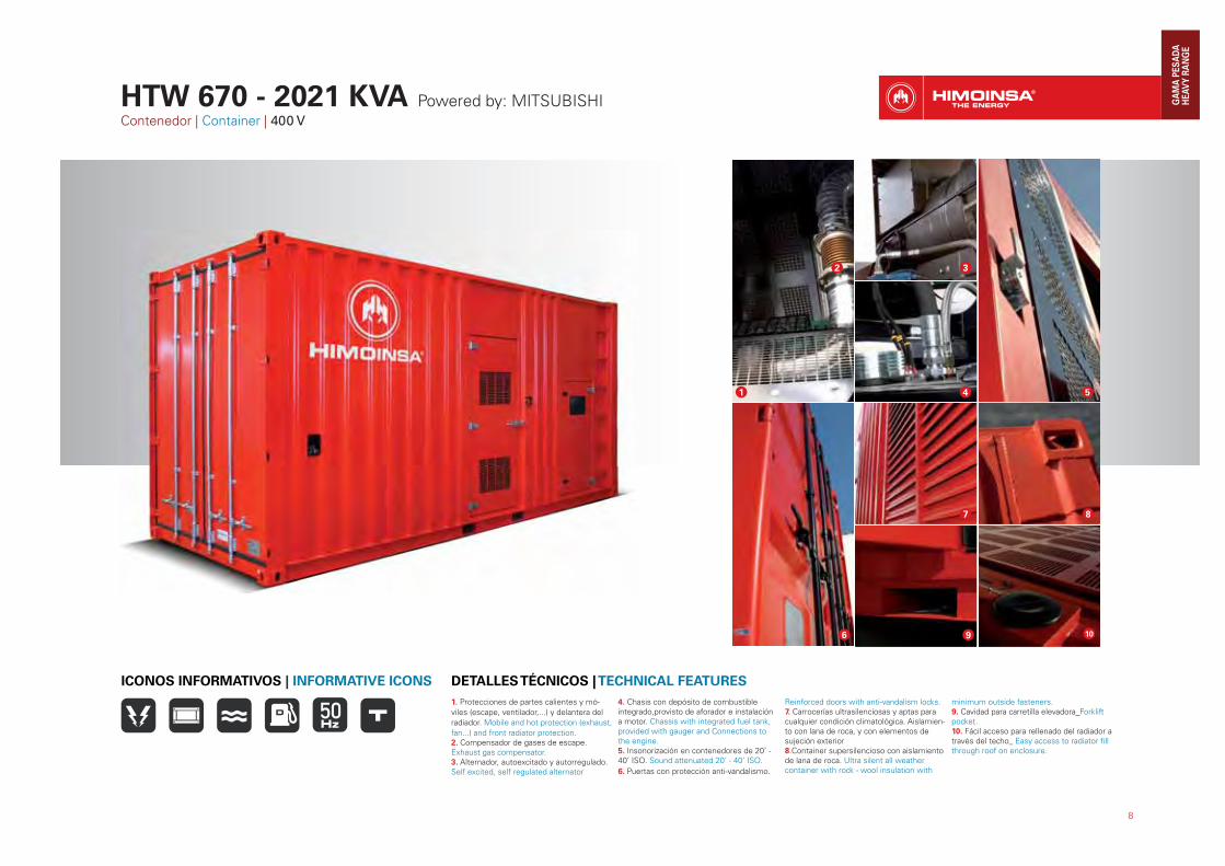
1. Protecciones de partes calientes y mó-
viles (escape, ventilador,...) y delantera del
radiador. Mobile and hot protection (exhaust,
fan...) and front radiator protection.2. Compensador de gases de escape. Exhaust gas compensator.3. Alternador, autoexcitado y autorregulado. Self excited, self regulated alternator
4. Chasis con depósito de combustible integrado,provisto de aforador e instalación a motor. Chassis with integrated fuel tank, provided with gauger and Connections to the engine.5. Insonorización en contenedores de 20’ - 40’ ISO. Sound attenuated 20’ - 40’ ISO.
6. Puertas con protección anti-vandalismo.
Reinforced doors with anti-vandalism locks.7. Carrocerías ultrasilenciosas y aptas para cualquier condición climatológica. Aislamien-to con lana de roca, y con elementos de sujeción exterior 8.Container supersilencioso con aislamiento de lana de roca. Ultra silent all weather container with rock - wool insulation with
minimum outside fasteners.9. Cavidad para carretilla elevadora_Forklift pocket.10. Fácil acceso para rellenado del radiador a través del techo_ Easy access to radiator fill through roof on enclosure.
DETALLES TÉCNICOS | TECHNICAL FEATURESICONOS INFORMATIVOS | INFORMATIVE ICONS
1
2 3
54
6
8
9 10
7
HTW 670 - 2021 KVA Powered by: MITSUBISHIContenedor | Container | 400 V
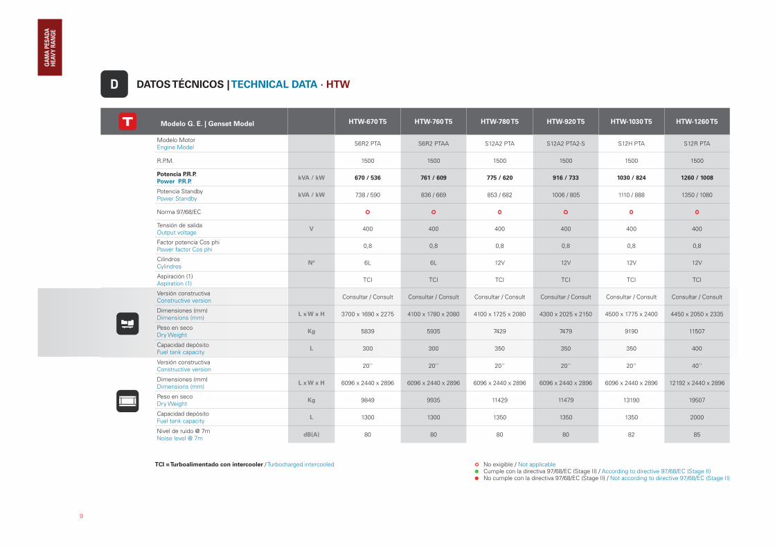
DATOS TÉCNICOS | TECHNICAL DATA · HTW
Modelo G. E. | Genset Model HTW-670 T5 HTW-760 T5 HTW-780 T5 HTW-920 T5 HTW-1030 T5 HTW-1260 T5
Modelo MotorEngine Model
S6R2 PTA S6R2 PTAA S12A2 PTA S12A2 PTA2-S S12H PTA S12R PTA
R.P.M. 1500 1500 1500 1500 1500 1500
Potencia P.R.P.
Power P.R.P. kVA / kW 670 / 536 761 / 609 775 / 620 916 / 733 1030 / 824 1260 / 1008
Potencia StandbyPower Standby
kVA / kW 738 / 590 836 / 669 853 / 682 1006 / 805 1110 / 888 1350 / 1080
Norma 97/68/EC
Tensión de salidaOutput voltage
V 400 400 400 400 400 400
Factor potencia Cos phiPower factor Cos phi
0,8 0,8 0,8 0,8 0,8 0,8
CilindrosCylindres
Nº 6L 6L 12V 12V 12V 12V
Aspiración (1)Aspiration (1)
TCI TCI TCI TCI TCI TCI
Versión constructivaConstructive version
Consultar / Consult Consultar / Consult Consultar / Consult Consultar / Consult Consultar / Consult Consultar / Consult
Dimensiones (mm)Dimensions (mm)
L x W x H 3700 x 1690 x 2275 4100 x 1780 x 2080 4100 x 1725 x 2080 4300 x 2025 x 2150 4500 x 1775 x 2400 4450 x 2050 x 2335
Peso en secoDry Weight
Kg 5839 5935 7429 7479 9190 11507
Capacidad depósitoFuel tank capacity
L 300 300 350 350 350 400
Versión constructivaConstructive version
20'' 20'' 20'' 20'' 20'' 40''
Dimensiones (mm)Dimensions (mm)
L x W x H 6096 x 2440 x 2896 6096 x 2440 x 2896 6096 x 2440 x 2896 6096 x 2440 x 2896 6096 x 2440 x 2896 12192 x 2440 x 2896
Peso en secoDry Weight
Kg 9849 9935 11429 11479 13190 19507
Capacidad depósitoFuel tank capacity
L 1300 1300 1350 1350 1350 2000
Nivel de ruido @ 7mNoise level @ 7m
dB(A) 80 80 80 80 82 85
9
D
TCI = Turboalimentado con intercooler / Turbocharged intercooled No exigible / Not applicable Cumple con la directiva 97/68/EC (Stage II) / According to directive 97/68/EC (Stage II) No cumple con la directiva 97/68/EC (Stage II) / Not according to directive 97/68/EC (Stage II)

No exigible / Not applicable Cumple con la directiva 97/68/EC (Stage II) / According to directive 97/68/EC (Stage II) No cumple con la directiva 97/68/EC (Stage II) / Not according to directive 97/68/EC (Stage II)
10
Modelo G. E. | Genset Model HTW-1390 T5 HTW-1530 T5 HTW-1745 T5 HTW-1900 T5 HTW-2030 T5
Modelo MotorEngine Model
S12R PTA2 S12R PTAA2 S16R PTA S16R PTA2 S16R PTAA2
R.P.M. 1500 1500 1500 1500 1500
Potencia P.R.P.
Power P.R.P. kVA / kW 1382 / 1106 1523 / 1218 1736 / 1389 1892 / 1514 2021 / 1617
Potencia StandbyPower Standby
kVA / kW 1500 / 1200 1660 / 1328 1900 / 1520 2035 / 1628 2250 / 1800
Norma 97/68/EC
Tensión de salidaOutput voltage
V 400 400 400 400 400
Factor potencia Cos phiPower factor Cos phi
0,8 0,8 0,8 0,8 0,8
CilindrosCylindres
Nº 12V 12V 16V 16V 16V
Aspiración (1)Aspiration (1)
TCI TCI TCI TCI TCI
Versión constructivaConstructive version
Consultar / Consult Consultar / Consult Consultar / Consult Consultar / Consult Consultar / Consult
Dimensiones (mm)Dimensions (mm)
L x W x H 4450 x 2050 x 2335 5300 x 2100 x 2600 5260 x 2100 x 2425 5275 x 2100 x 2875 6100 x 2200 x 2870
Peso en secoDry Weight
Kg 11787 12219 15200 15123 16128
Capacidad depósitoFuel tank capacity
L 400 400 450 450 450
Versión constructivaConstructive version
40'' 40'' 40'' 40'' 40''
Dimensiones (mm)Dimensions (mm)
L x W x H 12192 x 2440 x 2896 12192 x 2440 x 2896 12192 x 2440 x 2896 12192 x 2440 x 2896 12192 x 2440 x 2896
Peso en secoDry Weight
Kg 19787 20219 23200 23123 24128
Capacidad depósitoFuel tank capacity
L 2000 2000 2000 2000 2000
Nivel de ruido @ 7mNoise level @ 7m
dB(A) 86 87 88 90 90
TCI = Turboalimentado con intercooler / Turbocharged intercooled
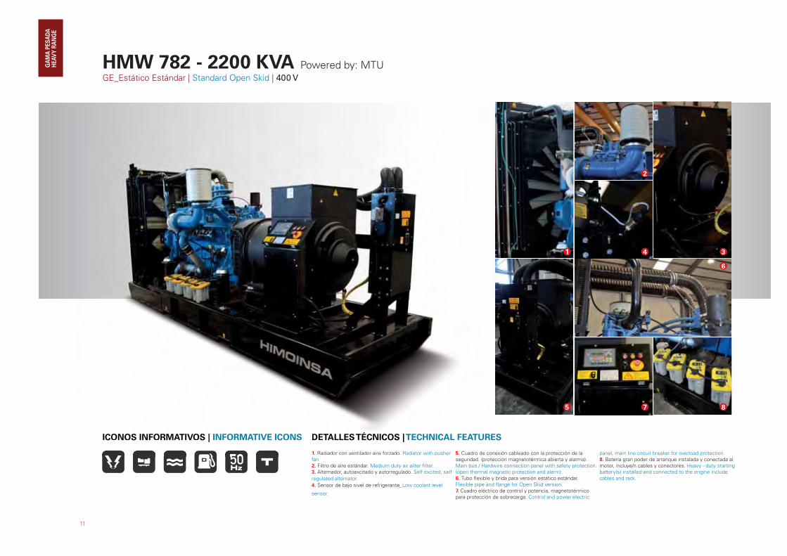
HMW 782 - 2200 KVA Powered by: MTUGE_Estático Estándar | Standard Open Skid | 400 V
11
1. Radiador con ventilador aire forzado. Radiator with pusher fan2. Filtro de aire estándar. Medium duty air ailter filter.3. Alternador, autoexcitado y autorregulado. Self excited, self
regulated alternator.
4. Sensor de bajo nivel de refrigerante_Low coolant level
sensor.
5. Cuadro de conexión cableado con la protección de la seguridad. (protección magnetotérmica abierta y alarma).Main bus / Hardwire connection panel with safety protection. (open thermal magnetic protection and alarm).6. Tubo flexible y brida para versión estático estándar. Flexible pipe and flange for Open Skid version.7. Cuadro eléctrico de control y potencia, magnetotérmico para protección de sobrecarga. Control and power electric
panel, main line circuit breaker for overload protection. 8. Batería gran poder de arranque instalada y conectada al motor, incluye/n cables y conectores. Heavy - duty starting battery(s) installed and connected to the engine include cables and rack.
DETALLES TÉCNICOS | TECHNICAL FEATURESICONOS INFORMATIVOS | INFORMATIVE ICONS
1
2
34
8
6
75
1. Radiador con ventilador aire forzado. Radiator with pusher 5. Cuadro de conexión cable
DETALLES TÉCNICOS | TECHNICAL FEATURESICONOS INFORMATIVOS | INFORMATIVE ICONS
12
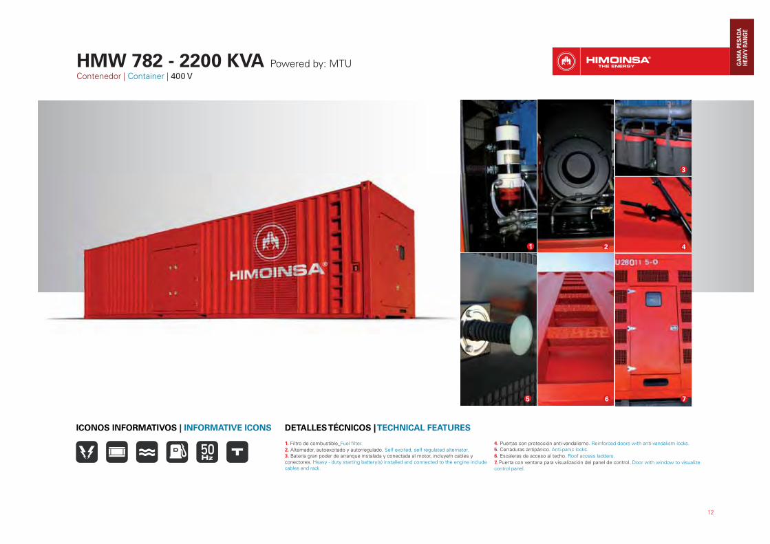
1. Filtro de combustible_Fuel filter.
2. Alternador, autoexcitado y autorregulado. Self excited, self regulated alternator.3. Batería gran poder de arranque instalada y conectada al motor, incluye/n cables y conectores. Heavy - duty starting battery(s) installed and connected to the engine include cables and rack.
4. Puertas con protección anti-vandalismo. Reinforced doors with anti-vandalism locks.5. Cerraduras antipánico. Anti-panic locks.
6. Escaleras de acceso al techo. Roof access ladders.
7. Puerta con ventana para visualización del panel de control. Door with window to visualize control panel.
DETALLES TÉCNICOS | TECHNICAL FEATURESICONOS INFORMATIVOS | INFORMATIVE ICONS
HMW 782 - 2200 KVA Powered by: MTUContenedor | Container | 400 V
1 2
3
6 7
4
5
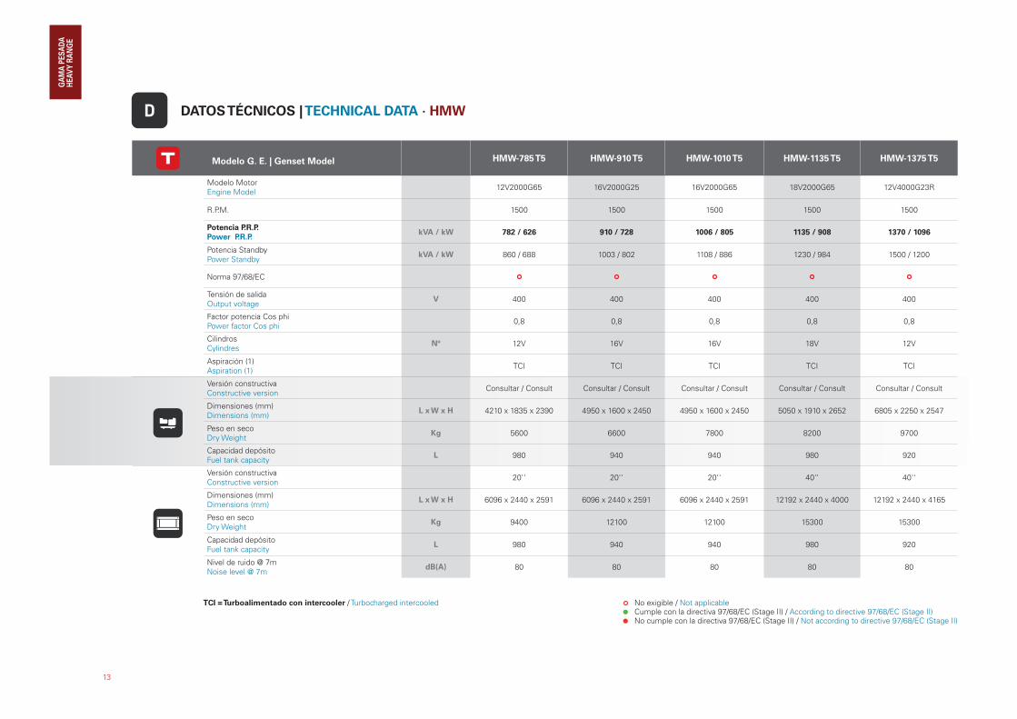
DATOS TÉCNICOS | TECHNICAL DATA · HMW
13
Modelo G. E. | Genset Model HMW-785 T5 HMW-910 T5 HMW-1010 T5 HMW-1135 T5 HMW-1375 T5
Modelo MotorEngine Model
12V2000G65 16V2000G25 16V2000G65 18V2000G65 12V4000G23R
R.P.M. 1500 1500 1500 1500 1500
Potencia P.R.P.
Power P.R.P. kVA / kW 782 / 626 910 / 728 1006 / 805 1135 / 908 1370 / 1096
Potencia StandbyPower Standby
kVA / kW 860 / 688 1003 / 802 1108 / 886 1230 / 984 1500 / 1200
Norma 97/68/EC
Tensión de salidaOutput voltage
V 400 400 400 400 400
Factor potencia Cos phiPower factor Cos phi
0,8 0,8 0,8 0,8 0,8
CilindrosCylindres
Nº 12V 16V 16V 18V 12V
Aspiración (1)Aspiration (1)
TCI TCI TCI TCI TCI
Versión constructivaConstructive version
Consultar / Consult Consultar / Consult Consultar / Consult Consultar / Consult Consultar / Consult
Dimensiones (mm)Dimensions (mm)
L x W x H 4210 x 1835 x 2390 4950 x 1600 x 2450 4950 x 1600 x 2450 5050 x 1910 x 2652 6805 x 2250 x 2547
Peso en secoDry Weight
Kg 5600 6600 7800 8200 9700
Capacidad depósitoFuel tank capacity
L 980 940 940 980 920
Versión constructivaConstructive version
20'' 20'' 20'' 40'' 40''
Dimensiones (mm)Dimensions (mm)
L x W x H 6096 x 2440 x 2591 6096 x 2440 x 2591 6096 x 2440 x 2591 12192 x 2440 x 4000 12192 x 2440 x 4165
Peso en secoDry Weight
Kg 9400 12100 12100 15300 15300
Capacidad depósitoFuel tank capacity
L 980 940 940 980 920
Nivel de ruido @ 7mNoise level @ 7m
dB(A) 80 80 80 80 80
D
TCI = Turboalimentado con intercooler / Turbocharged intercooled No exigible / Not applicable Cumple con la directiva 97/68/EC (Stage II) / According to directive 97/68/EC (Stage II) No cumple con la directiva 97/68/EC (Stage II) / Not according to directive 97/68/EC (Stage II)
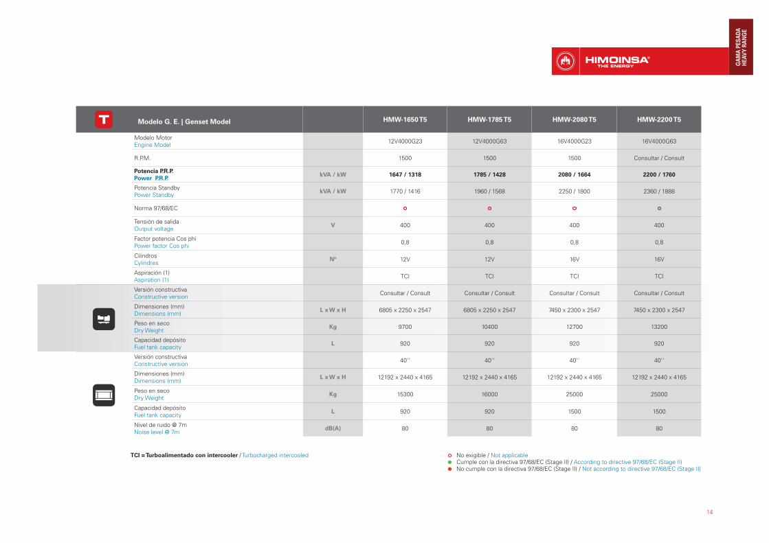
14
Modelo G. E. | Genset Model HMW-1650 T5 HMW-1785 T5 HMW-2080 T5 HMW-2200 T5
Modelo MotorEngine Model
12V4000G23 12V4000G63 16V4000G23 16V4000G63
R.P.M. 1500 1500 1500 Consultar / Consult
Potencia P.R.P.
Power P.R.P. kVA / kW 1647 / 1318 1785 / 1428 2080 / 1664 2200 / 1760
Potencia StandbyPower Standby
kVA / kW 1770 / 1416 1960 / 1568 2250 / 1800 2360 / 1888
Norma 97/68/EC
Tensión de salidaOutput voltage
V 400 400 400 400
Factor potencia Cos phiPower factor Cos phi
0,8 0,8 0,8 0,8
CilindrosCylindres
Nº 12V 12V 16V 16V
Aspiración (1)Aspiration (1)
TCI TCI TCI TCI
Versión constructivaConstructive version
Consultar / Consult Consultar / Consult Consultar / Consult Consultar / Consult
Dimensiones (mm)Dimensions (mm)
L x W x H 6805 x 2250 x 2547 6805 x 2250 x 2547 7450 x 2300 x 2547 7450 x 2300 x 2547
Peso en secoDry Weight
Kg 9700 10400 12700 13200
Capacidad depósitoFuel tank capacity
L 920 920 920 920
Versión constructivaConstructive version
40'' 40'' 40'' 40''
Dimensiones (mm)Dimensions (mm)
L x W x H 12192 x 2440 x 4165 12192 x 2440 x 4165 12192 x 2440 x 4165 12192 x 2440 x 4165
Peso en secoDry Weight
Kg 15300 16000 25000 25000
Capacidad depósitoFuel tank capacity
L 920 920 1500 1500
Nivel de ruido @ 7mNoise level @ 7m
dB(A) 80 80 80 80
TCI = Turboalimentado con intercooler / Turbocharged intercooled No exigible / Not applicable Cumple con la directiva 97/68/EC (Stage II) / According to directive 97/68/EC (Stage II) No cumple con la directiva 97/68/EC (Stage II) / Not according to directive 97/68/EC (Stage II)
15
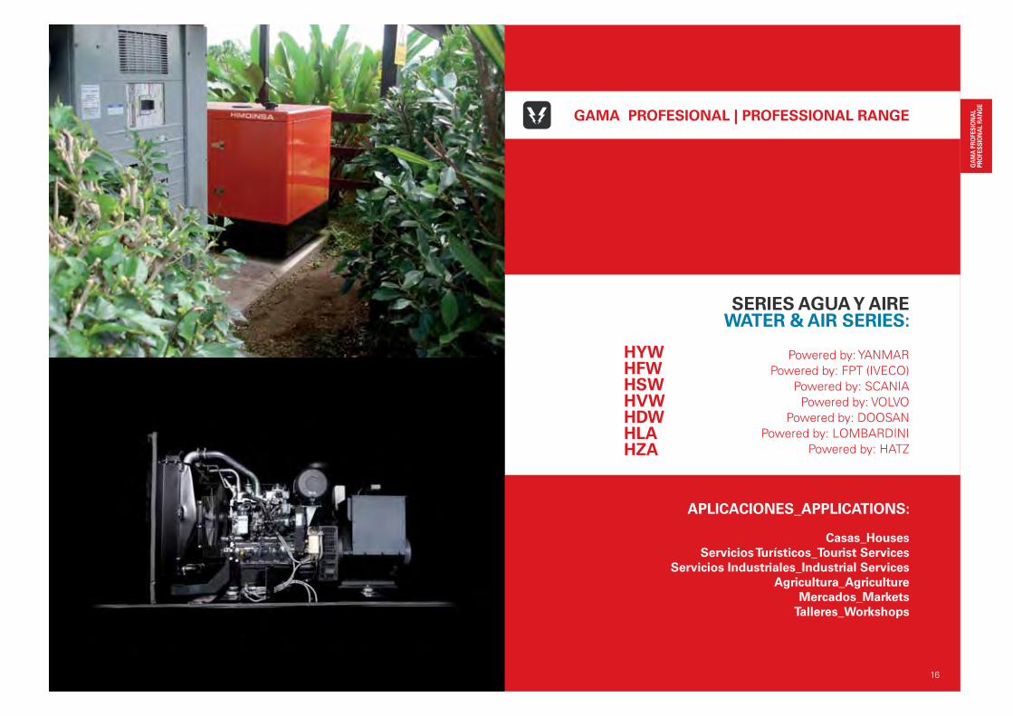
APLICACIONES_APPLICATIONS:
Casas_Houses
Servicios Turísticos_Tourist Services
Servicios Industriales_Industrial Services
Agricultura_Agriculture
Mercados_Markets
Talleres_Workshops
16
GAMA PROFESIONAL | PROFESSIONAL RANGE
SERIES AGUA Y AIREWATER & AIR SERIES:
Powered by: YANMAR
Powered by: FPT (IVECO)
Powered by: SCANIA
Powered by: VOLVO
Powered by: DOOSAN
Powered by: LOMBARDINI
Powered by: HATZ
HYWHFWHSWHVWHDWHLAHZA
17
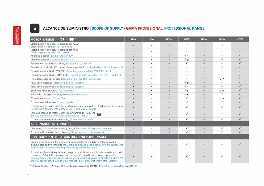
MOTOR_ENGINE HLA HZA HYW HFW HSW HVW HDW
Motor diesel, 4 tiempos, refrigerado por AGUADiesel engine, 4 strokes, WATER cooled
• • √ √ √ √ √
Motor diesel, 4 tiempos, refrigerado por AIREDiesel engine, 4 strokes, AIR cooled
√ √ • • • • •
Arranque eléctrico 12V_Electric start 12V � √ √ √ (1) • • •
Arranque eléctrico 24V_Electric start 24V • • • √ (2) √ √ √
Radiador con ventilador soplante_Radiator with pusher fan • • � � � • �
Radiador tropicalizado 45º con ventilador soplante_Tropicalized radiator 45º with pusher fan • • • • • � •
Filtro decantador (NIVEL VISIBLE)_Decanting water pre filter (VISIBLE LEVEL) • • � • � • •
Filtro decantador (NIVEL NO VISIBLE)_Decanting water pre filter (LEVEL NOT VISIBLE) • • • � • • �
Filtro decantador con sensor_Decanting water pre filter with sensor • • • • • √ (7) •
Regulación mecánica_Mechanical engine regulation � � � √ (3) • • •
Regulación electrónica_Electronic engine regulation • • • √ (4) � � �
Bulbos de ATA / BPA_HWT / LOP senders • • • √ (5) � √ (8) �
Sensor de nivel agua radiador_Low coolant level sensor • • • ��(6) � √ •
Filtro de aire en seco_Dry air filter � � � � � √ (9) �
Protecciones del escape_Exhaust guards � � � � � � �
Protecciones de partes calientes y móviles (escape, ventilador,….) y delantera de radiador Hot & mobile components (exhaust, fan,…) and radiator guards
• • � � � � �
Salida de escape de motor y silencioso industrial de -15 dB (A)Exhaust engine outlet and industrial silencer of -15dB(A)
� � � � � � �
Kit de extracción de aceite del cárter_Oil sump extraction kit • • • � � � �
ALTERNADOR_ALTERNATOR
Alternador, autoexcitado y autorregulado_Self excited, self regulated alternator � � � � � � �
Protección IP23, Aislamiento clase H_IP23 protection, Isolation class H � � � � � � �
CONTROL Y POTENCIA_CONTROL AND POWER PANEL
Cuadro eléctrico de control y potencia, con aparatos de medida y central de control (según necesidad y configuración)_Control and power electric panel, With measurements devices and Controller (according to necessity and configuration)
� � � � � � �
Protección diferencial regulable en tiempo y sensibilidad, suministrada de serie en todos los cuadros M5 y AS5 con protección magnetotérmica (Otras versiones opcional)Differential protection adjustable in time and sensibility, Supplied as standard in all the M5 and AS5 control panels with Thermal magnetic protection (Optional in other versions)
• • � � � � �
S ALCANCE DE SUMINISTRO | SCOPE OF SUPPLY · GAMA PROFESIONAL_PROFESSIONAL RANGE
+
� Estándar_Standard • No disponible (consultar opcionales páginas 100-109) • Unavailable (see optionals on pages 100-109)
*
18
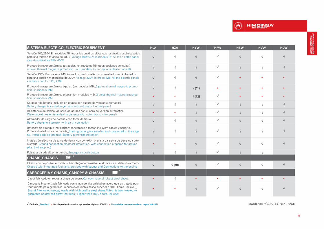
SISTEMA ELÉCTRICO_ELECTRIC EQUIPMENT HLA HZA HYW HFW HSW HVW HDW
Tensión 400/230V. En modelos T5: todos los cuadros eléctricos reseñados están basados para una tensión trifásica de 400V_Voltage 400/230V. In models T5: All the electric panel-sare described for 3Ph, 400V.
√ √ √ √ √ √ √
Protección magnetotérmica tetrapolar. (en modelos T5) (otras opciones consultar)4 Poles thermal magnetic protection. (in T5 models) (other options please consult)
√ √ √ √ √ √ √
Tensión 230V. En modelos M5: todos los cuadros eléctricos reseñados están basados para una tensión monofásica de 230V_Voltage 230V. In model M5: All the electric panels are described for 1Ph, 230V.
√ √ √ √ • • •
Protección magnetotérmica bipolar. (en modelos M5)_2 poles thermal magnetic protec-tion. (in models M5)
√ √ √ (11) • • • •
Protección magnetotérmica tripolar. (en modelos M5)_3 poles thermal magnetic protec-tion. (in models M5)
• • √ (12) √ • • •
Cargador de batería (incluido en grupos con cuadro de versión automática)Battery charger (included in gensets with automatic Control panel)
√ √ √ √ √ √ √
Resistencia de caldeo (de serie en grupos con cuadro de versión automática)Water jacket heater. (standard in gensets with automatic control panel)
• • √ √ √ √ √
Alternador de carga de baterías con toma de tierraBattery charging alternator with earth connection
√ √ √ √ √ √ √
Batería/s de arranque instaladas y conectadas a motor, incluye/n cables y soporte.Protección de bornas de batería_Starting battery/ies installed and connected to the engi-ne. Include cables and rack. Battery terminals protection.
√ √ √ √ √ √ √
Instalación eléctrica de toma de tierra, con conexión prevista para pica de tierra no sumi-nistrada_Ground connection electrical installation, with connection prepared for ground pike. (not supplied)
• • √ √ √ √ √
Pulsador parada de emergencia_Emergency push button √ √ √ √ √ √
CHASIS_CHASSIS
Chasis con depósito de combustible integrado,provisto de aforador e instalación a motor Chassis with integrated fuel tank, provided with gauger and Connections to the engine
√ √ (10) √ √ √ √ √
CARROCERIA Y CHASIS_CANOPY & CHASSIS
Capot fabricado en robusta chapa de acero_Canopy made of robust steel sheet. • √ • • • • •
Carrocería insonorizada fabricada con chapa de alta calidad en acero que es tratada pos-teriormente para garantizar un ensayo de niebla salina superior a 1000 horas. Incluye:_ Sound Attenuated canopy made with high quality steel sheet, Which is later treated to guarantee neutral salt spray test result Higher than 1000 hours. Include:
• • √ √ √ √ √
SIGUIENTE PÁGINA >> NEXT PAGE� Estándar_Standard • No disponible (consultar opcionales páginas 100-109) • Unavailable (see optionals on pages 100-109)
*
*
19
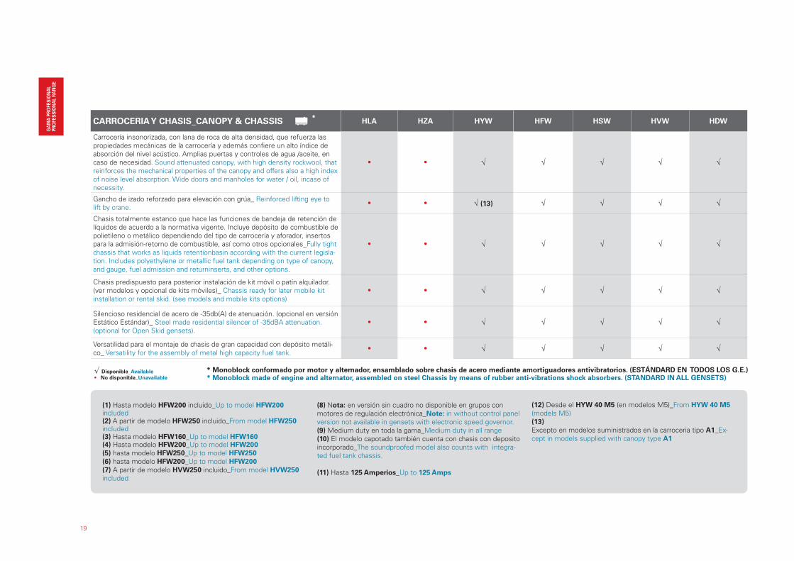
CARROCERIA Y CHASIS_CANOPY & CHASSIS HLA HZA HYW HFW HSW HVW HDW
Carrocería insonorizada, con lana de roca de alta densidad, que refuerza las propiedades mecánicas de la carrocería y además confiere un alto índice de absorción del nivel acústico. Amplias puertas y controles de agua /aceite, en caso de necesidad. Sound attenuated canopy, with high density rockwool, that reinforces the mechanical properties of the canopy and offers also a high index of noise level absorption. Wide doors and manholes for water / oil, incase of necessity.
• • √ √ √ √ √
Gancho de izado reforzado para elevación con grúa_ Reinforced lifting eye to lift by crane.
• • √ (13) √ √ √ √
Chasis totalmente estanco que hace las funciones de bandeja de retención de líquidos de acuerdo a la normativa vigente. Incluye depósito de combustible de polietileno o metálico dependiendo del tipo de carrocería y aforador, insertos para la admisión-retorno de combustible, así como otros opcionales_Fully tight chassis that works as liquids retentionbasin according with the current legisla-tion. Includes polyethylene or metallic fuel tank depending on type of canopy, and gauge, fuel admission and returninserts, and other options.
• • √ √ √ √ √
Chasis predispuesto para posterior instalación de kit móvil o patín alquilador. (ver modelos y opcional de kits móviles)_ Chassis ready for later mobile kit installation or rental skid. (see models and mobile kits options)
• • √ √ √ √ √
Silencioso residencial de acero de -35db(A) de atenuación. (opcional en versión Estático Estándar)_ Steel made residential silencer of -35dBA attenuation. (optional for Open Skid gensets).
• • √ √ √ √ √
Versatilidad para el montaje de chasis de gran capacidad con depósito metáli-co_ Versatility for the assembly of metal high capacity fuel tank.
• • √ √ √ √ √
��(1) Hasta modelo HFW200 incluido_Up to model HFW200 included(2) A partir de modelo HFW250 incluido_From model HFW250 included(3) Hasta modelo HFW160_Up to model HFW160(4) Hasta modelo HFW200_Up to model HFW200
(5) hasta modelo HFW250_Up to model HFW250
(6) hasta modelo HFW200_Up to model HFW200
(7) A partir de modelo HVW250 incluido_From model HVW250
included
(8) Nota: en versión sin cuadro no disponible en grupos con motores de regulación electrónica_Note: in without control panel version not available in gensets with electronic speed governor.(9) Medium duty en toda la gama_Medium duty in all range(10) El modelo capotado también cuenta con chasis con deposito incorporado_The soundproofed model also counts with integra-ted fuel tank chassis.
(11) Hasta 125 Amperios_Up to 125 Amps
(12) Desde el HYW 40 M5 (en modelos M5)_From HYW 40 M5
(models M5)(13)
Excepto en modelos suministrados en la carroceria tipo A1_Ex-cept in models supplied with canopy type A1
* Monoblock conformado por motor y alternador, ensamblado sobre chasis de acero mediante amortiguadores antivibratorios. (ESTÁNDARD EN TODOS LOS G.E.)* Monoblock made of engine and alternator, assembled on steel Chassis by means of rubber anti-vibrations shock absorbers. (STANDARD IN ALL GENSETS)
� Disponible_Available• No disponible_Unavailable
*
20
HYW 7,8 - 41 KVA Powered by: YANMARGE_Estático Estándar | Standard Open Skid | 400 - 230 V
21
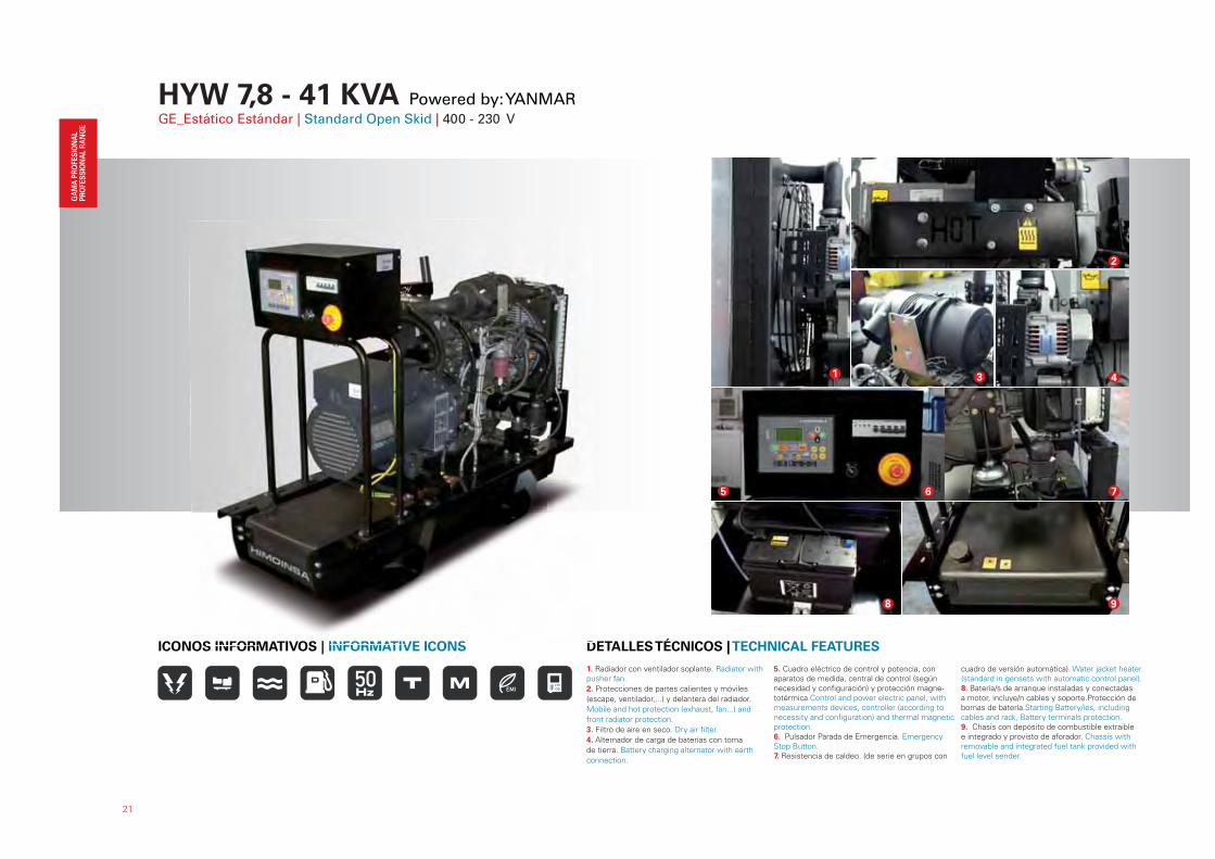
1. Radiador con ventilador soplante. Radiator with pusher fan.
2. Protecciones de partes calientes y móviles
(escape, ventilador,...) y delantera del radiador.
Mobile and hot protection (exhaust, fan...) and
front radiator protection.
3. Filtro de aire en seco. Dry air filter.
4. Alternador de carga de baterías con toma
de tierra. Battery charging alternator with earth
connection.
5. Cuadro eléctrico de control y potencia, con aparatos de medida, central de control (según necesidad y configuración) y protección magne-totérmica.Control and power electric panel, with measurements devices, controller (according to necessity and configuration) and thermal magnetic protection.6. Pulsador Parada de Emergencia. Emergency Stop Button.7. Resistencia de caldeo. (de serie en grupos con
cuadro de versión automática). Water jacket heater. (standard in gensets with automatic control panel).8. Batería/s de arranque instaladas y conectadas a motor, incluye/n cables y soporte.Protección de bornas de batería.Starting Battery/ies, including cables and rack, Battery terminals protection.9. Chasis con depósito de combustible extraible e integrado y provisto de aforador. Chassis with removable and integrated fuel tank provided with fuel level sender.
DETALLES TÉCNICOS | TECHNICAL FEATURESICONOS INFORMATIVOS | INFORMATIVE ICONS
1 3
2
4
7
8 9
DOS INFORMATIVOS | INFORMATIVE ICONS
65
22
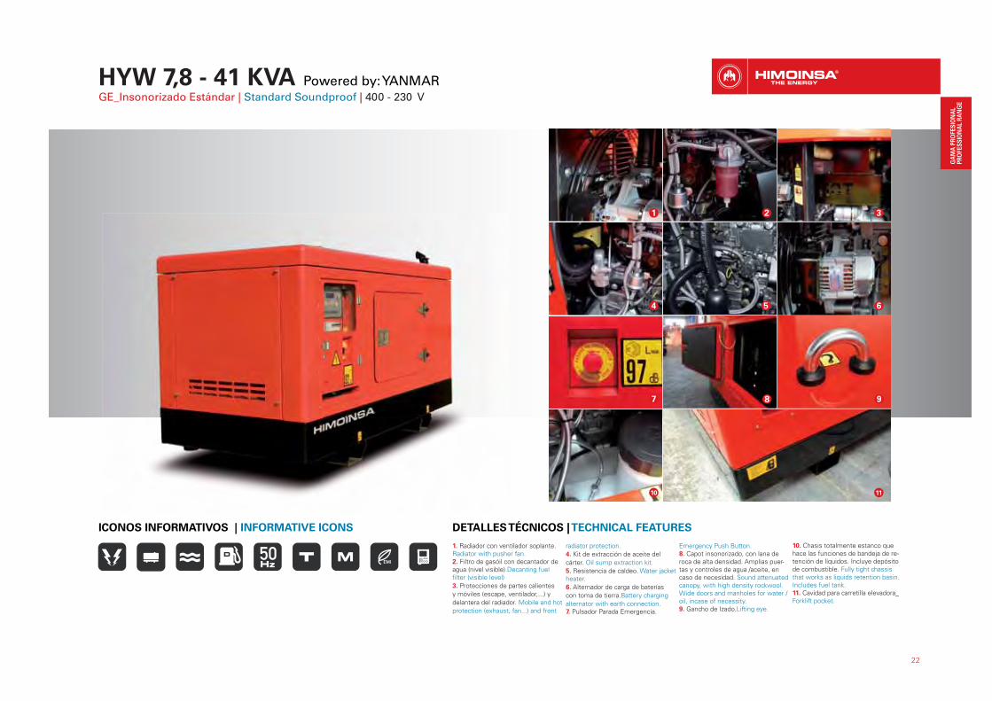
1. Radiador con ventilador soplante. Radiator with pusher fan.2. Filtro de gasóil con decantador de agua (nivel visible).Decanting fuel filter (visible level)
3. Protecciones de partes calientes
y móviles (escape, ventilador,...) y
delantera del radiador. Mobile and hot
protection (exhaust, fan...) and front
radiator protection.
4. Kit de extracción de aceite del
cárter. Oil sump extraction kit.
5. Resistencia de caldeo. Water jacket heater.
6. Alternador de carga de baterías
con toma de tierra.Battery charging
alternator with earth connection.7. Pulsador Parada Emergencia.
Emergency Push Button.8. Capot insonorizado, con lana de roca de alta densidad. Amplias puer-tas y controles de agua /aceite, en caso de necesidad. Sound attenuated canopy, with high density rockwool. Wide doors and manholes for water / oil, incase of necessity.9. Gancho de Izado.Lifting eye.
10. Chasis totalmente estanco que hace las funciones de bandeja de re-tención de líquidos. Incluye depósito de combustible. Fully tight chassis that works as liquids retention basin. Includes fuel tank.11. Cavidad para carretilla elevadora_Forklift pocket.
DETALLES TÉCNICOS | TECHNICAL FEATURESICONOS INFORMATIVOS | INFORMATIVE ICONS
5
2 3
4
1
6
7 8 9
10 11
HYW 7,8 - 41 KVA Powered by: YANMARGE_Insonorizado Estándar | Standard Soundproof | 400 - 230 V

23
Modelo G. E. | Genset Model HYW-8 T5 HYW-13 T5 HYW-17 T5 HYW-20 T5 HYW-35 T5 HYW-45 T5
Modelo Motor_Engine Model 3TNV76 3TNV88 4TNV88 4TNV84T 4TNV98 4TNV98T
R.P.M. 1500 1500 1500 1500 1500 1500
Potencia P.R.P._Power P.R.P. kVA / kW 7,8 / 6 12,5 / 10 17 / 13,7 20 / 16 34 / 27 41 / 33
Potencia Standby_Power Standby kVA / kW 8,6 / 6,9 13,4 / 10,7 18 / 14,6 22 / 18 37 / 30 45 / 36
Norma 97/68/EC
Tensión de salida_Output voltage V 400 400 400 400 400 400
Factor potencia Cos phi_Power factor Cos phi 0,8 0,8 0,8 0,8 0,8 0,8
Cilindros_Cylindres Nº 3L 3L 4L 4L 4L 4L
Aspiración (1)_Aspiration (1) NA NA NA TC NA TC
Regulador_Governor M M M M M M
Versión constructiva_Constructive version K1 K1 K1 K2 K3 K3
Dimensiones (mm)_Dimensions (mm) L x W x H 1450 x 620 x 1286 1450 x 620 x 1286 1450 x 620 x 1286 1700 x 620 x 1286 1850 x 780 x 1500 1850 x 780 x 1500
Peso_Weight Kg 307 362 362 416 545 626
Capacidad depósito_Fuel tank capacity L 60 60 60 76 120 120
Versión constructiva_Constructive version A1 A1 A2 A2 B1 C
Dimensiones (mm)_Dimensions (mm) L x W x H 1475 x 750 x 1110 1475 x 750 x 1110 1920 x 900 x 1230 1920 x 900 x 1230 2000 x 950 x 1270 2250 x 1050 x 1450
Peso_Weight Kg 611 666 701 720 905 1081
Capacidad depósito_Fuel tank capacity L 23 23 38 38 60 65
Nivel de ruido @ 7m_Noise level @ 7m dB(A) 64 59 60 57 63 62
Dimensiones (mm)_Dimensions (mm) L x W x H N.A. N.A. 3230 x 1400 x 1560 3230 x 1400 x 1560 3300 x 1400x 1600 3550 x 1600 x 1730
Peso_Weight Kg N.A. N.A. 831 850 1029 1215
DATOS TÉCNICOS | TECHNICAL DATA · HYWD
(1) NA = Aspiración Natural / Natural Aspirated; TC = Turboalimentado / Turbocharged * Datos referidos a Kit móvil de desplazamiento lento (Kit móvil homologado consultar)* Data relating to Low speed trailers (Please consult for High speed trailers)
No exigible / Not applicable Cumple con la directiva 97/68/EC (Stage II) / According to directive 97/68/EC (Stage II) No cumple con la directiva 97/68/EC (Stage II) / Not according to directive 97/68/EC (Stage II)
*

24
Modelo G. E. | Genset Model HYW-9 M5 HYW-13 M5 HYW-20 M5 HYW-30 M5 HYW-40 M5
Modelo Motor_Engine Model 3TNV76 3TNV88 4TNV88 4TNV98 4TNV98T
R.P.M. 1500 1500 1500 1500 1500
Potencia P.R.P._Power P.R.P. kVA / kW 8,4 / 6,7 12,8 / 10,3 18 / 14,4 25 / 20 34 / 27
Potencia Standby_Power Standby kVA / kW 9,2 / 7,4 13,8 / 11 19 / 15,2 26 / 21 36 / 28
Norma 97/68/EC
Tensión de salida_Output voltage V 230 230 230 230 230
Factor potencia Cos phi_Power factor Cos phi 0,8 0,8 0,8 0,8 0,8
Cilindros_Cylindres Nº 3L 3L 4L 4L 4L
Aspiración (1)_Aspiration (1) NA NA NA NA TC
Regulador_Governor M M M M M
Versión constructiva_Constructive version K1 K1 K1 K3 K3
Dimensiones (mm)_Dimensions (mm) L x W x H 1450 x 620 x 1286 1450 x 620 x 1286 1450 x 620 x 1286 1850 x 780 x 1500 1850 x 780 x 1500
Peso_Weight Kg 328 387 455 604 702
Capacidad depósito_Fuel tank capacity L 60 60 60 120 120
Versión constructiva_Constructive version A1 A1 A2 B1 C
Dimensiones (mm)_Dimensions (mm) L x W x H 1475 x 750 x 1110 1475 x 750 x 1110 1920 x 900 x 1230 2000 x 950 x 1270 2250 x 1050 x 1450
Peso_Weight Kg 615 730 750 545 600
Capacidad depósito_Fuel tank capacity L 23 23 38 60 65
Nivel de ruido @ 7m_Noise level @ 7m dB(A) 64 59 57 63 62
Dimensiones (mm)_Dimensions (mm) L x W x H N.A. N.A. 3230 x 1400 x 1560 3300 x 1400x 1600 3550 x 1600 x 1730
Peso_Weight Kg N.A. N.A. 890 1090 1274
No exigible / Not applicable Cumple con la directiva 97/68/EC (Stage II) / According to directive 97/68/EC (Stage II) No cumple con la directiva 97/68/EC (Stage II) / Not according to directive 97/68/EC (Stage II)
(1) NA = Aspiración Natural / Natural Aspirated; TC = Turboalimentado / Turbocharged * Datos referidos a Kit móvil de desplazamiento lento (Kit móvil homologado consultar)* Data relating to Low speed trailers (Please consult for High speed trailers)
*
HFW 60 - 400 KVA Powered by: IVECOGE_Estático Estándar | Standard Open Skid | 400 - 230 V
25
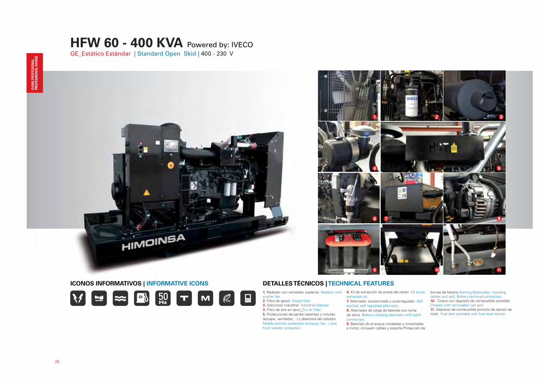
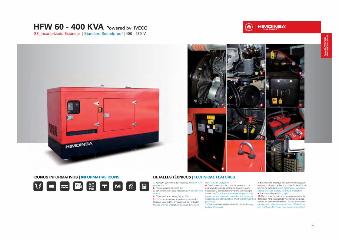
1. Radiador con ventilador soplante. Radiator with pusher fan.2. Filtro de gasoil. Diesel filter.3. Silencioso industrial. Industrial silencer.
4. Filtro de aire en seco_Dry air filter.
5. Protecciones de partes calientes y móviles
(escape, ventilador,...) y delantera del radiador.
Mobile and hot protection (exhaust, fan...) and
front radiator protection.
6. Kit de extracción de aceite del cárter. Oil sump
extraction kit.
7. Alternador, autoexcitado y autorregulado. Self
excited, self regulated alternator.
8. Alternador de carga de baterías con toma
de tierra. Battery charging alternator with earth
connection.9. Batería/s de arranque instaladas y conectadas a motor, incluye/n cables y soporte.Protección de
bornas de batería.Starting Battery/ies, including cables and rack, Battery terminals protection.10. Chasis con depósito de combustible extraible. Chassis with removable fuel tank11. Depósito de combustible provisto de sensor de nivel. Fuel tank provided with fuel level sensor.
DETALLES TÉCNICOS | TECHNICAL FEATURESICONOS INFORMATIVOS | INFORMATIVE ICONS
1
4 5
7
2
6 8
109 11
É
3
26
1. Radiador con ventilador soplante. Radiator with pusher fan.2. Filtro de gasoil. Diesel filter.3. Sensor de nivel agua radiador_Low coolant level sensor.
4. Filtro de aire en seco_Dry air filter.
5. Protecciones de partes calientes y móviles
(escape, ventilador,...) y delantera del radiador.
Mobile and hot protection (exhaust, fan...) and
front radiator protection.6. Cuadro eléctrico de control y potencia, con aparatos de medida central de control (según necesidad y configuración) y protección magne-totérmica.Control and power electric panel, with measurements devices, controller (according to necessity and configuration) and thermal magnetic
protection.7. Desconectador de batería/s (Opcional).Battery isolator (Optional).
8. Batería/s de arranque instaladas y conectadas a motor, incluye/n cables y soporte.Protección de bornas de batería.Starting Battery/ies, including cables and rack, Battery terminals protection.9. Gancho de Izado.Lifting eye.10. Capot insonorizado, con lana de roca de alta densidad. Amplias puertas y controles de agua /aceite, en caso de necesidad. Sound attenuated canopy, with high density rockwool. Wide doors and manholes for water / oil, incase of necessity.
DETALLES TÉCNICOS | TECHNICAL FEATURESICONOS INFORMATIVOS | INFORMATIVE ICONS
1
2 3
4 5
10
7 8
9
HFW 60 - 400 KVA Powered by: IVECOGE_Insonorizado Estándar | Standard Soundproof | 400 - 230 V
6
27
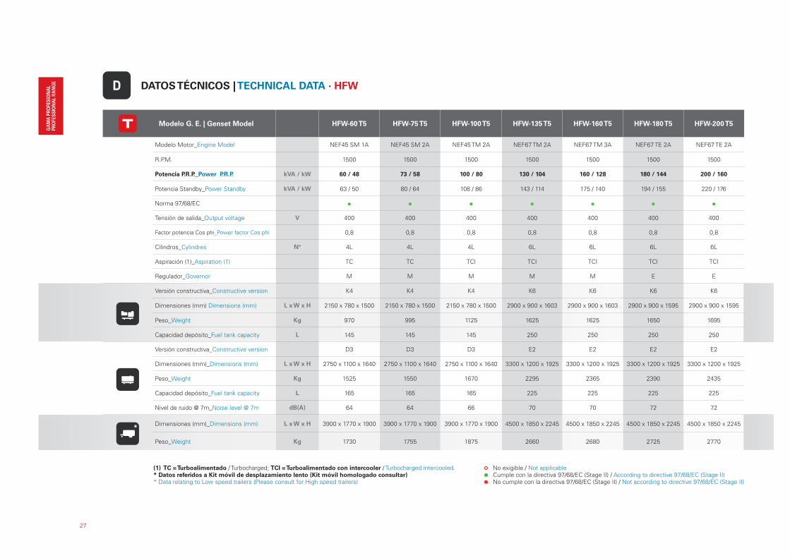
Modelo G. E. | Genset Model HFW-60 T5 HFW-75 T5 HFW-100 T5 HFW-135 T5 HFW-160 T5 HFW-180 T5 HFW-200 T5
Modelo Motor_Engine Model NEF45 SM 1A NEF45 SM 2A NEF45 TM 2A NEF67 TM 2A NEF67 TM 3A NEF67 TE 2A NEF67 TE 2A
R.P.M. 1500 1500 1500 1500 1500 1500 1500
Potencia P.R.P._Power P.R.P. kVA / kW 60 / 48 73 / 58 100 / 80 130 / 104 160 / 128 180 / 144 200 / 160
Potencia Standby_Power Standby kVA / kW 63 / 50 80 / 64 108 / 86 143 / 114 175 / 140 194 / 155 220 / 176
Norma 97/68/EC
Tensión de salida_Output voltage V 400 400 400 400 400 400 400
Factor potencia Cos phi_Power factor Cos phi 0,8 0,8 0,8 0,8 0,8 0,8 0,8
Cilindros_Cylindres Nº 4L 4L 4L 6L 6L 6L 6L
Aspiración (1)_Aspiration (1) TC TC TCI TCI TCI TCI TCI
Regulador_Governor M M M M M E E
Versión constructiva_Constructive version K4 K4 K4 K6 K6 K6 K6
Dimensiones (mm) Dimensions (mm) L x W x H 2150 x 780 x 1500 2150 x 780 x 1500 2150 x 780 x 1500 2900 x 900 x 1603 2900 x 900 x 1603 2900 x 900 x 1595 2900 x 900 x 1595
Peso_Weight Kg 970 995 1125 1625 1625 1650 1695
Capacidad depósito_Fuel tank capacity L 145 145 145 250 250 250 250
Versión constructiva_Constructive version D3 D3 D3 E2 E2 E2 E2
Dimensiones (mm)_Dimensions (mm) L x W x H 2750 x 1100 x 1640 2750 x 1100 x 1640 2750 x 1100 x 1640 3300 x 1200 x 1925 3300 x 1200 x 1925 3300 x 1200 x 1925 3300 x 1200 x 1925
Peso_Weight Kg 1525 1550 1670 2295 2365 2390 2435
Capacidad depósito_Fuel tank capacity L 165 165 165 225 225 225 225
Nivel de ruido @ 7m_Noise level @ 7m dB(A) 64 64 66 70 70 72 72
Dimensiones (mm)_Dimensions (mm) L x W x H 3900 x 1770 x 1900 3900 x 1770 x 1900 3900 x 1770 x 1900 4500 x 1850 x 2245 4500 x 1850 x 2245 4500 x 1850 x 2245 4500 x 1850 x 2245
Peso_Weight Kg 1730 1755 1875 2660 2680 2725 2770
DATOS TÉCNICOS | TECHNICAL DATA · HFWD
No exigible / Not applicable Cumple con la directiva 97/68/EC (Stage II) / According to directive 97/68/EC (Stage II) No cumple con la directiva 97/68/EC (Stage II) / Not according to directive 97/68/EC (Stage II)
(1) TC = Turboalimentado / Turbocharged; TCI = Turboalimentado con intercooler / Turbocharged intercooled.* Datos referidos a Kit móvil de desplazamiento lento (Kit móvil homologado consultar)* Data relating to Low speed trailers (Please consult for High speed trailers)
*
28
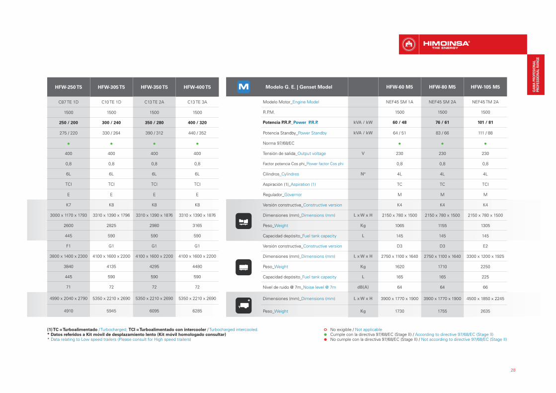
HFW-250 T5 HFW-305 T5 HFW-350 T5 HFW-400 T5
C87 TE 1D C10 TE 1D C13 TE 2A C13 TE 3A
1500 1500 1500 1500
250 / 200 300 / 240 350 / 280 400 / 320
275 / 220 330 / 264 390 / 312 440 / 352
400 400 400 400
0,8 0,8 0,8 0,8
6L 6L 6L 6L
TCI TCI TCI TCI
E E E E
K7 K8 K8 K8
3000 x 1170 x 1793 3310 x 1390 x 1796 3310 x 1390 x 1876 3310 x 1390 x 1876
2600 2825 2980 3165
445 590 590 590
F1 G1 G1 G1
3800 x 1400 x 2300 4100 x 1600 x 2200 4100 x 1600 x 2200 4100 x 1600 x 2200
3840 4135 4295 4480
445 590 590 590
71 72 72 72
4990 x 2040 x 2790 5350 x 2210 x 2690 5350 x 2210 x 2690 5350 x 2210 x 2690
4910 5945 6095 6285
Modelo G. E. | Genset Model HFW-60 M5 HFW-80 M5 HFW-105 M5
Modelo Motor_Engine Model NEF45 SM 1A NEF45 SM 2A NEF45 TM 2A
R.P.M. 1500 1500 1500
Potencia P.R.P._Power P.R.P. kVA / kW 60 / 48 76 / 61 101 / 81
Potencia Standby_Power Standby kVA / kW 64 / 51 83 / 66 111 / 88
Norma 97/68/EC
Tensión de salida_Output voltage V 230 230 230
Factor potencia Cos phi_Power factor Cos phi 0,8 0,8 0,8
Cilindros_Cylindres Nº 4L 4L 4L
Aspiración (1)_Aspiration (1) TC TC TCI
Regulador_Governor M M M
Versión constructiva_Constructive version K4 K4 K4
Dimensiones (mm)_Dimensions (mm) L x W x H 2150 x 780 x 1500 2150 x 780 x 1500 2150 x 780 x 1500
Peso_Weight Kg 1065 1155 1305
Capacidad depósito_Fuel tank capacity L 145 145 145
Versión constructiva_Constructive version D3 D3 E2
Dimensiones (mm)_Dimensions (mm) L x W x H 2750 x 1100 x 1640 2750 x 1100 x 1640 3300 x 1200 x 1925
Peso_Weight Kg 1620 1710 2250
Capacidad depósito_Fuel tank capacity L 165 165 225
Nivel de ruido @ 7m_Noise level @ 7m dB(A) 64 64 66
Dimensiones (mm)_Dimensions (mm) L x W x H 3900 x 1770 x 1900 3900 x 1770 x 1900 4500 x 1850 x 2245
Peso_Weight Kg 1730 1755 2635
No exigible / Not applicable Cumple con la directiva 97/68/EC (Stage II) / According to directive 97/68/EC (Stage II) No cumple con la directiva 97/68/EC (Stage II) / Not according to directive 97/68/EC (Stage II)
(1) TC = Turboalimentado / Turbocharged; TCI = Turboalimentado con intercooler / Turbocharged intercooled.* Datos referidos a Kit móvil de desplazamiento lento (Kit móvil homologado consultar)* Data relating to Low speed trailers (Please consult for High speed trailers)
*
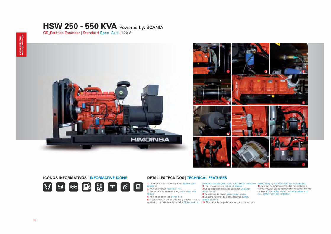
HSW 250 - 550 KVA Powered by: SCANIAGE_Estático Estándar | Standard Open Skid | 400 V
29
1. Radiador con ventilador soplante. Radiator with pusher fan.2. Filtro decantador.Decanting filter.3. Sensor de nivel agua radiador_Low coolant level sensor.
4. Filtro de aire en seco_Dry air filter.
5. Protecciones de partes calientes y móviles (escape,
ventilador,...) y delantera del radiador. Mobile and hot
protection (exhaust, fan...) and front radiator protection.
6. Silencioso industria. Industrial silencer.7. Kit de extracción de aceite del cárter. Oil sump extraction kit.
8. Resistencia de caldeo. Water jacket heater.9. Desconectador de batería/s (opcional).Battery isolator (optional).
10. Alternador de carga de baterías con toma de tierra.
Battery charging alternator with earth connection.11. Batería/s de arranque instaladas y conectadas a motor, incluye/n cables y soporte.Protección de bornas de batería.Starting Battery/ies, including cables and rack, Battery terminals protection.
DETALLES TÉCNICOS | TECHNICAL FEATURESICONOS INFORMATIVOS | INFORMATIVE ICONS
11
2 3
4 5
6 7 8
1
9 10

30
1. Radiador con ventilador soplante. Radiator with pusher fan.2. Filtro decantador.Decanting filter.3. Sensor de nivel agua radiador_Low coolant level sensor.
4. Filtro de aire en seco_Dry air filter.
5. Protecciones de partes calientes y móviles (escape,
ventilador,...) y delantera del radiador. Mobile and hot
protection (exhaust, fan...) and front radiator protection.
6. Kit de extracción de aceite del cárter. Oil sump extraction kit.7. Resistencia de caldeo. Water jacket heater.
8. Desconectador de batería/s. (De serie en toda
la gama HSW con motor SCANIA) Battery isolator.
(Standard in all HSW range with SCANIA engine)9. Tapa Basculante de escape. Exhaust rain cap.10. Chasis predispuesto para posterior instalación de kit
móvil o patín alquilador. (ver modelos y opcional de kits móviles).Chassis ready for later mobile kit installation or rental skid. (see models and mobile kits options)
11. Mecanizado para salida de cables de potencia.
Outlet for power cables.
DETALLES TÉCNICOS | TECHNICAL FEATURESICONOS INFORMATIVOS | INFORMATIVE ICONS
9 10
42
6 7
1
8
3
11
5
HSW 250 - 550 KVA Powered by: SCANIAGE_Insonorizado Estándar | Standard Soundproof | 400 V

31
Modelo G. E. | Genset Model HSW-255 T5 HSW-280 T5 HSW-300 T5 HSW-300 T5 HSW-350 T5 HSW-350 T5
Modelo Motor_Engine Model DC9 65A (10-93) DC9 65A (10-94) DC12 59A (10-31A) DC12 60A (10-17A) DC12 59A (10-32A) DC12 60A (10-18A)
R.P.M. 1500 1500 1500 1500 1500 1500
Potencia P.R.P._Power P.R.P. kVA / kW 250 / 200 281 / 225 300 / 240 300 / 240 350 / 280 350 / 280
Potencia Standby_Power Standby kVA / kW 275 / 220 305 / 244 330 / 264 330 / 264 400 / 320 400 / 320
Norma 97/68/EC
Tensión de salida_Output voltage V 400 400 400 400 400 400
Factor potencia Cos phi_Power factor Cos phi 0,8 0,8 0,8 0,8 0,8 0,8
Cilindros_Cylindres Nº 5L 5L 6L 6L 6L 6L
Aspiración (1)_Aspiration (1) TC TC TCI TCI TCI TCI
Regulador_Governor E E E E E E
Versión constructiva_Constructive version K7 K7 K8 K8 K8 K8
Dimensiones (mm)_Dimensions (mm) L x W x H 3000 x 1160 x 1856 3000 x 1160 x 1856 3310 x 1390 x 1835 3310 x 1390 x 1835 3310 x 1390 x 1835 3310 x 1390 x 1835
Peso_Weight Kg 2080 2440 2730 2730 2810 2810
Capacidad depósito_Fuel tank capacity L 445 445 590 590 590 590
Versión constructiva_Constructive version F1 F1 G1 G1 G1 G1
Dimensiones (mm)_Dimensions (mm) L x W x H 3800 x 1400 x 2300 3800 x 1400 x 2300 4100 x 1600 x 2200 4100 x 1600 x 2200 4100 x 1600 x 2200 4100 x 1600 x 2200
Peso_Weight Kg 3320 3630 4045 4045 4125 4125
Capacidad depósito_Fuel tank capacity L 445 445 590 590 590 590
Nivel de ruido @ 7m_Noise level @ 7m dB(A) 72 72 72 72 72 72
Dimensiones (mm)_Dimensions (mm) L x W x H 5000 x 2210 x 2790 5000 x 2210 x 2790 5250 x 2210 x 2690 5250 x 2210 x 2690 5250 x 2210 x 2690 5250 x 2210 x 2690
Peso_Weight Kg 4390 4705 5850 5850 5930 5930
DATOS TÉCNICOS | TECHNICAL DATA · HSWD
No exigible / Not applicable Cumple con la directiva 97/68/EC (Stage II) / According to directive 97/68/EC (Stage II) No cumple con la directiva 97/68/EC (Stage II) / Not according to directive 97/68/EC (Stage II)
(1) TC = Turboalimentado / Turbocharged; TCI = Turboalimentado con intercooler / Turbocharged intercooled.* Datos referidos a Kit móvil de desplazamiento lento (Kit móvil homologado consultar)* Data relating to Low speed trailers (Please consult for High speed trailers)
*
32
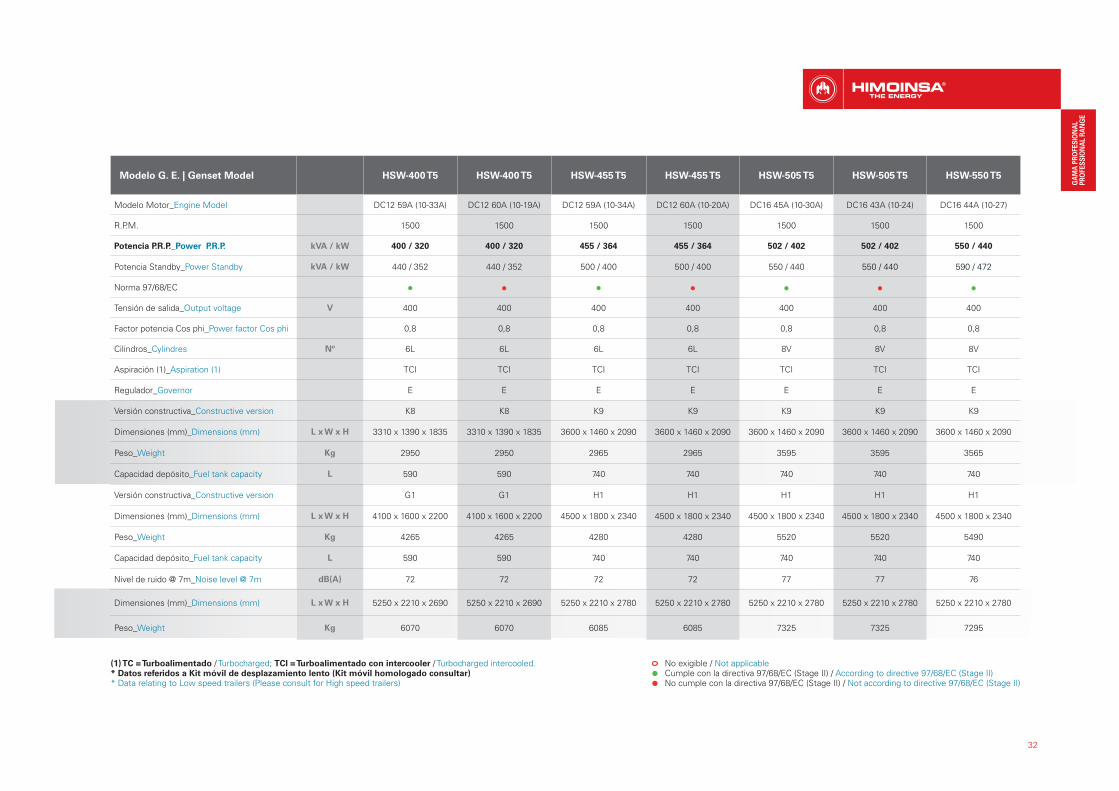
Modelo G. E. | Genset Model HSW-400 T5 HSW-400 T5 HSW-455 T5 HSW-455 T5 HSW-505 T5 HSW-505 T5 HSW-550 T5
Modelo Motor_Engine Model DC12 59A (10-33A) DC12 60A (10-19A) DC12 59A (10-34A) DC12 60A (10-20A) DC16 45A (10-30A) DC16 43A (10-24) DC16 44A (10-27)
R.P.M. 1500 1500 1500 1500 1500 1500 1500
Potencia P.R.P._Power P.R.P. kVA / kW 400 / 320 400 / 320 455 / 364 455 / 364 502 / 402 502 / 402 550 / 440
Potencia Standby_Power Standby kVA / kW 440 / 352 440 / 352 500 / 400 500 / 400 550 / 440 550 / 440 590 / 472
Norma 97/68/EC
Tensión de salida_Output voltage V 400 400 400 400 400 400 400
Factor potencia Cos phi_Power factor Cos phi 0,8 0,8 0,8 0,8 0,8 0,8 0,8
Cilindros_Cylindres Nº 6L 6L 6L 6L 8V 8V 8V
Aspiración (1)_Aspiration (1) TCI TCI TCI TCI TCI TCI TCI
Regulador_Governor E E E E E E E
Versión constructiva_Constructive version K8 K8 K9 K9 K9 K9 K9
Dimensiones (mm)_Dimensions (mm) L x W x H 3310 x 1390 x 1835 3310 x 1390 x 1835 3600 x 1460 x 2090 3600 x 1460 x 2090 3600 x 1460 x 2090 3600 x 1460 x 2090 3600 x 1460 x 2090
Peso_Weight Kg 2950 2950 2965 2965 3595 3595 3565
Capacidad depósito_Fuel tank capacity L 590 590 740 740 740 740 740
Versión constructiva_Constructive version G1 G1 H1 H1 H1 H1 H1
Dimensiones (mm)_Dimensions (mm) L x W x H 4100 x 1600 x 2200 4100 x 1600 x 2200 4500 x 1800 x 2340 4500 x 1800 x 2340 4500 x 1800 x 2340 4500 x 1800 x 2340 4500 x 1800 x 2340
Peso_Weight Kg 4265 4265 4280 4280 5520 5520 5490
Capacidad depósito_Fuel tank capacity L 590 590 740 740 740 740 740
Nivel de ruido @ 7m_Noise level @ 7m dB(A) 72 72 72 72 77 77 76
Dimensiones (mm)_Dimensions (mm) L x W x H 5250 x 2210 x 2690 5250 x 2210 x 2690 5250 x 2210 x 2780 5250 x 2210 x 2780 5250 x 2210 x 2780 5250 x 2210 x 2780 5250 x 2210 x 2780
Peso_Weight Kg 6070 6070 6085 6085 7325 7325 7295
No exigible / Not applicable Cumple con la directiva 97/68/EC (Stage II) / According to directive 97/68/EC (Stage II) No cumple con la directiva 97/68/EC (Stage II) / Not according to directive 97/68/EC (Stage II)
(1) TC = Turboalimentado / Turbocharged; TCI = Turboalimentado con intercooler / Turbocharged intercooled.* Datos referidos a Kit móvil de desplazamiento lento (Kit móvil homologado consultar)* Data relating to Low speed trailers (Please consult for High speed trailers)
HVW 200 - 637 KVA Powered by: VOLVOGE_Estático Estándar | Standard Open Skid | 400 V
33
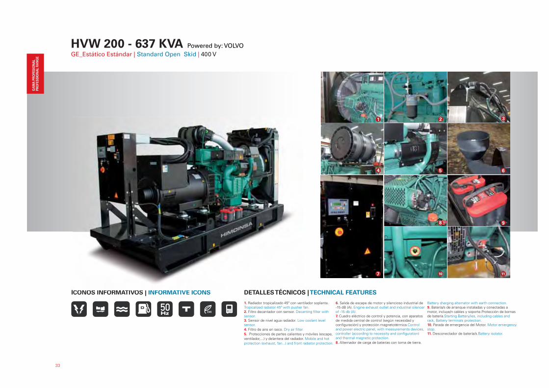
1. Radiador tropicalizado 45º con ventilador soplante.Tropicalized radiator 45º with pusher fan.2. Filtro decantador con sensor. Decanting filter with sensor.3. Sensor de nivel agua radiador. Low coolant level sensor.
4. Filtro de aire en seco. Dry air filter.
5. Protecciones de partes calientes y móviles (escape,
ventilador,...) y delantera del radiador. Mobile and hot
protection (exhaust, fan...) and front radiator protection.
6. Salida de escape de motor y silencioso industrial de -15 dB (A). Engine exhaust outlet and industrial silencer of -15 db (A).7. Cuadro eléctrico de control y potencia, con aparatos de medida central de control (según necesidad y configuración) y protección magnetotérmica.Control and power electric panel, with measurements devices, controller (according to necessity and configuration) and thermal magnetic protection.
8. Alternador de carga de baterías con toma de tierra.
Battery charging alternator with earth connection.9. Batería/s de arranque instaladas y conectadas a motor, incluye/n cables y soporte.Protección de bornas de batería.Starting Battery/ies, including cables and rack, Battery terminals protection.10. Parada de emergencia del Motor. Motor emergency stop.11. Desconectador de batería/s.Battery isolator.
DETALLES TÉCNICOS | TECHNICAL FEATURESICONOS INFORMATIVOS | INFORMATIVE ICONS
21 3
4 5 6
8 9
10 11
É OO O O O | O O
7
HVW 200 - 637 KVA Powered by: VOLVO
GE_Insonorizado Estándar | Standard Soundproof | 400 V
34
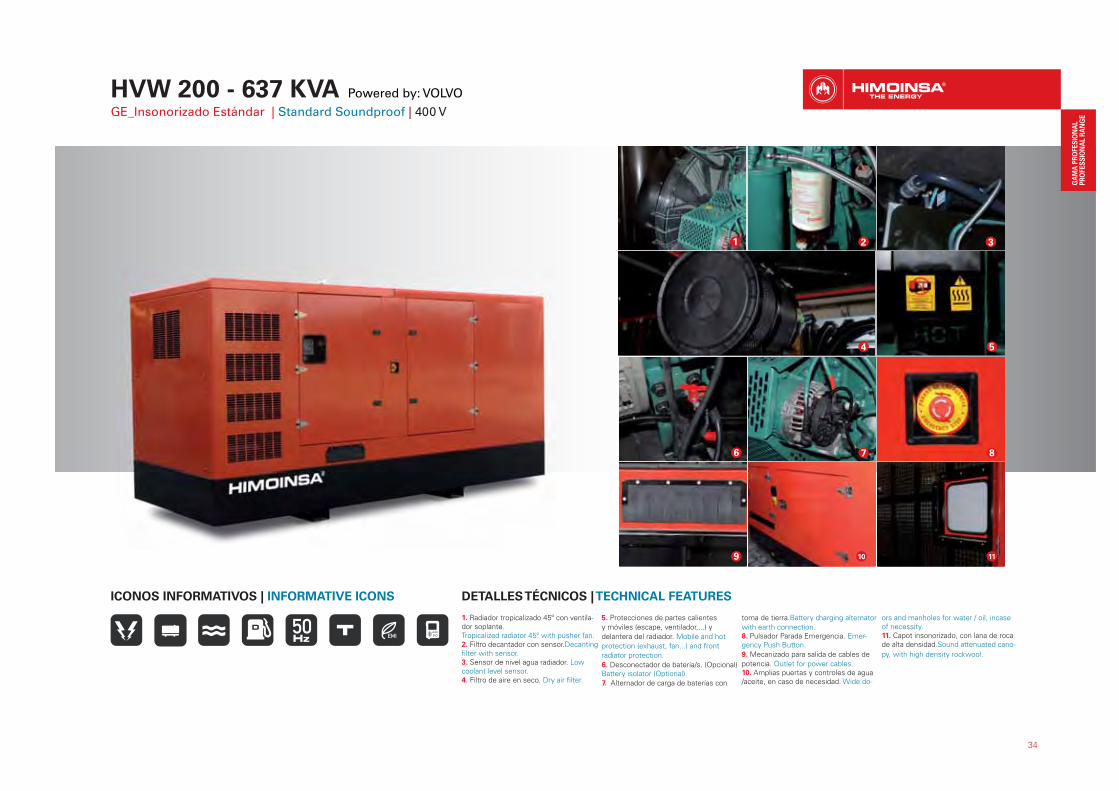
1. Radiador tropicalizado 45º con ventila-dor soplante.Tropicalized radiator 45º with pusher fan.2. Filtro decantador con sensor.Decanting filter with sensor.3. Sensor de nivel agua radiador. Low coolant level sensor.4. Filtro de aire en seco. Dry air filter.
5. Protecciones de partes calientes
y móviles (escape, ventilador,...) y
delantera del radiador. Mobile and hot
protection (exhaust, fan...) and front
radiator protection.
6. Desconectador de batería/s. (Opcional) Battery isolator (Optional).
7. Alternador de carga de baterías con
toma de tierra.Battery charging alternator
with earth connection.8. Pulsador Parada Emergencia. Emer-gency Push Button.
9. Mecanizado para salida de cables de
potencia. Outlet for power cables.10. Amplias puertas y controles de agua /aceite, en caso de necesidad. Wide do-
ors and manholes for water / oil, incase of necessity. 11. Capot insonorizado, con lana de roca de alta densidad.Sound attenuated cano-
py, with high density rockwool.
DETALLES TÉCNICOS | TECHNICAL FEATURESICONOS INFORMATIVOS | INFORMATIVE ICONS
1 32
5
8
4
10
76
9 11
35
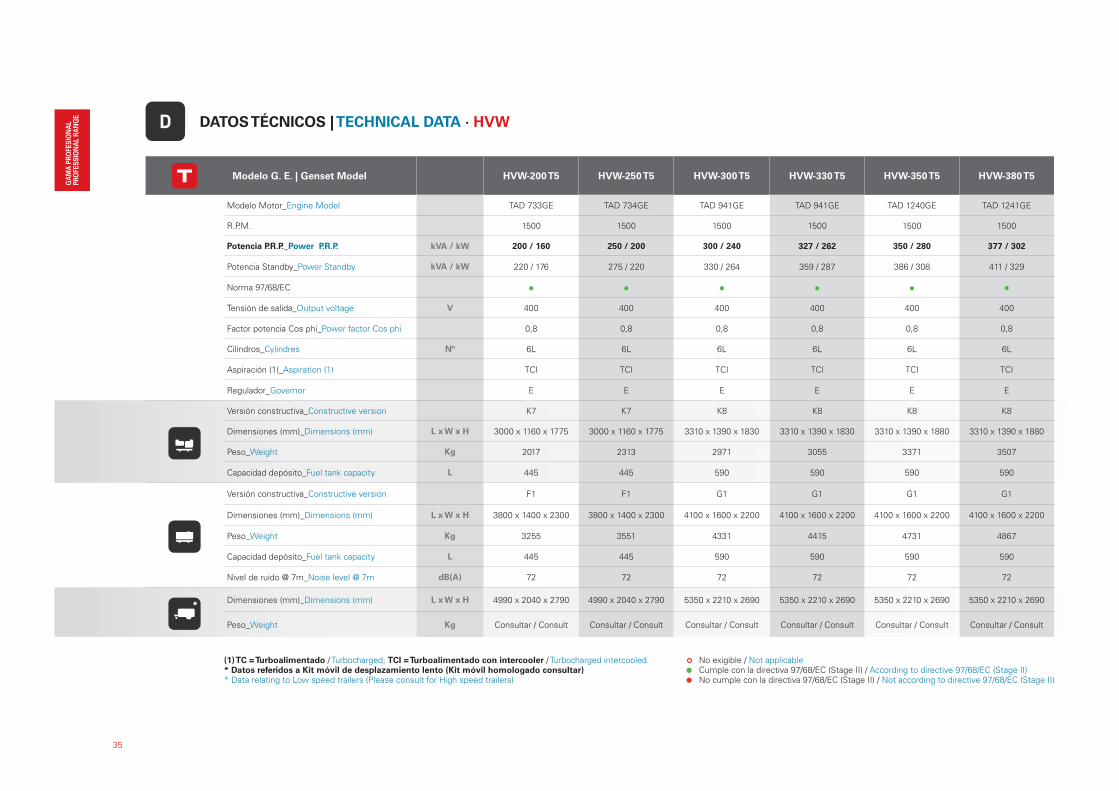
Modelo G. E. | Genset Model HVW-200 T5 HVW-250 T5 HVW-300 T5 HVW-330 T5 HVW-350 T5 HVW-380 T5
Modelo Motor_Engine Model TAD 733GE TAD 734GE TAD 941GE TAD 941GE TAD 1240GE TAD 1241GE
R.P.M. 1500 1500 1500 1500 1500 1500
Potencia P.R.P._Power P.R.P. kVA / kW 200 / 160 250 / 200 300 / 240 327 / 262 350 / 280 377 / 302
Potencia Standby_Power Standby kVA / kW 220 / 176 275 / 220 330 / 264 359 / 287 386 / 308 411 / 329
Norma 97/68/EC
Tensión de salida_Output voltage V 400 400 400 400 400 400
Factor potencia Cos phi_Power factor Cos phi 0,8 0,8 0,8 0,8 0,8 0,8
Cilindros_Cylindres Nº 6L 6L 6L 6L 6L 6L
Aspiración (1)_Aspiration (1) TCI TCI TCI TCI TCI TCI
Regulador_Governor E E E E E E
Versión constructiva_Constructive version K7 K7 K8 K8 K8 K8
Dimensiones (mm)_Dimensions (mm) L x W x H 3000 x 1160 x 1775 3000 x 1160 x 1775 3310 x 1390 x 1830 3310 x 1390 x 1830 3310 x 1390 x 1880 3310 x 1390 x 1880
Peso_Weight Kg 2017 2313 2971 3055 3371 3507
Capacidad depósito_Fuel tank capacity L 445 445 590 590 590 590
Versión constructiva_Constructive version F1 F1 G1 G1 G1 G1
Dimensiones (mm)_Dimensions (mm) L x W x H 3800 x 1400 x 2300 3800 x 1400 x 2300 4100 x 1600 x 2200 4100 x 1600 x 2200 4100 x 1600 x 2200 4100 x 1600 x 2200
Peso_Weight Kg 3255 3551 4331 4415 4731 4867
Capacidad depósito_Fuel tank capacity L 445 445 590 590 590 590
Nivel de ruido @ 7m_Noise level @ 7m dB(A) 72 72 72 72 72 72
Dimensiones (mm)_Dimensions (mm) L x W x H 4990 x 2040 x 2790 4990 x 2040 x 2790 5350 x 2210 x 2690 5350 x 2210 x 2690 5350 x 2210 x 2690 5350 x 2210 x 2690
Peso_Weight Kg Consultar / Consult Consultar / Consult Consultar / Consult Consultar / Consult Consultar / Consult Consultar / Consult
DATOS TÉCNICOS | TECHNICAL DATA · HVWD
No exigible / Not applicable Cumple con la directiva 97/68/EC (Stage II) / According to directive 97/68/EC (Stage II) No cumple con la directiva 97/68/EC (Stage II) / Not according to directive 97/68/EC (Stage II)
(1) TC = Turboalimentado / Turbocharged; TCI = Turboalimentado con intercooler / Turbocharged intercooled.* Datos referidos a Kit móvil de desplazamiento lento (Kit móvil homologado consultar)* Data relating to Low speed trailers (Please consult for High speed trailers)
*
36
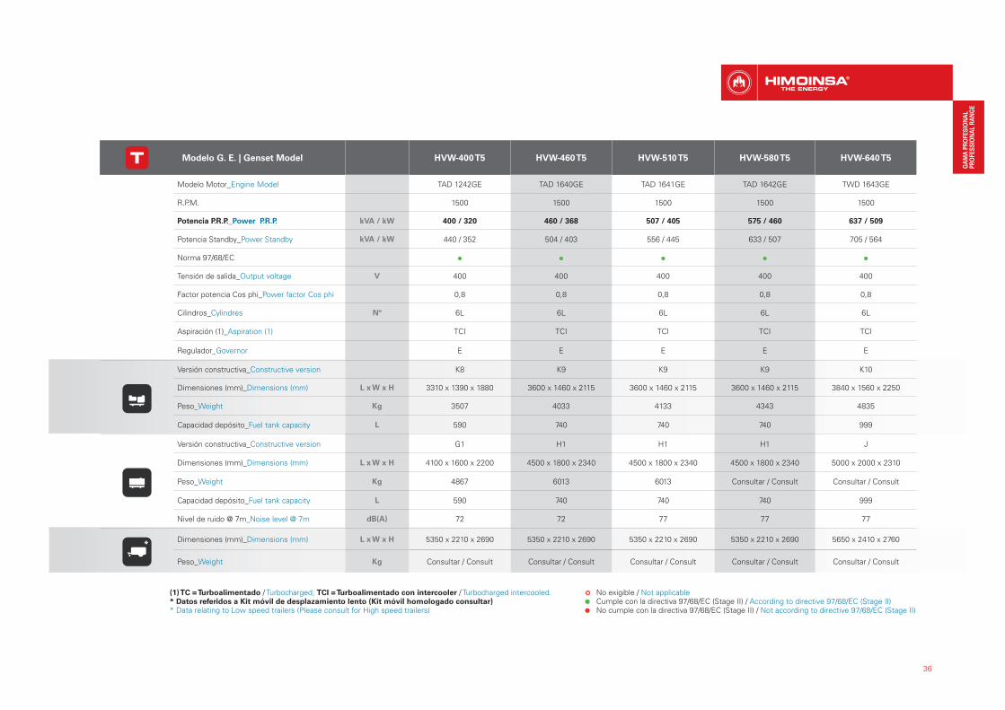
Modelo G. E. | Genset Model HVW-400 T5 HVW-460 T5 HVW-510 T5 HVW-580 T5 HVW-640 T5
Modelo Motor_Engine Model TAD 1242GE TAD 1640GE TAD 1641GE TAD 1642GE TWD 1643GE
R.P.M. 1500 1500 1500 1500 1500
Potencia P.R.P._Power P.R.P. kVA / kW 400 / 320 460 / 368 507 / 405 575 / 460 637 / 509
Potencia Standby_Power Standby kVA / kW 440 / 352 504 / 403 556 / 445 633 / 507 705 / 564
Norma 97/68/EC
Tensión de salida_Output voltage V 400 400 400 400 400
Factor potencia Cos phi_Power factor Cos phi 0,8 0,8 0,8 0,8 0,8
Cilindros_Cylindres Nº 6L 6L 6L 6L 6L
Aspiración (1)_Aspiration (1) TCI TCI TCI TCI TCI
Regulador_Governor E E E E E
Versión constructiva_Constructive version K8 K9 K9 K9 K10
Dimensiones (mm)_Dimensions (mm) L x W x H 3310 x 1390 x 1880 3600 x 1460 x 2115 3600 x 1460 x 2115 3600 x 1460 x 2115 3840 x 1560 x 2250
Peso_Weight Kg 3507 4033 4133 4343 4835
Capacidad depósito_Fuel tank capacity L 590 740 740 740 999
Versión constructiva_Constructive version G1 H1 H1 H1 J
Dimensiones (mm)_Dimensions (mm) L x W x H 4100 x 1600 x 2200 4500 x 1800 x 2340 4500 x 1800 x 2340 4500 x 1800 x 2340 5000 x 2000 x 2310
Peso_Weight Kg 4867 6013 6013 Consultar / Consult Consultar / Consult
Capacidad depósito_Fuel tank capacity L 590 740 740 740 999
Nivel de ruido @ 7m_Noise level @ 7m dB(A) 72 72 77 77 77
Dimensiones (mm)_Dimensions (mm) L x W x H 5350 x 2210 x 2690 5350 x 2210 x 2690 5350 x 2210 x 2690 5350 x 2210 x 2690 5650 x 2410 x 2760
Peso_Weight Kg Consultar / Consult Consultar / Consult Consultar / Consult Consultar / Consult Consultar / Consult
No exigible / Not applicable Cumple con la directiva 97/68/EC (Stage II) / According to directive 97/68/EC (Stage II) No cumple con la directiva 97/68/EC (Stage II) / Not according to directive 97/68/EC (Stage II)
*
(1) TC = Turboalimentado / Turbocharged; TCI = Turboalimentado con intercooler / Turbocharged intercooled.* Datos referidos a Kit móvil de desplazamiento lento (Kit móvil homologado consultar)* Data relating to Low speed trailers (Please consult for High speed trailers)
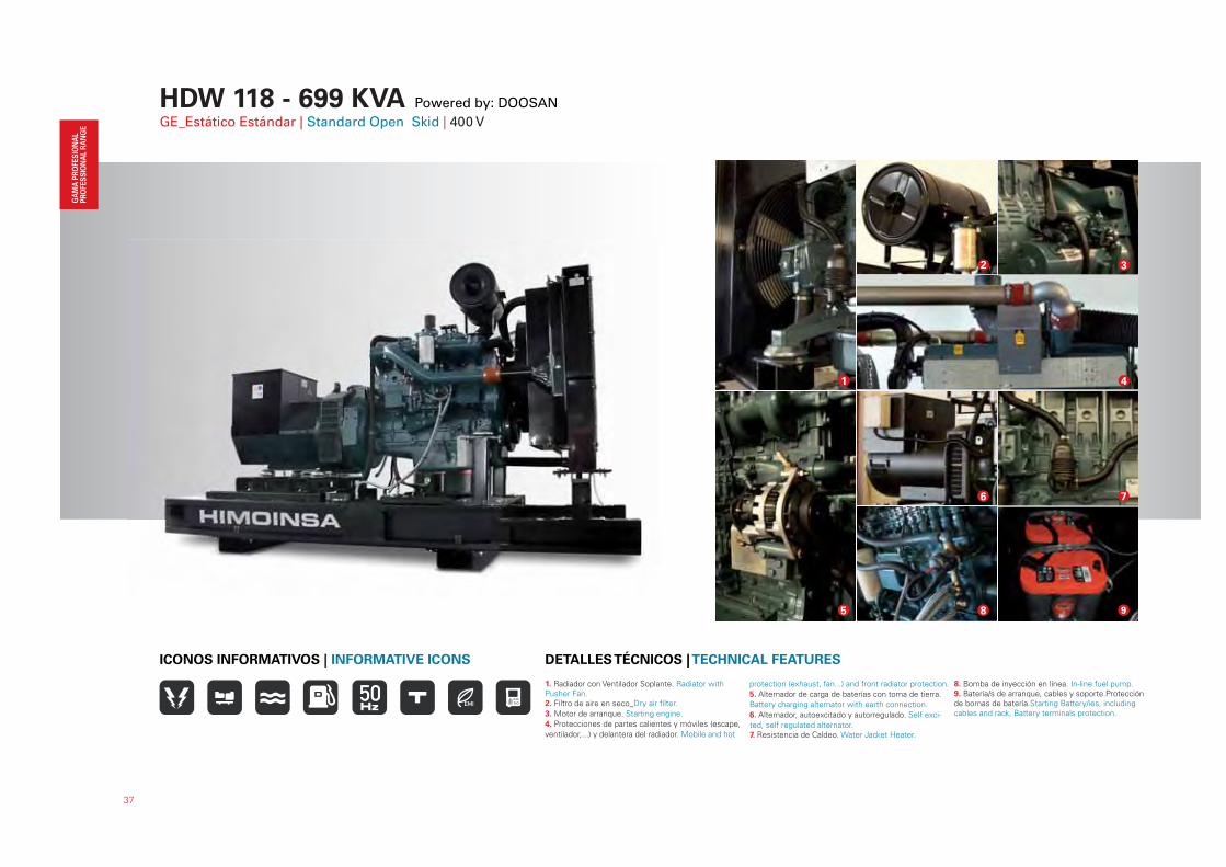
HDW 118 - 699 KVA Powered by: DOOSANGE_Estático Estándar | Standard Open Skid | 400 V
37
1. Radiador con Ventilador Soplante. Radiator with Pusher Fan.2. Filtro de aire en seco_Dry air filter.
3. Motor de arranque. Starting engine.
4. Protecciones de partes calientes y móviles (escape,
ventilador,...) y delantera del radiador. Mobile and hot
protection (exhaust, fan...) and front radiator protection.
5. Alternador de carga de baterías con toma de tierra.
Battery charging alternator with earth connection.
6. Alternador, autoexcitado y autorregulado. Self exci-
ted, self regulated alternator.7. Resistencia de Caldeo. Water Jacket Heater.
8. Bomba de inyección en línea. In-line fuel pump.9. Batería/s de arranque, cables y soporte.Protección de bornas de batería.Starting Battery/ies, including cables and rack, Battery terminals protection.
DETALLES TÉCNICOS | TECHNICAL FEATURESICONOS INFORMATIVOS | INFORMATIVE ICONS
1
2
7
4
3
9
6
85
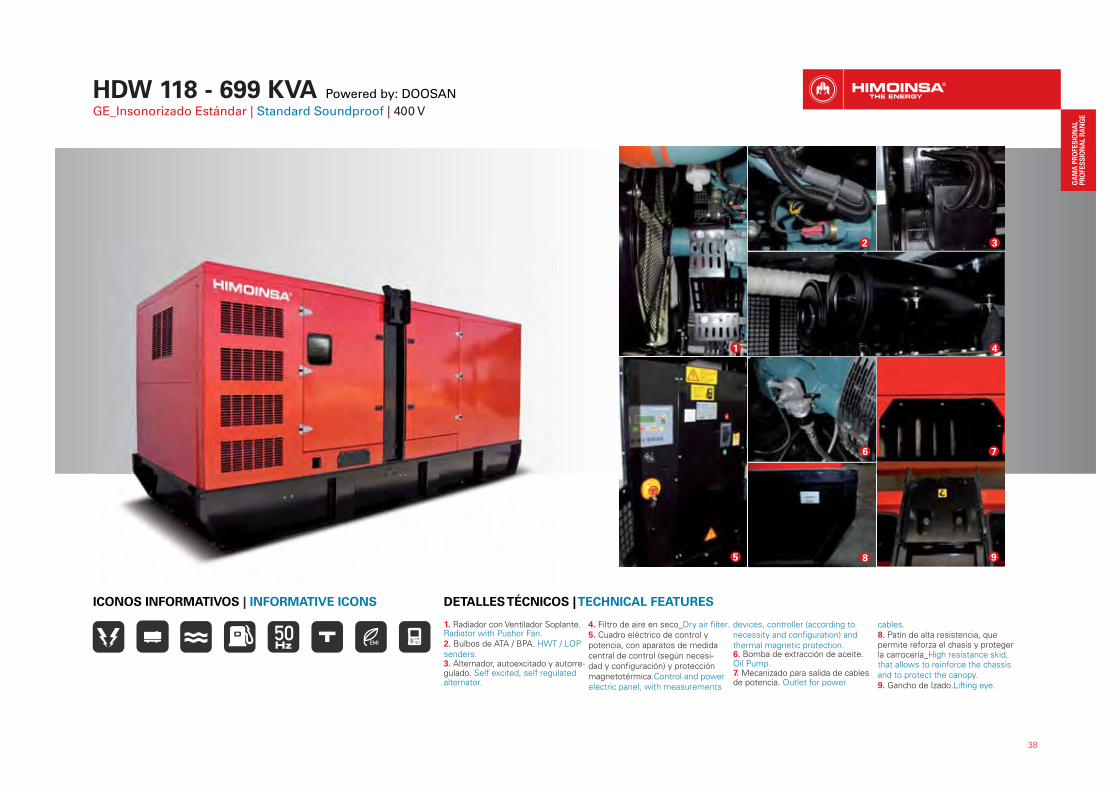
HDW 118 - 699 KVA Powered by: DOOSANGE_Insonorizado Estándar | Standard Soundproof | 400 V
38
1. Radiador con Ventilador Soplante. Radiator with Pusher Fan.2. Bulbos de ATA / BPA. HWT / LOP senders.3. Alternador, autoexcitado y autorre-gulado. Self excited, self regulated alternator.
4. Filtro de aire en seco_Dry air filter.5. Cuadro eléctrico de control y potencia, con aparatos de medida central de control (según necesi-dad y configuración) y protección magnetotérmica.Control and power electric panel, with measurements
devices, controller (according to necessity and configuration) and thermal magnetic protection.6. Bomba de extracción de aceite. Oil Pump.7. Mecanizado para salida de cables de potencia. Outlet for power
cables.8. Patín de alta resistencia, que permite reforza el chasis y proteger la carrocería_High resistance skid, that allows to reinforce the chassis and to protect the canopy.9. Gancho de Izado.Lifting eye.
DETALLES TÉCNICOS | TECHNICAL FEATURESICONOS INFORMATIVOS | INFORMATIVE ICONS
8 9
7
1
2
4
6
5
3
39
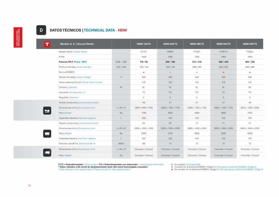
Modelo G. E. | Genset Model HDW-120 T5 HDW-200 T5 HDW-285 T5 HDW-300 T5 HDW-400 T5
Modelo Motor_Engine Model D114T P086TI P126TI P126TI-II P158LE
R.P.M. 1500 1500 1500 1500 1500
Potencia P.R.P._Power P.R.P. kVA / kW 118 / 95 200 / 160 272 / 210 300 / 240 400 / 320
Potencia Standby_Power Standby kVA / kW 130 / 104 220 / 176 306 / 245 330 / 264 450 / 360
Norma 97/68/EC
Tensión de salida_Output voltage V 400 400 400 400 400
Factor potencia Cos phi_Power factor Cos phi 0,8 0,8 0,8 0,8 0,8
Cilindros_Cylindres Nº 6L 6L 6L 6L 8V
Aspiración (1)_Aspiration (1) TC TCI TCI TCI TCI
Regulador_Governor E E E E E
Versión constructiva_Constructive version K6 K7 K7 K7 K9
Dimensiones (mm)_Dimensions (mm) L x W x H 2900 x 900 x 1610 3000 x 1160 x 1725 3000 x 1160 x 1725 3000 x 1160 x 1725 3610 x 1460 x 2020
Peso_Weight Kg 1750 2000 2500 2650 3100
Capacidad depósito_Fuel tank capacity L 250 445 445 445 740
Versión constructiva_Constructive version E2 E2 F1 F1 H1
Dimensiones (mm)_Dimensions (mm) L x W x H 3300 x 1200 x 1925 3300 x 1200 x 2300 3800 x 1400 x 2300 3800 x 1400 x 2300 4500 x 1800 x 2200
Peso_Weight Kg 2500 3150 3650 4200 5350
Capacidad depósito_Fuel tank capacity L 225 225 445 445 740
Nivel de ruido @ 7m_Noise level @ 7m dB(A) 68 72 72 72 72
Dimensiones (mm)_Dimensions (mm) L x W x H Consultar / Consult Consultar / Consult Consultar / Consult Consultar / Consult Consultar / Consult
Peso_Weight Kg Consultar / Consult Consultar / Consult Consultar / Consult Consultar / Consult Consultar / Consult
DATOS TÉCNICOS | TECHNICAL DATA · HDWD
No exigible / Not applicable Cumple con la directiva 97/68/EC (Stage II) / According to directive 97/68/EC (Stage II) No cumple con la directiva 97/68/EC (Stage II) / Not according to directive 97/68/EC (Stage II)
(1) TC = Turboalimentado / Turbocharged; TCI = Turboalimentado con intercooler / Turbocharged intercooled.* Datos referidos a Kit móvil de desplazamiento lento (Kit móvil homologado consultar)* Data relating to Low speed trailers (Please consult for High speed trailers)
*
40
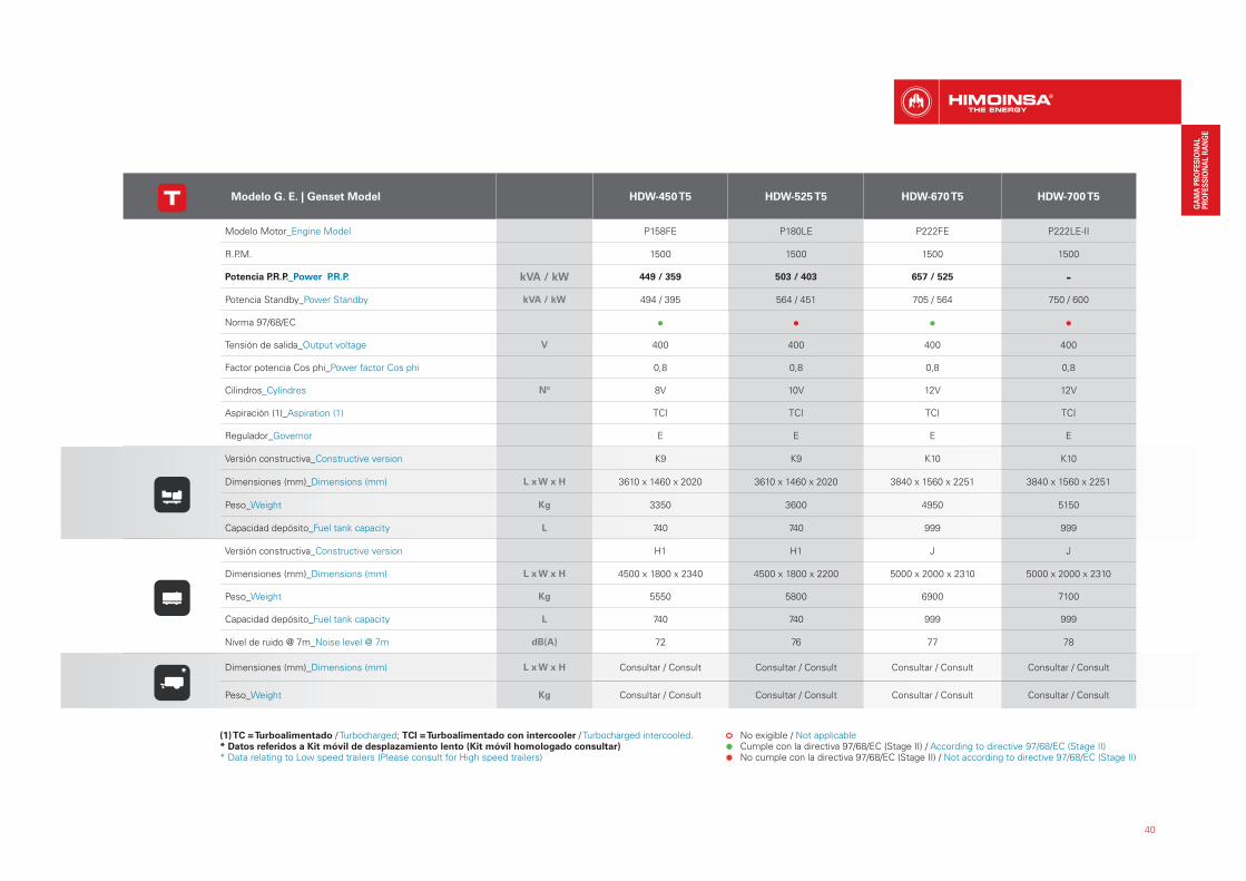
Modelo G. E. | Genset Model HDW-450 T5 HDW-525 T5 HDW-670 T5 HDW-700 T5
Modelo Motor_Engine Model P158FE P180LE P222FE P222LE-II
R.P.M. 1500 1500 1500 1500
Potencia P.R.P._Power P.R.P. kVA / kW 449 / 359 503 / 403 657 / 525 -
Potencia Standby_Power Standby kVA / kW 494 / 395 564 / 451 705 / 564 750 / 600
Norma 97/68/EC
Tensión de salida_Output voltage V 400 400 400 400
Factor potencia Cos phi_Power factor Cos phi 0,8 0,8 0,8 0,8
Cilindros_Cylindres Nº 8V 10V 12V 12V
Aspiración (1)_Aspiration (1) TCI TCI TCI TCI
Regulador_Governor E E E E
Versión constructiva_Constructive version K9 K9 K10 K10
Dimensiones (mm)_Dimensions (mm) L x W x H 3610 x 1460 x 2020 3610 x 1460 x 2020 3840 x 1560 x 2251 3840 x 1560 x 2251
Peso_Weight Kg 3350 3600 4950 5150
Capacidad depósito_Fuel tank capacity L 740 740 999 999
Versión constructiva_Constructive version H1 H1 J J
Dimensiones (mm)_Dimensions (mm) L x W x H 4500 x 1800 x 2340 4500 x 1800 x 2200 5000 x 2000 x 2310 5000 x 2000 x 2310
Peso_Weight Kg 5550 5800 6900 7100
Capacidad depósito_Fuel tank capacity L 740 740 999 999
Nivel de ruido @ 7m_Noise level @ 7m dB(A) 72 76 77 78
Dimensiones (mm)_Dimensions (mm) L x W x H Consultar / Consult Consultar / Consult Consultar / Consult Consultar / Consult
Peso_Weight Kg Consultar / Consult Consultar / Consult Consultar / Consult Consultar / Consult
No exigible / Not applicable Cumple con la directiva 97/68/EC (Stage II) / According to directive 97/68/EC (Stage II) No cumple con la directiva 97/68/EC (Stage II) / Not according to directive 97/68/EC (Stage II)
(1) TC = Turboalimentado / Turbocharged; TCI = Turboalimentado con intercooler / Turbocharged intercooled.* Datos referidos a Kit móvil de desplazamiento lento (Kit móvil homologado consultar)* Data relating to Low speed trailers (Please consult for High speed trailers)
*

HLA 9,9 - 15,1 KVA Powered by: LOMBARDINIGE_Estático Estándar | Standard Open Skid | 400 - 230 V
41
1. Protector de correa de ditribución. Timing belt cover.2. Protecciones del escape. Exhaust guards.3. Salida de escape de motor y silencioso industrial de -15 dB (A). Engine exhaust outlet and industrial silencer of -15 db (A).
4. Filtro de aire en seco. Dry ail filter.
5. Alternador, autoexcitado y autorregulado. Self exci-
ted, self regulated alternator.
6. Filtro de Gasoil. Diesel Filter.
7. Cuadro eléctrico de control y potencia, con aparatos de medida central de control (según necesidad y configuración) y protección magnetotérmica.Control and power electric panel, with measurements devices, controller (according to necessity and configuration) and thermal magnetic protection.8. Pulsador Parada de Emergencia. Emergency Stop Button.9. Batería/s de arranque instaladas y conectadas a
motor, incluye/n cables y soporte.Protección de bornas de batería.Starting Battery/ies, including cables and rack, Battery terminals protection.10. Chasis con depósito de combustible extraible e integrado y provisto de aforador. Chassis with remo-vable and integrated fuel tank and provided with fuel level sender.
DETALLES TÉCNICOS | TECHNICAL FEATURESICONOS INFORMATIVOS | INFORMATIVE ICONS
7
11
1
3
6
10
7 8
9
2
DETALLES INFORMATIVOS | INFORMATIVE ICONS
54

Modelo G. E. | Genset Model HLA1-10 T5 HLA1-16 T5
Modelo Motor Engine Model
9LD 625/2 11LD626-3
R.P.M. 1500 1500
Potencia P.R.P.
Power P.R.P. kVA / kW 9,9 / 7,9 15,1 / 12,1
Potencia StandbyPower Standby
kVA / kW 11,4 / 9,1 17 / 13,6
Norma 97/68/EC
Tensión de salidaOutput voltage
V 400 400
Factor potencia Cos phiPower factor Cos phi
0,8 0,8
CilindrosCylindres
Nº 2L 3L
Aspiración (1)Aspiration (1)
NA NA
Versión constructivaConstructive version
K0 K0
Dimensiones (mm) Dimensions (mm)
L x W x H 1285 x 690 x 1080 1285 x 690 x 1080
PesoWeight
Kg 280 310
Capacidad depósitoFuel tank capacity
L 35 35
42
Modelo G. E. | Genset Model HLA1-8 M5 HLA1-13 M5
Modelo Motor Engine Model
9LD 625/2 11LD626-3
R.P.M. 1500 1500
Potencia P.R.P.
Power P.R.P. kVA / kW 7,9 / 7,9 12,1 / 12,1
Potencia StandbyPower Standby
kVA / kW 8,5 / 8,5 13,7 / 13,7
Norma 97/68/EC
Tensión de salidaOutput voltage
V 230 230
Factor potencia Cos phiPower factor Cos phi
1 1
CilindrosCylindres
Nº 2L 3L
Aspiración (1)Aspiration (1)
NA NA
Versión constructivaConstructive version
K0 K0
Dimensiones (mm) Dimensions (mm)
L x W x H 1285 x 690 x 1080 1285 x 690 x 1080
PesoWeight
Kg 290 335
Capacidad depósitoFuel tank capacity
L 35 35
DATOS TÉCNICOS | TECHNICAL DATA · HLAD
(1) NA = Aspiración Natural / Natural Aspirated No exigible / Not applicable Cumple con la directiva 97/68/EC (Stage II) / According to directive 97/68/EC (Stage II) No cumple con la directiva 97/68/EC (Stage II) / Not according to directive 97/68/EC (Stage II)
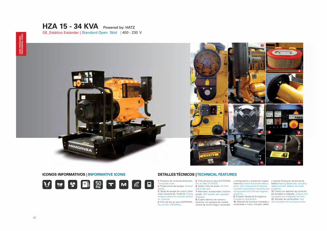
HZA 15 - 34 KVA Powered by: HATZ GE_Estático Estándar | Standard Open Skid | 400 - 230 V
43
1. Protector de correa de ditribución. Timing belt cover.2. Protecciones del escape. Exhaust guards.3. Salida de escape de motor y silen-cioso industrial de -15 dB (A). Engine exhaust outlet and industrial silencer
of -15 db (A).
4. Filtro de aire en seco (INTERIOR).
Dry air filter (INTERNAL).
5. Filtro de aire en seco (EXTERIOR). Dry air filter (OUTSIDE).6. Varilla y filtro de aceite. Oil filter and oil dip stick.
7. Alternador, autoexcitado y autorre-
gulado. Self excited, self regulated
alternator.8. Cuadro eléctrico de control y potencia, con aparatos de medida central de control (según necesidad
y configuración) y protección magne-totérmica.Control and power electric panel, with measurements devices, controller (according to necessity and configuration) and thermal magnetic protection.9. Pulsador Parada de Emergencia. Emergency Stop Button.10. Batería/s de arranque instaladas y conectadas a motor, incluye/n cables
y soporte.Protección de bornas de batería.Starting Battery/ies, including cables and rack, Battery terminals protection.11. Chasis con depósito de combusti-ble extraible e integrado. Chassis with removable and integrated fuel tank.12. Aforador de combustible. Fuel tank provided with fuel level sender.
DETALLES TÉCNICOS | TECHNICAL FEATURESICONOS INFORMATIVOS | INFORMATIVE ICONS
1
2
3
4
6
5
98
12
7
10 11
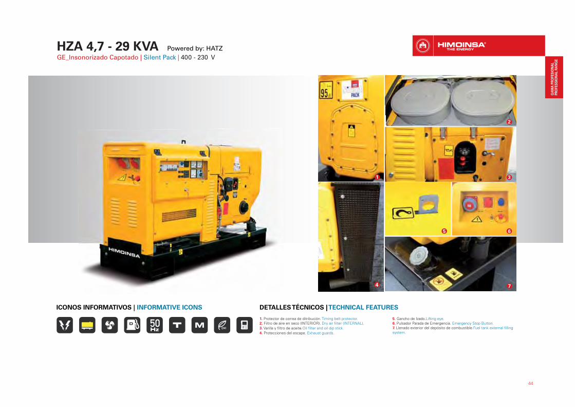
HZA 4,7 - 29 KVA Powered by: HATZ GE_Insonorizado Capotado | Silent Pack | 400 - 230 V
44
1. Protector de correa de ditribución. Timing belt protector.2. Filtro de aire en seco (INTERIOR). Dry air filter (INTERNAL).
3. Varilla y filtro de aceite.Oil filter and oil dip stick.
4. Protecciones del escape. Exhaust guards.
5. Gancho de Izado.Lifting eye.6. Pulsador Parada de Emergencia. Emergency Stop Button.7. Llenado exterior del depósito de combustible.Fuel tank external filling system.
DETALLES TÉCNICOS | TECHNICAL FEATURESICONOS INFORMATIVOS | INFORMATIVE ICONS
1
4
2
3
7
5 6
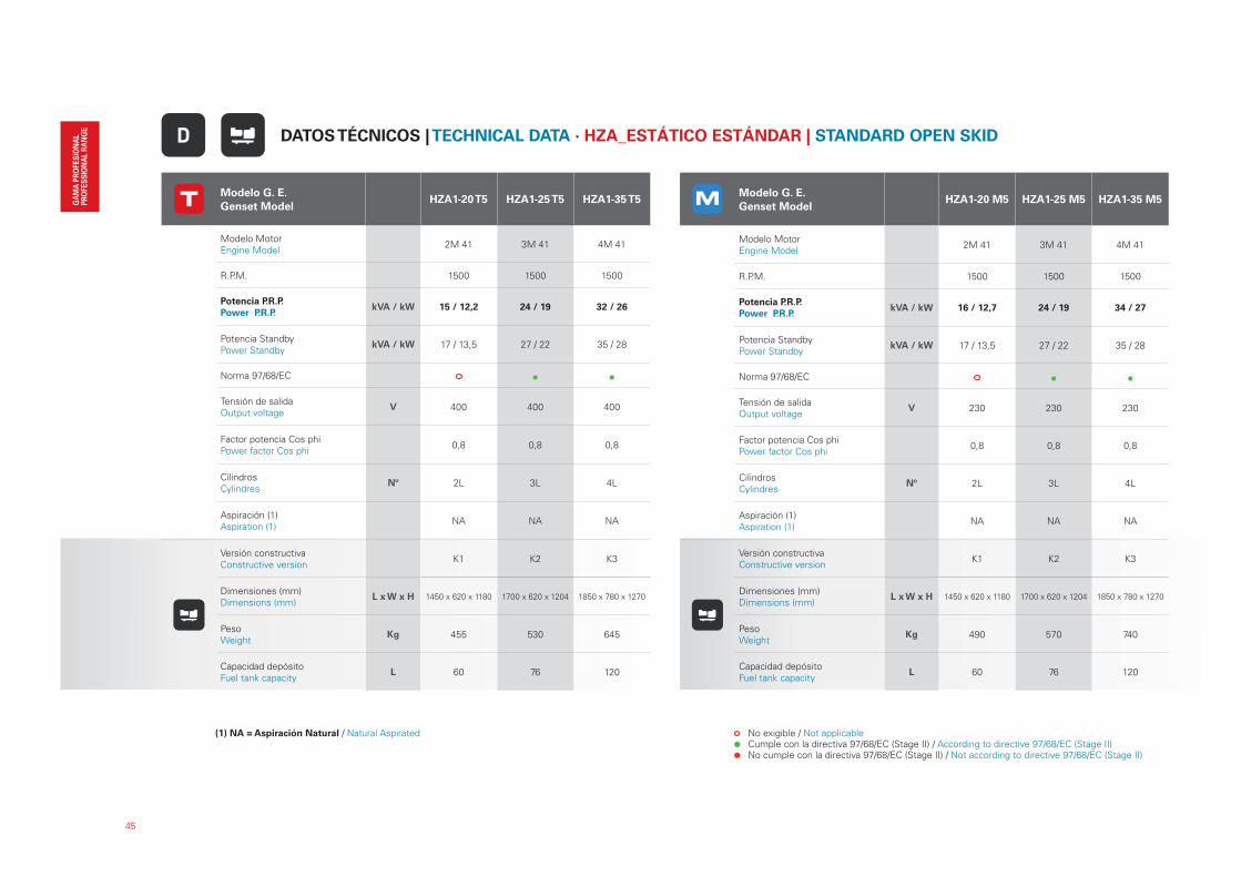
(1) NA = Aspiración Natural / Natural Aspirated
45
Modelo G. E.
Genset ModelHZA1-20 T5 HZA1-25 T5 HZA1-35 T5
Modelo Motor Engine Model
2M 41 3M 41 4M 41
R.P.M. 1500 1500 1500
Potencia P.R.P.
Power P.R.P. kVA / kW 15 / 12,2 24 / 19 32 / 26
Potencia StandbyPower Standby
kVA / kW 17 / 13,5 27 / 22 35 / 28
Norma 97/68/EC
Tensión de salidaOutput voltage
V 400 400 400
Factor potencia Cos phiPower factor Cos phi
0,8 0,8 0,8
CilindrosCylindres
Nº 2L 3L 4L
Aspiración (1)Aspiration (1)
NA NA NA
Versión constructivaConstructive version
K1 K2 K3
Dimensiones (mm) Dimensions (mm)
L x W x H 1450 x 620 x 1180 1700 x 620 x 1204 1850 x 780 x 1270
PesoWeight
Kg 455 530 645
Capacidad depósitoFuel tank capacity
L 60 76 120
Modelo G. E.
Genset ModelHZA1-20 M5 HZA1-25 M5 HZA1-35 M5
Modelo Motor Engine Model
2M 41 3M 41 4M 41
R.P.M. 1500 1500 1500
Potencia P.R.P.
Power P.R.P. kVA / kW 16 / 12,7 24 / 19 34 / 27
Potencia StandbyPower Standby
kVA / kW 17 / 13,5 27 / 22 35 / 28
Norma 97/68/EC
Tensión de salidaOutput voltage
V 230 230 230
Factor potencia Cos phiPower factor Cos phi
0,8 0,8 0,8
CilindrosCylindres
Nº 2L 3L 4L
Aspiración (1)Aspiration (1)
NA NA NA
Versión constructivaConstructive version
K1 K2 K3
Dimensiones (mm) Dimensions (mm)
L x W x H 1450 x 620 x 1180 1700 x 620 x 1204 1850 x 780 x 1270
PesoWeight
Kg 490 570 740
Capacidad depósitoFuel tank capacity
L 60 76 120
DATOS TÉCNICOS | TECHNICAL DATA · HZA_ESTÁTICO ESTÁNDAR | STANDARD OPEN SKIDD
No exigible / Not applicable Cumple con la directiva 97/68/EC (Stage II) / According to directive 97/68/EC (Stage II) No cumple con la directiva 97/68/EC (Stage II) / Not according to directive 97/68/EC (Stage II)
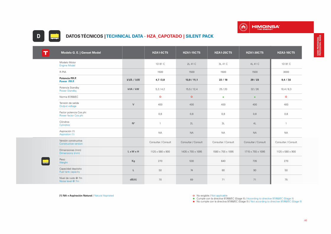
46
Modelo G. E. | Genset Model HZA1-5C T5 HZA1-15C T5 HZA1-25C T5 HZA1-30C T5 HZA3-10C T5
Modelo Motor Engine Model
1D 81 C 2L 41 C 3L 41 C 4L 41 C 1D 81 C
R.P.M. 1500 1500 1500 1500 3000
Potencia P.R.P.
Power P.R.P. kVA / kW 4,7 /3,8 13,9 / 11,1 22 / 18 29 / 23 9,4 / 7,6
Potencia StandbyPower Standby
kVA / kW 5,2 / 4,2 15,5 / 12,4 25 / 20 32 / 26 10,4 / 8,3
Norma 97/68/EC
Tensión de salidaOutput voltage
V 400 400 400 400 400
Factor potencia Cos phiPower factor Cos phi
0,8 0,8 0,8 0,8 0,8
CilindrosCylindres
Nº 1 2L 3L 4L 1
Aspiración (1)Aspiration (1)
NA NA NA NA NA
Versión constructivaConstructive version
Consultar / Consult Consultar / Consult Consultar / Consult Consultar / Consult Consultar / Consult
Dimensiones (mm) Dimensions (mm)
L x W x H 1125 x 580 x 900 1435 x 755 x 1095 1580 x 755 x 1095 1715 x 755 x 1095 1125 x 580 x 900
PesoWeight
Kg 270 530 640 735 270
Capacidad depósitoFuel tank capacity
L 50 74 80 90 50
Nivel de ruido @ 7mNoise level @ 7m
dB(A) 70 69 71 71 75
No exigible / Not applicable Cumple con la directiva 97/68/EC (Stage II) / According to directive 97/68/EC (Stage II) No cumple con la directiva 97/68/EC (Stage II) / Not according to directive 97/68/EC (Stage II)
(1) NA = Aspiración Natural / Natural Aspirated
DATOS TÉCNICOS | TECHNICAL DATA · HZA_CAPOTADO | SILENT PACKD

47
Modelo G. E. | Genset Model HZA1-4C M5 HZA1-15C M5 HZA1-20C M5 HZA3-8C M5
Modelo Motor Engine Model
1D 81 C 2L 41 C 3L 41 C 1D 81 C
R.P.M. 1500 1500 1500 3000
Potencia P.R.P.
Power P.R.P. kVA / kW 3,8 / 3,8 14,5 / 11,6 19 / 15 7,4 / 7,4
Potencia StandbyPower Standby
kVA / kW 4,2 / 4,2 16 / 12,8 21 / 16,9 8,1 / 8,1
Norma 97/68/EC
Tensión de salidaOutput voltage
V 230 230 230 230
Factor potencia Cos phiPower factor Cos phi
1 0,8 0,8 1
CilindrosCylindres
Nº 1 2L 3L 1
Aspiración (1)Aspiration (1)
NA NA NA NA
Versión constructivaConstructive version
Consultar / Consult Consultar / Consult Consultar / Consult Consultar / Consult
Dimensiones (mm) Dimensions (mm)
L x W x H 1125 x 580 x 900 1435 x 755 x 1095 1580 x 755 x 1095 1125 x 580 x 900
PesoWeight
Kg 265 530 640 265
Capacidad depósitoFuel tank capacity
L 50 74 80 50
Nivel de ruido @ 7mNoise level @ 7m
dB(A) 70 69 72 75
DATOS TÉCNICOS | TECHNICAL DATA · HZA_CAPOTADO | SILENT PACKD
No exigible / Not applicable Cumple con la directiva 97/68/EC (Stage II) / According to directive 97/68/EC (Stage II) No cumple con la directiva 97/68/EC (Stage II) / Not according to directive 97/68/EC (Stage II)
(1) NA = Aspiración Natural / Natural Aspirated
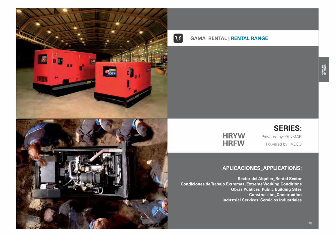
52
APLICACIONES_APPLICATIONS:
Sector del Alquiler_Rental Sector
Condiciones de Trabajo Extremas_Extreme Working Conditions
Obras Públicas_Public Building Sites
Construcción_Construction
Industrial Services_Servicios Industriales
48
GAMA RENTAL | RENTAL RANGE
SERIES: Powered by: YANMAR
Powered by: IVECO
HRYWHRFW

HR 20 - 200 KVA Powered by: YANMAR & FPT (IVECO)ALCANCE DE SUMINISTRO | SCOPE OF SUPPLY · GE_Insonorizado Estándar | Standard Soundproof| 400 V
1. Doble protección por parada de emer-gencia conmutada. Double protection for emergency stop commuted.2. Filtro de comubstible con decantador.Decanting fuel filter.3. Bomba de extracción de aceite. Oil
extraction pump.
4. Iman permanente. Permanent magnet.
5. Registros para limpieza del chasis.Drain valve for easy chassis cleaning.6. Llenado exterior del depósito de com-bustible, con llave de seguridad.Fuel tank external filling system (lockable filler cap).7. Gancho de Izado.Lifting eye.8. Desconectador de batería/s.Battery isolator.
9. Registro para limpieza y drenaje del depósito de combustible. Easy access for cleaning and fast draining fuel tank.10. Pre-instalación o nicho, para albergar los enchufes de conexión rápidos para trasiego del combustible.Nest for quick release couplings (external fuel supply).11. Kit valvula de tres vías y enchufes de co-
nexión rápidos para trasiego de combustible. 3 way valve kit and quick release couptings for fuel decanting.12. Patín de arrastre implementado en chasis anti-fugas, con tubo que facilita el arrastre por cadenas.Sledging skid embedded in leak proof chassis, with bar for pulling with chains.
DETALLES TÉCNICOS | TECHNICAL FEATURES
1 2 3
4 5 6
7 8 9
10 11 12
49
ICONOS INFORMATIVOS | INFORMATIVE ICONS
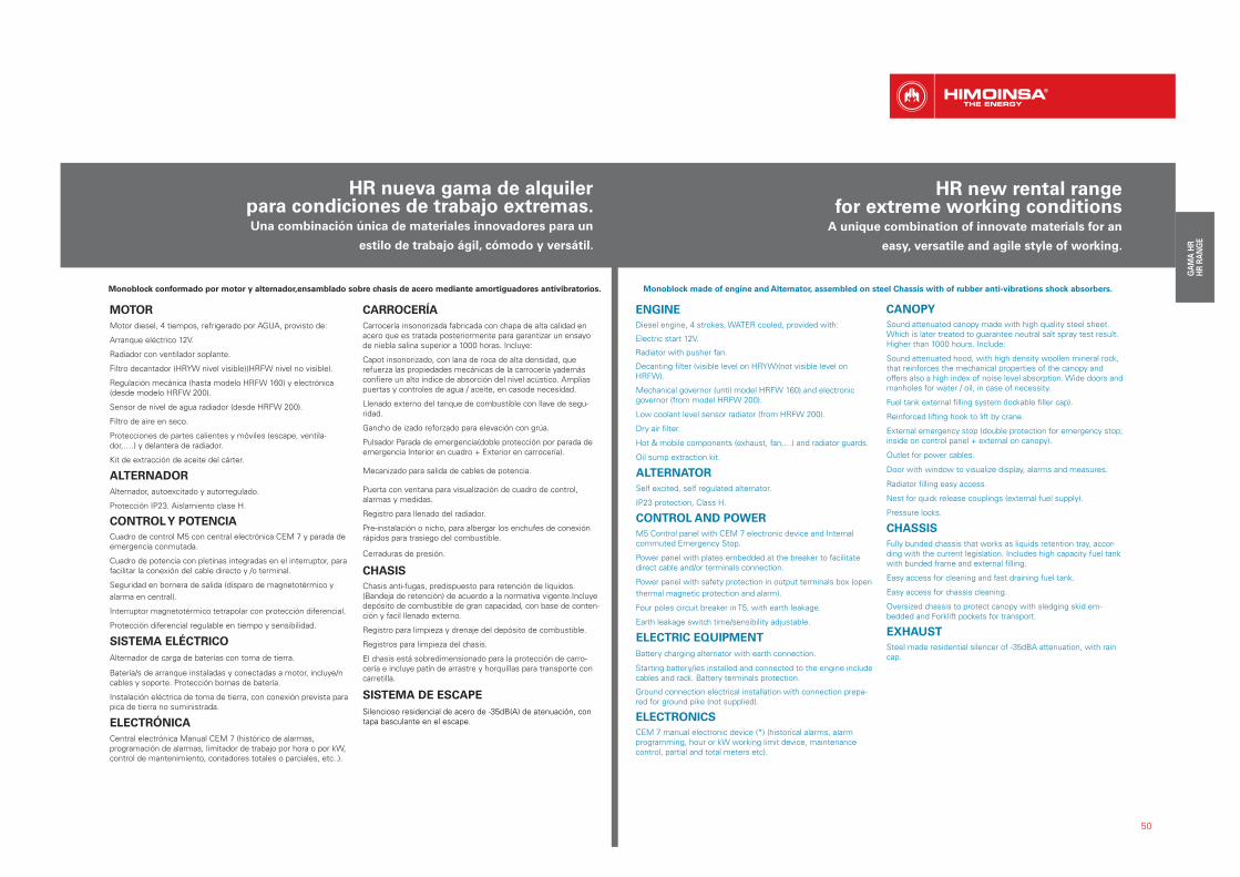
Monoblock conformado por motor y alternador,ensamblado sobre chasis de acero mediante amortiguadores antivibratorios.
MOTOR
Motor diesel, 4 tiempos, refrigerado por AGUA, provisto de:
Arranque eléctrico 12V.
Radiador con ventilador soplante.
Filtro decantador (HRYW nivel visible)(HRFW nivel no visible).
Regulación mecánica (hasta modelo HRFW 160) y electrónica (desde modelo HRFW 200).
Sensor de nivel de agua radiador (desde HRFW 200).
Filtro de aire en seco.
Protecciones de partes calientes y móviles (escape, ventila-dor,….) y delantera de radiador.
Kit de extracción de aceite del cárter.
ALTERNADOR
Alternador, autoexcitado y autorregulado.
Protección IP23. Aislamiento clase H.
CONTROL Y POTENCIA
Cuadro de control M5 con central electrónica CEM 7 y parada de emergencia conmutada.
Cuadro de potencia con pletinas integradas en el interruptor, para facilitar la conexión del cable directo y /o terminal.
Seguridad en bornera de salida (disparo de magnetotérmico y
alarma en central).
Interruptor magnetotérmico tetrapolar con protección diferencial.
Protección diferencial regulable en tiempo y sensibilidad.
SISTEMA ELÉCTRICO
Alternador de carga de baterías con toma de tierra.
Batería/s de arranque instaladas y conectadas a motor, incluye/n cables y soporte. Protección bornas de batería.
Instalación eléctrica de toma de tierra, con conexión prevista para pica de tierra no suministrada.
ELECTRÓNICA
Central electrónica Manual CEM 7 (histórico de alarmas, programación de alarmas, limitador de trabajo por hora o por kW, control de mantenimiento, contadores totales o parciales, etc..).
CARROCERÍA
Carrocería insonorizada fabricada con chapa de alta calidad en acero que es tratada posteriormente para garantizar un ensayo de niebla salina superior a 1000 horas. Incluye:
Capot insonorizado, con lana de roca de alta densidad, que refuerza las propiedades mecánicas de la carrocería yademás confiere un alto índice de absorción del nivel acústico. Amplias puertas y controles de agua / aceite, en casode necesidad.
Llenado externo del tanque de combustible con llave de segu-ridad.
Gancho de izado reforzado para elevación con grúa.
Pulsador Parada de emergencia(doble protección por parada de emergencia Interior en cuadro + Exterior en carrocería).
Mecanizado para salida de cables de potencia.
Puerta con ventana para visualización de cuadro de control, alarmas y medidas.
Registro para llenado del radiador.
Pre-instalación o nicho, para albergar los enchufes de conexión rápidos para trasiego del combustible.
Cerraduras de presión.
CHASIS
Chasis anti-fugas, predispuesto para retención de líquidos. (Bandeja de retención) de acuerdo a la normativa vigente.Incluye depósito de combustible de gran capacidad, con base de conten-ción y facil llenado externo.
Registro para limpieza y drenaje del depósito de combustible.
Registros para limpieza del chasis.
El chasis está sobredimensionado para la protección de carro-cería e incluye patín de arrastre y horquillas para transporte con carretilla.
SISTEMA DE ESCAPE
Silencioso residencial de acero de -35dB(A) de atenuación, con tapa basculante en el escape.
Monoblock made of engine and Alternator, assembled on steel Chassis with of rubber anti-vibrations shock absorbers.
ENGINE
Diesel engine, 4 strokes, WATER cooled, provided with:
Electric start 12V.
Radiator with pusher fan.
Decanting filter (visible level on HRYW)(not visible level on HRFW).
Mechanical governor (until model HRFW 160) and electronic governor (from model HRFW 200).
Low coolant level sensor radiator (from HRFW 200).
Dry air filter.
Hot & mobile components (exhaust, fan,…) and radiator guards.
Oil sump extraction kit.
ALTERNATOR
Self excited, self regulated alternator.
IP23 protection, Class H.
CONTROL AND POWER
M5 Control panel with CEM 7 electronic device and Internal commuted Emergency Stop.
Power panel with plates embedded at the breaker to facilitate direct cable and/or terminals connection.
Power panel with safety protection in output terminals box (open
thermal magnetic protection and alarm).
Four poles circuit breaker in T5, with earth leakage.
Earth leakage switch time/sensibility adjustable.
ELECTRIC EQUIPMENT
Battery charging alternator with earth connection.
Starting battery/ies installed and connected to the engine include cables and rack. Battery terminals protection.
Ground connection electrical installation with connection prepa-red for ground pike (not supplied).
ELECTRONICS
CEM 7 manual electronic device (*) (historical alarms, alarm programming, hour or kW working limit device, maintenancecontrol, partial and total meters etc).
CANOPY
Sound attenuated canopy made with high quality steel sheet. Which is later treated to guarantee neutral salt spray test result. Higher than 1000 hours. Include:
Sound attenuated hood, with high density woollen mineral rock, that reinforces the mechanical properties of the canopy and offers also a high index of noise level absorption. Wide doors and manholes for water / oil, in case of necessity.
Fuel tank external filling system (lockable filler cap).
Reinforced lifting hook to lift by crane.
External emergency stop (double protection for emergency stop; inside on control panel + external on canopy).
Outlet for power cables.
Door with window to visualize display, alarms and measures.
Radiator filling easy access.
Nest for quick release couplings (external fuel supply).
Pressure locks.
CHASSIS
Fully bunded chassis that works as liquids retention tray, accor-ding with the current legislation. Includes high capacity fuel tank with bunded frame and external filling.
Easy access for cleaning and fast draining fuel tank.
Easy access for chassis cleaning.
Oversized chassis to protect canopy with sledging skid em-bedded and Forklift pockets for transport.
EXHAUST
Steel made residential silencer of -35dBA attenuation, with rain cap.
HR nueva gama de alquiler para condiciones de trabajo extremas.Una combinación única de materiales innovadores para un
estilo de trabajo ágil, cómodo y versátil.
50
HR new rental range for extreme working conditions
A unique combination of innovate materials for an
easy, versatile and agile style of working.
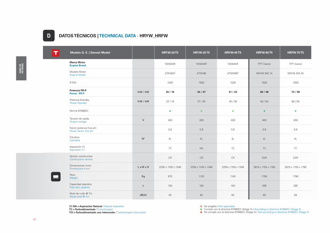
51
Modelo G. E. | Genset Model HRYW-20 T5 HRYW-35 T5 HRYW-45 T5 HRFW-60 T5 HRFW-75 T5
Marca Motor
Engine Brand YANMAR YANMAR YANMAR FPT (Iveco) FPT (Iveco)
Modelo Motor Engine Model
4TNV84T 4TNV98 4TNW98T NEF45 SM 1A NEF45 SM 2A
R.P.M. 1500 1500 1500 1500 1500
Potencia P.R.P.
Power P.R.P. kVA / kW 20 / 16 34 / 27 41 / 33 60 / 48 73 / 58
Potencia StandbyPower Standby
kVA / kW 22 / 18 37 / 30 45 / 36 63 / 50 80 / 64
Norma 97/68/EC
Tensión de salidaOutput voltage
V 400 400 400 400 400
Factor potencia Cos phiPower factor Cos phi
0,8 0,8 0,8 0,8 0,8
CilindrosCylindres
Nº 4L 4L 4L 4L 4L
Aspiración (1)Aspiration (1)
TC NA TC TC TC
Versión constructivaConstructive version
CR CR CR D2R D2R
Dimensiones (mm) Dimensions (mm)
L x W x H 2250 x 1100 x 1348 2250 x 1100 x 1348 2250 x 1100 x 1348 2810 x 1150 x 1780 2810 x 1150 x 1780
PesoWeight
Kg 975 1130 1140 1780 1780
Capacidad depósitoFuel tank capacity
L 100 100 100 285 285
Nivel de ruido @ 7mNoise level @ 7m
dB(A) 55 62 62 65 64
DATOS TÉCNICOS | TECHNICAL DATA · HRYW_HRFWD
(1) NA = Aspiración Natural / Natural AspiratedTC = Turboalimentado / TurbochargedTCI = Turboalimentado con intercooler / Turbocharged intercooled
No exigible / Not applicable Cumple con la directiva 97/68/EC (Stage II) / According to directive 97/68/EC (Stage II) No cumple con la directiva 97/68/EC (Stage II) / Not according to directive 97/68/EC (Stage II)
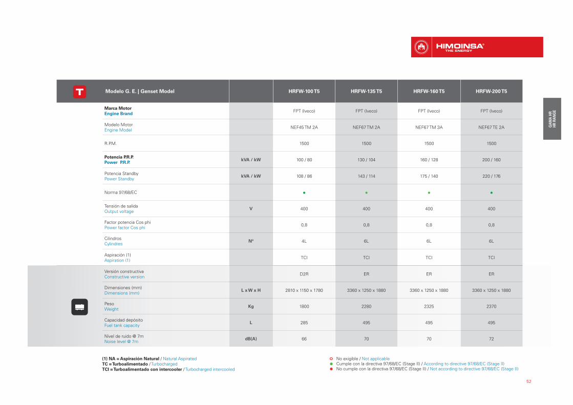
52
Modelo G. E. | Genset Model HRFW-100 T5 HRFW-135 T5 HRFW-160 T5 HRFW-200 T5
Marca Motor
Engine Brand FPT (Iveco) FPT (Iveco) FPT (Iveco) FPT (Iveco)
Modelo Motor Engine Model
NEF45 TM 2A NEF67 TM 2A NEF67 TM 3A NEF67 TE 2A
R.P.M. 1500 1500 1500 1500
Potencia P.R.P.
Power P.R.P. kVA / kW 100 / 80 130 / 104 160 / 128 200 / 160
Potencia StandbyPower Standby
kVA / kW 108 / 86 143 / 114 175 / 140 220 / 176
Norma 97/68/EC
Tensión de salidaOutput voltage
V 400 400 400 400
Factor potencia Cos phiPower factor Cos phi
0,8 0,8 0,8 0,8
CilindrosCylindres
Nº 4L 6L 6L 6L
Aspiración (1)Aspiration (1)
TCI TCI TCI TCI
Versión constructivaConstructive version
D2R ER ER ER
Dimensiones (mm) Dimensions (mm)
L x W x H 2810 x 1150 x 1780 3360 x 1250 x 1880 3360 x 1250 x 1880 3360 x 1250 x 1880
PesoWeight
Kg 1800 2280 2325 2370
Capacidad depósitoFuel tank capacity
L 285 495 495 495
Nivel de ruido @ 7mNoise level @ 7m
dB(A) 66 70 70 72
(1) NA = Aspiración Natural / Natural AspiratedTC = Turboalimentado / TurbochargedTCI = Turboalimentado con intercooler / Turbocharged intercooled
No exigible / Not applicable Cumple con la directiva 97/68/EC (Stage II) / According to directive 97/68/EC (Stage II) No cumple con la directiva 97/68/EC (Stage II) / Not according to directive 97/68/EC (Stage II)
53
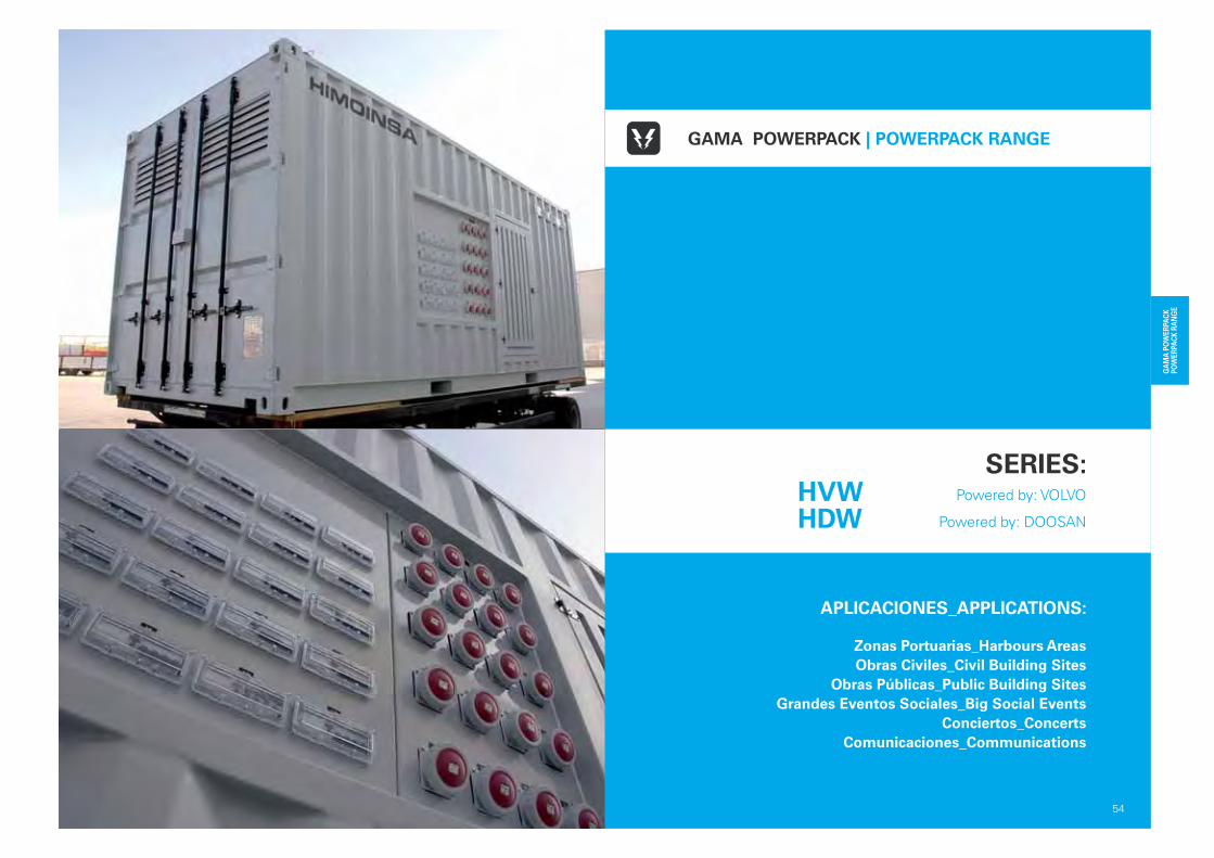
APLICACIONES_APPLICATIONS:
Zonas Portuarias_Harbours Areas
Obras Civiles_Civil Building Sites
Obras Públicas_Public Building Sites
Grandes Eventos Sociales_Big Social Events
Conciertos_Concerts
Comunicaciones_Communications
54
GAMA POWERPACK | POWERPACK RANGE
SERIES: Powered by: VOLVO
Powered by: DOOSAN
HVWHDW
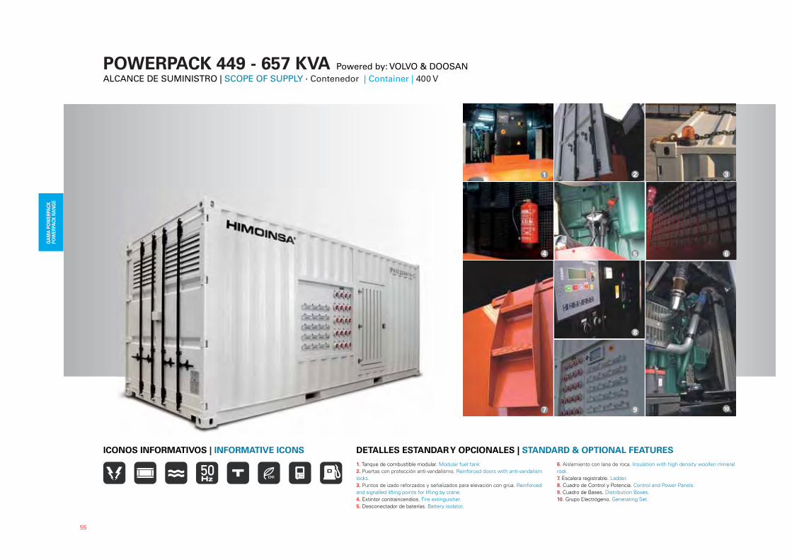
POWERPACK 449 - 657 KVA Powered by: VOLVO & DOOSANALCANCE DE SUMINISTRO | SCOPE OF SUPPLY · Contenedor | Container | 400 V
1. Tanque de combustible modular. Modular fuel tank
2. Puertas con protección anti-vandalismo. Reinforced doors with anti-vandalism
locks.
3. Puntos de izado reforzados y señalizados para elevación con grúa. Reinforced
and signalled lifting points for lifting by crane.
4. Extintor contraincendios. Fire extinguisher.
5. Desconectador de baterías. Battery isolator.
6. Aislamiento con lana de roca. Insulation with high density woollen mineral
rock.
7. Escalera registrable. Ladder.
8. Cuadro de Control y Potencia. Control and Power Panels.
9. Cuadro de Bases. Distribution Boxes.
10. Grupo Electrógeno. Generating Set.
DETALLES ESTANDAR Y OPCIONALES | STANDARD & OPTIONAL FEATURES
2 3
5
6
7
6
10
8
9
1
4
55
ICONOS INFORMATIVOS | INFORMATIVE ICONS
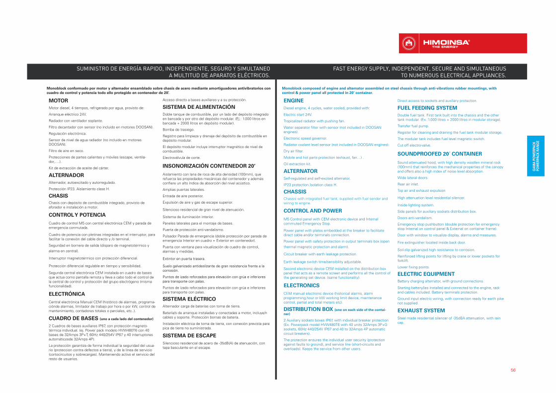
Monoblock conformado por motor y alternador ensamblado sobre chasis de acero mediante amortiguadores antivibratorios con
cuadro de control y potencia todo ello protegido en contenedor de 20’.
MOTOR
Motor diesel, 4 tiempos, refrigerado por agua, provisto de:
Arranque eléctrico 24V.
Radiador con ventilador soplante.
Filtro decantador con sensor (no incluido en motores DOOSAN).
Regulación electrónica.
Sensor de nivel de agua radiador (no incluido en motores DOOSAN).
Filtro de aire en seco.
Protecciones de partes calientes y móviles (escape, ventila-dor,….).
Kit de extracción de aceite del cárter.
ALTERNADOR
Alternador, autoexcitado y autorregulado.
Protección IP23. Aislamiento clase H.
CHASIS
Chasis con depósito de combustible integrado, provisto de aforador e instalación a motor.
CONTROL Y POTENCIA
Cuadro de control M5 con central electrónica CEM y parada deemergencia conmutada.
Cuadro de potencia con pletinas integradas en el interruptor, para facilitar la conexión del cable directo y /o terminal.
Seguridad en bornera de salida (disparo de magnetotérmico y
alarma en central).
Interruptor magnetotérmico con protección diferencial.
Protección diferencial regulable en tiempo y sensibilidad.
Segunda central electrónica CEM instalada en cuadro de bases que actua como pantalla remota y lleva a cabo todo el control de la central de control y protección del grupo electrógeno (misma funcionalidad).
ELECTRÓNICA
Central electrónica Manual CEM (histórico de alarmas, programa-ciónde alarmas, limitador de trabajo por hora o por kW, control demantenimiento, contadores totales o parciales, etc..).
CUADRO DE BASES (uno a cada lado del contenedor)
2 Cuadros de bases auxiliares IP67, con protección magneto-térmica individual. (ej. Power pack modelo HVW480T6 con 40 bases de 32Amps 3P+T, 60Hz 440/254V IP67 y 40 interruptores automáticosde 32Amps 4P).
La protección garantiza de forma individual la seguridad del usua-rio (proteccion contra defectos a tierra), y de la línea de servicio (cortocircuitos y sobrecargas). Manteniendo activo el servicio del resto de usuarios.
Acceso directo a bases auxiliares y a su protección.
SISTEMA DE ALIMENTACIÓN
Doble tanque de combustible, por un lado del depósito integradoen bancada y por otro del depósito modular. (Ej.: 1.000 litros enbancada + 2000 litros en depósito modular).
Bomba de trasiego.
Registro para limpieza y drenaje del depósito de combustible en depósito modular.
El depósito modular incluye interruptor magnético de nivel de combustible.
Electroválvula de corte.
INSONORIZACIÓN CONTENEDOR 20’
Aislamiento con lana de roca de alta densidad (100mm), que refuerza las propiedades mecánicas del contenedor y además confiere un alto índice de absorción del nivel acústico.
Amplias puertas laterales.
Entrada de aire posterior.
Expulsión de aire y gas de escape superior.
Silencioso residencial de gran nivel de atenuación.
Sistema de iluminación interior.
Paneles laterales para el montaje de bases.
Puerta de protección anti-vandalismo.
Pulsador Parada de emergencia (doble protección por parada deemergencia Interior en cuadro + Exterior en contenedor).
Puerta con ventana para visualización de cuadro de control, alarmas y medidas.
Extintor en puerta trasera.
Suelo galvanizado antideslizante de gran resistencia frente a la corrosión.
Puntos de izado reforzados para elevación con grúa e inferiores para transporte con palas.
Puntos de izado reforzados para elevación con grúa e inferiores para transporte con palas.
SISTEMA ELÉCTRICO
Alternador carga de baterías con toma de tierra.
Batería/s de arranque instaladas y conectadas a motor, incluye/n cables y soporte. Protección bornas de batería.
Instalación eléctrica de toma de tierra, con conexión prevista parapica de tierra no suministrada.
SISTEMA DE ESCAPE
Silencioso residencial de acero de -35dB(A) de atenuación, con tapa basculante en el escape.
Monoblock composed of engine and alternator assembled on steel chassis through anti-vibrations rubber mountings, with
control & power panel all protected in 20’ container.
ENGINE
Diesel engine, 4 cycles, water cooled, provided with:
Electric start 24V.
Tropicalized radiator with pushing fan.
Water separator filter with sensor (not included in DOOSAN engines).
Electronic speed governor.
Radiator coolant level sensor (not included in DOOSAN engines).
Dry air filter.
Mobile and hot parts protection (exhaust, fan…) .
Oil extraction kit.
ALTERNATOR
Self-regulated and self-excited alternator.
IP23 protection.Isolation class H.
CHASSIS
Chassis with integrated fuel tank, supplied with fuel sender and wiring to engine.
CONTROL AND POWER
M5 Control panel with CEM electronic device and Internalcommuted Emergency Stop.
Power panel with plates embedded at the breaker to facilitate direct cable and/or terminals connection.
Power panel with safety protection in output terminals box (open
thermal magnetic protection and alarm).
Circuit breaker with earth leakage protection.
Earth leakage switch time/sensibility adjustable.
Second electronic device CEM installed on the distribution box panel that acts as a remote screen and performs all the control of the generating set device. (same functionality).
ELECTRONICS
CEM manual electronic device (historical alarms, alarm programming,hour or kW working limit device, maintenance control, partial and total meters etc).
DISTRIBUTION BOX (one on each side of the contai-
ner)
2 Auxiliary sockets boxes IP67, with individual breaker protection(Ex. Powerpack model HVW480T6 with 40 units 32Amps 3P+Gsockets, 60Hz 440/254V IP67 and 40 to 32Amps 4P automaticcircuit breakers).
The protection ensures the individual user security (protection against faults to ground), and service line (short-circuits and overloads). Keeps the service from other users.
Direct access to sockets and auxiliary protection.
FUEL FEEDING SYSTEM
Double fuel tank. First tank built into the chassis and the other tank modular. (Ex.:1.000 litres + 2000 litres in modular storage).
Transfer fuel pump.
Register for cleaning and draining the fuel tank modular storage.
The modular tank includes fuel level magnetic switch.
Cut off electro-valve.
SOUNDPROOFED 20´ CONTAINER
Sound attenuated hood, with high density woollen mineral rock(100mm) that reinforces the mechanical properties of the canopyand offers also a high index of noise level absorption.
Wide lateral doors.
Rear air inlet.
Top air and exhaust expulsion
High attenuation level residential silencer.
Inside lighting system.
Side panels for auxiliary sockets distribution box.
Doors anti-vandalism.
Emergency stop pushbutton (double protection for emergency stop Internal on control panel & External on container frame).
Door with window to visualize display, alarms and measures.
Fire extinguisher located inside back door.
Soil-slip galvanized high resistance to corrosion.
Reinforced lifting points for lifting by crane or lower pockets forforklift.
Lower fixing points.
ELECTRIC EQUIPMENT
Battery charging alternator, with ground connections.
Starting battery/ies installed and connected to the engine, rack and cables included. Battery terminals protection.
Ground input electric wiring, with connection ready for earth pikenot supplied.
EXHAUST SYSTEM
Steel made residential silencer of -35dBA attenuation, with rain cap.
SUMINISTRO DE ENERGÍA RAPIDO, INDEPENDIENTE, SEGURO Y SIMULTANEO A MULTITUD DE APARATOS ELÉCTRICOS.
56
FAST ENERGY SUPPLY, INDEPENDENT, SECURE AND SIMULTANEOUS TO NUMEROUS ELECTRICAL APPLIANCES.
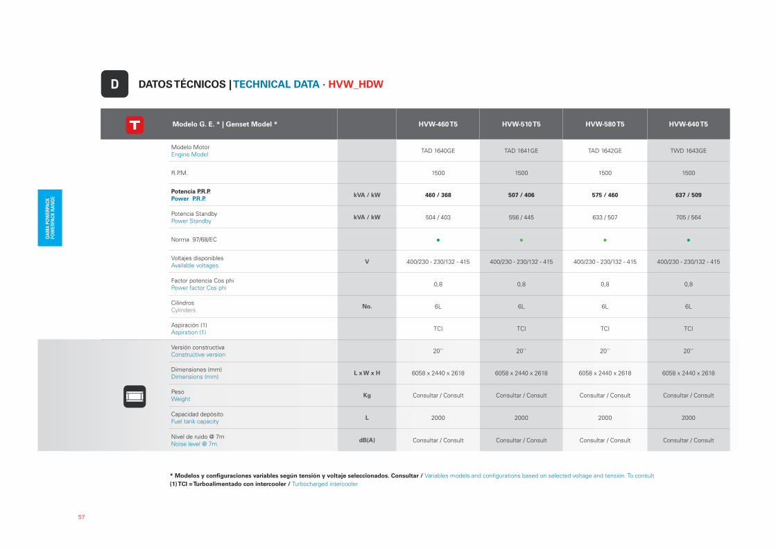
* Modelos y configuraciones variables según tensión y voltaje seleccionados. Consultar / Variables models and configurations based on selected voltage and tension. To consult
(1) TCI = Turboalimentado con intercooler / Turbocharged intercooler
57
Modelo G. E. * | Genset Model * HVW-460 T5 HVW-510 T5 HVW-580 T5 HVW-640 T5
Modelo MotorEngine Model
TAD 1640GE TAD 1641GE TAD 1642GE TWD 1643GE
R.P.M. 1500 1500 1500 1500
Potencia P.R.P.
Power P.R.P.kVA / kW 460 / 368 507 / 406 575 / 460 637 / 509
Potencia StandbyPower Standby
kVA / kW 504 / 403 556 / 445 633 / 507 705 / 564
Norma 97/68/EC
Voltajes disponiblesAvailable voltages
V 400/230 - 230/132 - 415 400/230 - 230/132 - 415 400/230 - 230/132 - 415 400/230 - 230/132 - 415
Factor potencia Cos phiPower factor Cos phi
0,8 0,8 0,8 0,8
CilindrosCylinders
No. 6L 6L 6L 6L
Aspiración (1)Aspiration (1)
TCI TCI TCI TCI
Versión constructivaConstructive version
20'' 20'' 20'' 20''
Dimensiones (mm)Dimensions (mm)
L x W x H 6058 x 2440 x 2618 6058 x 2440 x 2618 6058 x 2440 x 2618 6058 x 2440 x 2618
PesoWeight
Kg Consultar / Consult Consultar / Consult Consultar / Consult Consultar / Consult
Capacidad depósitoFuel tank capacity
L 2000 2000 2000 2000
Nivel de ruido @ 7mNoise level @ 7m
dB(A) Consultar / Consult Consultar / Consult Consultar / Consult Consultar / Consult
DATOS TÉCNICOS | TECHNICAL DATA · HVW_HDWD

58
Modelo G. E. * | Genset Model * HDW-450 T5 HDW-525 T5 HDW-670 T5
Modelo MotorEngine Model
P158FE P180LE P222FE
R.P.M. 1500 1500 1500
Potencia P.R.P.
Power P.R.P.kVA / kW 449 / 359 503 / 403 657 / 525
Potencia StandbyPower Standby
kVA / kW 494 / 395 564 / 451 705 / 564
Norma 97/68/EC
Voltajes disponiblesAvailable voltages
V 400/230 - 230/132 - 415 400/230 - 230/132 - 415 400/230 - 230/132 - 415
Factor potencia Cos phiPower factor Cos phi
0,8 0,8 0,8
CilindrosCylinders
No. 8V 10V 12V
Aspiración (1)Aspiration (1)
TCI TCI TCI
Versión constructivaConstructive version
20'' 20'' 20''
Dimensiones (mm)Dimensions (mm)
L x W x H 6058 x 2440 x 2618 6058 x 2440 x 2618 6058 x 2440 x 2618
PesoWeight
Kg Consultar / Consult Consultar / Consult Consultar / Consult
Capacidad depósitoFuel tank capacity
L 2000 2000 2000
Nivel de ruido @ 7mNoise level @ 7m
dB(A) Consultar / Consult Consultar / Consult Consultar / Consult
No exigible / Not applicable Cumple con la directiva 97/68/EC (Stage II) / According to directive 97/68/EC (Stage II) No cumple con la directiva 97/68/EC (Stage II) / Not according to directive 97/68/EC (Stage II)
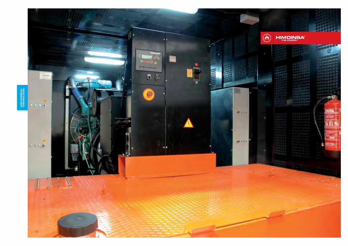
59

60
Developing countries; High energy needs• Diesel Fuel • 20MVA ... 50MVA • Continuous duty Developing countries; primary systems back up • Diesel Fuel • 1MVA ... 5MVA • Prime power or Stand by duty
Developed countries; remotes areas (islands, mountains, etc.) • Diesel Fuel • IMVA ... 10MVA • Continuous dutyDeveloped countries; support to utility• Diesel fuel; • IMVA ... 5MVA; • Prime power or Stand by duty
Product especially designed for:
Paises en desarrollo, alta demanda de energia• Gasóleo• 20MVA ... 50MVA • Trabajo Continuo
Paises en desarrollo, sistemas de back up • Gasóleo• 1MVA ... 5MVA • Energía primaria o Trabajo en Stand By
Paises desarrollados, generación en areas remotas (islas, montañas, etc.) • Gasóleo• IMVA ... 10MVA • Trabajo ContinuoPaises en desarrollo, soporte para utili-dades• Gasóleo; • IMVA ... 5MVA; • Energía primaria o Trabajo en Stand By
Producto especialmente diseñado para:
GAMA POWERPLANT | POWERPLANT RANGE

������������ � ������������������������������� ������������
Modulo power plantPotencia:
1800KVA PRP or 1500KVA COP @ 50Hz
Potencia de salida:
3,3kV, 5kV, 11kV, 15kV @ 50Hz;
Motor diesel:
Container ISO 40’ HC, apto para transporte y para montaje en trailer (no incluido)Funciones de sincronizacion, entre grupos y/o red publica;Disponibles: SCADA, BAS, interface de supervision;Sistema de llenado automático combustible para una capacidad de operación continua;By-pass de filtros aceite y gasoil;Sistema contra-incendio;Trading GPS.
Power Plant modulePower:1800KVA PRP or 1500KVA COP @ 50Hz
Output Voltage:
3,3kV, 5kV, 11kV, 15kV @ 50Hz;
Diesel Engine:
Container ISO 40’ HC, suitable to be transported and fitted on a trailer (not included);Synchronization functions, between genset or with an utility;Available BAS, SCADA, supervising interface;Fuel refilling system and automatic oil refilling for a continuous operation capability;Oil and Diesel Filter by-pass;Fire extinguishing system;GPS tracking;
61
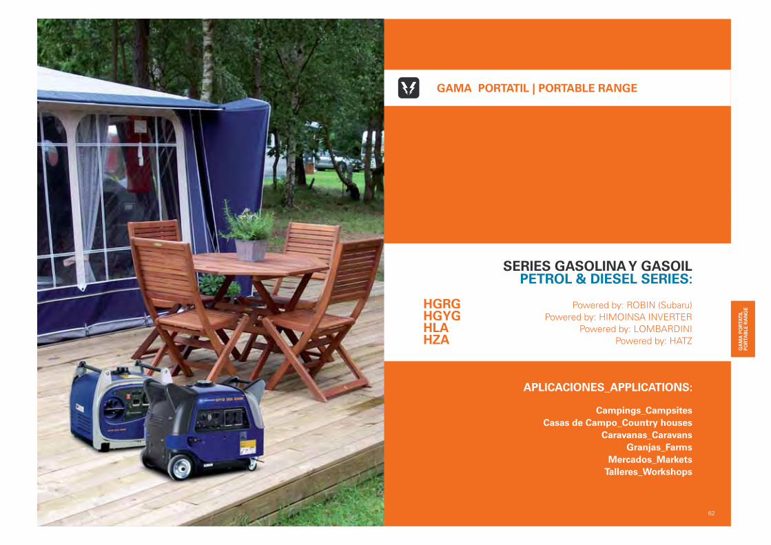
APLICACIONES_APPLICATIONS:
Campings_Campsites
Casas de Campo_Country houses
Caravanas_Caravans
Granjas_Farms
Mercados_Markets
Talleres_Workshops
62
GAMA PORTATIL | PORTABLE RANGE
SERIES GASOLINA Y GASOILPETROL & DIESEL SERIES:
Powered by: ROBIN (Subaru)
Powered by: HIMOINSA INVERTER
Powered by: LOMBARDINI
Powered by: HATZ
HGRGHGYGHLAHZA

HGRG 2.200 W - 5.600 W Powered by: ROBIN (SUBARU)ALCANCE DE SUMINISTRO | SCOPE OF SUPPLY · GE_Tubular GASOLINA_AIRE | Tubular_GS PETROL_AIR | 400 - 220 V
Monoblock conformado por:
MOTOR
Motor gasolina, monocilindrico, refrigerado por AIRE, O.H.C. (árbol de levas sin cabezas) o O.H.V. (válvulas en cabezas), según modelo y alternador de 2 polos, autoexcitado y autorregulado, protección IP21, aislamiento clase H, ensamblados sobre chasis de acero tubular mediante amortiguadores antivibratorios de caucho.
Silencioso para cumplimiento de normas de ruido.
Tanque de gran capacidad (sólo disponible en la serie Lujo).
Protecciones del escape.
CONTROL Y POTENCIA
Cuadro eléctrico con diferencial (no disponible para modelo GRG28 RM).
SISTEMA ELÉCTRICOBatería de arranque, incluye cables y soporte. (suministro están-dar en versión eléctrica)
EXTRAS
Manual de instrucciones de uso y mantenimiento.
Embalaje de cartón.
OPCIONAL
Kit de ruedas con asideras. (excepto modelo GRG 28 RM)
Monoblock made of:
ENGINE
Diesel engine 4 strokes, single-cylinder, AIR cooled, O.H.C. (Overhead camshaft) o O.H.V. (overhead valves), depending on model and 2 poles alternator, self excited and auto regulated, pro-tection IP21, class H insulation, coupled on tubular steel chassis by means of rubber antivibrations shock absorbers.
Silencer to comply with noise level regulations.
High capacity tank (only available in the deluxe series).
Exhaust guards.
CONTROL AND POWER
Electrical control panel with differential – see scope of supply table-. (not available for model GRG28 RM).
ELECTRIC EQUIPMENTStarting battery, includes cables and rack. (Standard supply with Electric version).
EXTRAS
Use & maintenance instructions manual.
Cartoon packing.
OPTIONAL
Wheel Kit with handles. (except GRG28 RM)
63
1. Tanque de gran capacidad. High capacity tank.
2. O.H.C. (árbol de levas en cabezas). O.H.C. (Overhead camshaft).
3. O.H.V. (válvulas en cabezas). O.H.V. (overhead valves).
4. Batería de arranque. Starting battery.
DETALLES TÉCNICOS | TECHNICAL FEATURES
43
21
ICONOS INFORMATIVOS | INFORMATIVE ICONS
*
* Ver cuadros de control en la página 74_Check control panels on page 74.
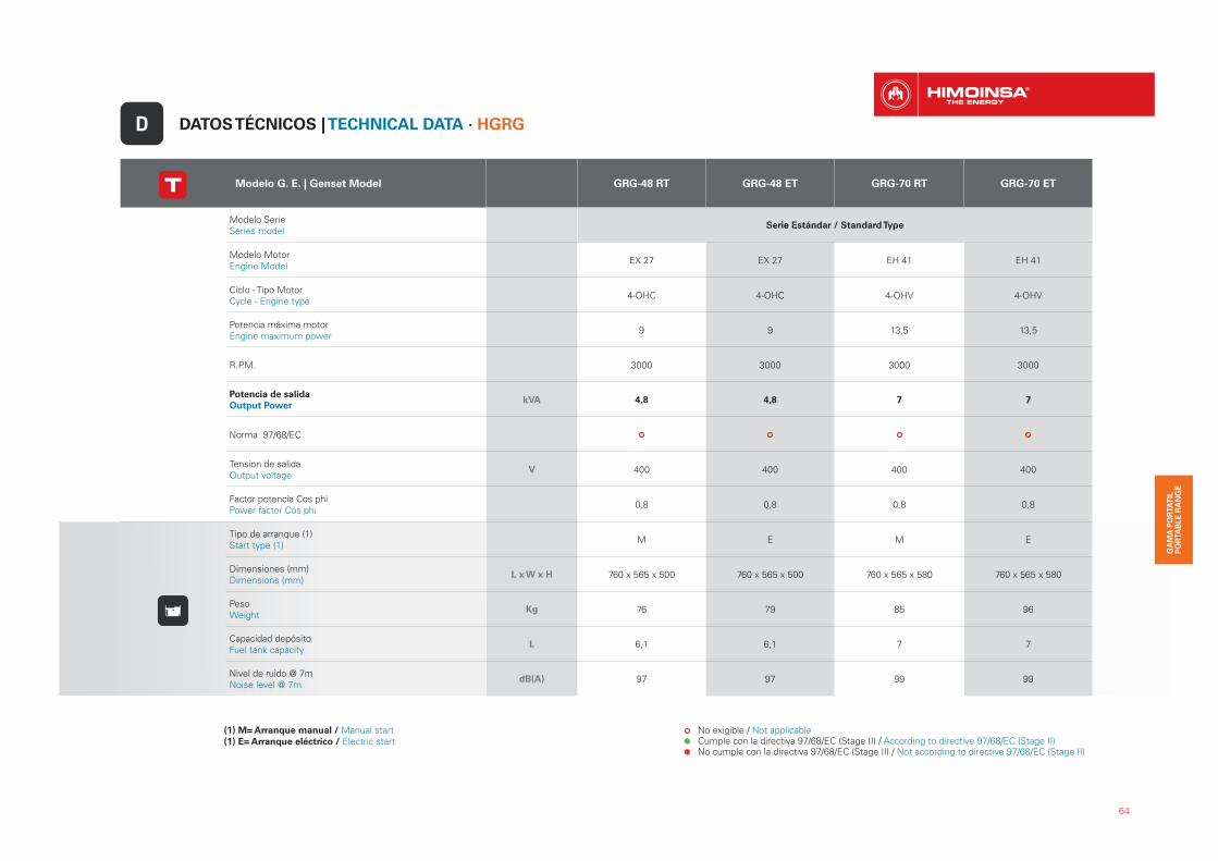
Modelo G. E. | Genset Model GRG-48 RT GRG-48 ET GRG-70 RT GRG-70 ET
Modelo SerieSeries model
Serie Estándar / Standard Type
Modelo MotorEngine Model
EX 27 EX 27 EH 41 EH 41
Ciclo - Tipo MotorCycle - Engine type
4-OHC 4-OHC 4-OHV 4-OHV
Potencia máxima motorEngine maximum power
9 9 13,5 13,5
R.P.M. 3000 3000 3000 3000
Potencia de salida
Output PowerkVA 4,8 4,8 7 7
Norma 97/68/EC
Tension de salidaOutput voltage
V 400 400 400 400
Factor potencia Cos phiPower factor Cos phi
0,8 0,8 0,8 0,8
Tipo de arranque (1)Start type (1)
M E M E
Dimensiones (mm)Dimensions (mm)
L x W x H 760 x 565 x 500 760 x 565 x 500 760 x 565 x 580 760 x 565 x 580
PesoWeight
Kg 76 79 85 96
Capacidad depósitoFuel tank capacity
L 6,1 6,1 7 7
Nivel de ruido @ 7mNoise level @ 7m
dB(A) 97 97 99 99
DATOS TÉCNICOS | TECHNICAL DATA · HGRGD
(1) M= Arranque manual / Manual start(1) E= Arranque eléctrico / Electric start
No exigible / Not applicable Cumple con la directiva 97/68/EC (Stage II) / According to directive 97/68/EC (Stage II) No cumple con la directiva 97/68/EC (Stage II) / Not according to directive 97/68/EC (Stage II)
64
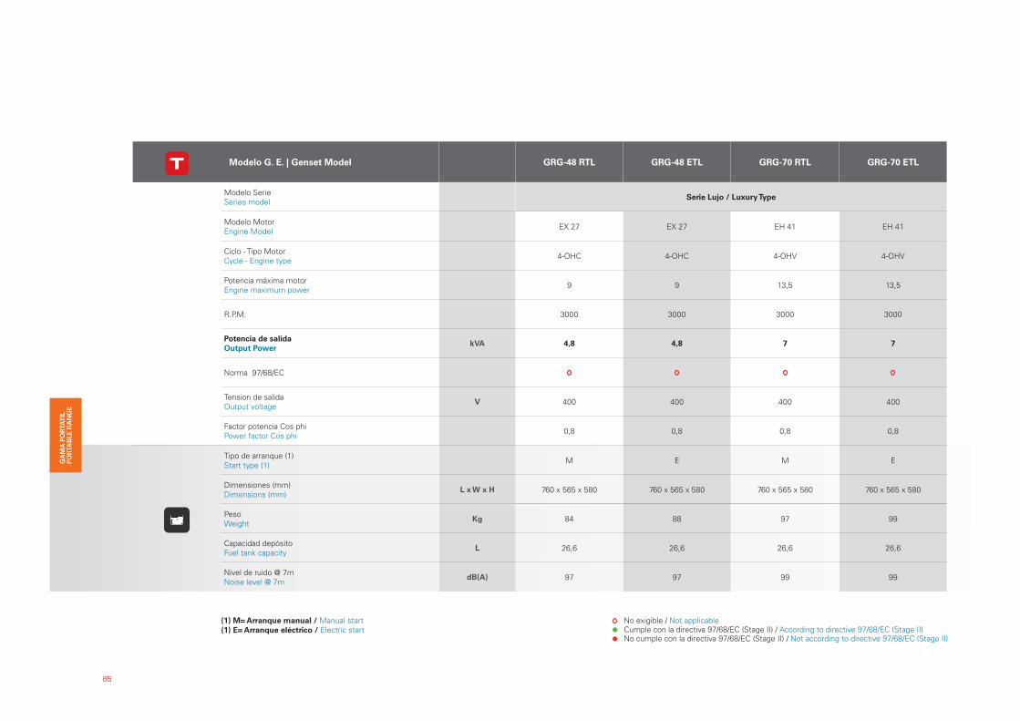
65
(1) M= Arranque manual / Manual start(1) E= Arranque eléctrico / Electric start
No exigible / Not applicable Cumple con la directiva 97/68/EC (Stage II) / According to directive 97/68/EC (Stage II) No cumple con la directiva 97/68/EC (Stage II) / Not according to directive 97/68/EC (Stage II)
Modelo G. E. | Genset Model GRG-48 RTL GRG-48 ETL GRG-70 RTL GRG-70 ETL
Modelo SerieSeries model
Serie Lujo / Luxury Type
Modelo MotorEngine Model
EX 27 EX 27 EH 41 EH 41
Ciclo - Tipo MotorCycle - Engine type
4-OHC 4-OHC 4-OHV 4-OHV
Potencia máxima motorEngine maximum power
9 9 13,5 13,5
R.P.M. 3000 3000 3000 3000
Potencia de salida
Output PowerkVA 4,8 4,8 7 7
Norma 97/68/EC
Tension de salidaOutput voltage
V 400 400 400 400
Factor potencia Cos phiPower factor Cos phi
0,8 0,8 0,8 0,8
Tipo de arranque (1)Start type (1)
M E M E
Dimensiones (mm)Dimensions (mm)
L x W x H 760 x 565 x 580 760 x 565 x 580 760 x 565 x 580 760 x 565 x 580
PesoWeight
Kg 84 88 97 99
Capacidad depósitoFuel tank capacity
L 26,6 26,6 26,6 26,6
Nivel de ruido @ 7mNoise level @ 7m
dB(A) 97 97 99 99
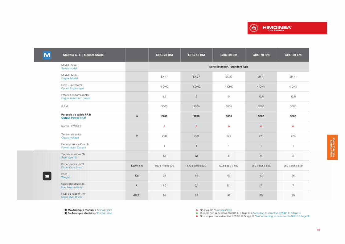
66
(1) M= Arranque manual / Manual start(1) E= Arranque eléctrico / Electric start
No exigible / Not applicable Cumple con la directiva 97/68/EC (Stage II) / According to directive 97/68/EC (Stage II) No cumple con la directiva 97/68/EC (Stage II) / Not according to directive 97/68/EC (Stage II)
Modelo G. E. | Genset Model GRG-28 RM GRG-48 RM GRG-48 EM GRG-70 RM GRG-70 EM
Modelo SerieSeries model
Serie Estándar / Standard Type
Modelo MotorEngine Model
EX 17 EX 27 EX 27 EH 41 EH 41
Ciclo - Tipo MotorCycle - Engine type
4-OHC 4-OHC 4-OHC 4-OHV 4-OHV
Potencia máxima motorEngine maximum power
5,7 9 9 13,5 13,5
R.P.M. 3000 3000 3000 3000 3000
Potencia de salida P.R.P.
Output Power P.R.P.W 2200 3800 3800 5600 5600
Norma 97/68/EC
Tension de salidaOutput voltage
V 220 220 220 220 220
Factor potencia Cos phiPower factor Cos phi
1 1 1 1 1
Tipo de arranque (1)Start type (1)
M M E M E
Dimensiones (mm)Dimensions (mm)
L x W x H 600 x 440 x 420 673 x 550 x 500 673 x 550 x 500 760 x 565 x 580 760 x 565 x 580
PesoWeight
Kg 38 59 62 83 86
Capacidad depósitoFuel tank capacity
L 3,6 6,1 6,1 7 7
Nivel de ruido @ 7mNoise level @ 7m
dB(A) 98 97 97 99 99

67
(1) M= Arranque manual / Manual start(1) E= Arranque eléctrico / Electric start
No exigible / Not applicable Cumple con la directiva 97/68/EC (Stage II) / According to directive 97/68/EC (Stage II) No cumple con la directiva 97/68/EC (Stage II) / Not according to directive 97/68/EC (Stage II)
Modelo G. E. | Genset Model GRG-48 RML GRG-48 EML GRG-70 RML GRG-70 EML
Modelo SerieSeries model
Serie Lujo / Luxury Type
Modelo MotorEngine Model
EX 27 EX 27 EH 41 EH 41
Ciclo - Tipo MotorCycle - Engine type
4-OHC 4-OHC 4-OHV 4-OHV
Potencia máxima motorEngine maximum power
9 9 13,5 13,5
R.P.M. 3000 3000 3000 3000
Potencia de salida P.R.P.
Output Power P.R.P.W 3800 3800 5600 5600
Norma 97/68/EC
Tension de salidaOutput voltage
V 220 220 220 220
Factor potencia Cos phiPower factor Cos phi
1 1 1 1
Tipo de arranque (1)Start type (1)
M E M E
Dimensiones (mm)Dimensions (mm)
L x W x H 760 x 565 x 580 760 x 565 x 580 760 x 565 x 580 760 x 565 x 580
PesoWeight
Kg 68 72 86 88
Capacidad depósitoFuel tank capacity
L 26,6 26,6 26,6 26,6
Nivel de ruido @ 7mNoise level @ 7m
dB(A) 97 97 99 99
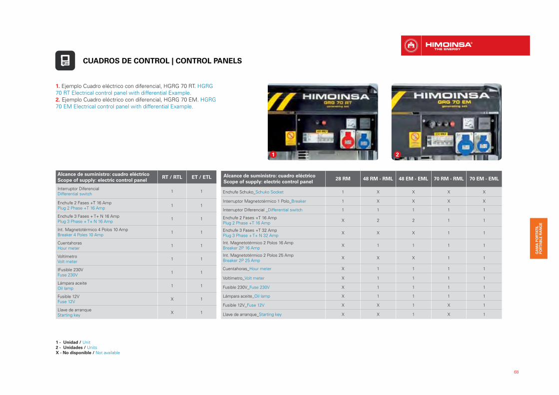
68
Alcance de suministro: cuadro eléctrico
Scope of supply: electric control panelRT / RTL ET / ETL
Interruptor Diferencial Differential switch
1 1
Enchufe 2 Fases +T 16 Amp Plug 2 Phase +T 16 Amp
1 1
Enchufe 3 Fases + T+ N 16 Amp Plug 3 Phase + T+ N 16 Amp
1 1
Int. Magnetotérmico 4 Polos 10 Amp Breaker 4 Poles 10 Amp
1 1
Cuentahoras Hour meter
1 1
Voltímetro Volt meter
1 1
IFusible 230V Fuse 230V
1 1
Lámpara aceite Oil lamp
1 1
Fusible 12V Fuse 12V
X 1
Llave de arranque Starting key
X 1
Alcance de suministro: cuadro eléctrico
Scope of supply: electric control panel28 RM 48 RM - RML 48 EM - EML 70 RM - RML 70 EM - EML
Enchufe Schuko_Schuko Socket 1 X X X X
Interruptor Magnetotérmico 1 Polo_Breaker 1 X X X X
Interruptor Diferencial _Differential switch 1 1 1 1 1
Enchufe 2 Fases +T 16 Amp Plug 2 Phase +T 16 Amp
X 2 2 1 1
Enchufe 3 Fases +T 32 AmpPlug 3 Phase + T+ N 32 Amp
X X X 1 1
Int. Magnetotérmico 2 Polos 16 Amp Breaker 2P 16 Amp
X 1 1 1 1
Int. Magnetotérmico 2 Polos 25 Amp Breaker 2P 25 Amp
X X X 1 1
Cuentahoras_Hour meter X 1 1 1 1
Voltímetro_Volt meter X 1 1 1 1
Fusible 230V_Fuse 230V X 1 1 1 1
Lámpara aceite_Oil lamp X 1 1 1 1
Fusible 12V_Fuse 12V X X 1 X 1
Llave de arranque_Starting key X X 1 X 1
1. Ejemplo Cuadro eléctrico con diferencial, HGRG 70 RT. HGRG
70 RT Electrical control panel with differential Example.
2. Ejemplo Cuadro eléctrico con diferencial, HGRG 70 EM. HGRG
70 EM Electrical control panel with differential Example.
1 2
CUADROS DE CONTROL | CONTROL PANELS
1 - Unidad / Unit2 - Unidades / UnitsX - No disponible / Not available
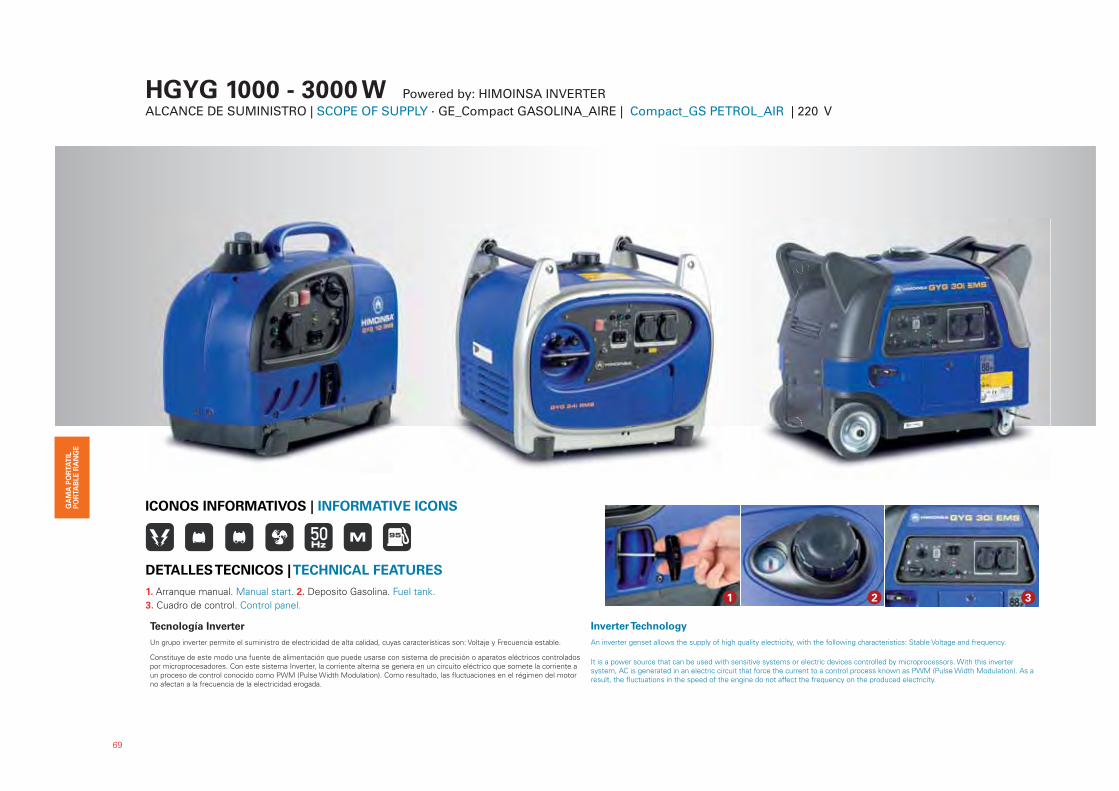
1
3
HGYG 1000 - 3000 W Powered by: HIMOINSA INVERTERALCANCE DE SUMINISTRO | SCOPE OF SUPPLY · GE_Compact GASOLINA_AIRE | Compact_GS PETROL_AIR | 220 V
Tecnología Inverter
Un grupo inverter permite el suministro de electricidad de alta calidad, cuyas características son: Voltaje y Frecuencia estable.
Constituye de este modo una fuente de alimentación que puede usarse con sistema de precisión o aparatos eléctricos controlados por microprocesadores. Con este sistema Inverter, la corriente alterna se genera en un circuito eléctrico que somete la corriente a un proceso de control conocido como PWM (Pulse Width Modulation). Como resultado, las fluctuaciones en el régimen del motor no afectan a la frecuencia de la electricidad erogada.
Inverter Technology
An inverter genset allows the supply of high quality electricity, with the following characteristics: Stable Voltage and frequency.
It is a power source that can be used with sensitive systems or electric devices controlled by microprocessors. With this invertersystem, AC is generated in an electric circuit that force the current to a control process known as PWM (Pulse Width Modulation). As a result, the fluctuations in the speed of the engine do not affect the frequency on the produced electricity.
111111
33333333333333333333333333333333333333333333333
1. Arranque manual. Manual start. 2. Deposito Gasolina. Fuel tank.
3. Cuadro de control. Control panel.
DETALLES TECNICOS | TECHNICAL FEATURES
ICONOS INFORMATIVOS | INFORMATIVE ICONS
1 2 3
69
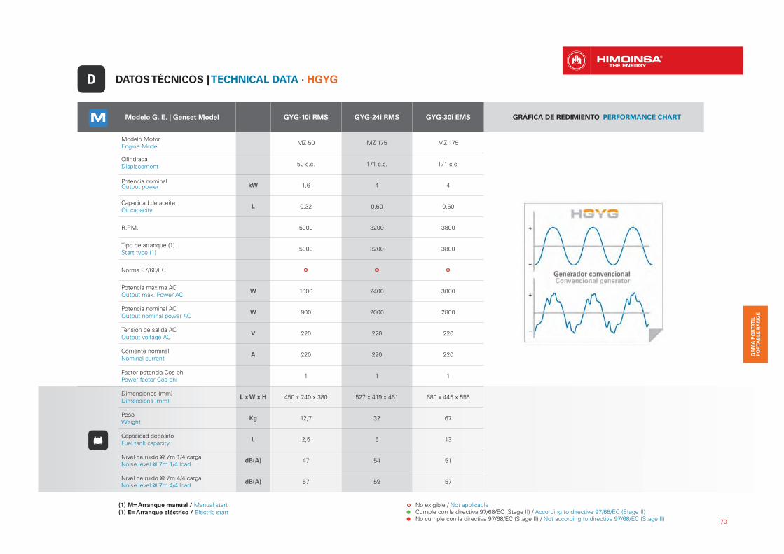
70
Modelo G. E. | Genset Model GYG-10i RMS GYG-24i RMS GYG-30i EMS GRÁFICA DE REDIMIENTO_PERFORMANCE CHART
Modelo Motor Engine Model
MZ 50 MZ 175 MZ 175
CilindradaDisplacement 50 c.c. 171 c.c. 171 c.c.
Potencia nominalOutput power kW 1,6 4 4
Capacidad de aceiteOil capacity
L 0,32 0,60 0,60
R.P.M. 5000 3200 3800
Tipo de arranque (1)Start type (1)
5000 3200 3800
Norma 97/68/EC
Potencia máxima ACOutput max. Power AC
W 1000 2400 3000
Potencia nominal ACOutput nominal power AC
W 900 2000 2800
Tensión de salida ACOutput voltage AC
V 220 220 220
Corriente nominalNominal current
A 220 220 220
Factor potencia Cos phiPower factor Cos phi
1 1 1
Dimensiones (mm) Dimensions (mm)
L x W x H 450 x 240 x 380 527 x 419 x 461 680 x 445 x 555
PesoWeight
Kg 12,7 32 67
Capacidad depósitoFuel tank capacity
L 2,5 6 13
Nivel de ruido @ 7m 1/4 cargaNoise level @ 7m 1/4 load
dB(A) 47 54 51
Nivel de ruido @ 7m 4/4 cargaNoise level @ 7m 4/4 load
dB(A) 57 59 57
DATOS TÉCNICOS | TECHNICAL DATA · HGYGD
(1) M= Arranque manual / Manual start(1) E= Arranque eléctrico / Electric start
No exigible / Not applicable Cumple con la directiva 97/68/EC (Stage II) / According to directive 97/68/EC (Stage II) No cumple con la directiva 97/68/EC (Stage II) / Not according to directive 97/68/EC (Stage II)
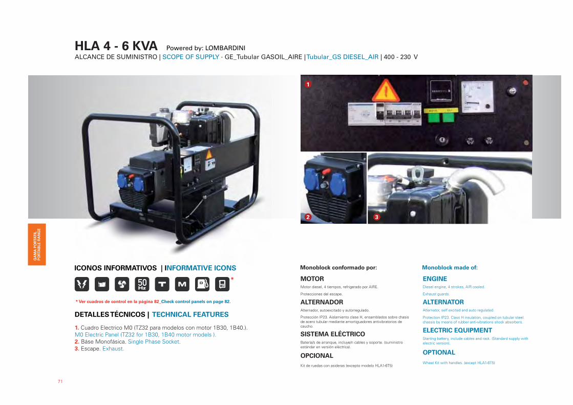
HLA 4 - 6 KVA Powered by: LOMBARDINI ALCANCE DE SUMINISTRO | SCOPE OF SUPPLY · GE_Tubular GASOIL_AIRE | Tubular_GS DIESEL_AIR | 400 - 230 V
Monoblock conformado por:
MOTORMotor diesel, 4 tiempos, refrigerado por AIRE.
Protecciones del escape.
ALTERNADORAlternador, autoexcitado y autorregulado.
Protección IP23. Aislamiento clase H, ensamblados sobre chasis de acero tubular mediante amortiguadores antivibratorios de caucho.
SISTEMA ELÉCTRICOBatería/s de arranque, incluye/n cables y soporte. (suministro estándar en versión eléctrica).
OPCIONAL
Kit de ruedas con asideras (excepto modelo HLA1-6T5)
Monoblock made of:
ENGINEDiesel engine, 4 strokes, AIR cooled.
Exhaust guards.
ALTERNATORAlternator, self excited and auto regulated.
Protection IP23. Class H insulation, coupled on tubular steel chassis by means of rubber anti-vibrations shock absorbers.
ELECTRIC EQUIPMENTStarting battery, include cables and rack. (Standard supply withelectric version).
OPTIONAL
Wheel Kit with handles. (except HLA1-6T5)
1
2 3
71
ICONOS INFORMATIVOS | INFORMATIVE ICONS
1. Cuadro Electrico M0 (TZ32 para modelos con motor 1B30, 1B40.).
M0 Electric Panel (TZ32 for 1B30, 1B40 motor models ).
2. Báse Monofásica. Single Phase Socket.
3. Escape. Exhaust.
DETALLES TÉCNICOS | TECHNICAL FEATURES
*
* Ver cuadros de control en la página 82_Check control panels on page 82.

72
Modelo G. E.
Genset ModelHLA1-6 T5 HLA3-4 T5 HLA3-6 T5
Modelo MotorEngine Model
4LD 820 L 15LD 350 15LD 440
R.P.M. 1500 3000 3000
Potencia P.R.P.
Power P.R.P.kVA / kW 5,8 / 4,7 4 / 3 6 / 5
Potencia StandbyPower Standby
kVA / kW 6,4 / 5,1 4,4 / 3,5 6,6 / 5,3
Norma 97/68/EC
Tension de salidaOutput voltage
V 400 400 400
Factor potencia Cos phiPower factor Cos phi
0,8 0,8 0,8
Tipo de arranque (1)Start type (1)
E M E
CilindrosCylinders
No. 1 1 1
Dimensiones (mm)Dimensions (mm)
L x W x H 1145 x 740 x 880 800 x 590 x 570 800 x 590 x 570
PesoWeight
Kg 212 125 140
Capacidad depósitoFuel tank capacity
L 7,2 4,3 5
DATOS TÉCNICOS | TECHNICAL DATA · HLAD
(1) M= Arranque manual / Manual start(1) E= Arranque eléctrico / Electric start
No exigible / Not applicable Cumple con la directiva 97/68/EC (Stage II) / According to directive 97/68/EC (Stage II) No cumple con la directiva 97/68/EC (Stage II) / Not according to directive 97/68/EC (Stage II)
Modelo G. E.
Genset ModelHLA1-5 M5 HLA3-4 M5 HLA3-6 M5
Modelo MotorEngine Model
4LD 820 L 15LD 350 15LD 440
R.P.M. 1500 3000 3000
Potencia P.R.P.
Power P.R.P.kVA / kW 4,7 / 4,7 3,2 / 3,2 4,8 / 4,8
Potencia StandbyPower Standby
kVA / kW 5,1 / 5,1 3,6 / 3,6 5,4 / 5,4
Norma 97/68/EC
Tension de salidaOutput voltage
V 230 230 230
Factor potencia Cos phiPower factor Cos phi
1 1 1
Tipo de arranque (1)Start type (1)
E M E
CilindrosCylinders
No. 1 1 1
Dimensiones (mm)Dimensions (mm)
L x W x H 1145 x 740 x 880 800 x 590 x 570 800 x 590 x 570
PesoWeight
Kg 218 125 140
Capacidad depósitoFuel tank capacity
L 7,2 4,3 5

HZA 3,7 - 9,9 KVA Powered by: HATZ ALCANCE DE SUMINISTRO | SCOPE OF SUPPLY · GE_Tubular GASOIL_AIRE | Tubular_GS DIESEL_AIR | 400 - 230 V
Monoblock conformado por:
MOTORMotor diesel, 4 tiempos, refrigerado por AIRE.
Protecciones del escape.
ALTERNADORAlternador, autoexcitado y autorregulado.
Protección IP23. Aislamiento clase H, ensamblados sobre chasis de acero tubular mediante amortiguadores antivibratorios de caucho.
SISTEMA ELÉCTRICO
Batería/s de arranque, incluye/n cables y soporte. (suministro están-dar en versión eléctrica).
OPCIONAL
Kit de ruedas con asideras
Monoblock made of:
ENGINEDiesel engine, 4 strokes, AIR cooled.
Exhaust guards.
ALTERNATORAlternator, self excited and auto regulated.
Protection IP23. Class H insulation, coupled on tubular steel chassis by means of rubber anti-vibrations shock absorbers.
ELECTRIC EQUIPMENT
Starting battery, include cables and rack. (Standard supply withelectric version).
OPTIONAL
Wheel Kit with handles. (except HLA1-6T5)
1. Cuadro Electrico M0 (TZ63 para modelos con motor 1D81S, 1D90S).
M0 Electric Panel (TZ36 for 1D81S, 1D90S motor models).
2. Kit de ruedas con asideras (OPCIONAL). Wheel Kit with handles
(OPTIONAL).
3. Batería/s de arranque. Starting Battery.
4. Deposito Gasolina Incorporado. Fuel Tank Incorporated.
73
ICONOS INFORMATIVOS | INFORMATIVE ICONS
DETALLES TÉCNICOS | TECHNICAL FEATURES
1
3 4
2
*
* Ver cuadros de control en la página 83_Check control panels on page 83.
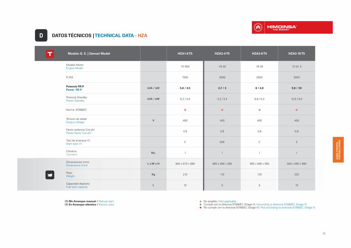
74
DATOS TÉCNICOS | TECHNICAL DATA · HZAD
Modelo G. E. | Genset Model HZA1-6 T5 HZA3-4 T5 HZA3-6 T5 HZA3-10 T5
Modelo MotorEngine Model
1D 90S 1B 30 1B 40 1D 81 S
R.P.M. 1500 3000 3000 3000
Potencia P.R.P.
Power P.R.P.kVA / kW 5,6 / 4,5 3,7 / 3 6 / 4,8 9,9 / 7,9
Potencia StandbyPower Standby
kVA / kW 6,2 / 4,9 4,2 / 3,4 6,6 / 5,3 10,6 / 8,5
Norma 97/68/EC
Tension de salidaOutput voltage
V 400 400 400 400
Factor potencia Cos phiPower factor Cos phi
0,8 0,8 0,8 0,8
Tipo de arranque (1)Start type (1)
E M/E E E
CilindrosCylinders
No. 1 1 1 1
Dimensiones (mm)Dimensions (mm)
L x W x H 940 x 570 x 680 805 x 590 x 585 805 x 590 x 585 940 x 590 x 680
PesoWeight
Kg 210 110 125 220
Capacidad depósitoFuel tank capacity
L 10 5 5 10
(1) M= Arranque manual / Manual start(1) E= Arranque eléctrico / Electric start
No exigible / Not applicable Cumple con la directiva 97/68/EC (Stage II) / According to directive 97/68/EC (Stage II) No cumple con la directiva 97/68/EC (Stage II) / Not according to directive 97/68/EC (Stage II)

75
Modelo G. E. | Genset Model HZA1-5 M5 HZA3-4 M5 HZA3-5 M5 HZA3-8 M5
Modelo MotorEngine Model
1D90S 1B 30 1B 40 1D 81 S
R.P.M. 1500 3000 3000 3000
Potencia P.R.P.
Power P.R.P.kVA / kW 4,5 / 4,5 3,2 / 3,2 4,9 / 4,9 7,7 / 7,7
Potencia StandbyPower Standby
kVA / kW 4,9 / 4,9 3,5 / 3,5 5,3 / 5,3 8,5 / 8,5
Norma 97/68/EC
Tension de salidaOutput voltage
V 230 230 230 230
Factor potencia Cos phiPower factor Cos phi
1 1 1 1
Tipo de arranque (1)Start type (1)
E M/E E E
CilindrosCylinders
No. 1 1 1 1
Dimensiones (mm)Dimensions (mm)
L x W x H 940 x 570 x 680 805 x 590 x 585 805 x 590 x 585 940 x 590 x 680
PesoWeight
Kg 220 105 120 215
Capacidad depósitoFuel tank capacity
L 10 5 5 10
(1) M= Arranque manual / Manual start(1) E= Arranque eléctrico / Electric start
No exigible / Not applicable Cumple con la directiva 97/68/EC (Stage II) / According to directive 97/68/EC (Stage II) No cumple con la directiva 97/68/EC (Stage II) / Not according to directive 97/68/EC (Stage II)
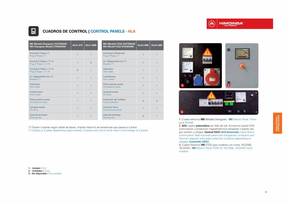
76
1. Cuadro eléctrico M0 (Modelo Triangular). M0 Electric Panel (Trian-
gular Model).
2. AC5 cuadro automático por fallo de red. Armario en pared CON
conmutación y protección magnetotérmica tetrapolar o bipolar (se-
gún tensión y voltaje). Central CEA7. AC5 Automatic mains failure
control panel. Wall mounted panel with changeover contactors and
thermal magnetic tetra polar protection or bipolar (depending on
voltage). Controller CEA7.
3. Cuadro Electrico M0 (TZ32 para modelos con motor 15LD350,
15LD440.). M0 Electric Panel (TZ32 for 15LD350, 15LD440 motor
models).
21
3
M0 (Modelo Triangular) ESTÁNDAR
M0 (Triangular Model) STANDARD HLA1 6T5 HLA1 5M5
Enchufe 2 Fases +TPlug 2 Phase +T
1 1
Enchufe 3 Fases + T+ NPlug 3 Phase + T+ N
1 X
Enchufe 2 Fases + T+ NPlug 2 Fases + T+ N
X 1
Int. Magnetotérmico (*)Breaker (*)
1 1
VoltímetroVolt meter
1 1
Amperímetro Amp meter
1 1
Piloto presión aceiteOil pressure lamp
1 1
Lámpara aceite Oil lamp
1 1
Llave de arranqueStarting key
1 1
MO (Modelo TZ32) ESTÁNDAR
MO (Model TZ32) STANDARD HLA3 4M5 HLA3 5M5
Interruptor Diferencial Plug 2 Phase +T
1 1
Int. Magnetotérmico (*)Breaker (*)
1 1
VoltímetroVolt meter
1 1
Cuentahoras Hour meter
1 1
Piloto presión aceiteOil pressure lamp
1 1
Lámpara aceite Oil lamp
1 1
Protección de Fusibles Fuse protection
2 2
Conexión tierraGround connection
1 1
Llave de arranqueStarting key
X 1
(*) Tripolar o bipolar según salida de bases. (tripolar hasta fin de existencias que pasará a 4 polos(*) 3 poles or 2 poles depending output sockets. (3 poles until end of stock when it will change to 4 poles)
CUADROS DE CONTROL | CONTROL PANELS · HLA
1 - Unidad / Unit2 - Unidades / UnitsX - No disponible / Not available
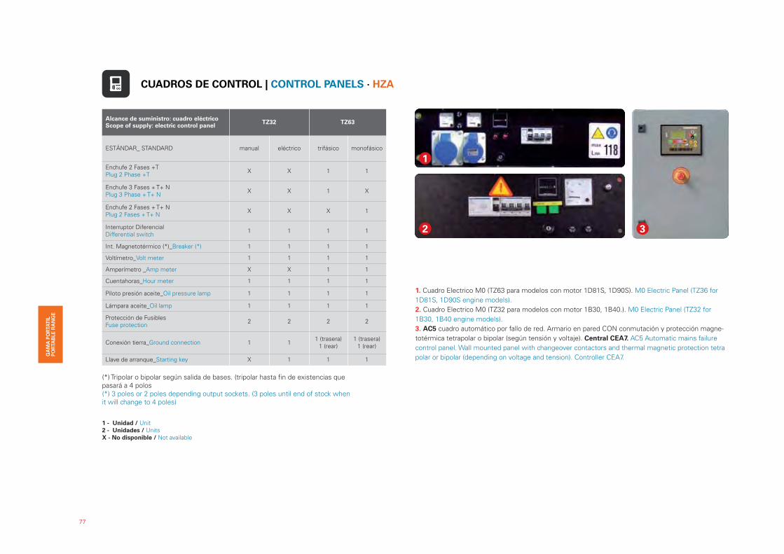
77
Alcance de suministro: cuadro eléctricoScope of supply: electric control panel
TZ32 TZ63
ESTÁNDAR_ STANDARD manual eléctrico trifásico monofásico
Enchufe 2 Fases +TPlug 2 Phase +T
X X 1 1
Enchufe 3 Fases + T+ NPlug 3 Phase + T+ N
X X 1 X
Enchufe 2 Fases + T+ NPlug 2 Fases + T+ N
X X X 1
Interruptor DiferencialDifferential switch
1 1 1 1
Int. Magnetotérmico (*)_Breaker (*) 1 1 1 1
Voltímetro_Volt meter 1 1 1 1
Amperímetro _Amp meter X X 1 1
Cuentahoras_Hour meter 1 1 1 1
Piloto presión aceite_Oil pressure lamp 1 1 1 1
Lámpara aceite_Oil lamp 1 1 1 1
Protección de Fusibles Fuse protection
2 2 2 2
Conexión tierra_Ground connection 1 11 (trasera)
1 (rear)1 (trasera)
1 (rear)
Llave de arranque_Starting key X 1 1 1
2 3
1
1. Cuadro Electrico M0 (TZ63 para modelos con motor 1D81S, 1D90S). M0 Electric Panel (TZ36 for
1D81S, 1D90S engine models).
2. Cuadro Electrico M0 (TZ32 para modelos con motor 1B30, 1B40.). M0 Electric Panel (TZ32 for
1B30, 1B40 engine models).
3. AC5 cuadro automático por fallo de red. Armario en pared CON conmutación y protección magne-
totérmica tetrapolar o bipolar (según tensión y voltaje). Central CEA7. AC5 Automatic mains failure
control panel. Wall mounted panel with changeover contactors and thermal magnetic protection tetra
polar or bipolar (depending on voltage and tension). Controller CEA7.
(*) Tripolar o bipolar según salida de bases. (tripolar hasta fin de existencias que pasará a 4 polos(*) 3 poles or 2 poles depending output sockets. (3 poles until end of stock when it will change to 4 poles)
CUADROS DE CONTROL | CONTROL PANELS · HZA
1 - Unidad / Unit2 - Unidades / UnitsX - No disponible / Not available
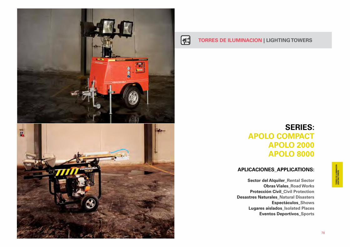
78
SERIES: APOLO COMPACT
APOLO 2000APOLO 8000
APLICACIONES_APPLICATIONS:
Sector del Alquiler_Rental Sector
Obras Viales_Road Works
Protección Civil_Civil Protection
Desastres Naturales_Natural Disasters
Espectáculos_Shows
Lugares aislados_Isolated Places
Eventos Deportivos_Sports
TORRES DE ILUMINACION | LIGHTING TOWERS
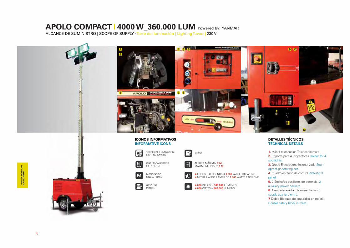
APOLO COMPACT � 4000 W_360.000 LUM Powered by: YANMARALCANCE DE SUMINISTRO | SCOPE OF SUPPLY · Torre de Iluminación | Lighting Tower | 230 V
79
1. Mástil telescópico.Telescopic mast.
2. Soporte para 4 Proyectores.Holder for 4
spotlights.
3. Grupo Electrógeno insonorizado.Soun-
dproof generating set.
4. Cuadro estanco de control.Watertight
panel.
5. 2 Enchufes auxiliares de potencia. 2
auxiliary power sockets.
6. 1 entrada auxiliar de alimentación. 1
supply auxiliary entry.
7. Doble Bloqueo de seguridad en mástil.
Double safety block in mast.
DETALLES TÉCNICOS
TECHNICAL DETAILS
ICONOS INFORMATIVOS
INFORMATIVE ICONS
GASOLINAPETROL
DIESEL
CINCUENTA HERZIOSFIFTY HERTZ
TORRES DE ILUMINACIONLIGHTING TOWERS
MONOFASICOSINGLE PHASE
4 FOCOS HALÓGENOS X 1.000 VATIOS CADA UNO. 4 METAL HALIDE LAMPS OF 1.000 WATTS EACH ONE.
ALTURA MÁXIMA: 9 M. MAXIMUM HEIGHT: 9 M.
4.000 VATIOS = 360.000 LÚMENES. 4.000 WATTS = 360.000 LUMENS.
1
2
3
4 5 6
7 8
9 10
7 8
12
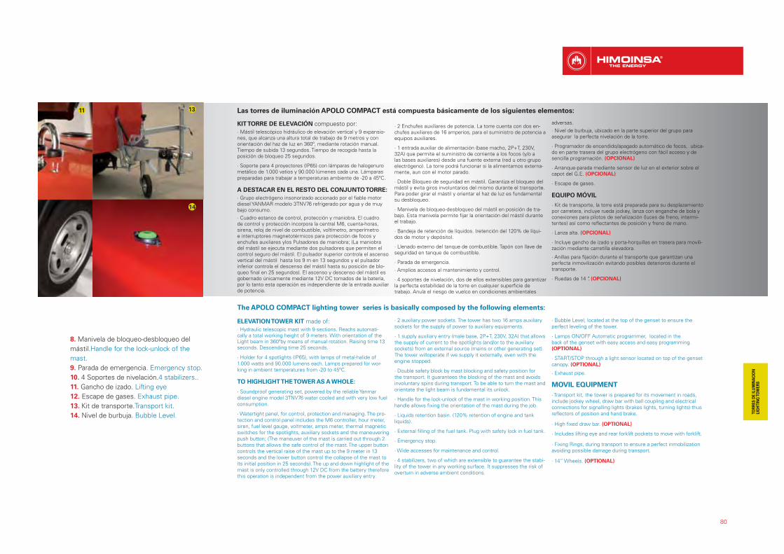
80
1311
14
The APOLO COMPACT lighting tower series is basically composed by the following elements:
ELEVATION TOWER KIT made of:
· Hydraulic telescopic mast with 9 sections. Reachs automati-cally a total working height of 9 meters. With orientation of the Light beam in 360ºby means of manual rotation. Raising time 13 seconds. Descending time 25 seconds.
· Holder for 4 spotlights (IP65), with lamps of metal-halide of 1.000 watts and 90.000 lumens each. Lamps prepared for wor-king in ambient temperatures from -20 to 45ºC.
TO HIGHLIGHT THE TOWER AS A WHOLE:
· Soundproof generating set, powered by the reliable Yanmar diesel engine model 3TNV76 water cooled and with very low fuel consumption.
· Watertight panel, for control, protection and managing. The pro-tection and control panel includes the M6 controller, hour meter, siren, fuel level gauge, voltmeter, amps meter, thermal magnetic switches for the spotlights, auxiliary sockets and the maneuvering push button; (The maneuver of the mast is carried out through 2 buttons that allows the safe control of the mast. The upper button controls the vertical raise of the mast up to the 9 meter in 13 seconds and the lower button control the collapse of the mast to its initial position in 25 seconds). The up and down highlight of the mast is only controlled through 12V DC from the battery therefore this operation is independent from the power auxiliary entry.
· 2 auxiliary power sockets. The tower has two 16 amps auxiliary sockets for the supply of power to auxiliary equipments.
· 1 supply auxiliary entry (male base, 2P+T, 230V, 32A) that allows the supply of current to the spotlights (and/or to the auxiliary sockets) from an external source (mains or other generating set). The tower willoperate if we supply it externally, even with the engine stopped.
· Double safety block by mast blocking and safety position for the transport. It guarantees the blocking of the mast and avoids involuntary spins during transport. To be able to turn the mast and orientate the light beam is fundamental its unlock.
· Handle for the lock-unlock of the mast in working position. This handle allows fixing the orientation of the mast during the job.
· Liquids retention basin. (120% retention of engine and tank liquids).
· External filling of the fuel tank. Plug with safety lock in fuel tank.
· Emergency stop.
· Wide accesses for maintenance and control.
· 4 stabilizers, two of which are extensible to guarantee the stabi-lity of the tower in any working surface. It suppresses the risk of overturn in adverse ambient conditions.
· Bubble Level, located at the top of the genset to ensure the perfect leveling of the tower.
· Lamps ON/OFF Automatic programmer, located in the back of the genset with easy access and easy programming. (OPTIONAL)
· START/STOP through a light sensor located on top of the genset canopy. (OPTIONAL)
· Exhaust pipe.
MOVIL EQUIPMENT
· Transport kit, the tower is prepared for its movement in roads, include jockey wheel, draw bar with ball coupling and electrical connections for signalling lights (brakes lights, turning lights) thus reflectors of position and hand brake.
· High fixed draw bar. (OPTIONAL)
· Includes lifting eye and rear forklift pockets to move with forklift.
· Fixing Rings, during transport to ensure a perfect inmobilization avoiding possible damage during transport.
· 14” Wheels. (OPTIONAL)
8. Manivela de bloqueo-desbloqueo del
mástil.Handle for the lock-unlock of the
mast.
9. Parada de emergencia. Emergency stop.
10. 4 Soportes de nivelación.4 stabilizers..
11. Gancho de izado. Lifting eye
12. Escape de gases. Exhaust pipe.
13. Kit de transporte.Transport kit.
14. Nivel de burbuja. Bubble Level.
Las torres de iluminación APOLO COMPACT está compuesta básicamente de los siguientes elementos:
KIT TORRE DE ELEVACIÓN compuesto por:
· Mástil telescópico hidráulico de elevación vertical y 9 expansio-nes, que alcanza una altura total de trabajo de 9 metros y con orientación del haz de luz en 360º, mediante rotación manual. Tiempo de subida 13 segundos. Tiempo de recogida hasta la posición de bloqueo 25 segundos.
· Soporte para 4 proyectores (IP65) con lámparas de halogenuro metálico de 1.000 vatios y 90.000 lúmenes cada una. Lámparas preparadas para trabajar a temperaturas ambiente de -20 a 45ºC.
A DESTACAR EN EL RESTO DEL CONJUNTO TORRE:
· Grupo electrógeno insonorizado accionado por el fiable motor diesel YANMAR modelo 3TNV76 refrigerado por agua y de muy bajo consumo.
· Cuadro estanco de control, protección y maniobra. El cuadro de control y protección incorpora la central M6, cuenta-horas, sirena, reloj de nivel de combustible, voltímetro, amperímetro e interruptores magnetotérmicos para protección de focos y enchufes auxiliares ylos Pulsadores de maniobra; (La maniobra del mástil se ejecuta mediante dos pulsadores que permiten el control seguro del mástil. El pulsador superior controla el ascenso vertical del mástil hasta los 9 m en 13 segundos y el pulsador inferior controla el descenso del mástil hasta su posición de blo-queo final en 25 segundos). El ascenso y descenso del mástil es gobernado únicamente mediante 12V DC tomados de la batería, por lo tanto esta operación es independiente de la entrada auxiliar de potencia.
· 2 Enchufes auxiliares de potencia. La torre cuenta con dos en-chufes auxiliares de 16 amperios, para el suministro de potencia a equipos auxiliares.
· 1 entrada auxiliar de alimentación (base macho, 2P+T, 230V, 32A) que permite el suministro de corriente a los focos (y/o a las bases auxiliares) desde una fuente externa (red u otro grupo electrógeno). La torre podrá funcionar si la alimentamos externa-mente, aun con el motor parado.
· Doble Bloqueo de seguridad en mástil. Garantiza el bloqueo del mástil y evita giros involuntarios del mismo durante el transporte. Para poder girar el mástil y orientar el haz de luz es fundamental su desbloqueo.
· Manivela de bloqueo-desbloqueo del mástil en posición de tra-bajo. Esta manivela permite fijar la orientación del mástil durante el trabajo.
· Bandeja de retención de líquidos. (retención del 120% de líqui-dos de motor y depósito).
· Llenado externo del tanque de combustible. Tapón con llave de seguridad en tanque de combustible.
· Parada de emergencia.
· Amplios accesos al mantenimiento y control.
· 4 soportes de nivelación, dos de ellos extensibles para garantizar la perfecta estabilidad de la torre en cualquier superficie de trabajo. Anula el riesgo de vuelco en condiciones ambientales
adversas.
· Nivel de burbuja, ubicado en la parte superior del grupo para asegurar la perfecta nivelación de la torre.
· Programador de encendido/apagado automático de focos, ubica-do en parte trasera del grupo electrógeno con fácil acceso y de sencilla programación. (OPCIONAL)
· Arranque-parada mediante sensor de luz en el exterior sobre el capot del G.E. (OPCIONAL)
· Escape de gases.
EQUIPO MÓVIL
· Kit de transporte, la torre está preparada para su desplazamiento por carretera, incluye rueda jockey, lanza con enganche de bola y conexiones para pilotos de señalización (luces de freno, intermi-tentes) así como reflectantes de posición y freno de mano.
· Lanza alta. (OPCIONAL)
· Incluye gancho de izado y porta-horquillas en trasera para movili-zación mediante carretilla elevadora.
· Anillas para fijación durante el transporte que garantizan una perfecta inmovilización evitando posibles deterioros durante el transporte.
· Ruedas de 14 “. (OPCIONAL)

Modelo TORRE APOLO COMPACT
Mobile lighting tower model HTYW 7 M5
Potencia P.R.P._Power P.R.P. kVA / kW 6,4 / 6,4
Frecuencia_Frequency Hz 50
Voltaje_Voltage V 230
Dimensiones Máximas_mm. (en posición de trabajo) Maximum Dimensions_mm. (working position)
L x W x H 2.220 X 2.450 X 9.000
Dimensiones Mínimas (en modo transporte)Minimum Dimensions (transport mode)
L x W x H 2.220 X 1.260 X 2.200
Peso en seco_Dry weight (unfuelled) Kg 911
Combustible_Fuel Diesel
Capacidad del tanque_Fuel tank capacity L 100
Llenado del tanque_Tank refilling externo/external
Autonomía_Autonomy Hr. 50
Nivel de ruido_Sound Level 90LWA - 65dB(A)
MOTOR | ENGINE
Modelo_Model YANMAR - 3TNV76
Nº Cilindros y ubicación_Cylindres nº & position 3 L
Aspiración_Aspiration Natural
Régimen de funcionamiento_Rated Speed r.p.m 1500
Sistema de refrigeración_Cooling system Líquido refrigerante / Cooling system
Consumo de combustible_Fuel consumption L/hr. 1,98
Regulador_Speed governor Mecánico / Mechanical
ALTERNADOR | ALTERNATOR
Nº polos alternador_Alternator poles nº 4 Pol., 230V, 50Hz
Regulador de tensión_Voltage regulator AVR
MASTIL | MAST
Tipo de Mástil_Mast Type Hidráulico / Hydraulic
Secciones del Mástil_Mast Sections 9
Tiempo de subida / bajada_Erecting / Collapsing time 13 sec. / 25 sec.
Rotación_Rotation 360º (manual)
Doble bloque de seguridad_Double safety block Standard
Nº de focos_Spotlights nº 4 x 1000 W
Tipo de focos_Spotlights type Halogenuro metálico / Metal halide
Lúmenes totales_Total lumens 4 x 90.000 = 360.000
CARROCERÍA | CANOPY
Capot insonorizado_Soundproof canopy Standard
Bandeja de retención_Liquids retention basin120% Líquidos motor y depósito
120% Liquids retention (engine&tank)
Enchufes auxiliares_Auxiliary sockets 2 x 16Amp. 230V
Entrada auxiliar de alimentaciónAuxiliary input supply socket
1 x 32 Amp. 230V
Gancho de izado_Lifting eye Standard
CHASIS | CHASSIS
Kit de tracción del chasis_Chassis traction kit Standard
Pilotos de señalización_Road lights and reflectors Standard
Ruedas_Wheels 2 x 185/70R 13
Estabilizadores_Stabilisers 4
Porta-horquillas_Forklifts pockets Standard
CUADRO | CONTROL PANEL
Central de control y protecciónControl and protection controller
Central manual M6 / M6 manual controller
Cuenta-horas, sirena,reloj de nivel de combustible, voltímetro, amperímetro e interruptores magnetotérmicos para protección de focos y enchufes auxiliares
Estándar / Standard
Hour meter, siren, fuel level gauge, voltmeter, amps meter, thermal magnetic switches for the spot-lights and auxiliary sockets
Pulsadores de maniobra_Maneuvering push buttons 2 (1xascenso, 1xdescenso) (1xrising, 1xdescending)
81
DATOS TÉCNICOS | TECHNICAL DATA · APOLO COMPACTD

82
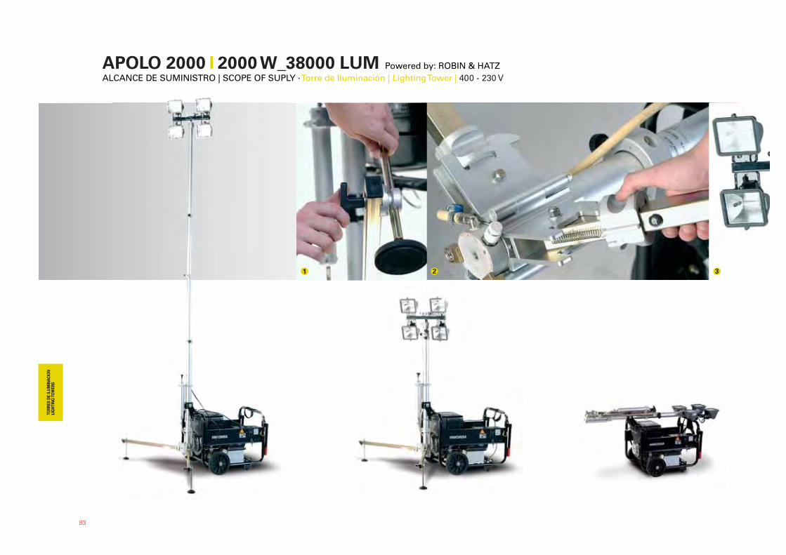
APOLO 2000 �� 2000 W_38000 LUM Powered by: ROBIN & HATZALCANCE DE SUMINISTRO | SCOPE OF SUPLY · Torre de Iluminación | Lighting Tower | 400 - 230 V
1 2 3
83

1. Pie nivelador. Levelling Feet.
2. Anillos de Fijación. Rings of Fixing.
3. 4 Proyectores. Four Projectors.
4. Valvula de Presión. Air Outlet Valve.
4
84
Las torres de iluminación de la serie APOLO 2000 se componen básicamente de los siguientes elementos:
KIT TORRE DE ELEVACIÓN compuesto por:
· Mástil telescópico con bomba neumática de accionamiento manual, que desplegado alcanza los 4,6 metros de altura y permite un giro ma-nual de 360º. 2 Soportes de nivelación abatibles para garantizar la perfecta estabilidad de la torre en cualquier tipo de superficie.
· Soporte para lámparas halógenas.4 Proyecto-res halógenos de 500 vatios con 9.500 lúmenes cada uno. GRUPO ELECTRÓGENO MÓVIL
· Los grupos electrógenos HIMOINSA a instalar de estándar en la serie 2000, son grupos de reducido tamaño, lo que garantiza una perfecta movilidad en cualquier lugar. Accionados por motor HIMOINSA o HATZ, la gama de potencia varía desde las 5 kVA hasta las 7 kVA a 3.000 r.p.m., estando disponible en tensiones monofá-sicas y trifásicas.
SOPORTE DE PROYECTORES
· Comprende 4 proyectores robustos y compac-tos (IP55), con lámparas de cuarzo-yodo de 500 vatios y 9.500 lúmenes cada una. Cada una de las secciones del mástil está bloqueada por un mecanismo de cierre por presión, que permite según el sentido de giro el ascenso o descenso del tramo de mástil correspondiente.
MASTIL TELESCÓPICO
· De aluminio compuesto de tres tramos que izado en su totalidad alcanza una altura de 4,5m. Antes del bloqueo del último tramo, se puede girar el mástil manualmente hasta 360º para conseguir una buena orientación del haz de luz.
BOMBA NEUMÁTICA
· El mástil incorpora bomba neumática de accionamiento manual para la elevación de sus tres secciones.
2 SOPORTES DE NIVELACIÓN
· Para garantizar la perfecta estabilidad de la to-rre en cualquier tipo de superficie. Son abatibles
y quedan bloqueados y asegurados por los ani-llos de fijación. Estos soportes incorporan unos pies niveladores que garantizan la estabilidad y fortaleza del mástil, de forma que este sea totalmente perpendicular con el suelo.
HORQUILLA DE SEGURIDAD
· La bancada del grupo electrógeno incorpora una horquilla para fijar el mástil y evitar caídas accidentales del mismo durante su trabajo.
VALVULA DE PRESIÓN
· Permite bloquear el aire en el interior del mástil durante su elevación o bien el descenso del mismo con su apertura.
GRUPO ELECTRÓGENO MÓVIL
· El grupos electrógeno incorpora ruedas y asi-deras para su desplazamiento, así como la base para la conexión del enchufe que dará corriente a los focos.
ICONOS INFORMATIVOS
INFORMATIVE ICONS
GASOLINAPETROL
DIESEL
CINCUENTA HERZIOSFIFTY HERTZ
TORRES DE ILUMINACIONLIGHTING TOWERS
MONOFASICOSINGLE PHASE
4 FOCOS HALÓGENOS X 500 VATIOS CADA UNO. 4 METAL HALIDE LAMPS OF 500 WATTS EACH ONE.
ALTURA MÁXIMA: 4,6 M. MAXIMUM HEIGHT: 4,6 M.
2.000 VATIOS = 38.000 LÚMENES. 2.000 WATTS = 38.000 LUMENS.
The APOLO 2000 series are basically composed by the following elements:
ELEVATION KIT mainly composed by:
· Telescopic mast with manually-operated pneu-matic pump which reaches 4.6 meters of height and 360° of manual rotation.2 Levelling supports to guarantee the perfect stability of the tower in any surface.
· Halogenous lamps Supports.4 Halogenous projectors of 500-watts and 9.500 lumens each one.
MOBILE GENERATING SET
· The HIMOINSA generating sets installed as standard in the Series 2000, are very compact which guarantee its perfect mobility in any type of surface. Powered by HATZ and HIMOINSA engines, with a power range from 5 kVA up to 7 kVA at 3.000 r.p.m., being available for either in single or three phase voltage.
PROYECTORS SUPPORT
· Compose of 4 compact and robust projectors (IP55), with quartz-iodine lamps of 500 watts
and 9500 lumens each one. Each section of the mast is blocked for a wheel of pressure, that permits according to the sense of turning, the ascent or descent of the correspondent section of mast.
TELESCOPIC MAST
· Of aluminium fixed of three sections than pulled up completely attains a height of 4,5m. Before the blockage of the latter section, the mast can be turn manually 360º to get a good orientation of the bundle of light.
PNEUMATIC PUMP
· The mast includes a manually-operated pneumatic pump for the elevation of its three sections.
2 LEVELING SUPPORTS
· In order to guarantee the perfect stability of the tower in any fellow of surface. They are fol-ding and they become blocked and insured for the rings of fixing. These supports incorporate
some levelling feet that guarantee the stability and the mast’s fortress, as well as is totally perpendicular SFA with the ground.
SAFETY PITCHFORK
· The generating sets frame incorporates a pitchfork to fix the mast and to avoid accidental falls during its work.
AIR OUTLET VALVE
· It permits blocking the air inside of the mast during his elevation or else the descent with his opening.
MOBILE GENERATING SET
· The generating set incorporates wheels and handles for its displacement, the same way that a base for the connection of the socket that it will give current to the spotlights.
DETALLES TÉCNICOS
TECHNICAL DETAILS
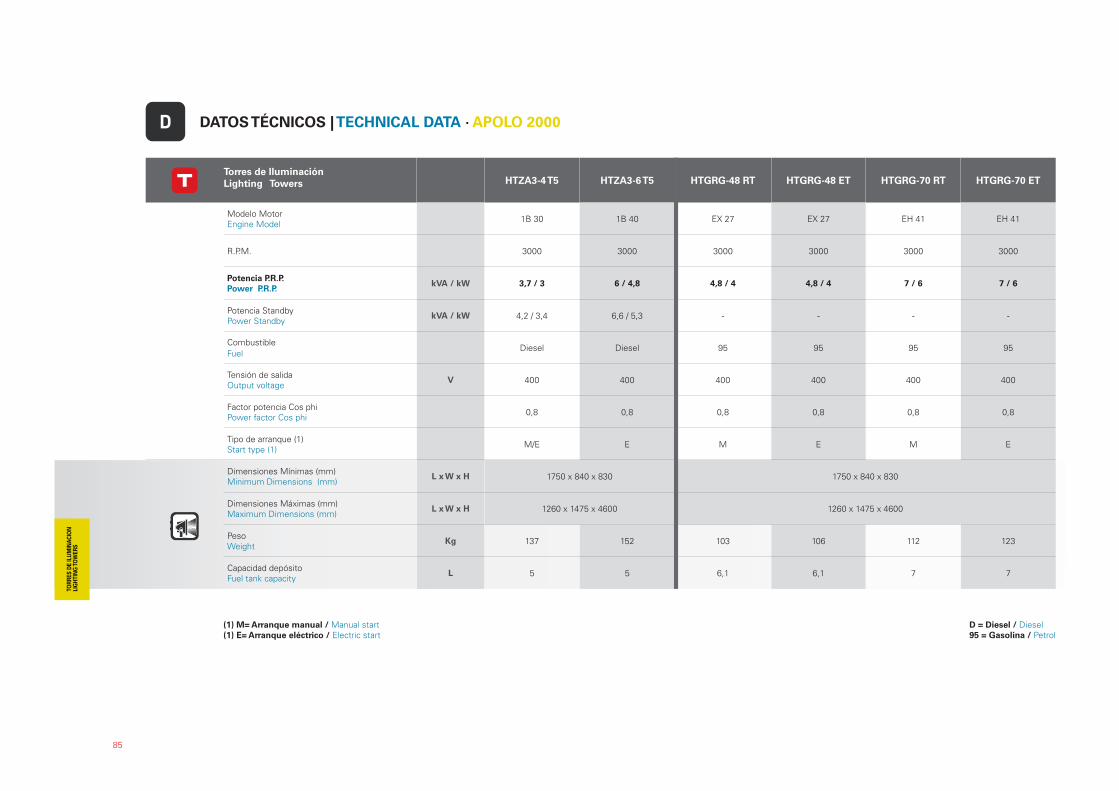
85
Torres de Iluminación
Lighting Towers HTZA3-4 T5 HTZA3-6 T5 HTGRG-48 RT HTGRG-48 ET HTGRG-70 RT HTGRG-70 ET
Modelo Motor Engine Model
1B 30 1B 40 EX 27 EX 27 EH 41 EH 41
R.P.M. 3000 3000 3000 3000 3000 3000
Potencia P.R.P.
Power P.R.P. kVA / kW 3,7 / 3 6 / 4,8 4,8 / 4 4,8 / 4 7 / 6 7 / 6
Potencia StandbyPower Standby
kVA / kW 4,2 / 3,4 6,6 / 5,3 - - - -
Combustible
FuelDiesel Diesel 95 95 95 95
Tensión de salida Output voltage
V 400 400 400 400 400 400
Factor potencia Cos phiPower factor Cos phi
0,8 0,8 0,8 0,8 0,8 0,8
Tipo de arranque (1)Start type (1)
M/E E M E M E
Dimensiones Mínimas (mm)Minimum Dimensions (mm)
L x W x H 1750 x 840 x 830 1750 x 840 x 830
Dimensiones Máximas (mm)Maximum Dimensions (mm)
L x W x H 1260 x 1475 x 4600 1260 x 1475 x 4600
PesoWeight
Kg 137 152 103 106 112 123
Capacidad depósitoFuel tank capacity
L 5 5 6,1 6,1 7 7
DATOS TÉCNICOS | TECHNICAL DATA · APOLO 2000D
(1) M= Arranque manual / Manual start(1) E= Arranque eléctrico / Electric start
D = Diesel / Diesel 95 = Gasolina / Petrol
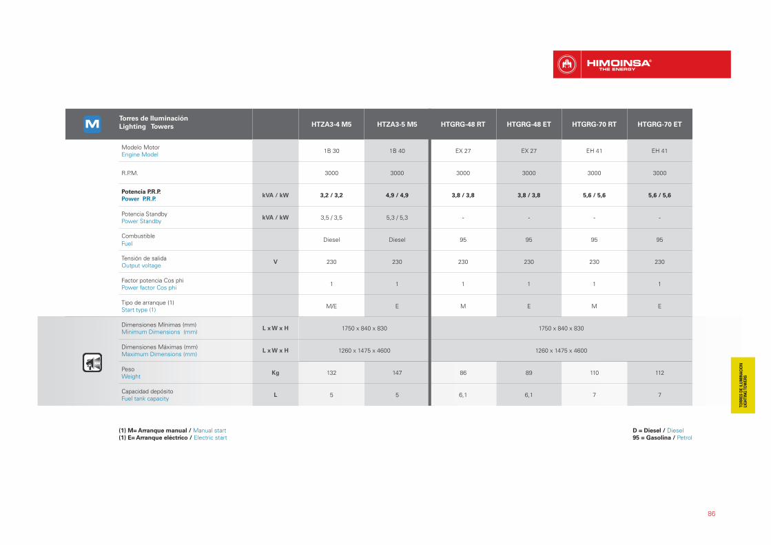
86
Torres de Iluminación
Lighting Towers HTZA3-4 M5 HTZA3-5 M5 HTGRG-48 RT HTGRG-48 ET HTGRG-70 RT HTGRG-70 ET
Modelo Motor Engine Model
1B 30 1B 40 EX 27 EX 27 EH 41 EH 41
R.P.M. 3000 3000 3000 3000 3000 3000
Potencia P.R.P.
Power P.R.P. kVA / kW 3,2 / 3,2 4,9 / 4,9 3,8 / 3,8 3,8 / 3,8 5,6 / 5,6 5,6 / 5,6
Potencia StandbyPower Standby
kVA / kW 3,5 / 3,5 5,3 / 5,3 - - - -
Combustible
FuelDiesel Diesel 95 95 95 95
Tensión de salida Output voltage
V 230 230 230 230 230 230
Factor potencia Cos phiPower factor Cos phi
1 1 1 1 1 1
Tipo de arranque (1)Start type (1)
M/E E M E M E
Dimensiones Mínimas (mm)Minimum Dimensions (mm)
L x W x H 1750 x 840 x 830 1750 x 840 x 830
Dimensiones Máximas (mm)Maximum Dimensions (mm)
L x W x H 1260 x 1475 x 4600 1260 x 1475 x 4600
PesoWeight
Kg 132 147 86 89 110 112
Capacidad depósitoFuel tank capacity
L 5 5 6,1 6,1 7 7
(1) M= Arranque manual / Manual start(1) E= Arranque eléctrico / Electric start
D = Diesel / Diesel 95 = Gasolina / Petrol
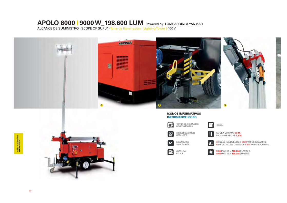
APOLO 8000 �� 9000 W_198.600 LUM Powered by: LOMBARDINI & YANMARALCANCE DE SUMINISTRO | SCOPE OF SUPLY · Torre de Iluminación | Lighting Tower | 400 V
87
1 2 3
ICONOS INFORMATIVOS
INFORMATIVE ICONS
GASOLINAPETROL
DIESEL
CINCUENTA HERZIOSFIFTY HERTZ
TORRES DE ILUMINACIONLIGHTING TOWERS
MONOFASICOSINGLE PHASE
6 FOCOS HALÓGENOS X 1.500 VATIOS CADA UNO. 6 METAL HALIDE LAMPS OF 1.500 WATTS EACH ONE.
ALTURA MÁXIMA: 8,9 M. MAXIMUM HEIGHT: 8,9 M.
9.000 VATIOS = 198.000 LÚMENES. 9.000 WATTS = 198.000 LUMENS.
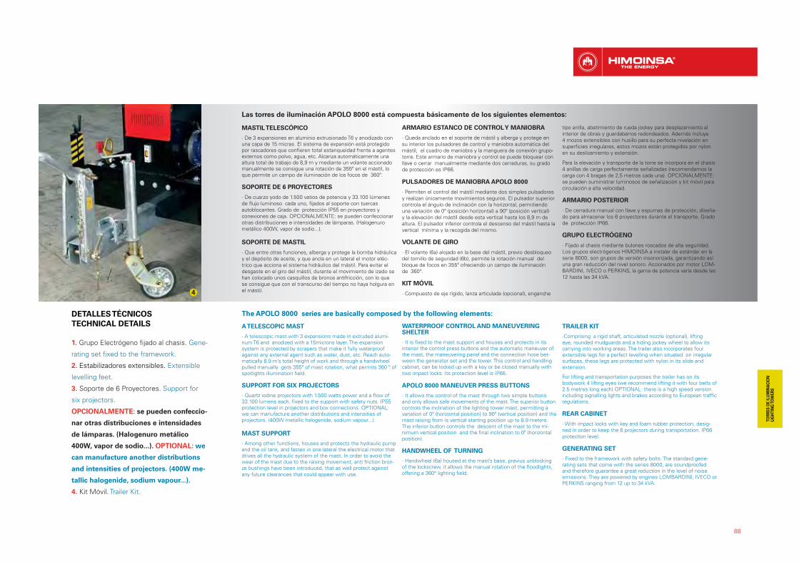
88
Las torres de iluminación APOLO 8000 está compuesta básicamente de los siguientes elementos:
MASTIL TELESCÓPICO
· De 3 expansiones en aluminio extrusionado T6 y anodizado con una capa de 15 micras. El sistema de expansión está protegido por rascadores que confieren total estanqueidad frente a agentes externos como polvo, agua, etc. Alcanza automáticamente una altura total de trabajo de 8,9 m y mediante un volante accionado manualmente se consigue una rotación de 355º en el mástil, lo que permite un campo de iluminación de los focos de 360º.
SOPORTE DE 6 PROYECTORES
· De cuarzo yodo de 1.500 vatios de potencia y 33.100 lúmenes de flujo luminoso cada uno, fijados al soporte con tuercas autoblocantes. Grado de protección IP55 en proyectores y conexiones de caja. OPCIONALMENTE: se pueden confeccionar otras distribuciones e intensidades de lámparas. (Halogenuro metálico 400W, vapor de sodio...).
SOPORTE DE MASTIL
· Que entre otras funciones, alberga y protege la bomba hidráulica y el depósito de aceite, y que ancla en un lateral el motor eléc-trico que acciona el sistema hidráulico del mástil. Para evitar el desgaste en el giro del mástil, durante el movimiento de izado se han colocado unos casquillos de bronce antifricción, con lo que se consigue que con el transcurso del tiempo no haya holgura en el mástil.
ARMARIO ESTANCO DE CONTROL Y MANIOBRA
· Queda anclado en el soporte de mástil y alberga y protege en su interior los pulsadores de control y maniobra automática del mástil, el cuadro de maniobra y la manguera de conexión grupo-torre. Este armario de maniobra y control se puede bloquear con llave o cerrar manualmente mediante dos cerraduras, su grado de protección es IP66.
PULSADORES DE MANIOBRA APOLO 8000
· Permiten el control del mástil mediante dos simples pulsadores y realizan únicamente movimientos seguros. El pulsador superior controla el ángulo de inclinación con la horizontal, permitiendo una variación de 0º (posición horizontal) a 90º (posición vertical) y la elevación del mástil desde esta vertical hasta los 8,9 m de altura. El pulsador inferior controla el descenso del mástil hasta la vertical mínima y la recogida del mismo.
VOLANTE DE GIRO
· El volante (6a) alojado en la base del mástil, previo desbloqueo del tornillo de seguridad (6b), permite la rotación manual del bloque de focos en 355º ofreciendo un campo de iluminación de 360°.
KIT MÓVIL
· Compuesto de eje rígido, lanza articulada (opcional), enganche
tipo anilla, abatimiento de rueda jockey para desplazamiento al interior de obras y guardabarros redondeados. Además incluye 4 mozos extensibles con husillo para su perfecta nivelación en superficies irregulares, estos mozos están protegidos por nylon en su deslizamiento y extensión.
Para la elevación y transporte de la torre se incorpora en el chasis 4 anillas de carga perfectamente señalizadas (recomendamos la carga con 4 bragas de 2,5 metros cada una). OPCIONALMENTE: se pueden suministrar luminosos de señalización y kit móvil para circulación a alta velocidad.
ARMARIO POSTERIOR
· De cerradura manual con llave y espumas de protección, diseña-do para almacenar los 6 proyectores durante el transporte. Grado de protección IP66.
GRUPO ELECTRÓGENO
· Fijado al chasis mediante bulones roscados de alta seguridad. Los grupos electrógenos HIMOINSA a instalar de estándar en la serie 8000, son grupos de versión insonorizada, garantizando así una gran reducción del nivel sonoro. Accionados por motor LOM-BARDINI, IVECO o PERKINS, la gama de potencia varía desde las 12 hasta las 34 kVA.
The APOLO 8000 series are basically composed by the following elements:
A TELESCOPIC MAST
· A telescopic mast with 3 expansions made in extruded alumi-num T6 and anodized with a 15microns layer. The expansion system is protected by scrapers that make it fully waterproof against any external agent such as water, dust, etc. Reach auto-matically 8.9 m’s total height of work and through a handwheel pulled manually gets 355º of mast rotation, what permits 360 º of spotlights illumination field.
SUPPORT FOR SIX PROJECTORS
· Quartz iodine projectors with 1.500 watts power and a flow of 33.100 lumens each, fixed to the support with safety nuts. IP55 protection level in projectors and box connections. OPTIONAL: we can manufacture another distributions and intensities of projectors. (400W metallic halogenide, sodium vapour...).
MAST SUPPORT
· Among other functions, houses and protects the hydraulic pump and the oil tank, and fasten in one lateral the electrical motor that drives all the hydraulic system of the mast. In order to avoid the wear of the mast due to the raising movement, anti friction bron-ze bushings have been introduced, that as well protect against any future clearances that could appear with use.
WATERPROOF CONTROL AND MANEUVERING SHELTER
· It is fixed to the mast support and houses and protects in its interior the control press buttons and the automatic maneuver of the mast, the maneuvering panel and the connection hose bet-ween the generator set and the tower. This control and handling cabinet, can be locked up with a key or be closed manually with two impact locks. Its protection level is IP66.
APOLO 8000 MANEUVER PRESS BUTTONS
· It allows the control of the mast through two simple buttons and only allows safe movements of the mast. The superior button controls the inclination of the lighting tower mast, permitting a variation of 0º (horizontal position) to 90º (vertical position) and the mast raising from is vertical starting position up to 8.9 meters. The inferior button controls the descent of the mast to the mi-nimum vertical position and the final inclination to 0º (horizontal position).
HANDWHEEL OF TURNING
· Handwheel (6a) housed at the mast’s base, previus unblocking of the lockscrew, it allows the manual rotation of the floodlights, offering a 360° lighting field.
TRAILER KIT
·Comprising a rigid shaft, articulated nozzle (optional), lifting eye, rounded mudguards and a hiding jockey wheel to allow its carrying into working areas. The trailer also incorporates four extensible legs for a perfect levelling when situated on irregular surfaces, these legs are protected with nylon in its slide and extension.
For lifting and transportation purposes the trailer has on its bodywork 4 lifting eyes (we recommend lifting it with four belts of 2.5 metres long each).OPTIONAL: there is a high speed version including signalling lights and brakes according to European traffic regulations.
REAR CABINET
· With impact locks with key and foam rubber protection, desig-ned in order to keep the 6 projectors during transportation. IP66 protection level.
GENERATING SET
· Fixed to the framework with safety bolts. The standard gene-rating sets that come with the series 8000, are soundproofed and therefore guarantee a great reduction in the level of noise emissions. They are powered by engines LOMBARDINI, IVECO or PERKINS ranging from 12 up to 34 kVA.
1. Grupo Electrógeno fijado al chasis. Gene-
rating set fixed to the framework.
2. Estabilizadores extensibles. Extensible
levelling feet.
3. Soporte de 6 Proyectores. Support for
six projectors.
OPCIONALMENTE: se pueden confeccio-
nar otras distribuciones e intensidades
de lámparas. (Halogenuro metálico
400W, vapor de sodio...). OPTIONAL: we
can manufacture another distributions
and intensities of projectors. (400W me-
tallic halogenide, sodium vapour...).
4. Kit Móvil. Trailer Kit.
DETALLES TÉCNICOS
TECHNICAL DETAILS
4

89
Torres de Iluminación
Lighting TowersHTYW-17 T5 HTYW-20 T5 HTYW-35 T5
Marca Motor
Engine BrandYanmar Yanmar Yanmar
Modelo Motor Engine Model
4TNV88 4TNV84T 4TNV98
R.P.M. 1500 1500 1500
Potencia P.R.P.
Power P.R.P. kVA / kW 17 / 13,7 20 / 16 34 / 27
Potencia StandbyPower Standby
kVA / kW 18 / 14,6 22 / 18 37 / 30
Norma 97/68/EC
Tensión de salida Output voltage
V 400 400 400
Factor potencia Cos phiPower factor Cos phi
0,8 0,8 0,8
Dimensiones Mínimas (mm)Minimum Dimensions (mm)
L x W x H 3700 x 1570 x 2160
Dimensiones Máximas (mm)Maximum Dimensions (mm)
L x W x H 4000 x 3100 x 9410
PesoWeight
Kg 1901 1920 2105
Capacidad depósitoFuel tank capacity
L 38 38 60
DATOS TÉCNICOS | TECHNICAL DATA · APOLO 8000D
No exigible / Not applicable Cumple con la directiva 97/68/EC (Stage II) / According to directive 97/68/EC (Stage II) No cumple con la directiva 97/68/EC (Stage II) / Not according to directive 97/68/EC (Stage II)

CUADROS DE CONTROL Y POTENCIACONTROL AND POWER PANELS:
GAMA PROFESIONAL_PROFESSIONAL RANGE
90
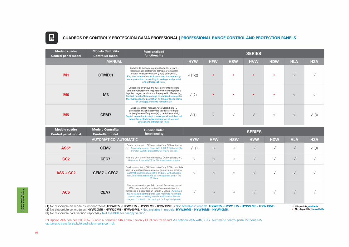
91
Modelo cuadro
Control panel model
Modelo Centralita
Controller model
Funcionalidad
functionality SERIES
MANUAL HYW HFW HSW HVW HDW HLA HZA
M1 CTME01
Cuadro de arranque manual por llave y pro-tección magnetotérmica tetrapolar o bipolar (según tensión y voltaje) y relé diferencial_
Key start manual control panel and thermal mag-netic protection (according to voltage and phase)
and differential relay.
� (1-2) • • • • � �
M6 M6
Cuadro de arranque manual por contacto libre tensión y protección magnetotérmica tetrapolar o bipolar (según tensión y voltaje) y relé diferencial_ Control panel of free voltage contactand tetra polar thermal magnetic protection or bipolar (depending
on voltage) and diffe-rential relay.
� (2) • • • • � �
M5 CEM7
Cuadro control manual Auto-Start digital y protección magnetotérmica tetrapolar o bipo-lar (según tensión y voltaje) y relé diferencial_
Digital manual auto-start control panel and thermal magnetic protection (according to voltage and
phase) and differential relay.
��(1) �� �� � � � ��(3)
Modelo cuadro
Control panel model
Modelo Centralita
Controller model
Funcionalidad
functionality SERIES
AUTOMÁTICO_AUTOMATIC HYW HFW HSW HVW HDW HLA HZA
AS5* CEM7Cuadro automático SIN conmutación y SIN control de
red_ Automatic control panel WITHOUT ATS (Automatic Transfer Switch) and WITHOUT mains control.
��(1) �� �� � � � ��(3)
CC2 CEC7Armario de Conmutación Himoinsa CON visualización_
Himoinsa External ATS WiITH visualization display. � � � � � � �
AS5 + CC2 CEM7 + CEC7
Cuadro automático CON conmutación y CON control de red. La visualización estará en el grupo y en el armario. Automatic with mains control and ATS with visualiza-tion. The visualization will be in the genset and in the
ATS box.
�� �� �� �� �� �� ��
AC5 CEA7
Cuadro automático por fallo de red. Armario en pared CON conmutación y protección magnetotérmica
tetrapolar o bipolar (según tensión y voltaje_Automatic Mains Failure control panel. Wall mounted Automatic control panel including transfer switch with thermal
magnetic protection (according to voltage and phase).
� � � � � � �
CUADROS DE CONTROL Y PROTECCIÓN GAMA PROFESIONAL | PROFESSIONAL RANGE CONTROL AND PROTECTION PANELS
(1) No disponible en modelos insonorizados: HYW8T5 - HYW13T5 - HYW9 M5 - HYW13M5. / Not available in models: HYW8T5 - HYW13T5 - HYW9 M5 - HYW13M5.(2) No disponible en modelos: HYW20M5 - HYW30M5 - HYW40M5. / Not available in models: HYW20M5 - HYW30M5 - HYW40M5.(3) No disponible para versión capotada / Not available for canopy version.
(*) Opción AS5 con central CEA7. Cuadro automático SIN conmutación y CON control de red. As optional AS5 with CEA7 Automatic control panel without ATS(automatic transfer switch) and with mains control.
� Disponible_Available• No disponible_Unavailable
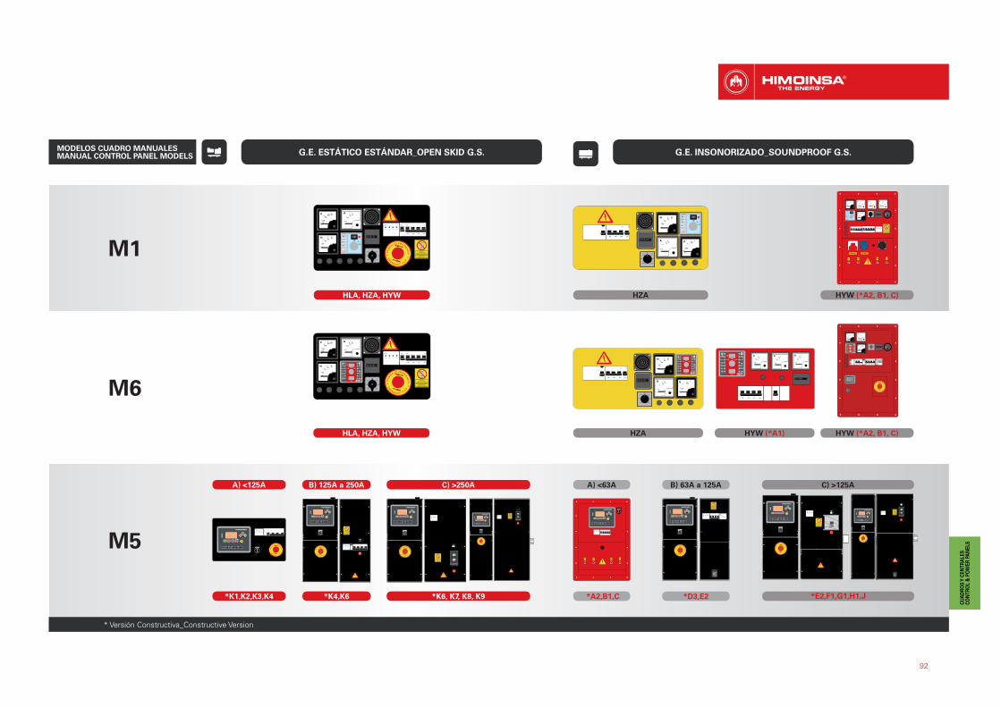
92
G.E. ESTÁTICO ESTÁNDAR_OPEN SKID G.S. G.E. INSONORIZADO_SOUNDPROOF G.S.
M1
M6
HZAHLA, HZA, HYW
HLA, HZA, HYW HZA HYW (*A1) HYW (*A2, B1, C)
HYW (*A2, B1, C)
M5
A) <125A
*K1,K2,K3,K4
B) 125A a 250A
*K4,K6
C) >250A
*K6, K7, K8, K9 *A2,B1,C
A) <63A
*D3,E2
B) 63A a 125A
*E2,F1,G1,H1,J
C) >125A
MODELOS CUADRO MANUALES MANUAL CONTROL PANEL MODELS
* Versión Constructiva_Constructive Version
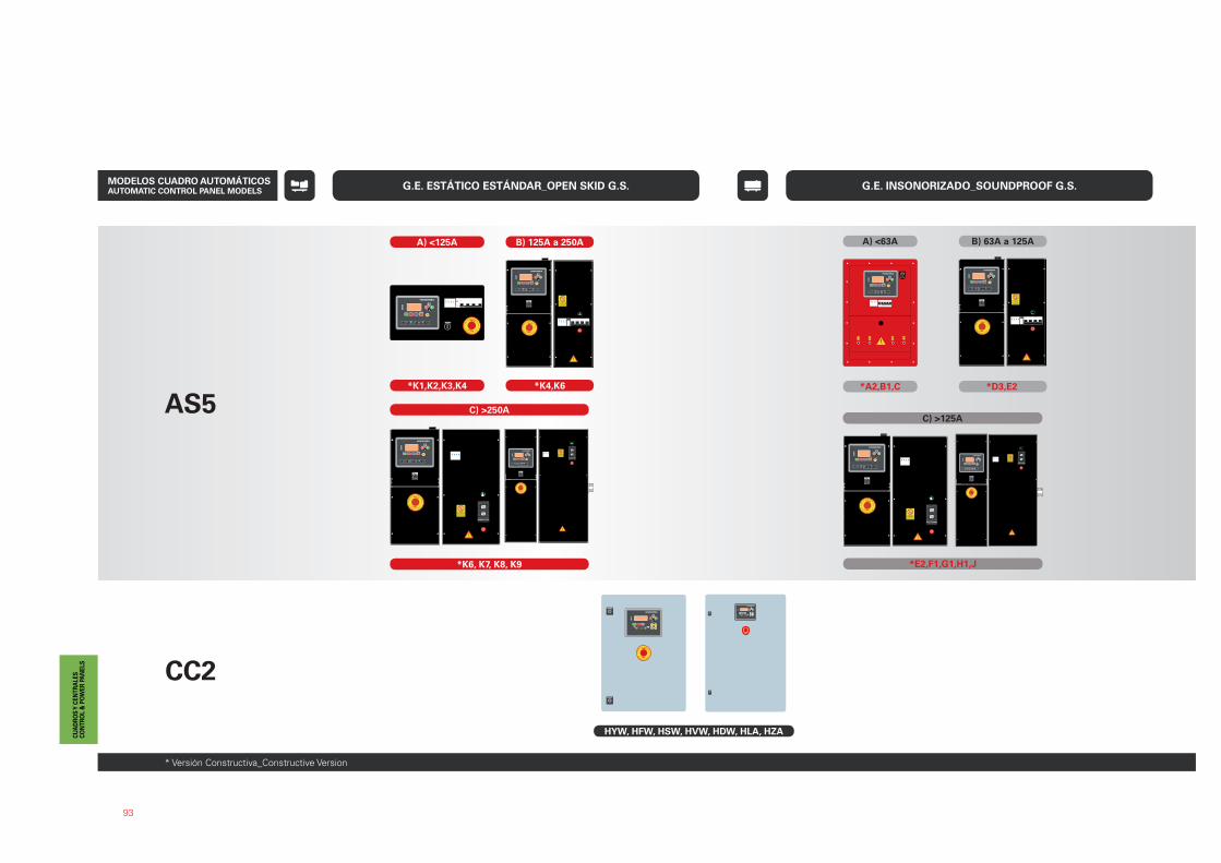
93
G.E. ESTÁTICO ESTÁNDAR_OPEN SKID G.S. G.E. INSONORIZADO_SOUNDPROOF G.S.
AS5
CC2
A) <125A
*K1,K2,K3,K4
B) 125A a 250A
*K4,K6
C) >250A
*K6, K7, K8, K9
*A2,B1,C
A) <63A
*D3,E2
B) 63A a 125A
*E2,F1,G1,H1,J
C) >125A
HYW, HFW, HSW, HVW, HDW, HLA, HZA
* Versión Constructiva_Constructive Version
MODELOS CUADRO AUTOMÁTICOS AUTOMATIC CONTROL PANEL MODELS
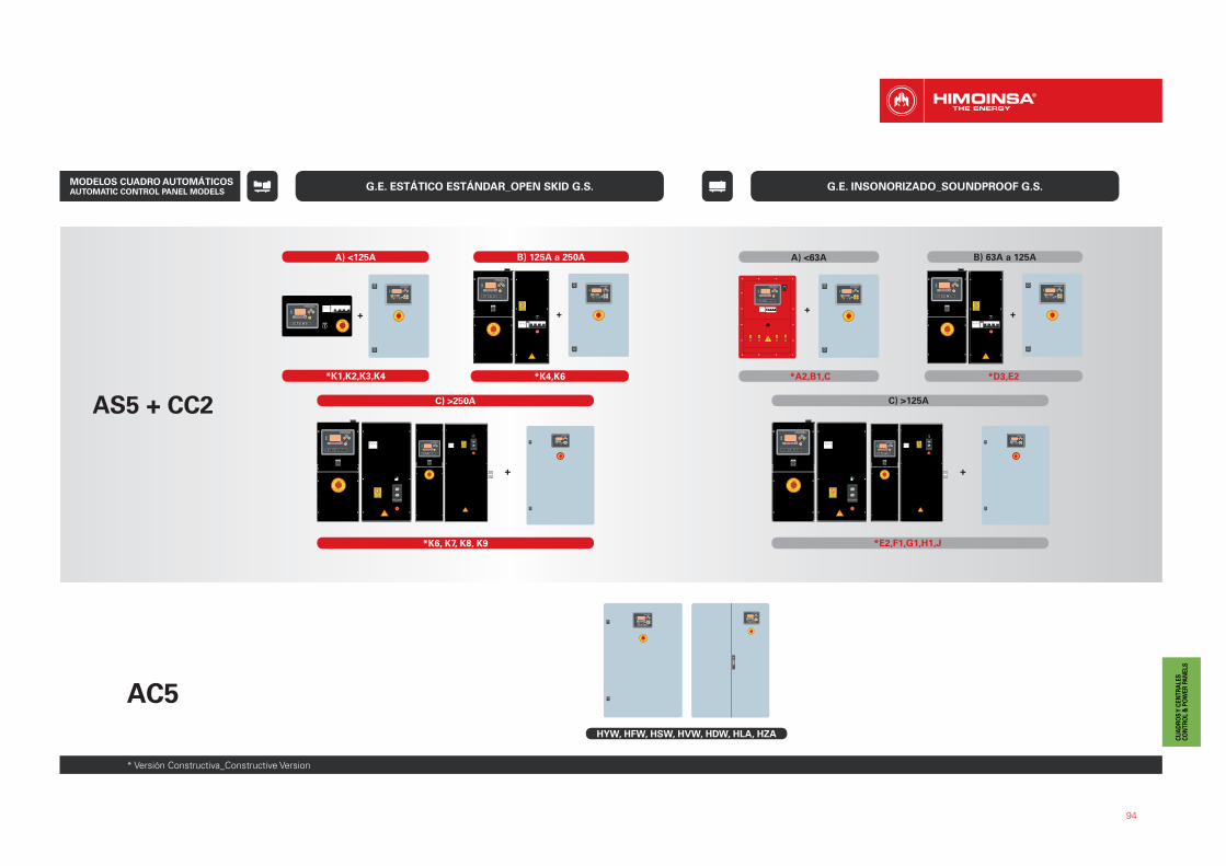
94
G.E. ESTÁTICO ESTÁNDAR_OPEN SKID G.S. G.E. INSONORIZADO_SOUNDPROOF G.S.
* Versión Constructiva_Constructive Version
AS5 + CC2
+
*K6, K7, K8, K9
C) >250A
AC5
HYW, HFW, HSW, HVW, HDW, HLA, HZA
+ +
*K1,K2,K3,K4
B) 125A a 250A
*K4,K6
+
A) <125A
++
A) <63A
*A2,B1,C *D3,E2
B) 63A a 125A
C) >125A
*E2,F1,G1,H1,J
MODELOS CUADRO AUTOMÁTICOS AUTOMATIC CONTROL PANEL MODELS
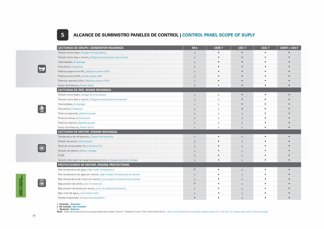
95
LECTURAS DE GRUPO_GENERATOR READINGS M 6 CEM 7 CEC 7 CEA 7 CEM7 + CEC7
Tensión entre fases_Voltage among phases x • • • •
Tensión entre fase y neutro_Voltage among phases and neutral x • • • •
Intensidades_Amperage x • • • •
Frecuencia_Frequency x • • • •
Potencia aparente (kVA)_Apparent power (kVA) x • • • •
Potencia activa (kW)_Active power (kW) x • • • •
Potencia reactiva (kVAr)_Reactive power (kVAr) x • • • •
Factor de Potencia_Power factor x • • • •
LECTURAS DE RED_MAINS READINGS
Tensión entre fases_Voltage among phases x x • • •
Tensión entre fase y neutro_Voltage among phase and neutral x x • • •
Intensidades_Amperage x x • • •
Frecuencia_Frequency x x • • •
Potencia aparente_Aparent power x x x • •
Potencia activa_Active power x x x • •
Potencia reactiva_Reactive power x x x • •
Factor de Potencia_Power factor x x x • •
LECTURAS DE MOTOR_ENGINE READINGS
Temperatura de refrigerante_Coolant temperature x • x • •
Presión de aceite_Oil pressure x • x • •
Nivel de combustible (%)_Fuel level (%) x • x • •
Tensión de batería_Battery voltage x • x • •
R.P.M. x • x • •
Tensión alternador de carga de batería_Battery charge alternator voltage x • x • •
PROTECCIONES DE MOTOR_ENGINE PROTECTIONS
Alta temperatura de agua_High water temperature P • x • •
Alta temperatura de agua por sensor_High coolant temperature by sensor x • x • •
Baja temperatura de motor por sensor_Low engine temperature by sensor x • x • •
Baja presión de aceite_Low oil pressure P • x • •
Baja presión de aceite por sensor_Low oil pressure by sensor x • x • •
Bajo nivel de agua_Low coolant level x • x • •
Parada inesperada_Unexpected shutdown • • x • •
S ALCANCE DE SUMINISTRO PANELES DE CONTROL | CONTROL PANEL SCOPE OF SUPLY
• Estandar _ Standardx No incluido_ Not included• Opcional_ OptionalNota: Todas las protecciones son programables para realizar “Aviso”o “Parada de motor CON o SIN enfriamiento”. _ Note: All the protection are programmable to carry out “warning” or “engine stop with or without cooling”.
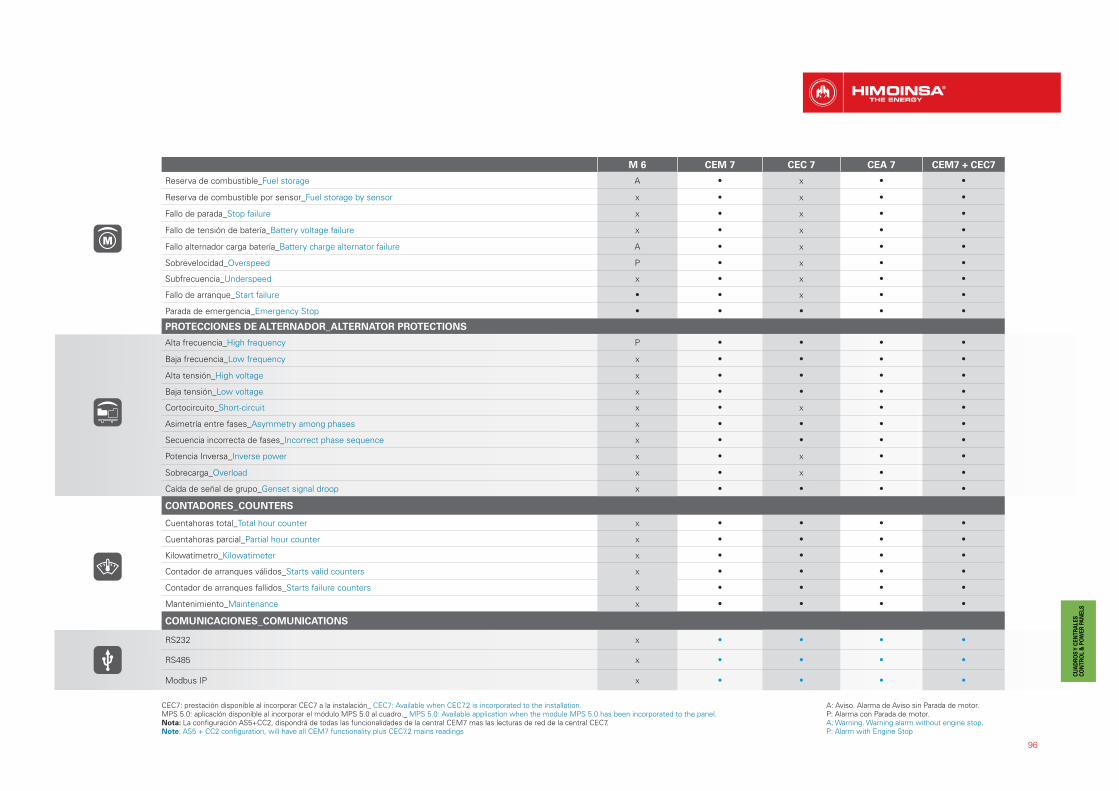
96
M 6 CEM 7 CEC 7 CEA 7 CEM7 + CEC7
Reserva de combustible_Fuel storage A • x • •
Reserva de combustible por sensor_Fuel storage by sensor x • x • •
Fallo de parada_Stop failure x • x • •
Fallo de tensión de batería_Battery voltage failure x • x • •
Fallo alternador carga batería_Battery charge alternator failure A • x • •
Sobrevelocidad_Overspeed P • x • •
Subfrecuencia_Underspeed x • x • •
Fallo de arranque_Start failure • • x • •
Parada de emergencia_Emergency Stop • • • • •
PROTECCIONES DE ALTERNADOR_ALTERNATOR PROTECTIONS
Alta frecuencia_High frequency P • • • •
Baja frecuencia_Low frequency x • • • •
Alta tensión_High voltage x • • • •
Baja tensión_Low voltage x • • • •
Cortocircuito_Short-circuit x • x • •
Asimetría entre fases_Asymmetry among phases x • • • •
Secuencia incorrecta de fases_Incorrect phase sequence x • • • •
Potencia Inversa_Inverse power x • x • •
Sobrecarga_Overload x • x • •
Caída de señal de grupo_Genset signal droop x • • • •
CONTADORES_COUNTERS
Cuentahoras total_Total hour counter x • • • •
Cuentahoras parcial_Partial hour counter x • • • •
Kilowatímetro_Kilowatimeter x • • • •
Contador de arranques válidos_Starts valid counters x • • • •
Contador de arranques fallidos_Starts failure counters x • • • •
Mantenimiento_Maintenance x • • • •
COMUNICACIONES_COMUNICATIONS
RS232 x • • • •
RS485 x • • • •
Modbus IP x • • • •
A: Aviso. Alarma de Aviso sin Parada de motor.P: Alarma con Parada de motor.A: Warning. Warning alarm without engine stop.P: Alarm with Engine Stop
CEC7: prestación disponible al incorporar CEC7 a la instalación_ CEC7: Available when CEC7.2 is incorporated to the installation.MPS 5.0: aplicación disponible al incorporar el módulo MPS 5.0 al cuadro._ MPS 5.0: Available application when the module MPS 5.0 has been incorporated to the panel.Nota: La configuración AS5+CC2, dispondrá de todas las funcionalidades de la central CEM7 mas las lecturas de red de la central CEC7.Note: AS5 + CC2 configuration, will have all CEM7 functionality plus CEC7.2 mains readings

97
COMUNICACIONES_COMUNICATIONS M 6 CEM 7 CEC 7 CEA 7 CEM7 + CEC7
Modbus x • • • •
CCLAN x • x • •
Software para PC_Software for PC x • • • •
Módem analógico_Analogic modem x • • • •
Módem GSM/GPRS_GSM/GPRS modem x • • • •
Pantalla remota_Remote screen x • x • •
Teleseñal_Telesignal x • (8 + 4) x • (8 + 4) • (8 + 4)
J1939 x • x • •
PRESTACIONES_FEATURES
Histórico de alarmas_Alarms history (10) / ( • +100) • • •
Arranque externo_External start • • • • •
Inhibición de arranque_Start inhibition x • • • •
Arranque por fallo de red_Mains failure start x • (CEC 7) • • •
Arranque por normativa EJP_Start under normative EJP x • • (CEM 7) • •
Control de pre-calentamiento de motor_Pre-heating engine control • x • (CEM 7) x x
Activación de contactor de grupo_Genset contactor activation • • • • •
Activación de contactor de Red y Grupo_Main & Genset contactor activation x x • • •
Control del trasiego de combustible_Fuel transfer control x • • (CEM 7) • •
Control de temperatura de motor_Engine temperature control x • • (CEM 7) • •
Marcha forzada de grupo_Manual override x • • (CEM 7) • •
Alarmas libres programables_Programmable alarms x • • (CEM 7) • •
Función de arranque de grupo en modo test_Genset start function in test mode x • • • •
Salidas libres programables_Programmable outputs x • • (CEM 7) • •
Multiligüe_Multilingual x • • • •
APLICACIONES ESPECIALES_SPECIAL FUNCTIONS
Localización GPS_Positioning GPS x • • (CEM 7) • •
Sincronismo_Synchronization with mains x • • (CEM 7) • •
Sincronismo con la red_Mains Synchronism x • • (CEM 7) • •
Eliminación del segundo cero_Second Cero suppression x • • (CEM 7) • •
RAM7 x • • (CEM 7) • •
Panel repetitivo_Remote screen x • • (CEM 7) • •
Reloj programador_Timer x • • (CEM 7) • •
• Estandar _ Standardx No incluido_ Not included• Opcional_ OptionalNota: Todas las protecciones son programables para realizar “Aviso”o “Parada de motor CON o SIN enfriamiento”.Note: All the protection are programmable to carry out “warning” or “engine stop with or without cooling”.
CEC7: prestación disponible al incorporar CEC7 a la instalación_ CEC7: Available when CEC7.2 is incorporated to the installation.MPS 5.0: aplicación disponible al incorporar el módulo MPS 5.0 al cuadro.MPS 5.0: Available application when the module MPS 5.0 has been incorporated to the panel.Nota: La configuración AS5+CC2, dispondrá de todas las funcionalidades de la central CEM7 mas las lecturas de red de la central CEC7.Note: AS5 + CC2 configuration, will have all CEM7 functionality plus CEC7.2 mains readings

MODELOS PANELES DE CONTROL_CONTROL PANEL MODELS
98
(**) Resistencia de caldeo en el grupo y cargador de batería en panel de control incluida. Opción disponible: Cuadro Auto-start sin magnetotérmico.(**) Pre-heating resistance in the Genset and Battery charger in the control panel included.Option available: Auto-start control panel without circuit breaker.
FUNCIONALIDAD_FUNCTIONALITY MODELO CUADRO_PANEL MODEL MODELO CENTRAL_CONTROLLER MODEL
Auto-start (LLAVE)_ Auto-start (KEY START) M6 M6
Auto-start _ Auto-start M5 CEM7
Automático sin control de redAutomatic Control Panel Without Mains Control
AS5 (1) CEM7**
Automático con control de red (conmutación Himoinsa con visualización)_ Automatic Con-trol Panel With Mains Control (Himoinsa change over contactor with display)
AS5 + CC2 CEM7+CEC7
Automático por fallo de red (armario en pared)_ Automatic Mains Failure (wall mounted panel)
AC5 CEA7
1 2 3 4
SIGUIENTE PÁGINA >> NEXT PAGE
(1) Opción AS5 con central CEA7. Cuadro automático SIN conmutación y CON control de red. As optional AS5 with CEA7 Automatic control panel without ATS(automatic transfer switch) and with mains control.
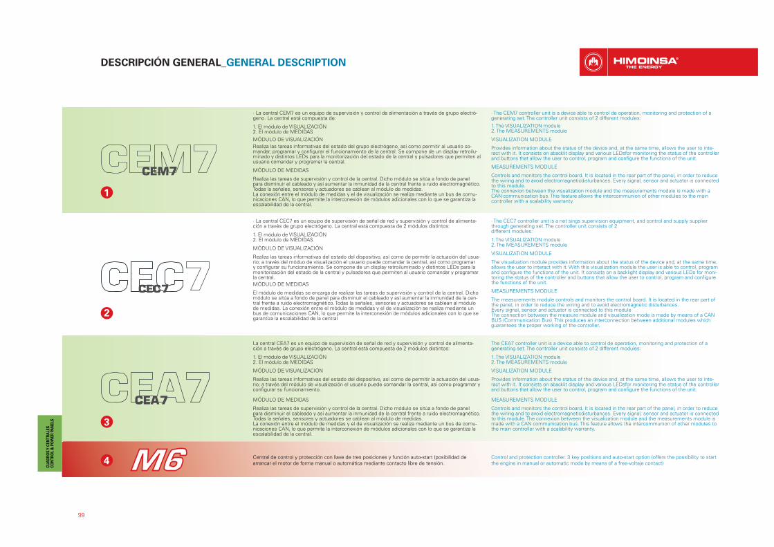
99
DESCRIPCIÓN GENERAL_GENERAL DESCRIPTION
3
4
· La central CEM7 es un equipo de supervisión y control de alimentación a través de grupo electró-geno. La central está compuesta de:
1. El módulo de VISUALIZACIÓN2. El módulo de MEDIDAS
MÓDULO DE VISUALIZACIÓN
Realiza las tareas informativas del estado del grupo electrógeno, así como permitir al usuario co-mandar, programar y configurar el funcionamiento de la central. Se compone de un display retroilu-minado y distintos LEDs para la monitorización del estado de la central y pulsadores que permiten al usuario comandar y programar la central.
MÓDULO DE MEDIDAS
Realiza las tareas de supervisión y control de la central. Dicho módulo se sitúa a fondo de panel para disminuir el cableado y así aumentar la inmunidad de la central frente a ruido electromagnético.Todas la señales, sensores y actuadores se cablean al módulo de medidas.La conexión entre el módulo de medidas y el de visualización se realiza mediante un bus de comu-nicaciones CAN, lo que permite la interconexión de módulos adicionales con lo que se garantiza la escalabilidad de la central.
· The CEM7 controller unit is a device able to control de operation, monitoring and protection of a generating set. The controller unit consists of 2 different modules:
1. The VISUALIZATION module2. The MEASUREMENTS module
VISUALIZATION MODULE
Provides information about the status of the device and, at the same time, allows the user to inte-ract with it. It consists on abacklit display and various LEDsfor monitoring the status of the controller and buttons that allow the user to control, program and configure the functions of the unit.
MEASUREMENTS MODULE
Controls and monitors the control board. It is located in the rear part of the panel, in order to reduce the wiring and to avoid electromagneticdisturbances. Every signal, sensor and actuator is connected to this module.The connexion between the visualization module and the measurements module is made with a CAN communication bus. This feature allows the intercommunion of other modules to the main controller with a scalability warranty.
1
2
· La central CEC7 es un equipo de supervisión de señal de red y supervisión y control de alimenta-ción a través de grupo electrógeno. La central está compuesta de 2 módulos distintos:
1. El módulo de VISUALIZACIÓN2. El módulo de MEDIDAS
MÓDULO DE VISUALIZACIÓN
Realiza las tareas informativas del estado del dispositivo, así como de permitir la actuación del usua-rio; a través del móduo de visualización el usuario puede comandar la central, así como programar y configurar su funcionamiento. Se compone de un display retroiluminado y distintos LEDs para la monitorización del estado de la central y pulsadores que permiten al usuario comandar y programar la central.
MÓDULO DE MEDIDAS
El módulo de medidas se encarga de realizar las tareas de supervisión y control de la central. Dicho módulo se sitúa a fondo de panel para disminuir el cableado y así aumentar la inmunidad de la cen-tral frente a ruido electromagnético. Todas la señales, sensores y actuadores se cablean al módulode medidas. La conexión entre el módulo de medidas y el de visualización se realiza mediante un bus de comunicaciones CAN, lo que permite la interconexión de módulos adicionales con lo que se garantiza la escalabilidad de la central
· The CEC7 controller unit is a net sings supervision equipment, and control and supply supplier through generating set. The controller unit consists of 2different modules:
1. The VISUALIZATION module2. The MEASUREMENTS module
VISUALIZATION MODULE
The visualization module provides information about the status of the device and, at the same time, allows the user to interact with it. With this visualization module the user is able to control, program and configure the functions of the unit. It consists on a backlight display and various LEDs for moni-toring the status of the controller and buttons that allow the user to control, program and configure the functions of the unit.
MEASUREMENTS MODULE
The measurements module controls and monitors the control board. It is located in the rear part of the panel, in order to reduce the wiring and to avoid electromagnetic disturbances.Every signal, sensor and actuator is connected to this moduleThe connection between the measure module and visualization mode is made by means of a CAN BUS (Communication Bus). This produces an interconnection between additional modules which guarantees the proper working of the controller.
La central CEA7 es un equipo de supervisión de señal de red y supervisión y control de alimenta-ción a través de grupo electrógeno. La central está compuesta de 2 módulos distintos:
1. El módulo de VISUALIZACIÓN2. El módulo de MEDIDAS
MÓDULO DE VISUALIZACIÓN
Realiza las tareas informativas del estado del dispositivo, así como de permitir la actuación del usua-rio; a través del módulo de visualización el usuario puede comandar la central, así como programar y configurar su funcionamiento.
MÓDULO DE MEDIDAS
Realiza las tareas de supervisión y control de la central. Dicho módulo se sitúa a fondo de panel para disminuir el cableado y así aumentar la inmunidad de la central frente a ruido electromagnético. Todas la señales, sensores y actuadores se cablean al módulo de medidas.La conexión entre el módulo de medidas y el de visualización se realiza mediante un bus de comu-nicaciones CAN, lo que permite la interconexión de módulos adicionales con lo que se garantiza la escalabilidad de la central.
The CEA7 controller unit is a device able to control de operation, monitoring and protection of a generating set. The controller unit consists of 2 different modules:
1. The VISUALIZATION module2. The MEASUREMENTS module
VISUALIZATION MODULE
Provides information about the status of the device and, at the same time, allows the user to inte-ract with it. It consists on abacklit display and various LEDsfor monitoring the status of the controller and buttons that allow the user to control, program and configure the functions of the unit.
MEASUREMENTS MODULE
Controls and monitors the control board. It is located in the rear part of the panel, in order to reduce the wiring and to avoid electromagneticdisturbances. Every signal, sensor and actuator is connected to this module. The connexion between the visualization module and the measurements module is made with a CAN communication bus. This feature allows the intercommunion of other modules to the main controller with a scalability warranty.
Central de control y protección con llave de tres posiciones y función auto-start (posibilidad de arrancar el motor de forma manual o automática mediante contacto libre de tensión.
Control and protection controller. 3 key positions and auto-start option (offers the possibility to start the engine in manual or automatic mode by means of a free-voltaje contact)

100
OP
OPCIONALES_OPTIONALS: GAMA PROFESIONAL_PROFESSIONAL RANGE
GAMA HR_HR RANGE
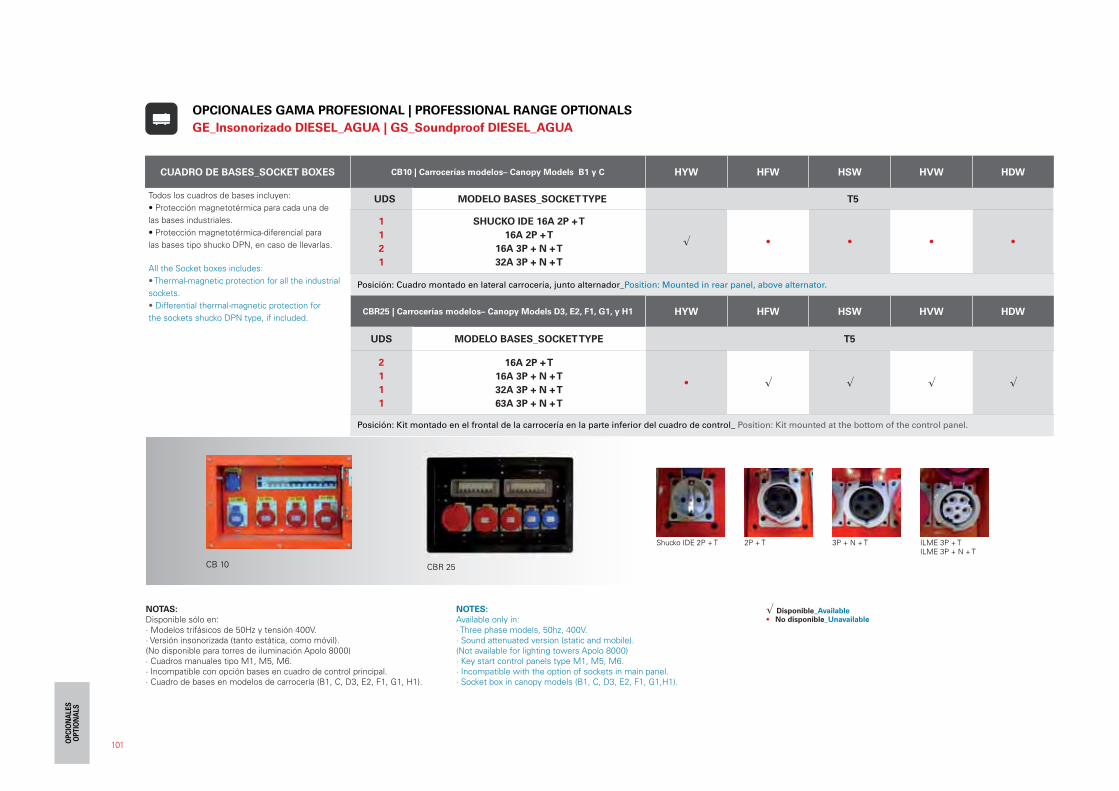
101
CUADRO DE BASES_SOCKET BOXES CB10 | Carrocerías modelos– Canopy Models B1 y C HYW HFW HSW HVW HDW
Todos los cuadros de bases incluyen:
• Protección magnetotérmica para cada una de
las bases industriales.
• Protección magnetotérmica-diferencial para
las bases tipo shucko DPN, en caso de llevarlas.
All the Socket boxes includes:
• Thermal-magnetic protection for all the industrial
sockets.
• Differential thermal-magnetic protection for
the sockets shucko DPN type, if included.
UDS MODELO BASES_SOCKET TYPE T5
1
1
2
1
SHUCKO IDE 16A 2P + T
16A 2P + T
16A 3P + N + T
32A 3P + N + T
� • • • •
Posición: Cuadro montado en lateral carrocería, junto alternador_Position: Mounted in rear panel, above alternator.
CBR25 | Carrocerías modelos– Canopy Models D3, E2, F1, G1, y H1 HYW HFW HSW HVW HDW
UDS MODELO BASES_SOCKET TYPE T5
2
1
1
1
16A 2P + T
16A 3P + N + T
32A 3P + N + T
63A 3P + N + T
• � � � �
Posición: Kit montado en el frontal de la carrocería en la parte inferior del cuadro de control_ Position: Kit mounted at the bottom of the control panel.
Shucko IDE 2P + T 2P + T 3P + N + T ILME 3P + TILME 3P + N + T
CB 10
OPCIONALES GAMA PROFESIONAL | PROFESSIONAL RANGE OPTIONALS
GE_Insonorizado DIESEL_AGUA | GS_Soundproof DIESEL_AGUA
CBR 25
NOTAS:
Disponible sólo en:· Modelos trifásicos de 50Hz y tensión 400V.· Versión insonorizada (tanto estática, como móvil). (No disponible para torres de iluminación Apolo 8000)· Cuadros manuales tipo M1, M5, M6.· Incompatible con opción bases en cuadro de control principal.· Cuadro de bases en modelos de carrocería (B1, C, D3, E2, F1, G1, H1).
NOTES:
Available only in:· Three phase models, 50hz, 400V.· Sound attenuated version (static and mobile). (Not available for lighting towers Apolo 8000)· Key start control panels type M1, M5, M6.· Incompatible with the option of sockets in main panel.· Socket box in canopy models (B1, C, D3, E2, F1, G1,H1).
� Disponible_Available• No disponible_Unavailable
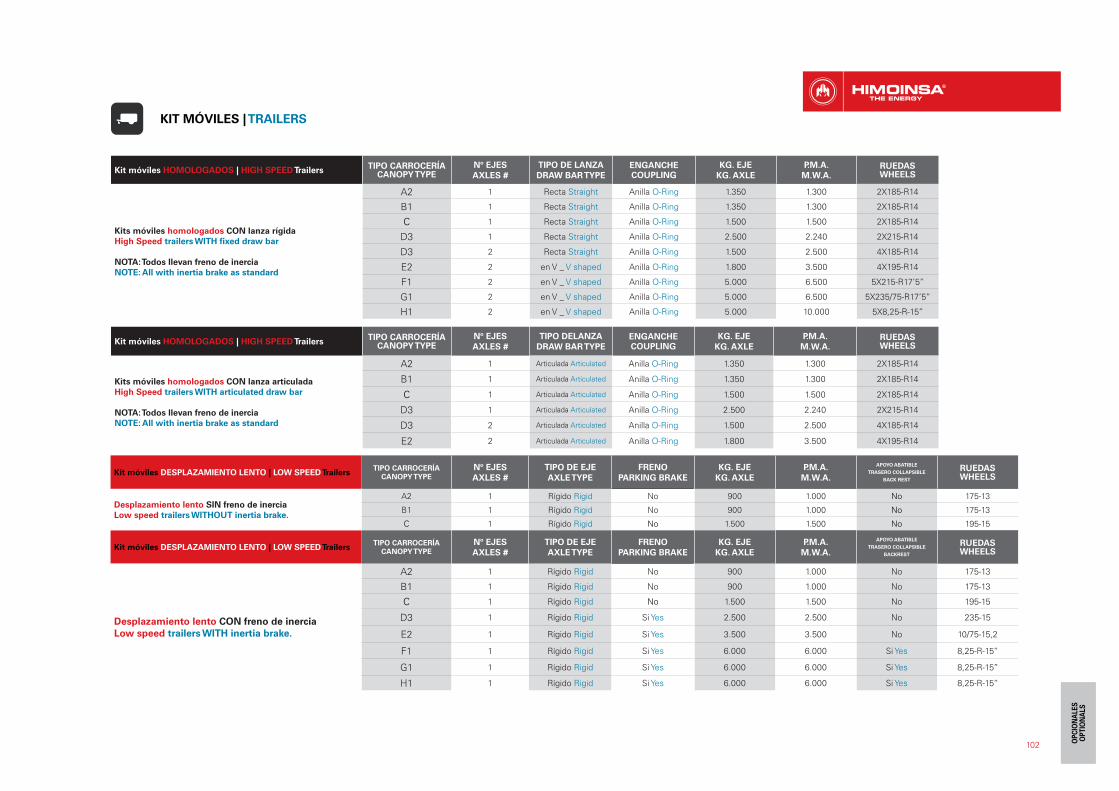
102
Kit móviles DESPLAZAMIENTO LENTO | LOW SPEED TrailersTIPO CARROCERÍA
CANOPY TYPE
Nº EJES
AXLES #
TIPO DE EJE
AXLE TYPE
FRENO
PARKING BRAKE
KG. EJE
KG. AXLE
P.M.A.
M.W.A.
APOYO ABATIBLE
TRASERO COLLAPSIBLE
BACK REST
RUEDASWHEELS
Desplazamiento lento SIN freno de inercia
Low speed trailers WITHOUT inertia brake.
A2 1 Rígido Rigid No 900 1.000 No 175-13
B1 1 Rígido Rigid No 900 1.000 No 175-13
C 1 Rígido Rigid No 1.500 1.500 No 195-15
Kit móviles DESPLAZAMIENTO LENTO | LOW SPEED TrailersTIPO CARROCERÍA
CANOPY TYPE
Nº EJES
AXLES #
TIPO DE EJE
AXLE TYPE
FRENO
PARKING BRAKE
KG. EJE
KG. AXLE
P.M.A.
M.W.A.
APOYO ABATIBLE
TRASERO COLLAPSIBLE
BACKREST
RUEDASWHEELS
Desplazamiento lento CON freno de inercia
Low speed trailers WITH inertia brake.
A2 1 Rígido Rigid No 900 1.000 No 175-13
B1 1 Rígido Rigid No 900 1.000 No 175-13
C 1 Rígido Rigid No 1.500 1.500 No 195-15
D3 1 Rígido Rigid Si Yes 2.500 2.500 No 235-15
E2 1 Rígido Rigid Si Yes 3.500 3.500 No 10/75-15,2
F1 1 Rígido Rigid Si Yes 6.000 6.000 Si Yes 8,25-R-15’’
G1 1 Rígido Rigid Si Yes 6.000 6.000 Si Yes 8,25-R-15’’
H1 1 Rígido Rigid Si Yes 6.000 6.000 Si Yes 8,25-R-15’’
Kit móviles HOMOLOGADOS | HIGH SPEED TrailersTIPO CARROCERÍA
CANOPY TYPENº EJES
AXLES #
TIPO DE LANZA
DRAW BAR TYPEENGANCHECOUPLING
KG. EJE
KG. AXLE
P.M.A.
M.W.A.RUEDASWHEELS
Kits móviles homologados CON lanza rígida
High Speed trailers WITH fixed draw bar
NOTA: Todos llevan freno de inercia
NOTE: All with inertia brake as standard
A2 1 Recta Straight Anilla O-Ring 1.350 1.300 2X185-R14
B1 1 Recta Straight Anilla O-Ring 1.350 1.300 2X185-R14
C 1 Recta Straight Anilla O-Ring 1.500 1.500 2X185-R14
D3 1 Recta Straight Anilla O-Ring 2.500 2.240 2X215-R14
D3 2 Recta Straight Anilla O-Ring 1.500 2.500 4X185-R14
E2 2 en V _ V shaped Anilla O-Ring 1.800 3.500 4X195-R14
F1 2 en V _ V shaped Anilla O-Ring 5.000 6.500 5X215-R17’5’’
G1 2 en V _ V shaped Anilla O-Ring 5.000 6.500 5X235/75-R17’5’’
H1 2 en V _ V shaped Anilla O-Ring 5.000 10.000 5X8,25-R-15’’
Kit móviles HOMOLOGADOS | HIGH SPEED TrailersTIPO CARROCERÍA
CANOPY TYPENº EJES
AXLES #
TIPO DELANZA
DRAW BAR TYPEENGANCHECOUPLING
KG. EJE
KG. AXLE
P.M.A.
M.W.A.RUEDASWHEELS
Kits móviles homologados CON lanza articulada
High Speed trailers WITH articulated draw bar
NOTA: Todos llevan freno de inercia
NOTE: All with inertia brake as standard
A2 1 Articulada Articulated Anilla O-Ring 1.350 1.300 2X185-R14
B1 1 Articulada Articulated Anilla O-Ring 1.350 1.300 2X185-R14
C 1 Articulada Articulated Anilla O-Ring 1.500 1.500 2X185-R14
D3 1 Articulada Articulated Anilla O-Ring 2.500 2.240 2X215-R14
D3 2 Articulada Articulated Anilla O-Ring 1.500 2.500 4X185-R14
E2 2 Articulada Articulated Anilla O-Ring 1.800 3.500 4X195-R14
KIT MÓVILES | TRAILERS
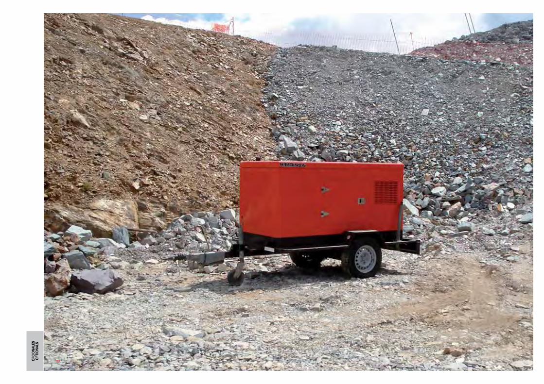
103

104
DEPÓSITO DE GRAN CAPACIDAD | HIGH CAPACITY FUEL TANKTIPO CARROCERÍA
CANOPY TYPE
Dimensiones con tanque de G.C.largo x ancho x alto
Dimensions with H.C. tanklength x width x height
CAPACIDAD L CAPACITY L
• Depósito metálico que permite aumentar la capacidad estándar del
depósito de combustible de la versión insonorizada_Metal fuel tank which
increases the capacity of the standard fuel tank for the soundproof models.
Estos depósitos están fabricados en chapa de alta resistencia, con refuerzos
interiores que evitan el traslado rápido del combustible y su derrame,
sobretodo en el caso del izado del grupo electrógeno.Incorporan boca de
llenado metálica de 120mm de diámetro. Están preparados para garantizar el
suministro del grupo al 100 % de la carga entre 20-24 horas. (según modelos
y consumos)
These fuel tanks are made of high resistance steel plates, with interior rein-
forcements to avoid the fast movement of the fuel and its spillage, mainly in
the event of lifting of the generating set.
Fuel filling opening of 120mm of diameter.Prepared to guarantee the fuel su-
pply of the genset at 100% load during 20-24 hours. (depending on models
consumptions).
B1 2000 x 950 x 1410 200
C 2250 x 1050 x 1650 312
D3 2750 x 1100 x 1850 540
E2 3300 x 1200 x 2150 750
F1 3800 x 1400 x 2435 995
G1 4100 x 1600 x 2610 1.660
H1 4500 x 1800 x 2800 2.100
PATÍN DE ARRASTRE | PULLING SKIDTIPO CARROCERÍA
CANOPY TYPE
Dimensiones con tanque de G.C.largo x ancho x alto
Dimensions with H.C. tanklength x width x height
• Patín de alta resistencia, que permite reforzar el chasis y proteger la carro-cería_High resistance skid, that allows to reinforce the chassis and to protect the canopy.
Estos patines dan mayor rigidez a la carrocería al garantizar un momento
flector muy por encima del ofrecido por los patines de suministro estándar.
Igualmente, alejan el grupo electrógeno de posibles golpes de pequeña
maquinaria, protegiendo el chasis y la carrocería.
El patín de arrastre como indica su nombre, es óptimo para el arrastre de la
máquina y su trabajo en superficies irregulares.
These skids offer more stiffness to the canopy since they guarantee a
“bending moment” much higher than the one offered by the standard skids.
Moreover, it protects the chassis and canopy of the genset from hits caused
by small machinery. As its name indicates, the pulling skid is best solution
for the pulling of the machine on irregular surfaces.
A2 2.020 x 1.010 x 1.270
B1 2.100 x 1.060 x 1.310
C 2.350 x 1.160 x 1.490
D3 2.850 x 1.230 x 1.540
E2 3.540 x 1.340 x 1.850
F1 3.890 x 1.540 x 2.305
G1 4.340 x 1.780 x 2.410
H1 4.740 x 1.980 x 2.600
+ L = 24 H
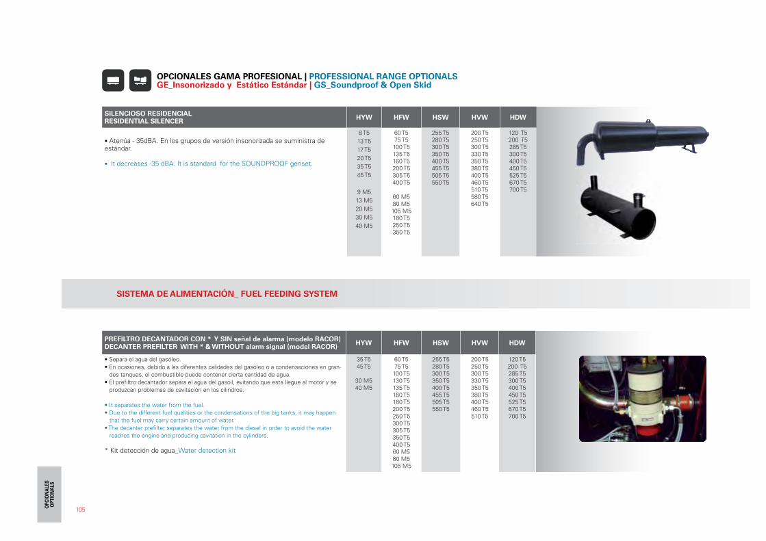
105
SILENCIOSO RESIDENCIALRESIDENTIAL SILENCER
HYW HFW HSW HVW HDW
• Atenúa - 35dBA. En los grupos de versión insonorizada se suministra deestándar.
• It decreases -35 dBA. It is standard for the SOUNDPROOF genset.
8 T5
13 T5
17 T5
20 T5
35 T5
45 T5
9 M5
13 M5
20 M5
30 M5
40 M5
60 T5 75 T5 100 T5 135 T5160 T5 200 T5 305 T5 400 T5
60 M580 M5105 M5180 T5 250 T5350 T5
255 T5280 T5300 T5350 T5400 T5455 T5505 T5550 T5
200 T5250 T5300 T5330 T5350 T5380 T5400 T5460 T5510 T5580 T5640 T5
120 T5200 T5285 T5300 T5400 T5450 T5525 T5670 T5700 T5
OPCIONALES GAMA PROFESIONAL | PROFESSIONAL RANGE OPTIONALS GE_Insonorizado y Estático Estándar | GS_Soundproof & Open Skid
SISTEMA DE ALIMENTACIÓN_ FUEL FEEDING SYSTEM
PREFILTRO DECANTADOR CON * Y SIN señal de alarma (modelo RACOR)DECANTER PREFILTER WITH * & WITHOUT alarm signal (model RACOR)
HYW HFW HSW HVW HDW
• Separa el agua del gasóleo.
• En ocasiones, debido a las diferentes calidades del gasóleo o a condensaciones en gran-
des tanques, el combustible puede contener cierta cantidad de agua.
• El prefiltro decantador separa el agua del gasoil, evitando que esta llegue al motor y se
produzcan problemas de cavitación en los cilindros.
• It separates the water from the fuel.
• Due to the different fuel qualities or the condensations of the big tanks, it may happen
that the fuel may carry certain amount of water.
• The decanter prefilter separates the water from the diesel in order to avoid the water
reaches the engine and producing cavitation in the cylinders.
* Kit detección de agua_Water detection kit
35 T545 T5
30 M540 M5
60 T5 75 T5 100 T5 130 T5135 T5 160 T5180 T5200 T5250 T5300 T5305 T5350 T5400 T560 M580 M5105 M5
255 T5280 T5300 T5350 T5400 T5455 T5505 T5550 T5
200 T5250 T5300 T5330 T5350 T5380 T5400 T5460 T5510 T5
120 T5200 T5285 T5300 T5400 T5450 T5525 T5670 T5700 T5
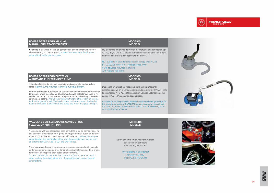
VÁLVULA 3 VÍAS LLENADO DE COMBUSTIBLE
3 WAY VALVE FUEL FILLING
MODELOS
MODELS
• Sistema de válvulas preparadas para permitir la toma de combustible, ya
sea desde el propio tanque del grupo electrogeno o bien desde un tanque
externo. Disponible en conexiones de 1/2” y de 3/8”_ Valves system pre-
pared to allow the fuel intake, either from the genset’s own tank or from
an external tank. Available in 1/2” and 3/8” fittings.
Sistema preparado para la conexión de mangueras de combustible desde
un tanque externo, para permitir tomar el combustible bien desde el propio
tanque del electrogeno, bien desde tanque externo.
System prepared for the hose fuel connection from an external tank in
order to allow the intake either from the genset´s own tank or from an
external tank.
Sólo disponible en grupos insonorizados
con versión de carrocería
tipo: D3, E2, F1, G1, H1
Only available in Soundproof
gensets in canopy
type: D3, E2, F1, G1, H1
106
BOMBA DE TRASIEGO MANUAL
MANUAL FUEL TRANSFER PUMP
MODELOS
MODELS
• Permite el traspaso manual de combustible desde un tanque externo
al tanque del grupo electrógeno_ It allows the transfer of fuel from an
external tank to the genset´s tank.
NO disponble en grupos de versión insonorizada con carrocerías tipo
A1, A2, B1, C, D3, E2. Nota: se suministrará suelta, sólo se entrega-
rá montada en chasis con depósitos metálicos.
NOT available in Soundproof genset in canopy type:A1, A2,
B1, C, D3, E2. Note: It will supplied loose. Only
it will delivered mounted in chassis
with metallic fuel tanks.
BOMBA DE TRASIEGO ELÉCTRICA
AUTOMATIC FUEL TRANSFER PUMP
MODELOS
MODELS
• Bomba eléctrica de trasiego montada en chasis, sistema de nivel de
carga_Electric pump mounted in chassis, fuel level system.
Permite el traspaso automático de combustible desde un tanque externo al tanque del grupo electrógeno. El sistema de nivel, detectará cuando el ni-vel del tanque de combustible es bajo para arrancar la bomba y cuando es optimo para pararla_ Allows the automatic transfer of fuel from an external tank to the genset’s tank. The level system, will detect when the level of fuel from the tank is low to start the pump and when it is good to stop it.
Disponible en grupos electrógenos de la gama profesional
diesel agua salvo en la versión insonorizada con motor YANMAR para
tipo carrocería A1 y A2. Nota: en versión Estático Estándar para las
gamas HYW, HZA, consultar disponibilidad.
Available for all the professional diesel water cooled range except for the soundproof units with YANMAR engine in canopy type A1 and A2 . Note: in the Open Skid version please ask for availability in the new constructive versions.
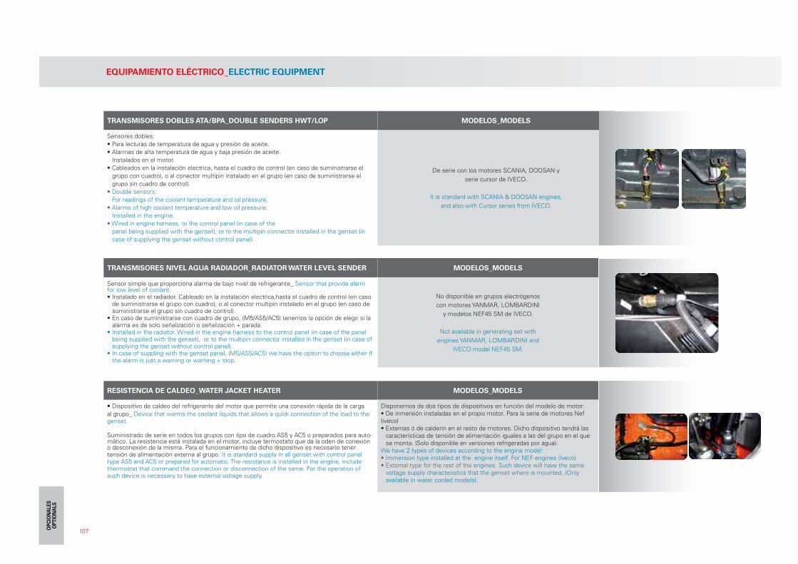
107
TRANSMISORES DOBLES ATA/BPA_DOUBLE SENDERS HWT/LOP MODELOS_MODELS
Sensores dobles:
• Para lecturas de temperatura de agua y presión de aceite.
• Alarmas de alta temperatura de agua y baja presión de aceite.
Instalados en el motor.
• Cableados en la instalación electrica, hasta el cuadro de control (en caso de suministrarse el
grupo con cuadro), o al conector multipin instalado en el grupo (en caso de suministrarse el
grupo sin cuadro de control).
• Double sensors:
For readings of the coolant temperature and oil pressure.
• Alarms of high coolant temperature and low oil pressure:
Installed in the engine.
• Wired in engine harness, to the control panel (in case of the
panel being supplied with the genset), or to the multipin connector installed in the genset (in
case of supplying the genset without control panel).
De serie con los motores SCANIA, DOOSAN y
serie cursor de IVECO.
It is standard with SCANIA & DOOSAN engines,
and also with Cursor series from IVECO.
TRANSMISORES NIVEL AGUA RADIADOR_RADIATOR WATER LEVEL SENDER MODELOS_MODELS
Sensor simple que proporciona alarma de bajo nivel de refrigerante_ Sensor that provide alarm for low level of coolant.• Instalado en el radiador. Cableado en la instalación electrica,hasta el cuadro de control (en caso
de suministrarse el grupo con cuadro), o al conector multipin instalado en el grupo (en caso de suministrarse el grupo sin cuadro de control).
• En caso de suministrarse con cuadro de grupo, (M5/AS5/AC5) tenemos la opción de elegir si la alarma es de solo señalización o señalización + parada.
• Installed in the radiator. Wired in the engine harness to the control panel (in case of the panel being supplied with the genset), or to the multipin connector installed in the genset (in case of supplying the genset without control panel).
• In case of suppling with the genset panel, (M5/AS5/AC5) we have the option to choose either if the alarm is just a warning or warning + stop.
No disponible en grupos electrógenos
con motores YANMAR, LOMBARDINI
y modelos NEF45 SM de IVECO.
Not available in generating set with
engines YANMAR, LOMBARDINI and
IVECO model NEF45 SM.
RESISTENCIA DE CALDEO_WATER JACKET HEATER MODELOS_MODELS
• Dispositivo de caldeo del refrigerante del motor que permite una conexión rápida de la carga
al grupo_ Device that warms the coolant liquids that allows a quick connection of the load to the genset.
Suministrado de serie en todos los grupos con tipo de cuadro AS5 y AC5 o preparados para auto-mático. La resistencia está instalada en el motor, incluye termostato que da la oden de conexión o desconexión de la misma. Para el funcionamiento de dicho dispositivo es necesario tener tensión de alimentación externa al grupo. It is standard supply in all genset with control panel type AS5 and AC5 or prepared for automatic. The resistance is installed in the engine, include thermostat that command the connection or disconnection of the same. For the operation of such device is necessary to have external voltage supply.
Disponemos de dos tipos de dispositivos en función del modelo de motor:• De inmersión instaladas en el propio motor. Para la serie de motores Nef (iveco)• Externas ó de calderin en el resto de motores. Dicho dispositivo tendrá las
características de tensión de alimentación iguales a las del grupo en el que se monta. (Solo disponible en versiones refrigeradas por agua).
We have 2 types of devices according to the engine model:• Immersion type installed at the engine itself. For NEF engines (Iveco)• External type for the rest of the engines. Such device will have the same
voltage supply characteristics that the genset where is mounted. (Only available in water cooled models).
EQUIPAMIENTO ELÉCTRICO_ELECTRIC EQUIPMENT
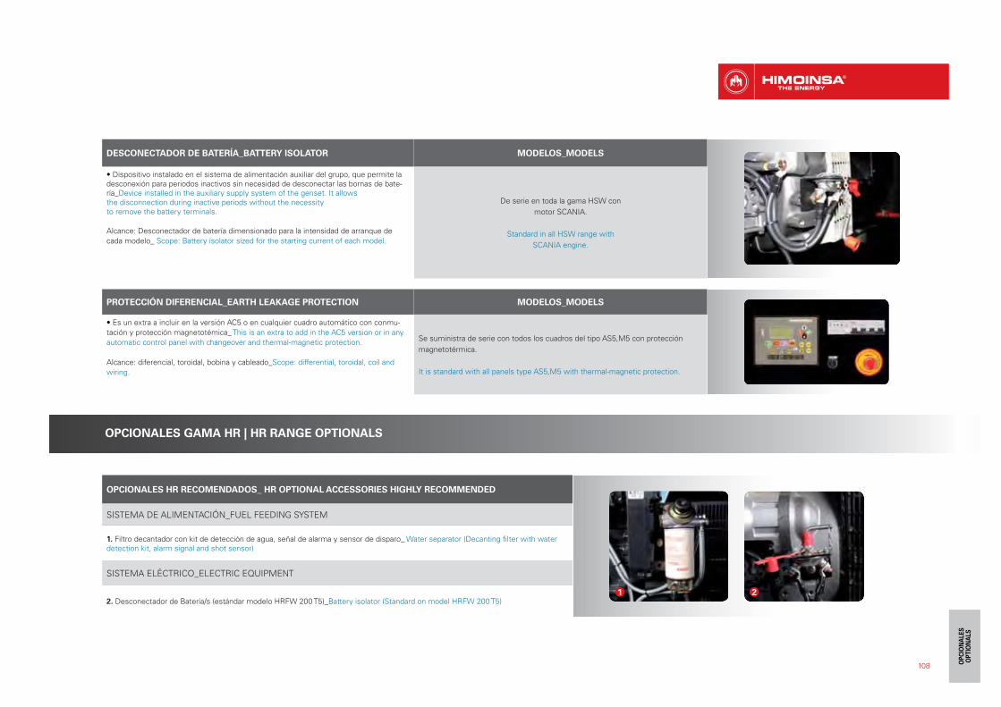
108
DESCONECTADOR DE BATERÍA_BATTERY ISOLATOR MODELOS_MODELS
• Dispositivo instalado en el sistema de alimentación auxiliar del grupo, que permite la desconexión para periodos inactivos sin necesidad de desconectar las bornas de bate-ría_Device installed in the auxiliary supply system of the genset. It allowsthe disconnection during inactive periods without the necessityto remove the battery terminals.
Alcance: Desconectador de batería dimensionado para la intensidad de arranque de
cada modelo_ Scope: Battery isolator sized for the starting current of each model.
De serie en toda la gama HSW con
motor SCANIA.
Standard in all HSW range with
SCANIA engine.
PROTECCIÓN DIFERENCIAL_EARTH LEAKAGE PROTECTION MODELOS_MODELS
• Es un extra a incluir en la versión AC5 o en cualquier cuadro automático con conmu-
tación y protección magnetotémica_ This is an extra to add in the AC5 version or in any
automatic control panel with changeover and thermal-magnetic protection.
Alcance: diferencial, toroidal, bobina y cableado_Scope: differential, toroidal, coil and
wiring.
Se suministra de serie con todos los cuadros del tipo AS5,M5 con protección
magnetotérmica.
It is standard with all panels type AS5,M5 with thermal-magnetic protection.
OPCIONALES GAMA HR | HR RANGE OPTIONALS
OPCIONALES HR RECOMENDADOS_ HR OPTIONAL ACCESSORIES HIGHLY RECOMMENDED
SISTEMA DE ALIMENTACIÓN_FUEL FEEDING SYSTEM
1. Filtro decantador con kit de detección de agua, señal de alarma y sensor de disparo_ Water separator (Decanting filter with water detection kit, alarm signal and shot sensor)
SISTEMA ELÉCTRICO_ELECTRIC EQUIPMENT
2. Desconectador de Batería/s (estándar modelo HRFW 200 T5)_Battery isolator (Standard on model HRFW 200 T5)1 2
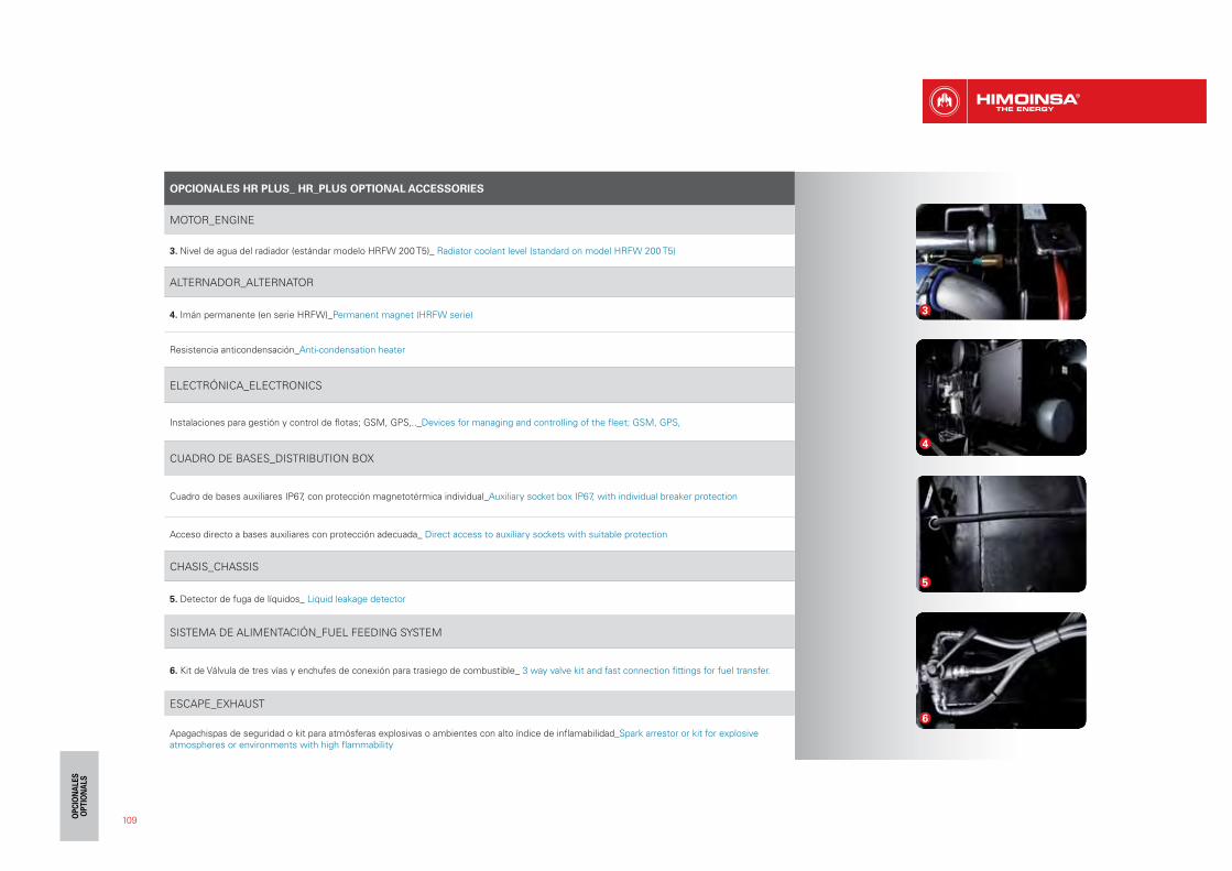
OPCIONALES HR PLUS_ HR_PLUS OPTIONAL ACCESSORIES
MOTOR_ENGINE
3. Nivel de agua del radiador (estándar modelo HRFW 200 T5)_ Radiator coolant level (standard on model HRFW 200 T5)
ALTERNADOR_ALTERNATOR
4. Imán permanente (en serie HRFW)_Permanent magnet (HRFW serie)
Resistencia anticondensación_Anti-condensation heater
ELECTRÓNICA_ELECTRONICS
Instalaciones para gestión y control de flotas; GSM, GPS,.._Devices for managing and controlling of the fleet; GSM, GPS,
CUADRO DE BASES_DISTRIBUTION BOX
Cuadro de bases auxiliares IP67, con protección magnetotérmica individual_Auxiliary socket box IP67, with individual breaker protection
Acceso directo a bases auxiliares con protección adecuada_ Direct access to auxiliary sockets with suitable protection
CHASIS_CHASSIS
5. Detector de fuga de líquidos_ Liquid leakage detector
SISTEMA DE ALIMENTACIÓN_FUEL FEEDING SYSTEM
6. Kit de Válvula de tres vías y enchufes de conexión para trasiego de combustible_ 3 way valve kit and fast connection fittings for fuel transfer.
ESCAPE_EXHAUST
Apagachispas de seguridad o kit para atmósferas explosivas o ambientes con alto índice de inflamabilidad_Spark arrestor or kit for explosive atmospheres or environments with high flammability
3
4
5
6
109