Embed Size (px)
Citation preview
Hipulse System GuideUPS FOR THE DIGITAL WORLD
Power Quality Book4a
Version 1.0

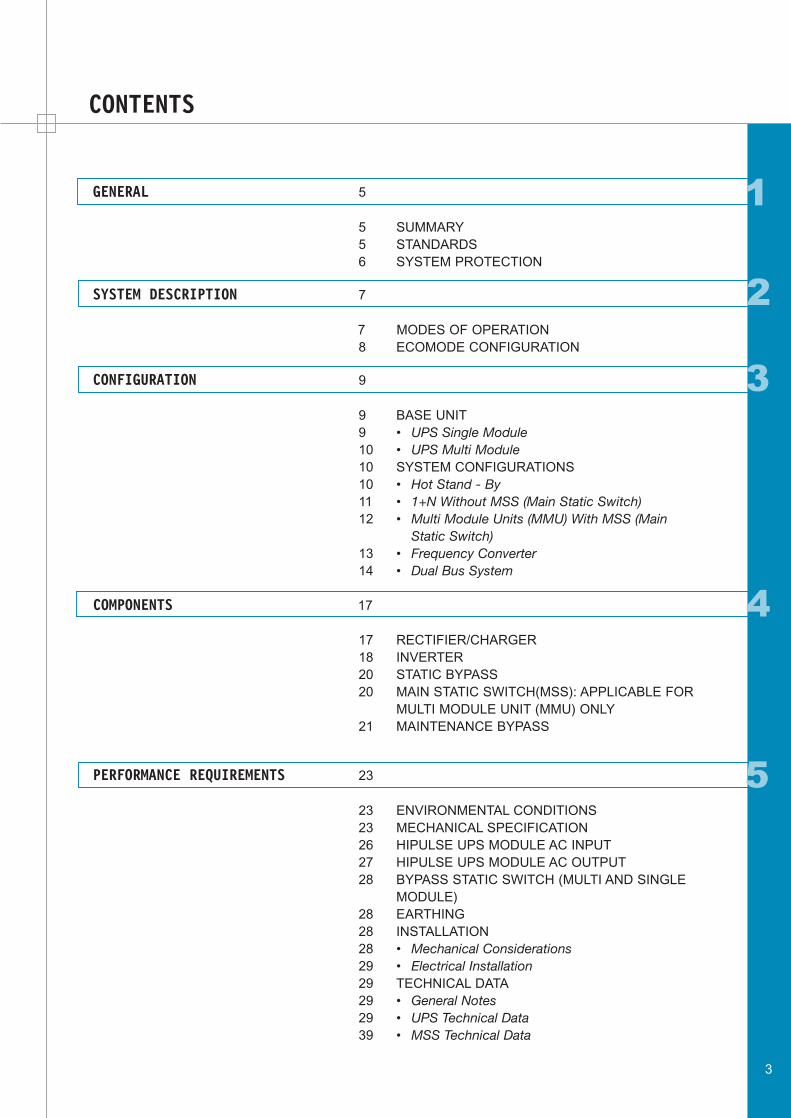
CONTENTS
1GENERAL 5
5 SUMMARY5 STANDARDS6 SYSTEM PROTECTION
SYSTEM DESCRIPTION 7
7 MODES OF OPERATION8 ECOMODE CONFIGURATION
CONFIGURATION 9
9 BASE UNIT9 • UPS Single Module10 • UPS Multi Module10 SYSTEM CONFIGURATIONS10 • Hot Stand - By11 • 1+N Without MSS (Main Static Switch)12 • Multi Module Units (MMU) With MSS (Main
Static Switch)13 • Frequency Converter14 • Dual Bus System
COMPONENTS 17
17 RECTIFIER/CHARGER18 INVERTER20 STATIC BYPASS20 MAIN STATIC SWITCH(MSS): APPLICABLE FOR
MULTI MODULE UNIT (MMU) ONLY21 MAINTENANCE BYPASS
PERFORMANCE REQUIREMENTS 23
23 ENVIRONMENTAL CONDITIONS23 MECHANICAL SPECIFICATION26 HIPULSE UPS MODULE AC INPUT27 HIPULSE UPS MODULE AC OUTPUT28 BYPASS STATIC SWITCH (MULTI AND SINGLE
MODULE)28 EARTHING28 INSTALLATION28 • Mechanical Considerations29 • Electrical Installation29 TECHNICAL DATA29 • General Notes29 • UPS Technical Data39 • MSS Technical Data
3
4
2
3
5
6
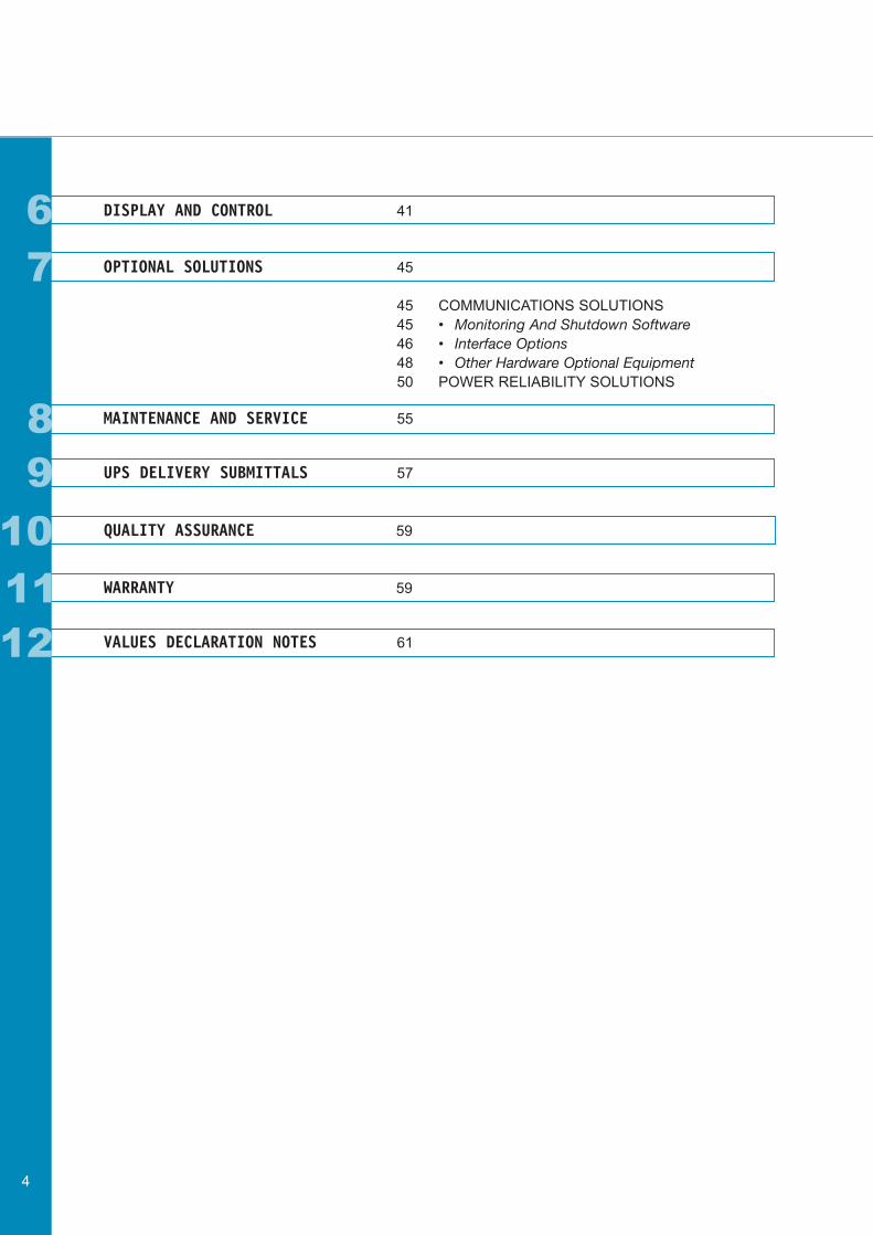
6 DISPLAY AND CONTROL 41
OPTIONAL SOLUTIONS 45
45 COMMUNICATIONS SOLUTIONS45 • Monitoring And Shutdown Software46 • Interface Options48 • Other Hardware Optional Equipment50 POWER RELIABILITY SOLUTIONS
MAINTENANCE AND SERVICE 55
UPS DELIVERY SUBMITTALS 57
QUALITY ASSURANCE 59
WARRANTY 59
VALUES DECLARATION NOTES 61
4
7
89
11
10
12
1
5
GENERAL
SUMMARY
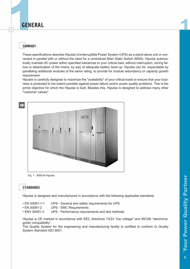
These specifications describe Hipulse Uninterruptible Power System (UPS) as a stand-alone unit or con-nected in parallel with or without the need for a centralized Main Static Switch (MSS). Hipulse automa-tically maintain AC power within specified tolerances to your critical load, without interruption, during fai-lure or deterioration of the mains, by way of adequate battery back-up. Hipulse can be expandable byparalleling additional modules of the same rating, to provide for module redundancy or capacity growthrequirement.Hipulse is carefully designed to maximize the "availability" of your critical loads to ensure that your busi-ness is protected to the extent possible against power failure and/or power quality problems. This is theprime objective for which the Hipulse is built. Besides this, Hipulse is designed to address many other"customer values".
Fig. 1 - 800kVA Hipulse
STANDARDS
Hipulse is designed and manufactured in accordance with the following applicable standards
• EN 50091-1-1 UPS - General and safety requirements for UPS• EN 50091-2 UPS - EMC Requirements• ENV 50091-3 UPS - Performance requirements and test methods
Hipulse is CE marked in accordance with EEC directives 73/23 “low voltage” and 89/336 “electroma-gnetic compatibility”.The Quality System for the engineering and manufacturing facility is certified to conform to QualitySystem Standard ISO 9001.
1
Yo
ur
Pow
er
Qu
ali
ty P
art
ne
r
1
Yo
ur
Pow
er
Qu
ali
ty P
art
ne
r
6
SYSTEM PROTECTION
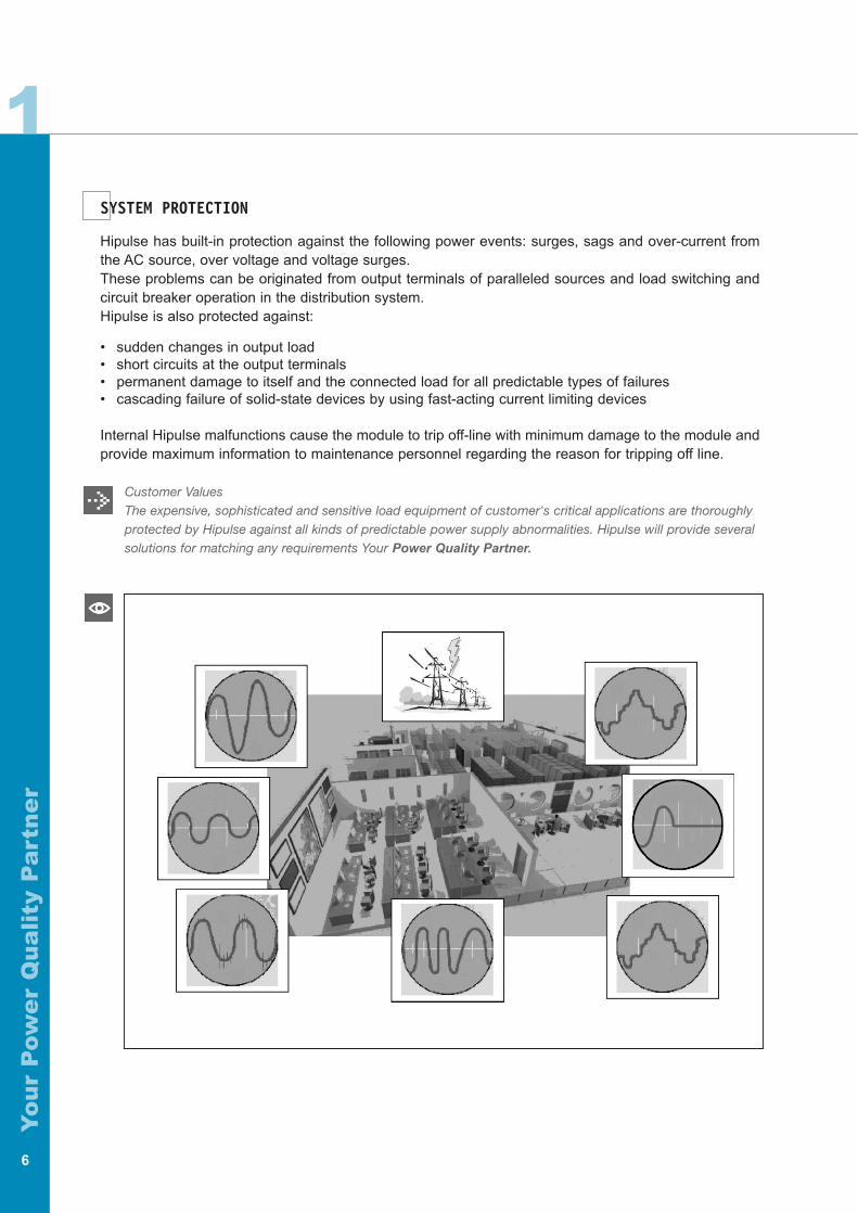
Hipulse has built-in protection against the following power events: surges, sags and over-current fromthe AC source, over voltage and voltage surges.These problems can be originated from output terminals of paralleled sources and load switching andcircuit breaker operation in the distribution system.Hipulse is also protected against:
• sudden changes in output load• short circuits at the output terminals• permanent damage to itself and the connected load for all predictable types of failures• cascading failure of solid-state devices by using fast-acting current limiting devices
Internal Hipulse malfunctions cause the module to trip off-line with minimum damage to the module andprovide maximum information to maintenance personnel regarding the reason for tripping off line.
Customer ValuesThe expensive, sophisticated and sensitive load equipment of customer's critical applications are thoroughly protected by Hipulse against all kinds of predictable power supply abnormalities. Hipulse will provide several solutions for matching any requirements Your Power Quality Partner.
2
Yo
ur
Pow
er
Qu
ali
ty P
art
ne
r
7
MODES OF OPERATION
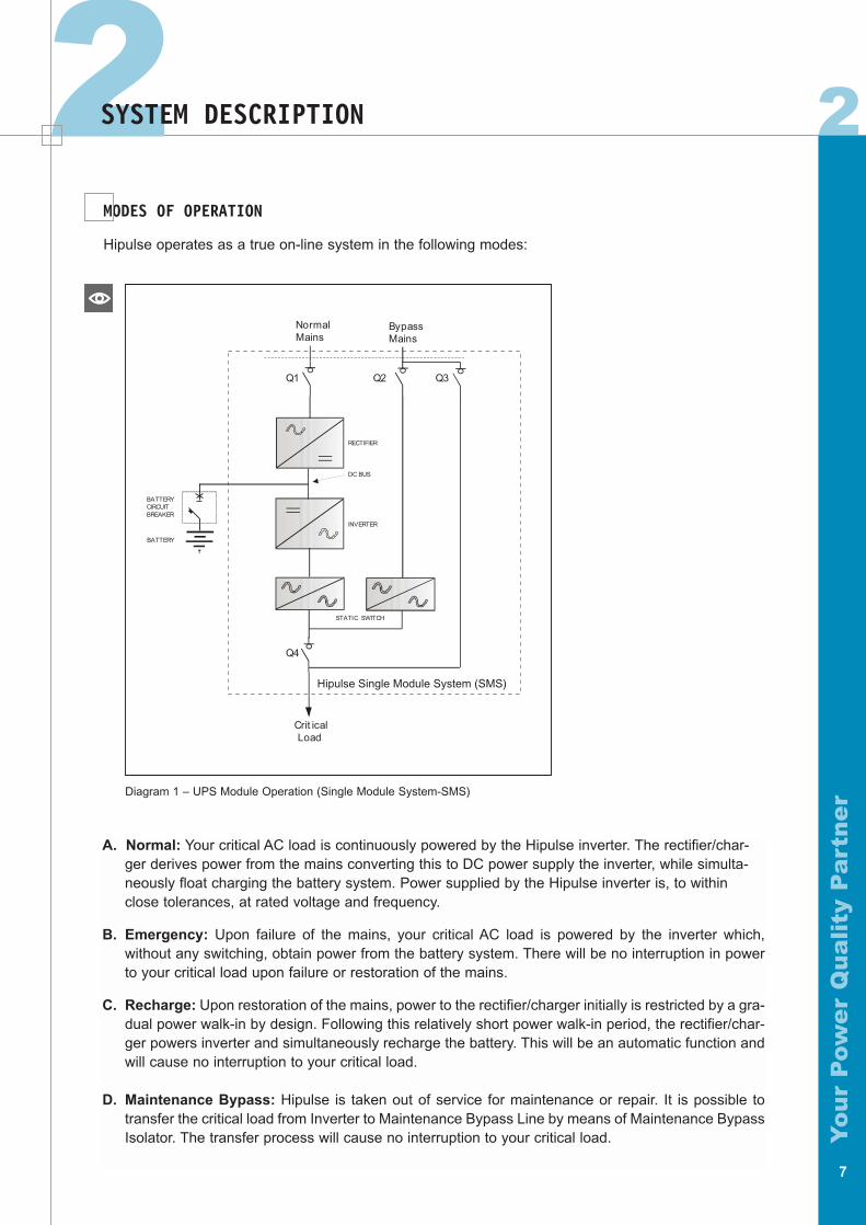
Hipulse operates as a true on-line system in the following modes:
NormalMains
BypassMains
Crit icalLoad
RECTIFIER
INVERTER
STATIC SWITCH
DC BUS
Q1
Q4
Q2 Q3
BATTERYCIRCUITBREAKER
BATTERY
Hipulse Single Module System (SMS)
Diagram 1 – UPS Module Operation (Single Module System-SMS)
A. Normal: Your critical AC load is continuously powered by the Hipulse inverter. The rectifier/char-ger derives power from the mains converting this to DC power supply the inverter, while simulta-neously float charging the battery system. Power supplied by the Hipulse inverter is, to withinclose tolerances, at rated voltage and frequency.
B. Emergency: Upon failure of the mains, your critical AC load is powered by the inverter which,without any switching, obtain power from the battery system. There will be no interruption in powerto your critical load upon failure or restoration of the mains.
C. Recharge: Upon restoration of the mains, power to the rectifier/charger initially is restricted by a gra-dual power walk-in by design. Following this relatively short power walk-in period, the rectifier/char-ger powers inverter and simultaneously recharge the battery. This will be an automatic function andwill cause no interruption to your critical load.
D. Maintenance Bypass: Hipulse is taken out of service for maintenance or repair. It is possible totransfer the critical load from Inverter to Maintenance Bypass Line by means of Maintenance BypassIsolator. The transfer process will cause no interruption to your critical load.
2SYSTEM DESCRIPTION
2
Yo
ur
Pow
er
Qu
ali
ty P
art
ne
r
8
E. Off-Battery: If the battery system only is taken out of service for maintenance, it is disconnectedfrom the rectifier/charger and inverter by means of (an) external disconnect breaker(s). Hipulse willcontinue to function and meet all of the specified steady-state performance criteria, except for thepower outage back-up time capability.
Customer ValuesA. Under normal power conditions, the UPS is an unbeatable source of clean, regulated power to your load. Optionally, by disabling the bypass supply, the UPS can be used as a frequency converter from 50 to 60 Hz and vice-versa.
B. In the "emergency" conditions, the customer gets the value of uninterruptible regulated power supply for aduration of battery autonomy time. This ensures the critical applications to have the most desired regulatedpower even in “mainsfailure” condition.
C. A fully charged battery is the best insurance that your application will be safe in the event of a mains powerfailure. During normal operation bypass thus ensures that the battery is recharging to full ready condition.
D. Critical interventions can be carried out without affecting the power supply to your loads.
E. It provides Additional Safety for your maintenance personnel, giving to your system moreAvailability and Flexibility.
ECOMODE CONFIGURATION
Cost savings can be easily achieved by adopting our exclusive Ecomode configuration.
Customer ValuesEcomode in fact translates into a higher power factor which in turn means more savings.
EcoMode: Less sensitive loads may be fed through the bypass static switch while the bypass mains iswithin an acceptable frequency and voltage window. Failure of the bypass mains to remain within thiswindow results in transfer of your critical load to the Hipulse inverter. The rectifier/charger in either casefloat charges the battery system while its input mains is present.
3
Yo
ur
Pow
er
Qu
ali
ty P
art
ne
r
9
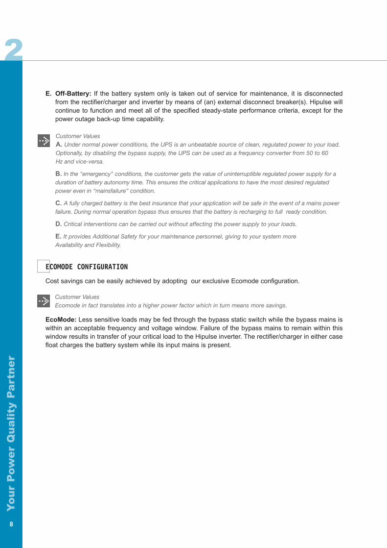
NormalMains
BypassMains
Crit icalLoad
RECTIFIER
INVERTER
STATIC SWITCH
DC BUS
Q1
Q4
Q2 Q3
BATTERYCIRCUITBREAKER
BATTERY
Hipulse Single Module System (SMS)
3CONFIGURATION
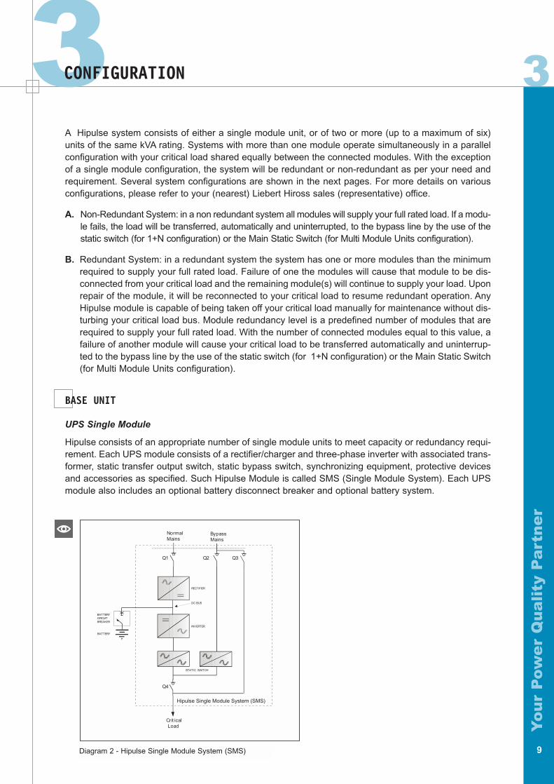
Diagram 2 - Hipulse Single Module System (SMS)
A Hipulse system consists of either a single module unit, or of two or more (up to a maximum of six)units of the same kVA rating. Systems with more than one module operate simultaneously in a parallelconfiguration with your critical load shared equally between the connected modules. With the exceptionof a single module configuration, the system will be redundant or non-redundant as per your need andrequirement. Several system configurations are shown in the next pages. For more details on variousconfigurations, please refer to your (nearest) Liebert Hiross sales (representative) office.
A. Non-Redundant System: in a non redundant system all modules will supply your full rated load. If a modu-le fails, the load will be transferred, automatically and uninterrupted, to the bypass line by the use of thestatic switch (for 1+N configuration) or the Main Static Switch (for Multi Module Units configuration).
B. Redundant System: in a redundant system the system has one or more modules than the minimumrequired to supply your full rated load. Failure of one the modules will cause that module to be dis-connected from your critical load and the remaining module(s) will continue to supply your load. Uponrepair of the module, it will be reconnected to your critical load to resume redundant operation. AnyHipulse module is capable of being taken off your critical load manually for maintenance without dis-turbing your critical load bus. Module redundancy level is a predefined number of modules that arerequired to supply your full rated load. With the number of connected modules equal to this value, afailure of another module will cause your critical load to be transferred automatically and uninterrup-ted to the bypass line by the use of the static switch (for 1+N configuration) or the Main Static Switch(for Multi Module Units configuration).
BASE UNIT
UPS Single Module
Hipulse consists of an appropriate number of single module units to meet capacity or redundancy requi-rement. Each UPS module consists of a rectifier/charger and three-phase inverter with associated trans-former, static transfer output switch, static bypass switch, synchronizing equipment, protective devicesand accessories as specified. Such Hipulse Module is called SMS (Single Module System). Each UPSmodule also includes an optional battery disconnect breaker and optional battery system.
3
Yo
ur
Pow
er
Qu
ali
ty P
art
ne
r
10
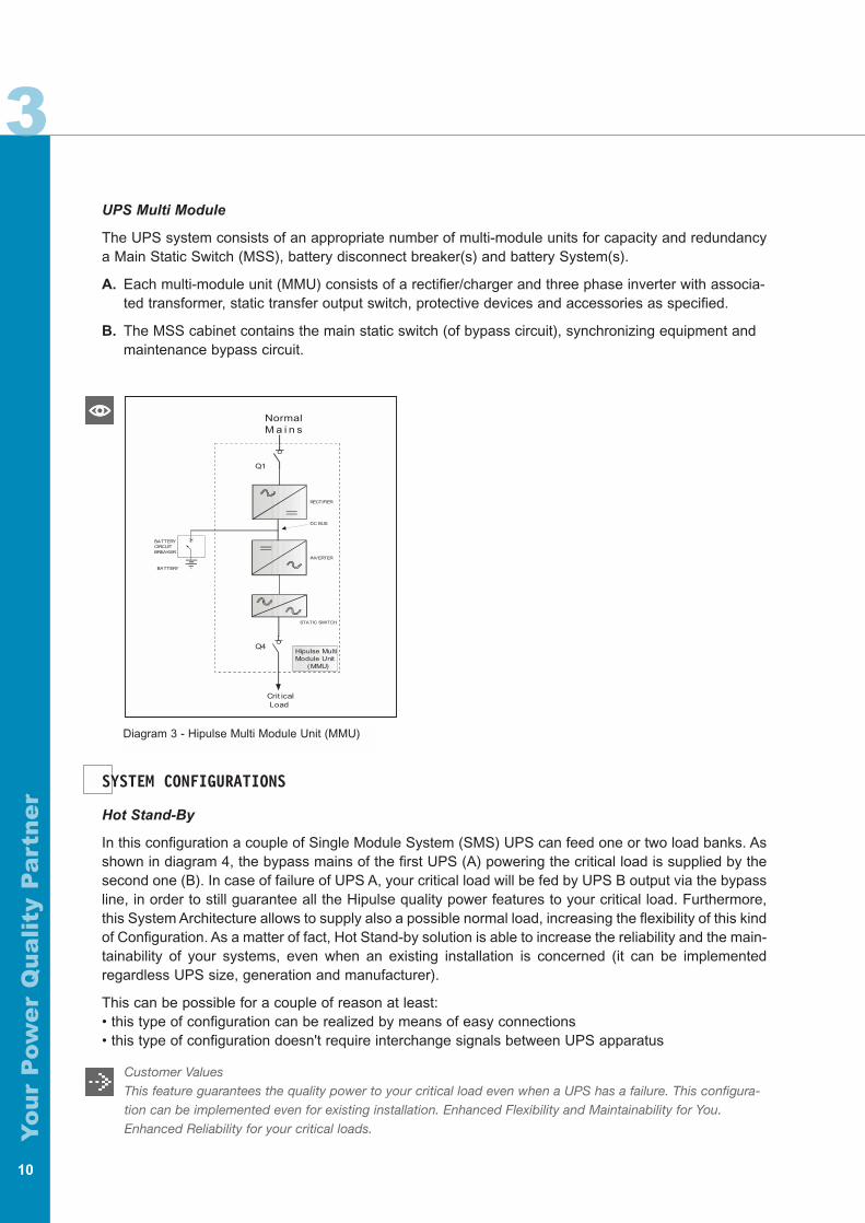
UPS Multi Module
The UPS system consists of an appropriate number of multi-module units for capacity and redundancya Main Static Switch (MSS), battery disconnect breaker(s) and battery System(s).
A. Each multi-module unit (MMU) consists of a rectifier/charger and three phase inverter with associa-ted transformer, static transfer output switch, protective devices and accessories as specified.
B. The MSS cabinet contains the main static switch (of bypass circuit), synchronizing equipment and maintenance bypass circuit.
SYSTEM CONFIGURATIONS
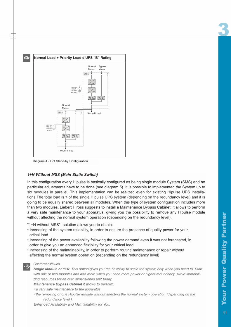
Hot Stand-By
In this configuration a couple of Single Module System (SMS) UPS can feed one or two load banks. Asshown in diagram 4, the bypass mains of the first UPS (A) powering the critical load is supplied by thesecond one (B). In case of failure of UPS A, your critical load will be fed by UPS B output via the bypassline, in order to still guarantee all the Hipulse quality power features to your critical load. Furthermore,this System Architecture allows to supply also a possible normal load, increasing the flexibility of this kindof Configuration. As a matter of fact, Hot Stand-by solution is able to increase the reliability and the main-tainability of your systems, even when an existing installation is concerned (it can be implementedregardless UPS size, generation and manufacturer).
This can be possible for a couple of reason at least:• this type of configuration can be realized by means of easy connections• this type of configuration doesn't require interchange signals between UPS apparatus
Customer ValuesThis feature guarantees the quality power to your critical load even when a UPS has a failure. This configura-tion can be implemented even for existing installation. Enhanced Flexibility and Maintainability for You.Enhanced Reliability for your critical loads.
NormalM a i n s
Crit icalLoad
Hipulse MultiModule Unit
(MMU)
Q1
Q4
BATTERYCIRCUITBREAKER
BATTERY
RECTIFIER
INVERTER
STATIC SWITCH
DC BUS
Diagram 3 - Hipulse Multi Module Unit (MMU)
3
Yo
ur
Pow
er
Qu
ali
ty P
art
ne
r
11
NormalMains
Priorit y load
NormalMains
BypassMains
Normal LoadUPS A
UPS B
BATTERYCIRCUITBREAKER
BATTERY
BATTERYCIRCUITBREAKER
BATTERY
Normal Load + Priority Load ≤ UPS "B" Rating
Diagram 4 - Hot Stand-by Configuration
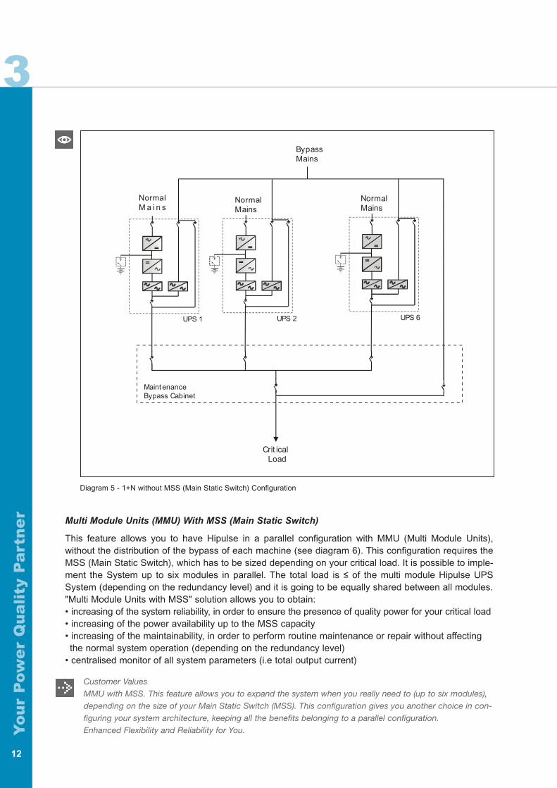
1+N Without MSS (Main Static Switch)
In this configuration every Hipulse is basically configured as being single module System (SMS) and noparticular adjustments have to be done (see diagram 5). It is possible to implemented the System up tosix modules in parallel. This implementation can be realized even for existing Hipulse UPS installa-tions.The total load is ≤ of the single Hipulse UPS system (depending on the redundancy level) and it isgoing to be equally shared between all modules. When this type of system configuration includes morethan two modules, Liebert Hiross suggests to install a Maintenance Bypass Cabinet; it allows to performa very safe maintenance to your apparatus, giving you the possibility to remove any Hipulse modulewithout affecting the normal system operation (depending on the redundancy level).
"1+N without MSS" solution allows you to obtain:• increasing of the system reliability, in order to ensure the presence of quality power for your
crtical load• increasing of the power availability following the power demand even it was not forecasted, in
order to give you an enhanced flexibility for your critical load• increasing of the maintainability, in order to perform routine maintenance or repair without
affecting the normal system operation (depending on the redundancy level)
Customer ValuesSingle Module or 1+N. This option gives you the flexibility to scale the system only when you need to. Start with one or two modules and add more when you need more power or higher redundancy. Avoid immobili-zing resources for an over dimensioned unit today.Maintenance Bypass Cabinet it allows to perform:• a very safe maintenance to the apparatus• the removing of one Hipulse module without affecting the normal system operation (depending on the
redundancy level ).Enhanced Availability and Maintainability for You.
Yo
ur
Pow
er
Qu
ali
ty P
art
ne
r
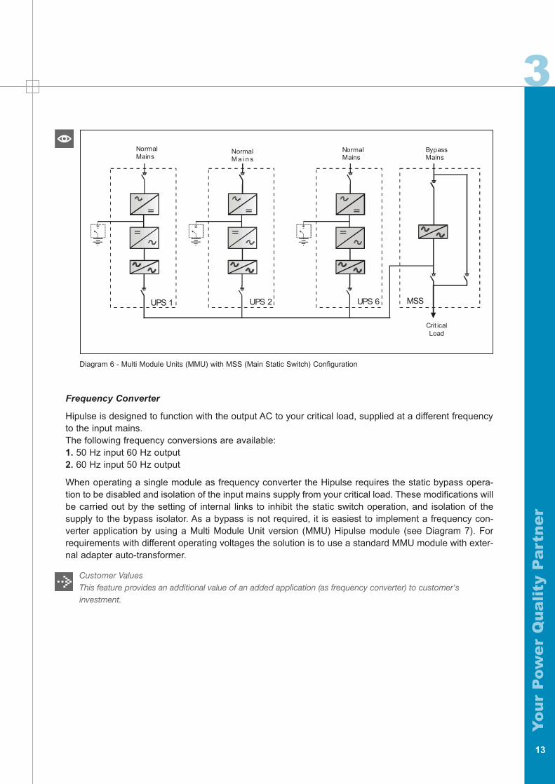
Multi Module Units (MMU) With MSS (Main Static Switch)
This feature allows you to have Hipulse in a parallel configuration with MMU (Multi Module Units),without the distribution of the bypass of each machine (see diagram 6). This configuration requires theMSS (Main Static Switch), which has to be sized depending on your critical load. It is possible to imple-ment the System up to six modules in parallel. The total load is ≤ of the multi module Hipulse UPSSystem (depending on the redundancy level) and it is going to be equally shared between all modules."Multi Module Units with MSS" solution allows you to obtain:• increasing of the system reliability, in order to ensure the presence of quality power for your critical load• increasing of the power availability up to the MSS capacity• increasing of the maintainability, in order to perform routine maintenance or repair without affecting the normal system operation (depending on the redundancy level)
• centralised monitor of all system parameters (i.e total output current)
Customer ValuesMMU with MSS. This feature allows you to expand the system when you really need to (up to six modules),depending on the size of your Main Static Switch (MSS). This configuration gives you another choice in con-figuring your system architecture, keeping all the benefits belonging to a parallel configuration.Enhanced Flexibility and Reliability for You.
12
NormalM a i n s
NormalMains
Crit icalLoad
NormalMains
UPS 1 UPS 2 UPS 6
Maint enanceBypass Cabinet
BypassMains
3
Diagram 5 - 1+N without MSS (Main Static Switch) Configuration
Yo
ur
Pow
er
Qu
ali
ty P
art
ne
r
13
3
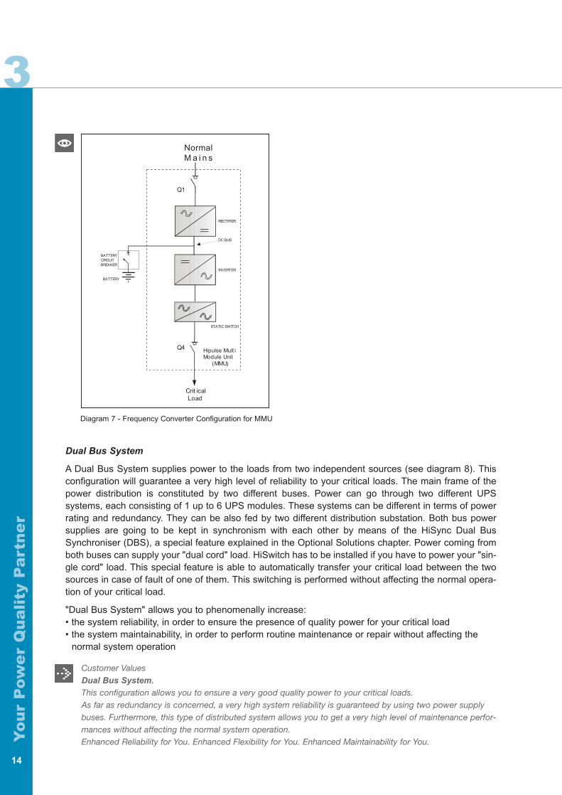
Frequency Converter
Hipulse is designed to function with the output AC to your critical load, supplied at a different frequencyto the input mains.The following frequency conversions are available:1. 50 Hz input 60 Hz output2. 60 Hz input 50 Hz output
When operating a single module as frequency converter the Hipulse requires the static bypass opera-tion to be disabled and isolation of the input mains supply from your critical load. These modifications willbe carried out by the setting of internal links to inhibit the static switch operation, and isolation of thesupply to the bypass isolator. As a bypass is not required, it is easiest to implement a frequency con-verter application by using a Multi Module Unit version (MMU) Hipulse module (see Diagram 7). Forrequirements with different operating voltages the solution is to use a standard MMU module with exter-nal adapter auto-transformer.
Customer Values This feature provides an additional value of an added application (as frequency converter) to customer's investment.
NormalM a i n s
UPS 1 UPS 2 UPS 6 MSS
NormalMains
NormalMains
Crit icalLoad
BypassMains
Diagram 6 - Multi Module Units (MMU) with MSS (Main Static Switch) Configuration
Yo
ur
Pow
er
Qu
ali
ty P
art
ne
r
14
3
Diagram 7 - Frequency Converter Configuration for MMU
NormalM a i n s
Crit icalLoad
Hipulse Mult iModule Unit
(MMU)
Q1
Q4
BATTERYCIRCUITBREAKER
BATTERY
RECTIFIER
INVERTER
STATIC SWITCH
DC BUS
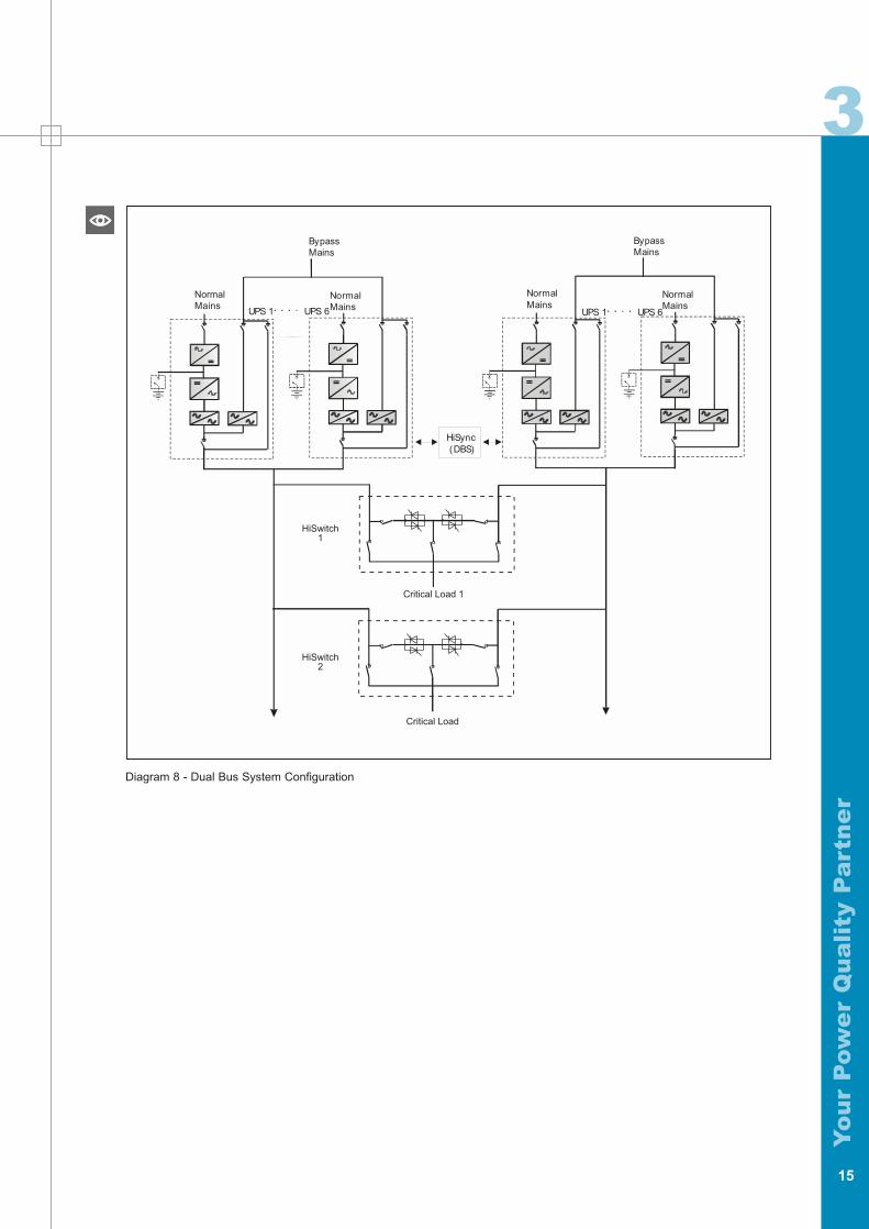
Dual Bus System
A Dual Bus System supplies power to the loads from two independent sources (see diagram 8). Thisconfiguration will guarantee a very high level of reliability to your critical loads. The main frame of thepower distribution is constituted by two different buses. Power can go through two different UPSsystems, each consisting of 1 up to 6 UPS modules. These systems can be different in terms of powerrating and redundancy. They can be also fed by two different distribution substation. Both bus powersupplies are going to be kept in synchronism with each other by means of the HiSync Dual BusSynchroniser (DBS), a special feature explained in the Optional Solutions chapter. Power coming fromboth buses can supply your "dual cord" load. HiSwitch has to be installed if you have to power your "sin-gle cord" load. This special feature is able to automatically transfer your critical load between the twosources in case of fault of one of them. This switching is performed without affecting the normal opera-tion of your critical load.
"Dual Bus System" allows you to phenomenally increase:• the system reliability, in order to ensure the presence of quality power for your critical load• the system maintainability, in order to perform routine maintenance or repair without affecting the
normal system operation
Customer ValuesDual Bus System.
This configuration allows you to ensure a very good quality power to your critical loads.As far as redundancy is concerned, a very high system reliability is guaranteed by using two power supplybuses. Furthermore, this type of distributed system allows you to get a very high level of maintenance perfor-mances without affecting the normal system operation.Enhanced Reliability for You. Enhanced Flexibility for You. Enhanced Maintainability for You.
Yo
ur
Pow
er
Qu
ali
ty P
art
ne
r
15
3
Diagram 8 - Dual Bus System Configuration
NormalMains
Bypass mains
NormalMains
NormalMains
NormalMains
HiSync(DBS)
UPS 1 UPS 6 UPS 1 UPS 6
BypassMains
BypassMains
HiSwitch1
HiSwitch2
Critical Load
Critical Load 1

Yo
ur
Pow
er
Qu
ali
ty P
art
ne
r
16
Yo
ur
Pow
er
Qu
ali
ty P
art
ne
r
17
4RECTIFIER/CHARGER
The term rectifier/charger denotes the solid-state equipment and controls necessary to convert AC toregulated DC for input to the inverter and for charging the battery.
A. Input Current Total Harmonic Distortion: The available filters allow low THD values (as low as 4.0%),as shown in tables 4 and 11.
B. AC Input Current Limiting: The rectifier/charger includes a circuit to limit AC input current to 125% ofthe full input current rating. A secondary circuit provides limiting to 100% on receipt of an externallow voltage signal ( i.e. during generator operation).
C. Battery Charge Current Limiting: The rectifier/charger includes a circuit to limit the battery chargingcurrent to 25% of the input power rating current.
D. Battery Charge Compensation: The rectifier/charger automatically adjusts the battery float chargingvoltage by ± 2 mV per cell per °C when used in conjunction with an optional remote temperature sen-sor.
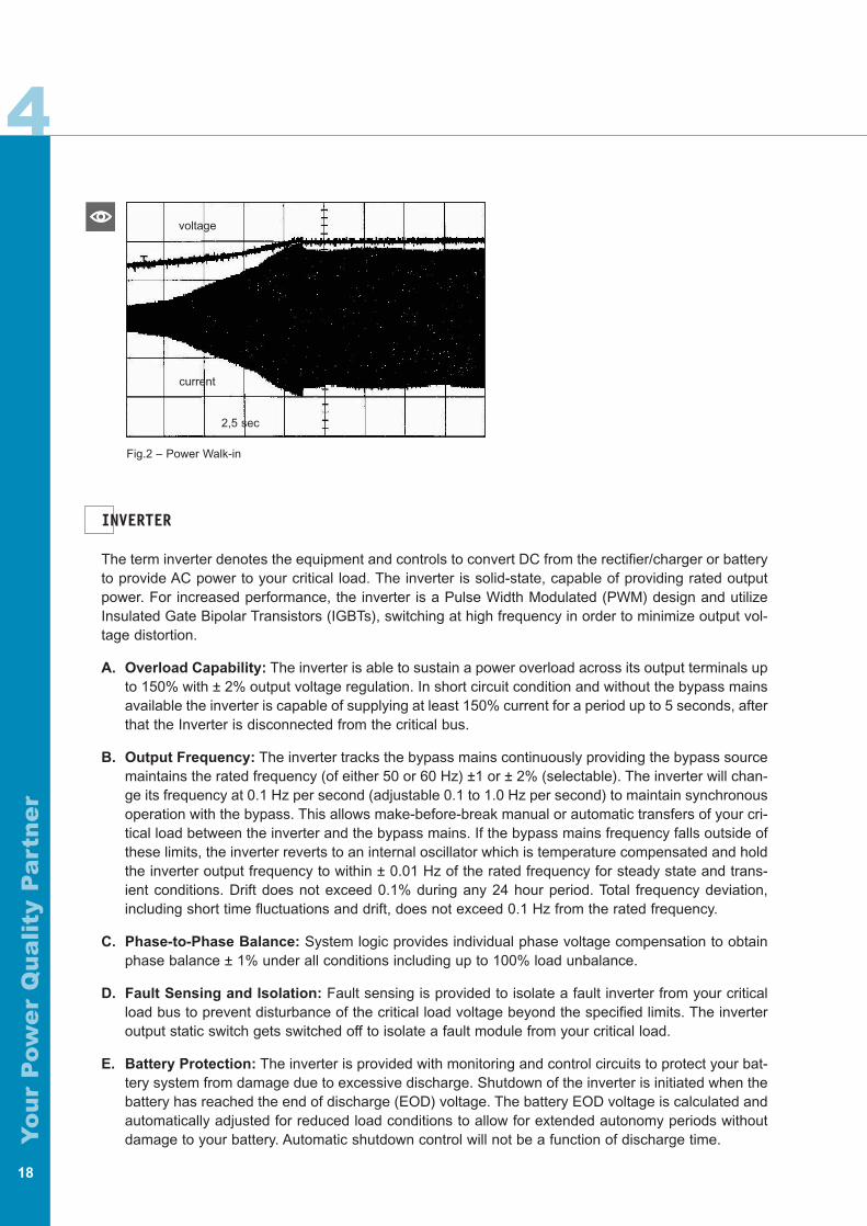
E. Input Power Walk-in: The rectifier/charger provides a feature that limits the total initial power requi-rements to 20% of rated load and gradually increases power up to 100% of full rating over a selec-table time (2 or 10) second time interval.
F. Input Isolator: The rectifier/charger has an input isolator and is fuse protected. The isolator is of theframe size to supply full rated load and recharge the battery at the same time and will withstand ashort circuit current up to 100 kA rms.
G. Fuse Protection: Each AC phase is individually fused with fast acting fuses so that loss of any semi-conductor will not cause cascading failures.
H. DC Filter: The rectifier/charger has an output filter to minimize ripple current into the battery. The ACripple voltage of the rectifier DC output does not exceed 1% rms of the voltage float. The filter is ade-quate to ensure that the DC output of the rectifier/charger will meet the input requirements of theinverter without the battery connected.
I. Battery recharge: In addition to supplying power to your critical load, the rectifier/charger is capableof producing battery charging current sufficient to replace 95% of the battery discharge power withinten (10) times the discharge period. This for batteries with back-up times up to approx. 1,5 h. Afterthe battery is recharged, the rectifier/charger maintains the battery at full charge until the next emer-gency operation.
Customer ValuesA. With lower input THD value, the customer gains in term of lower electricity bills and lower upstream powerpollution. Such gains are really tangible for higher ranges of UPS (i.e. > 200 kVA). Below that rating, it is notreally worth mentioning.C-D. Such controls are valuable additional protections for the battery and its life duration. All the described fea-tures will phenomenally improve it. Investment Protection for You.E. As shown in the picture (fig. 2), the current smoothly follows the sudden voltage variation. The control on thecurrent itself is extremely important and allows a very accurate power walk-in.H. Even a small AC component circulating in the battery will significantly heat it up and shorten its life. Hipulseis built with no compromises regarding the protection of all the components.Investment Protection for You.I. A significantly oversized rectifier is able to guarantee a good recharge time (10 times the discharge period) tothe battery in every condition and will reduce the risk of having it not fully charged in case of need. It is able toguarantee as much as 25% of the nominal current dedicated to the battery recharge also at full load.
4COMPONENTS
4
Yo
ur
Pow
er
Qu
ali
ty P
art
ne
r
18
Fig.2 – Power Walk-in
voltage
2,5 sec
current
INVERTER
The term inverter denotes the equipment and controls to convert DC from the rectifier/charger or batteryto provide AC power to your critical load. The inverter is solid-state, capable of providing rated outputpower. For increased performance, the inverter is a Pulse Width Modulated (PWM) design and utilizeInsulated Gate Bipolar Transistors (IGBTs), switching at high frequency in order to minimize output vol-tage distortion.
A. Overload Capability: The inverter is able to sustain a power overload across its output terminals upto 150% with ± 2% output voltage regulation. In short circuit condition and without the bypass mainsavailable the inverter is capable of supplying at least 150% current for a period up to 5 seconds, afterthat the Inverter is disconnected from the critical bus.
B. Output Frequency: The inverter tracks the bypass mains continuously providing the bypass sourcemaintains the rated frequency (of either 50 or 60 Hz) ±1 or ± 2% (selectable). The inverter will chan-ge its frequency at 0.1 Hz per second (adjustable 0.1 to 1.0 Hz per second) to maintain synchronousoperation with the bypass. This allows make-before-break manual or automatic transfers of your cri-tical load between the inverter and the bypass mains. If the bypass mains frequency falls outside ofthese limits, the inverter reverts to an internal oscillator which is temperature compensated and holdthe inverter output frequency to within ± 0.01 Hz of the rated frequency for steady state and trans-ient conditions. Drift does not exceed 0.1% during any 24 hour period. Total frequency deviation,including short time fluctuations and drift, does not exceed 0.1 Hz from the rated frequency.
C. Phase-to-Phase Balance: System logic provides individual phase voltage compensation to obtainphase balance ± 1% under all conditions including up to 100% load unbalance.
D. Fault Sensing and Isolation: Fault sensing is provided to isolate a fault inverter from your criticalload bus to prevent disturbance of the critical load voltage beyond the specified limits. The inverteroutput static switch gets switched off to isolate a fault module from your critical load.
E. Battery Protection: The inverter is provided with monitoring and control circuits to protect your bat-tery system from damage due to excessive discharge. Shutdown of the inverter is initiated when thebattery has reached the end of discharge (EOD) voltage. The battery EOD voltage is calculated andautomatically adjusted for reduced load conditions to allow for extended autonomy periods withoutdamage to your battery. Automatic shutdown control will not be a function of discharge time.
Yo
ur
Pow
er
Qu
ali
ty P
art
ne
r
19
4
Customer ValuesA. High overload capability (current overload at nominal voltage) allows the customer to avoid the UPS over-sizing and let the UPS absorb basically peak power requirement for a specified duration to enhance availability.Reduced initial investment for You.B. The possibility to modify the behavior of the UPS according to the frequency fluctuations value, makes theUPS extremely flexible (it can be used as a frequency converter as well). User flexibility for You.C. This lets you distribute the load between the phases absolutely as you require to do, without any worry forUPS or balancing the loads. User flexibility for You.D. This feature allows to avoid damaging for your critical load. Investment Protection for You.E. This feature offers an extra protection to your battery preventing dangerous situations that could seriouslydamage it.Investment Protection for You.
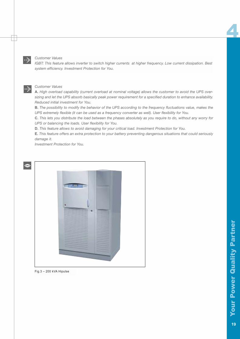
Fig.3 – 200 kVA Hipulse
Customer ValuesIGBT: This feature allows inverter to switch higher currents at higher frequency. Low current dissipation. Bestsystem efficiency. Investment Protection for You.
4
Yo
ur
Pow
er
Qu
ali
ty P
art
ne
r
20
BypassM a i n s
Crit icalLoad
Q1
Q3
FromUPS
Q2
MSS
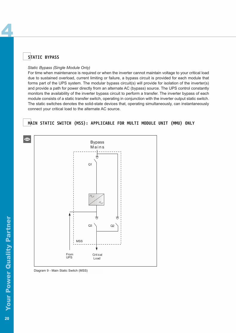
Diagram 9 - Main Static Switch (MSS)
STATIC BYPASS
Static Bypass (Single Module Only)For time when maintenance is required or when the inverter cannot maintain voltage to your critical loaddue to sustained overload, current limiting or failure, a bypass circuit is provided for each module thatforms part of the UPS system. The modular bypass circuit(s) will provide for isolation of the inverter(s)and provide a path for power directly from an alternate AC (bypass) source. The UPS control constantlymonitors the availability of the inverter bypass circuit to perform a transfer. The inverter bypass of eachmodule consists of a static transfer switch, operating in conjunction with the inverter output static switch.The static switches denotes the solid-state devices that, operating simultaneously, can instantaneouslyconnect your critical load to the alternate AC source.
MAIN STATIC SWITCH (MSS): APPLICABLE FOR MULTI MODULE UNIT (MMU) ONLY
Yo
ur
Pow
er
Qu
ali
ty P
art
ne
r
21
4The UPS system is provided with a separate free-standing bypass main static switch for time when main-tenance is required or when the inverter cannot maintain voltage to your critical load due to sustained over-load, current limiting or failure. The MSS static bypass circuit provides for isolation of the inverter(s) andprovides a path for power directly from an alternate AC (bypass) source. The UPS control constantly moni-tors the availability of the inverter bypass circuit to perform a transfer. The static switch of MSS operates inconjunction with the inverter output static switch. The static switches denote the solid-state devices that,operating simultaneously, can instantaneously connect your critical load to the alternate AC source.
A. Manual Load Transfers: A manual load transfer between the inverter output and the alternate ACsource is initiated from the control panel. A means to perform manual transfers remotely is madeavailable as an optional extra.
B. Automatic Load Transfers: An automatic load transfer between the inverter output and the alternateAC source is initiated if an overload or short circuit condition is sustained for a period in excess ofthe inverter output capability or due to a failure that would affect output voltage. Transfers caused byoverloads will initiate an automatic retransfer of your critical load back to the inverter only after yourload has returned to a level within the rating of the inverter source.
C. Back-feed Protection: The static bypass is provided with detection and control circuits, to be used inconjunction with external automatic switch-gear, in order to disconnect the bypass line in the eventof a short-circuit being detected in the solid-state devices that form the bypass static transfer switch.The purpose of this requirement is to prevent the risk of electrical shock on your distribution systemwhen the normal source of power is disconnected or has failed.
Customer ValuesA It allows to choose how supplying your critical load, depending on your need. Enhanced Availability andFlexibility for your critical load.B It allows to protect either your UPS or your critical load in case of output failure. Investment Protection for You.C Back-feed protection system is an important extra safety tool to protect the life of everyone working on themachine, guaranteeing you also in case of an internal short circuit. This feature permits a very safe manual ope-ration on every condition. Additional Safety and Investment Protection for You.
MAINTENANCE BYPASS
Internal Maintenance Bypass (Single Module Only)A fully rated bypass circuit is fitted on all Single Module Systems (SMS) to provide an alternative path forpower flow from the alternate AC supply to your critical load for the purpose of maintaining the UPS whenit is completely powered down.
Customer ValuesInternal Maintenance Bypass
It allows to perform maintenance or repair without affecting power for your critical load. Enhanced Availability for You.
MSS Maintenance Bypass (Multi Module Only)A fully rated bypass circuit is fitted in the MSS to provide an alternative path for power flow from the alternate AC
supply to your critical load for the purpose of maintaining all the Multi Module Units (MMU) while they are comple-
tely powered down.
Customer ValuesMSS Maintenance Bypass
It allows to perform maintenance or repair to your system without affecting the power supply to the load.Enhanced Availability for You

Yo
ur
Pow
er
Qu
ali
ty P
art
ne
r
22
Yo
ur
Pow
er
Qu
ali
ty P
art
ne
r
23
5ENVIRONMENTAL CONDITIONS
Operating Ambient TemperatureUPS: 0 °C up to 40 °C without de-rating.Battery: 25 °C for optimum battery performance.
Storage/Transport Ambient TemperatureUPS: -25 °C up to 70 °C.Battery: 20 °C for optimum battery storage.
Relative Humidity0 up to 95%, non-condensing.It is assumed that, maximums of both ambient temperature and relative humidity shall not occur simul-taneously.
AltitudeOperating: up to 1000 m above mean sea level (MSL) without de-rating (de-rate by 1% per 100 m bet-ween 1000 and 2000 meters above MSL).Storage: up to 1000 m above mean sea level for continuous storage. Up to 15000 m above mean sealevel for air transportation for a flight duration not exceeding 16 hours.
Electrostatic DischargeHipulse is able to withstand an electrostatic discharge compliant to IEC 801-2 level 4 (15 kV throughair, 8 kV contact) without damage to equipment or your connected load.
MECHANICAL SPECIFICATION
MaterialsAll materials for the Hipulse are of current manufacture, high grade and have not been in prior serviceexcept as required during factory testing. All active electronic devices are solid-state. Control logic andfuses are physically isolated from power train components to ensure operator safety and protection fromheat. All electronic components are accessible from the front without removing sub-assemblies for ser-vice access.
WiringWiring practices, materials and coding in Hipulse are in accordance with the requirements of IEC.All electrical power connections are torqued to the required value and marked with a visual indicator.Provisions are made in the cabinets to permit installation of input, output, and external control cabling.Provision are also made for either top or bottom access, allowing for adequate cable bend radius, to theinput and output connections.
ConstructionHipulse is housed in an IP20 enclosure (even with front door opened condition), designed for floor moun-ting. Hipulse is structurally adequate and have provisions for hoisting, jacking and forklift handling.Maximum cabinet height is 1.9 meters.
Cable EntryCables can enter for Hipulse UPS and battery cabinet either from below or through either side. Sideentry is made possible by removing grille panels fitted in the side panel to reveal the cable entry holes.This cable entry method allows cables to pass from one module to the other when positioned side-by-side.When selecting the power cables for side entry to a module located on a solid floor, considerationmust be given to the minimum permissible radius of the proposed cables to ensure that they can be fas-hioned to reach the UPS connection bus bars.
5PERFORMANCE REQUIREMENTS
5
Yo
ur
Pow
er
Qu
ali
ty P
art
ne
r
24
CoolingAdequate ventilation is provided in Hipulse to ensure that all components are operated well within tem-perature ratings. Temperature sensors are provided to monitor UPS internal temperature. Upon detec-tion of temperatures in excess of manufacturer’s recommendations, the sensors actuate audible andvisual alarms to be sounded at the UPS control panel. A separate room ambient temperature sensor canbe optional provided to allow control of the battery charging voltage with change of temperature. No clea-rance is required at the rear of the Hipulse UPS for the purpose of ventilation.
Customer ValuesCooling This feature allows components to operate without stressing resulting from high temperature.Investment Protection for You.No clearance. This is important because it allows to leave no more room around UPS for cooling purpose.Space saving. Low cost of ownership for You.
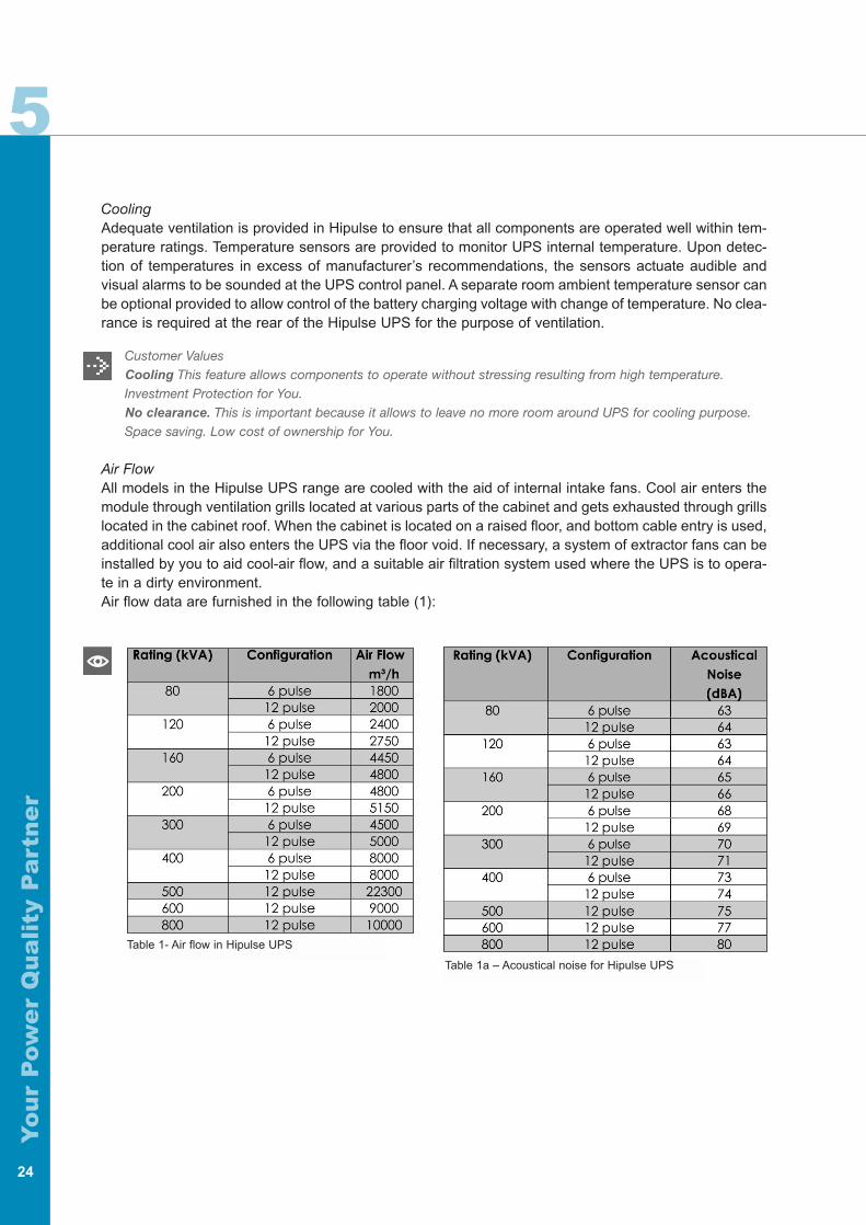
Air FlowAll models in the Hipulse UPS range are cooled with the aid of internal intake fans. Cool air enters themodule through ventilation grills located at various parts of the cabinet and gets exhausted through grillslocated in the cabinet roof. When the cabinet is located on a raised floor, and bottom cable entry is used,additional cool air also enters the UPS via the floor void. If necessary, a system of extractor fans can beinstalled by you to aid cool-air flow, and a suitable air filtration system used where the UPS is to opera-te in a dirty environment.Air flow data are furnished in the following table (1):
Table 1- Air flow in Hipulse UPS
Table 1a – Acoustical noise for Hipulse UPS
Yo
ur
Pow
er
Qu
ali
ty P
art
ne
r
25
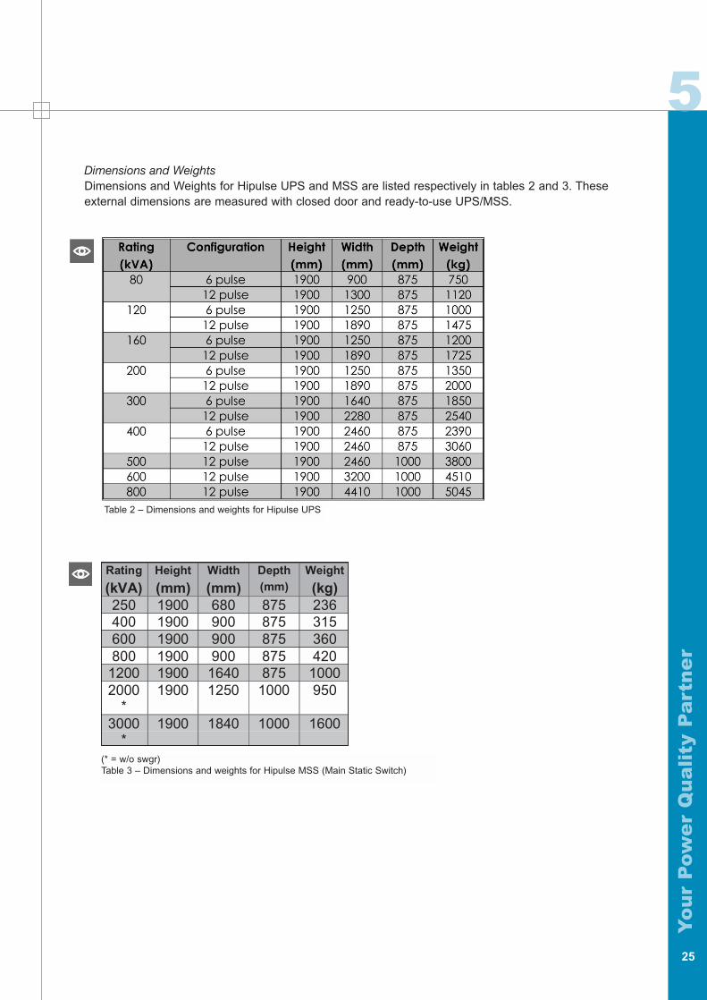
5Dimensions and Weights Dimensions and Weights for Hipulse UPS and MSS are listed respectively in tables 2 and 3. Theseexternal dimensions are measured with closed door and ready-to-use UPS/MSS.
Table 2 – Dimensions and weights for Hipulse UPS
(* = w/o swgr)Table 3 – Dimensions and weights for Hipulse MSS (Main Static Switch)
Rating
(kVA)Height
(mm)Width
(mm)Depth(mm)
Weight
(kg)250 1900 680 875 236400 1900 900 875 315600 1900 900 875 360800 1900 900 875 420
1200 1900 1640 875 10002000
*1900 1250 1000 950
3000*
1900 1840 1000 1600
5
Yo
ur
Pow
er
Qu
ali
ty P
art
ne
r
26
HIPULSE UPS MODULE AC INPUT
Hipulse UPS is VFI classified (according to CEMEP / ENV 50091-3) producing an output waveformthat is independent of both the input supply frequency and voltage.
UPS Module AC Input
A. Voltage Range: ±15%.
B. Frequency Range: 45 ÷ 65 Hz without adjustment.
C. In-rush Current Limiting: 20% up to 100% of full rated current over 10 seconds.
D. Power factor: Minimum of 0.8 lagging at full load with nominal input voltage (can be increased up to0.93 lagging with optional input tuned filter). Input power factor for 12 pulse modules with input tunedfilter permits operation with the filter connected down to 10% rated load without the input power fac-tor going leading.
E. 2-Step Input Current Limit: Maximum of 125% normal full load input current (100% for generator ope-ration).
F. Temperature Compensated Charging: Above 25 °C the battery charge voltage will reduce by 2 mVper cell per °C in order to optimize on your battery lifetime.
G. Current Distortion: The following table (4 and 11) shows the input current, THD values and the realharmonic distortion value at full load.
H. Battery Discharge Test: Your battery will be periodically tested in order to check the components sta-tus and health of its components.
Customer ValuesA-B. This large voltage window allows the rectifier to provide energy to the inverter also in critical conditions,preserving the battery, whose life is proportional to the number of charge-discharge cycles.This large frequency tolerance allows the UPS to be fed by a generator being able to follow its frequencywithout any problem. Investment Protection for You and Enhanced Availability for your critical loads.C. Such a progressive and flexible power transfer is a very valuable feature when the UPS is used togetherwith or without a generator.D. A properly mix of features (6-12 pulse or input filter utilizing) allows to obtain the best solution for yourneed. Enhanced Availability for You.E. This feature gives you more availability, allowing you to limit input current in case of generator operation.F. Investment Protection for You.G. Low THD values permit Hipulse machines to disturb not any load in parallel being so a clean and not “pol-luting” power device.H. A periodic test will ensure the battery works as designed before the system needs it. Enhanced SystemAvailability.
Yo
ur
Pow
er
Qu
ali
ty P
art
ne
r
27
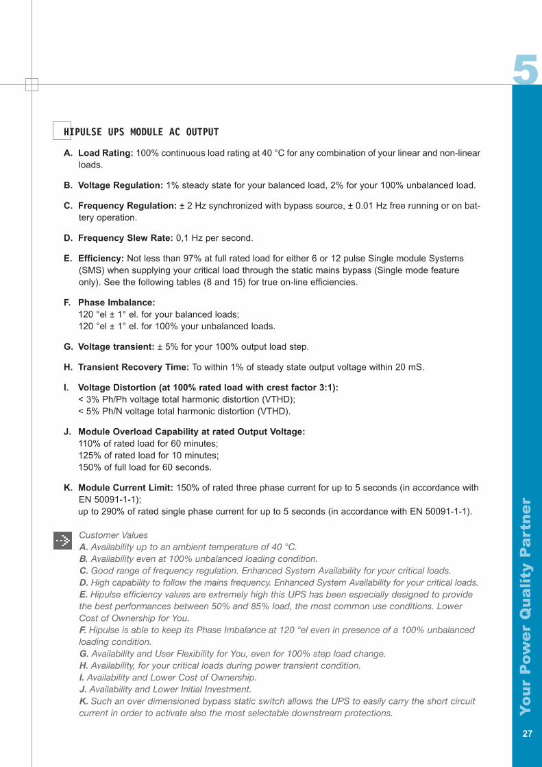
5HIPULSE UPS MODULE AC OUTPUT
A. Load Rating: 100% continuous load rating at 40 °C for any combination of your linear and non-linearloads.
B. Voltage Regulation: 1% steady state for your balanced load, 2% for your 100% unbalanced load.
C. Frequency Regulation: ± 2 Hz synchronized with bypass source, ± 0.01 Hz free running or on bat-tery operation.
D. Frequency Slew Rate: 0,1 Hz per second.
E. Efficiency: Not less than 97% at full rated load for either 6 or 12 pulse Single module Systems(SMS) when supplying your critical load through the static mains bypass (Single mode featureonly). See the following tables (8 and 15) for true on-line efficiencies.
F. Phase Imbalance:120 °el ± 1° el. for your balanced loads;120 °el ± 1° el. for 100% your unbalanced loads.
G. Voltage transient: ± 5% for your 100% output load step.
H. Transient Recovery Time: To within 1% of steady state output voltage within 20 mS.
I. Voltage Distortion (at 100% rated load with crest factor 3:1):< 3% Ph/Ph voltage total harmonic distortion (VTHD);< 5% Ph/N voltage total harmonic distortion (VTHD).
J. Module Overload Capability at rated Output Voltage:110% of rated load for 60 minutes;125% of rated load for 10 minutes; 150% of full load for 60 seconds.
K. Module Current Limit: 150% of rated three phase current for up to 5 seconds (in accordance withEN 50091-1-1);up to 290% of rated single phase current for up to 5 seconds (in accordance with EN 50091-1-1).
Customer ValuesA. Availability up to an ambient temperature of 40 °C.B. Availability even at 100% unbalanced loading condition.C. Good range of frequency regulation. Enhanced System Availability for your critical loads.D. High capability to follow the mains frequency. Enhanced System Availability for your critical loads.E. Hipulse efficiency values are extremely high this UPS has been especially designed to providethe best performances between 50% and 85% load, the most common use conditions. LowerCost of Ownership for You.F. Hipulse is able to keep its Phase Imbalance at 120 °el even in presence of a 100% unbalancedloading condition.G. Availability and User Flexibility for You, even for 100% step load change.H. Availability, for your critical loads during power transient condition.I. Availability and Lower Cost of Ownership.J. Availability and Lower Initial Investment.K. Such an over dimensioned bypass static switch allows the UPS to easily carry the short circuitcurrent in order to activate also the most selectable downstream protections.
5
Yo
ur
Pow
er
Qu
ali
ty P
art
ne
r
28
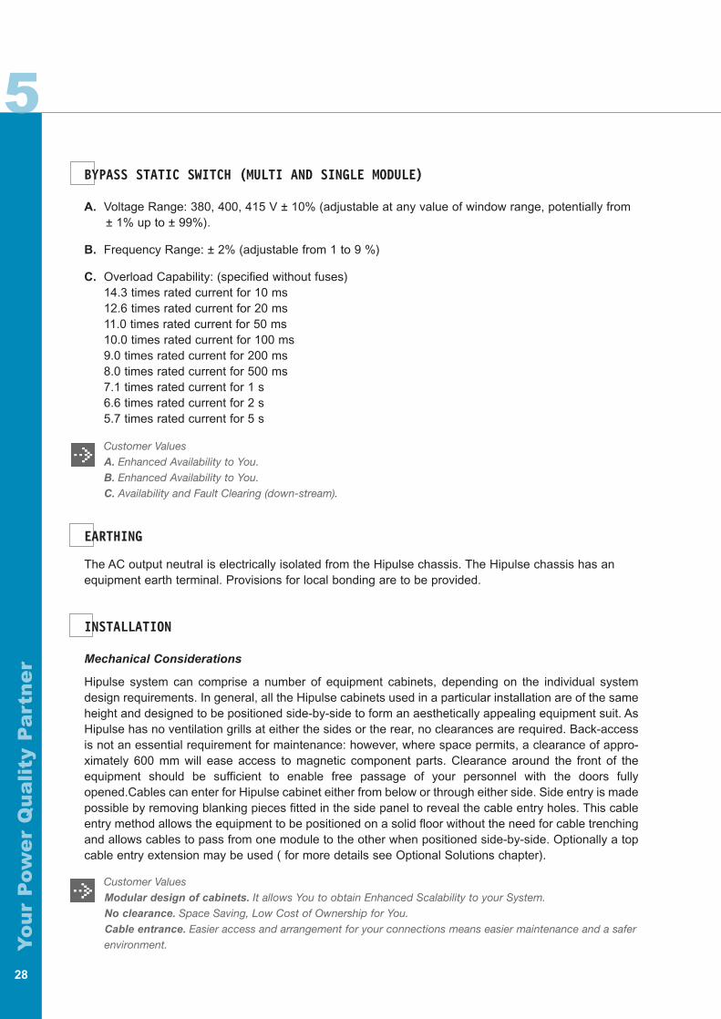
BYPASS STATIC SWITCH (MULTI AND SINGLE MODULE)
A. Voltage Range: 380, 400, 415 V ± 10% (adjustable at any value of window range, potentially from± 1% up to ± 99%).
B. Frequency Range: ± 2% (adjustable from 1 to 9 %)
C. Overload Capability: (specified without fuses)14.3 times rated current for 10 ms12.6 times rated current for 20 ms11.0 times rated current for 50 ms10.0 times rated current for 100 ms9.0 times rated current for 200 ms8.0 times rated current for 500 ms7.1 times rated current for 1 s6.6 times rated current for 2 s5.7 times rated current for 5 s
Customer ValuesA. Enhanced Availability to You.B. Enhanced Availability to You.C. Availability and Fault Clearing (down-stream).
EARTHING
The AC output neutral is electrically isolated from the Hipulse chassis. The Hipulse chassis has anequipment earth terminal. Provisions for local bonding are to be provided.
INSTALLATION
Mechanical Considerations
Hipulse system can comprise a number of equipment cabinets, depending on the individual systemdesign requirements. In general, all the Hipulse cabinets used in a particular installation are of the sameheight and designed to be positioned side-by-side to form an aesthetically appealing equipment suit. AsHipulse has no ventilation grills at either the sides or the rear, no clearances are required. Back-accessis not an essential requirement for maintenance: however, where space permits, a clearance of appro-ximately 600 mm will ease access to magnetic component parts. Clearance around the front of theequipment should be sufficient to enable free passage of your personnel with the doors fullyopened.Cables can enter for Hipulse cabinet either from below or through either side. Side entry is madepossible by removing blanking pieces fitted in the side panel to reveal the cable entry holes. This cableentry method allows the equipment to be positioned on a solid floor without the need for cable trenchingand allows cables to pass from one module to the other when positioned side-by-side. Optionally a topcable entry extension may be used ( for more details see Optional Solutions chapter).
Customer ValuesModular design of cabinets. It allows You to obtain Enhanced Scalability to your System.No clearance. Space Saving, Low Cost of Ownership for You.Cable entrance. Easier access and arrangement for your connections means easier maintenance and a saferenvironment.
5
Yo
ur
Pow
er
Qu
ali
ty P
art
ne
r
29
Electrical Installation
Hipulse requires both "power" and "control" cabling once it has been mechanically installed. All "control"cables, whether screened or not, should be run separate from the power cables in metal ducts whichare electrically bonded to the metalwork of the cabinets to which they are connected. The rectifier input,bypass, output and battery power cables (all require lug type terminations) are connected to bus barssituated in the bottom side of the cabinets. Terminal blocks are used for connecting the control cablesto the battery circuit breaker, external emergency stop facility, external OFF inverter, external Bypass,etc. The safety earth bus bar is located near the input and output power supply connections.
Customer valuesBus bars and terminal blocks. This feature allows to reach a User Friendly access and arrangement."Control" and "Power" cables. They have been designed to follow different paths inside Hipulse, in order toeliminate disturbance inducted by "power" cables. Enhanced Reliability and Availability to your System.
TECHNICAL DATA
General Notes
There are some UPS parameters (e.g. Input current THD, Efficiency, etc.) that could be influenced byyour application and/or environmental conditions. In fact, a mix of circumstances as mains impedancelevel, harmonic pollution caused by power electronics based equipment, the different quality of powergenerators, transmission lines, substations, distribution lines (due to the different utility companies), loa-ding conditions like % loading, nature of load, characteristics of the load, starting behavior of the load,number of start/stop per day etc. make it difficult to state the exact data for these above parameters ofthe UPS after its installation. All these factors have led our Engineering & Development Department tobe more prudent in data declaration. The data available on Hipulse Guide are the close-to-accuratevalues. We suggest you to please contact our nearest sales office/representative in order to get morerelevant data related to your plant and application in particular.
5
Yo
ur
Pow
er
Qu
ali
ty P
art
ne
r
30
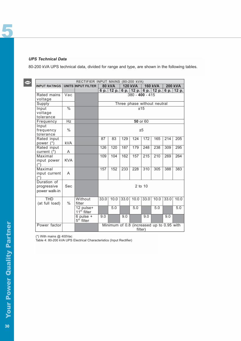
80 kVA 120 kVA 160 kVA 200 kVAINPUT RATINGS UNITS INPUT FILTER
6 p. 12 p. 6 p. 12 p. 6 p. 12 p. 6 p. 12 p.Rated mainsvoltage
Vac 380 - 400 - 415
Supply Three phase without neutralInputvoltagetolerance
% ±15
Frequency Hz 50 or 60Inputfrequencytolerance
% ±5
Rated inputpower (*) kVA
87 83 129 124 172 165 214 205
Rated inputcurrent (*) A
126 120 187 179 248 238 309 295
Maximalinput power(*)
KVA109 104 162 157 215 210 269 264
Maximalinput current(*)
A157 152 233 228 310 305 388 383
Duration ofprogressivepower walk-in
Sec 2 to 10
Withoutfilter
33.0 10.0 33.0 10.0 33.0 10.0 33.0 10.0
12 pulse+11th filter
5.0 5.0 5.0 5.0
THD(at full load) %
6 pulse +5th filter
9.0 9.0 9.0 9.0
Power factor Minimum of 0.8 (increased up to 0.95 withfilter)
RECTIFIER INPUT MAINS (80-200 kVA)
UPS Technical Data
80-200 kVA UPS technical data, divided for range and type, are shown in the following tables.
(*) With mains @ 400VacTable 4: 80-200 kVA UPS Electrical Characteristics (Input Rectifier)
5
Yo
ur
Pow
er
Qu
ali
ty P
art
ne
r
31
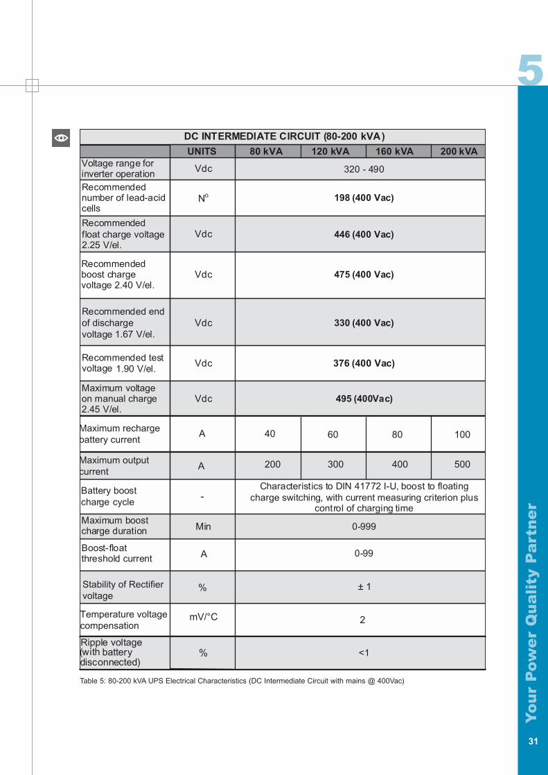
Table 5: 80-200 kVA UPS Electrical Characteristics (DC Intermediate Circuit with mains @ 400Vac)
200 kVAUNITS 80 kVA 120 kVA
320 - 490
160 kVA
Vdc
No
Vdc
Vdc
Vdc
Vdc
Vdc
Voltage range forinverter operationRecommendednumber of lead-acicells
Recommendedfloat charge voltage2.25 V/el.
Maximum voltageon manual charge2.45 V/el.
198 (400 Vac)
446 (400 Vac)
475 (400 Vac)
330 (400 Vac)
376 (400 Vac)
495 (400Vac)
DC INTERMEDIATE CIRCUIT (80-200 kVA)
d
Recommendedboost chargevoltage 2.40 V/el.
1.90 V/el.Recommended testvoltage
Recommended endof dischargevoltage 1.67 V/el.
disconnected)battery(with
Maximum boostcharge duration Min
A
Battery boostcharge cycle
Boost-floatthreshold current
Characteristics to DIN 41772 I-U, boost to floatingcharge switching, with current measuring criterion plus
control of charging time
0-999
0-99
-
% <1Ripple voltage
Stability of Rectifiervoltage
% ± 1
Temperature voltagecompensation
mV/°C 2
Maximum rechargebattery current
Maximum outputcurrent
A 40 60 80 100
200 300 400 500A
5
Yo
ur
Pow
er
Qu
ali
ty P
art
ne
r
32
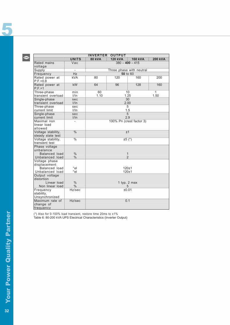
(*) Also for 0-100% load transient, restore time 20ms to ±1% Table 6: 80-200 kVA UPS Electrical Characteristics (Inverter Output)
INVERTER OUTPUTUNITS 80 kVA 120 kVA 160 kVA 200 kVA
Rated mainsvoltage
Vac 380 – 400 – 415
Supply - Three phase with neutralFrequency Hz 50 to 60Rated power atP.F.=0.8
kVA 80 120 160 200
Rated power atP.F.=1
kW 64 96 128 160
Three-phasetransient overload
minI/In
601.10
101.25
11.50
Single-phasetransient overload
secI/In
302.00
Three-phasecurrent limit
secI/In
51.5
Single-phasecurrent limit
secI/In
52.9
Maximal nonlinear loadallowed
- 100% Pn (crest factor 3)
Voltage stability,steady state test
% ±1
Voltage stability,transient test
% ±5 (*)
Phase voltageunbalance
Balanced loadUnbalanced load
%%
12
Voltage phasedisplacement
Balanced loadUnbalanced load
°el°el
120±1120±1
Output voltagedistortion
Linear loadNon linear load
%%
1 typ, 2 max5
Frequencystability,Unsynchronized
Hz/sec ±0.01
Maximum rate ofchange offrequency
Hz/sec 0.1
5
Yo
ur
Pow
er
Qu
ali
ty P
art
ne
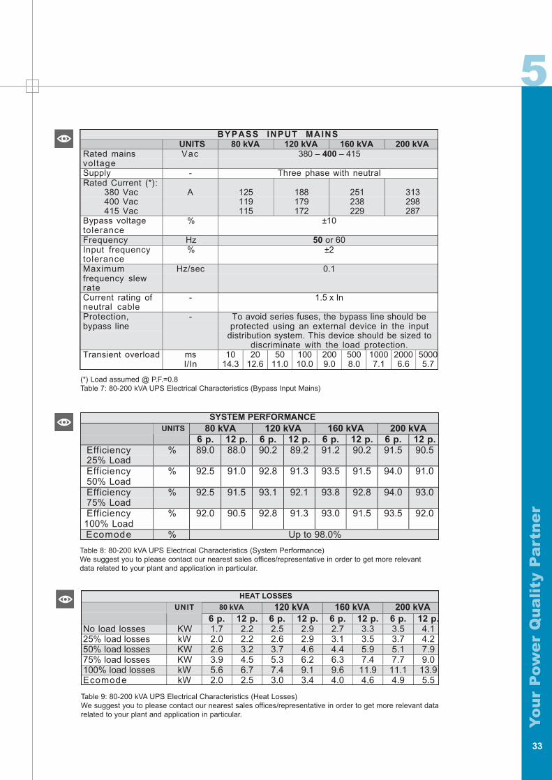
rTable 8: 80-200 kVA UPS Electrical Characteristics (System Performance) We suggest you to please contact our nearest sales offices/representative in order to get more relevantdata related to your plant and application in particular.
33
(*) Load assumed @ P.F.=0.8Table 7: 80-200 kVA UPS Electrical Characteristics (Bypass Input Mains)
Table 9: 80-200 kVA UPS Electrical Characteristics (Heat Losses)We suggest you to please contact our nearest sales offices/representative in order to get more relevant datarelated to your plant and application in particular.
BYPASS INPUT MAINSUNITS 80 kVA 120 kVA 160 kVA 200 kVA
Rated mainsvoltage
Vac 380 – 400 – 415
Supply - Three phase with neutralRated Current (*):
380 Vac400 Vac415 Vac
A 125119115
188179172
251238229
313298287
Bypass voltagetolerance
% ±10
Frequency Hz 50 or 60Input frequencytolerance
% ±2
Maximumfrequency slewrate
Hz/sec 0.1
Current rating ofneutral cable
- 1.5 x In
Protection,bypass line
- To avoid series fuses, the bypass line should beprotected using an external device in the input
distribution system. This device should be sized todiscriminate with the load protection.
Transient overload msI/In
1014.3
2012.6
5011.0
10010.0
2009.0
5008.0
10007.1
20006.6
50005.7
SYSTEM PERFORMANCE80 kVA 120 kVA 160 kVA 200 kVAUNITS
6 p. 12 p. 6 p. 12 p. 6 p. 12 p. 6 p. 12 p.Efficiency25% Load
% 89.0 88.0 90.2 89.2 91.2 90.2 91.5 90.5
Efficiency50% Load
% 92.5 91.0 92.8 91.3 93.5 91.5 94.0 91.0
Efficiency75% Load
% 92.5 91.5 93.1 92.1 93.8 92.8 94.0 93.0
Efficiency100% Load
% 92.0 90.5 92.8 91.3 93.0 91.5 93.5 92.0
Ecomode % Up to 98.0%
HEAT LOSSES
80 kVA 120 kVA 160 kVA 200 kVAUNIT
6 p. 12 p. 6 p. 12 p. 6 p. 12 p. 6 p. 12 p.No load losses KW 1.7 2.2 2.5 2.9 2.7 3.3 3.5 4.125% load losses kW 2.0 2.2 2.6 2.9 3.1 3.5 3.7 4.250% load losses KW 2.6 3.2 3.7 4.6 4.4 5.9 5.1 7.975% load losses KW 3.9 4.5 5.3 6.2 6.3 7.4 7.7 9.0100% load losses kW 5.6 6.7 7.4 9.1 9.6 11.9 11.1 13.9Ecomode kW 2.0 2.5 3.0 3.4 4.0 4.6 4.9 5.5
5
Yo
ur
Pow
er
Qu
ali
ty P
art
ne
r
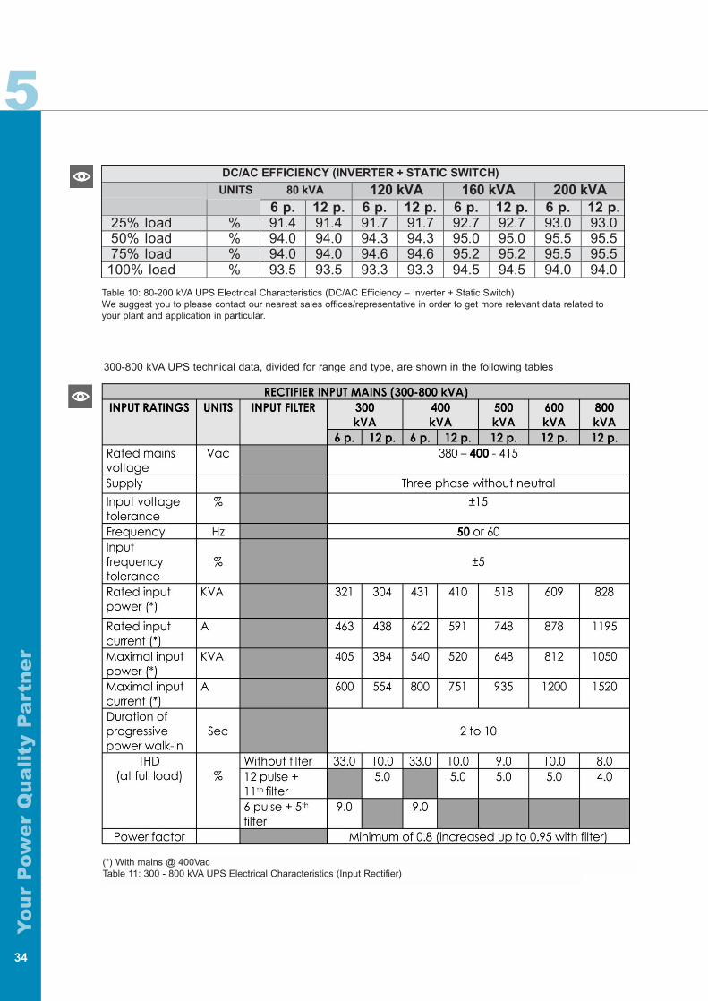
300-800 kVA UPS technical data, divided for range and type, are shown in the following tables
34
Table 10: 80-200 kVA UPS Electrical Characteristics (DC/AC Efficiency – Inverter + Static Switch)We suggest you to please contact our nearest sales offices/representative in order to get more relevant data related toyour plant and application in particular.
DC/AC EFFICIENCY (INVERTER + STATIC SWITCH)
80 kVA 120 kVA 160 kVA 200 kVAUNITS
6 p. 12 p. 6 p. 12 p. 6 p. 12 p. 6 p. 12 p.25% load % 91.4 91.4 91.7 91.7 92.7 92.7 93.0 93.050% load % 94.0 94.0 94.3 94.3 95.0 95.0 95.5 95.575% load % 94.0 94.0 94.6 94.6 95.2 95.2 95.5 95.5
100% load % 93.5 93.5 93.3 93.3 94.5 94.5 94.0 94.0
(*) With mains @ 400VacTable 11: 300 - 800 kVA UPS Electrical Characteristics (Input Rectifier)
5
Yo
ur
Pow
er
Qu
ali
ty P
art
ne
r
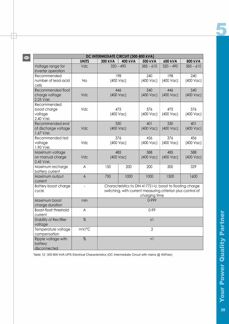
Table 12: 300-800 kVA UPS Electrical Characteristics (DC Intermediate Circuit with mains @ 400Vac)
35
5
Yo
ur
Pow
er
Qu
ali
ty P
art
ne
r
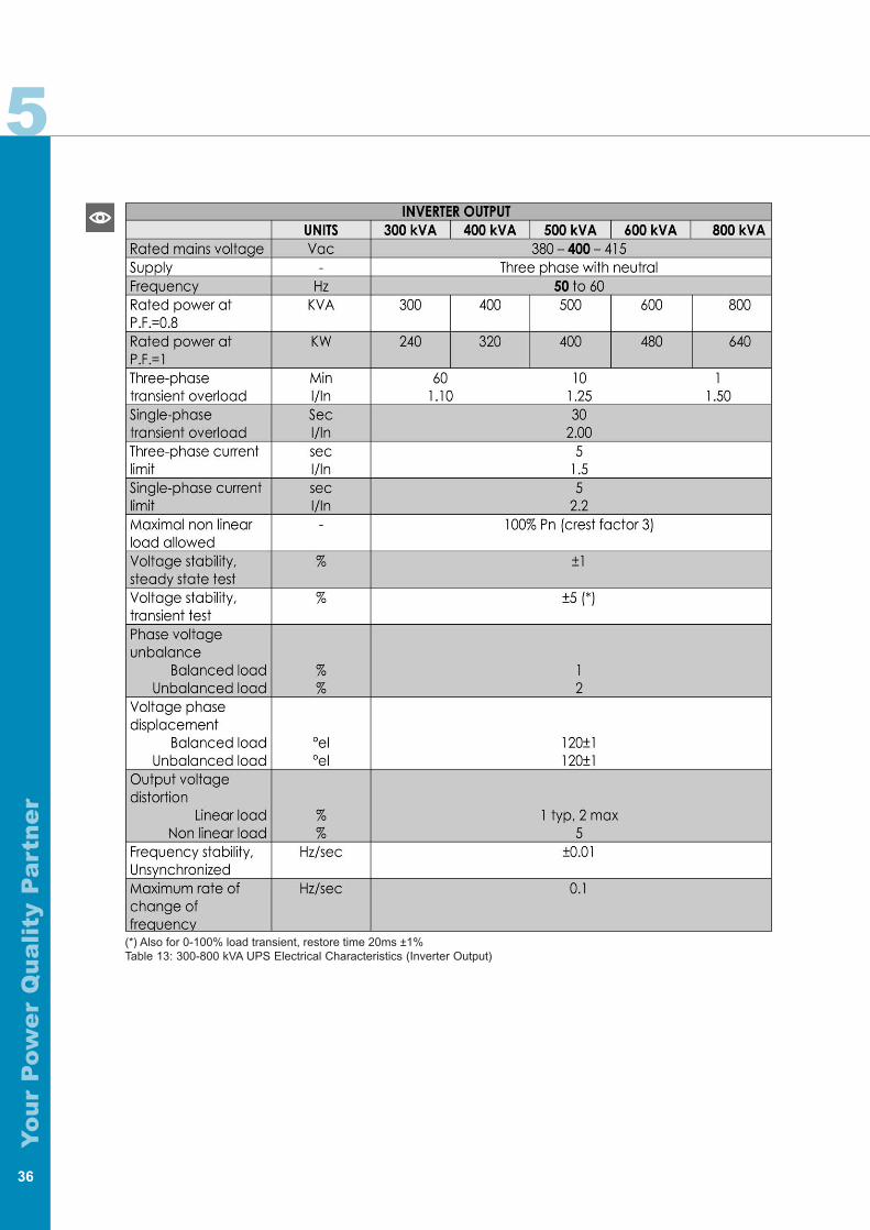
(*) Also for 0-100% load transient, restore time 20ms ±1% Table 13: 300-800 kVA UPS Electrical Characteristics (Inverter Output)
36
5
Yo
ur
Pow
er
Qu
ali
ty P
art
ne
r
37
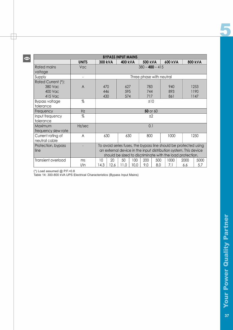
(*) Load assumed @ P.F.=0.8Table 14: 300-800 kVA UPS Electrical Characteristics (Bypass Input Mains)
5
Yo
ur
Pow
er
Qu
ali
ty P
art
ne
r
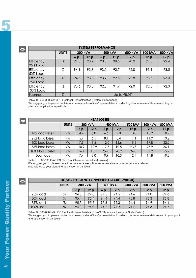
Table 15: 300-800 kVA UPS Electrical Characteristics (System Performance)We suggest you to please contact our nearest sales offices/representative in order to get more relevant data related to yourplant and application in particular.
38
Table 16: 300-800 kVA UPS Electrical Characteristics (Heat Losses)We suggest you to please contact our nearest sales offices/representative in order to get more relevantdata related to your plant and application in particular.
Table 17: 300-800 kVA UPS Electrical Characteristics (DC/AC Efficiency – Inverter + Static Switch)We suggest you to please contact our nearest sales offices/representative in order to get more relevant data related to your plantand application in particular.
5
Yo
ur
Pow
er
Qu
ali
ty P
art
ne
r
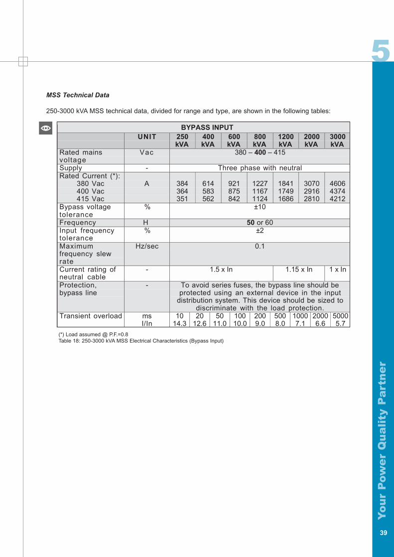
MSS Technical Data
250-3000 kVA MSS technical data, divided for range and type, are shown in the following tables:
39
(*) Load assumed @ P.F.=0.8Table 18: 250-3000 kVA MSS Electrical Characteristics (Bypass Input)
BYPASS INPUTUNIT 250
kVA400kVA
600kVA
800kVA
1200kVA
2000kVA
3000kVA
Rated mainsvoltage
Vac 380 – 400 – 415
Supply - Three phase with neutralRated Current (*):
380 Vac400 Vac415 Vac
A 384364351
614583562
921875842
122711671124
184117491686
307029162810
460643744212
Bypass voltagetolerance
% ±10
Frequency H 50 or 60Input frequencytolerance
% ±2
Maximumfrequency slewrate
Hz/sec 0.1
Current rating ofneutral cable
- 1.5 x In 1.15 x In 1 x In
Protection,bypass line
- To avoid series fuses, the bypass line should beprotected using an external device in the input
distribution system. This device should be sized todiscriminate with the load protection.
Transient overload msI/In
1014.3
2012.6
5011.0
10010.0
2009.0
5008.0
10007.1
20006.6
50005.7

Yo
ur
Pow
er
Qu
ali
ty P
art
ne
r
40
6 6
Yo
ur
Pow
er
Qu
ali
ty P
art
ne
r
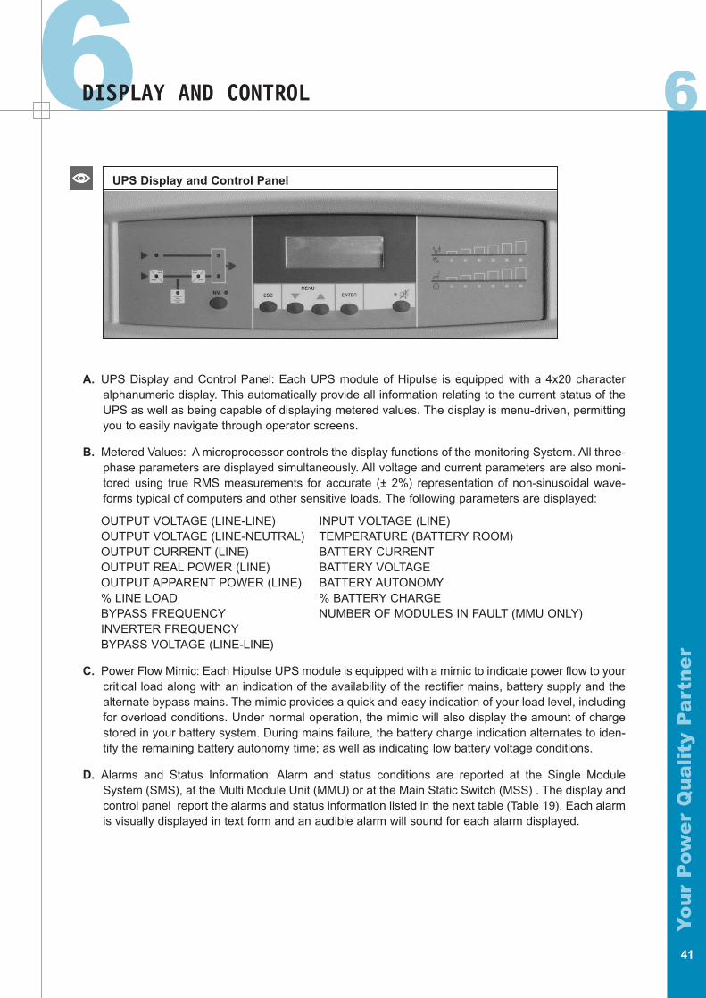
DISPLAY AND CONTROL
A. UPS Display and Control Panel: Each UPS module of Hipulse is equipped with a 4x20 characteralphanumeric display. This automatically provide all information relating to the current status of theUPS as well as being capable of displaying metered values. The display is menu-driven, permittingyou to easily navigate through operator screens.
B. Metered Values: A microprocessor controls the display functions of the monitoring System. All three-phase parameters are displayed simultaneously. All voltage and current parameters are also moni-tored using true RMS measurements for accurate (± 2%) representation of non-sinusoidal wave-forms typical of computers and other sensitive loads. The following parameters are displayed:
OUTPUT VOLTAGE (LINE-LINE) INPUT VOLTAGE (LINE)OUTPUT VOLTAGE (LINE-NEUTRAL) TEMPERATURE (BATTERY ROOM)OUTPUT CURRENT (LINE) BATTERY CURRENTOUTPUT REAL POWER (LINE) BATTERY VOLTAGEOUTPUT APPARENT POWER (LINE) BATTERY AUTONOMY% LINE LOAD % BATTERY CHARGEBYPASS FREQUENCY NUMBER OF MODULES IN FAULT (MMU ONLY)INVERTER FREQUENCYBYPASS VOLTAGE (LINE-LINE)
C. Power Flow Mimic: Each Hipulse UPS module is equipped with a mimic to indicate power flow to yourcritical load along with an indication of the availability of the rectifier mains, battery supply and thealternate bypass mains. The mimic provides a quick and easy indication of your load level, includingfor overload conditions. Under normal operation, the mimic will also display the amount of chargestored in your battery system. During mains failure, the battery charge indication alternates to iden-tify the remaining battery autonomy time; as well as indicating low battery voltage conditions.
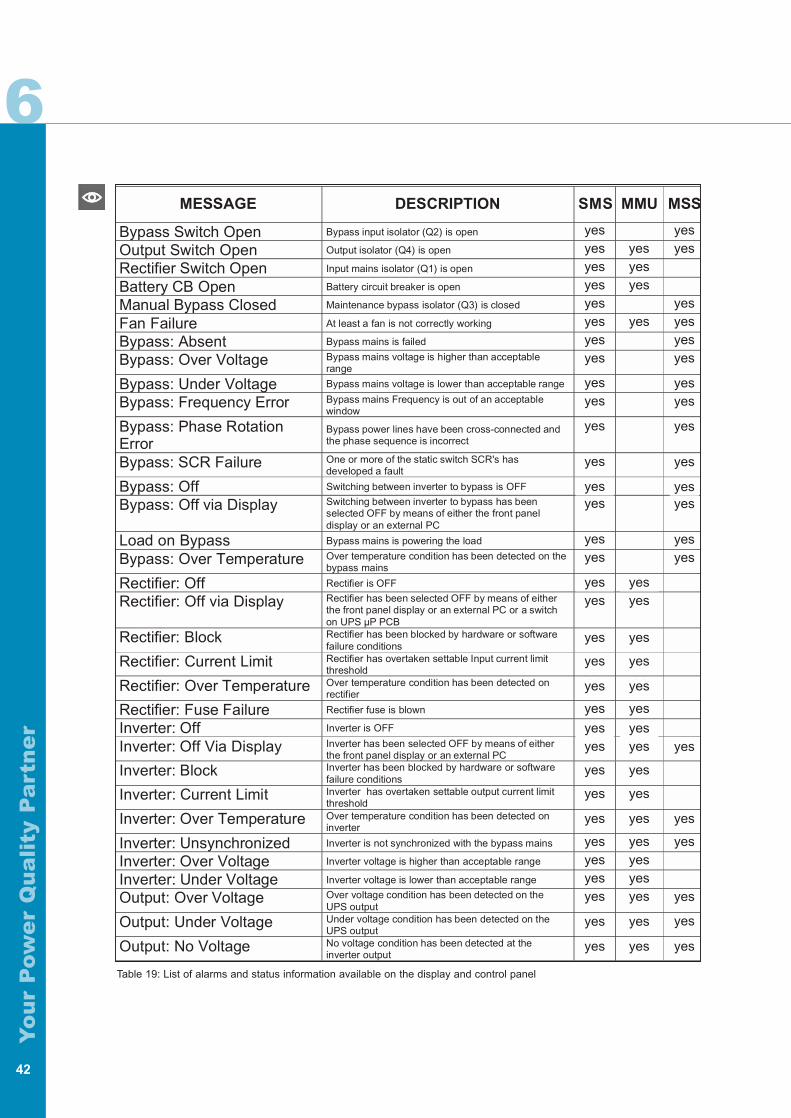
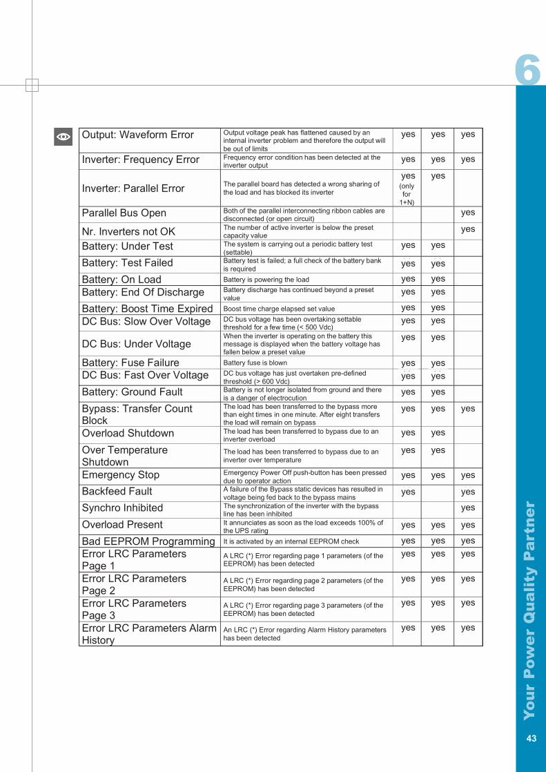
D. Alarms and Status Information: Alarm and status conditions are reported at the Single ModuleSystem (SMS), at the Multi Module Unit (MMU) or at the Main Static Switch (MSS) . The display andcontrol panel report the alarms and status information listed in the next table (Table 19). Each alarmis visually displayed in text form and an audible alarm will sound for each alarm displayed.
41
UPS Display and Control Panel
6
Yo
ur
Pow
er
Qu
ali
ty P
art
ne
r
Table 19: List of alarms and status information available on the display and control panel
42
MESSAGE DESCRIPTION SMS MMU MSS
Bypass Switch Open Bypass input isolator (Q2) is open X XOutput Switch Open Output isolator (Q4) is open X X XRectifier Switch Open Input mains isolator (Q1) is open X XBattery CB Open Battery circuit breaker is open X XManual Bypass Closed Maintenance bypass isolator (Q3) is closed X XFan Failure At least a fan is not correctly working X X XBypass: Absent Bypass mains is failed X XBypass: Over Voltage Bypass mains voltage is higher than acceptable
rangeX X
Bypass: Under Voltage Bypass mains voltage is lower than acceptable range X XBypass: Frequency Error Bypass mains Frequency is out of an acceptable
windowX X
Bypass: Phase RotationError
Bypass power lines have been cross-connected andthe phase sequence is incorrect
X X
Bypass: SCR Failure One or more of the static switch SCR's hasdeveloped a fault
X X
Bypass: Off Switching between inverter to bypass is OFF X XBypass: Off via Display Switching between inverter to bypass has been
selected OFF by means of either the front paneldisplay or an external PC
X X
Load on Bypass Bypass mains is powering the load X XBypass: Over Temperature Over temperature condition has been detected on the
bypass mainsX X
Rectifier: Off Rectifier is OFF X XRectifier: Off via Display Rectifier has been selected OFF by means of either
the front panel display or an external PC or a switchon UPS µP PCB
X X
Rectifier: Block Rectifier has been blocked by hardware or softwarefailure conditions
X X
Rectifier: Current Limit Rectifier has overtaken settable Input current limitthreshold
X X
Rectifier: Over Temperature Over temperature condition has been detected onrectifier
X X
Rectifier: Fuse Failure Rectifier fuse is blown X XInverter: Off Inverter is OFF X XInverter: Off Via Display Inverter has been selected OFF by means of either
the front panel display or an external PCX X X
Inverter: Block Inverter has been blocked by hardware or softwarefailure conditions
X X
Inverter: Current Limit Inverter has overtaken settable output current limitthreshold
X X
Inverter: Over Temperature Over temperature condition has been detected oninverter
X X X
Inverter: Unsynchronized Inverter is not synchronized with the bypass mains X X XInverter: Over Voltage Inverter voltage is higher than acceptable range X XInverter: Under Voltage Inverter voltage is lower than acceptable range X XOutput: Over Voltage Over voltage condition has been detected on the
UPS outputX X X
Output: Under Voltage Under voltage condition has been detected on theUPS output
X X X
Output: No Voltage No voltage condition has been detected at theinverter output
X X X
yesyes yesyes yesyes yesyesyes yesyesyes
yesyes
yes
yes
yesyes
yesyes
yes yesyes yes
yes yes
yes yes
yes yes
yes yes
yes yesyes yes
yes yes
yes yes
yes yes
yes yesyes yesyes yesyes yes
yes yes
yes yes
yesyes
yesyesyesyes
yesyes
yes
yes
yesyes
yesyes
yes
yes
yes
yes
yes
yes
6
Yo
ur
Pow
er
Qu
ali
ty P
art
ne
r
43
Output: Waveform Error Output voltage peak has flattened caused by aninternal inverter problem and therefore the output willbe out of limits
X X X
Inverter: Frequency Error Frequency error condition has been detected at theinverter output
X X X
Inverter: Parallel Error The parallel board has detected a wrong sharing ofthe load and has blocked its inverter
X(onlyfor
1+N)
X
Parallel Bus Open Both of the parallel interconnecting ribbon cables aredisconnected (or open circuit)
X
Nr. Inverters not OK The number of active inverter is below the presetcapacity value
X
Battery: Under Test The system is carrying out a periodic battery test(settable)
X X
Battery: Test Failed Battery test is failed; a full check of the battery bankis required
X X
Battery: On Load Battery is powering the load X XBattery: End Of Discharge Battery discharge has continued beyond a preset
valueX X
Battery: Boost Time Expired Boost time charge elapsed set value X XDC Bus: Slow Over Voltage DC bus voltage has been overtaking settable
threshold for a few time (< 500 Vdc)X X
DC Bus: Under VoltageWhen the inverter is operating on the battery thismessage is displayed when the battery voltage hasfallen below a preset value
X X
Battery: Fuse Failure Battery fuse is blown X XDC Bus: Fast Over Voltage DC bus voltage has just overtaken pre-defined
threshold (> 600 Vdc)X X
Battery: Ground Fault Battery is not longer isolated from ground and thereis a danger of electrocution
X X
Bypass: Transfer CountBlock
The load has been transferred to the bypass morethan eight times in one minute. After eight transfersthe load will remain on bypass
X X X
Overload Shutdown The load has been transferred to bypass due to aninverter overload
X X
Over TemperatureShutdown
The load has been transferred to bypass due to aninverter over temperature
X X
Emergency Stop Emergency Power Off push-button has been presseddue to operator action
X X X
Backfeed Fault A failure of the Bypass static devices has resulted involtage being fed back to the bypass mains
X X
Synchro Inhibited The synchronization of the inverter with the bypassline has been inhibited
X
Overload Present It annunciates as soon as the load exceeds 100% ofthe UPS rating
X X X
Bad EEPROM Programming It is activated by an internal EEPROM check X X XError LRC ParametersPage 1
A LRC (*) Error regarding page 1 parameters (of theEEPROM) has been detected
X X X
Error LRC ParametersPage 2
A LRC (*) Error regarding page 2 parameters (of theEEPROM) has been detected
X X X
Error LRC ParametersPage 3
A LRC (*) Error regarding page 3 parameters (of theEEPROM) has been detected
X X X
Error LRC Parameters AlarmHistory
An LRC (*) Error regarding Alarm History parametershas been detected
X X X
yes yes yes
yes yes yes
yes
yes
yes
yes
yes yes
yes yes
yes yes
yes yes
yes yes
yes yes
yes yes
yes yes
yes yes
yes yes
yes yes
yes yes
yes yes
yes yes
yes
yes
yes
yes
yes
yesyes yes
yesyes yes
yesyes yes
yesyes yes
yesyes yes
yesyes yes
6
Yo
ur
Pow
er
Qu
ali
ty P
art
ne
r
44
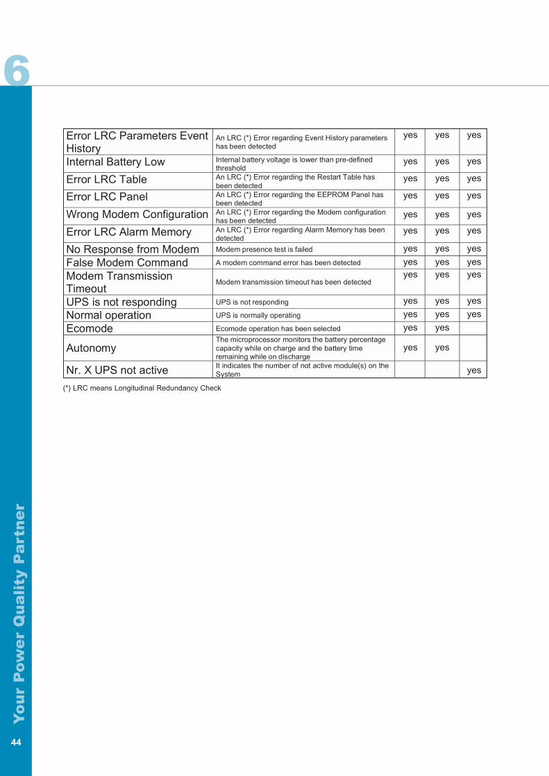
Error LRC Parameters EventHistory
An LRC (*) Error regarding Event History parametershas been detected
X X X
Internal Battery Low Internal battery voltage is lower than pre-definedthreshold
X X X
Error LRC Table An LRC (*) Error regarding the Restart Table hasbeen detected
X X X
Error LRC Panel An LRC (*) Error regarding the EEPROM Panel hasbeen detected
X X X
Wrong Modem Configuration An LRC (*) Error regarding the Modem configurationhas been detected
X X X
Error LRC Alarm Memory An LRC (*) Error regarding Alarm Memory has beendetected
X X X
No Response from Modem Modem presence test is failed X X XFalse Modem Command A modem command error has been detected X X XModem TransmissionTimeout
Modem transmission timeout has been detectedX X X
UPS is not responding UPS is not responding X X XNormal operation UPS is normally operating X x xEcomode Ecomode operation has been selected X X
AutonomyThe microprocessor monitors the battery percentagecapacity while on charge and the battery timeremaining while on discharge
X X
Nr. X UPS not active It indicates the number of not active module(s) on theSystem x
(*) LRC means Longitudinal Redundancy Check
yes yes yes
yes yes yes
yes yes yes
yes yes yes
yes yes yes
yes yes yes
yes yes yes
yes yes yesyes yes yes
yes yes yes
yes yes yes
yes
yes yes
yes yes
7 7
Yo
ur
Pow
er
Qu
ali
ty P
art
ne
r
OPTIONAL SOLUTION
45
To further improve the quality of your power quality solution, Hipulse units can be coupled with severaloptional components. Some of these will enhance your control of the system, some will make the instal-lation easier, while some other will increase the level of protection of your applications. All can significantly add to a Hipulse system and suit your needs of a complete Power Quality Solution.The benefits and applications of each will be clarified in the following paragraphs, however, you can con-fidently refer to any Liebert or Liebert Hiross representative should you need further explanation abouteach of the following solutions. Optional components fall broadly under three categories:• communications solutions• power reliability solutions• additional componentsBelow is a brief description of all of them.
COMMUNICATIONS SOLUTIONS
Monitoring And Shutdown Software
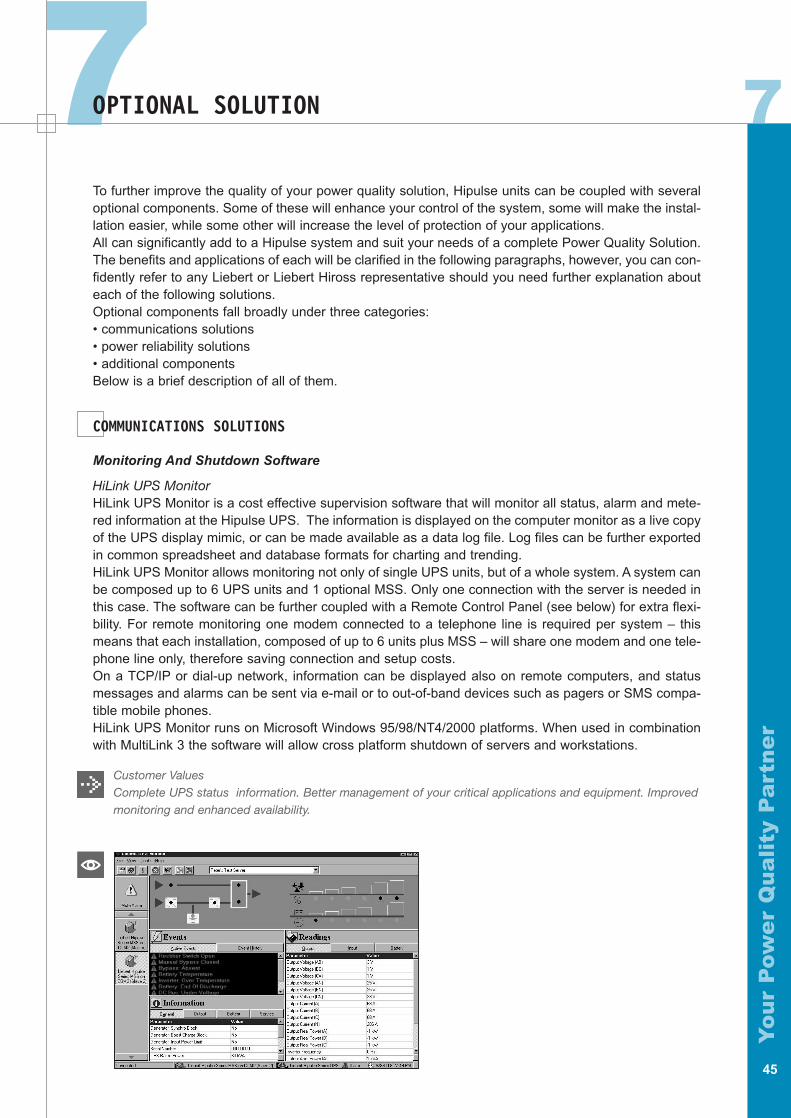
HiLink UPS MonitorHiLink UPS Monitor is a cost effective supervision software that will monitor all status, alarm and mete-red information at the Hipulse UPS. The information is displayed on the computer monitor as a live copyof the UPS display mimic, or can be made available as a data log file. Log files can be further exportedin common spreadsheet and database formats for charting and trending. HiLink UPS Monitor allows monitoring not only of single UPS units, but of a whole system. A system canbe composed up to 6 UPS units and 1 optional MSS. Only one connection with the server is needed inthis case. The software can be further coupled with a Remote Control Panel (see below) for extra flexi-bility. For remote monitoring one modem connected to a telephone line is required per system – thismeans that each installation, composed of up to 6 units plus MSS – will share one modem and one tele-phone line only, therefore saving connection and setup costs.On a TCP/IP or dial-up network, information can be displayed also on remote computers, and statusmessages and alarms can be sent via e-mail or to out-of-band devices such as pagers or SMS compa-tible mobile phones.HiLink UPS Monitor runs on Microsoft Windows 95/98/NT4/2000 platforms. When used in combinationwith MultiLink 3 the software will allow cross platform shutdown of servers and workstations.
Customer ValuesComplete UPS status information. Better management of your critical applications and equipment. Improvedmonitoring and enhanced availability.
7
Yo
ur
Pow
er
Qu
ali
ty P
art
ne
r
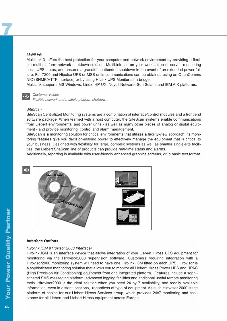
MultiLinkMultiLink 3 offers the best protection for your computer and network environment by providing a flexi-ble multi-platform network shutdown solution. MultiLink sits on your workstation or server, monitoringbasic UPS status, and ensures a graceful unattended shutdown in the event of an extended power fai-lure. For 7200 and Hipulse UPS or MSS units communications can be obtained using an OpenCommsNIC (SNMP/HTTP interface) or by using HiLink UPS Monitor as a bridge.MultiLink supports MS Windows, Linux, HP-UX, Novell Netware, Sun Solaris and IBM AIX platforms.
Customer ValuesFlexible network and multiple platform shutdown.
SiteScanSiteScan Centralized Monitoring systems are a combination of interface/control modules and a front endsoftware package. When teamed with a host computer, the SiteScan systems enable communicationsfrom Liebert environmental and power units - as well as many other pieces of analog or digital equip-ment - and provide monitoring, control and alarm management.SiteScan is a monitoring solution for critical environments that utilizes a facility-view approach: its moni-toring features give you decision-making power to effectively manage the equipment that is critical toyour business. Designed with flexibility for large, complex systems as well as smaller single-site facili-ties, the Liebert SiteScan line of products can provide real-time status and alarms.Additionally, reporting is available with user-friendly enhanced graphics screens, or in basic text format.
46
Interface Options
Hirolink IGM (Hirovisor 2000 Interface)Hirolink IGM is an interface device that allows integration of your Liebert Hiross UPS equipment formonitoring via the Hirovisor2000 supervision software. Customers requiring integration with aHirovisor2000 monitoring system will need to have one Hirolink IGM fitted on each UPS. Hirovisor isa sophisticated monitoring solution that allows you to monitor all Liebert Hiross Power UPS and HPAC(High Precision Air Conditioning) equipment from one integrated platform. Features include a sophi-sticated SMS messaging platform, advanced logging facilities and additional useful remote monitoringtools. Hirovisor2000 is the ideal solution when you need 24 by 7 availability, and readily availableinformation, even in distant locations, regardless of type of equipment. As such Hirovisor 2000 is theplatform of choice for our Liebert Hiross Services group, which provides 24x7 monitoring and assi-stance for all Liebert and Liebert Hiross equipment across Europe.
7
Yo
ur
Pow
er
Qu
ali
ty P
art
ne
r
Customer ValuesIntegration and control monitoring together with all Liebert Hiross HPAC and UPS equipment. EnhancedAvailability and Reduced Cost of Maintenance.
OpenComms NIC (SNMP/HTTP Interface)The OpenComms Network Interface Card provides status monitoring and alarm information throughSNMPv1 protocol messages. This option allows connection over a 10-baseT Ethernet network.Additionally, it will also transmit the same status information and all measured parameters for display toa web browser via the HTTP protocol. The information is visible on common browsers like InternetExplorer 4.0 or better, Netscape Navigator 4.0 or better, and Opera 5.0 or better.
Customer ValuesPopular Internet standard protocol. Web enabled monitoring. NMS integration, ideal in networking environ-ments and Information Technology companies.
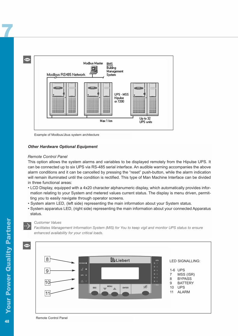
Modbus/Jbus Option (BMS Interface)The Modbus/Jbus Option can be installed on Hipulse units by replacing a programmable component onthe UPS Logic Board. This option allows communication between UPS (or MSS) and any BuildingManagement System, by using the standard Modbus/Jbus RTU protocol.Building Management Systems are sophisticated programs that help facility managers and techniciansmonitor and control temperature and ventilation conditions, security and fire safety, power distributionsystems as well as power supply systems - like UPS units - in non-residential buildings.
Customer ValuesWorks with most common Building Management System. Simple and time-tested solution.
47
7
Yo
ur
Pow
er
Qu
ali
ty P
art
ne
r
48
Other Hardware Optional Equipment
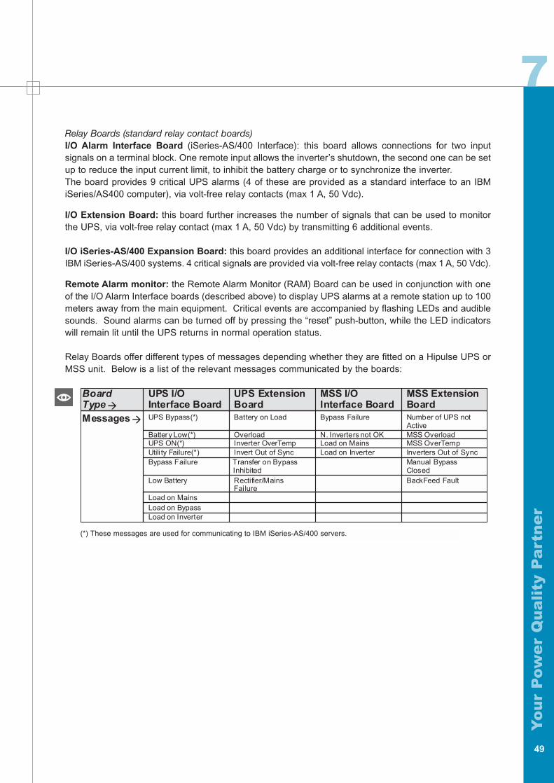
Remote Control PanelThis option allows the system alarms and variables to be displayed remotely from the Hipulse UPS. Itcan be connected up to six UPS via RS-485 serial interface. An audible warning accompanies the abovealarm conditions and it can be cancelled by pressing the “reset” push-button, while the alarm indicationwill remain illuminated until the condition is rectified. This type of Man Machine Interface can be dividedin three functional areas:• LCD Display, equipped with a 4x20 character alphanumeric display, which automatically provides infor-
mation relating to your System and metered values current status. The display is menu driven, permit-ting you to easily navigate through operator screens.
• System alarm LED, (left side) representing the main information about your System status.• System apparatus LED, (right side) representing the main information about your connected Apparatus
status.
Customer ValuesFacilitates Management Information System (MIS) for You to keep vigil and monitor UPS status to ensureenhanced availability for your critical loads.
LED SIGNALLING:
1-6 UPS7 MSS (ISR)8 BYPASS9 BATTERY10 UPS11 ALARM
8
9
10
11
Example of Modbus/Jbus system architecture
Remote Control Panel
7
Yo
ur
Pow
er
Qu
ali
ty P
art
ne
r
Relay Boards (standard relay contact boards)I/O Alarm Interface Board (iSeries-AS/400 Interface): this board allows connections for two inputsignals on a terminal block. One remote input allows the inverter’s shutdown, the second one can be setup to reduce the input current limit, to inhibit the battery charge or to synchronize the inverter. The board provides 9 critical UPS alarms (4 of these are provided as a standard interface to an IBMiSeries/AS400 computer), via volt-free relay contacts (max 1 A, 50 Vdc).
I/O Extension Board: this board further increases the number of signals that can be used to monitorthe UPS, via volt-free relay contact (max 1 A, 50 Vdc) by transmitting 6 additional events.
I/O iSeries-AS/400 Expansion Board: this board provides an additional interface for connection with 3IBM iSeries-AS/400 systems. 4 critical signals are provided via volt-free relay contacts (max 1 A, 50 Vdc).
Remote Alarm monitor: the Remote Alarm Monitor (RAM) Board can be used in conjunction with oneof the I/O Alarm Interface boards (described above) to display UPS alarms at a remote station up to 100meters away from the main equipment. Critical events are accompanied by flashing LEDs and audiblesounds. Sound alarms can be turned off by pressing the “reset” push-button, while the LED indicatorswill remain lit until the UPS returns in normal operation status.
Relay Boards offer different types of messages depending whether they are fitted on a Hipulse UPS orMSS unit. Below is a list of the relevant messages communicated by the boards:
49
(*) These messages are used for communicating to IBM iSeries-AS/400 servers.
BoardType�Messages�
UPS I/OInterface BoardUPS Bypass(*)
Battery Low(*)UPS ON(*)Utili ty Failure(*)Bypass Failure
Low Battery
Load on InverterLoad on BypassLoad on Mains
Rectifier/MainsFailure
InhibitedTransfer on BypassInvert Out of SyncInverter OverTempOverload
Battery on Load
Load on InverterLoad on MainsN. Inverters not OK
Bypass Failure
BackFeed Fault
Inverters Out of SyncMSS OverTempMSS OverloadActiveNumber of UPS not
ClosedManual Bypass
MSS ExtensionBoard
MI
SS I/Onterface BoardB
UPS Extensionoard
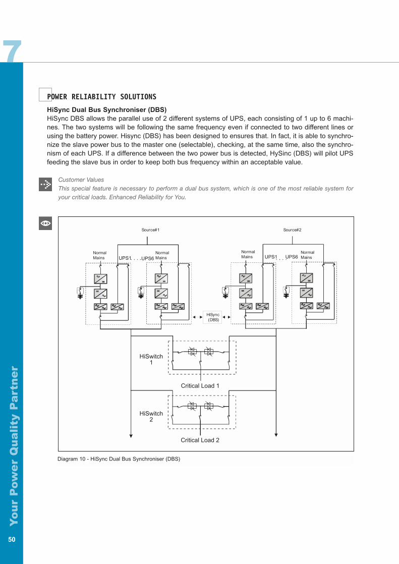
7
Yo
ur
Pow
er
Qu
ali
ty P
art
ne
r
50
NormalMains
Sour
NormalMains
NormalMains
NormalMains
HiSync(DBS)
Source#2Source#1
HiSwitch1
HiSwitch2
Critical Load 2
Critical Load 1
UPS1 UPS6UPS1 UPS6
Diagram 10 - HiSync Dual Bus Synchroniser (DBS)
POWER RELIABILITY SOLUTIONS
HiSync Dual Bus Synchroniser (DBS) HiSync DBS allows the parallel use of 2 different systems of UPS, each consisting of 1 up to 6 machi-nes. The two systems will be following the same frequency even if connected to two different lines orusing the battery power. Hisync (DBS) has been designed to ensures that. In fact, it is able to synchro-nize the slave power bus to the master one (selectable), checking, at the same time, also the synchro-nism of each UPS. If a difference between the two power bus is detected, HySinc (DBS) will pilot UPSfeeding the slave bus in order to keep both bus frequency within an acceptable value.
Customer ValuesThis special feature is necessary to perform a dual bus system, which is one of the most reliable system foryour critical loads. Enhanced Reliability for You.
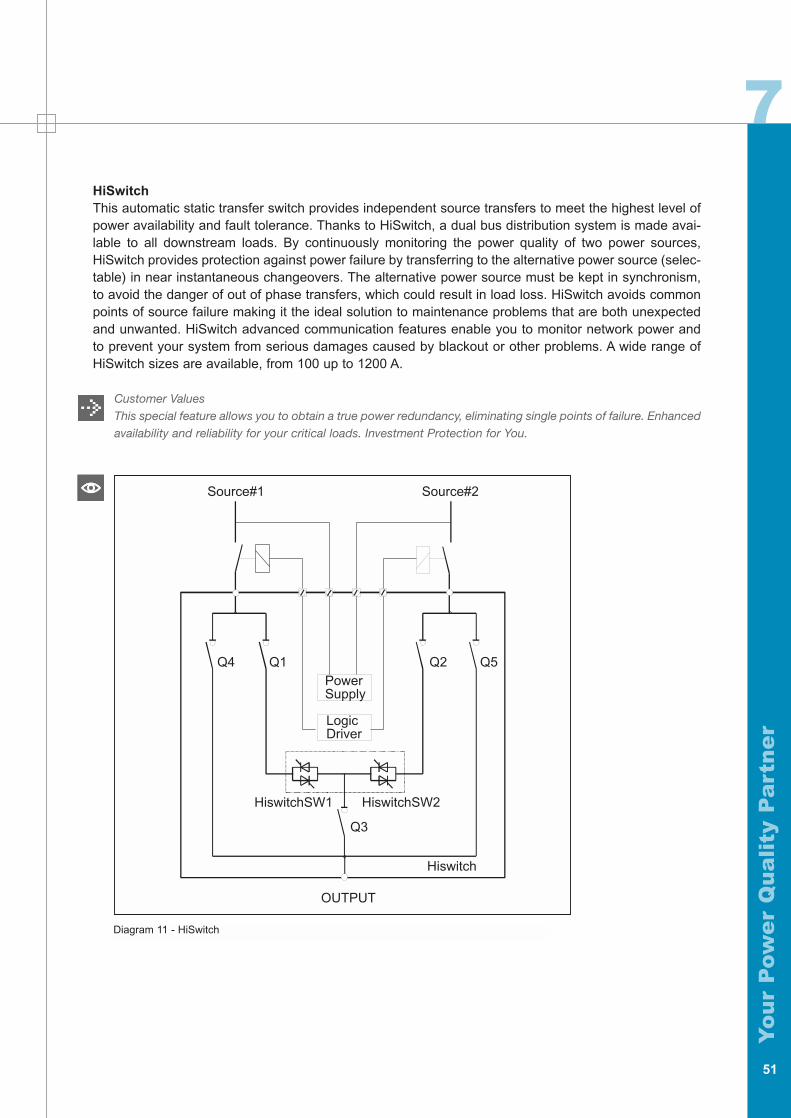
7
Yo
ur
Pow
er
Qu
ali
ty P
art
ne
r
HiSwitchThis automatic static transfer switch provides independent source transfers to meet the highest level ofpower availability and fault tolerance. Thanks to HiSwitch, a dual bus distribution system is made avai-lable to all downstream loads. By continuously monitoring the power quality of two power sources,HiSwitch provides protection against power failure by transferring to the alternative power source (selec-table) in near instantaneous changeovers. The alternative power source must be kept in synchronism,to avoid the danger of out of phase transfers, which could result in load loss. HiSwitch avoids commonpoints of source failure making it the ideal solution to maintenance problems that are both unexpectedand unwanted. HiSwitch advanced communication features enable you to monitor network power andto prevent your system from serious damages caused by blackout or other problems. A wide range ofHiSwitch sizes are available, from 100 up to 1200 A.
Customer ValuesThis special feature allows you to obtain a true power redundancy, eliminating single points of failure. Enhancedavailability and reliability for your critical loads. Investment Protection for You.
51
OUTPUT
Hiswitch
Q3
HiswitchSW2HiswitchSW1
LogicDriver
PowerSupply
Source#2Source#1
Q4 Q1 Q2 Q5
Diagram 11 - HiSwitch
7
Yo
ur
Pow
er
Qu
ali
ty P
art
ne
r
Input FilterProperly designed tuned filters are available to reduce the most critical harmonic pollution (5th and 11th).They also can improve the Hipulse input power factor, leading Power Factor (P.F.) from 0,8 up to 0,93.These input filters can be installed without any additional system footprint and their performances areshown in tables 4 & 11.
Input Isolation Transformer Input Isolation Transformers are required in case of having a galvanic isolation between Input/BypassMains and UPS Output. They are normally a Delta/ZigZag double wound transformer and they are avai-lable for every range of UPS (80-800 kVA). They are housed in an optional cabinet in which the non-automatic circuit breaker with fuses are also installed. Input isolation transformer are designed to powerboth rectifier and bypass mains, depending on their size.
Transient Voltage Surge Suppressor - TVSS This option is an advanced Transient Voltage Surge Suppressor. It has been designed for medium andheavy duty applications with capacities from 100 up to 400 kA per phase. TVSS is normally connectedat the bypass path of Hipulse or inside the HiSwitch as an optional item.
Customer ValuesInput Filter
Lower cost of ownership, due to lower electricity bill and reduced up-stream power pollution.Input Isolation Transformer
Enhanced optional protection:• Galvanic Isolation• Reduced Fault Current• Reduce the harmonic currents back on mains when the UPS is on bypass• Protection (optional) against Battery Ground Fault• Creation of Neutral
Top Cable Entry It is possible to have a top cable entry option when the power supply cables are coming from the top ofUPS. This kit incorporates a bus bar cabling system and flexible cables to connect to the Hipulseinput/output terminals. This option is available for a wide range of Hipulse UPS ratings.
Battery Circuit Breaker (BCB)Each Hipulse UPS module has the optional properly rated circuit breaker (500 Vdc) to isolate it from yourbattery. This breaker is to be housed in a separate enclosure, or mounted inside an optional batterycabinet. When the BCB is open, there will be no battery voltage inside the Hipulse enclosure. EachHipulse module will automatically be disconnected from your battery by opening its breaker when it rea-ches the minimum discharge voltage level or when signaled by other control functions.
1+N Parallel Interface KitThis kit allows UPS modules to operate in parallel mode, with SMS (Single Module System) without theuse of MSS (Main Static Switch).
Battery Ground Fault SensorThis option allows to detect a battery ground fault; it gives an alarm contact output that can be managedby your system.
52

7
Yo
ur
Pow
er
Qu
ali
ty P
art
ne
r
Battery Temperature SensorThis option allows the temperature compensated charging, in order to optimize on your battery lifetime.
Battery Control BoardThis option allows to control the Battery Circuit Breaker by piloting its trip coil.
Customer ValuesTop Cable Entry
This TCE may be used for both top and bottom cable entry, ease of installation, user flexibilityBattery Circuit Breaker
This feature offers extra protection to the battery, disconnecting it whenever conditions may require so. By avoiding that the battery works under inappropriate conditions, you will increase the battery life and yourequipment’s safety.The safety tools employed on Hipulse UPS are designed with no compromises regardingsafety and functionality. Investment protection for you, additional safety for your maintenance personnel.Battery Control Board
The battery control board is required when the BCB is fitted in the battery cabinets supplied by others.
Protection Degree (IP)This standard describes a system for classifying the degrees of protection provided by the enclosuresof the electrical equipment. Standard Hipulse enclosure is IP20, but it is possible to reach up to IP4xenclosure for most of the kVA ratings of Hipulse.
Customer ValuesThis feature allows Hipulse to operate in heavier environmental conditions. Enhanced availability.
53

Yo
ur
Pow
er
Qu
ali
ty P
art
ne
r
54
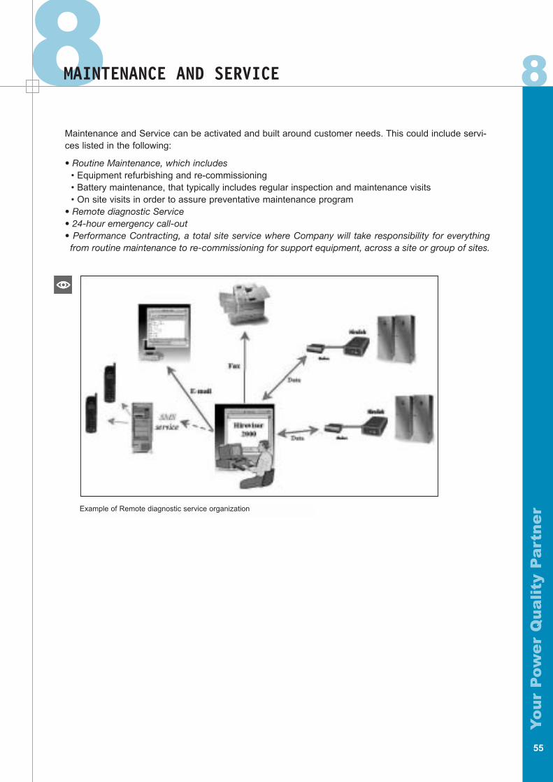
8 8
Yo
ur
Pow
er
Qu
ali
ty P
art
ne
r
MAINTENANCE AND SERVICE
Maintenance and Service can be activated and built around customer needs. This could include servi-ces listed in the following:
• Routine Maintenance, which includes• Equipment refurbishing and re-commissioning• Battery maintenance, that typically includes regular inspection and maintenance visits • On site visits in order to assure preventative maintenance program
• Remote diagnostic Service• 24-hour emergency call-out • Performance Contracting, a total site service where Company will take responsibility for everything
from routine maintenance to re-commissioning for support equipment, across a site or group of sites.
55
Example of Remote diagnostic service organization

Yo
ur
Pow
er
Qu
ali
ty P
art
ne
r
56
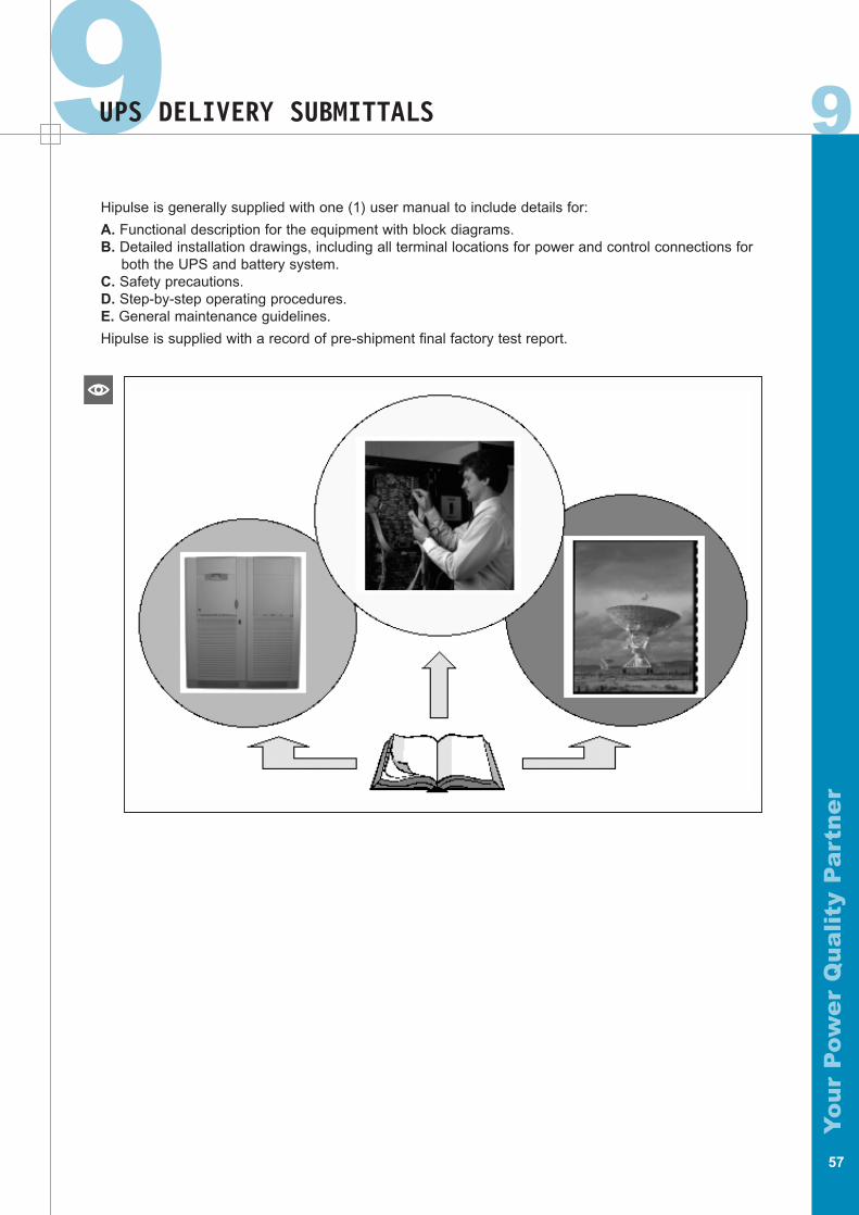
9 9
Yo
ur
Pow
er
Qu
ali
ty P
art
ne
r
UPS DELIVERY SUBMITTALS
Hipulse is generally supplied with one (1) user manual to include details for:
A. Functional description for the equipment with block diagrams.B. Detailed installation drawings, including all terminal locations for power and control connections for
both the UPS and battery system.C. Safety precautions.D. Step-by-step operating procedures.E. General maintenance guidelines.
Hipulse is supplied with a record of pre-shipment final factory test report.
57

Yo
ur
Pow
er
Qu
ali
ty P
art
ne
r
58
10 10
Yo
ur
Pow
er
Qu
ali
ty P
art
ne
r
QUALITY ASSURANCE
Manufacturer Qualifications
Hipulse is a product of a minimum of twenty years of reach experience and wealth of knowledge in thedesign, manufacture and testing of solid-state UPS system. Liebert Hiross is certified to ISO 9001.
Factory Testing
Before shipment, Hipulse is fully tested internally to ensure compliance with the specification.
59
11WARRANTYUPS Warranty
We warrant the unit against defects in workmanship for 12 months after initial start-up or 15 monthsafter ship date, whichever comes first.
Battery Warranty
The battery manufacturer’s standard warranty will generally be passed through to the end user.
11

Yo
ur
Pow
er
Qu
ali
ty P
art
ne
r
60
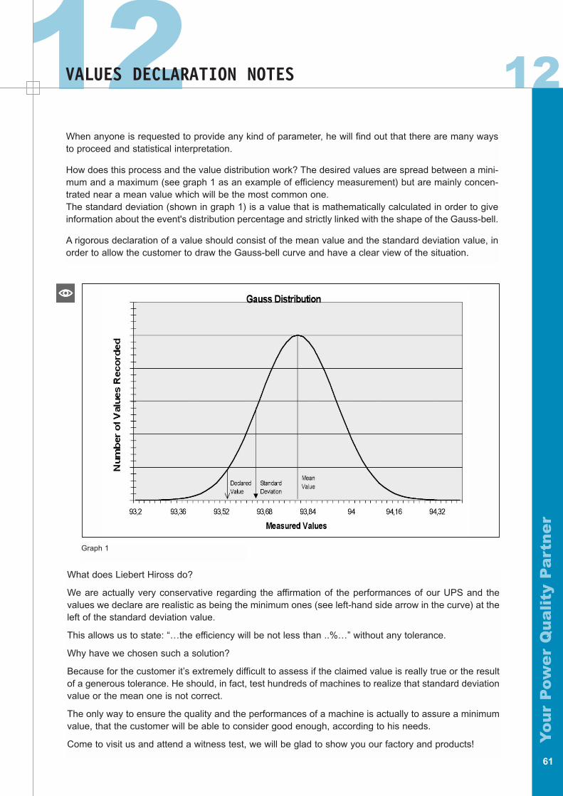
12 12
Yo
ur
Pow
er
Qu
ali
ty P
art
ne
r
VALUES DECLARATION NOTES
61
When anyone is requested to provide any kind of parameter, he will find out that there are many waysto proceed and statistical interpretation.
How does this process and the value distribution work? The desired values are spread between a mini-mum and a maximum (see graph 1 as an example of efficiency measurement) but are mainly concen-trated near a mean value which will be the most common one.The standard deviation (shown in graph 1) is a value that is mathematically calculated in order to giveinformation about the event's distribution percentage and strictly linked with the shape of the Gauss-bell.
A rigorous declaration of a value should consist of the mean value and the standard deviation value, inorder to allow the customer to draw the Gauss-bell curve and have a clear view of the situation.
What does Liebert Hiross do?
We are actually very conservative regarding the affirmation of the performances of our UPS and thevalues we declare are realistic as being the minimum ones (see left-hand side arrow in the curve) at theleft of the standard deviation value.
This allows us to state: “…the efficiency will be not less than ..%…” without any tolerance.
Why have we chosen such a solution?
Because for the customer it’s extremely difficult to assess if the claimed value is really true or the resultof a generous tolerance. He should, in fact, test hundreds of machines to realize that standard deviationvalue or the mean one is not correct.
The only way to ensure the quality and the performances of a machine is actually to assure a minimumvalue, that the customer will be able to consider good enough, according to his needs.
Come to visit us and attend a witness test, we will be glad to show you our factory and products!
Graph 1

Yo
ur
Pow
er
Qu
ali
ty P
art
ne
r
General Notes

Yo
ur
Pow
er
Qu
ali
ty P
art
ne
r
General Notes

Liebert HIROSS HeadquartersVia Leonardo da Vinci,8
35028 - Piove di Sacco (PD)-Italytel.+39 049 9719111 fax +39 049 5841257
www.liebert-hiross.com - [email protected]
High Performance Air ConditioningVia Leonardo da Vinci,8
35028 - Piove di Sacco (PD)tel.+39 049 9719111 fax +39 049 5841257
Power Quality SystemsVia Gioacchino Rossini,6
20098 - S.Giuliano Milanese (MI)tel.+39 02 98250 1 fax +39 02 98250273
Liebert HIROSS Services HeadquarterVia Leonardo da Vinci, 8
35028 - Piove di Sacco (PD) - Italytel. +39 049 9719111 fax +39 049 5841257
Liebert HIROSS contacts in the World
Liebert HIROSS AustriaHandelskai 102 -1200 Wien
tel.+43 1 33189221 fax +43 1 33189246
Liebert HIROSS BeneluxWatergoorweg 87 - 3861 MA Nijkerk
The Netherlandstel.+31 33 2474074 fax +31 33 2474075
Liebert HIROSS Czech RepublicNa Pricce 72/6 - 14200 Praha 4
tel.+42 02 4727954 fax +42 02 4718717
Liebert HIROSS EspañaAvda. Industria, 11
Polígono Industrial Alcobendas - 28108 Alcobendas (Madrid)tel.+34 902 100 494 fax +34 902 181 936
Liebert HIROSS France124 Avenue Gallieni - 93170 Bagnolet
tel.+33 1 43600177 fax +33 1 43602665
Liebert HIROSS GermanyLiebigstraße 9 - 85551 Kirchheim - München
tel.+49 89 9050070 fax +49 89 90500710
ENP HungaryEtele ut.68 - 1115 Budapest
tel.+36 1 203 0304 fax +36 1 203 0308
Liebert HIROSS ItalyVia Gioacchino Rossini,6
20098 - S.Giuliano Milanese - Milanotel.+39 02 982501 fax +39 02 9844633
Liebert HIROSS PolandUl.Konstruktorska,11A-02-673 Warszawatel.+48 22 5485260 fax +48 22 5485261
Liebert HIROSS RussiaMalaya Trubetskaya str.8
Korp.B,11th floor - 119881 Moscowtel.+7 095 2329473 fax +7 095 2320358
Liebert HIROSS SwitzerlandRaffelstraße 29 - 8045 Zürich
tel.+41 1456 5060 fax +41 1456 5070
Liebert HIROSS TurkeyEdin &Suner Plaza
Meydan Sokak 14 - Kat 2 -Akatlar - 80630 Istanbultel.+90 212 3511993 fax +90 212 3511994
Liebert HIROSS United KingdomGlobe Park - Marlow - Buckinghamshire - SL7 1YG
tel.+44 1628 403200 fax +44 1628 403298
Issued by Marketing Management Team - Milan
Document Reference: PQB04a (Version - 1.0)
PQ
B04
a/C
opis
tam
pa 0
1-03
/Pri
nted
in I
taly