Embed Size (px)
Citation preview

APPENDIX 8A HKLR – Construction & Demolition Materials Management Plan
Highways Department of HKSAR
Agreement No. CE 26/2003 (HY) Hong Kong Section of Hong Kong-Zhuhai-Macao Bridge and Connection with North Lantau Highway – Investigation (now renamed as HZMB Hong Kong Link Road)
Construction and Demolition Material Management Plan
Rpt Ref. 121-03
Agreement No. CE 26/2003 (HY) Hong Kong Section of Hong Kong-Zhuhai-Macao Bridge and Connection with North Lantau Highway – Investigation (now renamed as HZMB Hong Kong Link Road) Construction and Demolition Material Management Plan
24037-REP-121-03 Page i Ove Arup & Partners International Ltd
July 2009
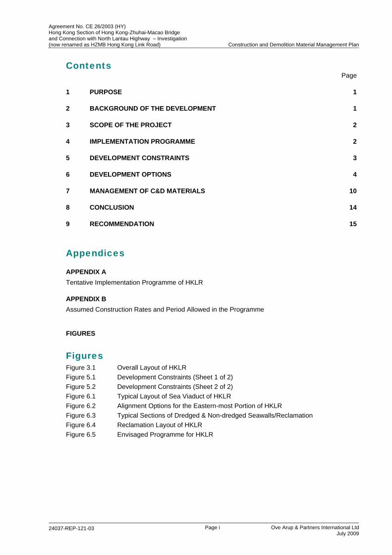
Contents Page
1 PURPOSE 1
2 BACKGROUND OF THE DEVELOPMENT 1
3 SCOPE OF THE PROJECT 2
4 IMPLEMENTATION PROGRAMME 2
5 DEVELOPMENT CONSTRAINTS 3
6 DEVELOPMENT OPTIONS 4
7 MANAGEMENT OF C&D MATERIALS 10
8 CONCLUSION 14
9 RECOMMENDATION 15
Appendices
APPENDIX A Tentative Implementation Programme of HKLR
APPENDIX B Assumed Construction Rates and Period Allowed in the Programme
FIGURES
Figures Figure 3.1 Overall Layout of HKLR Figure 5.1 Development Constraints (Sheet 1 of 2) Figure 5.2 Development Constraints (Sheet 2 of 2) Figure 6.1 Typical Layout of Sea Viaduct of HKLR Figure 6.2 Alignment Options for the Eastern-most Portion of HKLR Figure 6.3 Typical Sections of Dredged & Non-dredged Seawalls/Reclamation Figure 6.4 Reclamation Layout of HKLR Figure 6.5 Envisaged Programme for HKLR
Agreement No. CE 26/2003 (HY) Hong Kong Section of Hong Kong-Zhuhai-Macao Bridge and Connection with North Lantau Highway – Investigation (now renamed as HZMB Hong Kong Link Road) Construction and Demolition Material Management Plan
24037-REP-121-03 Page 1 Ove Arup & Partners International Ltd
July 2009
1 PURPOSE 1.1 In accordance with ETWB Technical Circular No. 33/2002, a Construction & Demolition
Materials Management Plan (C&DMMP) should be prepared and submitted to Public Fill Committee (PFC) for approval for projects classified as designated projects under Schedule 2 of the EIAO, which generate more than 50,000m³ of construction and demolition (C&D) materials including rock or that requiring import fill in excess of 50,000m³. Hong Kong Link Road is a designated project under the EIAO. In addition, it requires a total fill volume of more than 10 million m³ (bulk volume). Therefore, approval of C&DMMP by PFC is required.
1.2 The purpose of this C&DMMP is to introduce measures to minimize C&D materials generation and to maximize reusing the C&D materials generated within the project. The C&D materials are surplus materials arising from any land excavation or formation, civil/building construction, roadwork, building renovation or demolition activities. They comprise the materials of rocks, concrete, asphalt, rubbles, bricks, stones, timber and earth. As the marine deposit does not belong to the above materials, the proposed arrangement to deal with dredged marine deposit in this project will be submitted and agreed separately with the Marine Fill Committee. Therefore, the details of the dredge marine deposit are not covered in this C&DMMP.
2 BACKGROUND OF THE DEVELOPMENT 2.1 In the 8th Hong Kong-Zhuhai-Macao Bridge (HZMB) Advance Work Co-ordination Group
meeting on 28 February 2008, the government of HKSAR (HKSARG), Guangdong Province and Macao Special Administrative Region agreed to build their own boundary crossing facilities and link roads within their respective territories. As a result, HKSARG will need to provide a link road within Hong Kong territory connecting the HZMB Main Bridge and the Hong Kong Boundary Crossing Facilities (HKBCF). The link road within Hong Kong (hereafter referred to as the Hong Kong Link Road (HKLR)) will replace the former HZMB Hong Kong Section and North Lantau Highway Connection.
2.2 The Investigation Study of this Project commenced in March 2004 which formulated and assessed the alignment options for the following:
(i) The section of HZMB from HKSAR Boundary to its landing point at northwest Lantau, referred to as HZMB Hong Kong Section.
(ii) The proposed highway connecting (i) with the North Lantau Highway, referred to as North Lantau Highway Connection.
The Investigation Study, however, has been inactive since early 2006 due to the need to align with the developments on the implementation of HZMB including the HKBCF arrangement
2.3 In view of the latest development of HZMB and the new impetus to move the entire HZMB project ahead expeditiously, the Investigation Study was reactivated on 15 August 2008. As the major task of this investigation Study after reactivation, the alignment option has been reviewed and modified in accordance with the latest development of HZMB. The Investigation Study is on-going to work out the details to such an extent to enable the Project to proceed to detailed design and construction stages.
Agreement No. CE 26/2003 (HY) Hong Kong Section of Hong Kong-Zhuhai-Macao Bridge and Connection with North Lantau Highway – Investigation (now renamed as HZMB Hong Kong Link Road) Construction and Demolition Material Management Plan
24037-REP-121-03 Page 2 Ove Arup & Partners International Ltd
July 2009
3 SCOPE OF THE PROJECT 3.1 The proposed HKLR is a dual 3-lane carriageway connecting HZMB Main Bridge at the
HKSAR boundary to the HKBCF proposed to be located at the north-east waters of the Airport. The total length of HKLR is about 12 km.
3.2 The HKLR alignment will take the form of sea viaduct from HKSAR boundary to the landing point at San Shek Wan headland and then up to Scenic Hill after skirting along the southern seawall of Airport Island near the Airport Channel. For the portion of HKLR from Scenic Hill to HKBCF, a combination of tunnel and at-grade road has been developed after consolidating the residents’ views through the public engagement exercises conducted since September 2008.
3.3 The recommended alignment of HKLR is shown in Figure 3.1. The scope of HKLR project comprises, but not limited to the following:
(a) construction of a dual 3-lane carriageway in the forms of viaduct, tunnel and at-grade road between the HZMB Main Bridge at the HKSAR boundary and HKBCF. Each carriageway will consist of three traffic lanes together with a hard shoulder;
(b) reclamation to provide land of about 23 ha in which about 19 ha is for the tunnel/at-grade road in HKLR and the remaining 4 ha is provided for HKBCF to construct the connection road between HKBCF and airport;
(c) provision of ventilation and administration buildings and other tunnel portal facilities, traffic control and surveillance systems, power supply, street lighting, fire fighting system, street furniture, traffic aids (including sign gantries), ship impact protection system, drainage and other facilities associated with the carriageway; and
(d) associated civil, structural, building, electrical and mechanical, geotechnical, marine, environmental protection, landscaping works, drainage mitigation measures and meteorological equipment relocation/enhancement measures including the reprovisioning of a weather station, addition of wind sensors and upgrading of a wind profiler station.
4 IMPLEMENTATION PROGRAMME 4.1 Currently, it is targeted to commence the construction works of HKLR in Early 2011. The
completion date of HKLR will need to match the HZMB Main Bridge. The HZMB Main Bridge is now endeavoured to commence the construction works in 2009 and is expected to be completed by 2015. In order to tie in with the HZMB Main Bridge, HKLR needs to be completed in 2015 for the commissioning of HZMB. The tentative implementation programme of HKLR is shown in Appendix A.
4.2 Tentatively, it is proposed that the Project will be implemented under 3 contract packages:
Package 1 – Portion of HKLR from HKSAR boundary to San Shek Wan headland (i.e. the open-sea marine viaduct portion) exclude the TCSS works.
Package 2 – Portion of HKLR from San Shek Wan headland to Scenic Hill (i.e. the viaduct structures along/across the Airport Channel plus a small portion on land overpassing J/O Scenic Road/ Chek Lap Kok South Road) exclude the TCSS works.
Package 3 – Portion of HKLR from Scenic Hill to HKBCF (i.e. partly in the form of tunnel and partly in the form of at-grade road) and the TCSS works for the entire HKLR.
Agreement No. CE 26/2003 (HY) Hong Kong Section of Hong Kong-Zhuhai-Macao Bridge and Connection with North Lantau Highway – Investigation (now renamed as HZMB Hong Kong Link Road) Construction and Demolition Material Management Plan
24037-REP-121-03 Page 3 Ove Arup & Partners International Ltd
July 2009
The interface between the contract packages will be identified and included in the contract documents. In addition, it is important that a Works Area of sufficient area would be available for the use in each of Package 1 and Package 2 to facilitate the manufacturing of bridge components. If there is only one Works Area could be available, Packages 1 and 2 may need to be merged and this will be further reviewed.
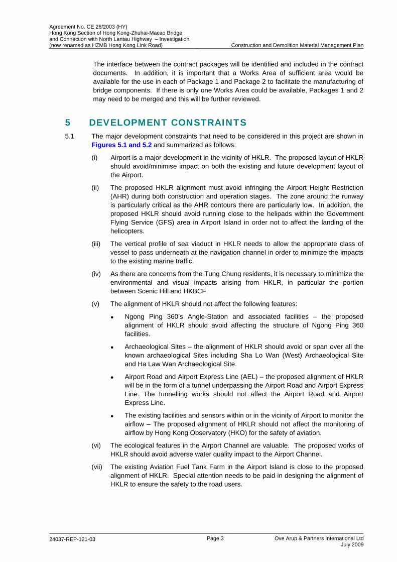
5 DEVELOPMENT CONSTRAINTS 5.1 The major development constraints that need to be considered in this project are shown in
Figures 5.1 and 5.2 and summarized as follows:
(i) Airport is a major development in the vicinity of HKLR. The proposed layout of HKLR should avoid/minimise impact on both the existing and future development layout of the Airport.
(ii) The proposed HKLR alignment must avoid infringing the Airport Height Restriction (AHR) during both construction and operation stages. The zone around the runway is particularly critical as the AHR contours there are particularly low. In addition, the proposed HKLR should avoid running close to the helipads within the Government Flying Service (GFS) area in Airport Island in order not to affect the landing of the helicopters.
(iii) The vertical profile of sea viaduct in HKLR needs to allow the appropriate class of vessel to pass underneath at the navigation channel in order to minimize the impacts to the existing marine traffic.
(iv) As there are concerns from the Tung Chung residents, it is necessary to minimize the environmental and visual impacts arising from HKLR, in particular the portion between Scenic Hill and HKBCF.
(v) The alignment of HKLR should not affect the following features:
Ngong Ping 360’s Angle-Station and associated facilities – the proposed alignment of HKLR should avoid affecting the structure of Ngong Ping 360 facilities.
Archaeological Sites – the alignment of HKLR should avoid or span over all the known archaeological Sites including Sha Lo Wan (West) Archaeological Site and Ha Law Wan Archaeological Site.
Airport Road and Airport Express Line (AEL) – the proposed alignment of HKLR will be in the form of a tunnel underpassing the Airport Road and Airport Express Line. The tunnelling works should not affect the Airport Road and Airport Express Line.
The existing facilities and sensors within or in the vicinity of Airport to monitor the airflow – The proposed alignment of HKLR should not affect the monitoring of airflow by Hong Kong Observatory (HKO) for the safety of aviation.
(vi) The ecological features in the Airport Channel are valuable. The proposed works of HKLR should avoid adverse water quality impact to the Airport Channel.
(vii) The existing Aviation Fuel Tank Farm in the Airport Island is close to the proposed alignment of HKLR. Special attention needs to be paid in designing the alignment of HKLR to ensure the safety to the road users.

Agreement No. CE 26/2003 (HY) Hong Kong Section of Hong Kong-Zhuhai-Macao Bridge and Connection with North Lantau Highway – Investigation (now renamed as HZMB Hong Kong Link Road) Construction and Demolition Material Management Plan
24037-REP-121-03 Page 4 Ove Arup & Partners International Ltd
July 2009
5.2 The measures to overcome the development constraints including the following:
(a) Close liaison with the Airport Authority Hong Kong on the interface issues between HKLR and the Airport to avoid/minimise the impact on both the existing and future development layout of the Airport.
(b) The vertical profile of HKLR will be designed to avoid infringing the AHR. Close liaison with the Civil Aviation Department, GFS and Airport Authority Hong Kong will be made to ensure that aviation safety will not be affect by the HKLR.
(c) To minimize the environmental and visual impacts, the portion of HKLR between Airport Island and HKBCF will take the form of at-grade road/ low-profile viaduct at the east coastline of Airport Island.
(d) In designing the alignment of HKLR, sufficient distance will be provided between HKLR and the adjacent existing/planned features. Close liaise will be made with relevant parties such as MTRCL, Antiquities and Monuments Office (AMO) and Hong Kong Observatory (HKO) to avoid affecting these features and the operation of the airflow monitoring facilities.
(e) The water quality impact arising from the proposed works of HKLR will be assessed in the EIA Study of this Project. Mitigation measures such as silt curtain would be provided in order to avoid adverse impact to the Airport Channel.
(f) Special attention will be paid in designing the alignment of HKLR to keep clear of the smoke zone of Aviation Fuel Tank Farm (AFTF) to avoid the smoke hazard to the future road users in case of tank fire with fuel splash. A Hazard Assessment will be carried out to address hazard-to-life issues during construction and operation stages.
6 DEVELOPMENT OPTIONS 6.1 Alignment options
6.1.1 Various alignment options have been considered taking account the factors of implementation programme, cost-effectiveness, transport performance, engineering, environmental issues, land, marine, planning and development matters, topography, geology, cultural heritage preservation, local views/objections, C&D material management, impact on airport operation and future development potential, landscape and visual aspects.
6.1.2 The recommended alignment of HKLR is shown in Figure 3.1. As shown in this figure, the recommended alignment will take the form of viaduct from the Interface Point with HZMB Main Bridge at the HKSAR’s western boundary to the landing point at San Shek Wan headland and then up to Scenic Hill after skirting along the southern seawall of Airport Island near the Airport Channel. The profile of HKLR will provide adequate headroom at the navigation channel in the waters west of Lantau and the alignment of viaduct will move away from the severe constraint of AHR due to the touchdown zone of the airport southern runway. The viaduct of HKLR will straddle over the landing point at San Shek Wan headland without physical landing at this point. The alignment of this portion of HKLR (previously known as HZMB Hong Kong Section and Western of North Lantau Highway Connection) was endorsed at the Project Steering Group Meeting held on 28 July 2005.
6.1.3 When compare to other options such as tunnel, the recommended option of viaduct from the HKSAR boundary up to Scenic Hill will minimize the generation of C&D materials. As a large portion of the viaduct will be located at the sea, bored pile foundation is adopted as it is more durable with less maintenance issues than the steel driven piles in the marine environment. A typical section of the viaduct with the pile foundation is shown in Figure 6.1.
Agreement No. CE 26/2003 (HY) Hong Kong Section of Hong Kong-Zhuhai-Macao Bridge and Connection with North Lantau Highway – Investigation (now renamed as HZMB Hong Kong Link Road) Construction and Demolition Material Management Plan
24037-REP-121-03 Page 5 Ove Arup & Partners International Ltd
July 2009
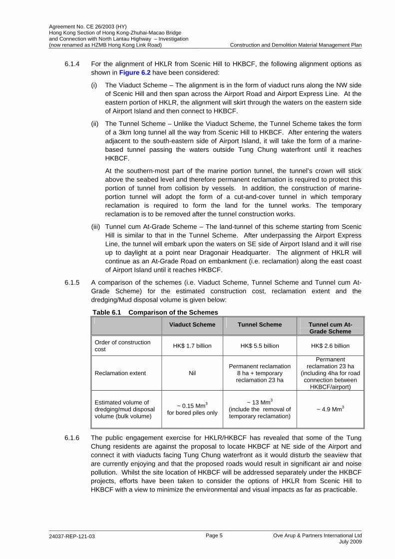
6.1.4 For the alignment of HKLR from Scenic Hill to HKBCF, the following alignment options as shown in Figure 6.2 have been considered:
(i) The Viaduct Scheme – The alignment is in the form of viaduct runs along the NW side of Scenic Hill and then span across the Airport Road and Airport Express Line. At the eastern portion of HKLR, the alignment will skirt through the waters on the eastern side of Airport Island and then connect to HKBCF.
(ii) The Tunnel Scheme – Unlike the Viaduct Scheme, the Tunnel Scheme takes the form of a 3km long tunnel all the way from Scenic Hill to HKBCF. After entering the waters adjacent to the south-eastern side of Airport Island, it will take the form of a marine-based tunnel passing the waters outside Tung Chung waterfront until it reaches HKBCF.
At the southern-most part of the marine portion tunnel, the tunnel’s crown will stick above the seabed level and therefore permanent reclamation is required to protect this portion of tunnel from collision by vessels. In addition, the construction of marine-portion tunnel will adopt the form of a cut-and-cover tunnel in which temporary reclamation is required to form the land for the tunnel works. The temporary reclamation is to be removed after the tunnel construction works.
(iii) Tunnel cum At-Grade Scheme – The land-tunnel of this scheme starting from Scenic Hill is similar to that in the Tunnel Scheme. After underpassing the Airport Express Line, the tunnel will embark upon the waters on SE side of Airport Island and it will rise up to daylight at a point near Dragonair Headquarter. The alignment of HKLR will continue as an At-Grade Road on embankment (i.e. reclamation) along the east coast of Airport Island until it reaches HKBCF.
6.1.5 A comparison of the schemes (i.e. Viaduct Scheme, Tunnel Scheme and Tunnel cum At-Grade Scheme) for the estimated construction cost, reclamation extent and the dredging/Mud disposal volume is given below:
Table 6.1 Comparison of the Schemes Viaduct Scheme Tunnel Scheme Tunnel cum At-
Grade Scheme
Order of construction cost HK$ 1.7 billion HK$ 5.5 billion HK$ 2.6 billion
Reclamation extent Nil Permanent reclamation
8 ha + temporary reclamation 23 ha
Permanent reclamation 23 ha
(including 4ha for road connection between
HKBCF/airport)
Estimated volume of dredging/mud disposal volume (bulk volume)
~ 0.15 Mm3 for bored piles only
~ 13 Mm3 (include the removal of temporary reclamation)
~ 4.9 Mm3
6.1.6 The public engagement exercise for HKLR/HKBCF has revealed that some of the Tung Chung residents are against the proposal to locate HKBCF at NE side of the Airport and connect it with viaducts facing Tung Chung waterfront as it would disturb the seaview that are currently enjoying and that the proposed roads would result in significant air and noise pollution. Whilst the site location of HKBCF will be addressed separately under the HKBCF projects, efforts have been taken to consider the options of HKLR from Scenic Hill to HKBCF with a view to minimize the environmental and visual impacts as far as practicable.

Agreement No. CE 26/2003 (HY) Hong Kong Section of Hong Kong-Zhuhai-Macao Bridge and Connection with North Lantau Highway – Investigation (now renamed as HZMB Hong Kong Link Road) Construction and Demolition Material Management Plan
24037-REP-121-03 Page 6 Ove Arup & Partners International Ltd
July 2009
6.1.7 As Tung Chung residents are against the Viaduct Scheme due to the concerns of environmental and visual impacts, the Viaduct Scheme is not considered further. As shown in Table 6.1 above, the Tunnel cum At-Grade Scheme is advantageous compared with the Tunnel Scheme considering cost, extent of reclamation and volume of dredging/mud-disposal involved. Therefore, the Tunnel cum At-Grade Scheme is recommended for the portion of HKLR from Scenic Hill to HKBCF. In addition, the reclamation in Tunnel cum At-Grade Scheme could also provide the land along the east coastline for the connection road between HKBCF and airport. This could minimise the length of seawall and thus the dredging and filling for seawall if the reclamation for HKLR and the HKBCF’s connection road is integrated.
6.2 Construction method of seawalls
6.2.1 The seawall is a retaining structure to protect the reclaimed fill. Both the dredged and non-dredged options of seawall have been considered for the HKLR. Typical section of the dredged and non-dredged seawall is shown in Figure 6.3.
6.2.2 The design of seawall should achieve a minimum Factor of Safety to ensure the stability against the slip failure and provide adequate bearing capacity to support the seawall without significant settlement. Based on the available ground investigation results, preliminary assessment of the seawall stability and settlement is summarised in the following table:
Evaluation Results
Dredged Option
Non-dredged Option (without ground improvement)
Stability Assessment – in terms of Factor of Safety
Min. 1.34 > 1.3 (OK)
Max. 0.32 << 1.3 (Failed)
Settlement Assessment – in terms of Total Residual Settlement (mm)
Max. 340mm < 500mm (OK)
Min. 2000mm >> 500mm (Failed)
6.2.3 From the above assessment, it was found that the non-dredged option without ground improvement fails to provide sufficient stability and settlement control to the seawall. As a common practice, full-dredging is adopted for forming the seawall base so as to ensure the stability and minimise the settlement of the seawall. However, it is important to consider the feasibility of non-dredged option with ground improvement measure for the seawall with a view to minimize the dredging of marine deposit.
6.2.4 For the non-dredged option with ground improvement measure for seawall, the use of band drains and surcharge is considered to be inadequate as it could not improve the shear strength of marine deposit to ensure the seawall stability. The use of Sand Compaction Pile (SCP) and Deep Cement Mixing (DCM) as the seawall foundation was adopted in some overseas projects. However, there is no track record of the application of SCP and DCM in Hong Kong. The feasibility to adopt SCP or DCM for the seawall foundation will be discussed in the following Sections.
6.2.5 DCM is an applied chemical solidification technique which inserts and mechanically mixes cementing agents with soft soils to create a stiff soil-cement mix. However, it is important to note that the marine application of DCM may result in possible leakage of cement grout into the surrounding waters during the mixing process and this would cause adverse environment impacts. For the land application of DCM after the seawall is constructed, there are difficulties for DCM to penetrate through the rockfill in seawall core. In view of the above, it is considered that application of DCM is not suitable for the seawalls in HKLR.
Agreement No. CE 26/2003 (HY) Hong Kong Section of Hong Kong-Zhuhai-Macao Bridge and Connection with North Lantau Highway – Investigation (now renamed as HZMB Hong Kong Link Road) Construction and Demolition Material Management Plan
24037-REP-121-03 Page 7 Ove Arup & Partners International Ltd
July 2009
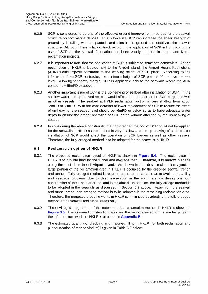
6.2.6 SCP is considered to be one of the effective ground improvement methods for the seawall structure on soft marine deposit. This is because SCP can increase the shear strength of ground by installing well compacted sand piles in the ground and stabilizes the seawall structure. Although there is lack of track record in the application of SCP in Hong Kong, the use of SCP as the seawall foundation has been widely adopted in Japan and Korea reclamation projects.
6.2.7 It is important to note that the application of SCP is subject to some site constraints. As the reclamation of HKLR is located next to the Airport Island, the Airport Height Restrictions (AHR) would impose constraint to the working height of SCP plant. According to the information from SCP contractor, the minimum height of SCP plant is 40m above the sea level. Allowing for safety margin, SCP is applicable only to the seawalls where the AHR contour is +45mPD or above.
6.2.8 Another important issue of SCP is the up-heaving of seabed after installation of SCP. In the shallow water, the up-heaved seabed would affect the operation of the SCP barges as well as other vessels. The seabed at HKLR reclamation portion is very shallow from about -2mPD to -3mPD. With the consideration of lower replacement of SCP to reduce the effect of up-heaving, the seabed level should be -6mPD or below so as to have adequate water depth to ensure the proper operation of SCP barge without affecting by the up-heaving of seabed.
6.2.9 In considering the above constraints, the non-dredged method of SCP could not be applied for the seawalls in HKLR as the seabed is very shallow and the up-heaving of seabed after installation of SCP would affect the operation of SCP barges as well as other vessels. Therefore, the fully-dredged method is to be adopted for the seawalls in HKLR.
6.3 Reclamation option of HKLR
6.3.1 The proposed reclamation layout of HKLR is shown in Figure 6.4. The reclamation in HKLR is to provide land for the tunnel and at-grade road. Therefore, it is narrow in shape along the east shoreline of Airport Island. As shown in the above reclamation layout, a large portion of the reclamation area in HKLR is occupied by the dredged seawall trench and tunnel. Fully dredged method is required at the tunnel area so as to avoid the stability and seepage problems due to deep excavation in the soft materials during open-cut construction of the tunnel after the land is reclaimed. In addition, the fully dredge method is to be adopted in the seawalls as discussed in Section 6.2 above. Apart from the seawall and tunnel areas, non-dredged method is to be adopted in the remaining reclamation area. Therefore, the proposed dredging works in HKLR is minimized by adopting the fully dredged method at the seawall and tunnel areas only.
6.3.2 The envisaged programme of the recommended reclamation method in HKLR is shown in Figure 6.5. The assumed construction rates and the period allowed for the surcharging and the infrastructure works of HKLR is attached in Appendix B.
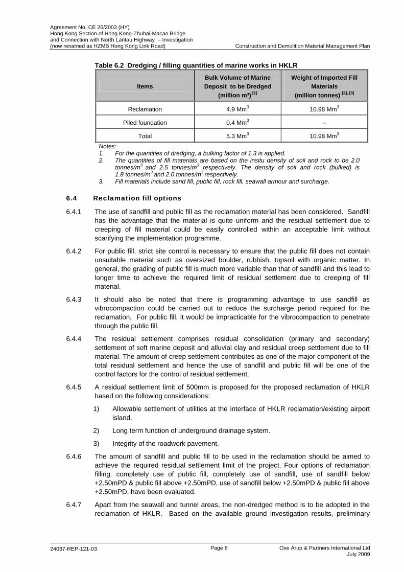
6.3.3 The estimated quantity of dredging and imported filling in HKLR (for both reclamation and pile foundation of marine viaduct) is given in Table 6.2 below:
Agreement No. CE 26/2003 (HY) Hong Kong Section of Hong Kong-Zhuhai-Macao Bridge and Connection with North Lantau Highway – Investigation (now renamed as HZMB Hong Kong Link Road) Construction and Demolition Material Management Plan
24037-REP-121-03 Page 8 Ove Arup & Partners International Ltd
July 2009
Table 6.2 Dredging / filling quantities of marine works in HKLR
Items Bulk Volume of Marine Deposit to be Dredged
(million m³) [1]
Weight of Imported Fill Materials
(million tonnes) [2], [3]
Reclamation 4.9 Mm3 10.98 Mm3
Piled foundation 0.4 Mm3 --
Total 5.3 Mm3 10.98 Mm3 Notes: 1. For the quantities of dredging, a bulking factor of 1.3 is applied. 2. The quantities of fill materials are based on the insitu density of soil and rock to be 2.0
tonnes/m3 and 2.5 tonnes/m3 respectively. The density of soil and rock (bulked) is 1.8 tonnes/m3 and 2.0 tonnes/m3 respectively.
3. Fill materials include sand fill, public fill, rock fill, seawall armour and surcharge.
6.4 Reclamation fill options
6.4.1 The use of sandfill and public fill as the reclamation material has been considered. Sandfill has the advantage that the material is quite uniform and the residual settlement due to creeping of fill material could be easily controlled within an acceptable limit without scarifying the implementation programme.
6.4.2 For public fill, strict site control is necessary to ensure that the public fill does not contain unsuitable material such as oversized boulder, rubbish, topsoil with organic matter. In general, the grading of public fill is much more variable than that of sandfill and this lead to longer time to achieve the required limit of residual settlement due to creeping of fill material.
6.4.3 It should also be noted that there is programming advantage to use sandfill as vibrocompaction could be carried out to reduce the surcharge period required for the reclamation. For public fill, it would be impracticable for the vibrocompaction to penetrate through the public fill.
6.4.4 The residual settlement comprises residual consolidation (primary and secondary) settlement of soft marine deposit and alluvial clay and residual creep settlement due to fill material. The amount of creep settlement contributes as one of the major component of the total residual settlement and hence the use of sandfill and public fill will be one of the control factors for the control of residual settlement.
6.4.5 A residual settlement limit of 500mm is proposed for the proposed reclamation of HKLR based on the following considerations:
1) Allowable settlement of utilities at the interface of HKLR reclamation/existing airport island.
2) Long term function of underground drainage system.
3) Integrity of the roadwork pavement.
6.4.6 The amount of sandfill and public fill to be used in the reclamation should be aimed to achieve the required residual settlement limit of the project. Four options of reclamation filling: completely use of public fill, completely use of sandfill, use of sandfill below +2.50mPD & public fill above +2.50mPD, use of sandfill below +2.50mPD & public fill above +2.50mPD, have been evaluated.
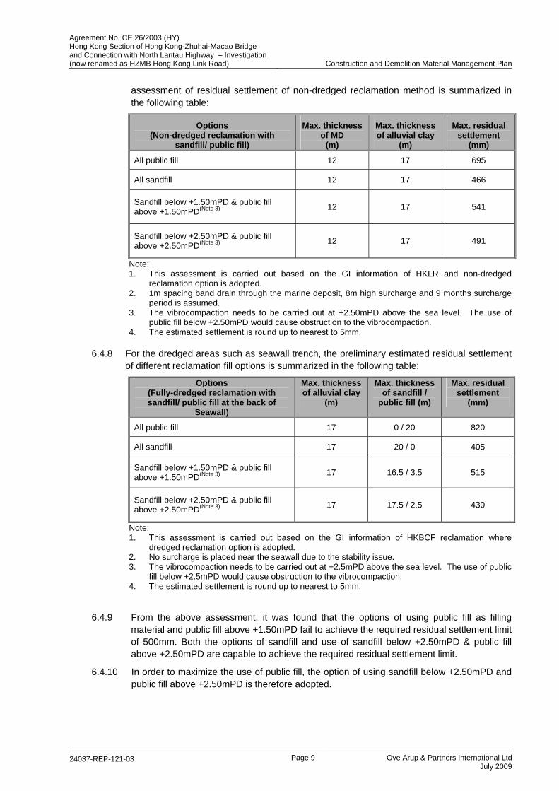
6.4.7 Apart from the seawall and tunnel areas, the non-dredged method is to be adopted in the reclamation of HKLR. Based on the available ground investigation results, preliminary
Agreement No. CE 26/2003 (HY) Hong Kong Section of Hong Kong-Zhuhai-Macao Bridge and Connection with North Lantau Highway – Investigation (now renamed as HZMB Hong Kong Link Road) Construction and Demolition Material Management Plan
24037-REP-121-03 Page 9 Ove Arup & Partners International Ltd
July 2009
assessment of residual settlement of non-dredged reclamation method is summarized in the following table:
Options (Non-dredged reclamation with
sandfill/ public fill)
Max. thickness of MD
(m)
Max. thickness of alluvial clay
(m)
Max. residual settlement
(mm)
All public fill 12 17 695
All sandfill 12 17 466
Sandfill below +1.50mPD & public fill above +1.50mPD(Note 3) 12 17 541
Sandfill below +2.50mPD & public fill above +2.50mPD(Note 3) 12 17 491
Note: 1. This assessment is carried out based on the GI information of HKLR and non-dredged
reclamation option is adopted. 2. 1m spacing band drain through the marine deposit, 8m high surcharge and 9 months surcharge
period is assumed. 3. The vibrocompaction needs to be carried out at +2.50mPD above the sea level. The use of
public fill below +2.50mPD would cause obstruction to the vibrocompaction. 4. The estimated settlement is round up to nearest to 5mm.
6.4.8 For the dredged areas such as seawall trench, the preliminary estimated residual settlement of different reclamation fill options is summarized in the following table:
Options (Fully-dredged reclamation with sandfill/ public fill at the back of
Seawall)
Max. thickness of alluvial clay
(m)
Max. thickness of sandfill /
public fill (m)
Max. residual settlement
(mm)
All public fill 17 0 / 20 820
All sandfill 17 20 / 0 405
Sandfill below +1.50mPD & public fill above +1.50mPD(Note 3) 17 16.5 / 3.5 515
Sandfill below +2.50mPD & public fill above +2.50mPD(Note 3) 17 17.5 / 2.5 430
Note: 1. This assessment is carried out based on the GI information of HKBCF reclamation where
dredged reclamation option is adopted. 2. No surcharge is placed near the seawall due to the stability issue. 3. The vibrocompaction needs to be carried out at +2.5mPD above the sea level. The use of public
fill below +2.5mPD would cause obstruction to the vibrocompaction. 4. The estimated settlement is round up to nearest to 5mm.
6.4.9 From the above assessment, it was found that the options of using public fill as filling material and public fill above +1.50mPD fail to achieve the required residual settlement limit of 500mm. Both the options of sandfill and use of sandfill below +2.50mPD & public fill above +2.50mPD are capable to achieve the required residual settlement limit.
6.4.10 In order to maximize the use of public fill, the option of using sandfill below +2.50mPD and public fill above +2.50mPD is therefore adopted.
Agreement No. CE 26/2003 (HY) Hong Kong Section of Hong Kong-Zhuhai-Macao Bridge and Connection with North Lantau Highway – Investigation (now renamed as HZMB Hong Kong Link Road) Construction and Demolition Material Management Plan
24037-REP-121-03 Page 10 Ove Arup & Partners International Ltd
July 2009
7 MANAGEMENT OF C&D MATERIALS 7.1 C&D Materials Quantities
7.1.1 The C&D materials generated from the HKLR project will come from the following major items of works:
Excavation for the bored piles of marine and land portions of viaducts; and
Excavation for the tunnels and associated structures.
7.1.2 In addition, substantial amount of filling materials would be imported for the construction of seawalls and reclamation. A breakdown of the estimated quantities of public fill and C&D waste generated and the filling material required in this Project is summarized in the following Sections.
7.2 Generated Public Fill Material
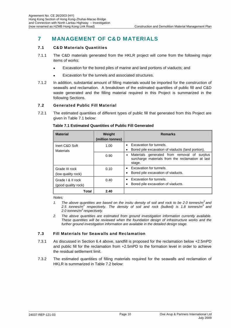
7.2.1 The estimated quantities of different types of public fill that generated from this Project are given in Table 7.1 below:
Table 7.1 Estimated Quantities of Public Fill Generated
Material Weight (million tonnes)
Remarks
1.00 • Excavation for tunnels. • Bored pile excavation of viaducts (land portion).
Inert C&D Soft Materials
0.90 • Materials generated from removal of surplus surcharge materials from the reclamation at last stage.
Grade III rock (low quality rock)
0.10 • Excavation for tunnels. • Bored pile excavation of viaducts.
Grade I & II rock (good quality rock)
0.40 • Excavation for tunnels. • Bored pile excavation of viaducts.
Total 2.40
Notes: 1. The above quantities are based on the insitu density of soil and rock to be 2.0 tonnes/m3 and
2.5 tonnes/m3 respectively. The density of soil and rock (bulked) is 1.8 tonnes/m3 and 2.0 tonnes/m3 respectively.
2. The above quantities are estimated from ground investigation information currently available. These quantities will be reviewed when the foundation design of infrastructure works and the further ground investigation information are available in the detailed design stage.
7.3 Fill Materials for Seawalls and Reclamation
7.3.1 As discussed in Section 6.4 above, sandfill is proposed for the reclamation below +2.5mPD and public fill for the reclamation from +2.5mPD to the formation level in order to achieve the residual settlement limit.
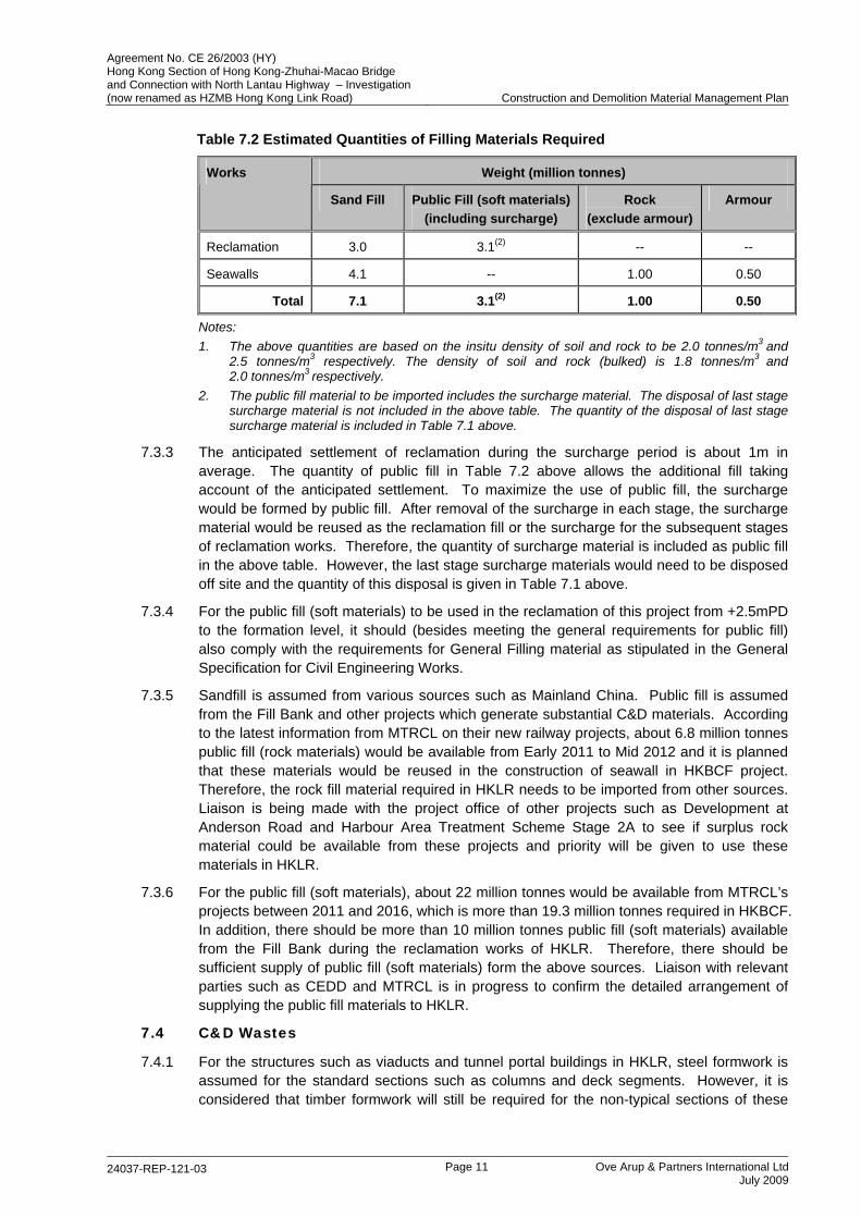
7.3.2 The estimated quantities of filling materials required for the seawalls and reclamation of HKLR is summarized in Table 7.2 below:
Agreement No. CE 26/2003 (HY) Hong Kong Section of Hong Kong-Zhuhai-Macao Bridge and Connection with North Lantau Highway – Investigation (now renamed as HZMB Hong Kong Link Road) Construction and Demolition Material Management Plan
24037-REP-121-03 Page 11 Ove Arup & Partners International Ltd
July 2009
Table 7.2 Estimated Quantities of Filling Materials Required
Weight (million tonnes) Works
Sand Fill Public Fill (soft materials) (including surcharge)
Rock (exclude armour)
Armour
Reclamation 3.0 3.1(2) -- --
Seawalls 4.1 -- 1.00 0.50
Total 7.1 3.1(2) 1.00 0.50
Notes: 1. The above quantities are based on the insitu density of soil and rock to be 2.0 tonnes/m3 and
2.5 tonnes/m3 respectively. The density of soil and rock (bulked) is 1.8 tonnes/m3 and 2.0 tonnes/m3 respectively.
2. The public fill material to be imported includes the surcharge material. The disposal of last stage surcharge material is not included in the above table. The quantity of the disposal of last stage surcharge material is included in Table 7.1 above.
7.3.3 The anticipated settlement of reclamation during the surcharge period is about 1m in average. The quantity of public fill in Table 7.2 above allows the additional fill taking account of the anticipated settlement. To maximize the use of public fill, the surcharge would be formed by public fill. After removal of the surcharge in each stage, the surcharge material would be reused as the reclamation fill or the surcharge for the subsequent stages of reclamation works. Therefore, the quantity of surcharge material is included as public fill in the above table. However, the last stage surcharge materials would need to be disposed off site and the quantity of this disposal is given in Table 7.1 above.
7.3.4 For the public fill (soft materials) to be used in the reclamation of this project from +2.5mPD to the formation level, it should (besides meeting the general requirements for public fill) also comply with the requirements for General Filling material as stipulated in the General Specification for Civil Engineering Works.
7.3.5 Sandfill is assumed from various sources such as Mainland China. Public fill is assumed from the Fill Bank and other projects which generate substantial C&D materials. According to the latest information from MTRCL on their new railway projects, about 6.8 million tonnes public fill (rock materials) would be available from Early 2011 to Mid 2012 and it is planned that these materials would be reused in the construction of seawall in HKBCF project. Therefore, the rock fill material required in HKLR needs to be imported from other sources. Liaison is being made with the project office of other projects such as Development at Anderson Road and Harbour Area Treatment Scheme Stage 2A to see if surplus rock material could be available from these projects and priority will be given to use these materials in HKLR.
7.3.6 For the public fill (soft materials), about 22 million tonnes would be available from MTRCL’s projects between 2011 and 2016, which is more than 19.3 million tonnes required in HKBCF. In addition, there should be more than 10 million tonnes public fill (soft materials) available from the Fill Bank during the reclamation works of HKLR. Therefore, there should be sufficient supply of public fill (soft materials) form the above sources. Liaison with relevant parties such as CEDD and MTRCL is in progress to confirm the detailed arrangement of supplying the public fill materials to HKLR.
7.4 C&D Wastes
7.4.1 For the structures such as viaducts and tunnel portal buildings in HKLR, steel formwork is assumed for the standard sections such as columns and deck segments. However, it is considered that timber formwork will still be required for the non-typical sections of these
Agreement No. CE 26/2003 (HY) Hong Kong Section of Hong Kong-Zhuhai-Macao Bridge and Connection with North Lantau Highway – Investigation (now renamed as HZMB Hong Kong Link Road) Construction and Demolition Material Management Plan
24037-REP-121-03 Page 12 Ove Arup & Partners International Ltd
July 2009
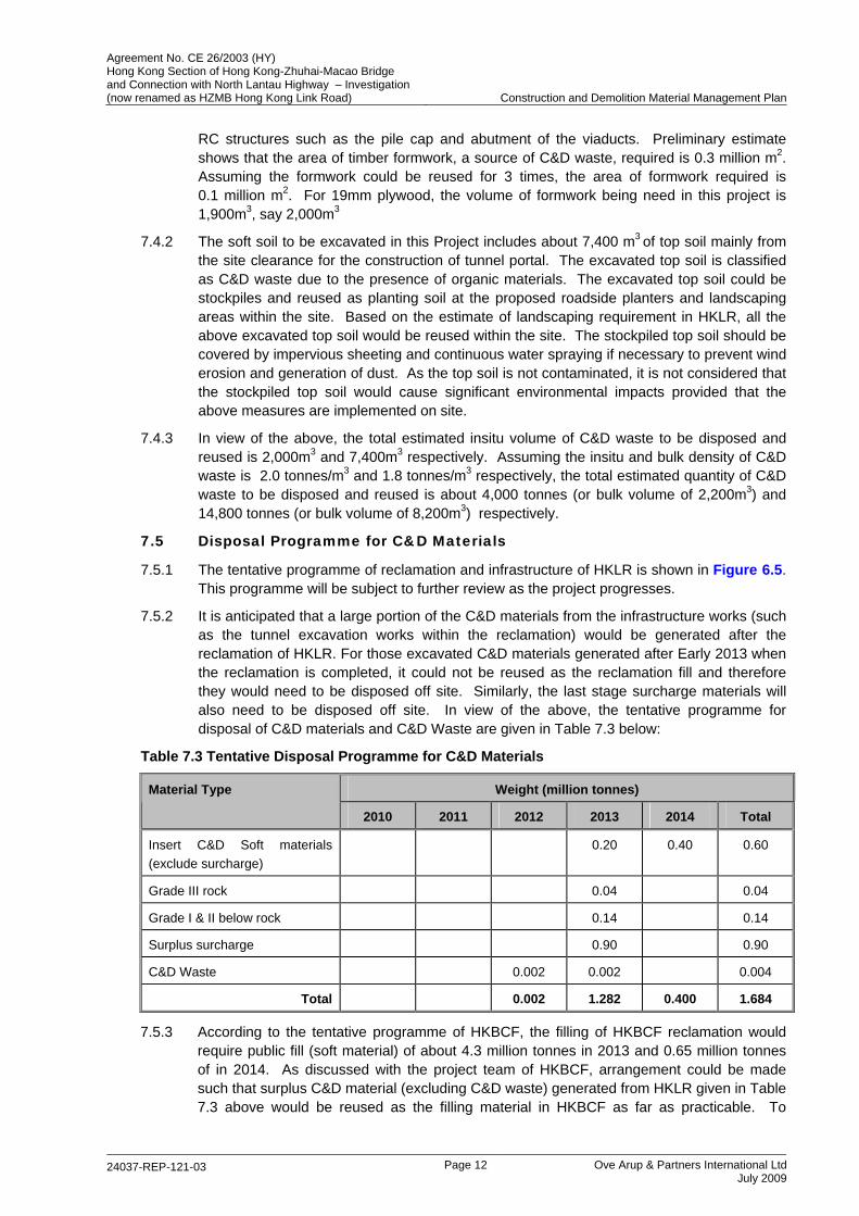
RC structures such as the pile cap and abutment of the viaducts. Preliminary estimate shows that the area of timber formwork, a source of C&D waste, required is 0.3 million m2. Assuming the formwork could be reused for 3 times, the area of formwork required is 0.1 million m2. For 19mm plywood, the volume of formwork being need in this project is 1,900m3, say 2,000m3
7.4.2 The soft soil to be excavated in this Project includes about 7,400 m3 of top soil mainly from the site clearance for the construction of tunnel portal. The excavated top soil is classified as C&D waste due to the presence of organic materials. The excavated top soil could be stockpiles and reused as planting soil at the proposed roadside planters and landscaping areas within the site. Based on the estimate of landscaping requirement in HKLR, all the above excavated top soil would be reused within the site. The stockpiled top soil should be covered by impervious sheeting and continuous water spraying if necessary to prevent wind erosion and generation of dust. As the top soil is not contaminated, it is not considered that the stockpiled top soil would cause significant environmental impacts provided that the above measures are implemented on site.
7.4.3 In view of the above, the total estimated insitu volume of C&D waste to be disposed and reused is 2,000m3 and 7,400m3 respectively. Assuming the insitu and bulk density of C&D waste is 2.0 tonnes/m3 and 1.8 tonnes/m3 respectively, the total estimated quantity of C&D waste to be disposed and reused is about 4,000 tonnes (or bulk volume of 2,200m3) and 14,800 tonnes (or bulk volume of 8,200m3) respectively.
7.5 Disposal Programme for C&D Materials
7.5.1 The tentative programme of reclamation and infrastructure of HKLR is shown in Figure 6.5. This programme will be subject to further review as the project progresses.
7.5.2 It is anticipated that a large portion of the C&D materials from the infrastructure works (such as the tunnel excavation works within the reclamation) would be generated after the reclamation of HKLR. For those excavated C&D materials generated after Early 2013 when the reclamation is completed, it could not be reused as the reclamation fill and therefore they would need to be disposed off site. Similarly, the last stage surcharge materials will also need to be disposed off site. In view of the above, the tentative programme for disposal of C&D materials and C&D Waste are given in Table 7.3 below:
Table 7.3 Tentative Disposal Programme for C&D Materials
Weight (million tonnes) Material Type
2010 2011 2012 2013 2014 Total
Insert C&D Soft materials (exclude surcharge)
0.20 0.40 0.60
Grade III rock 0.04 0.04
Grade I & II below rock 0.14 0.14
Surplus surcharge 0.90 0.90
C&D Waste 0.002 0.002 0.004
Total 0.002 1.282 0.400 1.684
7.5.3 According to the tentative programme of HKBCF, the filling of HKBCF reclamation would require public fill (soft material) of about 4.3 million tonnes in 2013 and 0.65 million tonnes of in 2014. As discussed with the project team of HKBCF, arrangement could be made such that surplus C&D material (excluding C&D waste) generated from HKLR given in Table 7.3 above would be reused as the filling material in HKBCF as far as practicable. To
Agreement No. CE 26/2003 (HY) Hong Kong Section of Hong Kong-Zhuhai-Macao Bridge and Connection with North Lantau Highway – Investigation (now renamed as HZMB Hong Kong Link Road) Construction and Demolition Material Management Plan
24037-REP-121-03 Page 13 Ove Arup & Partners International Ltd
July 2009
maximum the reuse of surplus C&D material from HKLR, the rock materials would be broken into smaller size to meet the filling requirement of HKBCF. The above arrangement will be reviewed when the detailed construction programme of HKLR and HKBCF is available.
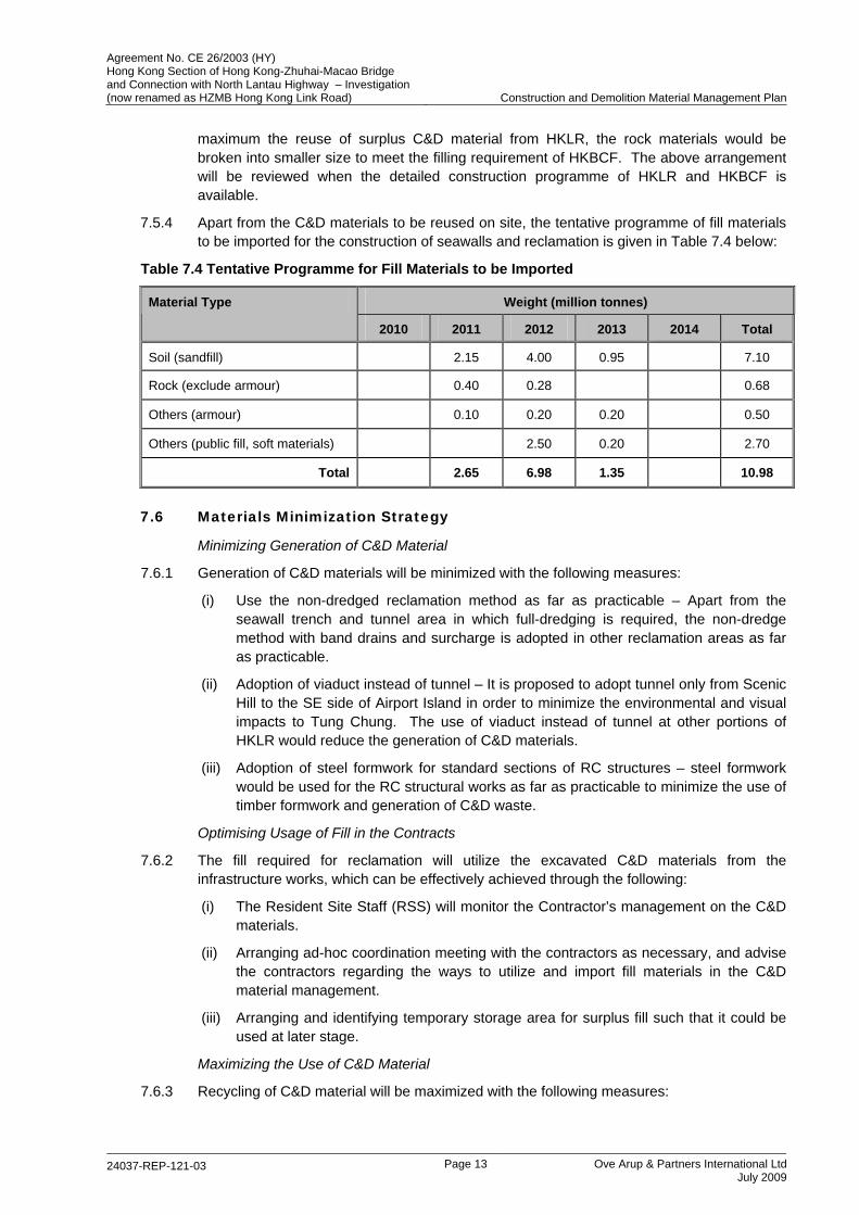
7.5.4 Apart from the C&D materials to be reused on site, the tentative programme of fill materials to be imported for the construction of seawalls and reclamation is given in Table 7.4 below:
Table 7.4 Tentative Programme for Fill Materials to be Imported
Weight (million tonnes) Material Type
2010 2011 2012 2013 2014 Total
Soil (sandfill) 2.15 4.00 0.95 7.10
Rock (exclude armour) 0.40 0.28 0.68
Others (armour) 0.10 0.20 0.20 0.50
Others (public fill, soft materials) 2.50 0.20 2.70
Total 2.65 6.98 1.35 10.98
7.6 Materials Minimization Strategy
Minimizing Generation of C&D Material
7.6.1 Generation of C&D materials will be minimized with the following measures:
(i) Use the non-dredged reclamation method as far as practicable – Apart from the seawall trench and tunnel area in which full-dredging is required, the non-dredge method with band drains and surcharge is adopted in other reclamation areas as far as practicable.
(ii) Adoption of viaduct instead of tunnel – It is proposed to adopt tunnel only from Scenic Hill to the SE side of Airport Island in order to minimize the environmental and visual impacts to Tung Chung. The use of viaduct instead of tunnel at other portions of HKLR would reduce the generation of C&D materials.
(iii) Adoption of steel formwork for standard sections of RC structures – steel formwork would be used for the RC structural works as far as practicable to minimize the use of timber formwork and generation of C&D waste.
Optimising Usage of Fill in the Contracts
7.6.2 The fill required for reclamation will utilize the excavated C&D materials from the infrastructure works, which can be effectively achieved through the following:
(i) The Resident Site Staff (RSS) will monitor the Contractor’s management on the C&D materials.
(ii) Arranging ad-hoc coordination meeting with the contractors as necessary, and advise the contractors regarding the ways to utilize and import fill materials in the C&D material management.
(iii) Arranging and identifying temporary storage area for surplus fill such that it could be used at later stage.
Maximizing the Use of C&D Material
7.6.3 Recycling of C&D material will be maximized with the following measures:
Agreement No. CE 26/2003 (HY) Hong Kong Section of Hong Kong-Zhuhai-Macao Bridge and Connection with North Lantau Highway – Investigation (now renamed as HZMB Hong Kong Link Road) Construction and Demolition Material Management Plan
24037-REP-121-03 Page 14 Ove Arup & Partners International Ltd
July 2009
(i) The excavated top soil during the site clearance works can be temporarily stockpiled subject to the availability of temporary storage areas to be identified. The stockpiled top soil will be reused at the proposed landscaping areas of HKLR.
(ii) Arrangement will be made to reuse the surplus C&D material generated from HKLR as the filling materials in HKBCF as far as practicable. This will be reviewed when the detailed construction programme of HKLR and HKBCF is available.
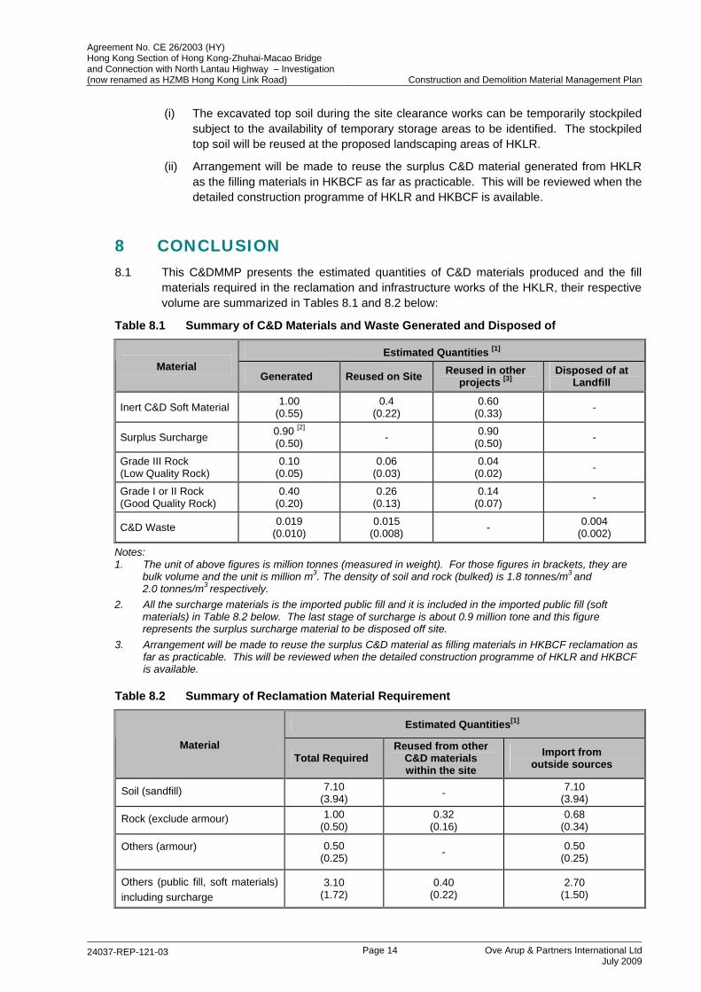
8 CONCLUSION 8.1 This C&DMMP presents the estimated quantities of C&D materials produced and the fill
materials required in the reclamation and infrastructure works of the HKLR, their respective volume are summarized in Tables 8.1 and 8.2 below:
Table 8.1 Summary of C&D Materials and Waste Generated and Disposed of
Estimated Quantities [1] Material
Generated Reused on Site Reused in other projects [3]
Disposed of at Landfill
Inert C&D Soft Material 1.00 (0.55)
0.4 (0.22)
0.60 (0.33) -
Surplus Surcharge 0.90 [2] (0.50) - 0.90
(0.50) -
Grade III Rock (Low Quality Rock)
0.10 (0.05)
0.06 (0.03)
0.04 (0.02) -
Grade I or II Rock (Good Quality Rock)
0.40 (0.20)
0.26 (0.13)
0.14 (0.07) -
C&D Waste 0.019 (0.010)
0.015 (0.008) - 0.004
(0.002)
Notes: 1. The unit of above figures is million tonnes (measured in weight). For those figures in brackets, they are
bulk volume and the unit is million m3. The density of soil and rock (bulked) is 1.8 tonnes/m3 and 2.0 tonnes/m3 respectively.
2. All the surcharge materials is the imported public fill and it is included in the imported public fill (soft materials) in Table 8.2 below. The last stage of surcharge is about 0.9 million tone and this figure represents the surplus surcharge material to be disposed off site.
3. Arrangement will be made to reuse the surplus C&D material as filling materials in HKBCF reclamation as far as practicable. This will be reviewed when the detailed construction programme of HKLR and HKBCF is available.
Table 8.2 Summary of Reclamation Material Requirement
Estimated Quantities[1]
Material Total Required
Reused from other C&D materials within the site
Import from outside sources
Soil (sandfill) 7.10 (3.94) - 7.10
(3.94)
Rock (exclude armour) 1.00 (0.50)
0.32 (0.16)
0.68 (0.34)
Others (armour) 0.50 (0.25) - 0.50
(0.25)
Others (public fill, soft materials) including surcharge
3.10 (1.72)
0.40 (0.22)
2.70 (1.50)
Agreement No. CE 26/2003 (HY) Hong Kong Section of Hong Kong-Zhuhai-Macao Bridge and Connection with North Lantau Highway – Investigation (now renamed as HZMB Hong Kong Link Road) Construction and Demolition Material Management Plan
24037-REP-121-03 Page 15 Ove Arup & Partners International Ltd
July 2009
Notes: 1. The unit of above figures is million tonnes (measured in weight). For those figures in brackets, they are
bulk volume and the unit is million m3. The density of soil and rock (bulked) is 1.8 tonnes/m3 and 2.0 tonnes/m3 respectively.
8.2 Various means to minimize the C&D materials generation and to maximize the reuse of C&D materials have been considered, as discussed in Section 7.6 above.
9 RECOMMENDATION 9.1 This report provided the estimated quantities of C&D materials that would be generated and
used in this project. It is envisaged that detailed figure would be refined slightly during the detailed design in reviewing and updating this C&DMMP accordingly. To this, the following actions are recommended:
(1) Further review of the programme of HKLR and HKBCF will be carried out such that arrangement could be made to reuse the surplus C&D materials from HKLR in HKBCF reclamation as far as practicable.
(2) Continue liaison with MTRCL and other relevant parties to agree the quantities and arrangement of delivery the public fill materials generated from their projects for use as reclamation fill in HKLR.
(3) This C&DMMP shall be regularly reviewed and updated during the detailed design as well as construction stage. The construction work on site should also be closely monitored.
(4) Appropriate specification should be included in the contract document to control the generation of C&D materials.
(5) The resident site staff supervising the reclamation work should be fully aware of this plan and closely monitor the works on site such that recommendations in this plan would be duly carried out.
(6) This plan should be provided to the contractor in due course, probably at an early stage of the construction in the preparation of Waste Management Plan.
APPENDIX A Tentative Implementation Programme of HKLR
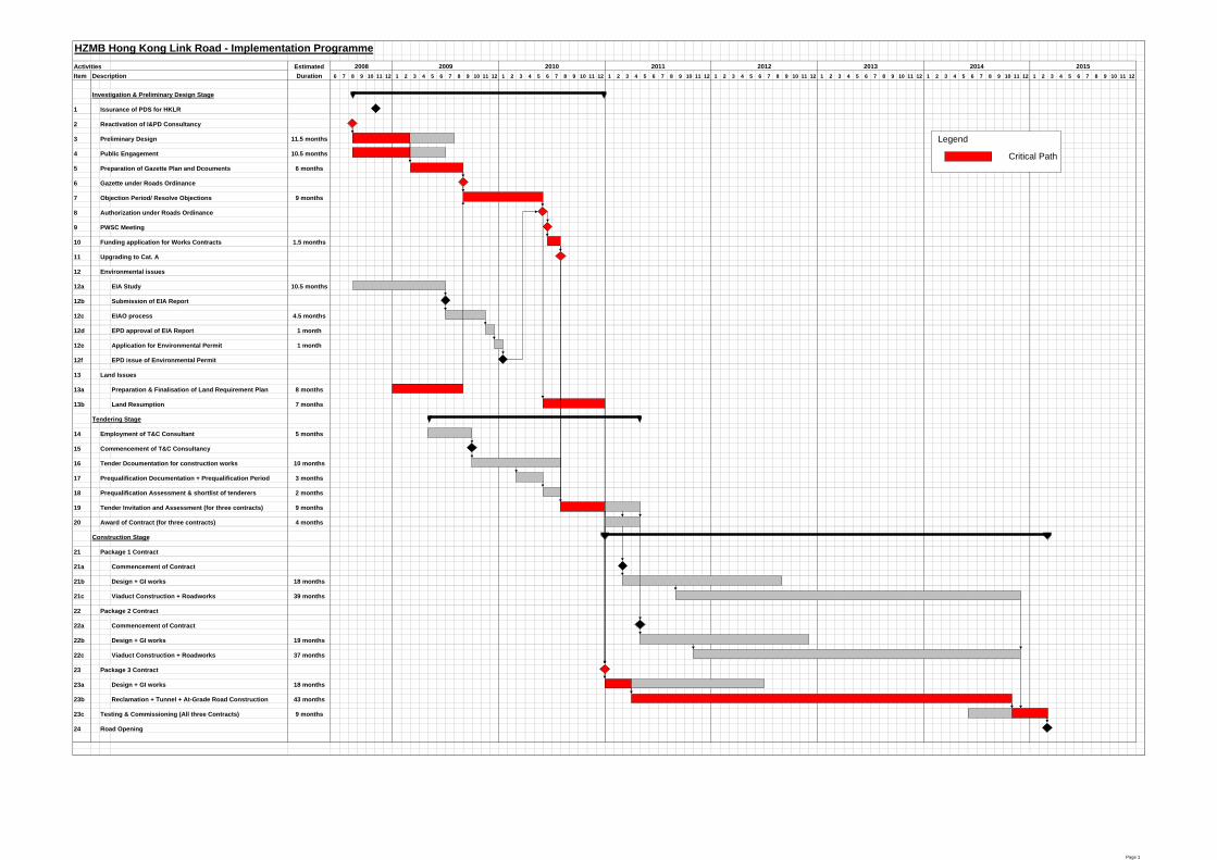
HZMB Hong Kong Link Road - Implementation ProgrammeActivities EstimatedItem Description Duration 6 7 8 9 10 11 12 1 2 3 4 5 6 7 8 9 10 11 12 1 2 3 4 5 6 7 8 9 10 11 12 1 2 3 4 5 6 7 8 9 10 11 12 1 2 3 4 5 6 7 8 9 10 11 12 1 2 3 4 5 6 7 8 9 10 11 12 1 2 3 4 5 6 7 8 9 10 11 12 1 2 3 4 5 6 7 8 9 10 11 12
Investigation & Preliminary Design Stage
1 Issurance of PDS for HKLR
2 Reactivation of I&PD Consultancy
3 Preliminary Design 11.5 months
4 Public Engagement 10.5 months
5 Preparation of Gazette Plan and Dcouments 6 months
6 Gazette under Roads Ordinance
7 Objection Period/ Resolve Objections 9 months
8 Authorization under Roads Ordinance
9 PWSC Meeting
10 Funding application for Works Contracts 1.5 months
11 Upgrading to Cat. A
12 Environmental issues
12a EIA Study 10.5 months
12b Submission of EIA Report
12c EIAO process 4.5 months
12d EPD approval of EIA Report 1 month
12e Application for Environmental Permit 1 month
12f EPD issue of Environmental Permit
13 Land Issues
13a Preparation & Finalisation of Land Requirement Plan 8 months
13b Land Resumption 7 months
Tendering Stage
14 Employment of T&C Consultant 5 months
15 Commencement of T&C Consultancy
16 Tender Dcoumentation for construction works 10 months
17 Prequalification Documentation + Prequalification Period 3 months
18 Prequalification Assessment & shortlist of tenderers 2 months
19 Tender Invitation and Assessment (for three contracts) 9 months
20 Award of Contract (for three contracts) 4 months
Construction Stage
21 Package 1 Contract
21a Commencement of Contract
21b Design + GI works 18 months
21c Viaduct Construction + Roadworks 39 months
22 Package 2 Contract
22a Commencement of Contract
22b Design + GI works 19 months
22c Viaduct Construction + Roadworks 37 months
23 Package 3 Contract
23a Design + GI works 18 months
23b Reclamation + Tunnel + At-Grade Road Construction 43 months
23c Testing & Commissioning (All three Contracts) 9 months
24 Road Opening
2008 2009 2010 2011 201420132012 2015
Legend
Critical Path
Page 1

APPENDIX B Assumed Construction Rates and Period Allowed in the Programme
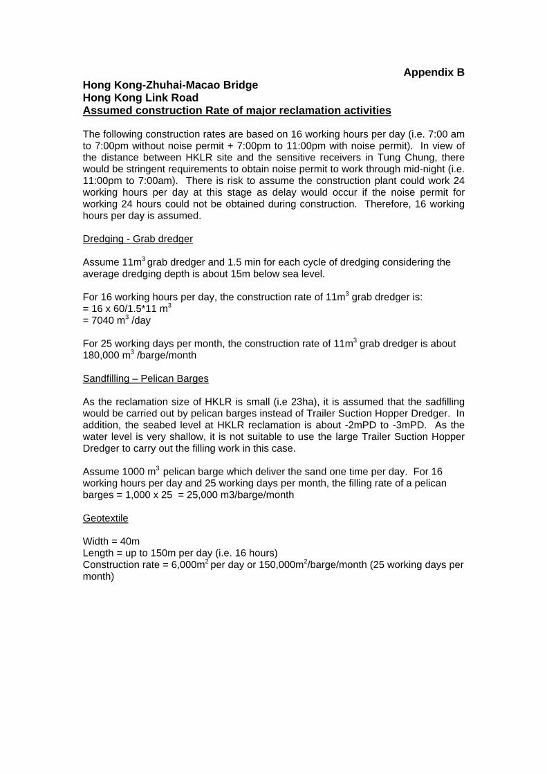
Appendix B Hong Kong-Zhuhai-Macao Bridge Hong Kong Link Road Assumed construction Rate of major reclamation activities The following construction rates are based on 16 working hours per day (i.e. 7:00 am to 7:00pm without noise permit + 7:00pm to 11:00pm with noise permit). In view of the distance between HKLR site and the sensitive receivers in Tung Chung, there would be stringent requirements to obtain noise permit to work through mid-night (i.e. 11:00pm to 7:00am). There is risk to assume the construction plant could work 24 working hours per day at this stage as delay would occur if the noise permit for working 24 hours could not be obtained during construction. Therefore, 16 working hours per day is assumed. Dredging - Grab dredger Assume 11m3 grab dredger and 1.5 min for each cycle of dredging considering the average dredging depth is about 15m below sea level. For 16 working hours per day, the construction rate of 11m3 grab dredger is: = 16 x 60/1.5*11 m3 = 7040 m3 /day For 25 working days per month, the construction rate of 11m3 grab dredger is about 180,000 m3 /barge/month Sandfilling – Pelican Barges As the reclamation size of HKLR is small (i.e 23ha), it is assumed that the sadfilling would be carried out by pelican barges instead of Trailer Suction Hopper Dredger. In addition, the seabed level at HKLR reclamation is about -2mPD to -3mPD. As the water level is very shallow, it is not suitable to use the large Trailer Suction Hopper Dredger to carry out the filling work in this case. Assume 1000 m3 pelican barge which deliver the sand one time per day. For 16 working hours per day and 25 working days per month, the filling rate of a pelican barges = 1,000 x 25 = 25,000 m3/barge/month Geotextile Width = 40m Length = up to 150m per day (i.e. 16 hours) Construction rate = 6,000m2 per day or 150,000m2/barge/month (25 working days per month)
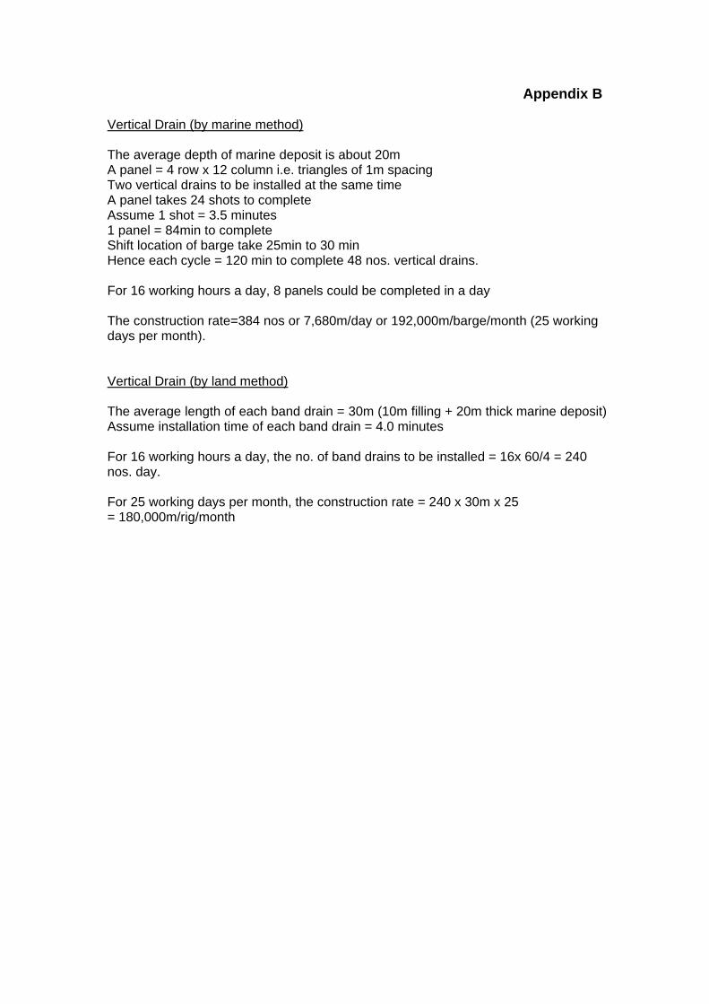
Appendix B Vertical Drain (by marine method) The average depth of marine deposit is about 20m A panel = 4 row x 12 column i.e. triangles of 1m spacing Two vertical drains to be installed at the same time A panel takes 24 shots to complete Assume 1 shot = 3.5 minutes 1 panel = 84min to complete Shift location of barge take 25min to 30 min Hence each cycle = 120 min to complete 48 nos. vertical drains. For 16 working hours a day, 8 panels could be completed in a day The construction rate=384 nos or 7,680m/day or 192,000m/barge/month (25 working days per month). Vertical Drain (by land method) The average length of each band drain = 30m (10m filling + 20m thick marine deposit) Assume installation time of each band drain = 4.0 minutes For 16 working hours a day, the no. of band drains to be installed = 16x 60/4 = 240 nos. day. For 25 working days per month, the construction rate = 240 x 30m x 25 = 180,000m/rig/month
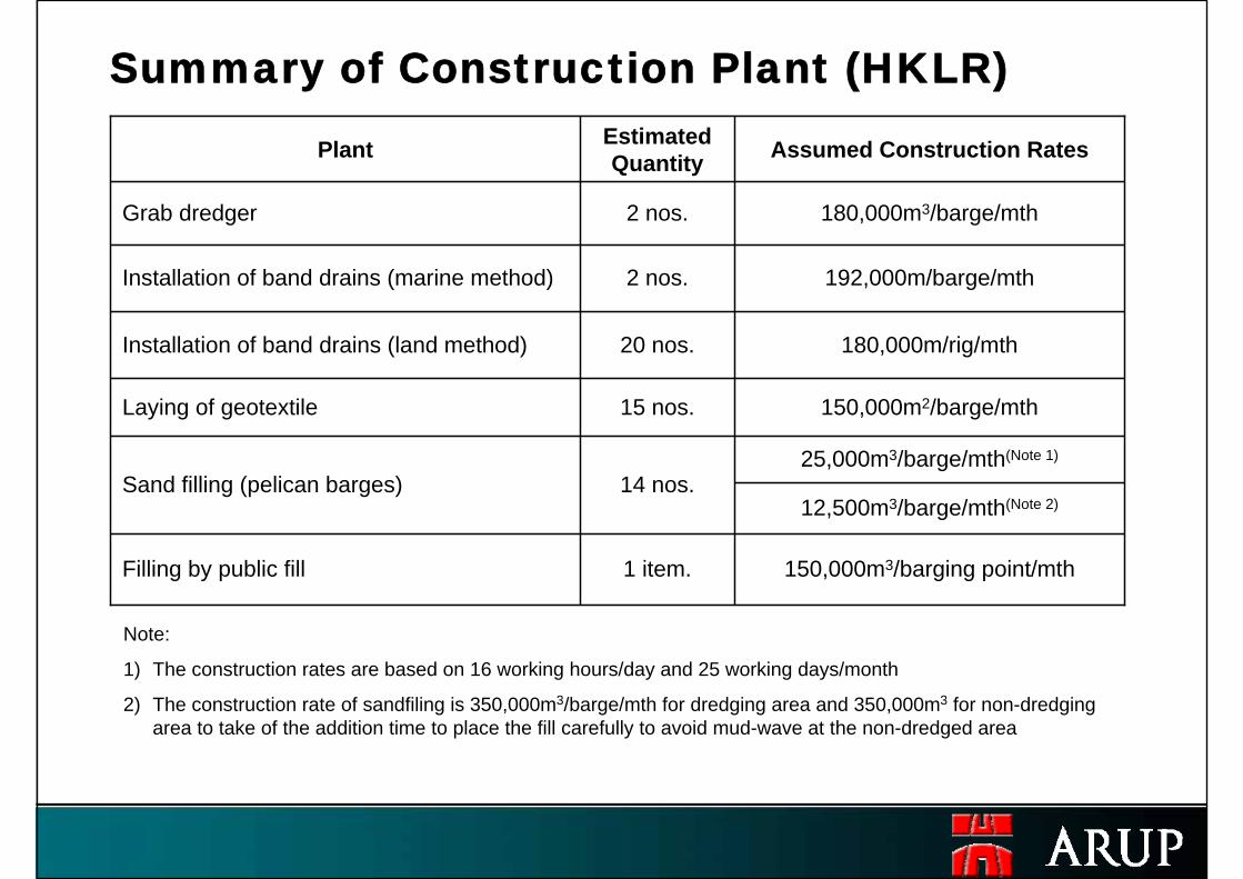
12,500m3/barge/mth(Note 2)
1 item.
14 nos.
15 nos.
20 nos.
2 nos.
2 nos.
Estimated Quantity
180,000m/rig/mthInstallation of band drains (land method)
192,000m/barge/mthInstallation of band drains (marine method)
150,000m2/barge/mthLaying of geotextile
25,000m3/barge/mth(Note 1)
Sand filling (pelican barges)
150,000m3/barging point/mthFilling by public fill
Plant Assumed Construction Rates
Grab dredger 180,000m3/barge/mth
Summary of Construction Plant (HKLR)
Note:
1) The construction rates are based on 16 working hours/day and 25 working days/month
2) The construction rate of sandfiling is 350,000m3/barge/mth for dredging area and 350,000m3 for non-dredging area to take of the addition time to place the fill carefully to avoid mud-wave at the non-dredged area
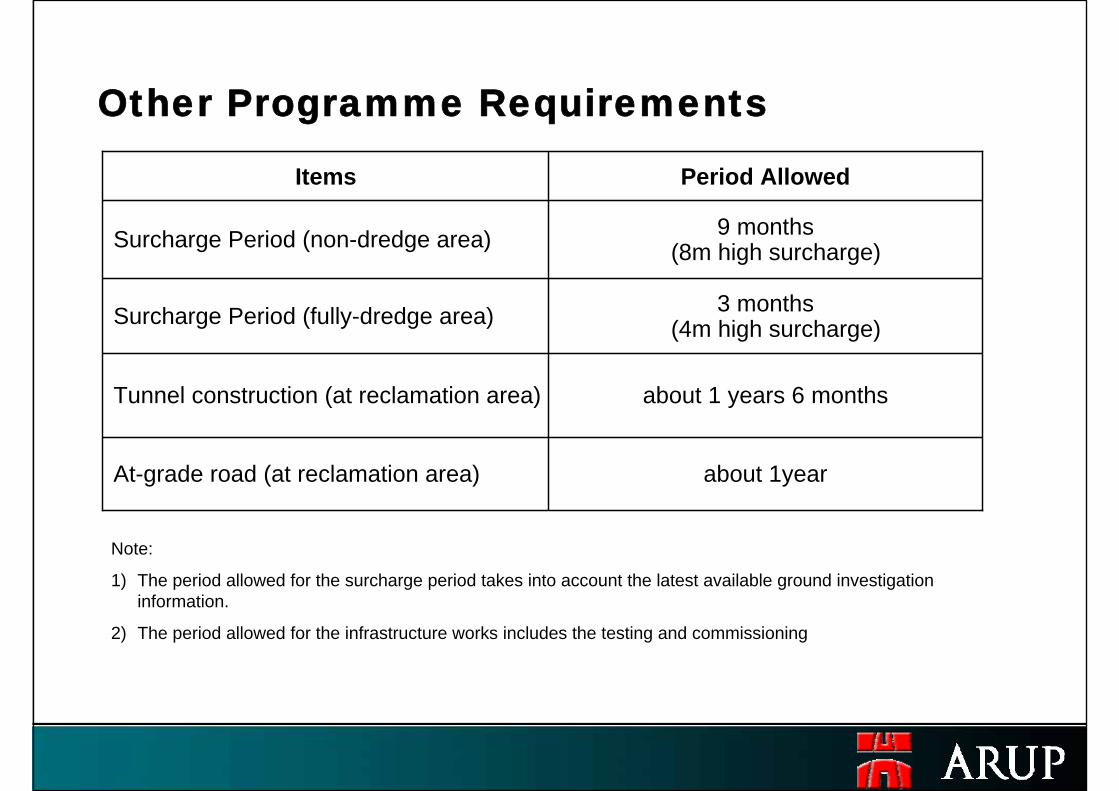
about 1 years 6 monthsTunnel construction (at reclamation area)
3 months (4m high surcharge)Surcharge Period (fully-dredge area)
about 1year At-grade road (at reclamation area)
Items Period Allowed
Surcharge Period (non-dredge area) 9 months (8m high surcharge)
Other Programme Requirements
Note:
1) The period allowed for the surcharge period takes into account the latest available ground investigation information.
2) The period allowed for the infrastructure works includes the testing and commissioning

FIGURES
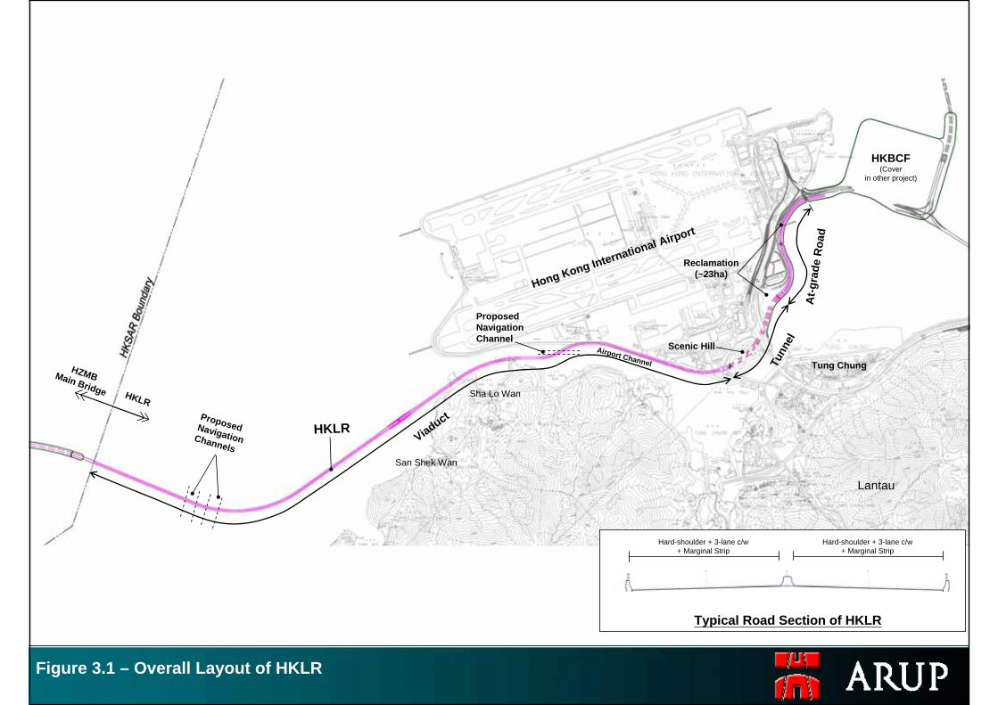
Figure 3.1 – Overall Layout of HKLR
Viaduct
Tunn
el
At-g
rade
Roa
d
HKBCF(Cover
in other project)
HZMBMain Bridge HKLR
Typical Road Section of HKLR
Hong Kong International Airport
Airport Channel
Lantau
Tung Chung
San Shek Wan
Sha Lo Wan
HKLR
Hard-shoulder + 3-lane c/w+ Marginal Strip
Hard-shoulder + 3-lane c/w+ Marginal Strip
Proposed Navigation Channels
Proposed Navigation Channel
Scenic Hill
Reclamation(~23ha)
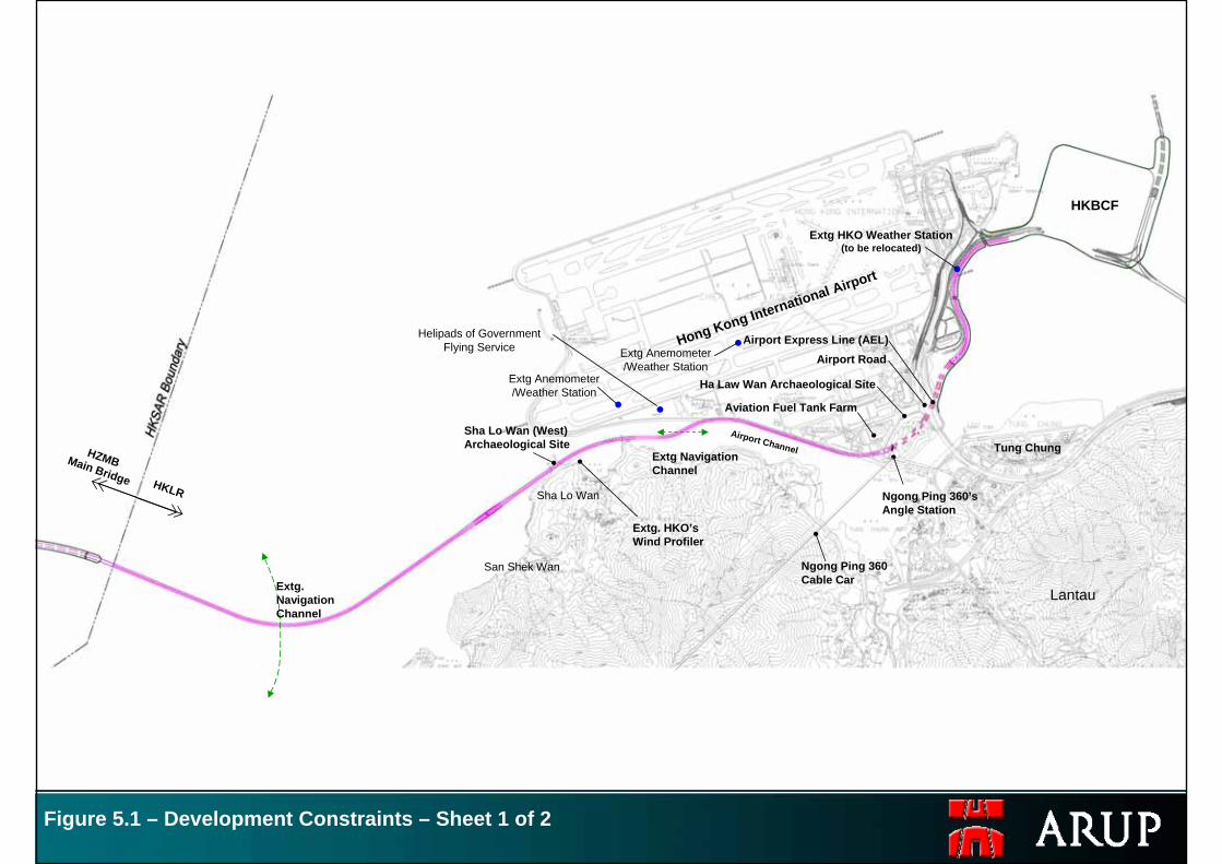
Figure 5.1 – Development Constraints – Sheet 1 of 2
HKBCF
HZMBMain Bridge HKLR
Hong Kong International Airport
Tung Chung
Ngong Ping 360’sAngle Station
Ngong Ping 360Cable Car
Sha Lo Wan (West)Archaeological Site
Ha Law Wan Archaeological Site
Airport Express Line (AEL)Airport Road
Extg HKO Weather Station(to be relocated)
Airport Channel
Aviation Fuel Tank Farm
Lantau
San Shek Wan
Sha Lo Wan
Extg.Navigation Channel
Extg Navigation Channel
Extg. HKO’sWind Profiler
Extg Anemometer /Weather Station
Extg Anemometer /Weather Station
Helipads of Government Flying Service
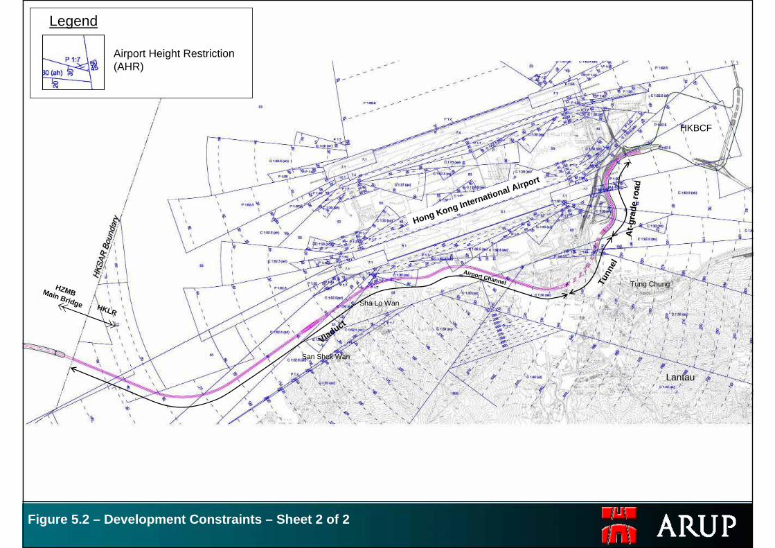
Figure 5.2 – Development Constraints – Sheet 2 of 2
Legend
Airport Height Restriction (AHR)
HKBCF
Tung Chung
Lantau
San Shek Wan
Sha Lo Wan
HZMBMain Bridge HKLR
Airport Channel
Hong Kong International Airport
Viaduct
Tunn
el
At-g
rade
road
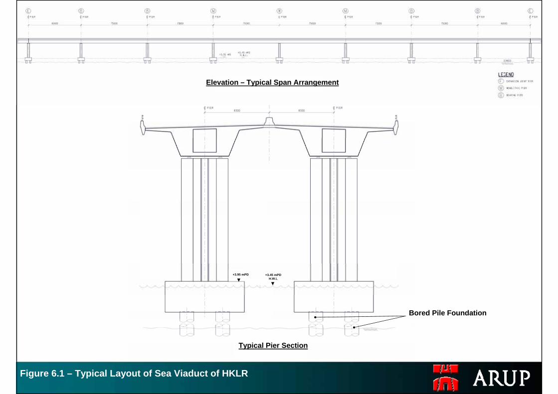
Figure 6.1 – Typical Layout of Sea Viaduct of HKLR
Bored Pile Foundation
+3.45 mPDH.W.L
+3.95 mPD
Typical Pier Section
Elevation – Typical Span Arrangement
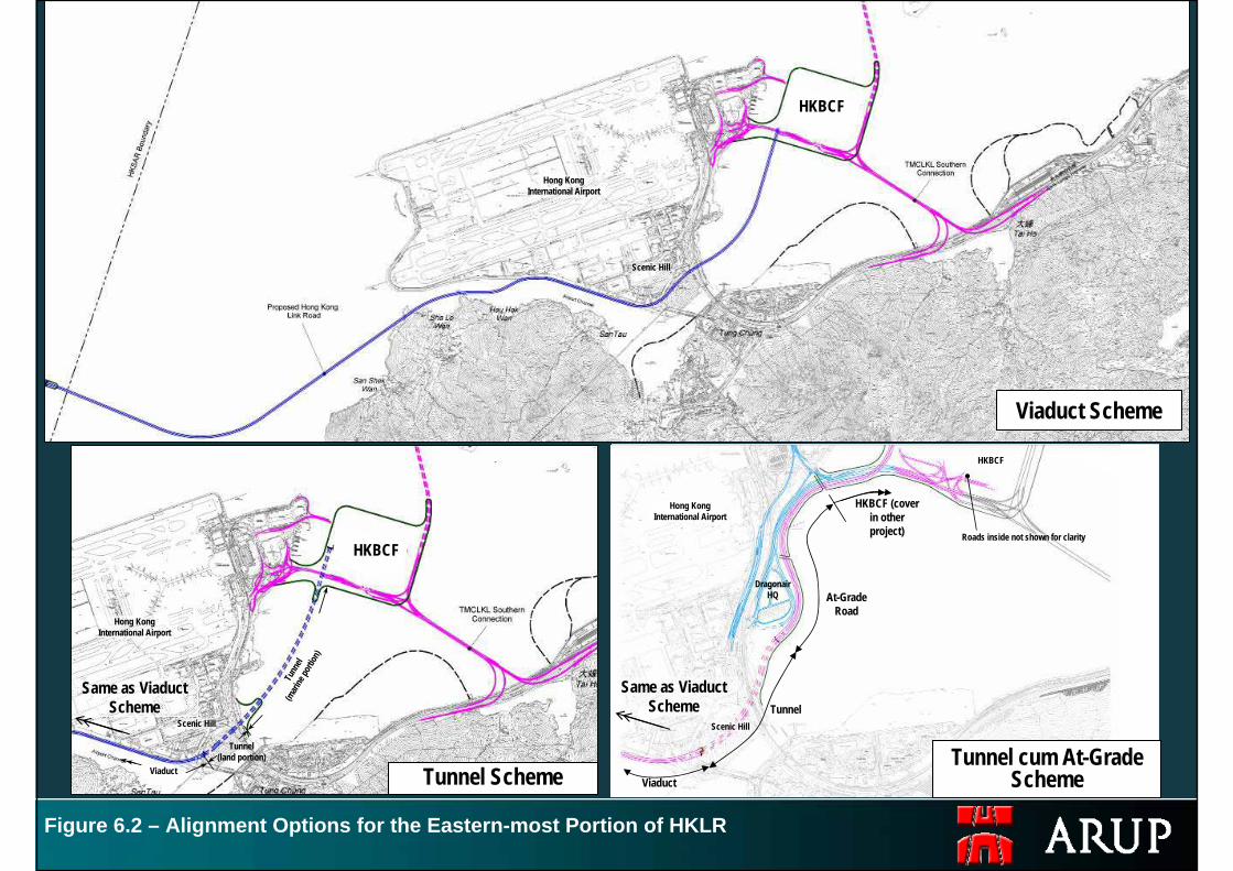
Figure 6.2 – Alignment Options for the Eastern-most Portion of HKLR
Viaduct Scheme
Tunnel Scheme
Scenic Hill
Scenic Hill Scenic Hill
Hong Kong International Airport
Hong Kong International Airport
Hong Kong International Airport
Same as Viaduct Scheme
Same as Viaduct Scheme
Roads inside not shown for clarity
ViaductViaduct
Tunn
el(m
arine
portio
n)
HKBCF
Tunnel cum At-Grade Scheme
Tunnel
At-Grade Road
HKBCF (cover in other project)
DragonairHQ
HKBCF
HKBCF
Tunnel(land portion)
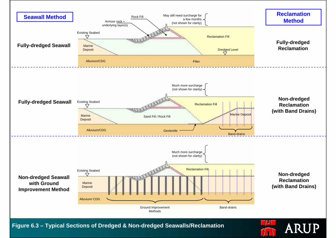
Figure 6.3 – Typical Sections of Dredged & Non-dredged Seawalls/Reclamation
Surcharge same as (B)
Marine Deposit
Alluvium/ CDG
Reclamation Fill
Ground Improvement Methods
Filter
Armour rock + underlying layer(s)
Rock Fill May still need surcharge for a few months
(not shown for clarity)
Marine Deposit
Alluvium/CDG
Reclamation Fill
Sand Fill/Rock Fill Dredged Level
Much more surcharge (not shown for clarity)
Marine Deposit
Alluvium/CDG
Reclamation Fill
Sand Fill/Rock Fill
Band-drainsGeotextile
Marine Deposit
Band-drains
Existing Seabed
Existing Seabed
Existing Seabed
Seawall Method Reclamation Method
Fully-dredged Seawall
Non-dredged Seawall with Ground
Improvement Method
Fully-dredged Seawall
Non-dredged Reclamation
(with Band Drains)
Fully-dredged Reclamation
Existing Seabed
Existing Seabed
Band-drainsGround Improvement Methods
Much more surcharge (not shown for clarity)
Sand Fill / Rock Fill
Non-dredged Reclamation
(with Band Drains)
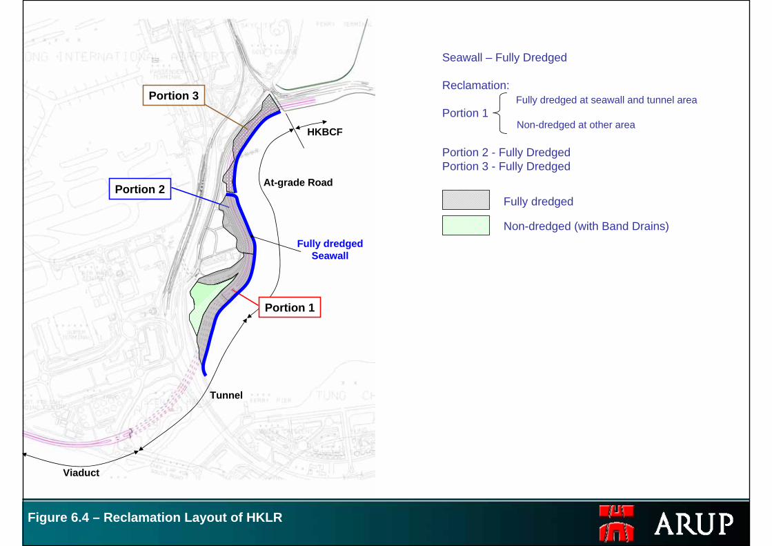
Figure 6.4 – Reclamation Layout of HKLR
Non-dredged (with Band Drains)
Fully dredged
Seawall – Fully Dredged
Reclamation:
Portion 1Portion 3
Portion 2
Fully dredged Seawall
Viaduct
Portion 1
Tunnel
At-grade Road
HKBCF
Fully dredged at seawall and tunnel area
Portion 2 - Fully DredgedPortion 3 - Fully Dredged
Non-dredged at other area
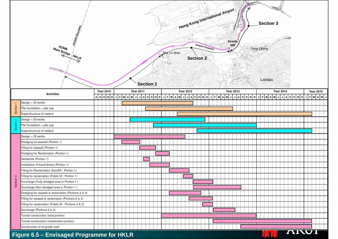
Figure 6.5 – Envisaged Programme for HKLR
HZMBMain Bridge HKLR
Tung Chung
Lantau
Sha Lo Wan
Scenic HillAirport Channel
Hong Kong International Airport
Section 1
Section 2
Section 3