Embed Size (px)
Citation preview

PORTABLE MAGNETIC DRILL
OPERATOR’S MANUAL
FOR USE WITH “12,000-SERIES” HOUGEN® CUTTERS
HMD904
2
HOUGEN®
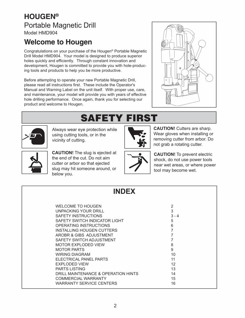
Portable Magnetic DrillModel HMD904
Welcome to HougenCongratulations on your purchase of the Hougen® Portable Magnetic
Drill Model HMD904. Your model is designed to produce superior
holes quickly and efficiently. Through constant innovation and
development, Hougen is committed to provide you with hole-produc-
ing tools and products to help you be more productive.
Before attempting to operate your new Portable Magnetic Drill,
please read all instructions first. These include the Operator's
Manual and Warning Label on the unit itself. With proper use, care,
and maintenance, your model will provide you with years of effective
hole drilling performance. Once again, thank you for selecting our
product and welcome to Hougen.
Always wear eye protection while
using cutting tools, or in the
vicinity of cutting.
CAUTION! The slug is ejected at
the end of the cut. Do not aim
cutter or arbor so that ejected
slug may hit someone around, or
below you.
CAUTION! Cutters are sharp.
Wear gloves when installing or
removing cutter from arbor. Do
not grab a rotating cutter.
CAUTION! To prevent electric
shock, do not use power tools
near wet areas, or where power
tool may become wet.
SAFETY FIRST
INDEX
WELCOME TO HOUGEN 2
UNPACKING YOUR DRILL 3
SAFETY INSTRUCTIONS 3 - 4
SAFETY SWITCH INDICATOR LIGHT 5
OPERATING INSTRUCTIONS 6
INSTALLING HOUGEN CUTTERS 7
AROBR & GIBS ADJUSTMENT 7
SAFETY SWITCH ADJUSTMENT 7
MOTOR EXPLODED VIEW 8
MOTOR PARTS 9
WIRING DIAGRAM 10
ELECTRICAL PANEL PARTS 11
EXPLODED VIEW 12
PARTS LISTING 13
DRILL MAINTENANCE & OPERATION HINTS 14
COMMERCIAL WARRANTY 15
WARRANTY SERVICE CENTERS 16

UNPACKING YOUR NEW MAGNETIC DRILL
1. Open shipping carton and remove the literature and
hardware packages.
2. Read and Follow All Instructions before attempting
to operate your new Magnetic Drill.
3. Complete and mail the Product Registration Card now.
It is important that Hougen Manufacturing, Inc. have a
record of product ownership.
4. Open hardware package and check contents.
10565 1/8" Hex wrench for Gib Adjustment
04558 Feed handles (3)
04532 Feed handle knobs (3)
10506 Set screw for cutter installation (2)
10730 Safety chain
02635 Hex wrench for cutter installation
13013 5/32" Hex wrench for safety switch adjustment
5. Using the handle of Magnetic Drill, lift unit out of the
shipping case.
6. Remove all packing and securing material from the drill
unit.
7. Screw the three Knobs (04532) into the three
Feed Handles (04558) and then screw Handles
into the Hub Assembly (40254). Do not overtighten
or may strip the knobs.
8. Your Magnetic Drill was factory adjusted prior to
shipping. Check to make sure that all gib
adjustment screws, motor mount screws, front
support bracket screws, and magnet mounting
screws are snug and have not vibrated loose in
transit.
9. Your new Magnetic Drill comes complete with
arbor mounted. The 3/4" diameter arbor bore
fits all 3/4"-shank "12,000-Series" Hougen
Cutters. A 1/2" diameter bore Arbor Adapter
(10851), for mounting 1/2" shank "12,000-Series"
Hougen Cutters, is optional.
Reread Safety Warnings listed in the Operator's
Manual and on the drill unit to avoid injury. Follow
operating procedures.
IMPORTANT SAFETY INSTRUCTIONSWARNING: When using electric tools, basic safety precautions should always be followed to reduce the risk of fire, electric
shock, and personal injury, including the following:
1. Read All Instructions
2. Grounding Instructions
This tool should be grounded while in use to protect the operator from electric shock. The tool is equipped
with a 3-conductor cord and a 3-prong grounding type lug to fit the proper grounding type receptacle. The
green (or green and yellow) conductor in the cord is the grounding wire. Never connect the green (or green and
yellow) wire to a live terminal. If your unit is for use on 115V, it has a plug that looks like that shown in
sketch (A). If it is for use on 230V, it has a plug that looks like that shown in sketch (D). An adapter, see
sketches (B) and (C), is available for connecting 115V type plugs to 2-prong receptacles. The green-colored
rigid ear, lug, or the like, extending from the adapter must be connected to a permanent ground, such as a
properly grounded outlet box. (See Table 2, Page 5)
3
3. Extension Cords
Use only 3-wire extension cords that have 3-prong grounding type plugs and 3-pole receptacles that accept the
tool's plug. Replace or repair damaged cords. Make sure the conductor size is large enough to prevent
excessive voltage drop which will cause loss of power and possible motor damage. (See Table 1)
4. Consider Work Area Environment
Do not expose tool to rain. Do not use tool in damp or wet locations. Keep work area well lit. Do not use tool in
presence of flammable liquids or gases.
5. Guard Against Electric Shock
Prevent body contact with grounded surfaces. For example: pipes, radiators, ranges, refrigerator enclosures.
6. Safety Chains
For Operator safety -Always use the provided safety chain every time you use the unit. Failure to use the safety
chain can result in serious personal injury plus possible damage to your machine.
10. Secure Work
Use clamps or a vise to hold work. It is safer than using your hand and it frees both hands to operate tool.
7. Keep Children Away
Do not let visitors contact tool. All visitors should be kept away from work area.
8. Store Idle Tools
When not in use, tools should be stored in a dry, land high or locked-up place — out of reach of children.
9. Use Right Tool
Do not force small tool or attachment to do the job of a heavy duty tool. Do not use tool for purpose not intended
— for example — do not use a circular saw for cutting tree limbs or logs.

15. Maintain Tools With Care
Keep tools sharp and clean for better and safer performance. Do not use dull or broken Hougen Cutters.
Follow instructions for lubricating and changing accessories. Inspect tool cords periodically and, if damaged,
have repaired by authorized service facility. Inspect extension cords periodically and, if damaged, have repaired
by authorized service facility. Keep handles dry, clean, and free from oil and grease.
16. Disconnect Tools
When not in use, before servicing, and when changing Hougen Cutters or accessories.
17. Remove Adjusting Keys and Wrenches
Form a habit of checking to see that keys and wrenches are removed from tool before turning it on.
4
11. Always Wear Safety Glasses or Goggles
12. Dress Properly
Do not wear loose clothing or jewelry. They might entangle with spinning chips or get caught in moving parts.
Rubber gloves and nonskid footwear are recommended when working outdoors. Wear sturdy leather gloves
when working indoors. Wear protective hair covering to contain long hair.
13. Do Not Abuse Cord
Never carry drill unit by its cord or yank it to disconnect from receptacle. Keep cord away from heat, oil, and
sharp edges.
14. Do Not Overreach
Keep proper footing and balance at all time.
18. Check Damaged Parts
Before further use of the drill, a part that is damaged should be carefully checked to determine that it will operate
properly and perform its intended function. Check for alignment of moving parts, binding of moving parts,
breakage of parts, mounting, and any other conditions that may affect its operation. A part that is damaged
should be properly repaired or replaced by an authorized service center unless otherwise indicated elsewhere
in this operator manual. Do not operate tool if switch does not turn it on and off.
19. Stay Alert
Watch what you are doing. Use common sense. Do not operate tool when you are tired. Have defective
switches replaced by authorized service center.
20. Outdoor Use Extension Cords
When tool is used outdoors, use only extension cords intended for use outdoors and so marked. Refer to
Table 1 for recommended extension cord gauge.21. Additional Safety Precautions
Arbor and cutter should never be used as a hand hold. Keep hands and clothing away from all moving parts.
Do not use Hougen Cutters where ejected slug might cause injury (slug ejected at end of cut). Be sure
that all safety devices are properly adjusted and in use. Also, adhere to all operating instructions. Do
not drill through any surface that may contain live electrical wiring. Drilling into a live wire could cause
exposed metal parts of the drill to be made live. Remove chips wrapped around Hougen Cutter and
arbor after each hole. With motor off and power disconnected, grasp chips with leather gloved hand or
pliers and pull while rotating counterclockwise. Should the cutter become jammed in the work, stop the unit
immediately to prevent personal injury. Disconnect the drill from the power supply and loosen jammed cutter
by turning the arbor counterclockwise. Never attempt to free the jammed cutter by starting the motor. If service
is required contact your nearest authorized service center.
22. Non-Conforming Cutting Tools
Your Magnetic Drill is designed to use Hougen Cutters. The use of drilling tools having different shank
styles is not recommended as they may not tighten securely in the drill arbor with risk of accident or
injury.
IMPORTANT SAFETY INSTRUCTIONS (CONT)
23. Operating Near Welding Equipment
It is not recommended to operate your magnetic drill near or around a welder while
welding is being performed. Damage to your drill could result.
24. Safe Electrical Connection
Wet electrical connections are shock hazards. To prevent the cutting fluid from traveling
along the cord and contacting the plug or power outlet, tie a drip loop as shown. Also
elevate extension cords or gang box connections.
25. Save These Instructions

TABLE 1
5
TABLE 2
,droCfohtgneL
teeF
dednemmoceR
eguaGeriW
dednemmoceR
eguaGeriW
rotoMV511
spmA21-01
rotoMV032
spmA6-4
52otpU 61 81
05-62 41 81
001-15 01 61
002-101 8 41
003-102 6 21
005-103 4 01
SAFETY SWITCH INDICATOR LIGHT
The Safety Switch Indicator Light is a New Standard Safety Feature on HMD904 magnetic drills. Its
purpose is to inform the user that an unsafe condition exists or the safety switch needs adjusting.
If light is Green:
In normal operation the safety switch light will be green.
Motor “On” and “Off” Switches function normally.
If light is Red:
A condition with the safety switch exists that needs to be corrected.
Possible causes:
• Safety Switch is out of adjustment (See Page 7).
• Safety Switch is defective. Have drill serviced.
• Uneven work surface or material. Check work surface for
flatness.
• Dirt or chips under magnet. Clean work surface.
• Too thin material. Make sure material is at least 3/8” thick.
HOUGEN MANUFACTURING RECOMMENDS THAT
CONDITIONS ARE CORRECTED SO LIGHT TURNS GREEN.
THIS ALLOWS FOR THE UNIT TO BE OPERATED IN A SAFE
MANNER.
When light is Red the motor will still function, but “ON” switch
becomes a momentary switch. (The switch must be held down to
operate motor.)
For any questions please contact Hougen Manufacturing’s Technical
Service at (810) 635-7111.
OPERATING INSTRUCTIONS
Always remember that the magnet's holding power is directly related to the workpiece thickness and surface
condition. Since magnetic attraction diminishes with thinner material or rough surfaces, mechanical clamping of drill
unit to the workpiece should be used when cutting thin material (3/8” or less) or material with uneven surfaces.
1. Make sure workpiece and bottom of magnet are free of chips, oil, etc.
2. Position drill by sliding it and gently feeding Arbor so that pilot point is touching center of hole to be drilled.
3. Secure unit to workpiece with safety chain.
4. Turn magnet ON by pressing the magnet ON button.
5. Turn Feed Handle, raising the cutter until the pilot is above the work surface.
6. Make certain that cutter is clear of workpiece and turn motor ON by pressing the motor START button.
7. Feed Hougen Cutter slowly into workpiece. Only after cutting path is established to a depth of about 1/16"
can full force be applied to feed handles.
8. Ease up on feed pressure as cutter starts breaking through.
9. At conclusion of cut, turn motor OFF by pressing motor STOP button. Turn Feed Handles to raise Arbor
thereby ejecting the slug if it hasn't already fallen free.
10. Turn magnet OFF by pressing the magnet OFF button. As the magnet de-energizes, the rear of the magnet
should lift up off the work surface.
11. Disconnect from power source.
12. If necessary, remove chips from cutter and magnet, preferably wearing leather work gloves and/or with pliers.
Disconnect safety chain and you are ready to move unit to new drilling position.
6
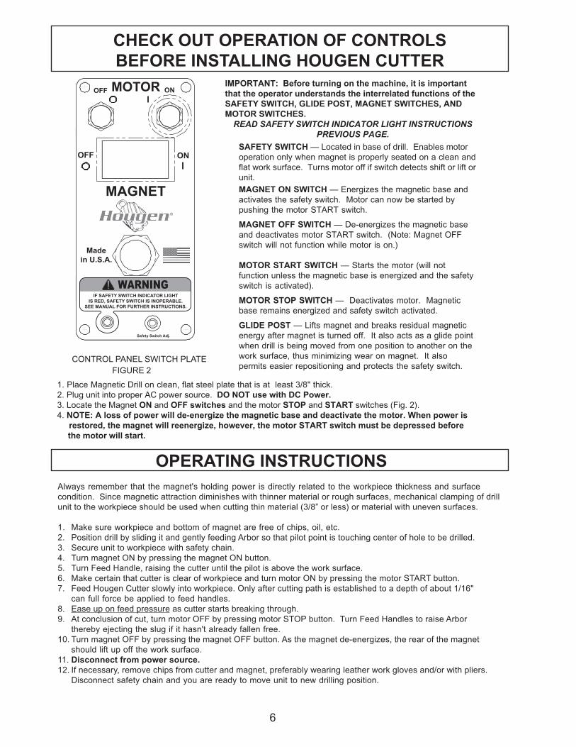
CHECK OUT OPERATION OF CONTROLS
BEFORE INSTALLING HOUGEN CUTTERIMPORTANT: Before turning on the machine, it is important
that the operator understands the interrelated functions of the
SAFETY SWITCH, GLIDE POST, MAGNET SWITCHES, AND
MOTOR SWITCHES.
READ SAFETY SWITCH INDICATOR LIGHT INSTRUCTIONS
PREVIOUS PAGE.
SAFETY SWITCH — Located in base of drill. Enables motor
operation only when magnet is properly seated on a clean and
flat work surface. Turns motor off if switch detects shift or lift or
unit.
MAGNET ON SWITCH — Energizes the magnetic base and
activates the safety switch. Motor can now be started by
pushing the motor START switch.
MAGNET OFF SWITCH — De-energizes the magnetic base
and deactivates motor START switch. (Note: Magnet OFF
switch will not function while motor is on.)
MOTOR START SWITCH — Starts the motor (will not
function unless the magnetic base is energized and the safety
switch is activated).
MOTOR STOP SWITCH — Deactivates motor. Magnetic
base remains energized and safety switch activated.
GLIDE POST — Lifts magnet and breaks residual magnetic
energy after magnet is turned off. It also acts as a glide point
when drill is being moved from one position to another on the
work surface, thus minimizing wear on magnet. It also
permits easier repositioning and protects the safety switch. CONTROL PANEL SWITCH PLATE
FIGURE 2
1. Place Magnetic Drill on clean, flat steel plate that is at least 3/8" thick.
2. Plug unit into proper AC power source. DO NOT use with DC Power.
3. Locate the Magnet ON and OFF switches and the motor STOP and START switches (Fig. 2).
4. NOTE: A loss of power will de-energize the magnetic base and deactivate the motor. When power is
restored, the magnet will reenergize, however, the motor START switch must be depressed before
the motor will start.
IF SAFETY SWITCH INDICATOR LIGHT
IS RED, SAFETY SWITCH IS INOPERABLE.
SEE MANUAL FOR FURTHER INSTRUCTIONS.
MOTOR
OFF ON
MAGNET
OFF ON
Made
in U.S.A.
Safety Switch Adj.
WARNING
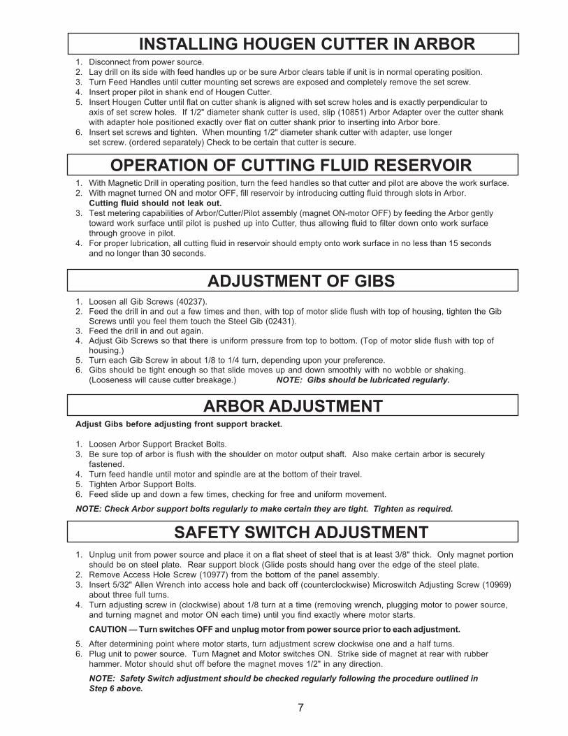
INSTALLING HOUGEN CUTTER IN ARBOR1. Disconnect from power source.
2. Lay drill on its side with feed handles up or be sure Arbor clears table if unit is in normal operating position.
3. Turn Feed Handles until cutter mounting set screws are exposed and completely remove the set screw.
4. Insert proper pilot in shank end of Hougen Cutter.
5. Insert Hougen Cutter until flat on cutter shank is aligned with set screw holes and is exactly perpendicular to
axis of set screw holes. If 1/2" diameter shank cutter is used, slip (10851) Arbor Adapter over the cutter shank
with adapter hole positioned exactly over flat on cutter shank prior to inserting into Arbor bore.
6. Insert set screws and tighten. When mounting 1/2" diameter shank cutter with adapter, use longer
set screw. (ordered separately) Check to be certain that cutter is secure.
7
ADJUSTMENT OF GIBS1. Loosen all Gib Screws (40237).2. Feed the drill in and out a few times and then, with top of motor slide flush with top of housing, tighten the Gib
Screws until you feel them touch the Steel Gib (02431).3. Feed the drill in and out again.4. Adjust Gib Screws so that there is uniform pressure from top to bottom. (Top of motor slide flush with top of
housing.)5. Turn each Gib Screw in about 1/8 to 1/4 turn, depending upon your preference.6. Gibs should be tight enough so that slide moves up and down smoothly with no wobble or shaking.
(Looseness will cause cutter breakage.) NOTE: Gibs should be lubricated regularly.
OPERATION OF CUTTING FLUID RESERVOIR1. With Magnetic Drill in operating position, turn the feed handles so that cutter and pilot are above the work surface.
2. With magnet turned ON and motor OFF, fill reservoir by introducing cutting fluid through slots in Arbor.
Cutting fluid should not leak out.
3. Test metering capabilities of Arbor/Cutter/Pilot assembly (magnet ON-motor OFF) by feeding the Arbor gently
toward work surface until pilot is pushed up into Cutter, thus allowing fluid to filter down onto work surface
through groove in pilot.
4. For proper lubrication, all cutting fluid in reservoir should empty onto work surface in no less than 15 seconds
and no longer than 30 seconds.
Adjust Gibs before adjusting front support bracket.
1. Loosen Arbor Support Bracket Bolts.
3. Be sure top of arbor is flush with the shoulder on motor output shaft. Also make certain arbor is securely
fastened.
4. Turn feed handle until motor and spindle are at the bottom of their travel.
5. Tighten Arbor Support Bolts.
6. Feed slide up and down a few times, checking for free and uniform movement.
NOTE: Check Arbor support bolts regularly to make certain they are tight. Tighten as required.
SAFETY SWITCH ADJUSTMENT1. Unplug unit from power source and place it on a flat sheet of steel that is at least 3/8" thick. Only magnet portion
should be on steel plate. Rear support block (Glide posts should hang over the edge of the steel plate.
2. Remove Access Hole Screw (10977) from the bottom of the panel assembly.
3. Insert 5/32" Allen Wrench into access hole and back off (counterclockwise) Microswitch Adjusting Screw (10969)
about three full turns.
4. Turn adjusting screw in (clockwise) about 1/8 turn at a time (removing wrench, plugging motor to power source,
and turning magnet and motor ON each time) until you find exactly where motor starts.
CAUTION — Turn switches OFF and unplug motor from power source prior to each adjustment.
5. After determining point where motor starts, turn adjustment screw clockwise one and a half turns.
6. Plug unit to power source. Turn Magnet and Motor switches ON. Strike side of magnet at rear with rubber
hammer. Motor should shut off before the magnet moves 1/2" in any direction.
NOTE: Safety Switch adjustment should be checked regularly following the procedure outlined in
Step 6 above.
ARBOR ADJUSTMENT
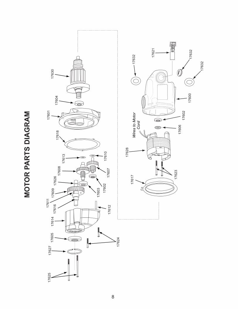
MO
TO
R P
AR
TS
DIA
GR
AM
8
17617
17601
17618
17613
17608
17626
17609
17611
17616
17614
17605
17627
17625
Wires to M
oto
r
Cord
17610
17603
17602
17607
17624
17623
17628
17606
17602
17632
17632
17621
17630
17604
17612
17632
17
60
0

9
04503 MOTOR ASSEMBLY
11053 BOLT TORQUE SPECIFICATIONS - TIGHTEN TO 18 IN-LBS
75289 BOLT TORQUE SPECIFICATIONS - TIGHTEN TO 25 IN-LBS
11053
10538
02413
75289
04502
0452704528 (OPPOSITE SIDE)
MOTOR PARTS LIST
TRAP.ON
NOITPIRCSED.YTQ.D'QER
TRAP.ON
NOITPIRCSED.YTQ.D'QER
30540 .CALPER.YSSAROTOM 11671 YEK 1
72540 .SCEPSROTOM,LEBAL 1 21671 NIPLEWOD 1
82540 409DMHROTOM,LEBAL 1 31671 REHSAWTALF 1
31420 .YSSADROCROTOM 1 41671 GNISUOHRAEG 1
35011 23-8#SHB,WERCS 1 61671 ELDNIPS 1
83501 .TXE8#REHSAW 1 71671 EDIUGNAF 1
20540 REVOCHSURB 1 81671 TEKSAG 1
98257 WERCSDAEHNAP 2 03671 ERUTAMRA 1
00671 ESACDLEIF 1 82671 DLEIF 1
10671 REVOCGNISUOHRAEG 1 12671 HSURBNOBRAC 2
20671 GNIRAEBLLAB 2 22671 PACHSURB 2
30671 GNIRAEBLLAB 1 32671 DLEIF-.RCSDAEHNAP 2
40671 GNIRAEBLLAB 1 42671 TROHS-.RCSDAEHNAP 2
50671 GNIRAEBLLAB 1 52671 GNOL-.RCSDAEHNAP 2
60671 LAESTSUD 1 62671 GNIRGNINIATER 1
70671 YSSARAEGRETNI.TS1 1 72671 GNIRGNINIATER 1
80671 YSSARAEGRETNI.DN2 1 23671 REHSAWREPAP 2
90671 RAEGRUPS 1
01671 REHSAWTALF 1
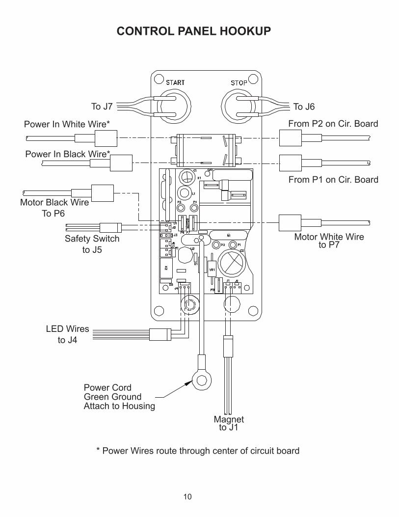
CONTROL PANEL HOOKUP
10
Safety Switch
to J5
Motor Black Wire
To P6
Power CordGreen GroundAttach to Housing
Magnetto J1
Motor White Wireto P7
Power In White Wire*
* Power Wires route through center of circuit board
To J6To J7
LED Wires
to J4
Power In Black Wire*
From P1 on Cir. Board
From P2 on Cir. Board
~
NOTE: WHEN INSERTING L.E.D. INTO HARNESS
MAKE SURE RED ANODE FROM
L.E.D. LINES UP WITH WHITE WIRE ON HARNESS.
WHITE WIRE
ON
MAGNET
OFF
OFFMOTOR
ON
10977
01226
02409
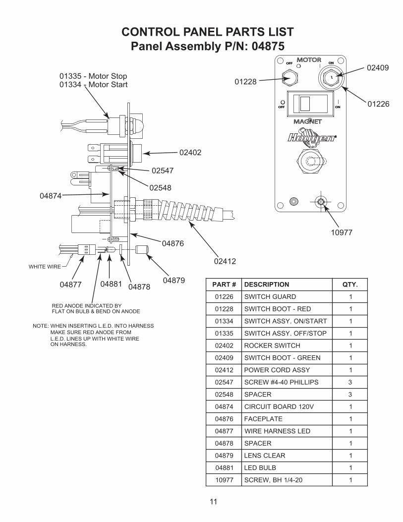
RED ANODE INDICATED BYFLAT ON BULB & BEND ON ANODE
02412
04879
04876
048780488104877
01335 - Motor Stop01334 - Motor Start 01228
02402
02547
0254804874
CONTROL PANEL PARTS LIST
Panel Assembly P/N: 04875
11
#TRAP NOITPIRCSED .YTQ
62210 DRAUGHCTIWS 1
82210 DER-TOOBHCTIWS 1
43310 TRATS/NO.YSSAHCTIWS 1
53310 POTS/FFO.YSSAHCTIWS 1
20420 HCTIWSREKCOR 1
90420 NEERG-TOOBHCTIWS 1
21420 YSSADROCREWOP 1
74520 SPILLIHP04-4#WERCS 3
84520 RECAPS 3
47840 V021DRAOBTIUCRIC 1
67840 ETALPECAF 1
77840 DELSSENRAHERIW 1
87840 RECAPS 1
97840 RAELCSNEL 1
18840 BLUBDEL 1
77901 02-4/1HB,WERCS 1
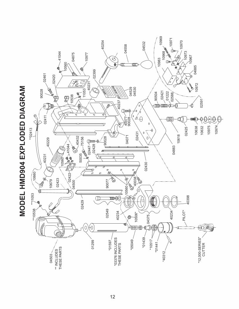
12
M
OD
EL
HM
D904 E
XP
LO
DE
D D
IAG
RA
M
*03376 IN
CLU
DE
S
TH
ES
E P
AR
TS
04883
10618
04529
04530
*01597
*05049
*01439
*10517
*01441
*40312
"12,0
00-S
ER
IES
"
C
UT
TE
R
PIL
OT
*
40234
04375
10506*
40234
025490
2429
**10538
**11053
10660
10679
02423
02422
04500
90077
10560
40038
02430
02425
10638
10632
10975
10974
02591
10972
04885
10967
10973
10970
10971
10969
10983 10968
90504
02421
01222
02588
04071
02431
40077
90028
40237
90028
02428
024477
5156
50035
40432
41044
10560
40229
40231
**02413
01299
02411
90028
02461
02420
10560
41044
10538 11053 40231
02399
10977
40254
04558
04532
40398
** IN
CLU
DE
S
TH
ES
E P
AR
TS
04503
04875

HMD904 PARTS LIST W / ASSEMBLIES
TRAP.ON
NOITPIRCSED.YTQ.D'QER
TRAP.ON
NOITPIRCSED.YTQ.D'QER
99210 TSURHT,REHSAW 1 35011 23-8#CHB,WERCS 1
11420 DROC.RTM-FEILERNIARTS 1 83004 23-01#CHS,WERCS 2
31420 YLBMESSADROCROTOM 1 77004 02-4/1CHS,WERCS 1
02420 PMALCDROCROTOM 2 41204 23-6#CHS,WERCS 1
12420 GNIRPSTSOPEDILG 2 43204 REHSAWTSURHT 2
22420 TEKCARBDROCROTOM 1 45204 YLBMESSABUH 1
32420 .ETORPXELFDROCROTOM 1 89304 GNIRGNINIATER 1
52420 YDOBREGNULP 1 23404 82-4/1CHS,WERCS 1
82420 RAEGKCAR 1 44014 23-01#CHB,WERCS 6
92420 THGIR-BIGSSARB 1 53005 TXE4/1REHSAWKCOL 4
03420 TFEL-BIGSSARB 1 82009 ILEH4/1REHSAWKCOL 5
13420 BIGLEETS 1 25009 .TXE6#REHSAWKCOL 1
74420 82-4/1DAEHXEH-TLOB 2 77009 2/1X23-01#CHBWERCS 1
16420 WERCSCHB8/3X02-4/1 2
19520 GNIRGNINIATER 2 SEILBMESSA
67330 YSSAROBRA 1 14540 YLBMESSAGNISUOH
57340 .YSSA.TKRB.PPUSTNORF 1 13204 GNIHSUBEZNORB 2
00540 TNUOMROTOM,EDILS 1 92204 RAEGDEEF 1
23540 BONKELDNAHDEEF 3 92540 YTEFAS,LEBAL 1
85540 ELDNAHDEEF 3 03540 GNINRAW,LEBAL 2
38840 V511-TENGAM 1 35540 NIAHCGNINRAW,LEBAL 1
58840 .YSSAHCTIWSYTEFAS 1 73204 SWERCSBIG 5
83501 REHSAWKCOL 1 67330 YLBMESSAROBRA
06501 .TXE01#REHSAWKCOL 11 79510 YDOBROBRA 1
81601 GNIRPS.PMOCS/S 1 93410 GNIRPS-TAES 1
23601 GNIRGNINIATER 1 71501 GNIRGNINIATER 2
83601 YSSA.GRBHCTIWSYTEFAS 1 94050 GNIRPSROBRA 1
06601 8/5X02-4/1CHSWERCS 1 14410 RALLOCROTCEJE 1
97601 REHSAWTALF"4/1 1 21304 DERETLANIPLLOR 1
86901 GNIRPSTSUJDAS/S 1 60501 LPS42-8/3TES-RCS 2
96901 WERCSTSUJDAS/S 1 29520 )2(YLBMESSATSOPEDILG
07901 .TKRBTSUJDAS/S 1 88520 TSOPEDILGYDOB 2
17901 02-4/1CHSWERCS 2 22210 REGNULP-ESON 2
27901 23-6#CHBWERCS 2 12420 GNIRPS 2
37901 NOLYNHTIWTUN 2 40509 02-61/7TESCOS-RCS 2
47901 GNIRGNINIATER 1 94520 YLBMESSATIKTLOB
57901 YLBMESSALAESS/S 1 06420 4/32X42-8/3XEHTLOB 2
77901 02-4/1CHB,WERCS 1 19304 ILEH8/3REHSAWKCOL 2
38901 DLEIHSS/S 1 29304 8/3TALFREHSAW 2
57840 YSSALENAPLORTNOC
30540 .CALPER.YSSAROTOM
13

MAINTENANCE
In order to minimize wear on moving parts and to insure smoother operation and longer life for your magnetic drill,
the following maintenance should be done periodically, based on use.
1. Regularly tighten all fasteners and replace all worn parts.
2. Check motor brushes and replace if worn. (Break in period - 30 minutes at no load speed)
3. Check power cord and cord from panel to motor and, if cracked or frayed, return to an authorized repair center for
replacement.
4. Apply grease to the slide dovetails, brass gibs, and the feed gear rack. For best results use Shell Cyprina-RA or
equivalent.
5. Remove arbor and pack the bearing in the front support bracket with grease. Use Shell Cyprina-RA or equivalent.
HINTS FOR SMOOTHER OPERATION1. Keep insides of Hougen Cutter clear of chips. Chips will interfere with cutting to maximum depth, may impede
the free oil flow and can cause cutter breakage.
2. Keep work, machine, arbor and Hougen Cutter free of chips and dirt.
3. Tighten all bolts and fasteners regularly.
4. We highly recommend using a light viscosity cutting fluid (preferably
Hougen Cutting Fluid - Part No. 11742-4)
5. Occasionally check metering of cutting fluid flow. Lack of cutting fluid may
cause Hougen Cutter to freeze in cut, slug to stick and may result in poor
cutter life.
6. Always start cut with light feed pressure and then increase sufficiently to
achieve maximum cutting rate.
7. Ease off on pressure as cutter begins to break through at the end of the cut.
8. Keep slide dovetails, brass gibs and feed rack lubricated and free of chips and dirt.
9. When slug hangs up in cutter, turn off motor and bring cutter down on a flat surface. This will normally straighten a
cocked slug, allowing it to be ejected.
10. When cutting large diameter or deep holes it may be necessary to stop in the middle of the cut to add cutting
fluid and remove the chips from around the arbor. (When doing this DO NOT raise the cutter out of the hole.
Doing so can allow chips to get under the teeth of the cutter and make it difficult to restart the cut.)
REMEDIES FOR HOLEMAKING PROBLEMS1. Trouble: Magnetic base won’t hold effectively to work.
a. Cause: Chips or dirt under magnet.
Remedy: Clear area of chips and dirt.
b. Cause: Irregular surface on bottom of magnet
or on workpiece.
Remedy: Lightly surface grind the bottom of the
magnet flat and/or file imperfections
flat on the work surface as needed.2. Trouble: Cutter tends to move across surface
of work.
a. Cause: Magnetic base not holding effectively.
Remedy: See causes and remedies under No. 1
above.
b. Cause: Too much feed pressure at start of cut.
Remedy: Light pressure until a groove is cut.
The groove then serves as a stabilizer.
c. Cause: Worn pilot.
Remedy: Replace pilot
3. Trouble: Out of round holes.
a. Cause: Worn arbor support bracket bearing
and or ejector collar.
Remedy: Replace: (only a few thousandths
wear permissible.)
b. Cause: Misaligned support bracket
Remedy: Realign support bracket
4. Trouble: Motor and slide won’t stay in set position
a. Cause: Gibs too loose
Remedy: Adjust gibs
5. Trouble: Erratic or intermittent feed.
a. Cause: Worn or pinion and/or rack.
Remedy: Replace worn parts.6. Trouble: Motor doesn’t run when motor START
button is pushed.
a. Cause: Magnet is not turned on
Remedy: Push magnet ON button.
b. Cause: Magnet on rough or dirty work surface
and safety switch not fully depressed.
Remedy: File work surface flat and clean all
chips and oil from under magnet.
c. Cause: Safety switch out of adjustment
Remedy: Adjust safety switch
d. Cause: No power
Remedy: Check power source and extension
cords.
e. Cause: Worn motor brushes
Remedy: Replace brushes
f. Cause: Faulty motor START switch
Remedy: Return unit to an authorized repair
center to have switch replaced.
NOTE: If you are unable to correct any malfunction
after trying the above, do not attempt to operate the
drill. Return the unit to the factory or authorized
repair center for service.
14
#1 cause of cutter
breakage and
prematurely dull
teeth is too little
feed pressure

15
Hougen Manufacturing, Incorporated warrants its Portable Magnetic Drills and its Electro-hydraulic Hole Punchers for a period
of 1 year and other products for ninety (90) days from date of purchase against defects due to faulty material or workmanship
and will repair or replace (at its option) without charge any items returned. This warranty is void if the item has been damaged
by accident or unreasonable use, neglect, improper service, or other causes not arising out of defects in material or workman
ship. No other expressed warranty is given or authorized. Hougen Manufacturing, Inc. disclaims any implied warranty of
MERCHANTABILITY or FITNESS for any period beyond the expressed warranty and shall not be liable for incidental or
consequential damages. Some states do not allow exclusions of incidental or consequential damages or limitation on how long
an implied warranty lasts and, if the law of such a state governs your purchase, the above exclusion and limitation may not
apply to you. This warranty gives you specific legal rights and you may also have other rights which vary from state to state.
To obtain warranty service, return the item(s), transportation prepaid, to your nearest Factory Authorized Warranty Repair
Center or to Hougen Manufacturing, Inc., 3001 Hougen Drive, Swartz Creek, Michigan 48473.
Hougen Drills are warranted against manufacturing defects only. Subject to Hougen Manufacturing inspection.
THIS WARRANTY IS IN LIEU OF ANY OTHER WARRANTY, EXPRESSED OR IMPLIED, INCLUDING ANY
WARRANTY OF MERCHANTABILITY OR FITNESS FOR A PARTICULAR PURPOSE.
© 2004 Hougen Manufacturing, Inc.
Commercial / Industrial Limited Warranty
Photographs and Specifications shown are accurate in detail at time of printing. Manufacture reserves the right to
make improvements and modifications without prior notice.
Hougen, Rotabroach, and Hougen-Edge are proprietary trademarks of Hougen Manufacturing Inc.