Embed Size (px)
Citation preview

Hobie Twist-n-Stow Rudder System Repair Manual
Overview
Due to the internal (hull) routing of rudder control lines, the rudder control system is likely the most misunderstood feature of a Hobie kayak. Repairing or replacing the rudder control lines is easier with a good understanding of the system, so these instructions will cover both the steering system as well as the up-down system.
Note: Being able to see what you are dealing with inside the hull is very important. The use of a small digital camera, placed into one of the access hatches, can greatly improve your understanding of the system by taking photos of the issue you are trying to correct.
There are two distinct rudder control systems: Steering and Up/Down. Both systems use Spectra* control line which enters the hull through Control Line Tubes.
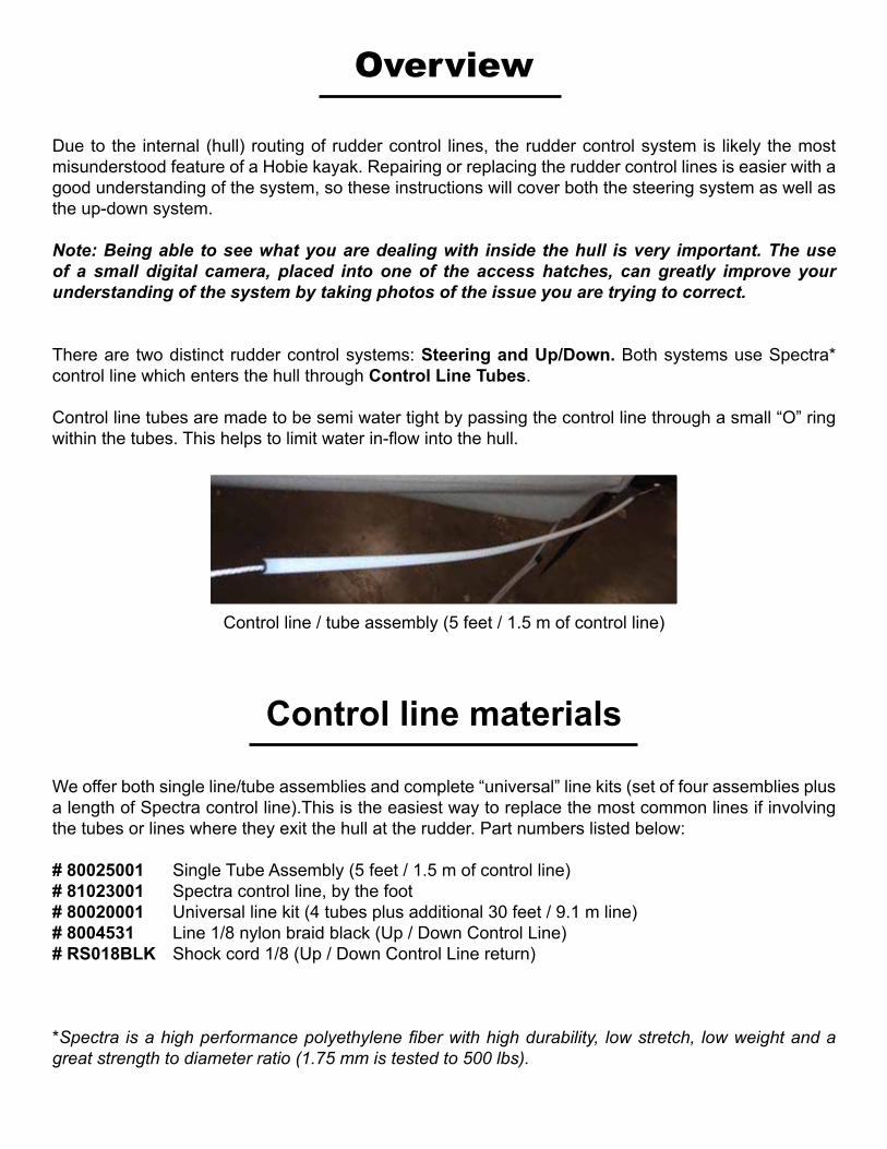
Control line tubes are made to be semi water tight by passing the control line through a small “O” ring within the tubes. This helps to limit water in-flow into the hull.
Control line / tube assembly (5 feet / 1.5 m of control line)
We offer both single line/tube assemblies and complete “universal” line kits (set of four assemblies plus a length of Spectra control line).This is the easiest way to replace the most common lines if involving the tubes or lines where they exit the hull at the rudder. Part numbers listed below:
# 80025001 Single Tube Assembly (5 feet / 1.5 m of control line)# 81023001 Spectra control line, by the foot # 80020001 Universal line kit (4 tubes plus additional 30 feet / 9.1 m line) # 8004531 Line 1/8 nylon braid black (Up / Down Control Line)# RS018BLK Shock cord 1/8 (Up / Down Control Line return)
*Spectra is a high performance polyethylene fiber with high durability, low stretch, low weight and a great strength to diameter ratio (1.75 mm is tested to 500 lbs).
Control line materials
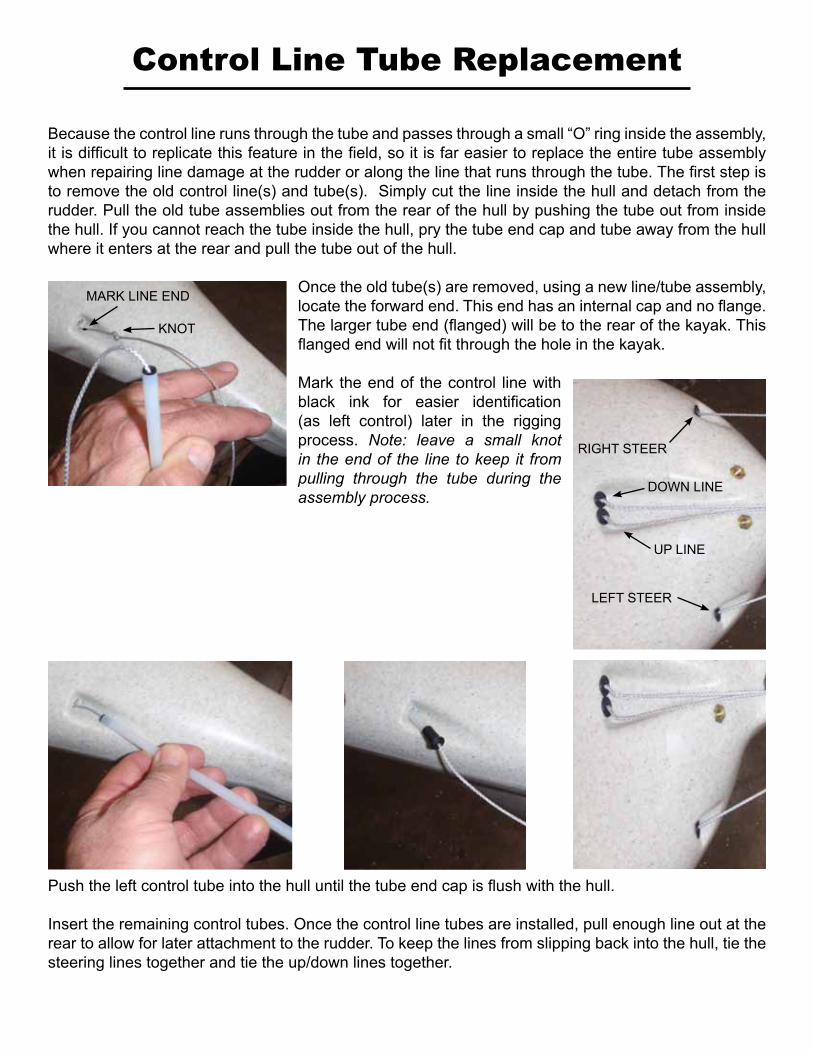
Because the control line runs through the tube and passes through a small “O” ring inside the assembly, it is difficult to replicate this feature in the field, so it is far easier to replace the entire tube assembly when repairing line damage at the rudder or along the line that runs through the tube. The first step is to remove the old control line(s) and tube(s). Simply cut the line inside the hull and detach from the rudder. Pull the old tube assemblies out from the rear of the hull by pushing the tube out from inside the hull. If you cannot reach the tube inside the hull, pry the tube end cap and tube away from the hull where it enters at the rear and pull the tube out of the hull.
Once the old tube(s) are removed, using a new line/tube assembly, locate the forward end. This end has an internal cap and no flange. The larger tube end (flanged) will be to the rear of the kayak. This flanged end will not fit through the hole in the kayak.
Mark the end of the control line with black ink for easier identification (as left control) later in the rigging process. Note: leave a small knot in the end of the line to keep it from pulling through the tube during the assembly process.
Control Line Tube Replacement
Push the left control tube into the hull until the tube end cap is flush with the hull.
Insert the remaining control tubes. Once the control line tubes are installed, pull enough line out at the rear to allow for later attachment to the rudder. To keep the lines from slipping back into the hull, tie the steering lines together and tie the up/down lines together.
MARK LINE END
KNOT
RIGHT STEER
UP LINE
LEFT STEER
DOWN LINE
Steering System
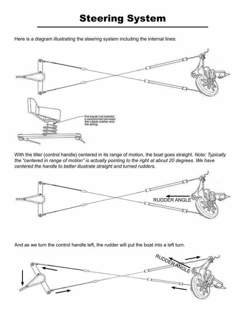
Here is a diagram illustrating the steering system including the internal lines:
And as we turn the control handle left, the rudder will put the boat into a left turn.
RUDDER ANGLE
RUDDER ANGLE
With the tiller (control handle) centered in its range of motion, the boat goes straight. Note: Typically the “centered in range of motion” is actually pointing to the right at about 20 degrees. We have centered the handle to better illustrate straight and turned rudders.

Here’s an image of the stock steering lines attached onto the control arm inside the hull. Note: Control arms are shaped at different angles to conform to the internal shape of the hull. These vary from boat to boat. Notice also that we use loops created with compression swages during production. We will use simple knots to connect replacement lines.
The steering lines need extensions or what we will call “Jumpers” to reach the control arm: Measure from the rudder forward to the steering control handle. The control line tube assembly has 5 feet / 1.5 m of control line. Measure the difference to the handle then allow an additional 1.5 feet of line for knots and loops. Cut 2 lengths of control line for the “jumpers” to reach the control handle.
It is advised to remove the control arm at this time and do all of the line attachments at the rear hatch opening (if included in your model).
Open the aft hatch, pull all 4 of the control lines out of the hatch. Tie loops in the ends of each line as shown. Tie loops in one end of each jumper line. To connect the two steering lines to the jumpers follow the steps below...
UP Control Line
Pass the jumper line loop through the steering line loop
Steering line loop
Jumper line loop
Pass the opposite end of the jumper line through the jumper line loop
Pull the jumper line through the jumper line loop until the loop doubles over on itself
Steering line loop (will be approx. 18” forward of tube end)
Pull tightly to seat the loops onto each other
j
k l
m n
o
Right Steer Line
Left Steer Line

Determine the left and right sides of the control arm. The recess for the steering handle set-screw faces the right side of the control arm. Identify the steering line from the left control line tube (line was marked in black earlier). Remember, the control lines must cross inside the hull to enable the steering handle to swing left and turn the rudder for a left turn.
RUDDER ANGLE
Tie the left steering control line to the right side of the control arm. Tie the line from the right side of the rudder to the left side of the control arm. Note: after re-installing the control handle, we will pull slack out of the rear of the kayak to adjust steering line tension.
There are several options for effective knots at this connection. Simple over hand knots (half hitch) work very well as shown here.
When pulled tight, the knots should stay secure, but a small drop of super glue on the knot will hold even better. You can also use tape, small zip ties or something similar to hold the loose end of the line to prohibit the knots to unraveling.
j k
l

Inside the hull, route the up control and steering controls to the left side of the hull.
Hang the tubes in the eyes as shown.
RUDDER DOWN
RUDDER UP
RIGHT STEER
LEFT STEER
Slide the control arm forward in the hull and remount. It is easier to do if a second person helps hold the arm in place while the steering handle is attached. Check the orientation and that the lines are not tangled... but still cross. Slide the spring on the shaft and press the control arm up through the hull. Instal the steering handle with the set screw.
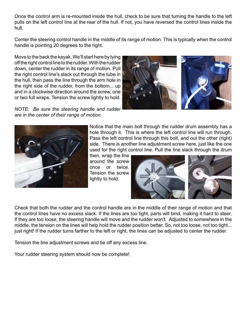
Once the control arm is re-mounted inside the hull, check to be sure that turning the handle to the left pulls on the left control line at the rear of the hull. If not, you have reversed the control lines inside the hull.
Center the steering control handle in the middle of its range of motion. This is typically when the control handle is pointing 20 degrees to the right.
Move to the back the kayak. We’ll start here by tying off the right control line to the rudder. With the rudder down, center the rudder in its range of motion. Pull the right control line’s slack out through the tube in the hull, then pass the line through the arm hole in the right side of the rudder, from the bottom... up and in a clockwise direction around the screw, one or two full wraps. Tension the screw lightly to hold.
NOTE: Be sure the steering handle and rudder are in the center of their range of motion.
Notice that the main bolt through the rudder drum assembly has a hole through it. This is where the left control line will run through. Pass the left control line through this bolt, and out the other (right) side. There is another line adjustment screw here, just like the one used for the right control line. Pull the line slack through the drum then, wrap the line around the screw once or twice. Tension the screw lightly to hold.
Check that both the rudder and the control handle are in the middle of their range of motion and that the control lines have no excess slack. If the lines are too tight, parts will bind, making it hard to steer. If they are too loose, the steering handle will move and the rudder won’t. Adjusted to somewhere in the middle, the tension on the lines will help hold the rudder position better. So, not too loose, not too tight... just right! If the rudder turns farther to the left or right, the lines can be adjusted to center the rudder.
Tension the line adjustment screws and tie off any excess line.
Your rudder steering system should now be complete!

Rudder Up / Down System
First we will take a look at what the up / down control lines do, then how they route inside the hull.
The following diagram shows just the down control line system including the hold-down cleat. The up control is identical, less the cleat. (A few versions used a cleat to hold the rudder up as well)
To lower the rudder, the DOWN “T” handle is pulled. The shock cord is stretched until the slack in the control line goes taut, then the control line pulls through to the rudder drum and that lowers the rudder.
To hold the rudder down, you set the tensioned line into the hold-down cleat.
When you release the “T” handle from the cleat and let it go, the shock cord pulls the line (running to the “T” handle) back into the hull.
To raise the rudder you then pull on the left UP “T” handle until the rudder is on the deck. Then release the “T” handle. The shock cord on the left line system pulls that line back into the hull. (Do not try to raise the rudder if the down line is still cleated)
Both “T” handles should retract right to the deck exit tube locations.
When the “T” handles are released, this leaves some slack line gathered near the aft of the kayak just ahead of the tube. This is normal.
Control line routing:
Starting from the rudder... Spectra control line comes from the rudder drum through the aft tube and then ties onto a 1/8” nylon line. This (black) line is what goes forward, around the turning block and then back out the deck exit tube to the “T” handle. The shock cord is anchored at a location aft of its connection point on the nylon line to pull that line aft.
Hold-down Cleat
“T” Handle
Deck exit tube
TurningBlock
Shock cordand anchor
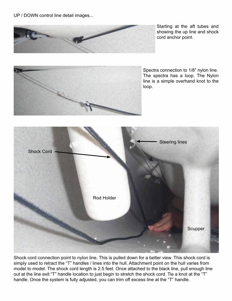
UP / DOWN control line detail images...
Starting at the aft tubes and showing the up line and shock cord anchor point.
Spectra connection to 1/8” nylon line.The spectra has a loop. The Nylon line is a simple overhand knot to the loop.
Shock cord connection point to nylon line. This is pulled down for a better view. This shock cord is simply used to retract the “T” handles / lines into the hull. Attachment point on the hull varies from model to model. The shock cord length is 2.5 feet. Once attached to the black line, pull enough line out at the line exit “T” handle location to just begin to stretch the shock cord. Tie a knot at the “T” handle. Once the system is fully adjusted, you can trim off excess line at the “T” handle.
Scupper
Rod Holder
Shock Cord
Steering lines

UP / DOWN control line detail images...
Nylon line passing around the turningblock up forward
Looking aft... at the deck exit tube
“T” handle outside the hull
The Twist n Stow rudder is designed to rotate from flat on the deck to the down and steering position. This rotation and “twist” is achieved by the up and down control lines. The up and down lines wrap around the drum inside the rudder head. The following will describe how these lines are routed to the rudder.
The Twist-n-Stow rudder has two halves. One that’s fixed to the transom of the kayak, and the other rotates with the rudder on it. The lines run around the rotating half of the rudder and will pull it up or down. Unbolt the rudder and drum from the housing using a 9/16” socket wrench.
Determine which line is routed to the left side of the kayak for the up control. Mark this line in some way at the aft end of the line. From the rear of the kayak, the lines come
together and go through the first two holes in the rudder assembly to enter the drum as shown.
Twist-n-Stow Connections Detail
Line adjustments can be done at the rudder or at the “T” handle.
Showing the two rudder halves, the line entry and attachment points.

Twist-n-Stow Connections Detail continued...
1) Pull the lines through, hold in the recess 2) Re-attach the drum side (note washer)
3) Hold the lines in the recess 4) Tighten (9/16” wrench) until...
5) ...edge of drum is flush with housing 6) Route lines as shown
7) Route lines as shown 8) Route lines as shown

13) Slack in the system can be pulled out / adjusted here. Tension, knot and trim the lines. Pull the line slack forward to seat the knot.
14) Tension the drum bolt
9) Route lines as shown 10) Route lines as shown
11) Route lines as shown 12) Tie the line ends together
Drum bolt tension is somewhat critical. Too tight and the rudder will not rotate, too loose and you will allow the lines to come out of the housing and off the drum. Tension down the bolt until you can freely move the rudder up and down by hand. Check that the hook shown to left seats into the indent when the rudder is down. Too tight will not allow the hook to release easily. Loosen the bolt to allow release with little effort.