Embed Size (px)
Citation preview
126
Hoisting Equipment User information
INFO
This user information presents a general review regarding the application of cranes and does not substitute the existing operating instructions for specific products!
Lifting and slewing operations may be carried out by competent users (trained in theory and practice) only. When operated correctly, our cranes will offer the highest degree of safety in line with long life ex-pectancy and avoid damage to products and people.
Yalesystems cranes are manufactured in accordance with the machinery directive 2006/42/EC and the latest DIN 15018 H2 B2 (gantry cranes H2 B3) and correspond to the VDE regulations.
All components are mechanically shot blast, then primed and coated with RAL 1023 (yellow) paint, D.F.T. approx. 60 micron.
Modification of delivery conditionDesign and finish of the cranes may not be modified by e.g. installation of outside supplied parts, bending, welding, grinding, removal of parts, added bores, removal of safety devices like locking mechanisms, locking pins, safety latches etc.
Limitations of operationTemperatureCranes may normally be operated at ambient tempera-tures between - 10 °C up to + 50 °C. These values are approximate and may deviate from the specific givings of the product concerned. The accurate data are given in the current operating instructions.
Chemicals
Cranes may not be operated without hesitation in the area of chemicals or chemical vapours – consult our specialists for advice. Cranes which have been subject to chemicals or vapours must be taken out of service and inspected by us.
Transport of peopleTransport of people with cranes is generally forbidden!
Operation in danger zonesLifting or transport of loads must be avoided while personnel are in the danger zone. People are not allowed to pass over or under a suspended load.
Electrical hazards Please consult the specific operating instructions for pos-sible electrical hazards. Electrical connections may only be performed by authorized persons resp. companies!
Maintenance and repairTo ensure safe operation, all cranes must be subjected to regular inspections according to the maintenance instruc-tions given by the manufacturer (for legal obligations refer to DGUV Vorschrift 52 [BGV D6]).
Depending on the frequency and impact of applications, the crane has to be maintained, at least once per year or in case of obvious damages, by competent persons resp. inspectors.
Repairs and inspections may only be carried out by competent persons resp. inspectors who use original spare parts. Repairs and inspections must be recorded consecutively.
InspectionsThe contractor has to make sure that powered cranes are inspected prior to initial operation and after significant modifications by a competent person. This is also ap-plicable for hand operated cranes with a capacity of more than 1000 kg.
For cranes according to § 3a para. 3 DGUV Vorschrift 52 (BGV D6) the inspection before initial operation consists of advance survey, inspection of building and quality acceptance.
The inspection prior to initial operation is not required for cranes, which are delivered ready-to-use and with certifi-cate of a type approval or EC declaration of conformity.
127
Hoisting Equipment Questionnaire
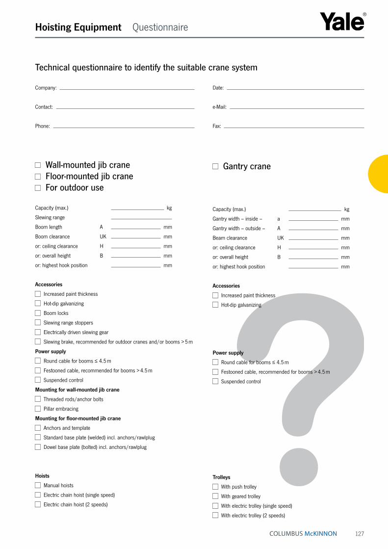
Gantry crane
Capacity (max.) kg
Gantry width – inside – a mm
Gantry width – outside – A mm
Beam clearance UK mm
or: ceiling clearance H mm
or: overall height B mm
or: highest hook position mm
Accessories
Increased paint thickness
Hot-dip galvanizing
Power supply
Round cable for booms ≤ 4.5 m
Festooned cable, recommended for booms > 4.5 m
Suspended control
Trolleys
With push trolley
With geared trolley
With electric trolley (single speed)
With electric trolley (2 speeds)
Technical questionnaire to identify the suitable crane system
Company: Date:
Contact: e-Mail:
Phone: Fax:
Wall-mounted jib crane Floor-mounted jib crane For outdoor use
Capacity (max.) kg
Slewing range
Boom length A mm
Boom clearance UK mm
or: ceiling clearance H mm
or: overall height B mm
or: highest hook position mm
Accessories
Increased paint thickness
Hot-dip galvanizing
Boom locks
Slewing range stoppers
Electrically driven slewing gear
Slewing brake, recommended for outdoor cranes and/or booms > 5 m
Power supply
Round cable for booms ≤ 4.5 m
Festooned cable, recommended for booms > 4.5 m
Suspended control
Mounting for wall-mounted jib crane
Threaded rods/anchor bolts
Pillar embracing
Mounting for floor-mounted jib crane
Anchors and template
Standard base plate (welded) incl. anchors/rawlplug
Dowel base plate (bolted) incl. anchors/rawlplug
Hoists
Manual hoists
Electric chain hoist (single speed)
Electric chain hoist (2 speeds)

128
Hoisting Equipment Wall-mounted jib cranes
Wall-mounted jib crane model PMSElevated boom with optimal height, slewing range 180°Lightweight, twist-free steel girder construction with low headroom. The boom is fitted with a bearing and a wall bracket for anchoring the crane to a concrete wall.
Mounting a jib crane to a wall, in combination with a festooned cable system, may lead to restrictions in the slewing range of the boom. This being the case, slew stoppers (buffers) should be fitted accordingly.
Mounting• Wall mounting, using threaded rods that go through the
wall and that are bolted to the wall with counter plates and nuts.
• Pillar embracing with anchor bolts and wall bracket. Bracket plate max. 500 mm, anchor bolts (threaded rods) max. 1000 mm.
• Alternative mounting systems on request.
Options• Slew stoppers (buffers) can be fitted on building site for
a pre-determined fixed slewing range.
• Slewing brake, to control the boom speed during slew-ing. Recommended for a boom length of more than 5 m or a headroom of more than 4 m. This prevents uncontrolled movement of the boom.
• Increased paint layer (120 µm) or hot-dip galvanisation for outdoor use.
• Manual locking device, to hold the boom in a fixed posi-tion (wind protection).
• Hoist cover for outdoor use.
Scope of delivery• The electrical system is equipped with a lockable main
switch, round cable power supply with cable support pipes for booms up to 4000 mm.
• From 4500 mm upwards, the boom is equipped with a festooned cable power supply. Due to cable sag on low cranes, we recommend the use of festooned cables even on short booms.
• Trolley stoppers at the front and at the back.
• Cranes are supplied with an operating manual and complete manufacturer‘s documentation.
Standard delivery programme model PMS
Model Capacity Boom length in mmkg 2000 2500 3000 3500 4000 4500 5000 5500 6000 6500 7000
PMS 50 50 • • • • • • • • • • •PMS 80 80 • • • • • • • • • • •PMS 125 125 • • • • • • • • • • •PMS 200 200 • • • • • • • • • • •PMS 250 250 • • • • • • • • • • •PMS 400 400 • • • • • • • • • • •PMS 500 500 • • • • • • • • • • •PMS 800 800 • • • • • • • • • • •PMS 1000 1000 • • • • • • • • • – –PMS 1600 1600 • • • • • • • – – – –PMS 2000 2000 • • • • • – – – – – –PMS 2500 2500 • • • – – – – – – – –
INFO
Mounting supports and walls are within the re-sponsibility of the user.
129
Hoisting Equipment User information
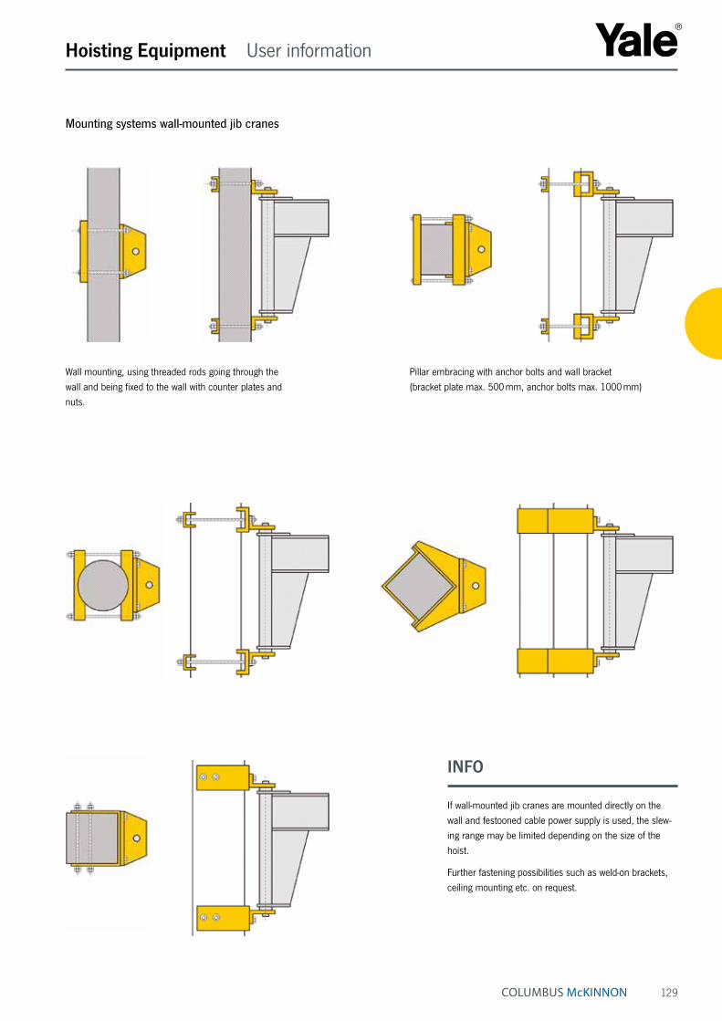
Mounting systems wall-mounted jib cranes
Wall mounting, using threaded rods going through the wall and being fixed to the wall with counter plates and nuts.
Pillar embracing with anchor bolts and wall bracket (bracket plate max. 500 mm, anchor bolts max. 1000 mm)
INFO
If wall-mounted jib cranes are mounted directly on the wall and festooned cable power supply is used, the slew-ing range may be limited depending on the size of the hoist.
Further fastening possibilities such as weld-on brackets, ceiling mounting etc. on request.
130
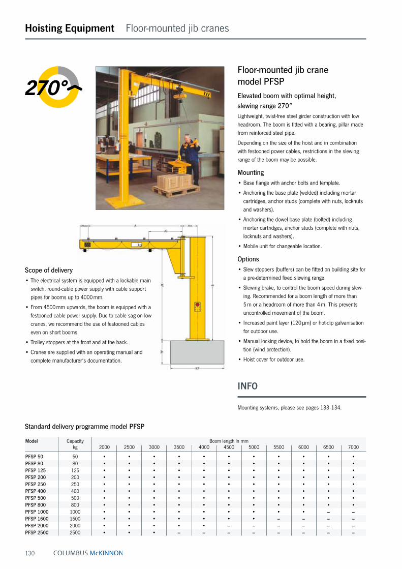
Floor-mounted jib crane model PFSPElevated boom with optimal height, slewing range 270°Lightweight, twist-free steel girder construction with low headroom. The boom is fitted with a bearing, pillar made from reinforced steel pipe.
Depending on the size of the hoist and in combination with festooned power cables, restrictions in the slewing range of the boom may be possible.
Mounting• Base flange with anchor bolts and template.
• Anchoring the base plate (welded) including mortar cartridges, anchor studs (complete with nuts, locknuts and washers).
• Anchoring the dowel base plate (bolted) including mortar cartridges, anchor studs (complete with nuts, locknuts and washers).
• Mobile unit for changeable location.
Options• Slew stoppers (buffers) can be fitted on building site for
a pre-determined fixed slewing range.
• Slewing brake, to control the boom speed during slew-ing. Recommended for a boom length of more than 5 m or a headroom of more than 4 m. This prevents uncontrolled movement of the boom.
• Increased paint layer (120 µm) or hot-dip galvanisation for outdoor use.
• Manual locking device, to hold the boom in a fixed posi-tion (wind protection).
• Hoist cover for outdoor use.
Hoisting Equipment Floor-mounted jib cranes
Scope of delivery• The electrical system is equipped with a lockable main
switch, round-cable power supply with cable support pipes for booms up to 4000 mm.
• From 4500 mm upwards, the boom is equipped with a festooned cable power supply. Due to cable sag on low cranes, we recommend the use of festooned cables even on short booms.
• Trolley stoppers at the front and at the back.
• Cranes are supplied with an operating manual and complete manufacturer‘s documentation.
Standard delivery programme model PFSP
Model Capacity Boom length in mmkg 2000 2500 3000 3500 4000 4500 5000 5500 6000 6500 7000
PFSP 50 50 • • • • • • • • • • •PFSP 80 80 • • • • • • • • • • •PFSP 125 125 • • • • • • • • • • •PFSP 200 200 • • • • • • • • • • •PFSP 250 250 • • • • • • • • • • •PFSP 400 400 • • • • • • • • • • •PFSP 500 500 • • • • • • • • • • •PFSP 800 800 • • • • • • • • • • •PFSP 1000 1000 • • • • • • • • • – –PFSP 1600 1600 • • • • • • • – – – –PFSP 2000 2000 • • • • • – – – – – –PFSP 2500 2500 • • • – – – – – – – –
INFO
Mounting systems, please see pages 133 -134.

131
Hoisting Equipment Floor-mounted jib cranes
Floor-mounted jib crane model PFMElevated boom with optimal height, slewing range 360°Lightweight, twist-free steel girder construction with low headroom. Compact rotating head for ideal construction dimensions; access from above ensures easy assembly. The boom is fitted with a roller bearing, pillar made from reinforced steel pipe.
Depending on the size of the hoist and in combination with festooned power cables, restrictions in the slewing range of the boom may be possible.
Mounting• Base flange with anchor bolts and template.
• Anchoring the base plate (welded) including mortar cartridges, anchor studs (complete with nuts, locknuts and washers).
• Anchoring the dowel base plate (bolted) including mortar cartridges, anchor studs (complete with nuts, locknuts and washers).
• Mobile unit for changeable location.
Options• Slew stoppers (buffers) can be fitted on building site for
a pre-determined fixed slewing range.
• Slewing brake, to control the boom speed during slew-ing. Recommended for a boom length of more than 5 m or a headroom of more than 4 m. This prevents uncontrolled movement of the boom.
• Increased paint layer (120 µm) or hot-dip galvanisation for outdoor use.
• Manual locking device, to hold the boom in a fixed posi-tion (wind protection).
• Hoist cover for outdoor use.
Scope of delivery• The electrical system is equipped with a lockable main
switch, round-cable power supply with cable support pipes for booms up to 4000 mm.
• From 4500 mm upwards, the boom is equipped with a festooned cable power supply. Due to cable sag on low cranes, we recommend the use of festooned cables even on short booms.
• Trolley stoppers at the front and at the back.
• Cranes are supplied with an operating manual and complete manufacturer‘s documentation.
Standard delivery programme model PFM
Model Capacity Boom length in mmkg 2000 2500 3000 3500 4000 4500 5000 5500 6000 6500 7000
PFM 50 50 • • • • • • • • • • •PFM 80 80 • • • • • • • • • • •PFM 125 125 • • • • • • • • • • •PFM 200 200 • • • • • • • • • • •PFM 250 250 • • • • • • • • • – –PFM 400 400 • • • • • • • – – – –PFM 500 500 • • • • • • – – – – –PFM 800 800 • • • – – – – – – – –PFM 1000 1000 • • – – – – – – – – –
INFO
Mounting systems, please see pages 133 -134.
132
Hoisting Equipment Floor-mounted jib cranes
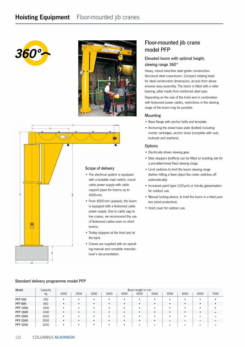
Floor-mounted jib crane model PFPElevated boom with optimal height, slewing range 360°Heavy, robust twist-free steel girder construction. Structural steel crane-boom. Compact rotating head for ideal construction dimensions; access from above ensures easy assembly. The boom is fitted with a roller bearing, pillar made from reinforced steel pipe.
Depending on the size of the hoist and in combination with festooned power cables, restrictions in the slewing range of the boom may be possible.
Mounting• Base flange with anchor bolts and template.
• Anchoring the dowel base plate (bolted) including mortar cartridges, anchor studs (complete with nuts, locknuts and washers).
Options• Electrically driven slewing gear.
• Slew stoppers (buffers) can be fitted on building site for a pre-determined fixed slewing range.
• Limit switches to limit the boom slewing range (before hitting a fixed object the motor switches off automatically).
• Increased paint layer (120 µm) or hot-dip galvanisation for outdoor use.
• Manual locking device, to hold the boom in a fixed posi-tion (wind protection).
• Hoist cover for outdoor use.
Scope of delivery• The electrical system is equipped
with a lockable main switch, round-cable power supply with cable support pipes for booms up to 4000 mm.
• From 4500 mm upwards, the boom is equipped with a festooned cable power supply. Due to cable sag on low cranes, we recommend the use of festooned cables even on short booms.
• Trolley stoppers at the front and at the back.
• Cranes are supplied with an operat-ing manual and complete manufac-turer‘s documentation.
Standard delivery programme model PFP
Model Capacity Boom length in mmkg 2000 2500 3000 3500 4000 4500 5000 5500 6000 6500 7000
PFP 500 500 • • • • • • • • • • •PFP 800 800 • • • • • • • • • • •PFP 1000 1000 • • • • • • • • • • •PFP 1600 1600 • • • • • • • • • • –PFP 2000 2000 • • • • • • • • • – –PFP 2500 2500 • • • • • • • – – – –PFP 3200 3200 • • • • • – – – – – –
133
Hoisting Equipment User information
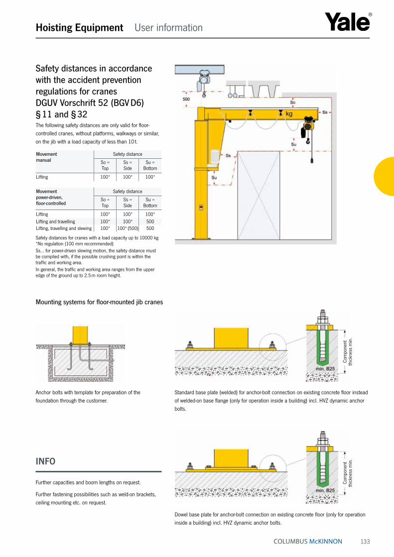
Mounting systems for floor-mounted jib cranes
Anchor bolts with template for preparation of the foundation through the customer.
Standard base plate (welded) for anchor-bolt connection on existing concrete floor instead of welded-on base flange (only for operation inside a building) incl. HVZ dynamic anchor bolts.
Dowel base plate for anchor-bolt connection on existing concrete floor (only for operation inside a building) incl. HVZ dynamic anchor bolts.
Com
pone
nt
thic
knes
s m
in.
Com
pone
nt
thic
knes
s m
in.INFO
Further capacities and boom lengths on request.
Further fastening possibilities such as weld-on brackets, ceiling mounting etc. on request.
Safety distances in accordance with the accident prevention regulations for cranes DGUV Vorschrift 52 (BGV D6) § 11 and § 32The following safety distances are only valid for floor-controlled cranes, without platforms, walkways or similar, on the jib with a load capacity of less than 10 t.
Movement manual
Safety distance
So = Top
Ss = Side
Su = Bottom
Lifting 100* 100* 100*
Movement power-driven, floor-controlled
Safety distance
So = Top
Ss = Side
Su = Bottom
Lifting 100* 100* 100*Lifting and travelling 100* 100* 500Lifting, travelling and slewing 100* 100* (500) 500
Safety distances for cranes with a load capacity up to 10000 kg *No regulation (100 mm recommended)Ss… for power-driven slewing motion, the safety distance must be complied with, if the possible crushing point is within the traffic and working area.In general, the traffic and working area ranges from the upper edge of the ground up to 2.5 m room height.

134
Hoisting Equipment User information
INFO
INFO
Plate dimensions, quantity, dimension and position of the chemical anchors depend on the crane type, load capac-ity and boom length of the crane (details and technical data according to the relevant crane data sheet).
Due to cable sag, we recommend that on low cranes festooned cables be used, even for a short boom length.
Operating conditions for standard and intermediate base plates• The thickness of the concrete floor slab for M 12 x 95
HVC dynamic anchor bolts must be min. 190 mm.
• The thickness of the concrete floor slab for M 16 x 105 HVC dynamic anchor bolts must be min. 210 mm.
• The concrete floor slab must be horizontal and even.
• The concrete quality must meet min. B25 or C20/25.
• Mounting with through bolts consisting of base plate, through bolts and counter plates (for ceiling thick-nesses up to 350 mm).
• Floor/wall mounting or floor/ceiling mounting on request.
Base plate for fastening pillar-mounted slewing jibs and slewing cranes without foundationSome pillar-mounted slewing jibs and slewing cranes can be mounted by means of a standard base plate or an dowel base plate. No foundation is required, easy and quick assembly on the customer’s existing reinforced concrete slab is possible. Potential tripping hazard by protruding locknuts, unmarked or unsecured plate edges must be clearly marked.
• The installation location of the crane must be selected in such a way that the base plate is mounted outside of traffic routes according to the German regulations for workplaces AStV para. 2. If this is not possible, the plate must be secured or marked in such a way that a hazard is avoided (e.g. by warning hatching along the edge of the plate).
• The base plate with tripping points must not protrude into escape routes or limit their prescribed min. widths.
• The measures for reducing hazards caused by tripping points must be taken by the operating company in cooperation with the safety expert.
• A warning sign as hazard reduction is a minimal measure and may not be sufficient in certain cases (e.g. in spite of warning signs, tripping incidences occur frequently, the warning sign is not recognised sufficiently in advance).
The smallest possible projection of the chemical anchor
over the crane base plate “X” with an M12 anchor is approx. 33 mm, with M16 approx. 37 mm. This dimen-sion can only be reached, if the concrete floor slab ex-ceeds the above-mentioned min. thickness. The max. projection of the chemical anchor, measured from floor level “Y”, is approx. 73 mm for M12 anchors
and approx. 86 mm for M16 anchors, with the relevant min. floor slab thickness.

135
Hoisting Equipment Moveable gantry cranes
Boom clearance (UK): Standard 2500 mm, other dimensions on request.
Gantry width - inside (dimension a): TDL-500/TDL-1000: Boom length A less 455 mm TDL-2000/TDL-3200: Boom length A less 500 mm
Standard delivery programme model TDL
Model Capacity Boom length in mmkg 2500 3000 3500 4000 4500 5000 5500 6000
TDL 500 500 • • • • • • • •TDL 1000 1000 • • • • • • • •TDL 2000 2000 • • • • • • • •TDL 3200 3200 • • • • • • • •
INFO
Further capacities and boom lengths on request.
Moveable gantry crane model TDLYalesystems gantry crane for use in all areas, from crafts-man‘s workshops, garages and industrial use. They are suitable for low to medium weight capacities and are also for outdoor use.
The cranes are moved by hand and are not dependant on a rail system. The guidelines for moving Yalesystems gantry cranes and transporting loads should be strictly followed.
Options• Increased paint layer (120 µm) or hot-dip galvanisation
for outdoor use.
• Hoist cover for outdoor use.
Scope of delivery• 3-part construction with 2 robust rectangular steel-bar
supports and 1 load carrier beam.
• Manually moveable, parking brake by threaded spindle.
• Power supply by festooned cables incl. flat cables, C type mounting rail, cable trolley, support arms and towing trolleys.
• Cranes are supplied with an operating manual and complete manufacturer‘s documentation.

136
Hoisting Equipment Light crane systems
Light crane system model YSKProfilesThe YSK-light crane system is based on three optimised steel profiles suitable for load ranges up to 2000 kg. A good weight vs. carrying capacity ratio ensures maxi-mum suspension distances leading to a reduced number of supporting structure and less suspension components.
The closed profile construction ensures increased durabil-ity of the YSK-light crane system as it protects the system agains dust. All profiles are surface treated with impact resistant powder coating and can be delivered in full 1-8 meters lengths. Other colours and surface treatments are available on request.
For easy and quick installation all connections are bolt-connections.
The patented trolley is characterized by an extraordinarly low noise level and a rolling resistance of approx 1 % of the moved load. YSK-light crane system brings ergonomic and quality to the working environment.
LOAD CAPACITY (deflection 1:350) Profile 125
8000
7000
6000
5000
4000
3000
2000
1000 50 80 125 250 320 500 630 1000 1250 1500 1600 2000 kg
6700
8000mm
47004200
2900
LOAD CAPACITY (deflection 1:350) Profile 200
8000
7000
6000
5000
4000
3000
2000
1000 50 80 125 250 320 500 630 1000 1250 1500 1600 2000 kg
3600
6500
4500
73008000
mm
3000 28002300
LOAD CAPACITY (deflection 1:350) Profile 260
8000
7000
6000
5000
4000
3000
2000
1000 50 80 125 250 320 500 630 1000 1250 1500 1600 2000 kg
5600
6900
8000mm
47004400
3600
Light crane system model YSKHoist trackThe YSK-hoist track is a versatile solution for one-way moving and lifting applications up to max. capacities of 1500 kg.
The YSK-hoist track is designed for easy assembly with standard joint connections and suspensions. It can be easily reconfigured to be adapted for changing conditions.
Hoist track – Suspension distance Tmax. in m
Capacity in kgProfile 50 80 125 250 320 500 630 1000 1250 1500
YSK-125 8 7.8 6.6 4.7 4.1 – – – – –YSK-200 8 8 8 8 8 7.2 6.2 4.4 3.6 3.1YSK-260 8 8 8 8 8 8 8 7.1 5.5 4.9
8 m is the max. profile standard length
Track length L
Suspension distance T

137
Hoisting Equipment Light crane systems
Light crane system model YSKSingle and double girder crane Low headroom raised constructionYSK-single or double girder cranes with raised construc-tion help are especially suitable for applications where the lifting height has to be maximized. Raised constructions are designed for locations with limited headroom or where a standard construction would not bring the required lifting height.
A system with a raised bridge can be suspended either from existing ceiling construction or from freestanding support frames.
Raised single girder crane
Profile mmTrack/Bridge C D E
YSK-125 199 159 264YSK-200 269 223 335YSK-260 329 283 395
Raised double girder crane
Profile mmTrack/Bridge B D E
YSK-125 57 159 264YSK-200 69 223 335YSK-260 69 283 395
E
c D
E
B D

138
Span S
Suspension distance T
Hoisting Equipment Light crane systems
Standard single girder crane
a b Smax. / Tmax. in meters at load capacity (kg)Profile mm mm 50 80 125 250 320 500 630 1000 1250 1500
YSK-125 150 294 8/8 7.8/7.4 6.6/6.6 4.0/4.3 3.0/3.8 – – – – –YSK-200 222 385 8/8 8/8 8/8 8/8 8/8 7.1/6.8 6.2/6 4.4/4.3 3.6/3.4 3.1/2.9YSK-260 282 445 8/8 8/8 8/8 8/8 8/8 8/8 8/8 6.6/6.2 5.5/5.7 4.7/4.4
8 m is the max. profile standard length
a b B Smax. / Tmax. in meters at load capacity (kg)Profile mm mm mm 80 125 250 320 500 630 1000 1250 1500 1600 2000
YSK-125 150 294 294 8/6.5 8/5.1 6.0/4 5.0/3.5 4.7/– – – – – – –YSK-200 222 385 392 8/8 8/8 8/8 8/8 8/6.4 8/5.7 7.2/4.3 6.5/3.7 5.3/3.2 5/3.1 4.0/2.7YSK-260 282 445 375 8/8 8/8 8/8 8/8 8/8 8/8 8/6.1 8/5.2 8/4.6 7.6/4.4 6.4/3.8
8 m is the max. profile standard length
Standard double girder crane
a
b
b
Ba
Light crane systemmodel YSKSingle and double girder craneYSK-single and double girder cranes are user friendly work station cranes. Their coverage is extensive and swinging of the load is minimized as the loaded push trolley centralises itself automatically to the right lifting position.
YSK-single girder crane is the most ergonomic solution due to its three dimensional construction and light own weight. With a double girder crane the load capacity is doubled and lifting height increased as the hoistis suspended from a hoist saddle locatedbetween the bridge profiles.
Span S
Suspension distance T

139
DSConcrete beam suspension
ESSide suspension
HSSuspension to inclined I-girder
LSDistance suspensionto I-girder
JSCollar suspension to I-girder
ASI-girder suspension
BSCeiling suspension
CSDistance suspension
FSU-shape suspension
HDDistance suspension to inclined I-girder
Hoisting Equipment Light crane systems
Light crane system model YSKFreestanding support framesYSK-freestanding support frames are designed for loca-tions where the ceiling is not designed to support the load of the crane. This type of crane is also a professional solution for applications where the crane systems need to be repositioned to suit changes in the layout of the shopfloor.
Standard suspensions
Suspension type, distance DProfile AS BS CS DS ES FS HS HD LS JS
YSK-125 123 ± 15 123 ± 15 < 500 ¹ 218 ± 15 104 ± 15 105 ± 15 210 ± 15 < 260 ¹ < 500 ¹ –YSK-200 167 ± 16 167 ± 16 < 500 ¹ 271 ± 16 136 ± 16 139 ± 16 248 ± 16 < 200 ¹ < 500 ¹ 176 ± 16YSK-260 167 ± 16 167 ± 16 < 500 ¹ 271 ± 16 136 ± 16 139 ± 16 248 ± 16 < 200 ¹ < 500 ¹ 176 ± 16
¹ for longer distances side support must be used.
Freestanding support frames
Load capacity, kg 50 - 2000Total width G, m 4.5 - 8.56Total height H, m 3 - 4 - 5Frame width J, m 4.18 - 8.16Single or double bridge width W, m 2 - 8
G
W
J
H
DDD
DD D D
D
DD
Light crane systemmodel YSKArticulating supensionsYSK-light crane systems include various types of articulat-ing standard suspensions to mount the crane to the ceiling construction.

140
Hoisting Equipment Power supply
Festooned cable systemThe Yale festooned cable system kit contains all the parts necessary to install a power supply.
Features• The PVC flat cable 4 x 2.5 mm² is suitable for all elec-
tric hoists with a power consumption of up to 25 A.
• The line sag is 700 mm. The cable and towing trolleys are made from plastic and can carry loads of up to 10 kg.
• The rollers are fitted with bronze bushes resp. ball bearings.
• The C-rail, rail support brackets and rail connectors are zinc-plated for added protection against corrosion.
Options• Mounting kit consisting of support arm and girder clips
for connection to the beam.
• Towing arm for towing trolley.
Scope of delivery• 1 End clamp
• 1 End stop
• 1 Towing trolley
• 2 End caps
• 2 FI-fittings with locknuts
• 1 Main switch 400 V, 50 Hz
C-Rail
Rail support bracket
Rail connector
Girder clip
Support arm
Cable trolley
Towing trolley
End clamp
Towing arm
Flat cable
Main switch
INFO
Quantity of units dependant on track length.

141
Hoisting Equipment Power supply
C-RailGirder clip Support arm
60
max. 40
max. 20
60
500 mm
Scope of delivery festooned cable systems
Model EAN-No. 4025092*
EAN-No. Mounting kit4025092*
C-rails track length
m
Transport distance max.
m
PVC flat cable
m
Numbers of
cable trolleys
Rail support bracket
Rail connector
Festooned cable 4 m C-rail track length *059305 *059398 4 3.5 9 2 4 0Festooned cable 6 m C-rail track length *059312 *059404 6 5.4 11 3 5 1Festooned cable 8 m C-rail track length *059329 *059411 8 7.3 13 5 6 1Festooned cable 10 m C-rail track length *059336 *059428 10 9.2 15 6 7 2Festooned cable 12 m C-rail track length *059343 *059435 12 11.0 17 8 8 2Festooned cable 14 m C-rail track length *059350 *059442 14 12.9 19 9 9 3Festooned cable 16 m C-rail track length *059367 *059459 16 14.8 21 11 10 3Festooned cable 18 m C-rail track length *059374 *059466 18 16.7 23 12 11 4Festooned cable 20 m C-rail track length *059381 *059473 20 18.5 25 14 12 4
Cable trolley Towing trolley Rail support bracket Rail connector C-Rail
54
8025
80
50
2415
125
36123
53
15
75
100333
31
M8
4084
60
15
32
30
3
I32
1,5
12
26
30
100333
31
I32
1,5
12
26
30
INFO
Optional: Mounting kit consisting of support arm and girder clips for connection to the beam.
Special applications e.g. for curves or cable trolley for round cables on request.
Rail support bracket