Embed Size (px)
Citation preview

HOM COUPLER DESIGN FOR CEPC CAVITIES*
H. J. Zheng†, F. B. Meng, J. Y. Zhai Key Laboratory of Particle Acceleration Physics and Technology, Institute of High Energy Physics,
CAS, Beijing 100049, China
Abstract In this paper, it will be presented the higher order
mode (HOM) coupler design for the Circular Electron-Positron Collider (CEPC) 650 MHz 2-cell cavity. The higher order modes excited by the intense beam bunches must be damped to avoid additional cryogenic loss and multi-bunch instabilities. To keep the beam stable, the impedance budget and the HOM damping requirement are given. A double notch coaxial HOM coupler, which will be mounted on the beam pipe, is planned to extract the HOM power below the cut-off frequency of the beam pipe. This paper summarizes the RF design of the HOM coupler, tolerance analysis, thermal analysis as well as mechanical structures.
INTRODUCTION With the discovery of the Higgs boson at the LHC in
2012, the world’s high energy physics (HEP) community is interested in future large circular colliders to study the Higgs boson. Because the Higgs mass is low (126 GeV), a circular e+e- collider can serve as a Higgs factory. The Institute of High Energy Physics (IHEP) in Beijing, in collaboration with a number of other institutes, has launched a study of a 50-100 km ring collider [1]. It will serve as an e+e- collider for a Higgs factory with the name of Circular Electron-Positron Collider (CEPC). A Preliminary Conceptual Design Report (Pre-CDR) was published in March, 2015 [2]. The e+e- beams are in the same beam pipe with a pretzel orbit, which is not suitable for a high luminosity Z factory. To solve the problem, a double ring scheme was raised, and the machine circumference was increased to 100 km [3]. The baseline SRF system layout and parameters are chosen to meet the minimum luminosity requirement for each operating energy, and with possible higher luminosity [4].
DAMPING REQUIREMENT The baseline of the collider is a double-ring with 650
MHz 2-cell cavities shared between the two collider rings [4, 5]. In a storage ring, the beam instabilities in both the longitudinal and transverse directions caused by the RF system are mainly from the cavities themselves. To keep the beam stable, the radiation damping time should be less than the rise time of the multi-bunch instability. The HOMs of the cavities must be damped sufficiently to prevent coupled bunch instabilities and to limit parasitic mode losses. To damp different polarization HOMs, at
least two HOM couplers per cavity are needed. The couplers need to damp the HOMs at frequencies from 780 to1471 MHz as shown in Fig. 1.
Figure 1: 650 MHz 2-cell cavity mode spectrum and the beam pipe cut-off frequency.
The average power losses can be calculated as single pass excitation. As shown in Fig. 2, HOM power damping of 0.47 kW for each 650 MHz 2-cell cavity is required for the CEPC collider. Resonant excitation should be considered especially for the low frequency modes below cut-off. The cut-off frequency of the waveguide modes for the beam pipe are 1.471 GHz (TM01) and 1.126 GHz (TE11). All the HOM power below the cut-off frequency should be coupled by the HOM coupler which mounted on the beam pipe and the propagating modes will be absorbed by two HOM absorbers at room temperature outside the cryomodule.
Figure 2: Frequency distribution of HOM power (H design).
HOM COUPLER DESIGN SCHEME The HOM coupler design must be optimized for the
operating frequency (high damping) and the HOM spectrum (low damping) of the cavities. A loop type
____________________________________________
* This study was supported by National Key Programme for S&T Research and Development (Grant NO.: 2016YFA0400400). † E-mail: [email protected]
18th International Conference on RF Superconductivity SRF2017, Lanzhou, China JACoW PublishingISBN: 978-3-95450-191-5 doi:10.18429/JACoW-SRF2017-MOPB028
Projects/FacilitiesProgress
MOPB028115
Cont
entf
rom
this
wor
km
aybe
used
unde
rthe
term
soft
heCC
BY3.
0lic
ence
(©20
17).
Any
distr
ibut
ion
ofth
isw
ork
mus
tmai
ntai
nat
tribu
tion
toth
eau
thor
(s),
title
ofth
ew
ork,
publ
isher
,and
DO
I.
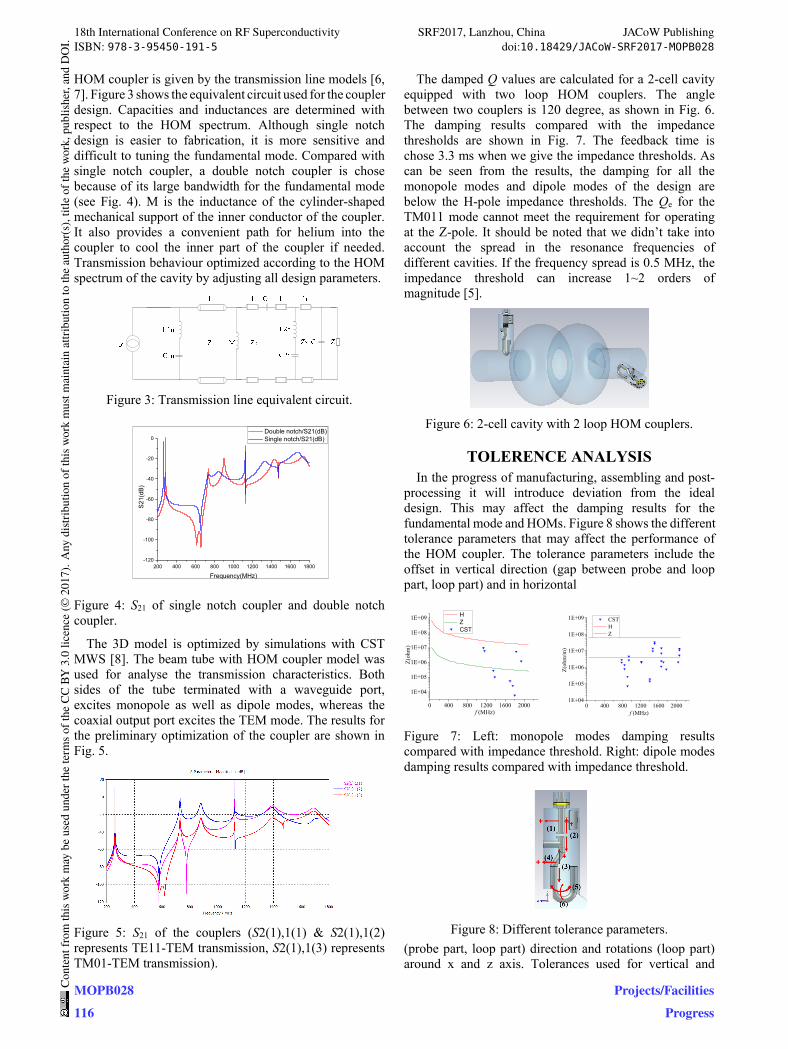
HOM coupler is given by the transmission line models [6, 7]. Figure 3 shows the equivalent circuit used for the coupler design. Capacities and inductances are determined with respect to the HOM spectrum. Although single notch design is easier to fabrication, it is more sensitive and difficult to tuning the fundamental mode. Compared with single notch coupler, a double notch coupler is chose because of its large bandwidth for the fundamental mode (see Fig. 4). M is the inductance of the cylinder-shaped mechanical support of the inner conductor of the coupler. It also provides a convenient path for helium into the coupler to cool the inner part of the coupler if needed. Transmission behaviour optimized according to the HOM spectrum of the cavity by adjusting all design parameters.
Figure 3: Transmission line equivalent circuit.
200 400 600 800 1000 1200 1400 1600 1800-120
-100
-80
-60
-40
-20
0
S21
(dB
)
Frequency(MHz)
Double notch/S21(dB) Single notch/S21(dB)
Figure 4: S21 of single notch coupler and double notch coupler.
The 3D model is optimized by simulations with CST MWS [8]. The beam tube with HOM coupler model was used for analyse the transmission characteristics. Both sides of the tube terminated with a waveguide port, excites monopole as well as dipole modes, whereas the coaxial output port excites the TEM mode. The results for the preliminary optimization of the coupler are shown in Fig. 5.
Figure 5: S21 of the couplers (S2(1),1(1) & S2(1),1(2) represents TE11-TEM transmission, S2(1),1(3) represents TM01-TEM transmission).
The damped Q values are calculated for a 2-cell cavity equipped with two loop HOM couplers. The angle between two couplers is 120 degree, as shown in Fig. 6. The damping results compared with the impedance thresholds are shown in Fig. 7. The feedback time is chose 3.3 ms when we give the impedance thresholds. As can be seen from the results, the damping for all the monopole modes and dipole modes of the design are below the H-pole impedance thresholds. The Qe for the TM011 mode cannot meet the requirement for operating at the Z-pole. It should be noted that we didn’t take into account the spread in the resonance frequencies of different cavities. If the frequency spread is 0.5 MHz, the impedance threshold can increase 1~2 orders of magnitude [5].
Figure 6: 2-cell cavity with 2 loop HOM couplers.
TOLERENCE ANALYSIS In the progress of manufacturing, assembling and post-
processing it will introduce deviation from the ideal design. This may affect the damping results for the fundamental mode and HOMs. Figure 8 shows the different tolerance parameters that may affect the performance of the HOM coupler. The tolerance parameters include the offset in vertical direction (gap between probe and loop part, loop part) and in horizontal
0 400 800 1200 1600 2000
1E+04
1E+05
1E+06
1E+07
1E+08
1E+09 H Z CST
Z(o
hm)
f (MHz)0 400 800 1200 1600 2000
1E+04
1E+05
1E+06
1E+07
1E+08
1E+09 CST H Z
Z(o
hm/m
)
f (MHz)
Figure 7: Left: monopole modes damping results compared with impedance threshold. Right: dipole modes damping results compared with impedance threshold.
Figure 8: Different tolerance parameters.
(probe part, loop part) direction and rotations (loop part) around x and z axis. Tolerances used for vertical and
18th International Conference on RF Superconductivity SRF2017, Lanzhou, China JACoW PublishingISBN: 978-3-95450-191-5 doi:10.18429/JACoW-SRF2017-MOPB028
MOPB028116
Cont
entf
rom
this
wor
km
aybe
used
unde
rthe
term
soft
heCC
BY3.
0lic
ence
(©20
17).
Any
distr
ibut
ion
ofth
isw
ork
mus
tmai
ntai
nat
tribu
tion
toth
eau
thor
(s),
title
ofth
ew
ork,
publ
isher
,and
DO
I.
Projects/FacilitiesProgress
horizontal direction is ±0.5 mm. Tolerances used for rotations around x and z axis is ±0.5 deg. Figures 9 ~ 11 show the influence of different tolerance parameters on the transmission behaviour of the HOM coupler. The probe offset on horizontal direction only affect the bandwidth of fundamental mode and has little effect on HOMs as shown in Fig. 10. Because of the large bandwidth of the fundamental mode, the tolerance affects only a little on the fundamental mode frequency. Fig. 11 shows that the gap between probe and loop part mainly affects the frequency of the first and second peak on S21 curve. Figures 12~15 show that the other tolerances have little effect on both fundamental mode and HOMs.
Figure 9: Left: probe offset on horizontal direction. Right: Gap (between probe and loop part) offset on vertical direction.
Figure 10: Left: loop offset on vertical direction. Right: loop offset on horizontal direction.
Figure 11: Left: loop rotation around x axis. Right: loop rotation around z axis.
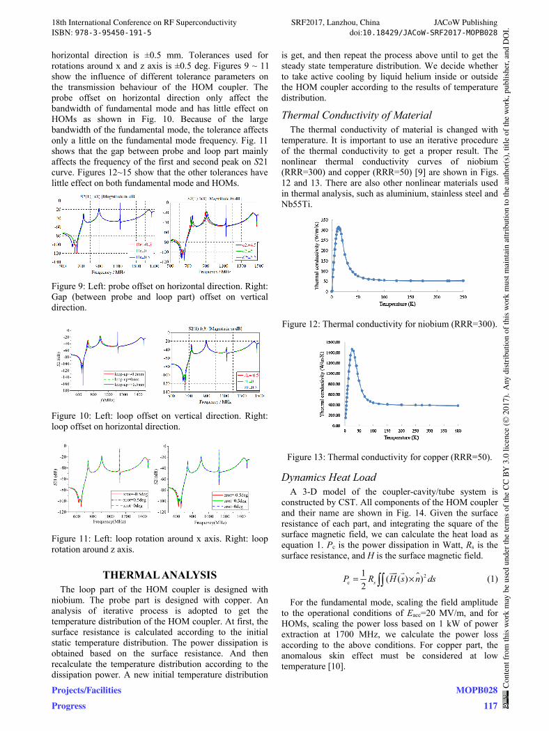
THERMAL ANALYSIS The loop part of the HOM coupler is designed with
niobium. The probe part is designed with copper. An analysis of iterative process is adopted to get the temperature distribution of the HOM coupler. At first, the surface resistance is calculated according to the initial static temperature distribution. The power dissipation is obtained based on the surface resistance. And then recalculate the temperature distribution according to the dissipation power. A new initial temperature distribution
is get, and then repeat the process above until to get the steady state temperature distribution. We decide whether to take active cooling by liquid helium inside or outside the HOM coupler according to the results of temperature distribution.
Thermal Conductivity of Material The thermal conductivity of material is changed with
temperature. It is important to use an iterative procedure of the thermal conductivity to get a proper result. The nonlinear thermal conductivity curves of niobium (RRR=300) and copper (RRR=50) [9] are shown in Figs. 12 and 13. There are also other nonlinear materials used in thermal analysis, such as aluminium, stainless steel and Nb55Ti.
Figure 12: Thermal conductivity for niobium (RRR=300).
Figure 13: Thermal conductivity for copper (RRR=50).
Dynamics Heat Load A 3-D model of the coupler-cavity/tube system is
constructed by CST. All components of the HOM coupler and their name are shown in Fig. 14. Given the surface resistance of each part, and integrating the square of the surface magnetic field, we can calculate the heat load as equation 1. Pc is the power dissipation in Watt, Rs is the surface resistance, and H is the surface magnetic field.
2c
1( ( ) )
2 sP R H s n ds= ×
(1)
For the fundamental mode, scaling the field amplitude to the operational conditions of Eacc=20 MV/m, and for HOMs, scaling the power loss based on 1 kW of power extraction at 1700 MHz, we calculate the power loss according to the above conditions. For copper part, the anomalous skin effect must be considered at low temperature [10].
18th International Conference on RF Superconductivity SRF2017, Lanzhou, China JACoW PublishingISBN: 978-3-95450-191-5 doi:10.18429/JACoW-SRF2017-MOPB028
Projects/FacilitiesProgress
MOPB028117
Cont
entf
rom
this
wor
km
aybe
used
unde
rthe
term
soft
heCC
BY3.
0lic
ence
(©20
17).
Any
distr
ibut
ion
ofth
isw
ork
mus
tmai
ntai
nat
tribu
tion
toth
eau
thor
(s),
title
ofth
ew
ork,
publ
isher
,and
DO
I.
Figure 14: 3D model used for the HOM coupler.
Results 2 W coaxial line static heat load to HOM coupler is
considered at initial static thermal analysis, and the initial static temperature distribution is obtained as shown in Fig. 15 (a). A 5 K anchor is added on the top of the coupler when we make the thermal calculation. According to the temperature distribution T, calculate the surface resistance Rs and power loss. The initial static thermal analysis shows that the temperature of the loop part is close to the critical temperature. In such conditions, the dynamic heat loss of the loop part is around 15 W. The loop part quenches after we load the surface heat loss as shown in Fig. 15 (b).
Figure 15: (a) initial static temperature distribution (b) temperature distribution after loaded the surface heat loss.
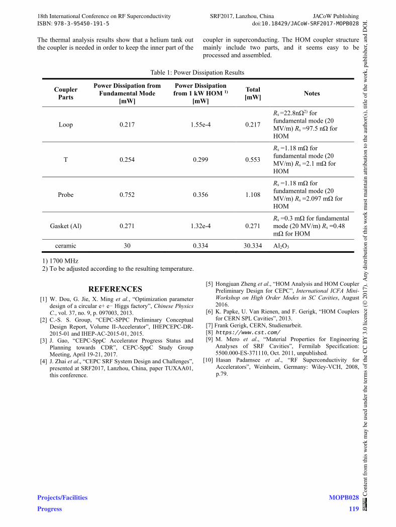
In order to keep the loop part in superconducting, a helium tank outside the HOM coupler is needed. The initial static thermal analysis results after introduce the helium tank is shown in Fig. 16. The boundary condition of the helium tank was set to 2.5 K. It shows that the loop part is in superconducting. The power dissipation of different parts from fundamental mode and 1 kW HOM power is listed on Table 1. After loaded the surface heat loss, the dynamic temperature distribution is shown in Fig. 17. It can be seen from the analysis that the power dissipation caused by the fundamental mode and 1 kW HOM is only in the mW range. And the temperature increase caused by the power dissipation is small, so the loop part is still in superconducting.
Figure 16: Initial static temperature distribution after introduce helium tank.
(a) (b)
Figure 17: Temperature distribution after loaded the surface heat loss.
MECHANICAL STRUCTURE The HOM coupler structure mainly include two parts. One part constitutes a niobium loop, a niobium shell, two flanges and helium jacket made of Nb55Ti. The other part constitutes a ceramic, a copper probe and stainless steel flange. The structures which are made of niobium and Nb55Ti will be e-beam welded. The welding procedure of ceramic with copper and ceramic with stainless steel is brazing. The processing and assembling steps are easily understand as shown in Fig. 18.
Figure 18: Processing and assembling steps.
CONCLUSIONS In this paper, we give a reasonable HOM coupler
design for CEPC. The frequency distribution of the HOM power shows that the total HOM power for each cavity is 0.47 kW.
A double notch HOM coupler is designed with respect to the transmission line model. After the double notch HOM coupler introduced to the cavity, almost all the HOMs are under the impedance thresholds.
Different tolerance parameters are considered in the progress of manufacturing, assembling and post-processing. The analysis results show that different tolerance parameters affect the performance of the HOM coupler only a little. If the deviation controlled well, the coupler does not need to be tuned after processing.
18th International Conference on RF Superconductivity SRF2017, Lanzhou, China JACoW PublishingISBN: 978-3-95450-191-5 doi:10.18429/JACoW-SRF2017-MOPB028
MOPB028118
Cont
entf
rom
this
wor
km
aybe
used
unde
rthe
term
soft
heCC
BY3.
0lic
ence
(©20
17).
Any
distr
ibut
ion
ofth
isw
ork
mus
tmai
ntai
nat
tribu
tion
toth
eau
thor
(s),
title
ofth
ew
ork,
publ
isher
,and
DO
I.
Projects/FacilitiesProgress
The thermal analysis results show that a helium tank out the coupler is needed in order to keep the inner part of the
coupler in superconducting. The HOM coupler structure mainly include two parts, and it seems easy to be processed and assembled.
Table 1: Power Dissipation Results
Coupler Parts
Power Dissipation from Fundamental Mode
[mW]
Power Dissipation from 1 kW HOM 1)
[mW]
Total [mW]
Notes
Loop 0.217 1.55e-4 0.217
Rs =22.8nΩ2) for fundamental mode (20 MV/m) Rs =97.5 nΩ for HOM
T 0.254 0.299 0.553
Rs =1.18 mΩ for fundamental mode (20 MV/m) Rs =2.1 mΩ for HOM
Probe 0.752 0.356 1.108
Rs =1.18 mΩ for fundamental mode (20 MV/m) Rs =2.097 mΩ for HOM
Gasket (Al) 0.271 1.32e-4 0.271 Rs =0.3 mΩ for fundamental mode (20 MV/m) Rs =0.48 mΩ for HOM
ceramic 30 0.334 30.334 Al2O3
1) 1700 MHz 2) To be adjusted according to the resulting temperature.
REFERENCES [1] W. Dou, G. Jie, X. Ming et al., “Optimization parameter
design of a circular e+ e− Higgs factory”, Chinese Physics C., vol. 37, no. 9, p. 097003, 2013.
[2] C.-S. S. Group, “CEPC-SPPC Preliminary Conceptual Design Report, Volume II-Accelerator”, IHEPCEPC-DR-2015-01 and IHEP-AC-2015-01, 2015.
[3] J. Gao, “CEPC-SppC Accelerator Progress Status and Planning towards CDR”, CEPC-SppC Study Group Meeting, April 19-21, 2017.
[4] J. Zhai et al., “CEPC SRF System Design and Challenges”, presented at SRF2017, Lanzhou, China, paper TUXAA01, this conference.
[5] Hongjuan Zheng et al., “HOM Analysis and HOM Coupler Preliminary Design for CEPC”, International ICFA Mini-Workshop on High Order Modes in SC Cavities, August 2016.
[6] K. Papke, U. Van Rienen, and F. Gerigk, “HOM Couplers for CERN SPL Cavities”, 2013.
[7] Frank Gerigk, CERN, Studienarbeit. [8] https://www.cst.com/ [9] M. Mero et al., “Material Properties for Engineering
Analyses of SRF Cavities”, Fermilab Specification: 5500.000-ES-371110, Oct. 2011, unpublished.
[10] Hasan Padamsee et al., “RF Superconductivity for Accelerators”, Weinheim, Germany: Wiley-VCH, 2008, p.79.
18th International Conference on RF Superconductivity SRF2017, Lanzhou, China JACoW PublishingISBN: 978-3-95450-191-5 doi:10.18429/JACoW-SRF2017-MOPB028
Projects/FacilitiesProgress
MOPB028119
Cont
entf
rom
this
wor
km
aybe
used
unde
rthe
term
soft
heCC
BY3.
0lic
ence
(©20
17).
Any
distr
ibut
ion
ofth
isw
ork
mus
tmai
ntai
nat
tribu
tion
toth
eau
thor
(s),
title
ofth
ew
ork,
publ
isher
,and
DO
I.