Embed Size (px)
Citation preview
• Homework• Quiz 3• Student
Perspective• System of
Equations• Bode Plots
Examples• Module IV
Announcements
No more Pre- Lab Module Homework
(Pre-Lab for Module V cancelled)
New Report Template (short and simple) – apply to Module III
New Report Rubric – apply to Module III
Homework-due 2/27 (Najera), due 3/2 (Quinones)
P15 and P16
Pre-Lab Module IV
Module IV: Build and Analyze 3 types of filters.
SUCCESS POINTS:
• REPORT WRITING –
CHECK TO MAKE SURE
EVERYTHING YOU SAY
REFER DIRECTLY TO
YOUR TABLES AND
GRAPHS?
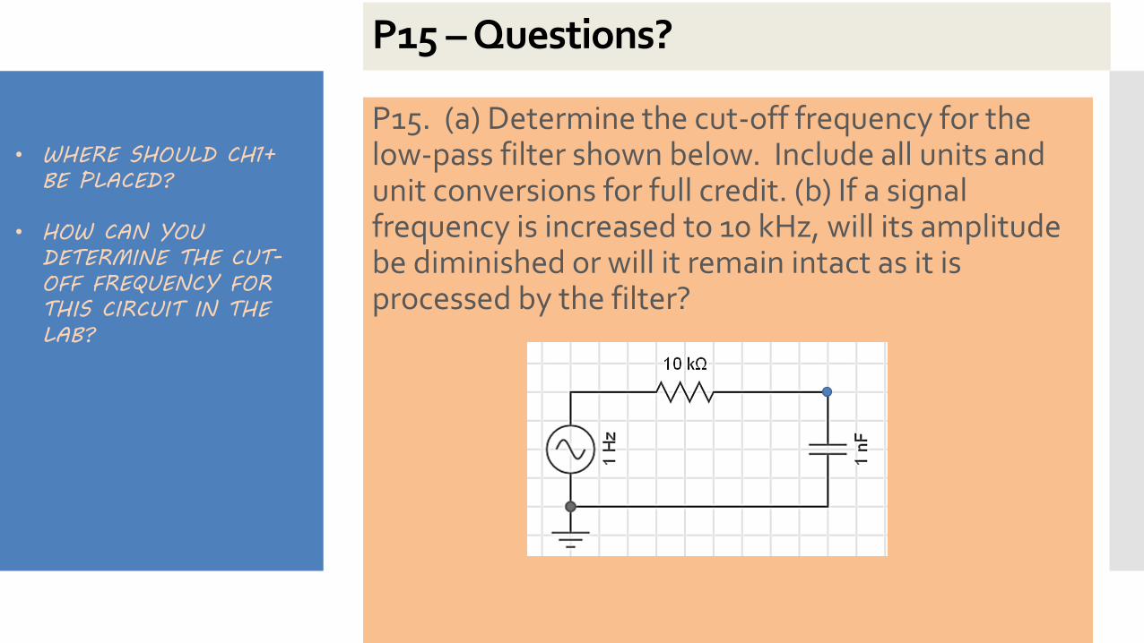
P15 – Questions?
P15. (a) Determine the cut-off frequency for the low-pass filter shown below. Include all units and unit conversions for full credit. (b) If a signal frequency is increased to 10 kHz, will its amplitude be diminished or will it remain intact as it is processed by the filter?
• WHERE SHOULD CH1+
BE PLACED?
• HOW CAN YOU
DETERMINE THE CUT-
OFF FREQUENCY FOR
THIS CIRCUIT IN THE
LAB?
P16 – Questions?
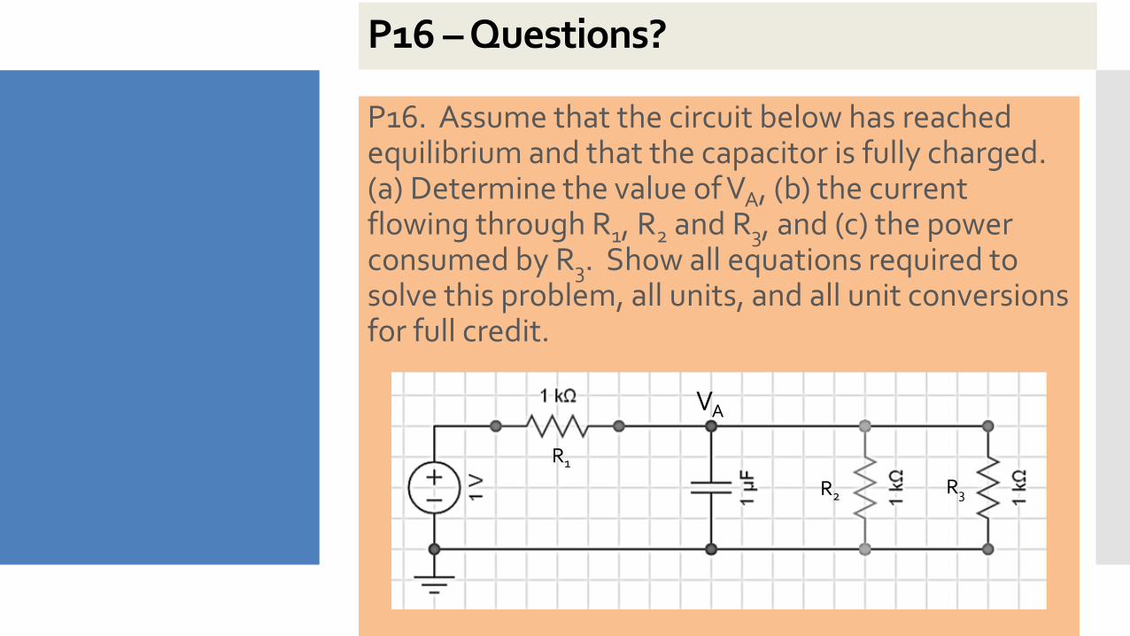
P16. Assume that the circuit below has reached equilibrium and that the capacitor is fully charged. (a) Determine the value of VA, (b) the current flowing through R1, R2 and R3, and (c) the power consumed by R3. Show all equations required to solve this problem, all units, and all unit conversions for full credit.
VA
R1
R2 R3
Team Exercise
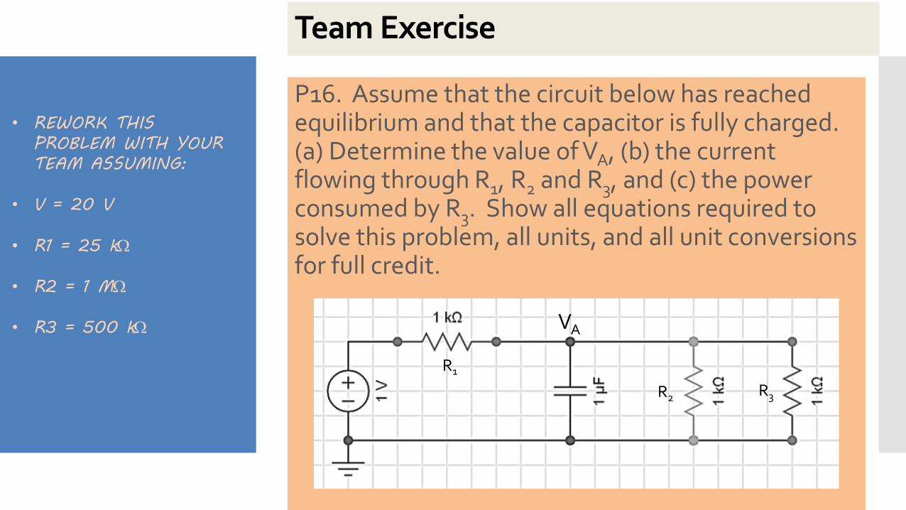
P16. Assume that the circuit below has reached equilibrium and that the capacitor is fully charged. (a) Determine the value of VA, (b) the current flowing through R1, R2 and R3, and (c) the power consumed by R3. Show all equations required to solve this problem, all units, and all unit conversions for full credit.
• REWORK THIS
PROBLEM WITH YOUR
TEAM ASSUMING:
• V = 20 V
• R1 = 25 k
• R2 = 1 M
• R3 = 500 k VA
R1
R2 R3
Quiz 3 – Power Calculations (20 pts)
• Please clear desks and turn off phones and put them in back packs
• You need pencil, straight edge and calculator
• 15 minutes
• Keep eyes on your own paper
• Follow same format as for homework
READ
INSTRUCTIONS
CAREFULLY!!!
Student Response to Module IRead each item carefully. Using the scale below, please circle the number that best describes the reason why you were ENGAGED IN THE MODULE I ACTIVITY in the lab. Answer each item according to the scale below.
1 - corresponds not at all
2 - corresponds a very little
3 - corresponds a little
4 - corresponds moderately
5 - corresponds enough
6 - corresponds a lot
7 - corresponds exactly
https://survey.az1.qualtrics.com/jfe/form/SV_emkJ9PDi3jmVEt7
YOUR OPINION
MATTERS.
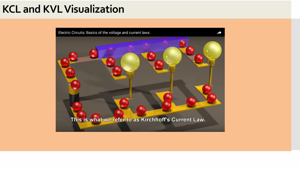
Introduction to Kirchhoff’s Current Law and Kirchhoff’s Voltage Law
Key Method to Analyze Circuits
Applies to all Circuits
Sometimes result is a System of Equations
KCL
KVL
System of Equations Calculations
Adding Equations
Cramer’s Rule
Calculator/Computer
WHY DO WE
NEED TO SOLVE
A “SYSTEM OF
EQUATIONS”?
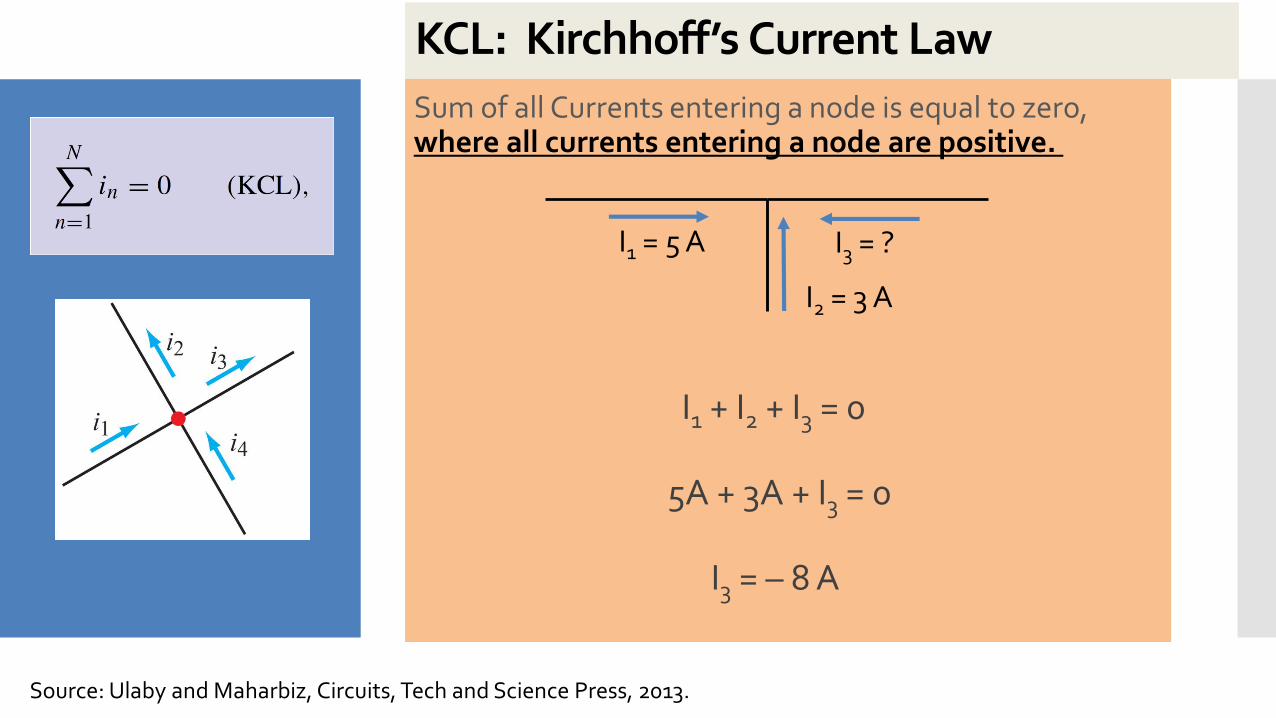
xxKCL: Kirchhoff’s Current Law
Sum of all Currents entering a node is equal to zero, where all currents entering a node are positive.
I1 = 5 A
I2 = 3 A
I3 = ?
I1 + I2 + I3 = 0
I3 = – 8 A
5A + 3A + I3 = 0
Source: Ulaby and Maharbiz, Circuits, Tech and Science Press, 2013.
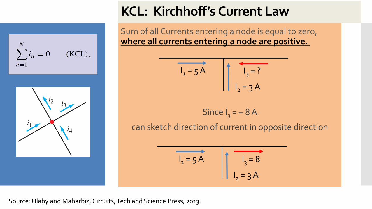
xxKCL: Kirchhoff’s Current Law
Sum of all Currents entering a node is equal to zero, where all currents entering a node are positive.
Since I3 = – 8 A
can sketch direction of current in opposite direction
I1 = 5 A
I2 = 3 A
I3 = 8
I1 = 5 A
I2 = 3 A
I3 = ?
Source: Ulaby and Maharbiz, Circuits, Tech and Science Press, 2013.
xxKCL: Kirchhoff’s Current Law
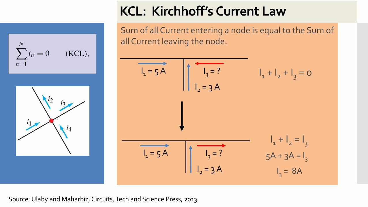
I1 + I2 = I3
I3 = 8A
5A + 3A = I3
Sum of all Current entering a node is equal to the Sum of all Current leaving the node.
I1 = 5 A
I2 = 3 A
I3 = ?
I1 = 5 A
I2 = 3 A
I3 = ?
I1 + I2 + I3 = 0
Source: Ulaby and Maharbiz, Circuits, Tech and Science Press, 2013.
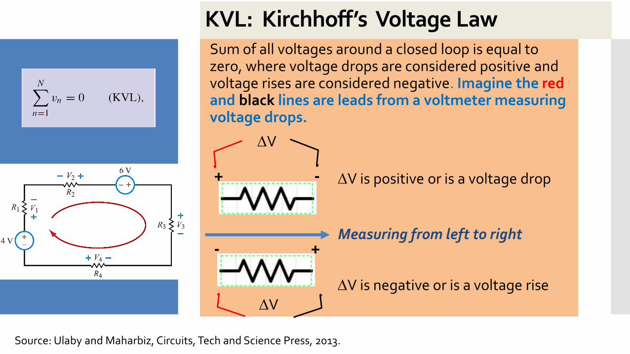
xxKVL: Kirchhoff’s Voltage LawSum of all voltages around a closed loop is equal to zero, where voltage drops are considered positive and voltage rises are considered negative. Imagine the redand black lines are leads from a voltmeter measuring voltage drops.
+ - V is positive or is a voltage drop
- +
V
V is negative or is a voltage riseV
Measuring from left to right
Source: Ulaby and Maharbiz, Circuits, Tech and Science Press, 2013.
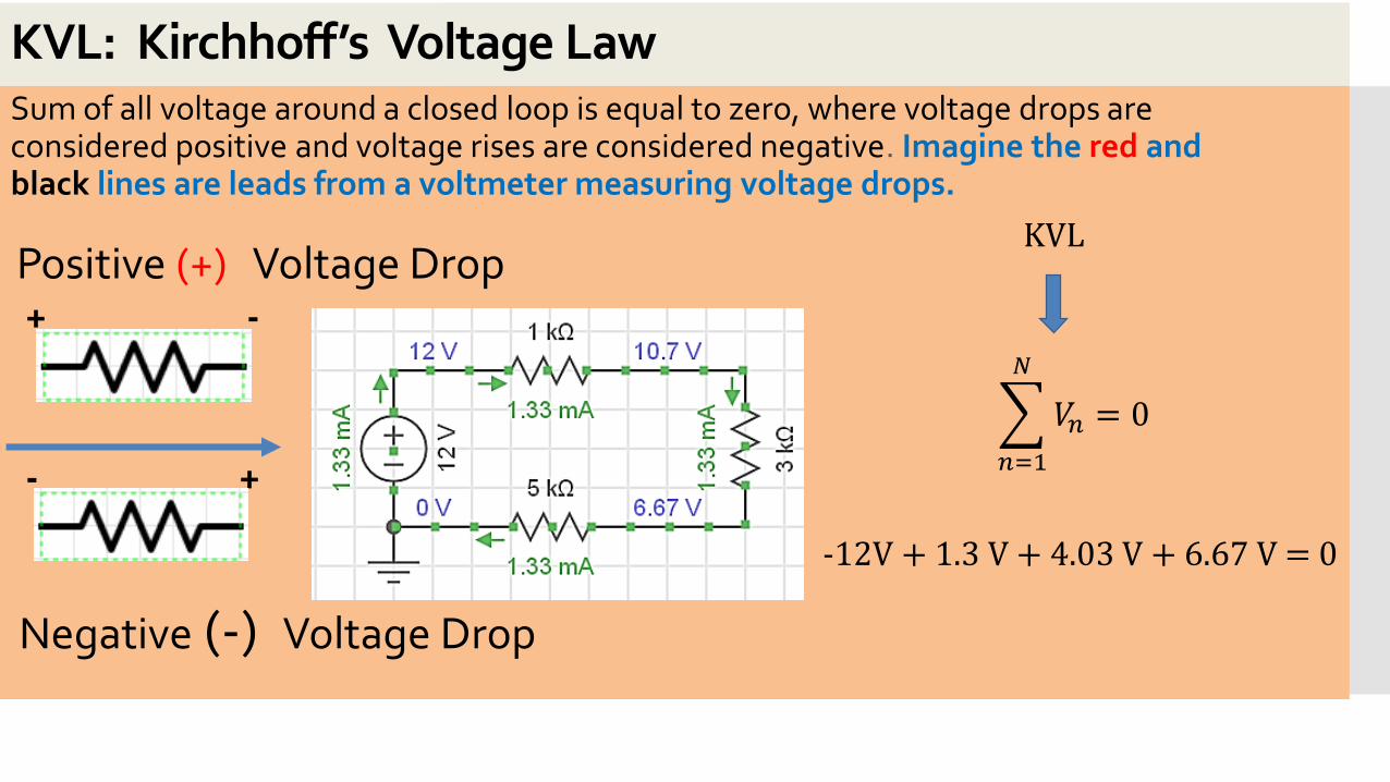
xxKVL: Kirchhoff’s Voltage LawSum of all voltage around a closed loop is equal to zero, where voltage drops are considered positive and voltage rises are considered negative. Imagine the red and black lines are leads from a voltmeter measuring voltage drops.
-12V + 1.3 V + 4.03 V + 6.67 V = 0
KVL
+ -
Positive (+) Voltage Drop
- +
Negative (-) Voltage Drop
𝑛=1
𝑁
𝑉𝑛 = 0
xxKCL and KVL Example
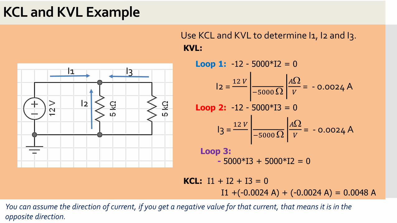
Use KCL and KVL to determine I1, I2 and I3.
KVL:
Loop 1: -12 - 5000*I2 = 0
Loop 2: -12 - 5000*I3 = 0
Loop 3: - 5000*I3 + 5000*I2 = 0
KCL: I1 + I2 + I3 = 0
I2 = 12 𝑉
−5000
𝐴𝑉
= - 0.0024 A
I1 +(-0.0024 A) + (-0.0024 A) = 0.0048 A
You can assume the direction of current, if you get a negative value for that current, that means it is in the opposite direction.
I3 = 12 𝑉
−5000
𝐴𝑉
= - 0.0024 A
I1
I2
I3
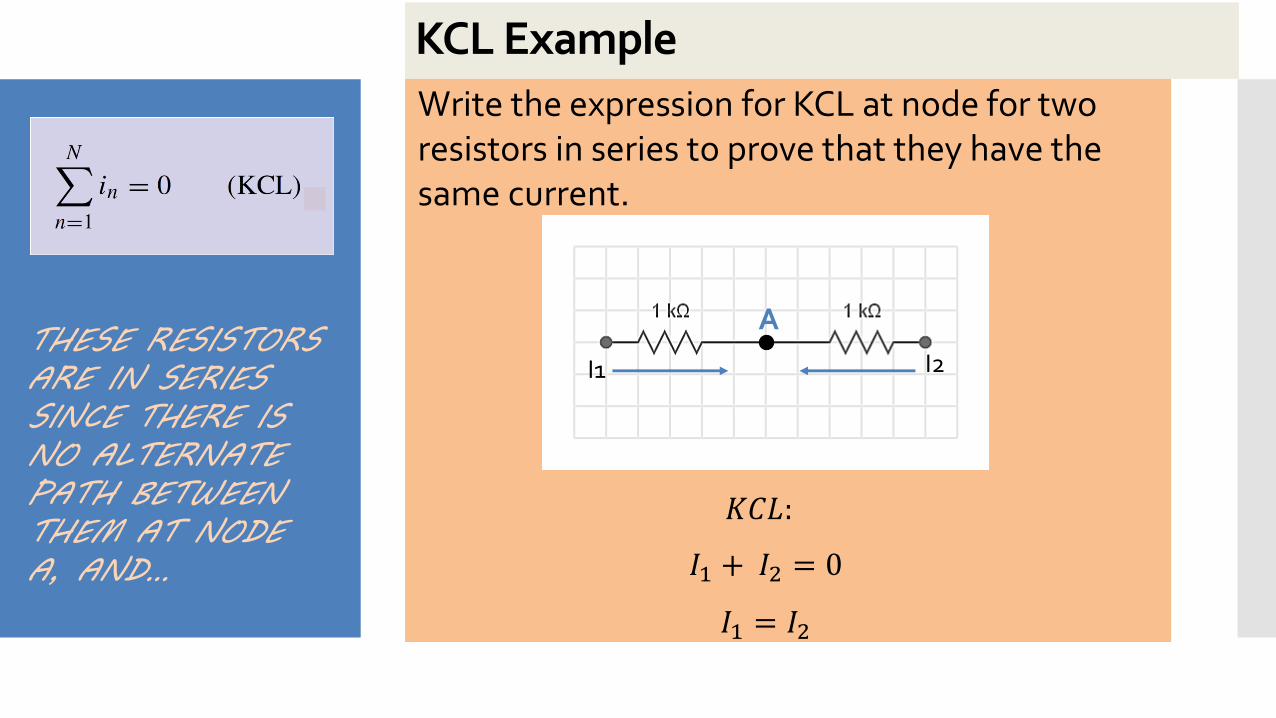
xxKCL Example
Write the expression for KCL at node for two resistors in series to prove that they have the same current.
I1 I2
A
𝐾𝐶𝐿:
𝐼1 + 𝐼2 = 0
𝐼1 = 𝐼2
THESE RESISTORS ARE IN SERIES SINCE THERE IS NO ALTERNATE PATH BETWEEN THEM AT NODE A, AND…
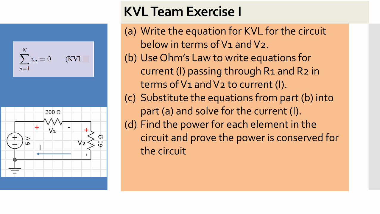
xxKVL Team Exercise I
(a) Write the equation for KVL for the circuit below in terms of V1 and V2.
(b) Use Ohm’s Law to write equations for current (I) passing through R1 and R2 in terms of V1 and V2 to current (I).
(c) Substitute the equations from part (b) into part (a) and solve for the current (I).
(d) Find the power for each element in the circuit and prove the power is conserved for the circuit I
V1
V2
+ - +-
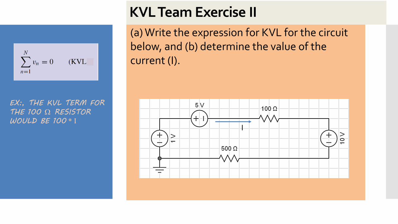
xxKVL Team Exercise II
(a) Write the expression for KVL for the circuit below, and (b) determine the value of the current (I).
I
EX:, THE KVL TERM FOR
THE 100 RESISTOR
WOULD BE 100 * I
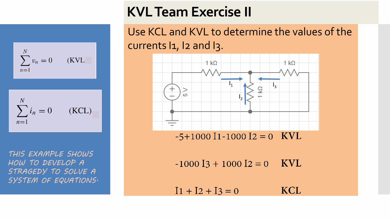
xxKVL Team Exercise II
Use KCL and KVL to determine the values of the currents I1, I2 and I3.
THIS EXAMPLE SHOWS
HOW TO DEVELOP A
STRAGEDY TO SOLVE A
SYSTEM OF EQUATIONS.
I1
I2
I3
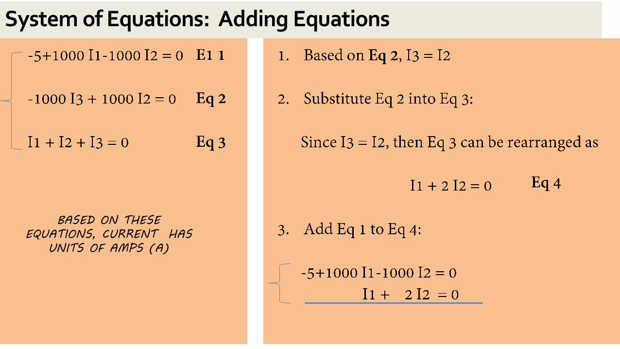
System of Equations: Adding Equations
BASED ON THESE
EQUATIONS, CURRENT HAS
UNITS OF AMPS (A)
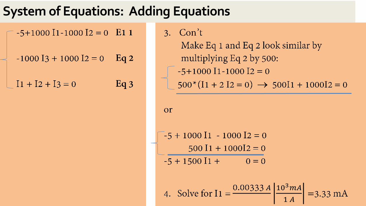
System of Equations: Adding Equations
𝐴 103𝑚𝐴
1 𝐴=
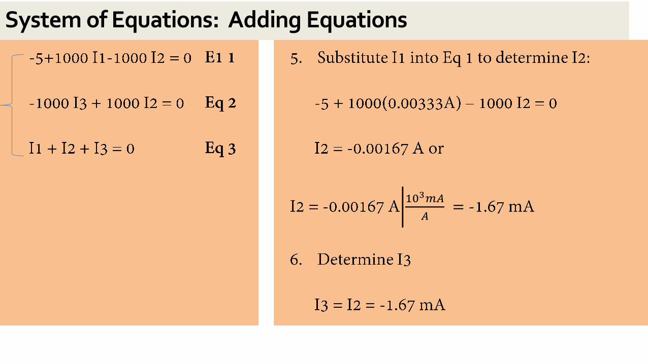
System of Equations: Adding Equations
103𝑚𝐴
𝐴=
System of Equations: Adding Equations
•
When have circuits with AC signals, can analyze with
Bode Plot
(Magnitude vs Frequency)
Example: Filters
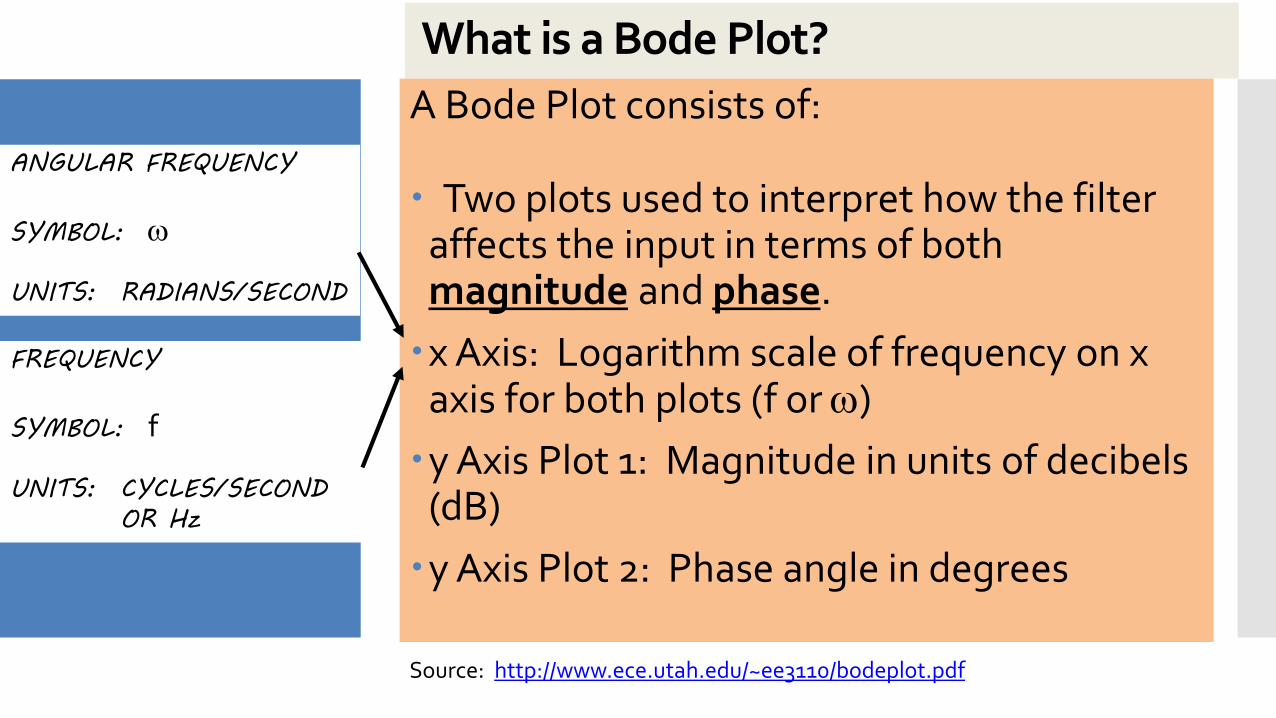
What is a Bode Plot?
A Bode Plot consists of:
Two plots used to interpret how the filter affects the input in terms of both magnitude and phase.
x Axis: Logarithm scale of frequency on x axis for both plots (f or )
y Axis Plot 1: Magnitude in units of decibels (dB)
y Axis Plot 2: Phase angle in degrees
Source: http://www.ece.utah.edu/~ee3110/bodeplot.pdf
ANGULAR FREQUENCY
SYMBOL:
UNITS: RADIANS/SECOND
FREQUENCY
SYMBOL: f
UNITS: CYCLES/SECOND
OR Hz
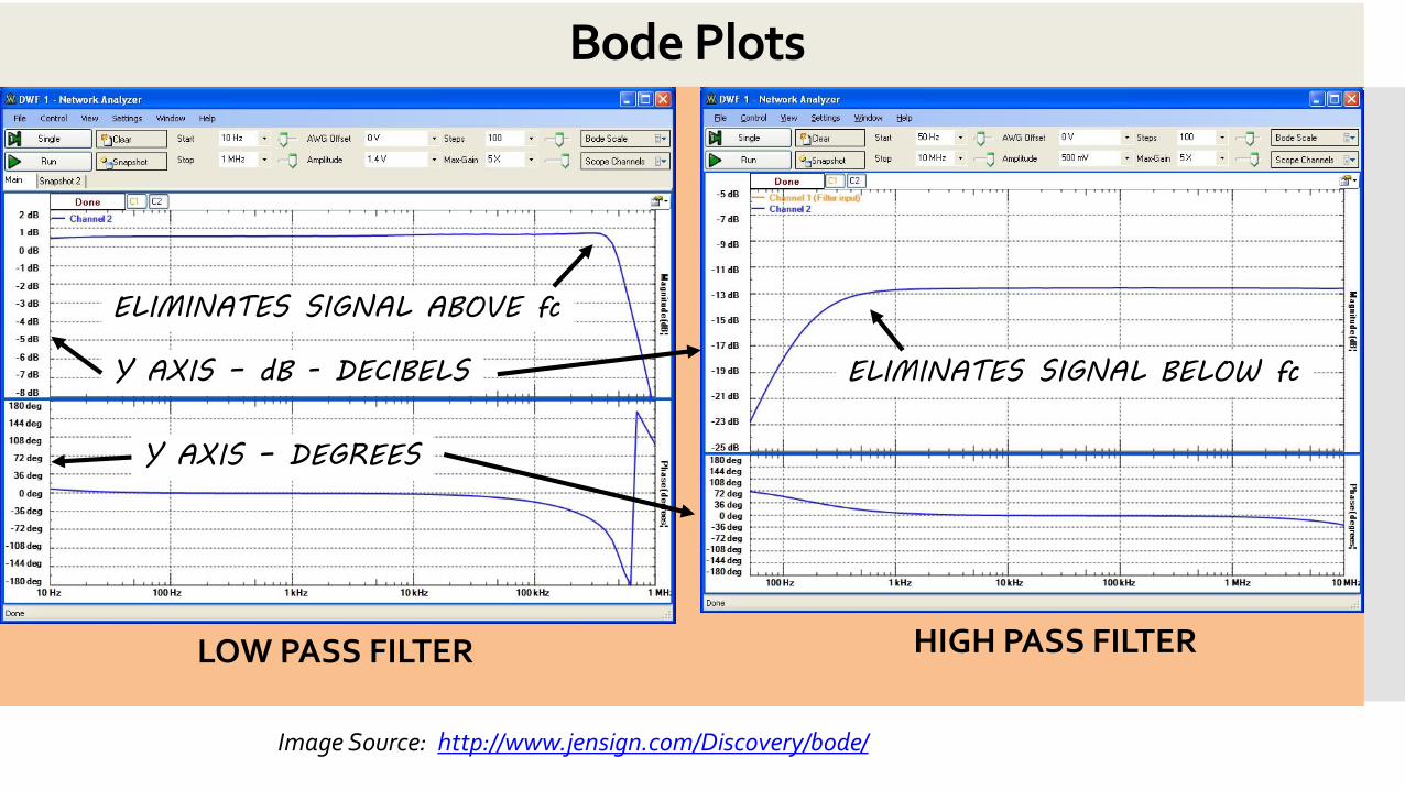
Bode Plots
Image Source: http://www.jensign.com/Discovery/bode/
LOW PASS FILTER HIGH PASS FILTER
ELIMINATES SIGNAL ABOVE fc
ELIMINATES SIGNAL BELOW fcY AXIS – dB - DECIBELS
Y AXIS – DEGREES
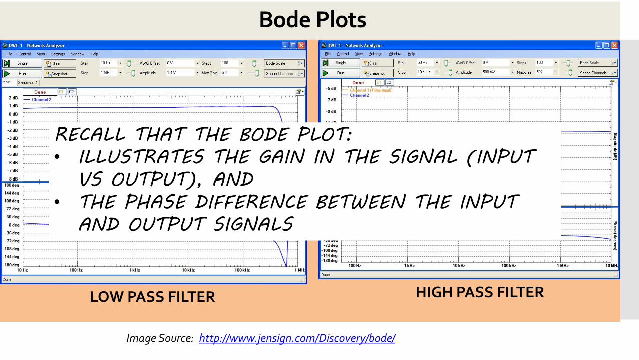
Bode Plots
Image Source: http://www.jensign.com/Discovery/bode/
LOW PASS FILTER HIGH PASS FILTER
RECALL THAT THE BODE PLOT:
• ILLUSTRATES THE GAIN IN THE SIGNAL (INPUT
VS OUTPUT), AND
• THE PHASE DIFFERENCE BETWEEN THE INPUT
AND OUTPUT SIGNALS
Bode Plots
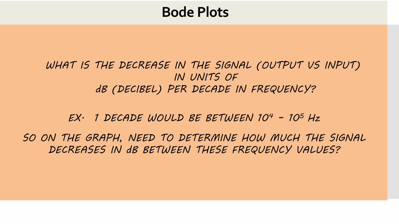
WHAT IS THE DECREASE IN THE SIGNAL (OUTPUT VS INPUT)
IN UNITS OF
dB (DECIBEL) PER DECADE IN FREQUENCY?
EX. 1 DECADE WOULD BE BETWEEN 104 – 105 Hz
SO ON THE GRAPH, NEED TO DETERMINE HOW MUCH THE SIGNAL
DECREASES IN dB BETWEEN THESE FREQUENCY VALUES?
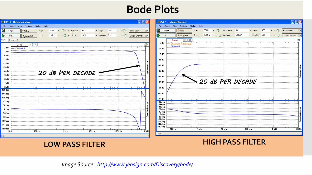
Bode Plots
Image Source: http://www.jensign.com/Discovery/bode/
LOW PASS FILTER HIGH PASS FILTER
20 dB PER DECADE
20 dB PER DECADE
Homework-due 3/6 (Najera), due 3/9 (Quinones)
P17 and P18SUCCESS POINTS:
• TRY EXPLAINING HOW
A BODE PLOT WORKS
TO A TEAM MEMBER,
AND THEN HAVE THEM
EXPLAIN IT TO YOU.
What’s Next in Week 8?
Will introduce…
LAB• Module IV: EKG Sensor
LECTURE • System of Equations – Cramer’s Rule
• KCL and KVL
• Active Component Op-Amp Theory
Please bring laptops to all lectures and labs.

Questions?