Embed Size (px)
Citation preview
PLANNING DEPARTMENTTHE GOVERNMENT OF THE HONG KONG SPECIAL ADMINISTRATIVE REGION
HONG KONG PLANNINGSTANDARDS AND GUIDELINES
Chapter
7 UtilityServices
- CONTENTS –
1. Introduction 1
2. Electricity Supply 2
3. Gas Supply 10
4. Telephone Service 12
5. Radio Telecommunications and Broadcasting Services 16
6. Water Supply 17
7. Drainage Services 20
8. Dedicated Utility Reserves 22
9. District Cooling System 22
(November 2019 Edition)
1
UTILITY SERVICES
1. Introduction
1.1 The provision of utility services, is fundamental to modern living. From the
planning point of view, these services are essential components of the basic
infrastructure. The planning of their provisions should be well coordinated and
integrated into the overall planning of new development areas such that a coherent
and aesthetic design can be achieved. Adequate mitigation measures on building
design, screening and landscaping should be incorporated to ensure that the
buildings/structures of the utility installations/services could blend in with their
surroundings and no unacceptable adverse environmental impacts, including
visual impact, would be generated. For specific greenery coverage requirements,
users may refer to Development Bureau Technical Circular (Works) No. 3/2012 –
Site Coverage of Greenery for Government Building Projects or Buildings
Department’s Practice Notes for Authorized Persons, Registered Structural
Engineers and Registered Geotechnical Engineers APP-152 – Sustainable
Building Design Guidelines, where applicable. Where landscaping (including
vertical greening) is required, the size of the site would have to be suitably
adjusted to cater for such requirement.
1.2 This chapter provides planners with the basic information on electricity supply,
gas supply, telephone service, radio telecommunications and broadcasting
services, water supply, drainage services and district cooling system. The
guidelines would help planners understand the requirements of these
services/facilities, and enable them to work with various government departments
and utility companies in the planning of new development areas.
1.3 Where land is required for the provision of utility services, subject to safety and
other necessary requirements, the general principle of maximising land use
efficiency should be pursued in consultation with the relevant
bureaux/departments. In particular, the following factors should be thoroughly
examined during the planning process:
1.3.1 The size of the buildings/structures of the utility installations should be
limited to the minimum possible for meeting the development needs of the
area that the concerned utility installation serves; and
1.3.2 The maximum development potential of the sites identified for the
concerned utility installations should be exploited as far as practicable.
For example, co-location could be considered wherever possible and
subject to compliance with the prevailing safety standards and other
policies.
2
2. Electricity Supply
2.1 General
2.1.1 Electricity supply is currently provided by The Hongkong Electric
Company Limited (HK Electric) (for Hong Kong Island and the
neighbouring islands of Ap Lei Chau and Lamma) and the CLP Power
Hong Kong Limited (CLP Power) (for the whole of Kowloon, the New
Territories and a number of outlying islands including Lantau).
2.1.2 Electricity supply facilities include power generating stations, electric
substations, overhead lines and underground/submarine cables. Only the
latter three items are discussed because power generating stations are
major territorial facilities requiring special investigations on each project.
2.2 Electric Substations
2.2.1 Electricity is transmitted and distributed by different types of electric
substations. The CLP Power network includes extra high voltage (EHV)
substations, bulk infeed substations (BISs), primary substations and
consumer substations. The HK Electric network includes bulk infeed
substations, primary substations and consumer substations. The
substations’ characteristics are discussed below:
(a) Extra High Voltage Substations & Bulk Infeed Substations (Switching
Stations)
In the CLP Power network, the EHV substations receive power from
the power stations or from other EHV substations at 400 kilovolt (kV)
and supply the bulk infeed or primary substations at 132kV. BISs
receive power from EHV substations or other BISs at 132kV and
supply the primary substations at voltages ranging from 33kV to
132kV and consumer substations at 11kV. In The HK Electric
network, BIS receive power from the power stations or from other
BISs at 275kV or 132kV and supply the primary substations at
voltage of 132kV to 275kV.
(b) Primary Substations (Zone Substations)
In general, for the CLP Power network, primary substations receive
electric power at voltage of 33kV up to 132kV and supply all the
11kV loads in the supply area. For The HK Electric network, in
general primary substations receive electric power at voltage of
132kV to 275kV and supply all the 22kV and 11kV loads in the
supply area.
(c) Consumer Substations (Distribution Substations)
Consumer substations for CLP Power network receive power at a
voltage of 11kV and deliver it at 380V. Consumer substations for
The HK Electric network receive power at a voltage of 22kV or
11kV and deliver it at 380V. There are two types of consumer’s
substations:
3
(i) Indoor Type (Transformer Room)
This is normally provided within the consumers’ premises.
(ii) Outdoor Type
This is mainly found in rural development areas and may be
located either inside or outside the consumers’ premises.
2.2.2 Sufficient number of primary substations and BISs are required to meet
all the 22kV and 11kV loads in a supply area. In order to meet the
demand for electricity supply in a new town or re-developed area on time,
it is recommended that the relevant utility company be advised of the
scale of development at an early planning stage. CLP Power or HK
Electric will investigate if demand can be met by the existing primary
substations and BISs, or new ones are required. With respect to the
access, parking and loading/unloading arrangements, Transport
Department should be consulted at an early planning stage. Please refer
to Table 11 of Chapter 8 for parking and loading/unloading requirements.
Guidelines on Provision
2.2.3 Extra High Voltage Substations & Bulk Infeed Substations
(Switching Stations)
(a) These stations should be located near to the pylons of transmission
lines or major transmission cable routes (for BIS) in the vicinity of the supply area and in an area which permits adequate cabling in the access road(s) leading to the substations.
(b) They should be at least 200m away from the nearest fence of any
telephone exchange, radio-communications and broadcasting installations. Additional advice should be obtained from the Director-General of Communications (DG, Office of the Communications Authority (OFCA)).
(c) As a major electric substation will be a major source of noise
nuisance, it should be located away from residential or other sensitive uses wherever possible to minimize any noise problems. If this is not feasible, suitable noise control measures will need to be included in the design of the station (section 4.2.13 of Chapter 9).
(d) The separation from other buildings/structures should be at least 6m.
(e) Except with prior approval of the Director of Fire Services (D of FS),
no domestic units should be provided above substations.
(f) The site requirement for a typical EHV substation (with 6 x 240
MVA (Mega Volt-amp), 400kV transformers) is about 6 500m2
(100m x 65m). Free access via a carriageway of width not less than
7.3m is required and the gradient should not exceed 1 in 12. These
figures are for reference only as each site reservation is subject to
detailed examination. Additional advice should be obtained from the
Director of Electrical and Mechanical Services (DEMS).
4
(g) The site requirement for a typical BIS in the CLP Power network
(with 4 x 50 MVA, 132/11kV transformers, and 132kV switchboard)
is about 2 870m2 (70m x 41m). In The HK Electric network, the site
requirement for a typical BIS is between 1 504m2 (32m x 47m for a
switching station at 275/132kV level) and 2 550m2 (30m x 85m for
a switching station at 275/132kV level with 2 x 300MVA
275/132kV transformers). Free access via a carriageway of not
less than 7.3m wide and with a gradient not exceeding 1 in 10 is
required. These figures are again for reference only and individual
site is subject to detailed assessment on a case by case basis.
Additional advice can be obtained from the DEMS.
2.2.4 Primary Substations (Zone Substations)
(a) They should be located as near as possible to the supply area and
should be adjacent to more than one road to allow for adequate
cabling requirement.
(b) They should be at least 200m away from the nearest fence of any
telephone exchange, radio-communications and broadcasting
installations. Additional advice can be obtained from the DG,
OFCA.
(c) Except with prior approval of the D of FS, no domestic units should
be provided above the substation.
(d) The site requirement for a typical primary substation in the CLP
Power network (with 4 x 50 MVA, 132/11kV transformers, 132kV
RMUs and 80 x 11kV switchgear panels) is about 1 705m2 (55m x
31m). The site requirement for a typical primary substation in The HK
Electric network, with 4 x 60 MVA, 275 or 132kV transformers is
about 1 600m2 (40m x 40m). The depth of the building should be
increased by 11m for each additional transformer to be installed. Free
access via a carriageway of not less than 7.3m wide with a gradient
not exceeding 1 in 10 is required. The figures are again for reference
only. Additional advice can be obtained from the DEMS.
2.2.5 Consumer Substations (Distribution Substations)
(a) Indoor Type (Transformer Room)
As this is normally provided within the consumer’s premises, the
siting of the facility would be taken up with individual developer
with the power utilities concerned.
(b) Outdoor Type
(i) It should be located as near as possible to the area it serves.
(ii) Adjacent buildings or structures should have a minimum fire
resistance rating of 2 hours failing which a physical separation
of at least 3m should be allowed for.
5
(c) The typical substation size for housing a 1.5 MVA, 22kV or 11kV
transformer and associated control gear is 30.25m2 (5.5m x 5.5m)
for outdoor type and 51m2 (8.5m x 6m) for indoor type.
(d) Access road with a width of not less than 3m is required.
2.3 Overhead Transmission Lines
Guidelines on Provision
2.3.1 The location of new pylons and overhead transmission lines (OHL)
should not be permitted to dictate the pattern of future land use or to
sterilize land which has a good development potential. If the land is
required for development, the existing transmission lines, unless part of
an approved scheme which is the subject of an order under the Electricity
Networks (Statutory Easements) Ordinance, may have to be relaid
underground or re-routed. However, the high cost involved in diversion
should be given due consideration.
2.3.2 They should not be erected in existing developed areas, areas having
substantial development potential, and public open space, as far as
practicable. Except in very special circumstances, environmentally
sensitive areas such as Sites of Special Scientific Interest (SSSI),
conservation areas and country parks should also be avoided.
2.3.3 Early consultation with the concerned departments at the planning stage
is essential, particularly on matters relating to locations of pylons and
OHLs. For extra high voltage transmission lines e.g. 400 kV, detailed site
search reports with full justifications should be prepared for
consideration of relevant departments.
Environmental Considerations
2.3.4 When the erection of permanent OHLs and pylons is planned, a prudent
approach should be adopted taking into account the following principles
and environmental considerations:
(a) They should be routed to avoid as far as practicable, residential areas
and environmentally sensitive areas such as SSSI, conservation areas,
country parks, ridgelines or locations which will seriously affect the
view from major residential developments.
(b) The location and design of pylons should minimize the ecological
and visual impacts on the landscape and nearby residential
developments.
(c) Damage to existing vegetation through the erection of pylons should
be minimized and landscape reinstatement should be undertaken
where necessary.
6
(d) Where permanent overhead lines in environmentally sensitive areas
covered by para. (a) cannot be avoided, the Director of Agriculture
and Fisheries (where the development is within a country park), the
Director of Planning and the Director of Environmental Protection
should be consulted to determine the appropriate type of planning
and environmental assessment studies to be undertaken and whether
mitigation measures should be implemented to minimize any
adverse impacts identified. The Director of Home Affairs should
also be consulted on the appropriate level and means of public
consultation which may need to be carried out.
(e) For OHLs which are considered as Designated Projects(1) under the
Environmental Impact Assessment Ordinance (EIA Ordinance), the
statutory EIA process must be followed and environmental permits
are required for their construction and operation.
Safety Considerations
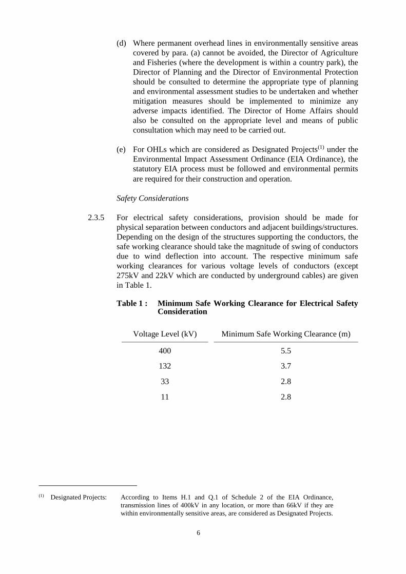
2.3.5 For electrical safety considerations, provision should be made for
physical separation between conductors and adjacent buildings/structures.
Depending on the design of the structures supporting the conductors, the
safe working clearance should take the magnitude of swing of conductors
due to wind deflection into account. The respective minimum safe
working clearances for various voltage levels of conductors (except
275kV and 22kV which are conducted by underground cables) are given
in Table 1.
Table 1 : Minimum Safe Working Clearance for Electrical Safety
Consideration
Voltage Level (kV) Minimum Safe Working Clearance (m)
400 5.5
132 3.7
33 2.8
11 2.8
(1) Designated Projects: According to Items H.1 and Q.1 of Schedule 2 of the EIA Ordinance,
transmission lines of 400kV in any location, or more than 66kV if they are
within environmentally sensitive areas, are considered as Designated Projects.
7
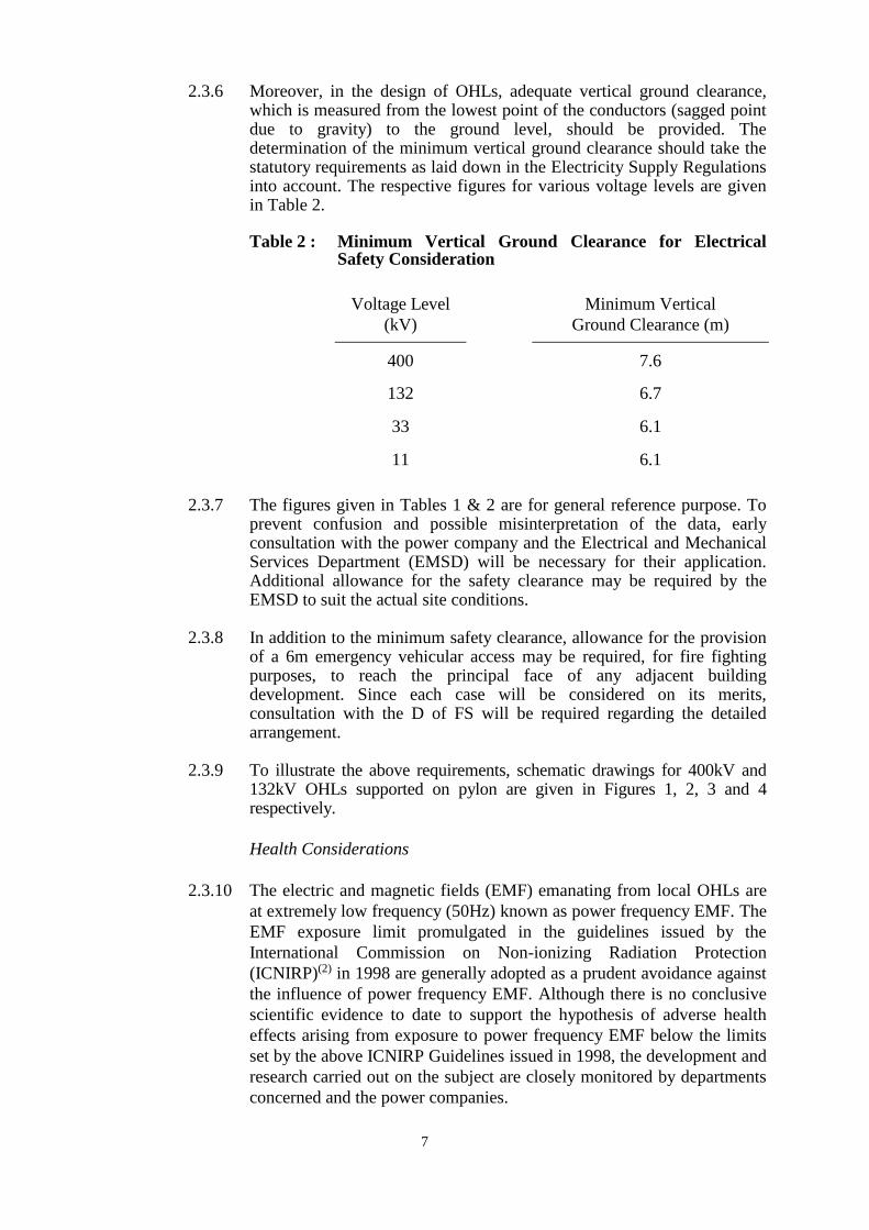
2.3.6 Moreover, in the design of OHLs, adequate vertical ground clearance, which is measured from the lowest point of the conductors (sagged point due to gravity) to the ground level, should be provided. The determination of the minimum vertical ground clearance should take the statutory requirements as laid down in the Electricity Supply Regulations into account. The respective figures for various voltage levels are given in Table 2.
Table 2 : Minimum Vertical Ground Clearance for Electrical
Safety Consideration
Voltage Level
(kV)
Minimum Vertical
Ground Clearance (m)
400 7.6
132 6.7
33 6.1
11 6.1
2.3.7 The figures given in Tables 1 & 2 are for general reference purpose. To
prevent confusion and possible misinterpretation of the data, early consultation with the power company and the Electrical and Mechanical Services Department (EMSD) will be necessary for their application. Additional allowance for the safety clearance may be required by the EMSD to suit the actual site conditions.
2.3.8 In addition to the minimum safety clearance, allowance for the provision
of a 6m emergency vehicular access may be required, for fire fighting purposes, to reach the principal face of any adjacent building development. Since each case will be considered on its merits, consultation with the D of FS will be required regarding the detailed arrangement.
2.3.9 To illustrate the above requirements, schematic drawings for 400kV and
132kV OHLs supported on pylon are given in Figures 1, 2, 3 and 4 respectively.
Health Considerations
2.3.10 The electric and magnetic fields (EMF) emanating from local OHLs are
at extremely low frequency (50Hz) known as power frequency EMF. The
EMF exposure limit promulgated in the guidelines issued by the
International Commission on Non-ionizing Radiation Protection
(ICNIRP)(2) in 1998 are generally adopted as a prudent avoidance against
the influence of power frequency EMF. Although there is no conclusive
scientific evidence to date to support the hypothesis of adverse health
effects arising from exposure to power frequency EMF below the limits
set by the above ICNIRP Guidelines issued in 1998, the development and
research carried out on the subject are closely monitored by departments
concerned and the power companies.
8
2.3.11 In line with the guidelines issued by ICNIRP in 1998, the following
standards on the continuous public exposure limits for power frequency
electric and magnetic fields are recommended to the power companies by
EMSD when the erection of permanent overhead transmission lines is
planned:
(a) The electric field strength(3) should not exceed 5kV per metre
(r.m.s.); and
(b) The magnetic flux density(4) should not exceed 0.1 millitesla (r.m.s.)
(i.e. 100 microteslas, r.m.s.).
The power companies should seek further advice from the EMSD at the
design and planning stages of the overhead lines concerned.
2.3.12 In general, the physical separation provided by the preferred working
corridor (para. 2.3.13 refers) has made allowance for the above
consideration. However, at the early planning stage of the OHLs, the
power company concerned should provide the necessary information to
the EMSD for consideration.
Preferred Working Corridor of Overhead Transmission Lines
2.3.13 For route protection and to provide sufficient space for pylon erection,
operation, inspection, maintenance, repair, renewal and removal of the
equipment, a “preferred working corridor” (as shown in Figure 1 and
Figure 3) following the alignment of the OHLs, will be required for
general planning purpose. In the case of pole lines, in addition to the
“preferred working corridor”, a “preferred working circle” is required for
pole erection as shown in Figure 5 and Figure 6.
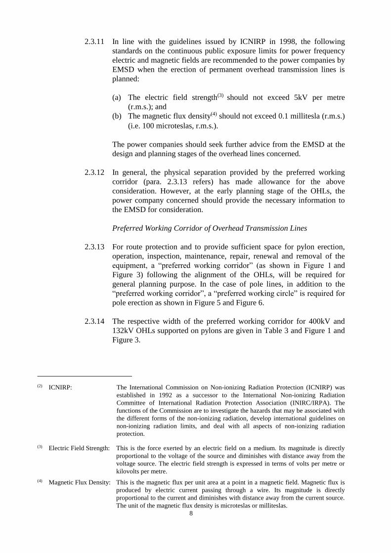
2.3.14 The respective width of the preferred working corridor for 400kV and
132kV OHLs supported on pylons are given in Table 3 and Figure 1 and
Figure 3.
(2) ICNIRP: The International Commission on Non-ionizing Radiation Protection (ICNIRP) was
established in 1992 as a successor to the International Non-ionizing Radiation
Committee of International Radiation Protection Association (INIRC/IRPA). The
functions of the Commission are to investigate the hazards that may be associated with
the different forms of the non-ionizing radiation, develop international guidelines on
non-ionizing radiation limits, and deal with all aspects of non-ionizing radiation
protection.
(3) Electric Field Strength: This is the force exerted by an electric field on a medium. Its magnitude is directly
proportional to the voltage of the source and diminishes with distance away from the
voltage source. The electric field strength is expressed in terms of volts per metre or
kilovolts per metre.
(4) Magnetic Flux Density: This is the magnetic flux per unit area at a point in a magnetic field. Magnetic flux is
produced by electric current passing through a wire. Its magnitude is directly
proportional to the current and diminishes with distance away from the current source.
The unit of the magnetic flux density is microteslas or milliteslas.
9
Table 3 : Preferred Working Corridor for 400kV and 132kV
OHLs supported on Pylon
Voltage Level (kV) Width of the Preferred Working
Corridor (m)
400 50
132 36
Note: Some of the 132kV OHLs are supported on pylons
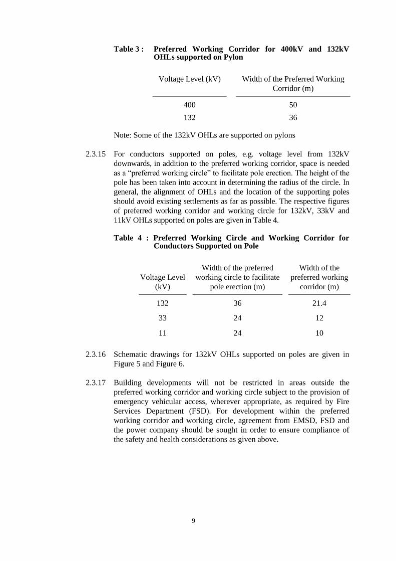
2.3.15 For conductors supported on poles, e.g. voltage level from 132kV
downwards, in addition to the preferred working corridor, space is needed
as a “preferred working circle” to facilitate pole erection. The height of the
pole has been taken into account in determining the radius of the circle. In
general, the alignment of OHLs and the location of the supporting poles
should avoid existing settlements as far as possible. The respective figures
of preferred working corridor and working circle for 132kV, 33kV and
11kV OHLs supported on poles are given in Table 4.
Table 4 : Preferred Working Circle and Working Corridor for
Conductors Supported on Pole
Voltage Level
(kV)
Width of the preferred
working circle to facilitate
pole erection (m)
Width of the
preferred working
corridor (m)
132 36 21.4
33 24 12
11
11
24 10
2.3.16 Schematic drawings for 132kV OHLs supported on poles are given in
Figure 5 and Figure 6.
2.3.17 Building developments will not be restricted in areas outside the
preferred working corridor and working circle subject to the provision of
emergency vehicular access, wherever appropriate, as required by Fire
Services Department (FSD). For development within the preferred
working corridor and working circle, agreement from EMSD, FSD and
the power company should be sought in order to ensure compliance of
the safety and health considerations as given above.
10
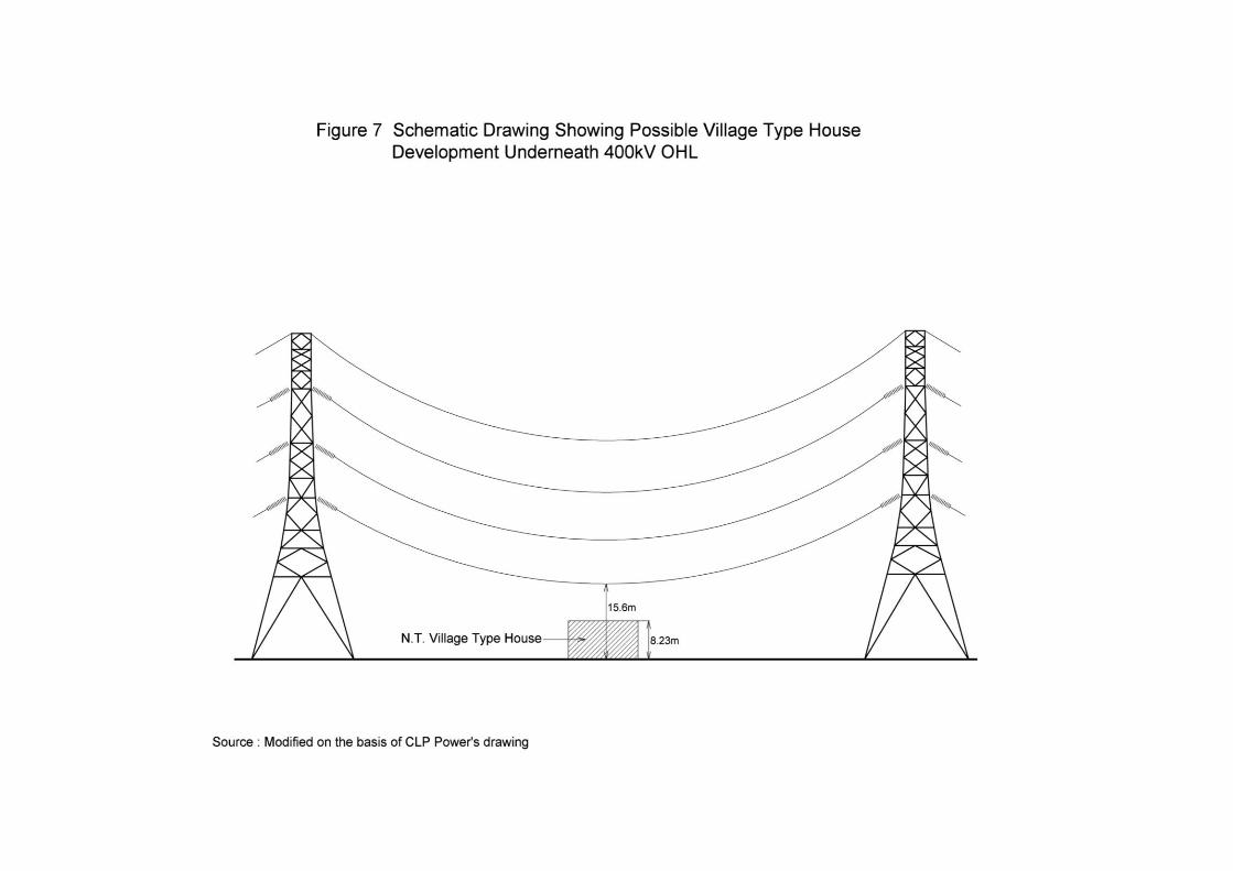
2.3.18 For example, New Territories Exempted House/village house
development underneath 400kV OHLs will be possible provided that the
height of the conductors (sagged portion) is designed not less than 15.6m
above the ground level. This clearance makes allowance for the
maximum height of the village house (8.23m) and the average height of
an antenna (1.87m) such that the minimum safety clearance of 5.5m
between antenna and the 400kV conductors is maintained. However,
agreement must be obtained from EMSD, FSD and the power company
before the commencement of any development or building works. An
illustrative sketch is given in Figure 7.
2.3.19 Notwithstanding the above, the Land Authority should also notify the
power company concerned of any development (permanent or temporary)
that is proposed within a distance of 45m from overhead transmission
lines.
Separation from Telecommunication Lines on support
2.3.20 The alignment of the OHL should be separated from other
telecommunication lines e.g. telephone, on support. Reference should be
made to the “Code of Practice - Protection of Communication Networks
From Electrical Power Distribution” issued by the DG, OFCA.
2.4 Underground/Submarine Cables
2.4.1 Cables are normally laid directly underground or under seabed, subject to
permission from the Highways Department and/or the Lands Department
and other appropriate authorities if required and compliance with relevant
Ordinances.
2.4.2 Minimum separation between power cables and telephone cables is 0.3m
wherever practicable. Details can be obtained from the DG, OFCA.
3. Gas Supply
3.1 General
3.1.1 The Government’s policy is to ensure, as far as possible, the provision of a
piped gas supply to domestic consumers, particularly to new building
developments, as a means of discouraging the future growth of liquefied
petroleum gas cylinders. In this regard, a piped gas supply in the form of
town/natural gas or from a bulk liquefied petroleum gas (LPG) storage
installation should be planned for all new developments.
3.1.2 The Gas Safety Ordinance (Cap. 51) and its subsidiary regulations which
became effective on the 1st April 1991 must be complied with when a gas
supply is considered.
11
3.2 Piped Gas Supply
3.2.1 A piped gas supply can be made available by:
(a) the provision of town/natural gas through the conventional reticulated
supply system of the Hong Kong and China Gas Co. Ltd.;
(b) the supply of LPG from a centralized LPG storage facility located
nearby or within the development area to be served. The size of the
development area can range from a large housing estate such as Mei
Foo Sun Chuen to a single house; and
(c) a form of substitute town/natural gas supplied by the Hong Kong
and China Gas Co. Ltd. through a reticulated supply system from
temporary LPG/air mix plants. When town/natural gas becomes
available, the LPG/air mix plant would cease operation. The
town/natural gas would then be supplied to consumers through the
reticulated supply system in existence.
3.2.2 The advice of either the Hong Kong and China Gas Co. Ltd. (for
town/natural gas) or the potential LPG supplier (for LPG) should be
sought at the earliest possible stage in the design of the development or
redevelopment proposals.
3.3 Guidelines on Provision
Town/Natural Gas
3.3.1 The production, storage and distribution of town/natural gas require the
building of gas works, gas holder stations, pressure reduction equipment
and a pigging system ranging from high to low supply pressures. Gas
works and gas holder stations are very specialized facilities and need to be
dealt with on an individual basis, taking account of hazard assessments.
Gas pressure reduction station installations are required for reducing the
pressure from a higher pressure pipeline system to a lower pressure system.
The site area required for installing the pressure reduction equipment is
dependent on operation requirements and can vary from 12m2 to 2 000m2.
Generally, the supply pipes should be laid underground, however, due to
various technical reasons, alternative installation methods may be
considered. As for the location and safety separation distance
requirement for pipelines, the EMSD (Gas Standards Office) is the
authority to advise. No supply pipes should be accommodated in a
highway structure which is a sole access or carries a strategic route.
However, consideration should be given to waive the constraint when
there is no alternative route. Close liaison between the Highways
Department (HyD) and the gas company at the early planning stage will
be necessary in identifying an acceptable routing arrangement.
12
Centralized LPG supply Installations
3.3.2 A permanent site located within the development areas being served is
required. However, the size of the storage area required, the safety
distances needed, and the laying of pipes would be subject to advice of
the EMSD (Gas Standards Office). As a general rule, the installations
should be secure, sited in a well ventilated area and accessible by
vehicles for replenishment and emergency service.
Substitute Town/Natural Gas
3.3.3 A temporary LPG/Air mix plant could be located in the vicinity of the
township or development being served but not necessarily immediately
adjacent to it as substitute town/natural gas can be supplied over long
distances by underground pipelines. However, the plant should be located
in a well ventilated area where other utility services, such as water and
electricity are available and accessible by vehicles for replenishment and
emergency service. Whilst the gas production installation itself is
temporary, the reticulated supply system is permanent and could be
connected with the town/natural gas supply subsequently. The location
and site area of a LPG/air mix installation will depend on the number of
consumers to be served. The number of consumers determines the
quantity of LPG to be stored, vaporization and air-mix plant requirements;
these in turn determine the safety distances needed between the
installation and adjacent buildings and fixed points of ignition. The
advice from the EMSD (Gas Standards Office) should be sought.
Hazard Assessments
3.3.4 Hazard assessments for gas works, gas holder stations and LPG
installations form an integral part of the project evaluation and additional
safety measures may need to be incorporated into the design and/or
operations of the installations to ensure that the risk posed to the general
public is minimized. Reference should be made to the risk guidelines
in Chapter 12 and procedures laid down by the Coordinating
Committee on Land Use Planning and Control related to Potentially
Hazardous Installations should be followed. The EMSD (Gas Standards
Office) is the authority for such hazard assessments. The Land
Authority shall notify the gas company concerned of any development
(permanent or temporary) that is proposed within a distance of 3m either
side of a high pressure (up to 35 bar) gas pipelines.
4. Telephone Service
4.1 General
4.1.1 Local fixed telephone service is one of the local fixed telecommunications
network services (FTNS). The local FTNS licensees are PCCW-HKT
Telephone Limited (PCCW-HKT), Hutchison Global Crossing Limited
13
(HGC), New T&T Hong Kong Limited (New T&T) and New World
Telephone Limited (NWT).
4.1.2 International telephone service is one of the external telecommunications
services (ETS). The FTNS licences of PCCW-HKT, HGC, New T&T
and NWT have been amended to provide non-exclusive ETS. In mid-
2001, about 200 companies were awarded the Public Non-exclusive
Telecommunications Services Licence to provide ETS.
4.2 Telephone Network
4.2.1 A telephone network comprises subscriber premise apparatus, subscriber
lines, telephone exchanges and junction circuits.
4.2.2 Each subscriber premise apparatus is connected by a pair of subscriber
lines to a local telephone exchange where switching and connection are
conducted between two subscribers.
4.2.3 From the input telephone number, the switching equipment in the
telephone exchange will locate the called party who may be in the same
exchange or in another exchange.
4.2.4 The communication links provided between exchanges are junction
circuits which are to carry inter-exchange calls. The junction circuits
consist of Telephone Cables Systems and Radio Telecommunication
Systems.
4.3 Telephone Exchanges
4.3.1 Generally, all telephone exchanges accommodate local exchange
equipment. In some telephone exchanges, there may be other types of
exchange equipment serving different functions of tandem, toll or other
services. Local and tandem exchanges are more common.
(a) Local Exchange
Local exchange is where subscriber lines are terminated. Each
local exchange serves its nearby communities. Depending on
geographical situations, the density of population and business, the
number of subscriber lines served by a local exchange may vary
from a few hundreds to 120 000. There are about 90 local
exchanges in mid-2001.
(b) Tandem Exchange
Tandem exchanges are employed to relay telephone calls between
local exchanges. They are usually co-sited with local exchanges.
14
4.4 Guidelines on Provision
4.4.1 In order to meet demand for telephone service in a new town or
redeveloped area on time, the FTNS operators should be advised of the
scale of development at an early planning stage. The FTNS operators will
investigate if telephone service can be provided from an existing local
exchange, by any other methods or a new exchange is required.
Telephone Exchange
4.4.2 No direct standard can be derived for land reservation as the size of site
varies with a number of factors such as the number of lines and type of
switching equipment. However, the following can be adopted as general
guidelines:
(a) For local exchanges in rural areas with less than 10 000 lines, a site
area of about 500m2 is required.
(b) For local exchanges in urban areas with 20 000 to 60 000 lines, a
site area between 1 000m2 to 1 500m2 is required.
(c) For local exchange in urban areas with up to 120 000 lines, or
combined local/tandem exchanges or telephone exchanges
complexes (operator center, office, computer room, exchange), a site
area ranging from 1 500m2 to 2 000m2 is required.
4.4.3 In rural areas, small telephone exchanges with land reserved for minor
expansion are preferred to large ones so as to preserve the rural amenity.
4.4.4 In urban areas, telephone exchanges are normally installed in specially
designed multi-storey buildings. However, in exceptional cases, they can
be accommodated within other types of buildings with the specific
telephone exchange requirements incorporated into the building design.
4.4.5 Exchanges need to be located as near as possible to the centre of
telephone service demand for efficiency and economic reasons.
4.4.6 Exchanges should be provided with easy access to main roads for external
cable plant construction and equipment delivery. A corner site abutting
two to three roads in rectangular shape is preferable for better cable duct
laying and equipment layout. With respect to the access, parking and
loading/unloading arrangements, Transport Department should be
consulted at an early planning stage.
4.4.7 In general, the site should be available for the construction of the
telephone exchange about 2.5 years before the completion of the first
phase of major developments. This is to ensure availability of telephone
service to the users of the initial phases of development.
15
4.4.8 Exchanges should be sited at least 200m from any power generating
station, bulk in feed substation or primary substation (i.e. at 132kV or
higher voltage) to avoid the risk of rise-of-earth potential and electrical
interference which can be very critical to the safety of the operation
personnel and to the sophisticated electronic telecommunication
installations in the exchanges.
4.4.9 Telephone exchanges should be sited away from an electrified rail system,
large box culvert, mullah and cable tunnel so as to avoid blockage to the
multiway telephone cable lead-in ducts. The separation distance should
be assessed on individual basis. FTNS operators should be consulted at
an early planning stage.
4.4.10 Telephone exchanges should be located away from any dangerous goods
installation such as petrol filling station and inflammable material store
to avoid the risk of fire or explosion. Moreover, they should not be
located near rivers or lakes to avoid flooding problems.
Telephone Cables
4.4.11 Telephone cables should normally be laid in underground ducts except
where prohibited by other factors such as crossing bridges, rivers and
nullahs; temporary cable provision for construction sites; provision of
small quantity of overhead cable in rural area due to economical reason
and provision of overhead cable over privately-owned land.
4.4.12 Telephone cables should be placed as far as possible away from power
generating or transformer stations except those feeding the stations. Such
telephone cables may require special protection.
4.4.13 Telephone cables should be separated as far as possible from power
cables. The normal separation should be at least 0.3m. For details, the
“Code of Practice - Protection of Communication Network From
Electrical Power Distribution” issued by DG, OFCA should be referred
to.
4.4.14 Telephone cables should be laid as far as possible away from electrified
rail systems. In Light Rail Transit System, a minimum separating
distance of 2.5m from the nearest rail is required. For Kowloon Canton
Railway System, a minimum distance of 300m is required.
4.4.15 In principle, highway utilities reserves should be used to carry telephone
cable ducts. Consultation with FTNS operators is required in an early
planning stage of the highway.
16
Radio Telecommunication Systems
4.4.16 Microwave Radio Communication Systems may be used to connect urban
areas to the non-urban areas where the use of telephone cables is
impracticable or not economical.
4.4.17 They are normally installed on roof top of telephone exchange buildings.
However, in exceptional cases, they can also be installed in mobile
containers located in the vicinity of the telephone exchange, or installed
by other methods.
4.4.18 In principle, the aerial equipment needs to be situated in a location which
can maintain a clear line-of-sight with the counterpart aerial equipment
located at another telephone exchange building or a hill-top radio station.
5. Radio Telecommunications and Broadcasting Services
5.1 General
5.1.1 The wide range of facilities within this category makes it impossible to
lay down standard land requirements, and they have to be considered on a
case-by-case basis. As a general principle, sharing use of existing hill
top sites would be encouraged.
5.1.2 For radio telecommunications services and broadcasting services
delivered by wireless means, OFCA would strive to avoid, as far as
possible, the use of virgin hill-top sites, especially the sensitive or high
landscape value areas within such sites. In case a new development area
cannot be served adequately by radio telecommunications or broadcasting
stations installed at the existing hill-top sites, virgin hill-top sites will be
necessary. Under such circumstances, the radio telecommunications or
broadcasting stations should be located close to the existing access roads
as far as possible so as to minimize the need of constructing haul roads
which may have adverse impacts to the environment. Given that the
process of an application for a virgin hill-top site requires the
coordination of multiple government departments, planning for radio
telecommunications and wireless broadcasting services in a new
development area will have to start at the early planning stage and the
lead time may take as long as 36 months.
5.2 Guidelines on Provision of Hill-top Facilities
5.2.1 The location and design of telecommunications and broadcasting
structures (e.g. buildings and towers) should be determined with
reference to the “Procedure for Applications to Use or Develop Hill-top
and Rural Sites for Radio-telecommunications Systems” which is issued
by OFCA and is available upon request.
17
6. Water Supply
6.1 General
6.1.1 Approximately 70-80% of the fresh water consumed in Hong Kong is
obtained from Mainland via the agreement made with the Guangdong
Authority. The remaining 20-30% is collected from gazetted water
gathering grounds which occupy about one-third of the total area of the
territory.
6.1.2 The principal land requirements for fresh water supply are those for storage
reservoirs and water gathering grounds, water conduits, water treatment
works, pumping stations, service reservoirs, depots, workshops and
offices. Land is also required for conduits, pumping stations, and service
reservoirs for the supply of salt water for flushing.
6.1.3 Land in water gathering grounds needs not be used exclusively for water
supply and there are agreed policies by which other compatible uses may
be permitted. Planning of development or projects to be located inside or
near the water gathering grounds should follow guidelines laid down by
Water Supplies Department (WSD). These are set out in the “Working
Party Report on Land Use and Development in Catchment Areas”.
Amongst such other uses are notably Country Parks, Special Areas or Sites
of Special Scientific Interest, and other recreational areas, etc.
6.1.4 The occupation of seafront land by water supply utilities that will result in
environmental and visual impacts should be avoided. Unless justified
on operational grounds, or when there is no better alternative location,
relevant bureaux/departments should keep the footprint of the facility to a
minimum as far as possible, and implement necessary mitigation
measures to reduce impact on the waterfront. Where practicable, relevant
bureaux/departments should also proactively set back boundary of the
facility to provide waterfront passageway for public use.
6.1.5 Roofs of service reservoirs in most cases provide large level surfaces.
Where they are easily accessible from nearby populated areas and are not
required by the WSD for operational reasons, they can be planned for
open spaces, recreation grounds and other compatible uses subject to
proper management and appropriate safeguards. The intention for this
dual use should be agreed with the WSD before designing a service
reservoir.
18
6.2 Locational Guidelines
6.2.1 Service Reservoirs
(a) Service reservoirs (both fresh water and salt water) should be
located as near as possible to the area they served and, wherever
possible, sited at a level where water can be fed by gravity to the
Supply Zone. The location should avoid, as far as possible, country
parks, prominent seafront areas, special areas and other
environmentally sensitive areas.
(b) Where possible, difficult sites should be avoided so as to minimize
the construction costs. The design of the reservoirs should reduce
adverse visual, landscape, and ecological impacts. Landscape
treatments should be incorporated in the design.
(c) Where alternative sites are available, all of which satisfy waterworks
requirements (construction costs, operation costs, etc.), it is
desirable to choose sites which are more accessible so that the roofs
can be used for recreation.
6.2.2 Pumping Stations
(a) They should normally be located within reasonable proximity to the
source of supply to ensure a positive suction head is available.
(b) Sites for pumping stations should have adequate vehicular access to
facilitate maintenance and transportation of materials and dangerous
goods (disinfectant substances, etc.).
(c) Pumping stations should be located away from residential or other
sensitive uses, wherever possible, to minimize noise problems. If
this is not feasible, suitable control measures will need to be
included in the design of the stations (see also Section 4.2.13 of
Chapter 9). If necessary, landscaping should also be incorporated
to blend in with the surrounding environment.
(d) Salt water pumping stations for intake of seawater should be located
as near as possible to seafront with access to a source of clean sea
water. It is necessary that marine activities and drainage outfalls are
kept away from the sea water intake of the stations. A minimum
clear distance of 100m (i.e. 200m being the total distance of the two
sides from the intake point) is normally required. The footprint of
any salt water pumping stations located by the waterfront should be
kept to a minimum as far as practicable. The environmental and
visual impact of the pumping station on the waterfront should be
reduced through incorporation of suitable mitigation measures, and
the design of the pumping station should integrate with the
adjoining waterfront promenade.
19
6.2.3 Water Treatment Works
(a) For water treatment works classified as Potentially Hazardous
Installation, their locations should comply with the procedures laid
down by the Coordinating Committee on Land Use Planning and
Control related to Potentially Hazardous Installations (CCPHI).
(b) Locations of water treatment works should take account of the
possible environmental impacts arising from sludge discharge, noise
from pumping facilities (see para. 6.2.2 (c) above), and physical
appearance. Any sludge discharge must comply with the established
guidelines for effluent control while suitable landscaping should
also be incorporated, where necessary, to blend in with the
surrounding environment.
6.2.4 Water Mains
(a) Water mains are normally placed underground and routed along
carriageways. Where circumstances permit, they should best be
routed beneath separate reserves, like pedestrian ways or cycle
tracks. Amenity strips should be avoided unless under necessary
circumstances.
(b) Adequate separation of water mains from power cables and other
services should be allowed, wherever practicable.
(c) It is bad engineering practice to route water mains close to the crest
of a slope. All possible steps must be taken to prevent leakage
affecting the stability of the slope. As a general rule, all water
mains should not be placed in a slope nearer to the crest of the slope
than a distance equal to its vertical height. This is a minimum
standard, but each case should be considered on its own merits. In
cases where the proposed development cannot be modified to permit
the siting of water mains outside this crest area, the slope should be
designed to the appropriate factors of safety, taking into account the
effects of possible water leakage. As an alternative, water mains
can be housed within a sealed trench, ducting system or sleeve
drained to a suitable discharge point at a surface drain or natural
stream. The ducting system should be designed with a drainage
capacity equivalent to a pre-determined leakage rate. It is
recommended that discharge from the ducting system be monitored
at six monthly intervals.
20
7. Drainage Services
7.1 General
7.1.1 Drainage services include the provision, operation and maintenance of
foul sewerage, sewage treatment and disposal, and stormwater drainage
infrastructures. Public drainage services are currently provided by the
Drainage Services Department.
7.1.2 The provision of such services, whether for public or private use, shall
conform with the standards and guidelines for environmental planning as
set out in Chapter 9.
7.2 Foul Sewerage System
7.2.1 Sewage should be collected and conveyed in enclosed foul sewers which
should normally be placed underground. Sewerage system should be
designed to minimize odour and septic problems. For operation and
maintenance requirement for septicity control, users may refer to the
relevant Drainage Services Department Practice Notes No. 1/2011 –
Design Checklists on Operation & Maintenance Requirements.
7.2.2 Sewers could be located under the carriageways, footpaths or cycle tracks.
Amenity strips should be avoided unless under necessary circumstances.
If this is not feasible, separate drainage reserves should be provided. The
location and alignment of a sewer should be chosen such that, during the
subsequent maintenance of the sewer, disruption to vehicular and
pedestrian traffic is minimized. Where sewers are placed under
carriageways, they should be located within one traffic lane as far as
possible to minimize disruption to traffic during maintenance. Gravity
sewerage systems should be used as far as possible.
7.3 Stormwater Drainage System
7.3.1 Stormwater may be collected and conveyed either in enclosed drains or
open channels. Section 7.2.2 is also applicable to the planning and design
of enclosed stormwater drains. New drainage channels/systems should
adopt environmental and sustainable design as far as practicable. For
design of drainage infrastructure including green river channels and flood
mitigation/retention measures, users may refer to the relevant Drainage
Services Department Practice Note No. 1/2005 – Guidelines on
Environmental Considerations for River Channel Design.
7.3.2 When choosing the alignment of drainage channels, account should be
taken to minimize disruption to adjacent communities and minimize land
resumption.
21
7.3.3 Supporting facilities such as vehicular access should be provided to
enable proper operation and maintenance of the drainage channels.
Landscaping should be considered and incorporated to blend in with the
environment. Supporting drainage facilities such as channel
embankments may be permitted to be used as amenities or recreational
areas and access roads as waterfront promenades.
7.4 Pumping Stations and Sewage Treatment Works
7.4.1 Sewage treatment works and stormwater and sewage pumping stations
should be designed to minimize noise, odour and visual problems. They
should be located away from residential or other sensitive areas by
providing suitable buffer zones, where possible. If this is not feasible,
suitable abatement measures such as acoustic insulation, odour control and
landscaping should be included in the design of the facilities. If there are
operational needs for the pumping station to be located at prominent
waterfront areas, the footprint should be minimized as far as practicable,
with landscaping and enhancement works carried out to reduce its
environmental and visual impacts. Sewage pumping stations and the
associated rising mains, and sewage treatment works should also be
designed to minimize unintended prolonged retention of sewage and
formation of septic conditions.
7.5 Polder Drainage and Stormwater Pumping Schemes
7.5.1 Polder drainage and stormwater pumping schemes are to render flood
protection to buildings and houses in low-lying areas. The scheme entails
the construction of stormwater pumping station, stormwater storage pond,
and flood protective bund or wall around the buildings and houses and
stormwater storage pond.
7.5.2 Stormwater storage ponds should be located at the lowest areas of the
schemes. They should either be covered or properly fenced off for safety
reasons. Under no circumstances should public access routes be allowed
through the areas of the stormwater storage ponds.
7.6 Drainage Reserves
7.6.1 Unrestricted vehicular access to Drainage Reserves should be provided at
all times. Structures of any kind should generally not be permitted unless
in exceptional circumstances. Besides, planting proposals involving
extensive and deep root plants within Drainage Reserves should seek
Drainage Services Department’s endorsement before implementation.
22
8. Dedicated Utility Reserves
8.1 In general, utilities will not be permitted within the boundaries of an expressway,
unless they are essential to its operation e.g. street lighting and emergency
telephones etc.. Other utilities may be permitted in exceptional circumstances with
the agreement of the Director of Highways. In the planning of new development
areas, provision should be made for dedicated utility reserves on the road side
pavements, such as pedestrian walkways and cycle tracks etc. for the laying of
various utilities such as electricity and telephone cables, gas, sewers, drains and
water pipes etc. Whenever practicable, dedicated utility reserves should preferably
be outside road reserves. Such arrangement would help reducing possible
disruption to vehicular traffic during maintenance periods. Laying utilities on
amenity strips should be avoided unless under necessary circumstances.
8.2 Adequate separation between different kinds of utility provisions shall be
allowed for in the dedicated reserves. The actual width of the reserves will vary
depending on individual circumstances and the types of utilities to be
accommodated. Early consultation with the relevant utility companies and
concerned departments at the planning stage will be necessary.
8.3 For underground services and installations, sufficient cover should be provided.
The minimum depth requirements for underground services and installations are
stipulated by HyD, details of such requirements are stated in the standard
conditions of Excavation Permit promulgated by Highways Department and
accessible from the HyD’s Homepage (http://www.hyd.gov.hk). Early
consultation with HyD at the planning stage will be necessary.
9. District Cooling System
9.1 General
9.1.1 The provision of utility services is fundamental to modern living. They
are essential components of the basic infrastructures and have important
roles in combating climate change. To prepare for the global urban
challenge, it is imperative to embrace the smart, green and resilient
principles in the planning and design of utility services. The development
of new utility services should focus on sustainable planning and urban
design, promote low-carbon and energy efficient infrastructure, enhance
climate resilience and minimise demand for use of resources. District
Cooling System (DCS) is a low-carbon and energy efficient infrastructure
that could reduce heat island effect and contribute to the development of
Hong Kong into a low-carbon city. It is the Government’s policy to
formalise the requirement to consider the development of DCS at the
early stage of planning and development for large scale new development
areas (NDAs) and redevelopment areas (RAs) where a larger number of
potential consumer buildings could be identified to support the DCS.
23
9.1.2 This set of Guidelines is intended for DCS development carried out by
Government as public project. For DCS development carried out by
other bodies or private enterprises, the project proponents are suggested
to consult the Environment Bureau (ENB) and Electrical and Mechanical
Services Department (EMSD) at the early planning stage.
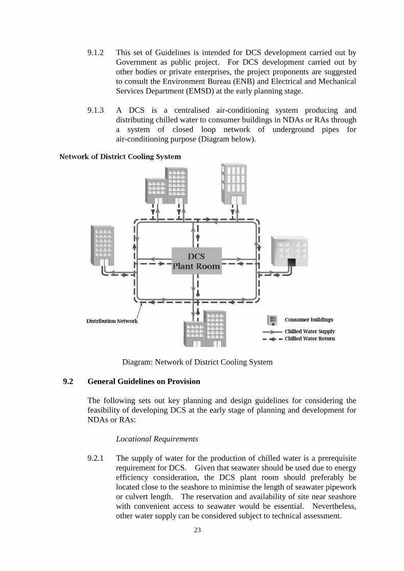
9.1.3 A DCS is a centralised air-conditioning system producing and
distributing chilled water to consumer buildings in NDAs or RAs through
a system of closed loop network of underground pipes for
air-conditioning purpose (Diagram below).
Diagram: Network of District Cooling System
9.2 General Guidelines on Provision
The following sets out key planning and design guidelines for considering the
feasibility of developing DCS at the early stage of planning and development for
NDAs or RAs:
Locational Requirements
9.2.1 The supply of water for the production of chilled water is a prerequisite
requirement for DCS. Given that seawater should be used due to energy
efficiency consideration, the DCS plant room should preferably be
located close to the seashore to minimise the length of seawater pipework
or culvert length. The reservation and availability of site near seashore
with convenient access to seawater would be essential. Nevertheless,
other water supply can be considered subject to technical assessment.
24
9.2.2 A DCS plant room should be close to its targeted consumer buildings in
order to minimise the cost of laying chilled water distribution pipes and
to achieve the maximum effect of energy efficiency. As a general
guideline, the EMSD has recommended that the distance of targeted
consumer buildings away from the DCS plant room should normally not
be more than 2,000m.
Site Requirements and Configurations
9.2.3 For cost-effective operation reason, the minimum site area required for a
standard DCS plant room is 5,400m2 with a typical dimension of 180m x
30m to serve a cooling demand capacity of about 40,000TR (refrigeration
ton). The exact site requirement would depend on the scale of
development that is served by the DCS and should be determined in
consultation with EMSD.
Other Criteria and Considerations
9.2.4 A DCS requires significant cooling demand for being an efficient and
cost-effective alternative to conventional air-conditioning systems. In
general, DCS will only provide chilled water to non-residential
developments since residential developments normally will not adopt
central air-conditioning system which is the prerequisite requirement for
using DCS. In this connection, EMSD recommends that, in general for
planning purposes, there should be a total of 200,000m2 of
non-residential air-conditioning floor area( 5 ) from all targeted consumer
buildings in the NDAs or RAs to warrant a standard DCS to be
financially sustainable.
9.2.5 Since land is a very scarce resource in Hong Kong and there are many
competing land uses to meet various demand in our community, DCS
plant room should preferably be located underground to save the
above-ground of the site for other compatible beneficial land uses. It is
technically feasible for DCS plant room to be located underground such
as beneath a park or playground for most of its components. Sufficient
openings for access should be allowed for operation and maintenance
purposes. However, in case of using cooling towers as the heat
rejection method (due to seawater not available for heat rejection), above
ground structure is required for installation of these cooling towers. The
bulk and height of these above ground structures supporting the DCS
should be minimized as far as practicable so that the design of such
structures could blend into the surroundings.
9.2.6 Standalone / detached DCS plant room should be avoided as far as
possible to optimise land use efficiency, and it should be located in areas
with minimal development potential as far as possible. Co-location of
( 5 ) It may be possible to provide DCS services to residential buildings served by central air-conditioning subject
to request and availability of spare capacity.
25
DCS plant room with other compatible uses should also be considered.
DCS plant room can be made to integrate with plant room of other
infrastructures such as drainage facilities, pumping facilities and flyovers.
Other uses suitable for co-location include uses that are comparatively
less sensitive to noise and vibration and with suitably designed mitigated
measures. For example, these might include public open space, public
car park, Government workshop/storage, public market, etc.
Furthermore, for joint user building development, DCS plant room is
preferably to be accommodated in the basement or on ground floor of a
building as transportation of heavy cooling equipment to higher floors
may impose difficulties to operation and maintenance of the DCS plant
room.
9.3 Considerations at Planning and Implementation Stages
The policy decision of whether a DCS should be developed in NDAs or RAs rests
with ENB while EMSD would provide technical advice and support to ENB.
The feasibility of DCS in NDAs or RAs should be explored in the context of
Planning and Engineering (P&E) studies for NDAs or RAs. For development of
individual DCS outside the context of P&E studies for NDAs or RAs, EMSD
should provide technical advice and support to ENB, conduct detailed feasibility
studies on DCS for confirming the technical feasibility required for the creation of
a new Public Works Programme item. The following technical issues should be
addressed in the study process:
Environmental Impact Considerations
9.3.1 The environmental impacts of a DCS should be assessed in the context of
Environmental Impact Assessment (EIA) for NDA or RA if the NDA or
RA falls within Schedule 3 major designated projects requiring EIA
under the EIA Ordinance (Cap.499).
9.3.2 Water discharges from DCS plant room may have adverse impacts on the
ecology, fisheries and water quality etc. and hence, relevant
environmental assessments such as water quality and air quality impact
assessments will need to be conducted.
9.3.3 As the operation of DCS plant room might generate nuisance to the
sensitive receivers in the vicinity and also to other joint-users, assessment
on the relevant impacts including nuisance affecting the co-users should
be conducted. Appropriate mitigation measures should be proposed to
meet the statutory requirements and planning standards, if applicable, and
minimise the nuisances to any sensitive receivers especially those
building occupants that are sensitive to noise, vibration, humidity etc.
Urban Design Guidelines
9.3.4 For any above ground structures supporting the DCS plant room, in
particular those close to the waterfront/seashore, visual and urban design
concerns should be observed. The design should be responsive to the
26
waterfront setting, and avoid creating visual and physical barrier to the
open water and disruption to the continuous waterfront
promenade. Suitable mitigation measures such as
background-compatible design and landscaping should be incorporated.
The bulk and height of any above ground structures supporting the DCS
should be minimised. Greening opportunities should be explored as far
as possible. Reference can be made to the good design principles for
waterfront sites in the Urban Design Guidelines – Chapter 11 of the
HKPSG.
Technical Guidelines
9.3.5 Reference should be made to the EMSD guidelines on “Technical
Guidelines for Connection to District Cooling System”, which sets out
the general principles and requirements to be applied to the design and
installation works required for connection to DCS, e.g. substation. The
document is available on the website of EMSD (www.emsd.gov.hk).
Early consultation with EMSD at the planning stage is recommended.
9.3.6 Proponents of DCS should follow the relevant statutory and
administrative procedures/requirements as appropriate at the
implementation stage.
27
28
29