Embed Size (px)
Citation preview

1Department of Computer Science and Information Engineering, National Cheng Kung University, Tainan, Taiwan
2 Graduate Institute of Electronics Engineering,
National Taiwan University, Taipei, Taiwan
1Hong-Ting Lin, 2Yi-Lin Chuang, and 1Tsung-Yi Ho
Presenter: Hong-Ting Lin Email: [email protected]
NCKU CSIE EDALAB
International Symposium on Low Power Electronics and Design
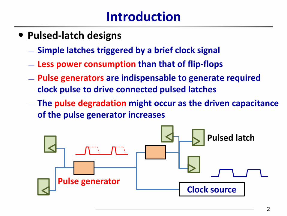
Introduction Pulsed-latch designs
Simple latches triggered by a brief clock signal
Less power consumption than that of flip-flops
Pulse generators are indispensable to generate required clock pulse to drive connected pulsed latches
The pulse degradation might occur as the driven capacitance of the pulse generator increases
2
Pulse generator
Pulsed latch
Clock source
Proposed Migration Flow
To adopt pulsed latches in current design flow, the circuit description should be modified in high-level synthesis which could cause excessive cost and high complexity
3
Flip-flop-based
circuit synthesis
Circuit floorplanning
and placement
Flip-flop-based
clock tree
Flip-flop-based
clock tree synthesis
Traditional design flow
Flip-flop-based
circuit synthesis
Circuit floorplanning
and placement
Pulsed-latch-based
clock tree
Flip-flop-based
clock tree synthesis
Pulsed-latch-based
clock tree migration
Proposed migration flow
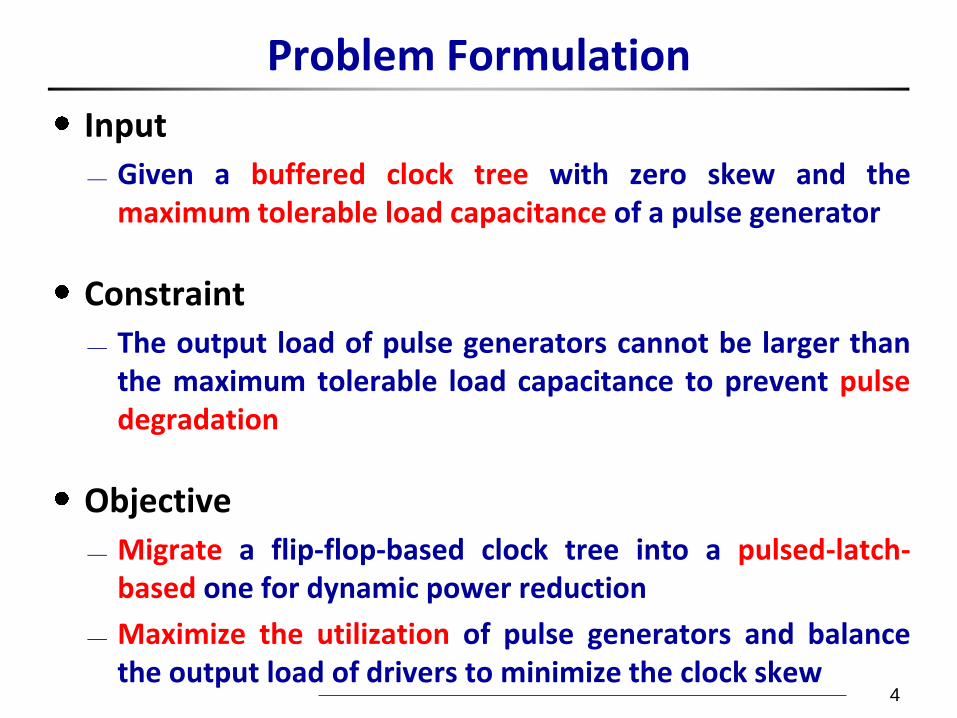
Problem Formulation
Input
Given a buffered clock tree with zero skew and the maximum tolerable load capacitance of a pulse generator
Constraint
The output load of pulse generators cannot be larger than the maximum tolerable load capacitance to prevent pulse degradation
Objective
Migrate a flip-flop-based clock tree into a pulsed-latch-based one for dynamic power reduction
Maximize the utilization of pulse generators and balance the output load of drivers to minimize the clock skew
4
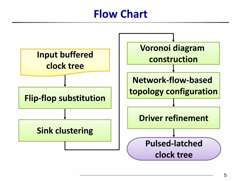
Flow Chart
5
Sink clustering
Input buffered clock tree
Pulsed-latched clock tree
Driver refinement
Network-flow-based topology configuration
Flip-flop substitution
Voronoi diagram construction
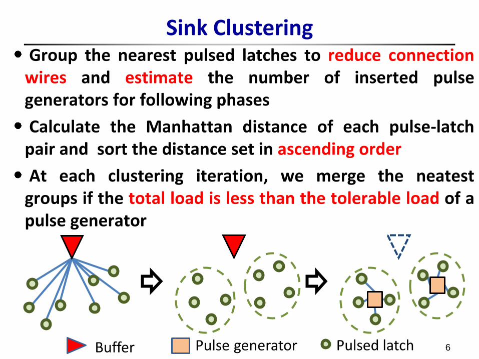
Sink Clustering Group the nearest pulsed latches to reduce connection
wires and estimate the number of inserted pulse generators for following phases
Calculate the Manhattan distance of each pulse-latch pair and sort the distance set in ascending order
At each clustering iteration, we merge the neatest groups if the total load is less than the tolerable load of a pulse generator
6 Buffer Pulse generator Pulsed latch
[4] S. Fortune, “A sweepline algorithm for Voronoi diagrams,” Proc. Annual Symposium on Computational Geometry, 1986
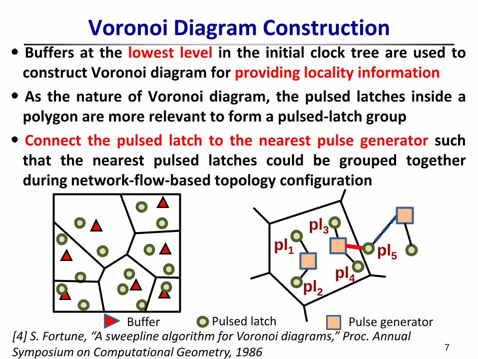
Voronoi Diagram Construction Buffers at the lowest level in the initial clock tree are used to construct Voronoi diagram for providing locality information
As the nature of Voronoi diagram, the pulsed latches inside a polygon are more relevant to form a pulsed-latch group
Connect the pulsed latch to the nearest pulse generator such that the nearest pulsed latches could be grouped together during network-flow-based topology configuration
7
Pulse generator Pulsed latch Buffer
pl1
pl2
pl3
pl4
pl5
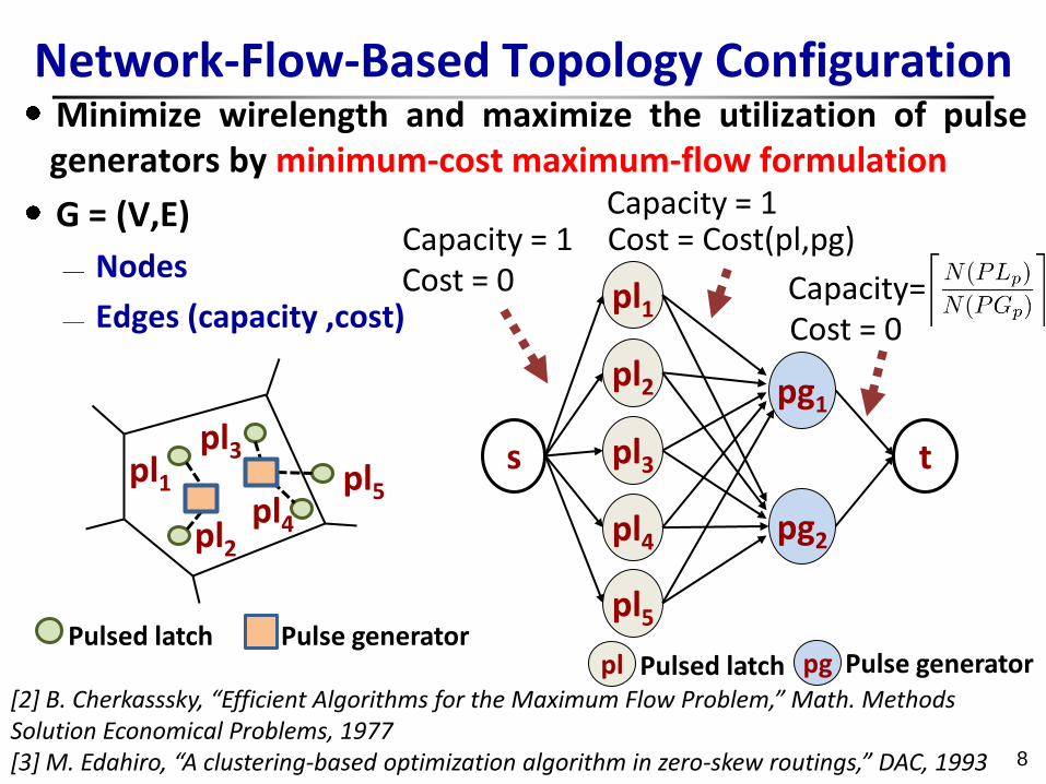
Minimize wirelength and maximize the utilization of pulse generators by minimum-cost maximum-flow formulation
G = (V,E)
Nodes
Edges (capacity ,cost)
[2] B. Cherkasssky, “Efficient Algorithms for the Maximum Flow Problem,” Math. Methods Solution Economical Problems, 1977 [3] M. Edahiro, “A clustering-based optimization algorithm in zero-skew routings,” DAC, 1993
Network-Flow-Based Topology Configuration
8
Cost = 0 Cost = Cost(pl,pg)
Cost = 0
Capacity = 1
Capacity = 1
Capacity=
pl1
pl2
pl3
pl4 pl5
pl2 pg1
pl5
s
pg2
t
pl1
pl3
pl4
Pulse generator Pulsed latch Pulsed latch Pulse generator pl pg
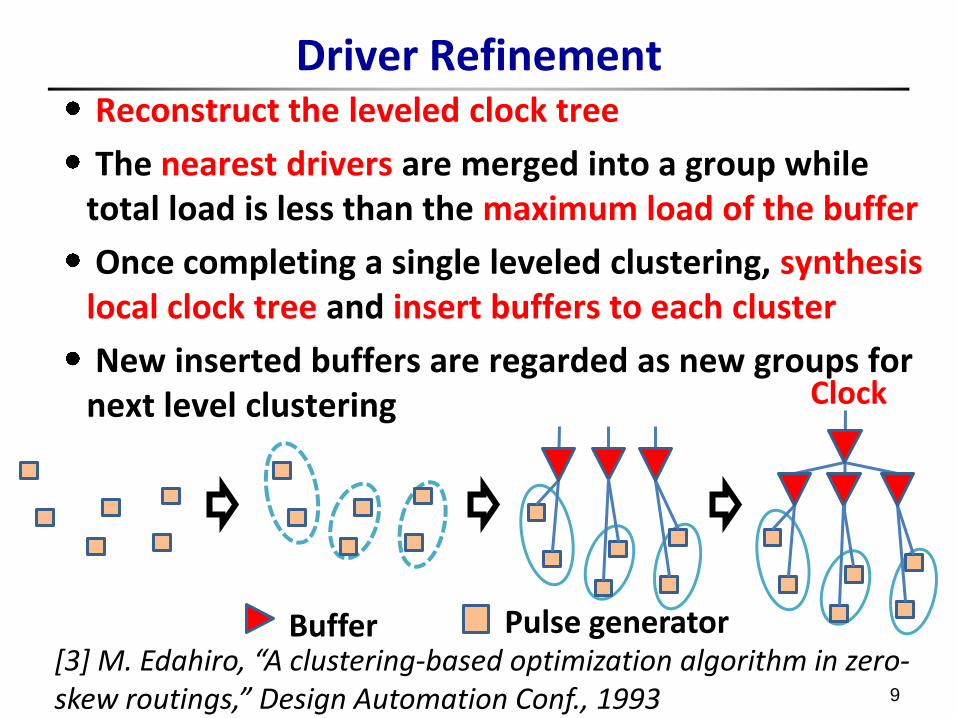
Driver Refinement Reconstruct the leveled clock tree
The nearest drivers are merged into a group while total load is less than the maximum load of the buffer
Once completing a single leveled clustering, synthesis local clock tree and insert buffers to each cluster
New inserted buffers are regarded as new groups for next level clustering
[3] M. Edahiro, “A clustering-based optimization algorithm in zero-skew routings,” Design Automation Conf., 1993 9
Buffer Pulse generator
Clock
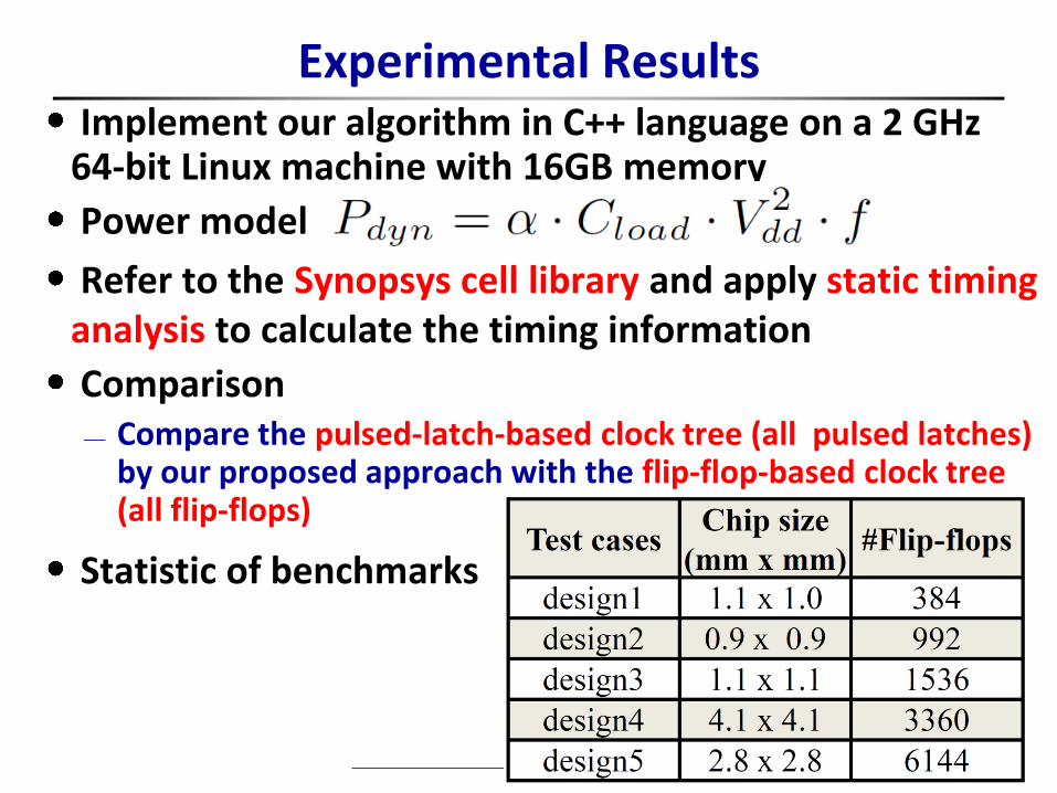
Experimental Results Implement our algorithm in C++ language on a 2 GHz
64-bit Linux machine with 16GB memory
Power model
Refer to the Synopsys cell library and apply static timing analysis to calculate the timing information
Comparison Compare the pulsed-latch-based clock tree (all pulsed latches)
by our proposed approach with the flip-flop-based clock tree (all flip-flops)
Statistic of benchmarks
10
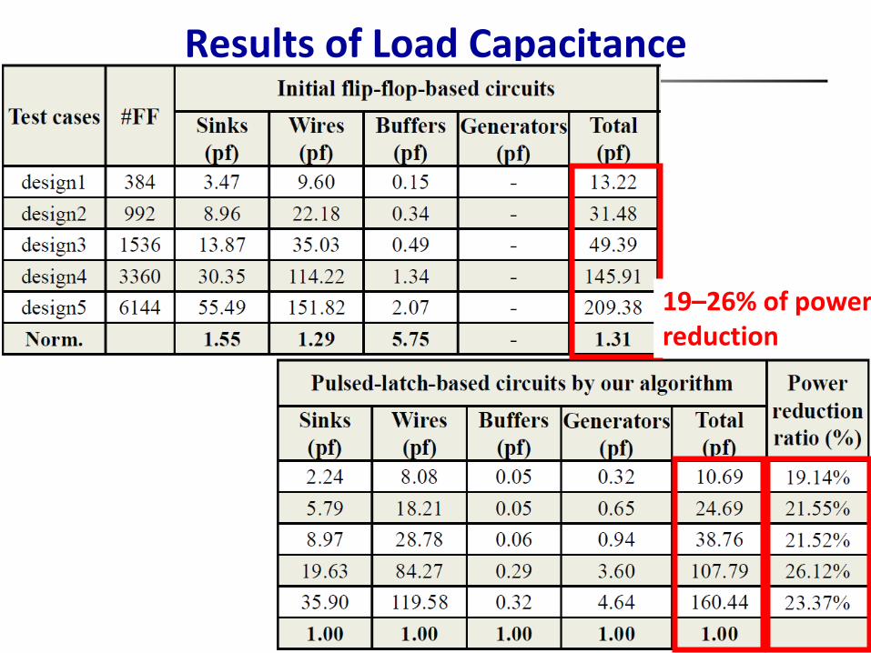
Results of Load Capacitance
11
19–26% of power reduction
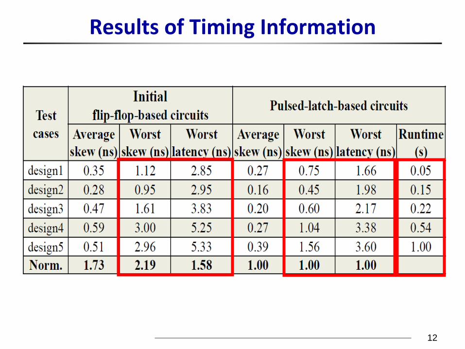
Results of Timing Information
12
Conclusions
A migration approach is proposed which uses pulsed latches to replace flip-flops for dynamic power reduction
Construct a Voronoi diagram to decrease the runtime and minimize wirelength while maximizing the utilization of pulse generators by minimum-cost maximum-flow formulation
Experimental results show that our approach can efficiently migrate the pulsed-latch-based clock tree with smaller power consumption
13

14