Embed Size (px)
Citation preview

ENGLISH
Hook2 X SeriesOperator Manual4x GPS, 4x Sonar, 5x GPS HDI, 7x GPS HDI
www.lowrance.com

Preface
DisclaimerAs Navico is continuously improving this product, we retain theright to make changes to the product at any time which may not bereflected in this version of the manual. Please contact your nearestdistributor if you require any further assistance.
It is the owner’s sole responsibility to install and use the equipmentin a manner that will not cause accidents, personal injury orproperty damage. The user of this product is solely responsible forobserving safe boating practices.
NAVICO HOLDING AS AND ITS SUBSIDIARIES, BRANCHES ANDAFFILIATES DISCLAIM ALL LIABILITY FOR ANY USE OF THIS PRODUCTIN A WAY THAT MAY CAUSE ACCIDENTS, DAMAGE OR THAT MAYVIOLATE THE LAW.
Governing Language: This statement, any instruction manuals, userguides and other information relating to the product(Documentation) may be translated to, or has been translated from,another language (Translation). In the event of any conflict betweenany Translation of the Documentation, the English language versionof the Documentation will be the official version of theDocumentation.
This manual represents the product as at the time of printing.Navico Holding AS and its subsidiaries, branches and affiliatesreserve the right to make changes to specifications without notice.
TrademarksLowrance® and Navico® are registered trademarks of Navico HoldingAS.
Navico product referencesThis manual refers to the following Navico product:
• DownScan Imaging™ (DownScan)
CopyrightCopyright © 2017 Navico Holding AS.
Preface | Hook² X Series Operator Manual 3
WarrantyThe warranty card is supplied as a separate document.
In case of any queries, refer to the brand website of your display orsystem: www.lowrance.com.
Compliance statementsThis equipment complies with:
• CE under 2014/53/EU Directive• The requirements of level 2 devices of the Radio communications
(Electromagnetic Compatibility) standard 2008
The relevant Declaration of Conformity is available in the product'ssection at the following website: www.lowrance.com.
About this manualThis manual is a reference guide for operating the following Hook2 Xmodels: 4x GPS, 4x Sonar, 5x GPS HDI, and 7x GPS HDI.
These units are only capable of the sonar views and frequenciesindicated in the specification included in the transducer’sinstallation guide for the transducer provided with the unit. Themodel is provided on the front of the unit. The following is a list ofthe models, the transducer which should be used and the sonarfunctionality available.
• 4 X Sonar and 4 X GPS: The Bullet transducer should be usedwhich provides traditional sonar functionality only.
• 5 X GPS HDI and 5 X GPS HDI: The SplitShot transducer should beused which provides traditional sonar and DownScanfunctionality.
Transducers added via one of the optional transducer adaptercables will still only have the available views and frequencies thatthe display is designed to work with. Airmar transducers are notsupported via the adapter cable.
In the manual, important text that requires special attention fromthe reader is emphasized as follows:
Ú Note: Used to draw the reader’s attention to a comment orsome important information.
4 Preface | Hook² X Series Operator Manual
Warning: Used when it is necessary to warnpersonnel that they should proceed carefully toprevent risk of injury and/or damage to equipment/personnel.
Preface | Hook² X Series Operator Manual 5

6 Preface | Hook² X Series Operator Manual
Contents
9 Introduction9 Front controls10 Application pages
11 Basic operation11 System Controls dialog11 Settings12 Turning the system on and off12 Display illumination12 Data Overlay13 Stop sonar
14 GPS plotter14 GPS plotter page15 Vessel symbol15 GPS plotter page scale15 Panning the GPS plotter image15 Positioning the vessel on the page16 Waypoints, Routes, and Trails16 Navigating16 GPS plotter settings
18 Waypoints, Routes, and Trails18 Waypoints, Routes, and Trails dialogs19 Waypoints20 Routes20 Trails20 Editing waypoints, routes and trails
22 Navigating22 Navigate to cursor position22 Navigate to a waypoint22 Navigate a route
23 Sonar23 The Sonar image24 Zooming the image
Contents | Hook² X Series Operator Manual 7
24 Customize the image settings24 Custom and Ice Fishing mode options24 Fish ID24 Sonar settings
26 Flasher26 The Flasher image27 Customize the image settings27 Custom and ice fishing mode options
28 DownScan28 The DownScan image28 Zooming the DownScan image28 Customize the image settings
30 Alarms30 Alarm system30 Alarms dialog
31 Maintenance31 Preventive maintenance31 Cleaning the display unit31 Checking the connectors
8 Contents | Hook² X Series Operator Manual
Introduction
Front controls
2
3
546 7
1
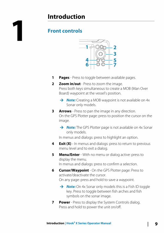
1 Pages - Press to toggle between available pages.
2 Zoom in/out - Press to zoom the image.Press both keys simultaneous to create a MOB (Man OverBoard) waypoint at the vessel's position.
Ú Note: Creating a MOB waypoint is not available on 4xSonar only models.
3 Arrows - Press to pan the image in any direction.On the GPS Plotter page: press to position the cursor on theimage.
Ú Note: The GPS Plotter page is not available on 4x Sonaronly models.
In menus and dialogs: press to highlight an option.
4 Exit (X) - In menus and dialogs: press to return to previousmenu level and to exit a dialog.
5 Menu/Enter - With no menu or dialog active: press todisplay the menu.In menus and dialogs: press to confirm a selection.
6 Cursor/Waypoint - On the GPS Plotter page: Press toactivate/deactivate the cursor.On any page: press and hold to save a waypoint.
Ú Note: On 4x Sonar only models this is a Fish ID togglekey. Press to toggle between fish arches and fishsymbols on the sonar image.
7 Power - Press to display the System Controls dialog.Press and hold to power the unit on/off.
1
Introduction | Hook² X Series Operator Manual 9
Application pages
1
3
2 4
5
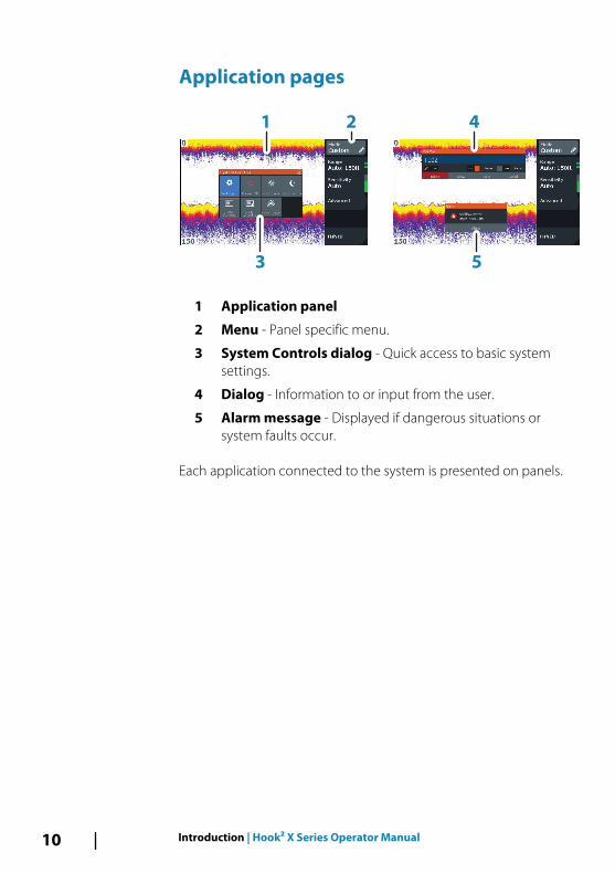
1 Application panel
2 Menu - Panel specific menu.
3 System Controls dialog - Quick access to basic systemsettings.
4 Dialog - Information to or input from the user.
5 Alarm message - Displayed if dangerous situations orsystem faults occur.
Each application connected to the system is presented on panels.
10 Introduction | Hook² X Series Operator Manual
Basic operation
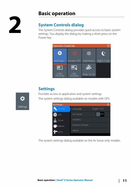
System Controls dialogThe System Controls dialog provides quick access to basic systemsettings. You display the dialog by making a short press on thePower key.
SettingsProvides access to application and system settings.
The system settings dialog available on models with GPS.
The system settings dialog available on the 4x Sonar only models.
2
Basic operation | Hook² X Series Operator Manual 11
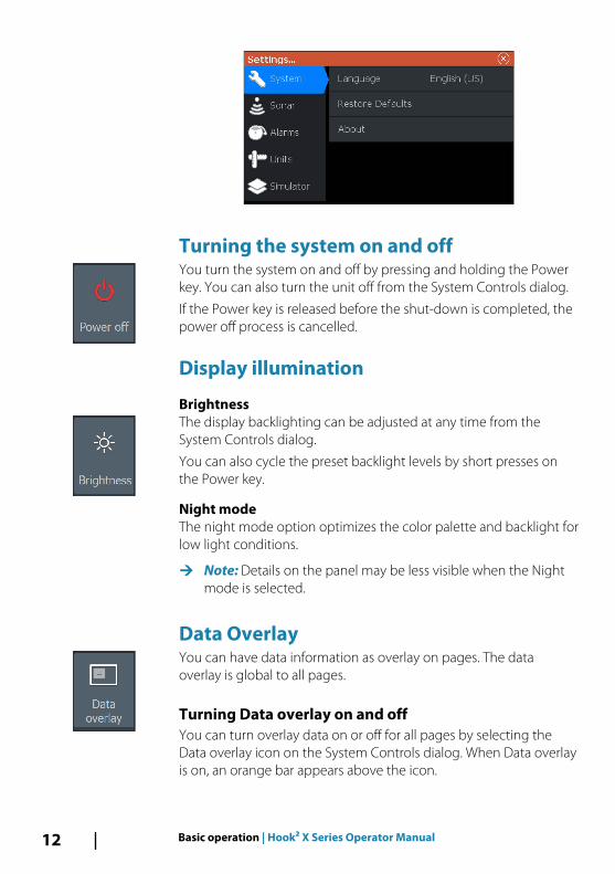
Turning the system on and offYou turn the system on and off by pressing and holding the Powerkey. You can also turn the unit off from the System Controls dialog.
If the Power key is released before the shut-down is completed, thepower off process is cancelled.
Display illumination
BrightnessThe display backlighting can be adjusted at any time from theSystem Controls dialog.
You can also cycle the preset backlight levels by short presses onthe Power key.
Night modeThe night mode option optimizes the color palette and backlight forlow light conditions.
Ú Note: Details on the panel may be less visible when the Nightmode is selected.
Data OverlayYou can have data information as overlay on pages. The dataoverlay is global to all pages.
Turning Data overlay on and offYou can turn overlay data on or off for all pages by selecting theData overlay icon on the System Controls dialog. When Data overlayis on, an orange bar appears above the icon.
12 Basic operation | Hook² X Series Operator Manual
Edit overlay dataOn models with GPS, you can have up to 3 data overlays on theGPS , sonar and DownScan (available on 5x and 7x models only)pages. Use the Edit overlay option on the System Controls dialog to:
• Change a selected data overlay to display different data.• Select a predefined size from the size drop-down list.• Select the OFF option in the predefined size drop-down list to
remove the selected data overlay from the page.
On 4x Sonar only models, you can have up to 3 data overlays on thesonar page. Use the Edit overlay option on the System Controlsdialog to:
• Select a predefined size from the size drop-down list.• Select the OFF option in the predefined size drop-down list to
remove the selected data overlay from the page.
Stop sonarSelect the Stop sonar option in the System Controls dialog to stopall sonar from pinging. Use the stop sonar option anytime you wantto disable all sonar but not power off the unit.
Basic operation | Hook² X Series Operator Manual 13
GPS plotter
Ú Note: The GPS plotter page is not available on 4x Sonar onlymodels.
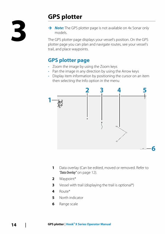
The GPS plotter page displays your vessel’s position. On the GPSplotter page you can plan and navigate routes, see your vessel'strail, and place waypoints.
GPS plotter page• Zoom the image by using the Zoom keys• Pan the image in any direction by using the Arrow keys• Display item information by positioning the cursor on an item
then selecting the Info option in the menu
1
2 3
6
4 5
1 Data overlay (Can be edited, moved or removed. Refer to"Data Overlay" on page 12).
2 Waypoint*
3 Vessel with trail (displaying the trail is optional*)
4 Route*
5 North indicator
6 Range scale
3
14 GPS plotter | Hook² X Series Operator Manual
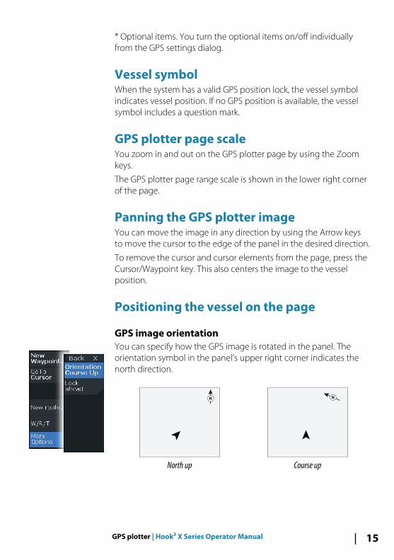
* Optional items. You turn the optional items on/off individuallyfrom the GPS settings dialog.
Vessel symbolWhen the system has a valid GPS position lock, the vessel symbolindicates vessel position. If no GPS position is available, the vesselsymbol includes a question mark.
GPS plotter page scaleYou zoom in and out on the GPS plotter page by using the Zoomkeys.
The GPS plotter page range scale is shown in the lower right cornerof the page.
Panning the GPS plotter imageYou can move the image in any direction by using the Arrow keysto move the cursor to the edge of the panel in the desired direction.
To remove the cursor and cursor elements from the page, press theCursor/Waypoint key. This also centers the image to the vesselposition.
Positioning the vessel on the page
GPS image orientationYou can specify how the GPS image is rotated in the panel. Theorientation symbol in the panel’s upper right corner indicates thenorth direction.
N
North up
N
Course up
GPS plotter | Hook² X Series Operator Manual 15
North upDisplays the GPS plotter image with north upward.
Course upThe GPS plotter image direction is depending on if navigating ornot:
• when navigating: the desired course is oriented up• if not navigating: the direction the vessel is actually traveling
(COG) is oriented up
Look aheadMoves the vessel icon on the panel to maximize your view ahead ofthe vessel.
Waypoints, Routes, and TrailsYou can position and manage waypoints, routes and trails on thepage. For more information, refer to "Waypoints, Routes, and Trails" onpage 18.
Navigating You can use the page for navigating to the cursor, to a waypoint, ornavigate a route. Refer to "Navigating" on page 22.
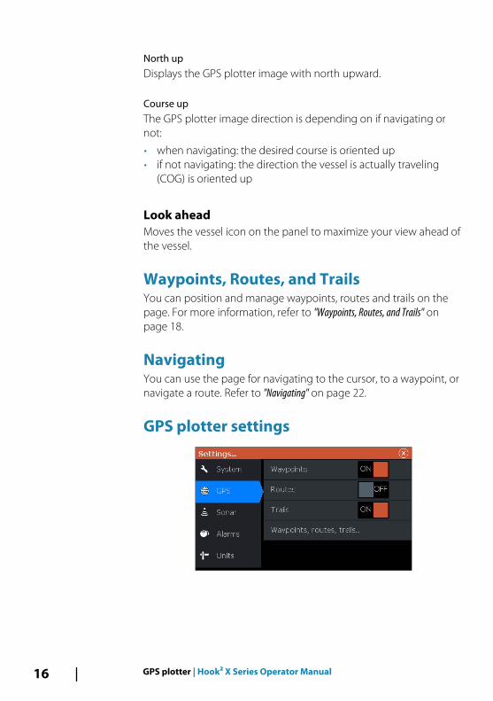
GPS plotter settings
16 GPS plotter | Hook² X Series Operator Manual
Waypoints, Routes, and Trails• Waypoints - specifies whether waypoints are (ON) or are not
(OFF) displayed on the GPS image.• Routes - specifies whether routes are (ON) or are not (OFF)
displayed on the GPS image.• Trails - specifies whether trails are (ON) or are not (OFF) displayed
on the GPS image.• Waypoints, routes, trails... - opens the waypoints, routes, and trails
dialogs. Use these dialogs to manage waypoints, routes, andtrails. Refer to "Waypoints, Routes, and dialogs" on page 18.
GPS plotter | Hook² X Series Operator Manual 17
Waypoints, Routes, and Trails
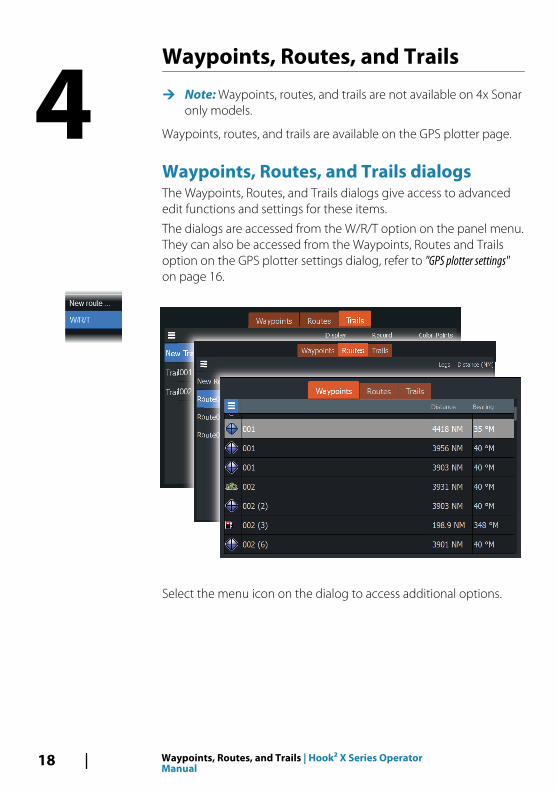
Ú Note: Waypoints, routes, and trails are not available on 4x Sonaronly models.
Waypoints, routes, and trails are available on the GPS plotter page.
Waypoints, Routes, and Trails dialogsThe Waypoints, Routes, and Trails dialogs give access to advancededit functions and settings for these items.
The dialogs are accessed from the W/R/T option on the panel menu.They can also be accessed from the Waypoints, Routes and Trailsoption on the GPS plotter settings dialog, refer to "GPS plotter settings"on page 16.
Select the menu icon on the dialog to access additional options.
4
18 Waypoints, Routes, and Trails | Hook² X Series OperatorManual
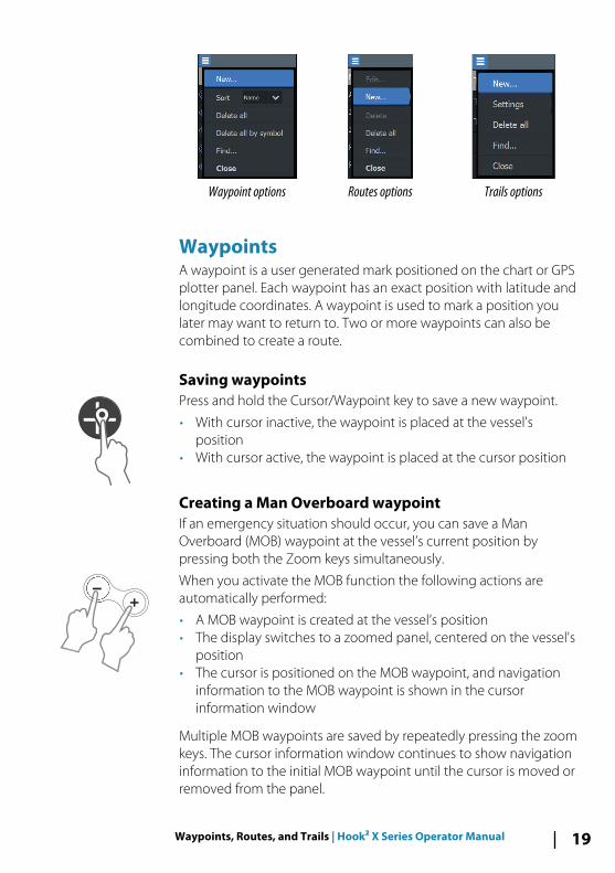
Waypoint options Routes options Trails options
WaypointsA waypoint is a user generated mark positioned on the chart or GPSplotter panel. Each waypoint has an exact position with latitude andlongitude coordinates. A waypoint is used to mark a position youlater may want to return to. Two or more waypoints can also becombined to create a route.
Saving waypointsPress and hold the Cursor/Waypoint key to save a new waypoint.
• With cursor inactive, the waypoint is placed at the vessel'sposition
• With cursor active, the waypoint is placed at the cursor position
Creating a Man Overboard waypointIf an emergency situation should occur, you can save a ManOverboard (MOB) waypoint at the vessel’s current position bypressing both the Zoom keys simultaneously.
When you activate the MOB function the following actions areautomatically performed:
• A MOB waypoint is created at the vessel’s position• The display switches to a zoomed panel, centered on the vessel's
position• The cursor is positioned on the MOB waypoint, and navigation
information to the MOB waypoint is shown in the cursorinformation window
Multiple MOB waypoints are saved by repeatedly pressing the zoomkeys. The cursor information window continues to show navigationinformation to the initial MOB waypoint until the cursor is moved orremoved from the panel.
Waypoints, Routes, and Trails | Hook² X Series Operator Manual 19
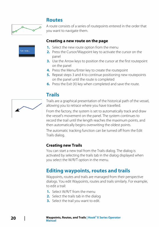
RoutesA route consists of a series of routepoints entered in the order thatyou want to navigate them.
Creating a new route on the page1. Select the new route option from the menu2. Press the Cursor/Waypoint key to activate the cursor on the
panel3. Use the Arrow keys to position the cursor at the first routepoint
on the panel4. Press the Menu/Enter key to create the routepoint5. Repeat steps 3 and 4 to continue positioning new routepoints
on the panel until the route is completed6. Press the Exit (X) key when completed and save the route.
TrailsTrails are a graphical presentation of the historical path of the vessel,allowing you to retrace where you have travelled.
From the factory, the system is set to automatically track and drawthe vessel's movement on the panel. The system continues torecord the trail until the length reaches the maximum points, andthen automatically begins overwriting the oldest points.
The automatic tracking function can be turned off from the EditTrails dialog.
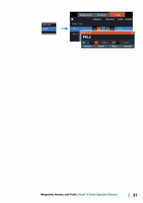
Creating new TrailsYou can start a new trail from the Trails dialog. The dialog isactivated by selecting the trails tab in the dialog displayed whenyou select the W/R/T option in the menu.
Editing waypoints, routes and trails Waypoints, routes and trails are managed from their perspectivedialogs. You edit Waypoints, routes and trails similarly. For example,to edit a trail:
1. Select W/R/T from the menu2. Select the trails tab in the dialog3. Select the trail you want to edit.
20 Waypoints, Routes, and Trails | Hook² X Series OperatorManual
Waypoints, Routes, and Trails | Hook² X Series Operator Manual 21
Navigating
Ú Note: Navigating is not available on 4x Sonar only models.
The navigation function is available on the GPS page.
The navigation function included in the system allows you tonavigate to the cursor position, to a waypoint, or along a predefinedroute.
For information about positioning waypoints and creating routes,refer to "Waypoints, Routes, and Trails" on page 18.
When you select to navigate to the cursor position, to a waypoint ora predefined route, the Navigation option appears in the menu.Select Navigate to access cancel, restart, and skip a routepointoptions.
Navigate to cursor positionYou can start navigating to a cursor position on the GPS plotter orsonar panel.
Position the cursor at the selected destination on the panel, andthen select the Goto Cursor option in the menu.
Ú Note: The Goto Cursor menu option is not available if you arealready navigating.
Navigate to a waypointYou can start navigating towards a waypoint on the panel. Positionthe cursor over the waypoint, select the waypoint in the menu andthen the Goto waypoint option in the menu.
Navigate a routeYou can navigate a route on the image by positioning the cursorover the route, selecting the route in the menu and then the startroute option in the menu.
When route navigation is started, select the Navigation menuoption for canceling the navigation, skipping a waypoint, andrestarting the route from current vessel position.
5
22 Navigating | Hook² X Series Operator Manual
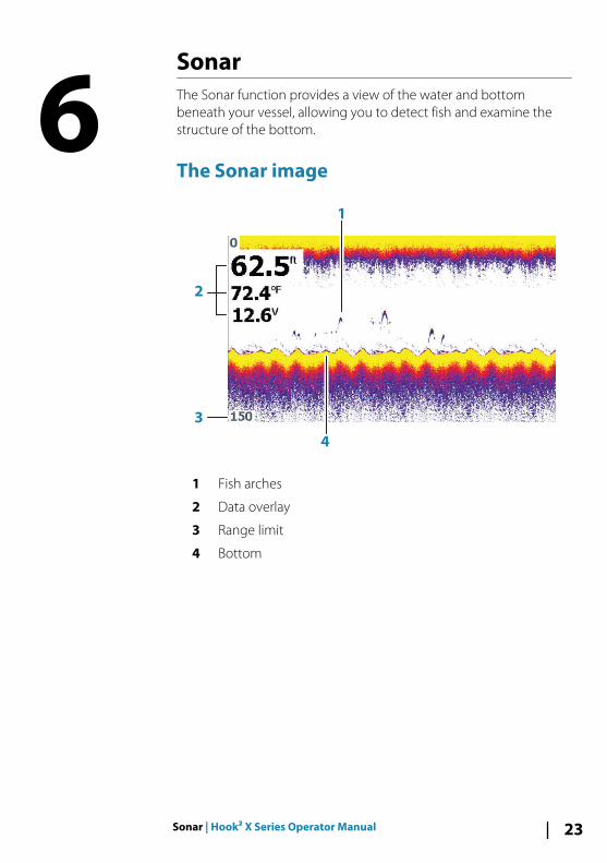
SonarThe Sonar function provides a view of the water and bottombeneath your vessel, allowing you to detect fish and examine thestructure of the bottom.
The Sonar image
3
2
4
1
1 Fish arches
2 Data overlay
3 Range limit
4 Bottom
6
Sonar | Hook² X Series Operator Manual 23
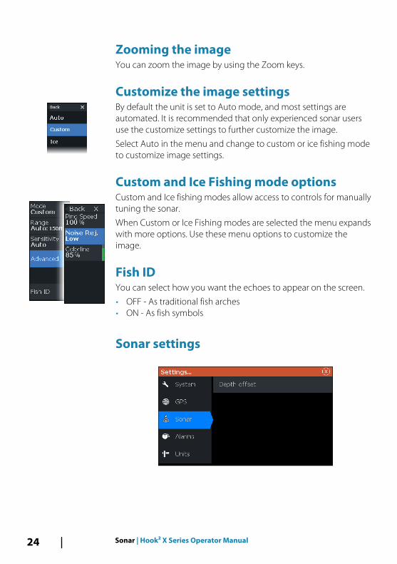
Zooming the imageYou can zoom the image by using the Zoom keys.
Customize the image settingsBy default the unit is set to Auto mode, and most settings areautomated. It is recommended that only experienced sonar usersuse the customize settings to further customize the image.
Select Auto in the menu and change to custom or ice fishing modeto customize image settings.
Custom and Ice Fishing mode optionsCustom and Ice fishing modes allow access to controls for manuallytuning the sonar.
When Custom or Ice Fishing modes are selected the menu expandswith more options. Use these menu options to customize theimage.
Fish IDYou can select how you want the echoes to appear on the screen.
• OFF - As traditional fish arches• ON - As fish symbols
Sonar settings
24 Sonar | Hook² X Series Operator Manual
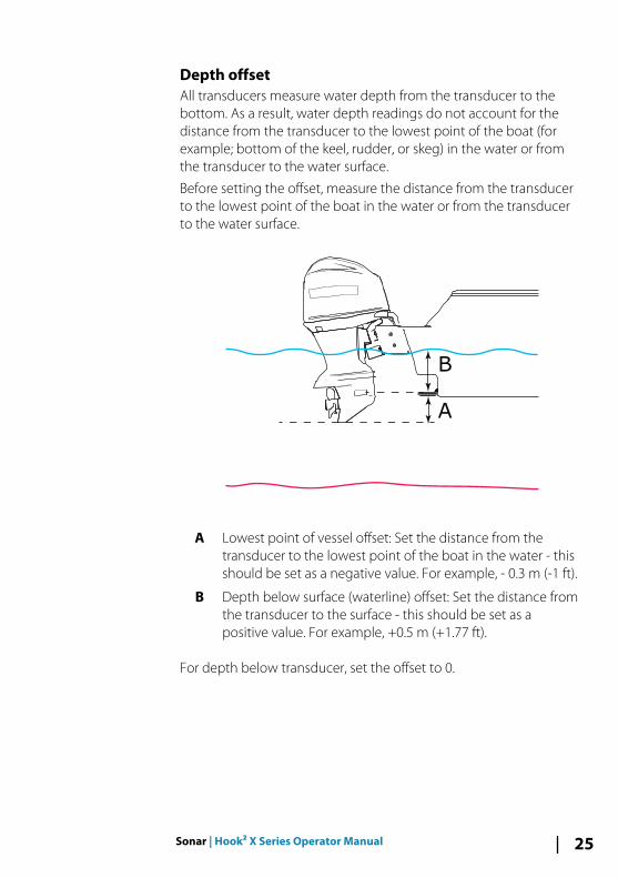
Depth offsetAll transducers measure water depth from the transducer to thebottom. As a result, water depth readings do not account for thedistance from the transducer to the lowest point of the boat (forexample; bottom of the keel, rudder, or skeg) in the water or fromthe transducer to the water surface.
Before setting the offset, measure the distance from the transducerto the lowest point of the boat in the water or from the transducerto the water surface.
A
B
A Lowest point of vessel offset: Set the distance from thetransducer to the lowest point of the boat in the water - thisshould be set as a negative value. For example, - 0.3 m (-1 ft).
B Depth below surface (waterline) offset: Set the distance fromthe transducer to the surface - this should be set as apositive value. For example, +0.5 m (+1.77 ft).
For depth below transducer, set the offset to 0.
Sonar | Hook² X Series Operator Manual 25
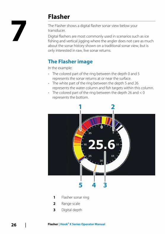
FlasherThe Flasher shows a digital flasher sonar view below yourtransducer.
Digital flashers are most commonly used in scenarios such as icefishing and vertical jigging where the angler does not care as muchabout the sonar history shown on a traditional sonar view, but isonly interested in raw, live sonar returns.
The Flasher imageIn the example:
• The colored part of the ring between the depth 0 and 5represents the sonar returns at or near the surface.
• The white part of the ring between the depth 5 and 26represents the water column and fish targets within this column.
• The colored part of the ring between the depth 26 and < 0represents the bottom.
34
1 2
5
1 Flasher sonar ring
2 Range scale
3 Digital depth
7
26 Flasher | Hook² X Series Operator Manual
4 Water column activity (fish, bait fish, etc.)
5 Depth
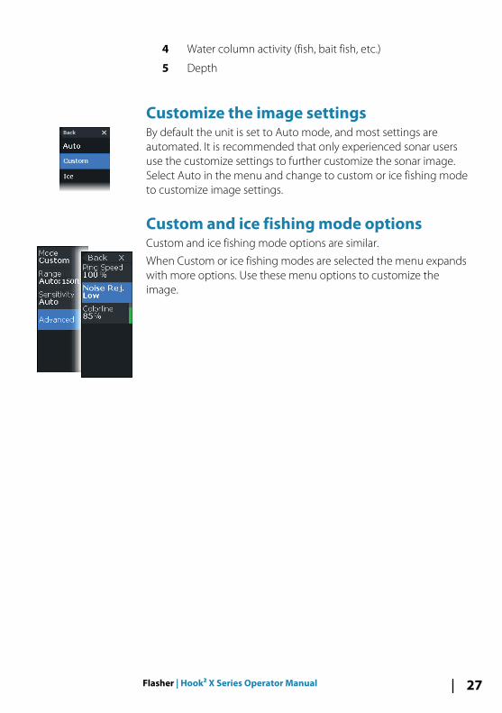
Customize the image settingsBy default the unit is set to Auto mode, and most settings areautomated. It is recommended that only experienced sonar usersuse the customize settings to further customize the sonar image.Select Auto in the menu and change to custom or ice fishing modeto customize image settings.
Custom and ice fishing mode optionsCustom and ice fishing mode options are similar.
When Custom or ice fishing modes are selected the menu expandswith more options. Use these menu options to customize theimage.
Flasher | Hook² X Series Operator Manual 27
DownScan
Ú Note: DownScan is available on 5x and 7x models only.
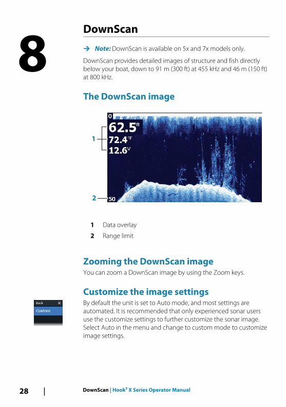
DownScan provides detailed images of structure and fish directlybelow your boat, down to 91 m (300 ft) at 455 kHz and 46 m (150 ft)at 800 kHz.
The DownScan image
2
1
1 Data overlay
2 Range limit
Zooming the DownScan imageYou can zoom a DownScan image by using the Zoom keys.
Customize the image settingsBy default the unit is set to Auto mode, and most settings areautomated. It is recommended that only experienced sonar usersuse the customize settings to further customize the sonar image.Select Auto in the menu and change to custom mode to customizeimage settings.
8
28 DownScan | Hook² X Series Operator Manual
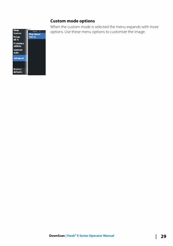
Custom mode optionsWhen the custom mode is selected the menu expands with moreoptions. Use these menu options to customize the image.
DownScan | Hook² X Series Operator Manual 29
Alarms
Alarm systemThe system continuously checks for dangerous situations andsystem faults while the system is running. When an alarm situationoccurs, an alarm message pops up on the screen.
If you have enabled the siren, the alarm message is followed by anaudible alarm.
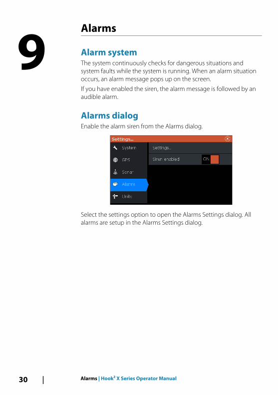
Alarms dialogEnable the alarm siren from the Alarms dialog.
Select the settings option to open the Alarms Settings dialog. Allalarms are setup in the Alarms Settings dialog.
9
30 Alarms | Hook² X Series Operator Manual
Maintenance
Preventive maintenanceThe unit does not contain any field serviceable components.Therefore, the operator is required to perform only a very limitedamount of preventative maintenance.
It is recommended that you always fit the protective sun coverwhen the unit is not in use.
Ú Note: The protective sun cover is an accessory (sold separately).Refer to the Installation guide provided with your unit.
Cleaning the display unitTo clean the screen:
• A micro-fiber or a soft cotton cloth should be used to clean thescreen. Use plenty of water to dissolve and take away saltremains. Crystallized salt, sand, dirt, etc. can scratch the protectivecoating if using a damp cloth. Use a light fresh water spray thenwipe the unit dry with a micro-fiber or a soft cotton cloth. Do notapply pressure with the cloth.
To clean the housing:
• Use warm water with a dash of liquid dish soap or detergent.
Avoid using abrasive cleaning products or products containingsolvents (acetone, mineral turpentine, etc.), acid, ammonia, oralcohol as they can damage the display and plastic housing.
Do not use a jet or high pressure wash. Do not run your unitthrough a car wash.
Checking the connectorsThe connectors should be checked by visual inspection only.
Push the connector plugs into the connector. If the connector plugsare equipped with a position key, ensure that it is in the correctposition.
10
Maintenance | Hook² X Series Operator Manual 31

32 Maintenance | Hook² X Series Operator Manual


*988
-117
47-0
01*