Embed Size (px)
Citation preview

Enclosure 3 Contains Proprietary I nformation to be Withheld from Publ ic Disclosure Pursuant to 1 0 CFR 2.390
PSEG Nuclear LLC P.O. Box 236, Hancocks Bridge, NJ 08038-0236
SEP 21 2015
LR-N1 5-01 78 LAR H 1 5-01
U .S. Nuclear Regu latory Commission ATTN: Document Control Desk Wash ington, DC 20555-0001
Hope Creek Generating Station Renewed Facil ity Operating License No. NPF-57 NRC Docket No. 50-354
PSI�G NucleaT LLC
1 0 CFR 50.90
Subject: LICENSE AME NDMENT REQUEST- DIGITAL POWER RANGE NEUTRON MONITORI NG (PRNM) SYSTEM UPGRADE
I n accordance with 1 0 CFR 50.90, PSEG Nuclear LLC (PSEG) hereby requests an amend ment to Renewed Facil ity Operating L icense No. NPF-57 for Hope Creek Generating Station (HCGS). I n accordance with 1 0 CFR 50.9 1 (b)( 1 ) , a copy of this request for amendment has been sent to the State of New Jersey.
The proposed l icense amendment request (LAR) would reflect the installation of the General Electric-H itachi (GEH) d ig ital Nuclear Measurement Analysis and Control (NU MAC) Power Range Neutron Monitoring (PRNM) system . The fo l lowing Technical Specifications (TS) sections are affected by this change:
• TS 2 .2 Limiting Safety System Settings • TS 3/4. 1 .4 .3 Rod Block Mon itor • TS 3/4.3.1 Reactor Protection System Instrumentation • TS 3/4.3 .6 Control Rod Block Instrumentation • TS 3/4 .3. 1 1 Osci l lation Power Range Monitor • TS 3/4.4. 1 Recircu lation System • TS 6 .9 . 1 .9 Core Operating Limits Report • TS 6 .9 .3 Specia l Reports
The planned u pgrade wi l l replace the exist ing analog Average Power Range Monitor (APRM) sub-system of the Neutron Monitoring System with the more rel iable, d ig ital NUMAC PRNM

SEP' 21 2015 Page 2 LR-N 1 5-01 78
E nclosure 3 Contains Proprietary I nformation to be Withheld from Publ ic Disclosure Pursuant to 1 0 CFR 2.390
1 0 CFR 50.90
System . The PRNM u pgrade wi l l include Osci l lation Power Range Monitor (OPRM) capabi l ity, wi l l a l low fu l l Average power range monitor, Rod block monitor, Technica l Specification improvement program (ARTS) implementation , and wi l l include appl ication of TSTF-493 to affected PRNM functions.
A s imi lar PRNM system was approved for installation at Columbia Generating Station (CGS), and serves as a precedent for the HCGS instal lation .
The NRC has issued I nterim Staff Guidance ( ISG) i n dig ita l i nstrumentation and control (D I&C) D I&C- ISG-06 that describes the l icensing process that may be used in the review of LARs associated with dig ital I&C system modifications. The format and contents of this LAR (primarily Section 4 of Attachment 1 ) are consistent with the gu idance provided in Enclosure E and Section C .3 of DI&C-ISG-06 . Prior to the subm ittal of this LAR, PSEG held three pre-appl ication (D I&C-ISG,.06 Phase 0) meeti ngs with the NRC Staff on September 1 1 , 201 3 (ADAMS ML 1 3364A242) , August 1 2 , 201 4 (ADAMS ML 1 4224A1 33) and January 29, 201 5 (ADAMS ML 1 5043A239) .
D I&C-ISG-06 describes three different tiers of appl ications for approval of I&C system modifications. This appl ication is a Tier 2 appl ication referencing a previously approved topical report with deviations to su it the plant-specific appl ication .
D I&C- ISG-06, Enclosure B, l ists documents that are typ ical ly submitted by the l icensee in support of a Tier 2 submittal during Phases 1 and 2 of the NRC staff review. The Phase 1 documents that are associated with this submittal are provided in Enclosure 2 (Non-Proprietary) and Enclosure 3 (Proprietary). A roadmap, or cross-reference, between the ISG-06 Enclosure B document name and the equivalent document supporting this appl ication is provided in Enclosure 1 of th is submittal .
D I&C-ISG-06 Enclosu re B identifies Phase 2 documents to be submitted with i n twelve months of the requested approval date. D I&C-ISG-06 Section C.4 states that documentation may be submitted in less than twelve months prior to the anticipated issuance of the amendment as mutual ly agreed with the staff in the Phase 0 meetings. Some Phase 2 documents requ ire manufacture and factory acceptance testing to complete the document. The Phase 2 documents wi l l be provided approximately one year after this Phase 1 submittal.
Attachment 1 provides the evaluation of the proposed LAR changes. Attachment 2 provides the marked-up TS pages. Attachment 3 provides marked up TS Bases pages.
The fol lowing Enclosu res are i ncluded with this submitta l :
• Enclosure 1 - HCGS PRNM Upgrade - ISG-06 Enclosure B Roadmap • Enclosure 2 - NED0-33864, Hope Creek Generating Station NUMAC PRNM Upgrade
(Non-Proprietary) • Enclosure 3 - NEDC-33864P, Hope Creek Generating Station NUMAC PRNM Upgrade
(Proprietary)

Page 3 LR-N1 5-01 78
Enclosure 3 Contains Proprietary I nformation to be Withheld from Publ ic Disclosure Pursuant to 1 0 CFR 2.390
10 CFR 50.90
Enclosu re 3 contains proprietary information as defined by 1 0 CFR 2 .390. GEI-I, as the owner of the proprietary information, has executed the Enclosure 3 affidavit(s) identifying that the proprietary i nformation has been hand led and classified as proprietary, is customari ly held in confidence, and has been withheld from public disclosure. GEH requests that the proprietary i nformation in Enclosu re 3 be withheld from publ ic d isclosure, in accordance with the requ i rements of 1 0 CFR 2 .390(a)(4).
PSEG requests approval of this LAR by the end of the fourth quarter 201 7, to support instal lation i n the Spring 201 8 Refuel ing Outage (RF2 1 ) . PSEG requests the l icense amendments be made effective upon NRC issuance, to be implemented prior to entry into OPCON 4 during startup from RF2 1 .
No new regulatory commitments are establ ished by th is submitta l . The proposed changes have been reviewed by the Plant Operating Review Committee. If you have any q uestions or require additional information, p lease do not hes itate to contact Mr. Brian Thomas at (856) 339-2022.
I declare under penalty of perj ury that the foregoing is true and correct.
q(::"l l\ ( r Executed on I (.7\ .J --lk----''-----(Date)
Respectfu l ly,
?o.Ju� Paul Davison S ite Vice President Hope Creek Generating Station
Attachments (3)
1 . License Amendment Request (LAR) H 1 5-01 - Dig ital Power Range Neutron Monitoring (PRNM) System Upgrade
2. Mark-up of Proposed Technical Specification Pages 3. Mark-up of Proposed Technical Specification Bases Pages
Enclosures (3)
1 . H CGS PRNM Upgrade - ISG-06 Enclosure B Roadmap 2. NED0-33864: Hope Creek Generating Station NU MAC PRNM Upgrade- Non
Proprietary 3. NEDC-33864P: Hope Creek Generating Station NU MAC PRNM Upgrade - Proprietary
(Withhold from Public Disclosure Pursuant to 10 CFR 2. 390)
Page 4 LR-N 1 5-01 78
Enclosure 3 Contains Proprietary I nformation to be Withheld from Public Disclosure Pursuant to 1 0 CFR 2.390
cc: Mr. D. Dorman, Admin istrator, Region I, NRC Mr. T. Wengert, Project Manager, NRC NRC Senior Resident I nspector, Hope Creek Mr. P. Mulligan , Chief, NJBNE Mr. L . Marabella , Corporate Commitment Tracking Coord inator Mr. T . MacEwen , Hope Creek Commitment Tracking Coord inator
1 0 CFR 50.90

Attachment 1 LAR H15-01 LR-N15-0178
1 of 47
License Amendment Request (LAR) H15-01 –– Digital Power Range Neutron Monitoring (PRNM) System Upgrade
Table of Contents 1.0 DESCRIPTION ................................................................................................................... 2 2.0 PROPOSED CHANGE - Technical Specifications (Section D.11 of DI&C-ISG-06) ........... 4 3.0 BACKGROUND ................................................................................................................ 24 4.0 TECHNICAL ANALYSIS ................................................................................................... 26
4.1 System Description (Section D.1 of DI&C-ISG-06)....................................................... 27 4.1.1 Summary Description ............................................................................................. 27 4.1.2 Detailed System Description .................................................................................. 30
4.1.2.1 PRNM LTR Plant Specific Responses ........................................................... 31 4.1.2.2 OPRM Transition to DSS-CD ......................................................................... 31 4.1.2.3 Transition to Full ARTS .................................................................................. 32 4.1.2.4 Cyber Security Considerations ....................................................................... 33 4.1.2.5 Human Factors Evaluation ............................................................................. 33 4.1.2.6 TSTF-493 ....................................................................................................... 34
4.1.3 System Response Time ......................................................................................... 35 4.2 System (Hardware and Software) Development for the HCGS PRNM System (Section
D.2 and D.4 of DI&C-ISG-06) ....................................................................................... 35 4.2.1 Design Analysis Report: Methodology Modifications ............................................. 35 4.2.2 NUMAC System Engineering Development Plan ................................................... 36 4.2.3 NUMAC System Quality Assurance Plan ............................................................... 36 4.2.4 NUMAC System Independent Verification & Validation Plan ................................. 36 4.2.5 Hope Creek Generating Station NUMAC PRNM System Management Plan ........ 36
4.3 Software Architecture / Design Outputs (Section D.3 of DI&C-ISG-06) ....................... 36 4.3.1 System Requirements Specification & APRM Performance Specification ............. 37 4.3.2 APRM Functional Controller System Design Specification .................................... 37
4.4 Environmental Equipment Qualification (Section D.5 of DI&C-ISG-06) ........................ 37 4.5 Defense-In-Depth & Diversity (Section D.6 of DI&C-ISG-06) ....................................... 38 4.6 Communications (Section D.7 of DI&C-ISG-06) ........................................................... 38 4.7 System, Hardware, Software, and Methodology Modifications (Deviations from the
Prior LTRs) (Section D.8 of DI&CISG-06) .................................................................... 38 4.8 Compliance with IEEE Standard 603 (Section D.9 of DI&C-ISG-06) ........................... 38
4.8.1 Report on Compliance with IEEE Standards (603-1991 and 7-4.3.2-2003) and Theory of Operations Description ........................................................................... 39
4.8.2 Design Report on Computer Integrity, Test and Calibration, and Fault Detection (IEEE Standard 603-1991 Clause 5.5) ................................................................... 39
4.8.3 Design Analysis Report: Electrical Independence (IEEE Standard 603-1991 Clause 5.6) ......................................................................................................................... 39
4.8.4 Setpoint Methodology and Calculations (IEEE Standard 603-1991 Clause 6.8) ... 39 4.9 Conformance with IEEE Standard 7-4.3.2 (Section D.10 of DI&C-ISG-06).................. 40 4.10 Secure Development and Operational Environment (Section D.12 of DI&C-ISG-06) .. 40 4.11 Confirmation of Plant-Specific Actions ......................................................................... 40
5.0 REGULATORY ANALYSIS .............................................................................................. 42 5.1 Applicable Regulatory Requirements/Criteria ............................................................... 42 5.2 No Significant Hazards Consideration .......................................................................... 44 5.3 Conclusions .................................................................................................................. 47
6.0 ENVIRONMENTAL CONSIDERATION ............................................................................ 47 7.0 REFERENCES ................................................................................................................. 47

Attachment 1 LAR H15-01 LR-N15-0178
2 of 47
1.0 DESCRIPTION
The proposed license amendment request (LAR) would reflect the installation of the General Electric-Hitachi (GEH) digital Nuclear Measurement Analysis and Control (NUMAC) Power Range Neutron Monitoring (PRNM) system. The following Technical Specifications (TS) sections are affected by this change:
TS 2.2 Limiting Safety System Settings TS 3/4.1.4.3 Rod Block Monitor TS 3/4.3.1 Reactor Protection System Instrumentation TS 3/4.3.6 Control Rod Block Instrumentation TS 3/4.3.11 Oscillation Power Range Monitor TS 3/4.4.1 Recirculation System TS 6.9.1.9 Core Operating Limits Report TS 6.9.3 Special Reports
The planned upgrade will replace the existing analog Average Power Range Monitor (APRM) subsystem of the Neutron Monitoring System with the more reliable, digital NUMAC PRNM System during the Spring 2018 refueling outage. This modification will simplify management and maintenance of the system and also includes the following elements:
1. The PRNM System design includes an Oscillation Power Range Monitor (OPRM) capability; to detect and suppress reactor instability. The OPRM function continues to satisfy the same regulatory requirements as the currently installed OPRM equipment. The existing ABB OPRM with BWROG Option III stability solution will change to the GEH OPRM with the Detect and Suppress Solution - Confirmation Density (DSS-CD) stability solution.
2. Full Average power range monitor, Rod block monitor, Technical Specification
improvement program (ARTS) implementation. Currently, HCGS has implemented ‘partial’ ARTS. The PRNM system will allow the change to power biased (vs flow biased) Rod Block Monitor (RBM) setpoints. This change allows for Rod Withdrawal Error (RWE) analyses performed for each future reload to take credit for rod blocks during the rod withdrawal transients.
3. Technical Specifications Task Force (TSTF) 493, Revision 4, “Clarify Application of
Setpoint Methodology for LSSS Functions”. The changes to the TSs include the adoption of the TSTF-493 Option A surveillance notes for the affected PRNM functions.
The NRC has issued Interim Staff Guidance (ISG) in digital instrumentation and control (I&C) DI&C-ISG-06 that describes the licensing process that may be used in the review of LARs associated with digital I&C system modifications. The LAR format and contents of Section 4.0 (Technical Evaluation) of this Attachment 1 are consistent with the guidance provided in Enclosure E and Section C.3 of DI&C-ISG-06. As needed, additional sections have been added to address other aspects of this submittal.

Attachment 1 LAR H15-01 LR-N15-0178
3 of 47
A similar PRNM system was approved for installation at Columbia Generating Station (CGS)1, and serves as a precedent for the HCGS installation. The proposed changes are supported by the following:
NRC-approved GEH Licensing Topical Report (LTR) NEDC-32410P-A, Nuclear Measurement Analysis and Control Power Range Neutron Monitor (NUMAC PRNM) Retrofit Plus Option III Stability Trip Function, Volumes 1 and 2, including Supplement 1 (References 1a, 1b, 1c), referred to collectively as the NUMAC PRNM LTR. The NUMAC PRNM LTR provides the primary technical basis for the proposed changes.
NRC-approved GEH Licensing Topical Report (LTR) NEDC-33075P-A; Revision 8, GE
Hitachi Boiling Water Reactor Detect and Suppress Solution - Confirmation Density (Reference 2).
Hope Creek Generating Station NUMAC PRNM Upgrade, Enclosures 2 (NEDO-33684,
Non-Proprietary) and 3 (NEDC-33684P, Proprietary) of this submittal. These enclosures provide documentation that includes:
o ISG-06 Enclosure B required documentation to support the HCGS PRNM installation.
o HCGS plant-specific responses required (utility action required) by the NUMAC
PRNM LTR. Note, that since HCGS is also implementing the OPRM DSS-CD solution, the plant-specific responses also reference DSS-CD.
o Deviations from the NUMAC PRNM LTR and CGS Approval (per ISG-06 Section
D.8.2 and ISG-06 Enclosure B Item 1.16).
o Evaluation supporting transition from partial ARTS to full ARTS.
o DSS-CD HCGS Evaluation.
The complete list of the Enclosure documents (Appendices A through T) is provided in Enclosure 2 and 3; a Roadmap is provided cross-referencing the documents to ISG-06 Enclosure B (Enclosure 1). The Enclosure 2 and 3 appendices are correspondingly referenced in Section 4.0 (Technical Analysis) of this Attachment 1.
1 Columbia Generating Station – Issuance of Amendment RE: Implementation of Power Range
Neutron Monitoring/Average Power Range Monitor/Rod Block Monitor/Technical Specifications/Maximum Extended Load Line Limit Analysis (PRNM/ARTS/MELLLA) (TAC NO. ME7905) (ADAMS ML13317B623, Non-Proprietary). (Reference 3) Note that HCGS has previously implemented the ARTS/MELLLA portion.

Attachment 1 LAR H15-01 LR-N15-0178
4 of 47
2.0 PROPOSED CHANGE - Technical Specifications (Section D.11 of DI&C-ISG-06)
The proposed TS changes are described below and are indicated on the marked up TS pages provided in Attachment 2 of this submittal. As discussed in ISG-06, setpoint calculations are to be provided with the Phase 2 submittal; however the TS mark-up in this Phase 1 submittal includes the setpoint changes. The surveillance frequency changes discussed/justified in the table below will be applied to the licensee controlled Surveillance Frequency Control Program (SFCP)2, HCGS TS 6.8.4.j. Proposed changes to the TS Bases are provided in Attachment 3 of this submittal for information only; changes to the affected TS Bases pages will be incorporated in accordance with TS 6.15, "Technical Specifications (TS) Bases Control Program." TS Changes No. Change Justification
1 Page x, Index Deleted 3/4.3.11, Oscillation Power Range Monitor.
The OPRM function is incorporated into the PRNM system per the NUMAC PRNM LTR (Reference 1); a separate TS section for OPRM is not required.
1b Page xvii, Index Changed page number for TS Bases 3/4.3.7, Monitoring Instrumentation, to B 3/4 3-5.
Administrative change due to addition of Bases text changes for TS 3/4.3.6, Control Rod Block Instrumentation.
2 Page xviii, Index Deleted, 3/4.3.11 Oscillation Power Range Monitor.
The OPRM function is incorporated into the PRNM system per Reference 1; a separate TS section for OPRM is not required.
3 Page 2-4, Table 2.2.1-1, Reactor Protection System Instrumentation Setpoints, Function 2.a. The Neutron Flux-Upscale, Setdown function (Function 2.a) function name is changed to “Neutron Flux-Upscale (Setdown),” consistent with the PRNM LTR. Updated Trip Setpoint of: ≤ 17% of Rated Thermal Power (RTP). Updated Allowable Value of: ≤ 19% RTP (no change from current value).
Function3 name is updated consistent with Reference 1b Pages H-40 and H-41. Nominal Trip Setpoints (NTSPs) have been updated consistent with Enclosure 3, Appendix P. (Appendix P provides the Setpoint Methodology and Setpoint Calculations results). Allowable values (AVs) have been updated consistent with Enclosure 3, Appendix P.
2 TS surveillance frequencies were relocated per TSTF-425, HCGS Amendment 187, February 25,
2011 (ADAMS ML103410243). 3 The term ‘function’ in this table is used to refer to the ‘FUNCTIONAL UNIT’ for RPS and the ‘TRIP
FUNCTION’ for Control Rod Block; consistent with the TS tables terminology.

Attachment 1 LAR H15-01 LR-N15-0178
5 of 47
No. Change Justification
4 Page 2-4, Table 2.2.1-1, Reactor Protection System Instrumentation Setpoints, Function 2.b. The Flow Biased Simulated Thermal Power-Upscale (Function 2.b) function name is changed to “Simulated Thermal Power-Upscale,” consistent with the PRNM LTR. Updated Trip Setpoints of:
1. Flow Biased ≤ 0.57(w-∆w) + 59.0% 2. High Flow Clamp ≤ 113.5% of RTP
(no change from current value) Updated Allowable Values of:
1. Flow Biased ≤ 0.57(w-∆w) + 61.0% (no change from current value)
2. High Flow Clamp ≤ 115.5% of RTP (no change from current value) Updated note (**) with new ∆w = 10.6% for single recirculation loop operation. Added new note (a). See Item 8 below.
Function name is updated consistent with Sections 3.2.5 and 8.3.1.2 of Reference 1a and Pages H-40 and 41 of Reference 1b. NTSPs have been updated consistent with Enclosure 3, Appendix P. AVs have been updated consistent with Enclosure 3, Appendix P. NTSPs and AVs have been updated consistent with Enclosure 3, Appendix P. Consistent with Reference 2, note (a) reflects a possible change in the Average Power Range Monitor (APRM) set point due to implementation of the Automated Backup Stability Protection (ABSP) Scram Region.
5 Page 2-4, Table 2.2.1-1, Reactor Protection System Instrumentation Setpoints, Function 2.c. The Fixed Neutron Flux-Upscale (Function 2.c) function name is changed to “Neutron Flux-Upscale,” consistent with the PRNM LTR. Updated Trip Setpoint of: ≤ 116.3% of RTP. Updated Allowable Value of: ≤ 118.3% of RTP.
Function name is updated consistent with Sections 3.2.5 and 8.3.1.2 of Reference 1a and Pages H-40 and 41 of Reference 1b. NTSPs have been updated consistent with Enclosure 3, Appendix P. AVs have been updated consistent with Enclosure 3, Appendix P.
5a Page 2-4, Table 2.2.1-1, Reactor Protection System Instrumentation Setpoints, Function 2.d. "lnoperative" trip is retained but is revised to reflect the new NUMAC PRNM system equipment and delete the minimum number of LPRM detector count from this trip.
Change is consistent with Sections 3.2.10 and 8.3.1.2 of Reference 1a.

Attachment 1 LAR H15-01 LR-N15-0178
6 of 47
No. Change Justification
6 Page 2-4, Table 2.2.1-1, Reactor Protection System Instrumentation Setpoints, Function 2.e. Added Function 2.e, 2-Out-Of-4 Voter.
Function for 2-Out-Of-4 Voter added consistent with Sections 8.3.1.2 and 8.3.1.4 of Reference 1a. There is no Trip Setpoint or Allowable Value associated with this function. This function has been added because all 4 voter channels are required to be operable for this new addition to the logic. Each of the four APRM channels provides signals to the 2-out-of-4 voters for APRM and OPRM trips.
7 Page 2-4, Table 2.2.1-1, Reactor Protection System Instrumentation Setpoints, Function 2.f Added Function 2.f, OPRM Upscale.
Function for OPRM Upscale added consistent with Reference 1c (Section 8.4.1.4).
This function is relocated from current Limiting Condition of Operation (LCO) 3.3.11 which is being deleted. The Trip Setpoint will be provided in the COLR; there is no Allowable Value associated with this function.
8 Page 2-4, Table 2.2.1-1, Reactor Protection System Instrumentation Setpoints, Notations Changes Added new note (a) stating: “When the Automated BSP Scram Region Setpoints are implemented in accordance with Action 10 of Table 3.3.1-1, the Simulated Thermal Power-Upscale Flow Biased Setpoint will be adjusted per the CORE OPERATING LIMITS REPORT.”
Consistent with Reference 2.
8a Page 3/4 1-18, TS 3.1.4.3, Rod Block Monitor Modified Applicability to add: “…and less than 90% of RATED THERMAL POWER with MCPR less than the value specified in the CORE OPERATING LIMITS REPORT, or THERMAL POWER greater than or equal to 90% of RATED THERMAL POWER with MCPR less than the value specified in the CORE OPERATING LIMITS REPORT”
Consistent with implementation of Full ARTS as described in Enclosure 3 of this submittal; Appendix S, Supplemental Information for the Average Power Range Monitor, Rod Block Monitor and Technical Specification Improvement (ARTS) Program for Hope Creek Nuclear Generating Station, Section 3.5.
Attachment 1 LAR H15-01 LR-N15-0178
7 of 47
No. Change Justification
9 Page 3/4 3-1, TS 3/4 3.1 Reactor Protection System Instrumentation, Surveillance Requirement (SR) 4.3.1.2, Logic System Functional Test Add: “Functional Unit 2.a, 2.b, 2.c, 2.d, and 2.f do not require separate LOGIC SYSTEM FUNCTIONAL TESTS. The LOGIC SYSTEM FUNCTIONAL TEST for APRM Function 2.e includes simulating APRM and OPRM trip conditions at the APRM channel inputs to the voter channel to check all combinations of two tripped inputs to the 2-Out-Of-4 voter logic in the voter channels.”
Logic System Functional Test added for the 2-Out-Of-4 voter only consistent with Section 8.3.5.2 of Reference 1a and page H-31 of Reference 1c. The only portion of the PRNM system that is not directly confirmed by other tests is the voting logic through and including the voter output relays. Therefore, the logic system functional test for APRM Functions 2.a, 2.b, 2.c, and 2.d will be deleted. Similarly, the proposed APRM Function 2.f, "OPRM Upscale," does not require an LSFT SR. The Logic System Functional Test will remain at a frequency of 18 months.
9a Page 3/4 3-1, TS 3/4 3.1 Reactor Protection System Instrumentation Correct typographical error in TS Title; delete extra “4”.
Format change only, correcting typographical error inadvertently introduced via Amendment 187.
10 Page 3/4 3-1, TS 3/4 3.1 Reactor Protection System Instrumentation, Surveillance Requirement (SR) 4.3.1.3, Reactor Protection System Response Time Added requirement for licensee controlled SFCP: “RESPONSE TIME Testing for Function 2.e has a frequency of 18 months and for Function 2.e, “n" equals 8 channels for the purpose of determining the staggered test frequency. Testing of APRM and OPRM outputs shall alternate.”
Addition consistent with Sections 8.3.4.4 and 8.4.4.4 of References 1a and 1c. The LPRM detectors, APRM channels, OPRM channels, and 2-Out-of-4 Voter channels digital electronics are exempt from response time testing. The requirement for response time testing of the RPS logic and RPS contactors will be retained by including a response time testing requirement for the new APRM Function 2.e, "2-Out-of-4 Voter." The Response Time Testing will remain at a frequency of 18 months. Specific details about the staggered test basis will be reflected in the Licensee controlled SFCP.

Attachment 1 LAR H15-01 LR-N15-0178
8 of 47
No. Change Justification
11 Page 3/4 3-1, TS 3/4 3.1 Reactor Protection System Instrumentation, Limiting Condition for Operation, Action a Add the following new *** notation to Action a: “For Functional Unit 2.a, 2.b, 2.c, 2.d, and 2.f, inoperable channels shall be placed in the tripped condition to comply with Action a. Placing a trip system in trip is not applicable since these Functions provide trip inputs to both trip systems.”
This change in text is consistent with Reference 1b and 1c. Consistent with Section 8.3.2.2 Reference 1a, each APRM channel provides input, or is shared by each RPS trip system.
12 Page 3/4 3-1, TS 3/4 3.1 Reactor Protection System Instrumentation, Limiting Condition for Operation, Action b. Add to the ** notation: “Note, Action b. is not applicable for Functional Unit 2.a, 2.b, 2.c, 2.d, and 2.f.”
Change in text is consistent with Reference 1b and 1c. Consistent with Section 8.3.2.2 Reference 1a, each APRM channel provides input, or is shared by each RPS trip system.
13 Page 3/4 3-2, Table 3.3.1-1, Reactor Protection System Instrumentation, Function 2.a The Neutron Flux-Upscale, Setdown function (Function 2.a) is retained; however, the name is changed to “Neutron Flux-Upscale (Setdown).” Deleted references to OPCONs 3 and 4 and associated actions. Note (e), applicable to all APRM functions, is modified revising the required number of LPRM inputs. The Minimum Operable Channels Per Trip System is changed to three for Function 2.a. A note (l) is added to the minimum number of operable channels for Function 2.a.
Function name updated consistent with Reference 1b Pages H-40 and H-44. Deletions of OPCONs 3 and 4 are consistent with Sections 8.3.3.2 -8.3.3.4 of Reference 1a. See Item 22. Minimum number of operable channels is consistent with Section 8.3.2.2 of Reference 1a. See Item 22.

Attachment 1 LAR H15-01 LR-N15-0178
9 of 47
No. Change Justification
14 Page 3/4 3-2, Table 3.3.1-1, Reactor Protection System Instrumentation, Function 2.b The Flow Biased Simulated Thermal Power - Upscale function (Function 2.b) is retained; however, the name is changed to “Simulated Thermal Power- Upscale,” consistent with the PRNM LTR. No change to OPCONs or Actions required. The Minimum number of Operable Channels Per Trip System is changed to three for Function 2.b. A note (l) is added to the minimum number of operable channels stating that each APRM/OPRM channel provides inputs to both trip systems.
Function name updated consistent with Reference 1b Pages H-40 and H-44. OPCONs and Actions in HCGS TS are consistent with Sections 8.3.3.2 -8.3.3.4 of Reference 1. Minimum number of operable channels is consistent with Section 8.3.2.2 of Reference 1a. See Item 22.
15 Page 3/4 3-2, Table 3.3.1-1, Reactor Protection System Instrumentation, Function 2.c The Fixed Neutron Flux - Upscale function (Function 2.c) is retained; however, the name has changed to “Neutron Flux-Upscale.” No change to OPCONs or actions required. The Minimum number of Operable Channels Per Trip System is changed to three for Function 2.c. A note (l) is added to the minimum number of operable channels stating that each APRM/OPRM channel provides inputs to both trip systems.
Function name updated consistent with Reference 1b Pages H-40 and H-44. OPCONs and Actions in HCGS TS are consistent with Sections 8.3.3.2 -8.3.3.4 of Reference 1. Minimum number of operable channels is consistent with Section 8.3.2.2 of Reference 1a. See Item 22.

Attachment 1 LAR H15-01 LR-N15-0178
10 of 47
No. Change Justification
16 Page 3/4 3-2, Table 3.3.1-1, Reactor Protection System Instrumentation, Function 2.d The Inoperative function (Function 2.d) is retained. Deleted references to OPCONs 3 and 4 and associated actions. The Minimum number of Operable Channels Per Trip System is changed to three for Function 2.d. Inoperative function is retained but is revised to reflect the new NUMAC PRNM system equipment and delete the minimum number of LPRM detector count from this trip. A note (l) is added to the minimum number of operable channels stating that each APRM/OPRM channel provides inputs to both trip systems..
Deletions of OPCONs 3 and 4 are consistent with Sections 8.3.3.2 -8.3.3.4 of Reference 1a. Minimum number of operable channels is consistent with Section 8.3.2.2 of Reference 1a. Change consistent with Sections 3.2.10 and 8.3.1.2 of Reference 1a. See Item 22.
17 Page 3/4 3-2, Table 3.3.1-1, Reactor Protection System Instrumentation, Function 2.e New function 2.e, 2-Out-Of-4 Voter is added. The minimum number of channels is two per trip system. Applicable OPCONs are 1 and 2. Associated Action 1 to new function 2.e.
The 2-Out-Of-4 Voter has been added as described in Reference 1a, Sections 8.3.1.4 and 8.3.2.4. Minimum number of operable channels per trip system (of two) is consistent with Sections 8.3.2.2 and 8.4.2.2 of References 1a and 1c. Applicable OPCONs for Function 2.e supported by Section 8.4.3.2 of Reference 1c. Applicable action added consistent with Reference 1b, page H-44.

Attachment 1 LAR H15-01 LR-N15-0178
11 of 47
No. Change Justification
18 Page 3/4 3-2, Table 3.3.1-1, Reactor Protection System Instrumentation, Function 2.f. New function 2.f, OPRM Upscale, is added with a minimum number of channels of 3 per trip system. An applicable operating condition of ≥19% RTP is added to Function 2.f. A note (l) is added to the minimum number of operable channels for Function 2.f. A note (m) is added to the applicable operational condition. See Item 22 below. Added Actions 10, 11, 12.
Minimum number of operable channels is consistent with Section 8.4.2.2 of Reference 1c. As noted in Section 3.5 of Reference 2, the DSS-CD system is required to be operable above a power level set at 5% of rated power below the lower boundary of the Armed Region defined by the MCPR monitoring threshold power level. See Item 22. Per Reference 2, note (m) addresses the limited operability requirements during the initial testing phase following DSS-CD implementation. See Items 19, 20, 21.
19 Page 3/4 3-4,Table 3.3.1-1, Reactor Protection System Instrumentation, Action Added new Action 10.
Action 10 is consistent with Action I of Reference 2. Actions required when OPRM upscale trip capability cannot be maintained.
20 Page 3/4 3-4, Table 3.3.1-1, Reactor Protection System Instrumentation, Action Added new Action 11.
Action 11 is consistent with Action J of Reference 2. Action requires implementation of the Manual BSP Regions defined in the CORE OPERATING LIMITS REPORT if an automatic trip function for instability events is not maintained per ACTION 10. The BSP Boundary associated actions are not applicable (applies to MELLLA+ plants), per Section 7.3 of Reference 2.
21 Page 3/4 3-4, Table 3.3.1-1, Reactor Protection System Instrumentation, Action Added new Action 12.
Action 12 is consistent with Action K of Reference 2.

Attachment 1 LAR H15-01 LR-N15-0178
12 of 47
No. Change Justification
22 Page 3/4 3-5, Table 3.3.1-1, Reactor Protection System Instrumentation, Notation Changes Updated note (e) to state: “An APRM channel is inoperable if there are less than 3 LPRM inputs per level or less than 20 LPRM inputs to an APRM channel.” Added note (l) stating “Each APRM/OPRM channel provides inputs to both trip systems.” Added Note (m): “Following DSS-CD implementation, DSS-CD is not required to be armed while in the OPRM Armed Region during the first reactor startup and during the first controlled shutdown that passes completely through the OPRM Armed Region. However, DSS-CD is considered OPERABLE and shall be maintained OPERABLE and capable of automatically arming for operation at recirculation drive flow rates above the OPRM Armed Region.”
Note (e) is updated consistent with the new minimum number of LPRMs, and limits on the maximum number that can be bypassed or failed (consistent with Section 8.3.2.2 of Reference 1.a). Note added consistent with Section 8.3.2.4 of Reference 1a, noting the 4-APRM channel replacement configuration is shared by both trip systems for each APRM function Note (l) is applicable to APRM Functions 2.a, 2.b, 2.c, 2.d and 2.f. As noted in Reference 2, note (m) addresses the limited operability requirements during the initial testing phase following DSS-CD implementation.

Attachment 1 LAR H15-01 LR-N15-0178
13 of 47
No. Change Justification
23 Page 3/4 3-7, Table 4.3.1.1-1, Reactor Protection System Instrumentation Surveillance Requirements, Function 2.a The Neutron Flux-Upscale, Setdown function (Function 2.a) is retained; however, the name is changed to “Neutron Flux-Upscale (Setdown).” Deleted references to OPCONs 3 and 4. Channel Check, revised frequency and retained note (b). Channel Function Test, revised frequency and retained note (l). Channel Calibration is retained with revised frequency. Added TSTF-493 Option A notes to Notes page, Channel Calibration notated with Notes (n) and (o).
Function name updated consistent with Reference 1b Pages H-40 and H-47. Deletions of OPCONs 3-4 are consistent with the guidance in Sections 8.3.4.2.2 of Reference 1a. Current note (b) consistent with Section 8.3.4.1.2 of Reference 1a. The APRM Channel check frequency is updated from once per 12 hours to 24 hours consistent with Section 8.3.4.1.2 of Reference 1a. Current note (l) consistent with Section 8.3.4.2.2 of Reference 1a. The APRM Channel Functional Test frequency is updated from 31 days (monthly) to every 184 days (semi-annual). Retained channel calibration consistent with Section 8.3.4.3.2 of Reference 1a. The APRM Channel Calibration is updated from 184 days (semi-annual) to every 18 months consistent with Section 8.3.4.3.4 of Reference 1a. Notes (n) and (o) are applicable to APRM Functions 2.a, 2.b, 2.c. These notes are not specified in the NUMAC PRNM LTR. These notes are consistent with TSTF-493, Option A, for the functions affected by this proposed change.

Attachment 1 LAR H15-01 LR-N15-0178
14 of 47
No. Change Justification
24 Page 3/4 3-7, Table 4.3.1.1-1, Reactor Protection System Instrumentation Surveillance Requirements, Function 2.b The Flow Biased Simulated Thermal Power - Upscale function (Function 2.b) is retained; however, the name is changed to “Simulated Thermal Power- Upscale,” consistent with the PRNM LTR. Channel Check, revised frequency and deleted current note (g). Channel Functional Test, revised frequency and added new note (e). Channel Calibration, revised frequency, retained note (d), deleted current notes (e) and (h), and added new note (g). Added TSTF-493 Option A notes to Notes page, Channel Calibration notated with Notes (n) and (o).
Function name updated consistent with Reference 1b Pages H-40 and H-47. Deleted current note (g) consistent with Section 8.3.4.1.2 of Reference 1a. The APRM Channel check frequency is updated from once per 12 hours to 24 hours consistent with Section 8.3.4.1.2 of Reference 1a. New note (e) is consistent with Section 8.3.4.2.2 of Reference 1a. The APRM Channel Functional Test frequency is updated from quarterly to every 184 days (semi-annual). Retained note (d) and deleted current notes (e) and (h) consistent with Section 8.3.4.3.2.2 of Reference 1a. Added new note (g) consistent Section 8.3.4.3.2.2 of Reference 1a. The APRM Channel Calibration is updated from 184 days (semi-annual) to every 18 months consistent with Section 8.3.4.3.4. Deleted the separate requirement for weekly adjustment of flow hardware (calibration of the flow hardware is included in overall Channel Calibration at 18-month intervals.). Retained the requirement to adjust the APRM gain to match APRM power to thermal power at a frequency of every 7 days (weekly). Consistent with TSTF-493 Option A

Attachment 1 LAR H15-01 LR-N15-0178
15 of 47
No. Change Justification
25 Page 3/4 3-7, Table 4.3.1.1-1, Reactor Protection System Instrumentation Surveillance Requirements, Function 2.c The Fixed Neutron Flux - Upscale function (Function 2.c) is retained; however, the name has changed to “Neutron Flux-Upscale.” No changes to OPCONs or actions are required. Channel Check, revised frequency. Channel Functional Test, revised frequency. Channel Calibration, revised frequency and retained note (d). Added TSTF-493 Option A notes to Notes page, Channel Calibration notated with Notes (n) and (o).
Function name updated consistent with Reference 1b Pages H-40 and H-47. The APRM Channel check frequency is updated from once per 12 hours to 24 hours consistent with Section 8.3.4.1.2 of Reference 1a. The APRM Channel Functional Test frequency is updated from quarterly to every 184 days (semi-annual), consistent with Section 8.3.4.2.2 of Reference 1a. Retained note (d) consistent with Section 8.3.4.3.2 of Reference 1a. The APRM Channel Calibration is updated from 184 days (semi-annual) to every 18 months consistent with Section 8.3.4.3.4. Retained the requirement to adjust the APRM gain to match APRM power to thermal power at a frequency of every 7 days (weekly). Consistent with TSTF-493 Option A.
26 Page 3/4 3-7, Table 4.3.1.1-1, Reactor Protection System Instrumentation Surveillance Requirements, Function 2.d The Inoperative function (Function 2.d) is retained. Deleted references to OPCONs 3 and 4. Channel Check remains NA. Channel Functional Test, revised frequency. Channel Calibration remains NA.
Deletion of OPCONs 3-4 is consistent with Section 8.3.3.4 of Reference 1a. Consistent with Section 8.3.4.1.4 of Reference 1a. The APRM Channel Functional Test frequency is updated from quarterly to every 184 days (semi-annual), consistent with Section 8.3.4.2.2 of Reference 1a. NA is retained consistent with Section 8.3.4.3.2 of Reference 1a.

Attachment 1 LAR H15-01 LR-N15-0178
16 of 47
No. Change Justification
27 Page 3/4 3-7, Table 4.3.1.1-1, Reactor Protection System Instrumentation Surveillance Requirements, Function 2.e New function 2.e, 2-Out-Of-4 Voter, is added with applicable operating OPCONs 1 and 2. Channel Check applies. Channel Functional Test applies. Channel Calibration is NA.
The 2-Out-Of-4 Voter has been added as described in Reference 1a, Sections 8.3.1.4 and 8.3.2.4. The Channel Check frequency is established at once per 24 hours consistent with Section 8.3.4.1.2 of Reference 1a. Consistent with Section 8.3.4.2.2 of Reference 1a and Section 8.4.4.2.2 of Reference 1c. The requirement for a frequency of every 184 days (6 months) is included, which is the same frequency as used for the APRM and OPRM functions supported by the Voter. Added Channel Calibration function is NA consistent with Reference 1b, page H-48.
28 Page 3/4 3-7, Table 4.3.1.1-1, Reactor Protection System Instrumentation Surveillance Requirements, Function 2.f New function 2.f, OPRM Upscale, is added with applicable operating condition of ≥19% RTP. Channel Check applies. Channel Functional Test applies, added note (e). Channel Calibration, added note (g).
Per Section 3.5 of Reference 2, the DSS-CD system is required to be operable above a power level set at 5% of rated power below the lower boundary of the Armed Region defined by the MCPR monitoring threshold power level. Consistent with Section 8.4.4.1 of Reference 1c, the Channel Check frequency is added as once per 24 hours consistent with the APRM functions (Section 8.3.4.1.2 of Reference 1a). Channel Functional Test is added consistent with Section 8.4.4.2 Reference 1c. Added note (e) consistent with Section 8.4.4.2 of Reference 1c. The Channel Functional Test frequency is 184 days (semi-annual) consistent with Section 8.4.4.2.2 of Reference 1.c. Note that Reference 1c also adds a requirement to “confirm that the OPRM Upscale is enabled when APRM Simulated Thermal Power is >[30]% and recirculation flow is < [60]% rated recirculation flow.” Reference 2 removes this requirement. Channel Calibration is added consistent with Section 8.4.4.3 Reference 1c. The OPRM Channel Calibration is added at a frequency of every 18 months consistent with Section 8.4.4.3.2 of Reference 1c.

Attachment 1 LAR H15-01 LR-N15-0178
17 of 47
No. Change Justification
29 Page 3/4 3-8, Table 4.3.1.1-1, Reactor Protection System Instrumentation Surveillance Requirements, Notation Changes Replaced notes (e) and (g), and deleted note (h). Added new note (e): “The CHANNEL FUNCTIONAL TEST includes the recirculation flow input function, excluding the flow transmitters.” Added new note (g): “Calibration includes the flow input function.” Note (l) is retained for Function 2.a. Added TSTF-493 Option A notes (n) and (o).
Replaced note (e) and deleted note (h) based on Section 8.3.4.3.2 of Reference 1a. Deleted current note (g) consistent with Section 8.3.4.1.3 of Reference 1a. New note (e) is consistent with Section 8.3.4.2.2 of Reference 1a and Section 8.4.4.2 of Reference 1c. New note (g) is consistent Section 8.3.4.2.2 of Reference 1a. Current note (l) still applies and is consistent with Section 8.3.4.2.2 of Reference 1a. Added TSTF notes per TSTF-493. Notes (n) and (o) address as found and as left tolerance requirements.
30 Page 3/4 3-57, Table 3.3.6-1, Control Rod Block Instrumentation, Function 1. Minimum operable channels remain at two. Applicable Operational Condition (OPCON 1) remains unchanged; the asterisk (*) note on OPCON 1 is modified to: See TS 3.1.4.3 Applicability Actions remain unchanged.
Consistent with Section 8.5.2.2 of References 1a and 1c. Consistent with Section 8.5.3.3 of Reference 1a, the operational conditions remain as-is. See Item 8a in table. Consistent with implementation of Full ARTS as described in Enclosure 3 Appendix S, ‘Supplemental Information for the Average Power Range Monitor, Rod Block Monitor and Technical Specification Improvement (ARTS) Program for Hope Creek Nuclear Generating Station,’ Section 3.5. Consistent with Section 8.5.2.2 of Reference 1a, the actions remains as-is.

Attachment 1 LAR H15-01 LR-N15-0178
18 of 47
No. Change Justification
31 Page 3/4 3-57, Table 3.3.6-1, Control Rod Block Instrumentation, Function 2. Replaced four minimum operable channels with three minimum operable channels for Functions 2.a-2.d. Renamed Function 2a to Simulated Thermal Power – Upscale. Renamed / modified Function 2d to Simulated Thermal Power – Upscale (Setdown). Operational condition remains unchanged. Actions remain unchanged.
The APRM related control rod block functions are eliminated from the Improved Technical Specifications. No safety analysis or safety credit is taken for the APRM initiated rod blocks, they are provided to reduce the risk of exceeding RPS trip setpoints (Reference 1a, Section 8.5.1.3). The APRM Control Rod Block functions are not credited in any HCGS UFSAR Chapter 15 accident analyses. HCGS is choosing to maintain the functions in TS for administrative reasons (versus relocating to a licensee controlled document). Consistent with Reference 1a Section 8.5.1.4 the changes to the functions are described below: Consistent with Section 8.5.2.2 of Reference 1c. Function name updated consistent with Section 8.3.1.2 and Page H-40 of Reference 1b. Function name updated consistent with the renaming of the associated trip function, Section 8.3.1.2 of Reference 1a. Function is revised from a flux-based signal to a Simulated Thermal Power (STP) signal; a low-pass filter with a six second time constant is applied to the Flux signal to develop the STP signal. Consistent with Section 8.5.3.3 of Reference 1a, the operational conditions remains as-is. Consistent with Section 8.5.2.2 of Reference 1a, the actions remains as-is.
32 Page 3/4 3-57, Table 3.3.6-1, Control Rod Block Instrumentation, Function 6. Delete Functions 6.a, 6.b, and 6.c.
For ARTS plants, deletions consistent with Section 8.5.1.3 of Reference 1a.
32a Page 3/4 3-58, Table 3.3.6-1, Control Rod Block Instrumentation, Notes Revised Note (*).
See Item 30

Attachment 1 LAR H15-01 LR-N15-0178
19 of 47
No. Change Justification
33 Page 3/4 3-59, Table 3.3.6-2, Control Rod Block Instrumentation Setpoints, Function 1. Replace Function 1.a(i) and 1.a(ii) with new 1.a(i), 1.a(ii), and 1.a(iii). Added Notes (a), (b), (c), and (d). Function 1.c, Downscale values are relocated to the COLR. Added Note **.
Changes consistent with implementation of Full ARTS as described in Enclosure 3 of this submittal; Enclosure 3, Appendix S, ‘Supplemental Information for the Average Power Range Monitor, Rod Block Monitor and Technical Specification Improvement (ARTS) Program for Hope Creek Nuclear Generating Station. Flow biased upscale and High Flow Clamped upscale trips are replaced with Low Trip Setpoint (LTSP), Intermediate Trip Setpoint (ITSP) and High Trip Setpoint (HTSP) and their respective trip setpoints and allowable values are relocated to the COLR. (Enclosure 3, Appendix S Section 3.3.1). Notes are added to the LTSP, ITSP and HTSP identifying the Low Power Setpoint (LPSP), Intermediate Power Setpoint (IPSP) and High Power Setpoint (HPSP) and their respective allowable values/ranges. This formatting is consistent with improved Technical Specifications. The LPSP, IPSP, and HPSP are described in Enclosure 3 Attachment S Table 5 and Section 3.3.1. Power setpoints do not change on a cycle-by-cycle basis and are therefore assumed constant. Therefore, these power setpoint ranges (provided in Appendix P of Enclosure 3) are referenced directly in the Technical Specifications. Changes consistent with implementation of Full ARTS as described in Enclosure 3, Appendix S, Table 5, footnote 2 (the DTSP is not important for RWE analysis and may be moved to the COLR). Note identifies values that are located in the COLR.

Attachment 1 LAR H15-01 LR-N15-0178
20 of 47
No. Change Justification
33a Page 3/4 3-59, Table 3.3.6-2, Control Rod Block Instrumentation Setpoints, Function 2. Renamed Function 2a to Simulated Thermal Power – Upscale Updated Trip Setpoint of: ≤ 0.57(w-∆w) +
54%* with a maximum of ≤ 108% of RATED THERMAL POWER
Updated Allowable Value of: 0.57(w-∆w)
+ 56%* with a maximum of ≤ 111% of RATED THERMAL POWER
Function 2c, Downscale: Updated Trip Setpoint of: ≥ 5% of RATED
THERMAL POWER Updated Allowable Value of: ≥ 3%
RATED THERMAL POWER (no change from current value) Renamed Function 2d to Simulated Thermal Power – Upscale (Setdown) Updated Trip Setpoint of: ≤ 11% of
RATED THERMAL POWER (no change from current value) Updated Allowable Value of: ≤ 13%
RATED THERMAL POWER (no change from current value)
See Item 31 in table. NTSPs have been updated consistent with Enclosure 3, Appendix P. AVs have been updated consistent with Enclosure 3, Appendix P. NTSPs have been updated consistent with Enclosure 3, Appendix P. AVs have been updated consistent with Enclosure 3, Appendix P. See Item 31 in table. NTSPs have been updated consistent with Enclosure 3, Appendix P. AVs have been updated consistent with Enclosure 3, Appendix P.
33b Page 3/4 3-59, Table 3.3.6-2, Control Rod Block Instrumentation Setpoints, Function 6. Delete Functions 6.a, 6.b, and 6.c
For Full ARTS plants, deletions consistent with Section 8.5.1.3 of Reference 1a.

Attachment 1 LAR H15-01 LR-N15-0178
21 of 47
No. Change Justification
34 Page 3/4 3-60, Table 4.3.6-1, Control Rod Block Instrumentation Surveillance Requirements, Function 1. Applicable Operational Condition (OPCON 1) remains unchanged; the asterisk (*) note on OPCON 1 is modified to: See TS 3.1.4.3 Applicability Channel Check remains NA. Channel Functional Test, revised frequency. Channel Calibration, revised frequency. Added TSTF-493 Option A notes to Notes page, Function 1.a Channel Calibration notated with Notes (g) and (h)
See Item 8a in table. Consistent with implementation of Full ARTS as described in Enclosure 3 of this submittal; NEDC 33864, Appendix S, ‘Supplemental Information for the Average Power Range Monitor, Rod Block Monitor and Technical Specification Improvement (ARTS) Program for Hope Creek Nuclear Generating Station,’ Section 3.5. Consistent with Section 8.5.4.1.2 of Reference 1a. Consistent with Section 8.5.4.2.2 of Reference 1a. The Channel Functional Test frequency is updated from 92 days (quarterly) to every 184 days (semi-annual). Consistent with Section 8.5.4.3.2 of Reference 1a. The Channel Calibration frequency is updated from 184 days (semi-annual) to every 18 months. Inoperative remains NA. Consistent with TSTF-493 Option A.
35 Page 3/4 3-60, Table 4.3.6-1, Control Rod Block Instrumentation Surveillance Requirements, Function 2. Renamed Function 2a to Simulated Thermal Power – Upscale. Renamed Function 2d to Simulated Thermal Power – Upscale (Setdown). Channel Check remains NA. Channel Functional Test, revised frequency. Channel Calibration, revised frequency.
See Item 31 in table. See Item 31 in table. Consistent with Section 8.5.4.1.2 of Reference 1a. Consistent with Section 8.5.4.2.2 of Reference 1a. The Channel Functional Test frequency is updated from 92 days (quarterly) to every 184 days (semi-annual). Consistent with Section 8.5.4.3.2 of Reference 1a. The Channel Calibration frequency is updated from 184 days (semi-annual) to every 18 months. The Inoperative Function 2.b remains NA.

Attachment 1 LAR H15-01 LR-N15-0178
22 of 47
No. Change Justification
36 Page 3/4 3-60, Table 4.3.6-1, Control Rod Block Instrumentation Surveillance Requirements, Function 6 Delete Functions 6.a, 6.b, and 6.c.
For ARTS plants, deletions consistent with Section 8.5.1.3 of Reference 1a.
36a Page 3/4 3-61, TABLE 4.3.6-1 (Continued),Control Rod Block Instrumentation Surveillance Requirements, NOTES: Revised Note (*). Added TSTF-493 Option A Notes (g) and (h).
See Item 34. Add TSTF notes per TSTF-493. Notes (g) and (h) address as found and as left tolerance requirements.
37 Page 3/4, 3-110, TS 3/4.3.11, Oscillation Power Range Monitor Deleted current OPRM section.
OPRM requirements addressed by the addition of the OPRM Upscale Function 2.f to RPS Instrumentation (consistent with Reference 1c.).
38 Page 3/4 4-1 and 2, TS 3/4 4.1 Recirculation System, Recirculation Loops Page 3/4 4-1, Action a.2 and Action a.3: modified requirement to declare the channel inoperable and reference the TS 3.3.1 and 3.3.6 actions respectively. Page 3/4 4-2, Action a.4: Deleted Action a.4.
Consistent with Section 8.3.2.2 Reference (1a), also refer to item 11 above; similar change made for TS 3.3.1. The APRM system is divided into four APRM channels and four 2-Out-Of-4 voter channels. Each APRM channel provides inputs to each of the four voter channels. The four voter channels are divided into two groups of two voters, with each group of two voters providing inputs to one RPS trip system. The system is designed to allow one APRM channel, but no voter channels, to be bypassed. The proposed changes maintain the requirement to reduce the APRM scram and control rod block setpoints and allowable values within four hours of entering single loop operation (SLO). RBM changed to power versus flow reference for full ARTS, the reactor coolant recirculation flow functions have been deleted (refer to items 32, 33b, and 36).

Attachment 1 LAR H15-01 LR-N15-0178
23 of 47
No. Change Justification
39 Page 6-20, 6.9.1.9, Core Operating Limits Report (COLR) Deleted 3/4.3.11 Oscillation Power Range Monitor (OPRM). Added 2.2 Reactor Protection System Instrumentation Setpoints, 3/4.1.4.3 Rod Block Monitor, 3/4.3.1 Reactor Protection System Instrumentation and 3/4 3.6 Control Rod Block Instrumentation. References updated.
Deletion consistent with the deletion of this section from the HCGS TS. Consistent with justified markups of associated section. Applicable references are incorporated via GESTAR reference. Deletion of Reference 2 related to Crossflow Ultrasonic Flow Measurement is administrative; this report should have been deleted as part of HCGS EPU amendment (ADAMS ML081230640).
40 Page 6-21, 6.9.3, Special Reports Added requirement for the OPRM report in Section 6.9.3 which is required in new Action 10 of Table 3.3.1-1 (see Item 19 above).
Consistent with Reference 2.

Attachment 1 LAR H15-01 LR-N15-0178
24 of 47
3.0 BACKGROUND
The proposed change would reflect the installation of the General Electric-Hitachi (GEH) digital Nuclear Measurement Analysis and Control (NUMAC) Power Range Neutron Monitoring (PRNM) system. The PRNM system enables HCGS to implement full ARTS and also incorporates the OPRM function (with HCGS changing to the DSS-CD stability methodology). The PRNM system replaces the existing APRM system which is part of the Neutron Monitoring System (NMS). The NMS monitors the neutron flux level in the reactor in three separate, overlapping ranges; all using in-core instrumentation systems (refer to Hope Creek Updated Final Safety Analysis Report (UFSAR) Figure 7.6-1). The system provides automatic core protection signals in the event of power transients. The NMS includes the Source Range Monitor (SRM) system, Intermediate Range Monitor (IRM) system, and the power range monitoring system. The power range monitoring is accomplished by the APRM system, which receives core flux level signals from the Local Power Range Monitors (LPRM). Additional information on the safety related elements of the NMS are provided in Section 7.6 of the Hope Creek UFSAR. HCGS is a GE BWR/4. The existing design incorporates six APRM channels. Each APRM channel uses input signals from a number of local power range monitors (LPRMs). The six APRM channels are combined in two groups of three channels each to form two trip channels. The PRNM modification will replace the six-channel APRM with a four-channel APRM configuration whereby each channel uses one-fourth of the total LPRM detectors. The APRM functions in each channel are the same; however four 2-Out-of-4 Voter logic channels are added. Each APRM provides inputs to all four of the 2-Out-of-4 Voter logic channels. Outputs from two voter logic channels supply inputs to each of two Reactor Protection System (RPS) trip system divisions. The changes are based on LTRs for PRNM and DSS-CD:
The PRNM LTR was reviewed and approved by the NRC staff in 1995 and 1997 (References 1a, b, c). The overall change is further supported by prior operating experience that has been gained from changes to install similar General Electric- Hitachi (GEH) Nuclear Measurement Analysis and Control (NUMAC)-based equipment in U.S. nuclear power plants. The LTRs and their corresponding safety evaluations (SEs) establish utility-specific licensee actions that each referencing license amendment request (LAR) must perform, as applicable. The LTRs provide a series of block diagrams to show a variety of GEH NUMAC PRNMS equipment configurations that could be applied to different General Electric (GE) Boiling-Water Reactor (BWR) designs using GEH NUMAC hardware and software.
The DSS-CD LTR was reviewed and approved by the NRC staff in 2013 (Reference 2).
The LTR defines the licensing basis and reload applications for the “Detect and Suppress Solution - Confirmation Density” (DSS-CD) methodology. DSS-CD is a type of long-term stability solution that has features similar to the previously approved Option III. DSS-CD maintains for defense-in-depth the algorithms that were approved for Option III: the Period Based Detection Algorithm (PBDA), the Amplitude Based Algorithm (ABA), and the Growth Rate Algorithm (GRA).

Attachment 1 LAR H15-01 LR-N15-0178
25 of 47
The GEH NUMAC PRNM development approach includes reliance upon pre-developed hardware and software components. A high-level description of these previously developed components is contained in the LTR (References 1a, b, c). The set of pre-developed software supports interfaces with NUMAC modules and instrument-specific application functions, which are configured to construct plant-specific instrumentation such as the HCGS PRNM system. Most of this previously developed software was produced to satisfy the applicable regulatory evaluation criteria that the NRC staff used to evaluate the base LTR in 1995. However, since that time, the applicable regulatory evaluation criteria used by the NRC staff to evaluate software-based safety functions within digital safety-related equipment have changed. The evaluations provided with this submittal reflect the current regulatory criteria. Also included in this submittal is an evaluation of the HCGS PRNM system against the plant specific action items (utility action required items) defined in the PRNM LTR and Safety Evaluation (SE). The implementation of DSS-CD is also reflected in the plant-specific evaluation. To prepare for the PRNM upgrade and to support the required licensing process, PSEG has performed, or is in process of performing, the following activities:
1. Critical Digital Review A Critical Digital Review (CDR)4, of the GE-Hitachi (GEH) NUMAC PRNM System was performed prior to finalizing the approval of the PRNM Upgrade Project. The purpose and scope of a CDR was to determine if a given digital-based product is both capable and suitable for use in a given nuclear application – based upon a predefined set of critical characteristics such as physical characteristics (e.g., size, connector type), performance characteristics (e.g., timing, functions, failure detection), and dependability (i.e., programmatic) characteristics. The CDR utilized a systematic risk-informed approach to evaluate a digital product’s ability to perform specific functions, and the ability to respond to abnormal conditions and events when operating within the plant. The goal of the review was not only to evaluate the NUMAC PRNM product, but to gain a sufficient understanding of Hope Creek specific design considerations, areas of potential risk, and activities to ensure they were addressed in subsequent planning. The CDR concluded that:
The GEH NUMAC PRNM product is a technically suitable replacement for the existing Safety-Related Hope Creek PRNM.
GEH has an established regulatory approved Appendix B quality program The GEH quality program and related processes are suitable to ensure the quality of
the design, configuration control, Part 21 reportability, and maintenance throughout the life of the NUMAC PRNM system
The GEH NUMAC PRNM utilizes a basic set of modules and components, but each system is uniquely designed to meet plant-specific needs and constraints.
4 Also referred to as an independent System Integrity Review (SIR)

Attachment 1 LAR H15-01 LR-N15-0178
26 of 47
2. CGS Benchmarking and Incorporation of Industry Lessons-learned The CGS PRNM upgrade/amendment is cited as a precedent for the HCGS PRNM upgrade. Close alignment with the CGS project was established during the initial stages of the HCGS project, and has been maintained, including CGS site visits, sharing of information, benchmarking, and lessons learned. Other industry operating experience (OE) has also been incorporated into the HCGS PRNM project.
3. Procedure Development Plan
PRNM procedures from several other utilities, including CGS, have been obtained as a reference for developing the HCGS PRNM procedures. Draft procedures will be in place prior to the FAT scheduled for the first quarter of 2016. In addition, HCGS is using Nine Mile Point PRNM Manual (GEH supplied system manual) as a reference since the Nine Mile Point PRNM system is similar to HCGS.
4. GEH Setpoint Methodology Audit
As part of the PRNM upgrade, GEH is performing the setpoint calculations for the new NUMAC PRNM system. These calculations are proprietary, and a calculation results report is delivered to PSEG as part of the project in lieu of the full setpoint calculations. For past PRNM projects the NRC typically performs an audit of the GEH calculations.
PSEG audited the GEH setpoint program prior to preparation of the setpoint calculations. Topics covered included the GEH setpoint methodology and the GEH TSTF-493 methodology. The audit concluded that the GEH Instrument Setpoint Methodology – Overview document delivered for the Phase 1 licensing submittal met the required NRC guidance.
5. TS Amendment removing APRM OPCON 5 operability requirement
A HCGS license amendment was approved in 2013 that changed Technical Specification (TS) 3/4.3.1, "Reactor Protection System Instrumentation," and TS 3/4.3.6, “Control Rod Block Instrumentation” by modifying the operability requirements for the average power range monitoring (APRM) instrumentation system. The amendment eliminated the requirements that the APRM "Upscale" and "Inoperative" scram and control rod withdrawal block functions be operable in the “Refueling” Operational Condition (OPCON) 5. This change will permit a more efficient installation of the PRNM system upgrade during the refueling outage.
4.0 TECHNICAL ANALYSIS
The format and contents of this LAR are consistent, as appropriate, with the guidance provided in Enclosure E and Section C.3 of DI&C-ISG-06. As appropriate, additional supporting discussion, analysis and evaluation is provided specific to the HCGS PRNM installation. DI&C-ISG-06, Enclosure B, lists documents that are typically submitted by the licensee in support of a Tier 2 submittal during Phases 1 and 2 of the NRC staff review. The Phase 1 documents that are associated with this submittal are provided in Enclosure 2 (Non-Proprietary)

Attachment 1 LAR H15-01 LR-N15-0178
27 of 47
and Enclosure 3 (Proprietary). A roadmap, or cross-reference, between the ISG-06 Enclosure B document name and the equivalent document supporting this application is provided in Enclosure 1 of this submittal. Two variations of the roadmap are provided:
1. ISG-06 Enclosure B Item mapped to the HCGS PRNM GEH Document(s) 2. HCGS PRNM GEH Document mapped to the ISG-06 Enclosure B Item(s)
4.1 System Description (Section D.1 of DI&C-ISG-06)
4.1.1 Summary Description
The NUMAC PRNM upgrade is based on the LTR (References 1a, b, c), which was approved by the NRC. The PRNM hardware enables HCGS to implement full ARTS. The PRNM design includes an automatic instability trip function, OPRM, which will be implemented with the GEH Boiling Water Reactor Detect and Suppress Solution - Confirmation Density (DSS-CD) methodology (Reference 2). HCGS will be transitioning to the DSS-CD solution from the current ABB OPRM with BWROG Option III stability solution. The existing power range monitor functions are retained, including LPRM detector signal processing, LPRM averaging, APRM trips, and RBM logic and interlocks. The existing analog LPRM signal processing electronics, LPRM averaging and APRM trip electronics, LPRM detector power supply hardware and recirculation flow signal processing electronics are being replaced by integrated digital NUMAC chassis based APRM electronics. The existing six APRM channels will be replaced with four channels of NUMAC APRM, each channel utilizing one-fourth of the total available LPRM detectors. Four 2-Out-of-4 Voter channels are being added between the APRM channels and the existing RPS logic. Each Voter receives input from all four APRM channels and provides input to one Reactor Protection System (RPS) trip logic. This ensures that each input to RPS is a voted result of all four APRMs. All interfaces with external systems are maintained electrically equivalent using interface sub-assemblies with exception of the interface to the plant computer and plant operator's panel. Interface to the plant computer system is accomplished by the NUMAC Interface Computer (NIC) system and the interface to the operator panel is accomplished with Operator Display Assemblies (ODAs), which replace the existing meter displays. The PRNM design includes an automatic instability trip function, OPRM. The existing ABB OPRM with BWROG Option III stability solution will change to the GEH OPRM with the Detect and Suppress Solution - Confirmation Density (DSS-CD) stability solution. DSS-CD is designed to detect power oscillations upon inception and initiate control rod insertion (scram) to terminate the oscillations prior to any significant amplitude growth. DSS-CD introduces an enhanced detection algorithm that detects the inception of power oscillations and generates an earlier power suppression trip signal based on successive period confirmation recognition and an amplitude component. The existing Option III algorithms are retained (with generic setpoints) to provide defense-in-depth protection for unanticipated reactor instability events. The existing flow-biased RBM will be replaced by a power dependent RBM. The power dependent RBM will permit HCGS to implement “Full” ARTS versus the current “Partial” ARTS; allowing cycle specific RWE analyses to credit the blocking of rod withdrawals.

Attachment 1 LAR H15-01 LR-N15-0178
28 of 47
Each APRM channel consists of a Master APRM instrument, a Slave APRM instrument, and a 2-Out-of-4 Voter, which are safety related. The safety functions performed by each APRM channel involve the processing of sensor inputs to produce a set of trip votes that must then satisfy 2-Out-of-4 coincidence voting logic to cause the PRNM relay outputs to the RPS trip system to change state.. Both the Master and the Slave instruments receive inputs from the associated LPRM detectors. Flow transmitters in each of the recirculation loops provide the loop flow input to the associated APRM Master instruments in each channel. APRM communication with RBM, which is not safety-related, is conducted through Fiber Direct Data Interface (FDDl). The FDDl Module provides electrical and communication isolation of the signals while permitting the data to be transmitted. Each Master APRM instrument provides interfaces to the LPRM detectors and recirculation loop (Loops A and B) flow transmitters, processes detector signals, performs algorithms to produce a set of trip votes, interfaces with all four 2-Out-of-4 Voters to provide its trip votes, receives bypass and self-test status information from its channel's 2-Out-of-4 Voter, and exchanges data with its channel's Slave APRM and one RBM through two separate FDDl links. Each Slave APRM instrument provides interfaces to a set of LPRM detectors, processes the signal, and exchanges the data with its Master APRM and one channel of the RBM through two separate FDDI links. The FDDl module in the Master APRM instrument communicates with one RBM channel whereas a separate FDDl module in the Slave APRM instrument communicates with the other RBM channel. Each RBM channel (RBM A and RBM B) receives input from either the Master APRM or the Slave APRM module of each APRM channel. Each 2-Out-of-4 Voter receives trip votes from all four channels of APRM and provides outputs to its associated RPS trip system based on the voter logic. Each 2-Out-of-4 Voter also receives the bypass switch status and forwards their status to the other three 2-Out-of-4 Voters. Bypass processing is implemented to prohibit more than one channel in bypass. The 2-Out-of-4 Voters associated with APRM channels A, C, B, and D are referred to as A1, A2, B1, and B2, respectively for the HCGS installation. Each voter has an input to its associated channel of the RPS trip system which are also typically referred to as trip system A (A1 and A2) and trip system B (B1 and B2) respectively. The "NUMAC Power Range Neutron Monitoring (PRNM) System Architecture Description" shows the interfaces between safety-related and nonsafety-related portions of the PRNM system (Appendix A of Enclosure 2 and 3). The existing system provides outputs to the Plant Process Computer (PPC) or CRIDS. These points are all presently hardwired individually to computer I/O cabinets. The new system provides a new computer interface by processing all signals serially from the APRM and RBM NUMAC instruments through two redundant NICs to CRIDS. The NIC also sends APRM and LPRM gain adjustment factors from the Core Monitoring System computer, via the RBM’s and NIC’s, to the APRMs. The NIC consists of computer hardware processors and software programs that perform specific tasks to interface between the NUMAC instruments and CRIDs. All communication interfaces between the RBM, the NIC, and the PPC are non-safety related.

Attachment 1 LAR H15-01 LR-N15-0178
29 of 47
Cyber Security requirements for these interfaces are addressed in accordance with the NRC approved cyber security plan for HCGS5. The PRNM upgrade includes Operator Display Assemblies (ODAs), which are installed at the operator’s panel and provide process parameters, trip and alarm status from the APRM and RBM channels. There are two APRM ODAs and two RBM ODAs. The APRM master and RBM instruments send this information to the ODAs over a one way fiber optic connection. The APRM ODA serves as an interface between the operator and the remote APRM and RBM instruments. Each APRM ODA is capable of displaying data from two APRM instruments in the same division. Each RBM ODA is capable of displaying data from two RBMs. A single fiber optic bypass switch assembly will be installed on panel 10C651 in the main control room to select an APRM channel for bypass. The bypass switch has mutually exclusive positions, thus assuring that only one APRM/OPRM channel is bypassed at a time. This approach is consistent with the proposed TS operability requirements for three out of four APRM channels; thereby ensuring that no single failure will preclude a scram on a valid signal. The station power sources to the PRNM system are from two independent battery-backed inverters. These inverters are classified as non-Safety Related since loss of output power due to open, short, or ground causes the PRNM system to trip. Safety Related electrical protection assemblies monitor voltage and frequency of the supply and trip when voltage or frequency are outside of the allowable range. The PRNM system provides scram contact outputs from the 2-out-of-4 Voter for the following functions:
1) Neutron Flux- Upscale (Setdown) 2) Simulated Thermal Power - Upscale 3) Neutron Flux- Upscale 4) Inoperative 5) OPRM Upscale
5 Approved by the NRC via License Amendment Nos. 189 & 192 (ADAMS ML111861560 and
ML12335A221)

Attachment 1 LAR H15-01 LR-N15-0178
30 of 47
4.1.2 Detailed System Description
The PRNM system is described in detail in "NUMAC Power Range Neutron Monitoring (PRNM) System Architecture Description" provided as Appendix A6 of Enclosure 2 and 3). Additional discussion on the PRNM power supply and test capability is provided below. The APRM and RBM NUMAC instruments are powered by Quad Low Voltage Power Supplies (QLVPS), which provide auctioneered DC power to the instruments. There are five QLVPS in the system, one for each APRM channel and one that powers both RBM channels. Each QLVPS receives input power from both 120VAC sources to the PRNM system. The 2-out-of-4 voters and RBM interface modules are powered directly from 120VAC and are divisionally separated between the two 120VAC sources. Two high voltage power supplies are provided in each APRM instrument to supply 0 to 200Vdc for the LPRM detectors. One high voltage power supply provides normal power to the LPRM detectors while the second is available to perform detector IV curves or as a backup to the normal high voltage power supply. The NUMAC instruments automatically execute continuous self-test while the instrument key lock switch is in the operate position. When the instrument key switch is placed in the INOP position the self-test is suspended and may be performed manually. The self-test performs memory and internal microprocessor checks, interrogates internal registers on the circuit modules and measures internal voltages. If a fault is detected it is traced to the module level and displayed. Users can interface with the instrument front panel display for more detailed diagnostic information. Loss of an essential function results in an instrument INOP condition and is alarmed and non-essential faults are alarmed. The NUMAC instruments also include additional manual testing features that are performed with key switch in the INOP position. The Two-out-of-Four Voter modules include automatic self-testing and manual testing features. The APRM master instrument monitors the testing features of the Two-out-of-Four Voter. Each NUMAC APRM and RBM instrument has a means to perform calibration of the hardware. The calibration process is for the most part automatic. Internal voltage and frequency standards are calibrated to National Institute of Standards and Technology traceable standards when in the INOP/Calibrate mode of operation. The following functions are calibrated; clock frequency, analog to digital and digital to analog converters, high voltage power supplies and isolation amplifiers. The calibration correction factors are stored in the instruments nonvolatile memory. The components and interfaces of the HCGS PRNMS are shown in the diagram below; the shaded boxes represent the new PRNM system:
6 The System Architecture Description also includes the Communications evaluation discussed in ISG
06 Section D.7.2

Attachment 1 LAR H15-01 LR-N15-0178
31 of 47
To support installation of the PRNM system at HCGS, additional assessments and requirements have been completed as described below.
4.1.2.1 PRNM LTR Plant Specific Responses
The PRNM LTR (Reference 1) requires utility specific responses for each PRNM installation; these are provided in Appendix R of Enclosure 2 and 3. Appendix R provides a table of the LTR section numbers and Utility Action Required. As discussed previously, HCGS is also implementing the oscillation power range monitor (OPRM) stability trip function using the Detect and Suppress Solution-Confirmation Density (DSS-CD) solution. Thus, the plant-specific responses also include reference to the DSS-CD stability solution.
4.1.2.2 OPRM Transition to DSS-CD
The PRNM system includes an Oscillation Power Range Monitor (OPRM) capability; to detect and suppress reactor instability. The OPRM function continues to satisfy the same regulatory requirements as the currently installed OPRM equipment. The existing ABB OPRM with BWROG Option III stability solution will change to the GEH OPRM with the Detect and Suppress Solution - Confirmation Density (DSS-CD) stability solution. Enclosure 2 and 3 Appendix T provides the evaluation and justification for implementing DSS-CD at HCGS.

Attachment 1 LAR H15-01 LR-N15-0178
32 of 47
4.1.2.3 Transition to Full ARTS
With the PRNM installation HCGS is transitioning from partial ARTS to full ARTS as described in the Supplemental Information for the Average Power Range Monitor, Rod Block Monitor and Technical Specification Improvement (ARTS) Program for Hope Creek Nuclear Generating Station (Appendix S) of Enclosure 2 and 37. The ARTS methodology was implemented at the Hope Creek Generating Station (HCGS) in 2006 (Amendment 163, ADAMS ML060620500 and ML060620470). In that implementation the hardware portion of ARTS was omitted to avoid the physical plant modifications that would have been required. This non-hardware configuration resulted in RWE analyses performed for each reload with no credit for blocking of rod withdrawals. With the installation of PRNM, HCGS is transitioning from partial ARTS to full ARTS with the Control Rod Block setpoints changing from flow-biased to power-biased. The RWE event analyses performed for each future fuel cycle will take credit for RBM generated rod blocks during the rod withdrawal error event. The results of the RWE event analysis will be considered in establishing the cycle specific operating limits for the fuel. With the implementation of the fuel cycle specific RWE event analysis, the values the RBM setpoints will be contained in the COLR. Establishing the fuel cycle specific RBM requirements in the COLR is consistent with Generic Letter 88-16. GL 88-16 permitted the relocation of fuel cycle specific parameter limits to the COLR. The updated TS reflect the deletion of the Table 3.3.6-2 Rod Block Monitor Functions 1.a.i Flow Biased and 1.a.ii High Flow Clamped; the addition of the Low Trip Setpoint (LTSP), Intermediate Trip Setpoint (ITSP), and High Trip Setpoint (HTSP); the addition of the Low Power Setpoint (LPSP), Intermediate Power Setpoint (IPSP), and High Power Setpoint (HPSP) ranges; and the modification of the Downscale Trip Setpoint (DTSP). As described in Section 2.0(a) and 3.2 of the Supplemental Information for ARTS (Enclosure 3 Appendix S), the full ARTS implementation removes the flow biased RBM setpoints and replaces them with power biased trips. As described in Enclosure 3 Appendix S, Section 3.3.1, paragraph 8, the trip setpoints (LTSP, ITSP, and HTSP) are dependent on the MCPR value provided in the reload analysis. Due to cycle-by-cycle variation, the setpoint values are referenced in the COLR. The LPSP, IPSP, and HPSP are described in Table 5 and Section 3.3.1, paragraph 7, of Enclosure 3 Appendix S. Power setpoints do not change on a cycle-by-cycle basis. Therefore, these power setpoint ranges (provided in Appendix P of Enclosure 3) are referenced directly in the Technical Specifications. Lastly, as described in Enclosure 3 Appendix S Table 5, footnote 2, the DTSP is not important for RWE analysis and may be moved to the COLR.
7 Prior to implementation of the PRNM system, HCGS plans to transition from GE-14 to GNF2 fuel (Fall
2016). The cycle specific reload evaluations or analyses described in Appendices S and T of Enclosure 3 will be performed for the cycle of PRNM implementation and subsequent cycles for the fuel related PRNM elements, full implementation of ARTS and implementation of the GEH OPRM with the DSS-CD stability solution. The cycle specific reload evaluations or analyses will confirm the requirements described in Enclosure 3 Appendices S and T will be met on a cycle specific basis.
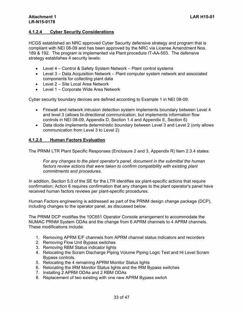
Attachment 1 LAR H15-01 LR-N15-0178
33 of 47
4.1.2.4 Cyber Security Considerations
HCGS established an NRC approved Cyber Security defensive strategy and program that is compliant with NEI 08-09 and has been approved by the NRC via License Amendment Nos. 189 & 192. The program is implemented via Plant procedure IT-AA-503. The defensive strategy establishes 4 security levels:
Level 4 – Control & Safety System Network – Plant control systems Level 3 – Data Acquisition Network – Plant computer system network and associated
components for collecting plant data Level 2 – Site Local Area Network Level 1 – Corporate Wide Area Network
Cyber security boundary devices are defined according to Example 1 in NEI 08-09:
Firewall and network intrusion detection system implements boundary between Level 4 and level 3 (allows bi-directional communication, but implements information flow controls in NEI 08-09, Appendix D, Section 1.4 and Appendix E, Section 6)
Data diode implements deterministic boundary between Level 3 and Level 2 (only allows communication from Level 3 to Level 2)
4.1.2.5 Human Factors Evaluation
The PRNM LTR Plant Specific Responses (Enclosure 2 and 3, Appendix R) Item 2.3.4 states:
For any changes to the plant operator's panel, document in the submittal the human factors review actions that were taken to confirm compatibility with existing plant commitments and procedures.
In addition, Section 5.0 of the SE for the LTR identifies six plant-specific actions that require confirmation; Action 6 requires confirmation that any changes to the plant operator's panel have received human factors reviews per plant-specific procedures. Human Factors engineering is addressed as part of the PRNM design change package (DCP), including changes to the operator panel, as discussed below.
The PRNM DCP modifies the 10C651 Operator Console arrangement to accommodate the NUMAC PRNM System ODAs and the change from 6 APRM channels to 4 APRM channels. These modifications include:
1. Removing APRM E/F channels from APRM channel status indicators and recorders 2. Removing Flow Unit Bypass switches 3. Removing RBM Status indicator lights 4. Relocating the Scram Discharge Piping Volume Piping Logic Test and Hi Level Scram
Bypass controls. 5. Relocating the 4 remaining APRM Monitor Status lights 6. Relocating the IRM Monitor Status lights and the IRM Bypass switches 7. Installing 2 APRM ODAs and 2 RBM ODAs 8. Replacement of two existing with one new APRM Bypass switch

Attachment 1 LAR H15-01 LR-N15-0178
34 of 47
PSEG procedure NC.DE-TS.ZZ-1017 identifies design guidance for incorporating human factors engineering principles into design changes based on the guidance in NUREG-0700. The following design principles are applicable to the changes made by the PRNM DCP:
Functional Grouping Highlight Component Grouping Control Display Integration Legend Pushbutton Guidelines Key-operated Controls Labeling Demarcation
Detailed analysis of compliance with NUREG-0700 will be documented with the completion of the detailed design. The Phase 2 submittal of this PRNM LAR (provided approximately one year after this Phase 1 submittal) will provide a description of the NUREG-0700 compliance. A discussion of the OE assessed to support the PRNM upgrade will also be provided.
4.1.2.6 TSTF-493
PSEG will implement TSTF-493 Option A for the LSSS functions affected by the PRNM upgrade. PSEG has reviewed the model application and safety evaluation (ADAMS ML100710442) and determined it is applicable to HCGS. Using the guidance of Appendix A of TSTF-493, the two Option A notes specified in the TSTF are applied to the channel calibration of the following affected LSSS functions: TS Table 4.3.1.1-1: Function 2. Average Power Range Monitors
a. Neutron Flux- Upscale (Setdown) b. Simulated Thermal Power- Upscale c. Neutron Flux- Upscale
TS Table 4.3.6-1: Function1. Rod Block Monitor
a. Upscale The addition of the two notes to the above functions is discussed in Section 2 of this Attachment 1, and is reflected in the Attachment 2 TS Markup. The first note requires evaluation of channel performance for the condition where the as-found setting for the channel setpoint is outside its as-found tolerance, but conservative with respect to the AV. The channel evaluation verifies that channel performance continues to satisfy safety analysis assumptions and channel performance assumptions within the setpoint methodology. The purpose of the assessment is to ensure confidence in channel performance prior to returning the channel to service. The second note requires that the as-left setting for the channel be returned to within the as-left tolerance of the Nominal Trip Setpoint (NTSP). Where a setpoint more conservative than the
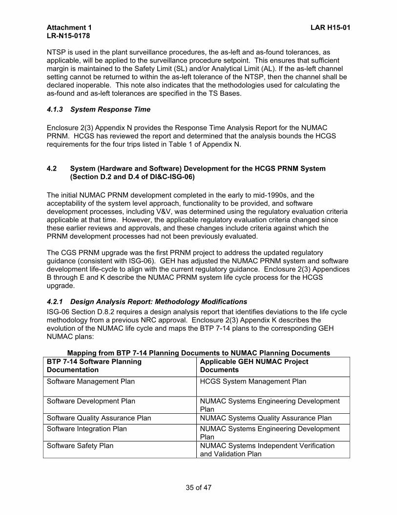
Attachment 1 LAR H15-01 LR-N15-0178
35 of 47
NTSP is used in the plant surveillance procedures, the as-left and as-found tolerances, as applicable, will be applied to the surveillance procedure setpoint. This ensures that sufficient margin is maintained to the Safety Limit (SL) and/or Analytical Limit (AL). If the as-left channel setting cannot be returned to within the as-left tolerance of the NTSP, then the channel shall be declared inoperable. This note also indicates that the methodologies used for calculating the as-found and as-left tolerances are specified in the TS Bases.
4.1.3 System Response Time
Enclosure 2(3) Appendix N provides the Response Time Analysis Report for the NUMAC PRNM. HCGS has reviewed the report and determined that the analysis bounds the HCGS requirements for the four trips listed in Table 1 of Appendix N.
4.2 System (Hardware and Software) Development for the HCGS PRNM System (Section D.2 and D.4 of DI&C-ISG-06)
The initial NUMAC PRNM development completed in the early to mid-1990s, and the acceptability of the system level approach, functionality to be provided, and software development processes, including V&V, was determined using the regulatory evaluation criteria applicable at that time. However, the applicable regulatory evaluation criteria changed since these earlier reviews and approvals, and these changes include criteria against which the PRNM development processes had not been previously evaluated. The CGS PRNM upgrade was the first PRNM project to address the updated regulatory guidance (consistent with ISG-06). GEH has adjusted the NUMAC PRNM system and software development life-cycle to align with the current regulatory guidance. Enclosure 2(3) Appendices B through E and K describe the NUMAC PRNM system life cycle process for the HCGS upgrade.
4.2.1 Design Analysis Report: Methodology Modifications
ISG-06 Section D.8.2 requires a design analysis report that identifies deviations to the life cycle methodology from a previous NRC approval. Enclosure 2(3) Appendix K describes the evolution of the NUMAC life cycle and maps the BTP 7-14 plans to the corresponding GEH NUMAC plans:
Mapping from BTP 7-14 Planning Documents to NUMAC Planning Documents BTP 7-14 Software Planning Documentation
Applicable GEH NUMAC Project Documents
Software Management Plan HCGS System Management Plan
Software Development Plan NUMAC Systems Engineering Development Plan
Software Quality Assurance Plan NUMAC Systems Quality Assurance Plan
Software Integration Plan NUMAC Systems Engineering Development Plan
Software Safety Plan NUMAC Systems Independent Verification and Validation Plan

Attachment 1 LAR H15-01 LR-N15-0178
36 of 47
Software Verification and Validation Plan NUMAC Systems Independent Verification and Validation Plan
Software Configuration Management Plan NUMAC Systems Engineering Development Plan
Software Test Plan NUMAC Systems Independent Verification and Validation Plan
The following plans are also named in BTP 7-14:
• Software Installation Plan • Software Maintenance Plan • Software Training Plan • Software Operations Plan
These plans are not required to be submitted with the Phase 1 submittal; these are required for implementation of the digital system (Phase 3).
The four GEH plans listed in the table jointly define a development program for the HCGS NUMAC digital PRNM system that is consistent with NRC requirements for a high quality development process for software used in safety systems of nuclear power plants. NUREG 0800, Standard Review Plan, Branch Technical Position (BTP) 7-14, Guidance on Software Reviews for Digital Computer-Based Instrumentation and Control Systems, provides acceptance criteria for process planning.
4.2.2 NUMAC System Engineering Development Plan
The NUMAC Systems Engineering Development Plan (Enclosure 2(3) Appendix B) addresses process planning characteristics defined in BTP 7-14 Section B.3.1.2, Software Development Plan; BTP 7-14 Section B.3.1.4, Software Integration Plan; and BTP 7-14 Section B.3.1.11, Software Configuration Management Plan.
4.2.3 NUMAC System Quality Assurance Plan
The NUMAC Systems Quality Assurance Plan (Enclosure 2(3) Appendix C) addresses process planning characteristics defined in BTP 7-14 Section B.3.1.3, Software Quality Assurance Plan.
4.2.4 NUMAC System Independent Verification & Validation Plan
The NUMAC Systems Independent Verification and Validation Plan (Enclosure 2(3) Appendix D) addresses process planning characteristics defined in BTP 7-14 Section B.3.1.9, Software Safety Plan; BTP 7-14 Section B.3.1.10, Software Verification and Validation Plan; and BTP 7-14 Section B.3.1.12, Software Test Plan.
4.2.5 Hope Creek Generating Station NUMAC PRNM System Management Plan
The HCGS NUMAC PRNM System Management Plan(Enclosure 2(3) Appendix E) addresses process planning characteristics defined in BTP 7-14 Section B.3.1.1, Software Management Plan.
4.3 Software Architecture / Design Outputs (Section D.3 of DI&C-ISG-06)
BTP 7-14, Section B.3.3.2 requires a description of the software used in the computer (or platform) and the application software, how the software functions, how the various software components are interrelated, and how the software utilizes the hardware. This information is typically contained in the (a) platform and application software architecture description, (b) the

Attachment 1 LAR H15-01 LR-N15-0178
37 of 47
platform and application software requirements specification, and (c) the platform and application software design specification. The (a) software architecture description is provided in the System Architecture Description document (Enclosure 2(3) Appendix A) as discussed previously in Section 4.1. The following documents describe (b) the software requirements specification and (c) the software design specification.
4.3.1 System Requirements Specification & APRM Performance Specification
The NUMAC PRNM System Requirements Specification (Enclosure 2(3) Appendix F) defines the system requirements for the design and manufacture of a NUMAC based PRNM System. The NUMAC PRNM System is designed to replace the existing APRM and RBM channels in a Neutron Monitoring System (NMS) of a Boiling Water Reactor (BWR) nuclear power plant. The NUMAC PRNM System also provides the OPRM channels required for the detection of reactor instability, the ARTS functions, and the implementation of the 2/4 Logic interface to the Reactor Protection System (RPS).
The NUMAC APRM DSS-CD Performance Specification (Enclosure 2(3) Appendix F)
defines the performance characteristics and application limits for the HCGS NUMAC APRM application which includes the OPRM Detect and Suppress Solution - Confirmation Density (DSS-CD) and automatic Backup Stability Protection (BSP) functions.
4.3.2 APRM Functional Controller System Design Specification
APRM Functional Controller System Design Specification (Enclosure 2(3) Appendix G) comprises the high level design of the NUMAC APRM Functional Controller software. The purpose of this document is twofold:
Define the Functional software design in sufficient detail such that software implementation can be undertaken without need for major design decisions.
Provide a means for understanding how the NUMAC Functional Controller Software fulfills design input requirements.
4.4 Environmental Equipment Qualification (Section D.5 of DI&C-ISG-06)
Documentation of equipment qualification, that confirms that the equipment qualification envelopes plant-specific requirements, is required in the plant-specific license amendment when referencing the previously approved LTR. The equipment qualification activities on the PRNM system comply with IEEE Standard 603 Clause 5.4 (Reference Enclosure 2(3) Appendix O), in accordance with the requirements of IEEE Standard 323 ("IEEE Standard for Qualifying Class 1E Equipment for Nuclear Power Generating Stations," 1983) and the guidance of IEEE Standard 344 ("IEEE Recommended Practices for Seismic Qualification of Class 1E Equipment for Nuclear Power Generating Stations," 2004). The Hope Creek NUMAC PRNM System Qualification Program (Enclosure 2(3) Appendix H) identifies the requirements to which the replacement PRNM system equipment will be qualified. The program provides guidance for the qualification of the replacement PRNM system and direction on whether the equipment is to be qualified by type-testing, by analysis, or by a combination of the two. The replacement PRNM system components are to be qualified based on operating in conditions considered mild-environments in which they are located. The equipment qualification includes temperature, humidity, pressure, radiation, seismic, and electromagnetic compatibility (EMC).

Attachment 1 LAR H15-01 LR-N15-0178
38 of 47
4.5 Defense-In-Depth & Diversity (Section D.6 of DI&C-ISG-06)
BTP 7-19 and DI&C-ISG-028 provide guidance to address diversity and defense-in-depth (D3). The D3 analyses must confirm that vulnerabilities to common-cause failures (CCFs) have been adequately addressed; to provide reasonable assurance that CCFs do not defeat either the protection provided by alternative means (i.e., an independent and diverse safety function) or an echelon of defense that provides defense-in-depth. The Hope Creek NUMAC PRNM Diversity and Defense in Depth Analysis (Enclosure 2(3) Appendix I) provides the HCGS D3 analysis demonstrating compliance with the BTP 7-19 criteria.
4.6 Communications (Section D.7 of DI&C-ISG-06)
Since the prior review and approval of the NUMAC PRNM LTR further NRC staff guidance has been made available that provides evaluation criteria applicable to safety-to-non-safety interfaces of digital inter-channel communication. DI&C-ISG-04, "Task Working Group #4: Highly-Integrated Control Rooms-Communications Issues (HICRc),” provides current guidance on addressing communication issues in three areas:
Interdivisional Communications Command Prioritization Multi-divisional Control and Display Stations
Section 7 of the NUMAC PRNM System Architecture Description (Enclosure 2(3) Appendix A) provides the PRNM communication analysis satisfying the positions in DI&C-ISG-04.
4.7 System, Hardware, Software, and Methodology Modifications (Deviations from the Prior LTRs) (Section D.8 of DI&CISG-06)
A Design Analysis Report is required that identifies deviations to the system, hardware, software, or design lifecycle methodology9 from a previous NRC approval of a digital I&C system or approved topical report. Enclosure 2(3) Appendix J provides the HCGS Design Analysis Report that identifies the deviations to the system, hardware, and software from previous NRC approvals. The “Hope Creek NUMAC PRNM System, Hardware, Software, and Methodology Modifications” Design Analysis Report addresses three specific areas:
Hope Creek deviations from the approved NUMAC PRNM LTR (Reference 1) Hope Creek deviations from the approved GE Boiling Water Reactor DSS-CD LTR
(Reference 2). There are no deviations. HCGS differences from the CGS NUMAC PRNM system that was reviewed and
approved by the NRC (Reference 3). The proposed HCGS system is very similar to the CGS system which is cited as a precedent. Note that consistent with Reference 1.a Section 5.3.5.7 HCGS does have an RRCS output; CGS does not.
4.8 Compliance with IEEE Standard 603 (Section D.9 of DI&C-ISG-06)
Enclosure 2(3) Appendices O, M, L and P discuss how the PRNM System meets the requirements of IEEE Standard 603-1991.
8 ISG-02 is superseded by BTP 7-19 Revision 6 9 Deviations to the design lifecycle methodology are provided in a separate report as discussed in
Section 4.2.1 (Design Analysis Report: [Life Cycle] Methodology Modifications)

Attachment 1 LAR H15-01 LR-N15-0178
39 of 47
4.8.1 Report on Compliance with IEEE Standards (603-1991 and 7-4.3.2-2003) and Theory of Operations Description
Enclosure 2(3) Appendix O. This report discusses how the NUMAC PRNM complies with applicable clauses in IEEE Standard 603-1991 and IEEE Standard 7-4.3.2-2003. The report also provides a discussion on the PRNM Theory of Operations Description (ISG-06 Enclosure B Item 1.20).
4.8.2 Design Report on Computer Integrity, Test and Calibration, and Fault Detection (IEEE Standard 603-1991 Clause 5.5)
Enclosure 2(3) Appendix M. This report addresses DI&C-ISG-06 Sections D.9.4.2.5, D.9.4.2.7, D.9.4.2.10, D.9.4.3.5, D.10.4.2.5, D.10.4.2.5.1, D.10.4.2.5.2, D.10.4.2.5.3 and D.10.4.2.7 for the PRNM System (ISG-06 Enclosure B Item 1.18). Consequently, the report demonstrates compliance with IEEE Standard 603-1991, Clauses 5.5, 5.7, 5.10 and 6.5, and IEEE Standard 7-4.3.2-2003, Clauses 5.5, 5.5.1, 5.5.2, 5.5.3 and 5.7.
4.8.3 Design Analysis Report: Electrical Independence (IEEE Standard 603-1991 Clause 5.6)
Enclosure 2(3) Appendix L. This report addresses DI&C-ISG-06 Section D.9.4.2 (ISG-06 Enclosure B item 1.16); how the PRNM system complies with IEEE Standard 603-1991 Clause 5.6.
4.8.4 Setpoint Methodology and Calculations (IEEE Standard 603-1991 Clause 6.8)
Enclosure 2(3) Appendix P. This report provides the Setpoint Methodology Overview that addresses DI&C-ISG-06 Section D.9.4.3.8 (ISG-06 Enclosure B item 1.21); how the PRNM system complies with IEEE Standard 603-1991 Clause 6.8. The proposed TS changes and TS markups (Section 2.0 and Attachment 2) provide the resulting calculated setpoints10. Appendix P also includes the Instrument Limit Calculation documents (for APRM and RBM) that provide the inputs and calculated setpoint results. The supporting calculations are available for NRC audit; in lieu of submitting the calculations. The data in support of the calculations are contained in large data bases, so it would be difficult to provide the data and it would take more time and resources to review the calculations, if submitted. This is consistent with the approach used for the CGS PRNM upgrade review and approval.
10 As discussed in ISG-06, setpoint calculations are to be provided with the Phase 2 submittal; however
the TS mark-up in this Phase 1 submittal includes the setpoint changes.

Attachment 1 LAR H15-01 LR-N15-0178
40 of 47
4.9 Conformance with IEEE Standard 7-4.3.2 (Section D.10 of DI&C-ISG-06)
Enclosure 2(3) Appendix O discusses how the PRNM system meets the requirements of IEEE Standard 7-4.3-2003. This report discusses how the NUMAC PRNM complies with applicable clauses in IEEE Standard 603-1991 and IEEE Standard 7-4.3.2-2003. This includes discussion of the Software Tool Verification Program (ISG-06 D.10.4.2.3.2), the Software Project Risk Management Program (ISG-06 D.10.4.2.3.6), and the Commercial Grade Dedication Plan (ISG-06 D.10.4.2.4.2). The report also provides a discussion on the PRNM Theory of Operations Description (ISG-06 Enclosure B Item 1.20).
4.10 Secure Development and Operational Environment (Section D.12 of DI&C-ISG-06)
Enclosure 2(3) Appendix Q, “Secure Development and Operational Environment and Vulnerability Assessment Report” addresses secure software development and operation throughout the PRNM product development to ensure the system is reliable (ISG-06 Enclosure B Item 1.27). This report also includes the PRNM system Vulnerability Assessment (ISG-06 Enclosure B Item 1.26).
4.11 Confirmation of Plant-Specific Actions
Section 5.0 of the SE for the NUMAC PRNM LTR (Reference 1a) identifies six plant-specific actions that are required when a licensee references the LTR as part of a license amendment submittal. This section identifies each of these actions and the HCGS confirmation of each action.
(1) Confirm the applicability of the NUMAC PRNM LTR (NEDC-32410P-A), including clarifications and reconciled differences between the specific plant design and the topical report design descriptions.
This license amendment request identifies the specific HCGS PRNM configuration and the general applicability of NEDC-32410P-A. The differences and deviations from the LTR (including differences from the CGS precedent) are provided, and justified, in the System, Hardware, Software, and Methodology Modifications (Deviations from the Prior LTRs) Report (Enclosure 2(3) Appendix J).
(2) Confirm the applicability of the BWROG topical reports that address the PRNM system
and associated instability functions, set points and margins.
The applicability of the BWROG topical reports that address the PRNM system and its associated instability functions, set points and margins is provided in the DSS-CD Evaluation (Enclosure 2(3) Appendix T).
(3) Provide plant-specific revised Technical Specification pages for the PRNM system
functions consistent with NEDC-32410P-A, Appendix H.
The HCGS TS changes are identified and justified in Section 2.0 of this Attachment 1 to the LAR; the marked-up TS are provided in Attachment 2 of this submittal.
(4) Confirm the plant-specific environmental conditions are enveloped by the PRNM system
equipment qualifications values.

Attachment 1 LAR H15-01 LR-N15-0178
41 of 47
The evaluation of HCGS specific environmental conditions and qualification is provided in the NUMAC Power Range Neutron Monitor System Qualification Program - Hope Creek Generating Station (Enclosure 2(3) Appendix H).
(5) Confirm that administrative controls are provided for manually bypassing APRM/OPRM
channels or protective functions, and for controlling access to the panel and the APRM/OPRM channel bypass switch.
The Phase 2 submittal of this PRNM LAR (provided approximately one year after this Phase 1 submittal) will provide confirmation of this action (as discussed in Section 4.1.2.5 above).
(6) Confirm that any changes to the plant operator's panel have received human factors
reviews per plant-specific procedures.
The Phase 2 submittal of this PRNM LAR (provided approximately one year after this Phase 1 submittal) will provide confirmation of this action (as discussed in Section 4.1.2.5 above).

Attachment 1 LAR H15-01 LR-N15-0178
42 of 47
5.0 REGULATORY ANALYSIS
The PRNM upgrade incorporates redundancy, independence, and diversity while providing simplified management and maintenance of the system. The effect of the PRNM upgrade on TS and accident analyses has been evaluated. Appropriate setpoints have been evaluated for the new system and the TS accordingly revised. The required Defense-in-Depth and Diversity (D3) report has been prepared confirming that vulnerabilities to common-cause failures (CCFs) have been adequately addressed. The hardware and software development for the PRNM upgrade process complies with the Institute of Electrical and Electronics Engineers (IEEE) Standard 603-1991 Clause 5.3 "Quality," and IEEE Standard 7-4.3.2-2003 Clause 5.3 "Quality," including the digital system development life cycle, in order to provide a high quality and well defined development process. The independent V&V effort for the upgrade utilizes a process and activities that comply with IEEE Standard 7-4.3.2-2003 Clause 5.3.3, "Validation and Verification" to ensure the upgrade meets required specified functional requirements and criteria. Finally, the Software configuration management used for the upgrade complies with IEEE Standard 7-4.3.2-2003 Clause 5.3.5, "Software Configuration Management," control the system and programming throughout its development and use. Therefore, PSEG concludes the proposed PRNM upgrade complies with the 10 CFR 50 regulations and associated regulatory guidance.
5.1 Applicable Regulatory Requirements/Criteria
The following regulations and guidance are applicable to the proposed installation of the GEH NUMAC PRNM equipment:
10 CFR 50.36, "Technical Specifications."
Paragraph 10 CFR 50.55a(a)(1), states that Structures, Systems, and Components must be designed, fabricated, erected, constructed, tested, and inspected to quality standards commensurate with the importance of the safety function to be performed.
Paragraph 10 CFR 50.55a(h), "Protection and safety systems," approves the 1991
version of IEEE Standard 603, "IEEE Standard Criteria for Safety Systems for Nuclear Power Generating Stations," for incorporation by reference including the correction sheet dated January 30, 1995.
The following General Design Criteria (GDC) in Appendix A to 10 CFR Part 50:
GDC 1, "Quality standards and records" GDC 2, "Design bases for protection against natural phenomena" GDC 4, "Environmental and dynamic effects design bases" GDC 10, "Reactor design" GDC 12, "Suppression of reactor power oscillations" GDC 13, "Instrumentation and control" GDC 15, "Reactor coolant system design" GDC 19, “Control Room” GDC 20, "Protection system functions"

Attachment 1 LAR H15-01 LR-N15-0178
43 of 47
GDC 21, "Protection system reliability and testability" GDC 22, "Protective system independence" GDC 23, "Protection system failure modes" GDC 24, "Separation of protection and control systems" GDC 25, "Protection system requirements for reactivity control malfunctions" GDC 29, "Protection against anticipated operational occurrences"
Regulatory Guide 1.75, Revision 3, "Criteria for Independence of Electrical Safety
Systems," February 2005 (ADAMS Accession No. ML043630448).
Regulatory Guide 1.100, Revision 3, "Seismic Qualification of Electrical and Active Mechanical Equipment and Functional Qualification of Active Mechanical Equipment for Nuclear Power Plants," September 2009 (ADAMS Accession No. ML091320468).
Regulatory Guide 1.105, Revision 3, "Setpoints for Safety Related Instrumentation,"
December 1999 (ADAMS Accession No. ML993560062).
Regulatory Guide 1.152, Revision 3, "Criteria for Use of Computers in Safety Systems of Nuclear Power Plants," July 2011 (ADAMS Accession No. ML102870022).
Regulatory Guide 1.168, Revision 2, "Verification, Validation, Reviews, and Audits for
Digital Computer Software Used in Safety Systems of Nuclear Power Plants," July 2013 (ADAMS Accession No. ML13073A210).
Regulatory Guide 1.169, Revision 1, "Configuration Management Plans for Digital
Computer Software Used in Safety Systems of Nuclear Power Plants," July 2013 (ADAMS Accession No. ML12355A642).
Regulatory Guide 1.170, Revision 1, "Software Test Documentation for Digital Computer
Software Used in Safety Systems of Nuclear Power Plants," July 2013 (ADAMS Accession No. ML13003A216).
Regulatory Guide 1.171, Revision 1,"Software Unit Testing for Digital Computer
Software Used in Safety Systems of Nuclear Power Plants," July 2013 (ADAMS Accession No. ML13004A375).
Regulatory Guide 1.172, Revision 1 "Software Requirements Specifications for Digital
Computer Software and Complex Electronics Used in Safety Systems of Nuclear Power Plants," July 2013 (ADAMS Accession No. ML13007A173).
Regulatory Guide 1.173, Revision 1 "Developing Software Life-Cycle Processes for
Digital Computer Software Used in Safety Systems of Nuclear Power Plants," July 2013 (ADAMS Accession No. ML13009A190).
Regulatory Guide 1.180, Revision 1, "Guidelines for Evaluating Electromagnetic and
Radio-Frequency Interference in Safety-Related Instrumentation and Control Systems," October 2003 (ADAMS Accession No. ML032740277).

Attachment 1 LAR H15-01 LR-N15-0178
44 of 47
Regulatory Guide 1.209, "Guidelines for Environmental Qualification of Safety-Related Computer-Based Instrumentation and Control Systems in Nuclear Power Plants," March 2007 (ADAMS Accession No. ML070190294).
DI&C-ISG-04, Revision 1, "Task Working Group #4: Highly-Integrated Control Rooms-
Communications Issues (HICRc)," March 2007 (ADAMS Accession No. ML083310185).
DI&C-ISG-06, “Task Working Group #6: Licensing Process,” Revision 1, dated January 19, 2011 (ADAMS ML110140103).
The applicable portions of the following branch technical positions within NUREG-0800, Standard Review Plan for the Review of Safety Analysis Reports for Nuclear Power Plants: LWR Edition" (SRP), Chapter 7, "Instrumentation and Controls," as follows:
Branch Technical Position 7-11, "Guidance on Application and Qualification of Isolation Devices"
Branch Technical Position 7-12, "Guidance on Establishing and Maintaining Instrument Setpoints"
Branch Technical Position 7-14, "Guidance on Software Reviews for Digital Computer-Based Instrumentation and Control Systems"
Branch Technical Position 7-19, "Guidance for Evaluation of Diversity and Defense-In-Depth in Digital Computer-Based Instrumentation and Control Systems"
Branch Technical Position 7-21, "Guidance on Digital Computer Real-Time Performance"
5.2 No Significant Hazards Consideration
In accordance with 10 CFR 50.90, PSEG Nuclear LLC (PSEG) requests an amendment to Renewed Facility Operating License No. NPF-57 for Hope Creek Generating Station (HCGS). The proposed license amendment request (LAR) would reflect the installation of the General Electric-Hitachi (GEH) digital Nuclear Measurement Analysis and Control (NUMAC) Power Range Neutron Monitoring (PRNM) system. The planned upgrade will replace the existing analog Average Power Range Monitor (APRM) sub-system of the existing Neutron Monitoring System with the more reliable, digital NUMAC PRNM System. The system upgrade incorporates the Oscillation Power Range Monitor (OPRM) function and the transition from flow-biased to power biased Rod Block Monitor (RBM). The following Technical Specifications (TS) sections are affected by this change:
• TS 2.2 Limiting Safety System Settings • TS 3/4.1.4.3 Rod Block Monitor • TS 3/4.3.1 Reactor Protection System Instrumentation • TS 3/4.3.6 Control Rod Block Instrumentation • TS 3/4.3.11 Oscillation Power Range Monitor • TS 3/4.4.1 Recirculation System • TS 6.9.1.9 Core Operating Limits Report • TS 6.9.3 Special Reports

Attachment 1 LAR H15-01 LR-N15-0178
45 of 47
PSEG has evaluated whether a significant hazards consideration is involved with the proposed amendment by focusing on the three conditions set forth in 10 CFR 50.92, "Issuance of amendment," as discussed below: 1. Does the proposed amendment involve a significant increase in the probability or
consequences of an accident previously evaluated? Response: No. The probability of accidents occurring is not affected by the PRNM system, as the PRNM system is not the initiator of any accident and does not interact with equipment whose failure could cause an accident. The transition from flow-biased to power-biased RBM does not increase the probability of an accident; the RBM is not involved in the initiation of any accident. The regulatory criteria established for the APRM, OPRM, and RBM systems will be maintained with the installation of the upgraded PRNM system. Therefore, the proposed change does not involve a significant increase in the probability of an accident previously evaluated. The consequences of accidents are not affected by the PRNM system, as the setpoints in the PRNM system will be established so that all analytical limits are met. The unavailability of the new system will be equal to or less than the existing system and, as a result, the scram reliability will be equal to or better than the existing system. No new challenges to safety-related equipment will result from the PRNM system modification. The change to power biased RBM allows for Rod Withdrawal Error (RWE) analyses performed for each future reload to take credit for rod blocks during the rod withdrawal transients. The results of the RWE event analysis will be used in establishing the cycle specific operating limits for the fuel. The proposed change will also replace the currently installed and NRC approved Asea Brown Boveri (ABB) OPRM Option III long-term stability solution with an NRC approved General Electric-Hitachi (GEH) Detect and Suppress Solution - Confirmation Density (DSS-CD) stability solution (reviewed and approved by the NRC in Reference 2, Licensing Topical Report). The OPRM meets the GDC 10, "Reactor Design," and 12, "Suppression of Reactor Power Oscillations," requirements by automatically detecting and suppressing design basis thermal hydraulic oscillations to protect specified fuel design limits. Therefore, the proposed change does not involve a significant increase in the consequences of an accident previously evaluated. Therefore, the proposed change does not involve a significant increase in the probability or consequences of an accident previously evaluated.
2. Does the proposed amendment create the possibility of a new or different kind of accident from any accident previously evaluated?
Response: No. The components of the PRNM system will be supplied to equivalent or better design and qualification criteria than is currently required for the plant. Equipment that could be affected by PRNM system has been evaluated. No new operating mode, safety-related equipment lineup, accident scenario, or system interaction mode was identified. Therefore, the upgraded PRNM system will not adversely affect plant equipment.

Attachment 1 LAR H15-01 LR-N15-0178
46 of 47
The new PRNM system uses digital equipment that has software controlled digital processing points and software controlled digital processing compared to the existing PRNM system that uses mostly analog and discrete component processing (excluding the existing OPRM). Specific failures of hardware and potential software common cause failures are different from the existing system. The effects of potential software common cause failure are mitigated by specific hardware design and system architecture as discussed in Section 6.0 of the NUMAC PRNM LTR, and supported by a plant specific evaluation. The transition from a flow-biased RBM to a power dependent RBM does not change its function to provide a control rod block when specified setpoints are reached. The change does not introduce a sequence of events or introduce a new failure mode that would create a new or different type of accident. Failure(s) of the system have the same overall effect as the present design. No new or different kind of accident is introduced. Therefore, the PRNM system will not adversely affect plant equipment. The currently installed APRM System is replaced with a NUMAC PRNM system that performs the existing power range monitoring functions and adds an OPRM to react automatically to potential reactor thermal-hydraulic instabilities. Therefore, the proposed change does not create the possibility of a new or different kind of accident from any previously evaluated.
3. Does the proposed amendment involve a significant reduction in a margin of safety?
Response: No. The proposed TS changes associated with the NUMAC PRNM system implement the constraints of the NUMAC PRNM system design and related stability analyses. The NUMAC PRNM system change does not impact reactor operating parameters or the functional requirements of the PRNM system. The replacement equipment continues to provide information, enforce control rod blocks, and initiate reactor scrams under appropriate specified conditions. The power dependent RBM will continue to prevent rod withdrawal when the power-dependent RBM rod block setpoint is reached. The MCPR and Linear Heat Generation Rate (LHGR) thermal limits will be developed on a cycle specific basis to ensure that fuel thermal mechanical design bases remain within the licensing limits during a control rod withdrawal error event and to ensure that the MCPR SL will not be violated as a result of a control rod withdrawal error event. The proposed change does not reduce safety margins. The replacement PRNM equipment has improved channel trip accuracy compared to the current analog system, and meets or exceeds system requirements previously assumed in setpoint analysis. The power dependent RBM will support cycle specific RWE analysis ensuring fuel limits are not exceeded. Thus, the ability of the new equipment to enforce compliance with margins of safety equals or exceeds the ability of the equipment which it replaces. Therefore, the proposed change does not involve a significant reduction in a margin of safety.
Based on the above, PSEG concludes that the proposed amendment does not involve a significant hazards consideration under the standards set forth in 10 CFR 50.92(c), and, accordingly, a finding of no significant hazards consideration is justified.

Attachment 1 LAR H15-01 LR-N15-0178
47 of 47
5.3 Conclusions
In conclusion, based on the considerations discussed above, (1) there is reasonable assurance that the health and safety of the public will not be endangered by operation in the proposed manner, (2) such activities will be conducted in compliance with the Commission's regulations, and (3) the issuance of the amendment will not be inimical to the common defense and security or to the health and safety of the public.
6.0 ENVIRONMENTAL CONSIDERATION
A review has determined that the proposed amendment would change a requirement with respect to installation or use of a facility component located within the restricted area, as defined in 10 CFR 20, or would change an inspection or surveillance requirement. However, the proposed amendment does not involve (i) a significant hazards consideration, (ii) a significant change in the types or a significant increase in the amounts of any effluent that may be released offsite, or (iii) a significant increase in individual or cumulative occupational radiation exposure. Accordingly, the proposed amendment meets the eligibility criterion for categorical exclusion set forth in 10 CFR 51.22(c)(9). Therefore, pursuant to 10 CFR 51.22(b), no environmental impact statement or environmental assessment need be prepared in connection with the proposed amendment.
7.0 REFERENCES
1.
a. GE Nuclear Energy, Nuclear Measurement Analysis and Control Power Range Neutron Monitor (NUMAC PRNM) Retrofit Plus Option III Stability Trip Function, NEDC-32410P-A, Volume 1, dated October 1995.
b. GE Nuclear Energy, Nuclear Measurement Analysis and Control Power Range Neutron Monitor (NUMAC PRNM) Retrofit Plus Option III Stability Trip Function, NEDC-32410P-A, Volume 2, dated October 1995.
c. GE Nuclear Energy, Nuclear Measurement Analysis and Control Power Range Neutron Monitor (NUMAC PRNM) Retrofit Plus Option III Stability Trip Function, NEDC-32410P-A, Supplement 1, dated November 1997.
2. GE Hitachi Boiling Water Reactor Detect and Suppress Solution-Confirmation Density,
NEDC-33075P-A, Revision 8, November 2013. 3. Columbia Generating Station – Issuance of Amendment RE: Implementation of Power
Range Neutron Monitoring/Average Power Range Monitor/Rod Block Monitor/Technical Specifications/Maximum Extended Load Line Limit Analysis (PRNM/ARTS/MELLLA) (TAC NO. ME7905) (ADAMS ML ML13317B623, Non-Proprietary).

Attachment 2 LAR H15-01 LR-N15-0178
Mark-up of Proposed Technical Specification Pages The following Technical Specifications pages for Renewed Facility Operating License NPF-57 are affected by this change request: Technical Specification Page Index x, xvii, xviii 2.2, “Limiting Safety System Settings” 2-4 3/4.1.4.3, “Rod Block Monitor” 3/4 1-18 3/4.3.1, "Reactor Protection System Instrumentation" 3/4 3-1, 2, 4, 5, 7 and 8 3/4.3.6, “Control Rod Block Instrumentation” 3/4 3-57, 58, 59, 60 and 61 3/4.3.11, “Oscillation Power Range Monitor” 3/4 3-110 3/4.4.1, “Recirculation System” 3/4 4-1 and 4-2 6.9.1.9, “Core Operating Limits Report” 6-20 6.9.3, “Special Reports” 6-21

INDEX
LIMITING CONDITIONS FOR OPERATION AND SURVEILLANCE REQUIREMENTS
S E CTION Table 3 . 3 . 9 - 2 FeedwateriMain Turbine Trip Sys tem
Actuation Inst rumentation Setpoints . . . 3 14 3 - 1 0 7
Table 4 . 3 . 9 . 1 - 1 FeedwateriMain Turbine Trip Sys tem Actuation Ins t rumentat ion survei l l ance Requirements . . . . . . . . . . . . . . • . . . . . • . . . . . 3 14 3 - 1 0 8
3 14 . 3 . 1 0 MECHANICAL VACUUM PUMP TRIP INSTRUMENTATION . • . . . . . • . . . . . . 3 14 3 - 1 0 9
3 I 4 • 3 . 1 1 OSC-4-L-LA.!F-I-ON-POWER--RANGE MONmR ·I Deleted - � . . . . . . . . . . . . . . . . 3 I 4 3 - 1 1 o
3 1 4 . 4 REACTOR COOLANT SYSTEM
3 1 4 . 4 . 1 RECIRCULATION SYSTEM
Recirculation Loops . . . . • . . . . • • • . . . . • . . . . . • . • . • • • . . . . . . . . • 3 1 4 4 - 1
Figure 3 . 4 . 1 . 1 - 1 DELETED . . . . . . . . . . . . . . . . .. . . . . . . . . . . . . . 3 1 4 4 - 3 Jet Pumps . . . . . . . . . . • • . . . . . . . . . . • . . . . . . . . . . • . . . . . . . . • . . . . , 3 14 4 - 4 Recirculat ion Loop Flow . . . . • . . . . . • . . . . . . . . . . . . • . . . . . . . . . , 3 / 4 4 - 5 Idle Recircu l a t ion Loop S tartup . . • • . . . . . . . . • . . . • . . . . . . . . • 3 /4 4 H 6
3 14 . 4 . 2 SAFETY/RELIEF VALVES
Safe ty/Re l i e f Valves . . • . . . . . . • . . . . . . . . . . • • . • . . . . • . . • . . . . . 3 14 4 - 7 Safety/Re l i e f Valves Low-Low Set Function . . . . • . . . . . . . . . . . 3 / 4 4 - 9
3 /4 . 4 . 3 REACTOR COOLANT SYSTEM LEAKAGE
Leakage Det e c t ion Sys tems . . . . . . . . . • . . . . . . . . . . . . . . . . . . . . . . 3 / 4 4 - 10 Operational Leakage . . . . • . . . . . . . . . . . . . . . . . . . . . . . . . . . . . . . . . 3 / 4 4 - 1 1
Table 3 . 4 . 3 . 2 - 1 Reactor Coolant System Pres sure Isolation Valves . . . . . . . . . . . . . • • . . . . • . . 3 / 4 4 - 13
Table 3 . 4 . 3 . 2 - 2 Reactor Coolant System Interf ace Valves Leakage Pres sure Monitors . . • . . . 3/4 4 - 14
3 I 4 • 4 • 4 DELETED • . . . . . . . . . . . . • . . . . . • • . . . . . . . . . . . . . • . . . . • . . . . . . • . . . 3 I 4 4 - 15
3 /4 . 4 . 5 S PECI FIC ACTIVITY . . . . . . . . . . • . . . . . . . . . . . . • . . . . . • . . . . . . . . . . 3 / 4 4 - 18
Table 4 . 4 . 5 - 1 Primary Coolant Speci f i c Act ivi ty Sample and Analysis Program . . . . . . . . . . . . . . . . . . 3 / 4 4 - 2 0
HOPE CREEK :X: Amendment No . 1 59

INDEX
BASES
SECTION PAGE
3 / 4 . 0 APPLICAB ILITY . . . . . . . . . . . . . . . . . . . . . . . . . . . . . . . . . . . . . . . . . . . . . . . . B 3 / 4 0 - 1
3 / 4 . 1 REACTIVITY CONTROL SYSTEMS
3 / 4 . 1 . 1 SHUTDOWN MARG IN . . . . . . . . . . . . . . . . . . . . . . . . . . . . . . . . . . . . . B 3 / 4 1 - 1
3 / 4 . 1 . 2 REACTIVITY ANOMALI E S . . . . . . . . . . . . . . . . . . . . . . . . . . . . . . . . B 3 / 4 1 - 1
3 / 4 . 1 . 3 CONTROL RODS . . . . . . . . . . . . . . . . . . . . . . . . . . . . . . . . . . . . . . . . B 3 / 4 1 - 2
3 / 4 . 1 . 4 CONTROL ROD PROGRAM CONTROLS . . . . . . . . . . . . . . . . . . . . . . . . B 3 / 4 1 - 3
3 / 4 . 1 . 5 STANDBY L I QUID C ONTROL SYSTEM . . . . . . . . . . . . . . . . . . . . . . . B 3 / 4 1 - 4
3 / 4 . 2 POWER D I STRIBUTION L IMITS
3 / 4 . 2 . 1 AVERAGE PLANAR LINEAR HEAT GENERATION RATE . . . . . . . . . . B 3 / 4 2 - 1
3 / 4 . 2 . 2 DELETED . . . . . . . . . . . . . . . . . . . . . . . . . . . . . . . . . . . . . . . . . . . . . B 3 / 4 2 - 1
3 / 4 . 2 . 3 MINIMUM CRITICAL POWER RAT IO . . . . . . . . . . . . . . . . . . . . . . . . B 3 / 4 2 - 2
3 / 4 . 2 . 4 L INEAR HEAT GENERATION RATE . . . . . . . . , . . . . . . . . . . . . . . . . B 3 / 4 2 - 3
3 / 4 . 3 INSTRUMENTATI ON
3 / 4 . 3 . 1 REACTOR PROTEC T I ON SYSTEM INSTRUMENTATION . . . . . . . . . . . B 3 / 4 3 - 1
3 / 4 . 3 . 2 I SOLAT I ON ACTUAT ION INSTRUMENTATION . . . . . . . . . . . . . . . . . B 3 / 4 3 - 2
3 / 4 . 3 . 3 EMERGENCY CORE C OOLING SYSTEM ACTUATION
INSTRUMENTAT I ON . . . . . . . . . . . . . . . . . . . . . . . . . . . . . . . . . . . . . B 3 / 4 3 - 2
3 / 4 . 3 . 4 REC IRCULATI ON PUMP TRIP ACTUATI ON
INSTRUMENTAT I ON . . . . . . . . . . . . . . . . , . . . . . . . . . . . . . . . . . . . . B 3 / 4 3 - 3
3 / 4 . 3 . 5 REACTOR CORE I S OLAT ION COOLING SYSTEM ACTUATION
INSTRUMENTAT I ON . . . . . . . . . . . . . . . . . . . . . . . . . . . . . . . . . . . . . B 3 / 4 3 - 4
3 / 4 . 3 . 6 CONTROL ROD BLOCK INSTRUMENTATI ON . . . . . . . . . . . . . . . . . . . B 3 / 4 3 - 4
3 / 4 . 3 . 7 MONITORING INSTRUMENTATION
@] Radi a t i on Mon i t or ing Instrumentat i on . . . . . . . . . . . . . . . . B 3 / 4 3 -4
HOPE CREEK xvi i Amen&nent No . . l63

INDEX
BASES
SECTION PAGE
INSTRUMENTATION ( Cont i nued)
Remot e Shutdown Monitoring Ins trumentat i on and Contro l s . . . . . . . . . . . . . . . . . . . . . . . . . . . . . . . . . . . . . . . . . . . . B 3 / 4 3 - 5
Accident Mon i toring Instrumentat ion . . . . . . . . . . . . . . . . . . . . . . B 3 / 4 3 - 5 Source Range Monitors . . . . . . . . . . . . . . . . . . . . . . . . . . . . . . . . . . . . B 3 / 4 3 - 5
3 / 4 . 3 . 8 DELETED . . . , . . . . . . . • . . . . . . . . . . . . . . . . . . . . . . . . . . . . . . . . . . . . . . B 3 / 4 3 - 7
3 / 4 . 3 . 9 FEEDWATER/MAIN TURBINE TRIP SYSTEM ACTUATION
INSTRUMENTATI ON . . . . . . . . . . . . . . . . . . . . . . . . . . . . . . . . . . . . . . . . . . B 3 / 4 3 - 7
Figure B3 / 4 3 - 1 Reactor Ves sel Water Level . . . . . . . . . . . . . . B 3 / 4 3 - 8
3 / 4 . 3 . 1 0 MECHANICAL VACUUM PUMP TRIP INSTRUMENTATION . . . . . . • . . . . . . . B 3 / 4 3 - 9
3 / 4 . 3 . 1 1 OS€ILLNPION -rewER -MNGE MONITCffl: jDeleted � . . . . . . . . . . • . . . . . B 3 / 4 3 - 13
3 / 4 . 4 REACTOR COOLANT SYSTEM
3 / 4 . 4 . 1 RECIRCULATION SYSTEM . . . . . . . . . . . . . . . . . . . . . . . . . . . . . . . . . . . . . B 3 / 4 4 - 1
3 / 4 . 4 . 2 SAFETY / RELIEF VALVES . . . . . . . . . . . . . . . . . . . . . . . . . . . . . . . . . . . . . B 3 /4 4 - 2
3 / 4 . 4 . 3 REACTOR COOLANT SYSTEM LEAKAGE
Leakage De t ec t i on Sys tems . . . . . . . . . . . . . . . . . . . . . . . . . . . . . . . . B
Operational Leakage . . . . . . . . . . . . . . . . . . . . . . . . . . . . . . . . . . . . . • B
3 / 4 . 4 . 4 CHEMISTRY . . . . . . . . . . . . . . . . . . . . . . . . . . . . . . . . . . . . . . . . . • . • . . . . B
3 / 4 . 4 . 5 SPECIFIC ACTIVITY . . . . . . . . . . . . . . . . . . . . . . . . . . . . . . . . . . . . . . . . B
3 / 4 . 4 . 6 PRESSURE / TEMPERATURE LIMITS . . . . . . . . . . . . . . . . . . . . . . . . . . . . . . B
Table B3 / 4 . 4 . 6 - l Reactor Vessel Toughne s s . . . . . . . . . • . . . . . B
Figure B3 / 4 . 4 . 6 - 1 Fast Neutron Fluence ( E>lMev) at ( 1 / 4 ) T as a
3 / 4 4 - 3 3 / 4 4 - 3
3 / 4 4 - 3
3 / 4 4 - 4
3 / 4 4 - 5
3 / 4 4 - 7
Funct ion of Service l i fe . . . . . . . . . . . . . . . B 3 / 4 4 - 8
Table B3 / 4 . 4 . 6 - 2 Numeric Values for Pres sure / Temperature Limi ts . . . . . . . • . . . . B 3 / 4 4 - 9
HOPE CREEK xvi i i Amendment No . 1 64

; "
NA
See CORE OPERATING LI M ITS REPORT
TABLE 2 . 2 .. 1 - 1
REACTOR PROTECTION SYSTEM INSTRUMENTATION SETPOINTS
FUNCTIONAL UNIT
1 . Intermediate Range Monitor, Neutron FluX-High
2 . Average Power Range Monitor :
a . Neutron Flux-UpscalejTIS etdownill
TRIP SETPOINT
� - 12 0 / 1 2 5 divisions of full scale
[IT] $ H% of RATED THERMAL POWER
Flew Biased S imulated Thermal Power-Up s c ale b .
� � 1 ) Flow Biased
2 ) High Flow Clamped
c . ·P:bred Neutron Flux-Upscale
d . Inoperative
3 . Reactor Ves s e l Steam Dome Pressure - High
4 . React or Ves s e l Water Level - Low, Level 3
5 . Main Steam Line Isolat ion Valve - Closure
*See Bases Figure B 3 /4 3 � 1 .
� 0 . 5 7 ( w-Llw) + _5-8 % * * with a maximum o f
� -1 1 3 . 5 %" o f RATED THERMAL POWER
1 1 1 6 .3 1 � - riB * of RATEP THERMAL POWER
NA
� 1 0 3 7 p s ig
� 1 2 . 5 inches above instrument zero*
� 8% closed
NA
NA
ALLOWABLE VALUES
� 1 2 2 / 1 2 5 divi s ions of full s c a l e
$ 1 9 % of RATED THERMAL POWER
$ 0 . 5 7 ( w-Llw) + _ 6 1 % * * with a maximum o f
� 1 1 5 . 5 % of RATED THERMAL POWER
1 1 1 8 .31 � � % of RATED
THERMAL POWER
N,A
� 1 0 5 7 psig
2 1 1 . 0 inches above instrument · z ero
� 1 2 % closed
* *The Average Power Range Monitor Scram funct ion varies a s a function of rec i rcula t i on loop drive flow (w) . · �w is def ined as the di f ference in indicat ed drive flow ( in percent of drive flow which produces rated core f l ow) between two loop and s ingle loop operat ion at the same core f l ow . Llw = 0 for two rec ircul at ion l oop operat i on . Llw = �% for s ing\e recirculat i on loop operation .
1 1 0 .6 1 2 -4 Amendment No .1 7 4
(a) When the Automated BSP Scram Regions Setpoints are implemented i n accordance with Action 1 0 of Table 3.3 . 1 -1 , the Simulated Thermal Power-Upscale Flow Biased Setpoint wil l be adjusted per the CORE OPERATI N G L I MITS REPORT
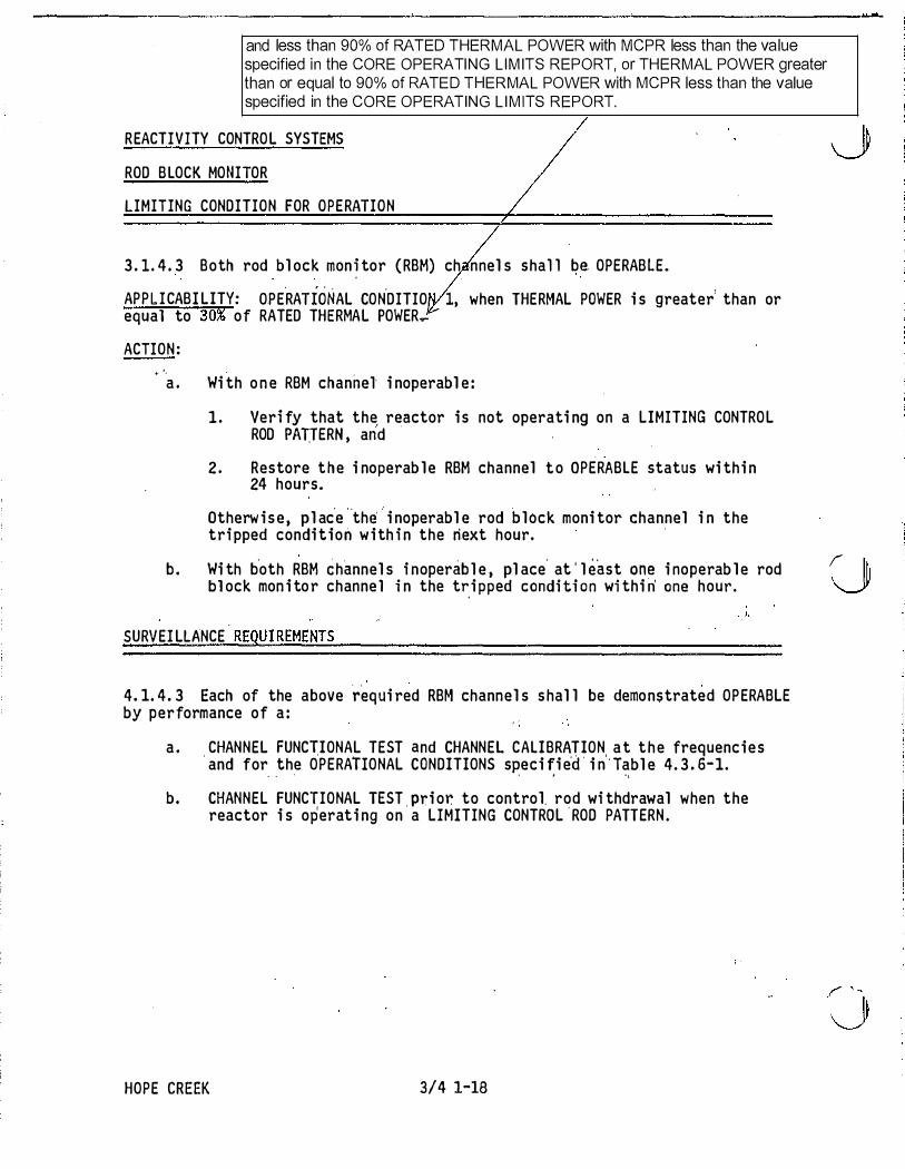
and less than 90% of RATED THERMAL POWER with MCPR less than the value specified in the CORE OPERATING L IM ITS REPORT, or THERMAL POWER greater than or equal to 90% of RATED THERMAL POWER with MCPR less than the value specified in the CORE OPERATING L IM ITS REPORT.
REACTI VITY CONTRO L SYSTEMS
ROD B LOCK MONITOR
LIMITING CONDITION FOR O P E RATI O N
3 . 1. 4 . 3 Both rod bl ock mon � tor ( RBM) ch nnel s shal l be OPERAB LE.
APP L I CABI LITY: OPE.RATIONAL CON.DITIO 1, when THERMAL POWER i s greater' than or
equal to 30% of RATED THERMAL POWER�
ACTION : . •.
a . Wi th o n e RBM channel i noperabl e :
1 . Veri fy that the. re.actor i s not operati ng on a LIMITING CONTRO L ROD PADERN , and
2 . Restore t h e i noperab l e RBM channel t o OPERABLE status wi th i n 24 hours.
Otherw i s e , pl ac'e "the' ' i noperabl e rod b l ock moni tor channel i n the tri pped condi tion w i th i n the next hour. ·
b . Wi th b'oth RBM channel s i noperab l e , pl ace' at ' l east o n e i noperab l e rod I lh bl ock mon i to r channe l i n the t�i pped condi ti o n wi thi ri one hour. �
. l.
SURVEI LLANCE REQUI REMENTS
4. 1. 4 . 3 Each of the above ��qui red RBM channel s s hal l be demo nstrated OP ERABLE by performance of a :
a . . CHANNEL FUNCTIONAL TEST and CHANNEL CALI BRAT ION, a t t h e frequenc i e s and for the OPERATIONAL CONDITIONS speci fi e·d · i n ' Tabl e 4. 3 . 6-1. ' ' I ' L
b. CHANNEL FUNCTIONAL TEST . Pri or. to control rod wi thdrawal when the reactor i s operat i ng on a LIMITING CONTROL ' ROD PATTERN .
HOPE CREEK 3/4 1-18

3/4. 3 1 NSTRUM ENTATION 3/4-4-.3. 1 REACTOR PROTECTION SYSTEM I NSTRUMENTATION
UMIIlNG CONDITION FOR OPEBATION
3.3 . 1 As a min imum, the reactor protection system instrumentation channels shown in Table 3.3. 1 -1 shal l be OPERABLE. Functional Unit 2 . a, 2 . b, 2 .c, 2.d, and 2 .f do not require separate
LOGIC SYSTEM FUNCTIONAL TESTS. The LOGIC SYSTEM
APPLICABILITY:
ACTION:
As shown in Table 3 . 3. 1 -1 . FUNCTIONAL TEST for APRM Function 2 . e includes simulating
APRM and OPRM trip conditions at the APRM channel inputs to
the voter channel to check al l combinations of two tripped inputs
a.
b.
to the 2-0ut-Of-4 voter logic in the voter channels.
With the number of OPERABLE channe s ess t an reqU ire y e 1n 1mum OPERABLE Channels per Trip System requirement for one trip system, place the inoperable channel{s) and/or that trip system� the�ped condition* withi n twelve hours.
�
With the number of OPERABLE channels less than requ ired by the Minimum OPERABLE Channels per Trip System requirement for both trip systems, place at least one trip system** in the tripped condition within one hour and take the ACTION required by Table 3.3 . 1 -1 .
SURVELLLANCE REQUIREMENTS
4 . 3 . 1 . 1 Each reactor protection system instrumentation channel shal l be demonstrated OPERABLE by the performance of the CHANNEL CHECK, CHANNEL F U N CTIONAL TEST and CHANN EL CAL I BRATION operations for the OPERATIONAL CONDITIO NS and at the frequencies shown in Table 4.3 . 1 . 1 - 1 .
4 .3 . 1 .2 LOGIC SYSTEM FUNCTIONAL TESTS and simulated automatic operation of all channels s hall be performed in accordance with the Surveil lance Frequency Control Program.
4.3 . 1 .3 The REACTOR PROTECTION SYSTEM RESPONSE TIME of each reactor trip functional unit shal l be demonstrated to be within its l imit in accordance with the Survei l lance Frequency Control Prog ram. Neutron detectors are exempt from response time testing. For the Reactor Vessel Steam Dome Pressure - H igh Functional Unit and the Reactor Vessel Water Level - Low, Level 3 Functional Unit, the sensor Is elim inated from response time testing for RPS circu its.
4.3 . 1 .4 The provisions of Specification 4.0.4 are not applicable for entry into OPERATIONAL CON DITION 2 or 3 from OPERATIONAL CON DITION 1 for the I nter-mediate Range Monitors.
*
**
An inoperable channel need not be placed in the tripped condit ion where th is would cause the Trip Function to occur. In these cases, the inoperable channel shall be restored to OPERABLE status within 6 hours or the ACTION requ ired by Table 3.3. 1 � 1 for that Trip Function sha l l be taken.
If more channels are i noperable in one trip system than in the other, place the trip system with more inoperable channels in the tripped condition , except when this would cause the Trip Function to occur. Note, Action b. is not appl icable for Functional Un it
� �2_.a_,_2_.b_, _2_.c_, 2_._d_, a_n_d_2_._f. ________________ �
/ HOPE CREEK 3/4 3-1 Amendment No . 1 87 *** For Functional Unit 2 .a , 2 .b, 2.c, 2 .d , and 2 .f, inoperable channels shall be placed in the tripped condition to comply
with Action a. Placing a trip system in trip is not appl icable since these Functions provide trip inputs to both trip systems.

TABLE 3.3 .1�1
REACTOR PROTECTION SYSTEM I NSTRUM E NTATION
M I NIMUM APPLICABLE OPERABLE
OPERATIONAL CHANNELS PER FUNCTIONAL U NIT CONDITIONS TRIP SYSTEM(a) ACTION
1 . Intermediate Range Monitors(b) : a . Neutron Flux � Hig h 2 3 1
3 , 4 2 2 s(c) 3(d) 3
b. I noperative 2 3 1 3, 4 2 2
5 3(d) 3
2 . Average Power Range Mon itor(el : a. Neutron Flux � U pscalejSetdown) 2 -2 13(1) 1 1
M 2 .2
b, Flov.' Biased Simulated Thermal 1 -2 13(1) 1 4 Power - Upscale
c. � Neutron Flux - U pscale 1 -2 13(1) 1 4 d . Inoperative 1 ' 2 2 13(1) 1 1
M .2 .2
3 . Reactor Vessel Steam Dome 1 ' 2(t) 2 Pressure - High
4. Reactor Vessel Water Level - Low, 1 , 2 2 Level 3
5 . Main Steam Line Isolation Valve - 1 (g) 4 4 Closure
!e . 2-0ut-Of-4 Voter 1 ' 2 2 1 I If. OPRM U pscale ;:;: 1 9% RTP(m) 3(1) :1 0 , 1 1 ' 1 2]
HOPE CREEK Amendment No. 1 94

ACTION 1
ACTION 2
ACTION 3
ACTION 4
ACTION 5
ACTION 6
ACTION 7
ACTION 8
ACTION 9
TABLE 3 . 3 . 1-1 ( Conti nued)
REACTOR PROTECTION SYSTEM INSTRUMENTATION
ACTION
Be in at l east HOT SHUTDOWN wi thi n 12 hours .
Ver i fy al l i nsertabl e control rods to be i nserted i n the core and l ock the reactor mode swi tch i n the Shutdown pos i ti o n wi thi n o n e hour.
Suspend al l operati ons i nvol v i ng CORE ALTERATIONS* and i nsert al l i nsertabl e contro l rods wi th i n one hour. ·
Be i n at l east STARTUP wi thi n 6 hours .
Thi s ACTION i s del eted
Ini ti ate a reduction i n THERMAL POWER wi thi n 15 mi nutes and reduce turbi ne fi rs t stage press ure to l es s than the automatic bypa s s s etpoi nt wi th i n 2 hours .
Veri fy al l i nsertabl e control rods to be i nserted wi th i n one hour.
Lock the reactor mode swi tch in the Shutdown positi on wi thi n one hour.
Suspend al l operati ons i nvol v i ng CORE ALTERATIONS* , and i nsert al l i nsertab l e control rods and l ock the reactor mode swi tch i n the SHUTDOWN pos i tion withi n one hour.
Action 1 0 - a) In itiate action to implement the Manual BSP Regions defined i n the CORE OPERATING LIM ITS REPORT immediately and b) implement the Automated BSP Scram Region using the mod ified APRM Simulated Thermal Power � Upscale scram setpoints defined i n the CORE OPERATING L IM ITS REPORT within 1 2 hours and c) in itiate action i n accordance with Specification 6 .9 .3 .
Action 1 1 - I f unable to complete Action 10 with in requ i red completion time: a) In itiate action to implement the Manual BSP Regions defined in the CORE OPERATING L IM ITS REPORT immediately and b) restore required channel to OPERABLE with in 1 20 days. LCO 3.0.4 is not appl icable.
Action 1 2 - If unable to complete Action 1 1 with in requ ired completion t ime: Reduce THERMAL POWER to less than 1 9% Rated Thermal Power with in 4 hours.
jExcept repl acement of LPRM stri ngs pro v i ded SRM i nstrumentati o n i s OPERAB LE per Spec i f i cati o n 3. 9. 2. .J
HOPE CREEK
I I : � � .. .. ' ' ' , t
3/4 3·4 Amendment No. 53 AUG 1 7 1992
"

TABLE 3.3. 1 -1 (Continued)
REACTOR PROTECTION SYSTEM I NSTRUMENTATION
TABLE NOTATIONS
(a) A channel may be placed in an inoperable status for up to 6 hours for required surveillance without placing the trip system in the tripped condition provided at least one OPERABLE channel in the same trip system is monitoring that parameter.
(b) This function shall be automatically bypassed when the reactor mode switch is in the Run position .
(c) U nless adequate shutdown margin has been demonstrated per Specification 3 . 1 . 1 , the "shorting l inks" shall be removed from the RPS circuitry prior to and during the time any control rod is withdrawn*.
(d) The non-coincident NMS reactor trip function logic is such that al l channels go to both trip systems. Therefore, when the "shorting l inks" are removed, the Minimum OPERABLE Chan nels Per the Trip System are 6 I RMS and 2 SRMS.
@] (e) An APRM channel is inoperable if there are less than 2: LPRM inputs per level or less than
[20144 LPRM inputs to an APRM channel.
(f) This function is not required to be OPERABLE when the reactor pressure vessel head is removed per Specification 3. 1 0. 1 .
(g) This function shall be automatically bypassed when the reactor mode switch is not in the Run position.
(h) This function is not required to be OPERABLE when PRIMARY CONTAINM ENT I NTEGRITY is not required .
(i) With any control rod withdrawn. Not applicable to control rods removed per Specification 3.9 . 1 0 .1 or 3 .9 . 1 0. 2.
(j) This function shall be automatically bypassed when turbine first stage pressure is equivalent to THERMAL POWER less than 24% of RATED THERMAL POWER.
(k) Also actuates the EOC-RPT system.
( I) Each APRM/OPRM channel provides inputs to both trip systems.
(m) Fol lowing DSS-CD implementation, DSS-CD is not required to be armed while in the OPRM
Armed Region during the first reactor startup and during the fi rst control led shutdown that passes completely through the OPRM Armed Region. However, DSS-CD is considered OPERABLE and shall be maintained OPERABLE and capable of automatically arming for operation at recirculation drive flow rates above the OPRM Armed Region .
* Not required for control rods removed per Specification 3 .9 . 1 0 .1 or 3.9 . 1 0.2 .
HOPE CREEK 3/4 3-5 Amendment No. 1 94
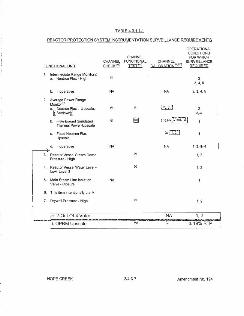
TABLE 4 .3 . 1 . 1 -1
REACTOR PROTECTION SYSTEM INSTRUMENTATION SURVE ILLANCE REQUIREMENTS
FUNCTI ONAL UNIT
1 ' I ntermediate Range Monitors: a. Neutron Flux - H igh
b. Inoperative
2. Average Power Range Monitor(!): a. Neutron Flux - U pscale,..
II] Setdowr{TI b. Flew BiaseG Simulated
Thermal Power-Upscale
c. � Neutron Flux -Upscale
d. Inoperative
3. Reactor Vessel Steam Dome Pressure - High
4. Reactor Vessel Water Level -Low, Level 3
5 . Main Steam Line I solation Valve - Closure
6. This item intentionally blank
7. Drywell Pressure - High
je. 2-0ut-Of-4 Voter
,f. OPRM Upscale
HOPE CREEK
CHANNEL CHECK (ml
(b)
NA
(b)
(g)
NA
NA
CHANNEL FUNCTIONAL
TEST (m)
(I)
[§]
(k}
(k)
(k)
- (e)
3/4 3-7
CHANNEL CALIBRATION (a)(ml
NA
l(n), (o) l
OPERATIONAL CONDITIONS FOR WHI CH
SURVEI LLANCE REQUIRED
2 3, 4 , 5
2, 3, 4, 5
2 -3,-4
(d}wfRl l(g) (n), (on
(dd(n), (ill
NA 1 ' 2,.a.-4 11 2
1 , 2
1 ' 2
NA 1 , 2 (g) ;::;: 1 9% RTP
Amendment No. 1 94

TABLE 4.3. 1 . 1 - 1 (Continued) REACTOR PROTECTION SYSTEM INSTRUMENTATION SURVEILLANCE REQUIREMENTS
CHANNEL OPERATIONAL CHANNEL FUNCTIONAL CHANNEL CONDITIONS FOR WHICH
FUNCTIONAL UNIT CHECK tm) TEST <ml CALl BRA TION tml SURVEILLANCE REQUIRED
8.
9. 1 0.
1 1 .
12.
(a) (b)
(c) (d)
� (e) I (f) r (g)
(h) (i) (j)
. (k) (I)
Scram Discharge Volume Water level - High:
1 , 2, 5°} a. Float Switch NA b. Level Transmitterffrip Unit (k} 1 , 2, 5(j} Turbine Stop Valve - Closure NA 1 Turbine Control Valve Fast Closure Valve Trip System Oil Pressure - Low NA 1 Reactor Mode Switch Shutdown Position NA NA 1 , 2, 3, 4, 5 Manual Scram NA NA 1 , 2, 3, 4, 5
Neutron detectors may be excluded from CHANNEL CALI BRATION.
The l RM and SRM channels shall be determined to overlap for at least 1/2 decades during each startup after entering OPERATIONAL
CON D ITIO N 2 and the I RM and APRM channels shall be determined to overlap for at least 1/2 decades during each controlled shutdown, if not performed within the previous 7 days. DELETED
This calibration shall consist of the adjustment of the APRM channel to conform to the power values calcul ated by a heat balance during OPERATIONAL CONDITION 1 when THERMAL POWER � 24% of RATED THERMAL POWER. Adjust the APRM channel if the absolute difference is greater than 2% of RATED THERMAL POWER.
This calibration shall consist of the adjustment of the APRM flow biased channel to conform to a calibrated flow signal. The LPRMs shall be calibrated in accordance with the SurveHiance Frequency Control Program. Verify measured core flo'N (total core flow) to be greater than or equal to established core flow at the existing recirculation loop flo•..: (APRM % f!O\v}. This calibration shall consist of verifying the 6 * 0.6 second simulated thermal power time constant. I Deleted. I This item intentionaHy blank With any control rod withdrawn. Not applicable to control rods removed per Specification 3.9. 1 0. 1 or 3.9. 1 0.2.
Verify the tripset point of the trip unit in accordance with the Surveil lance Frequency Control Program. Not required to be performed when entering OPERATIONAL CON DITIO N 2 from OPERATIONAL CONDITION 1 until 1 2 hours after entering OPERATI ONAL CONDITION 2.
(m) Frequencies are specified in the Surveillance Frequency Control Program unless otheJWise n oted in the table.
[CaH�rE!!ion ir!(?l ud es the fl()W input function. I [The CHAN N E L F U N CTIONAL TEST includes the recirculation flow input function, excluding the flow transmitters. I
j i nsert 1 1 :>HOPE CREEK 3/4 3-8 Amendment No. 1 87
----· ·- · ·- ·-------·
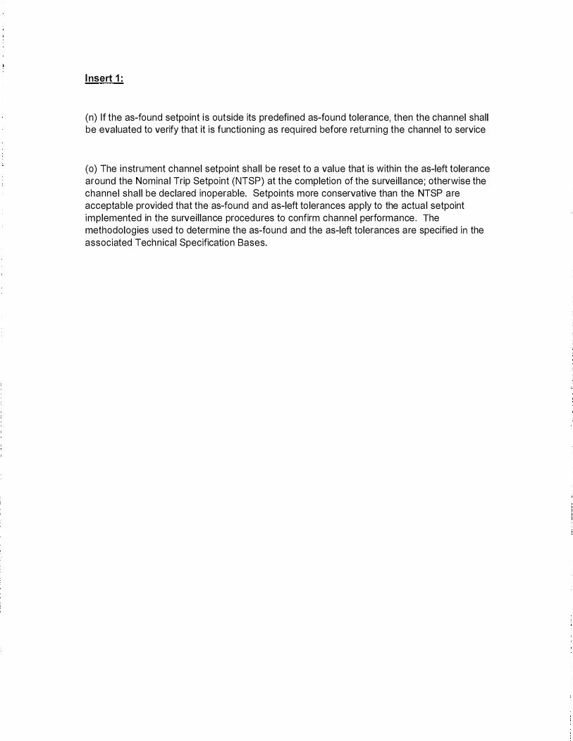
I nsert 1 :
(n) If the as-found setpoint is outside its predefined as-found tolerance, then the channel shall be evaluated to verify that it is function ing as requ i red before return ing the channel to service
(o) The i n strument channel setpoint shall be reset to a value that is with in the as-left tolerance around the Nominal Trip Setpoint (NTSP) at the completion of the survei l lance ; otherwise the channel shal l be declared inoperable. Setpoints more conservative than the NTSP are acceptable provided that the as-found and as-left to lerances apply to the actual setpoint implemented in the surveil lance procedures to confirm channel performance . The methodolog ies used to determine the as-found and the as-left tolerances are specified in the associated Techn ical Specificatio n Bases.

TABLE 3.3 .6-1 CONTROL ROD BLOCK I NSTRUMENTATION
3 . SOURCE RANGE MON ITORS a. Detector not full in(b)
b. Upscale(c)
c. lnoperative(c)
d . Downscale(d)
4. I NTERMEDIATE RANGE MONITORS a. Detector not fu l l in b. Upscale c. I noperative d . Downscale(e)
5. SCRAM DISCHARGE VOLUME a. Water Level-High (Float Switch)
6. �EAG+OR GOOLANT S¥S+EM !Deleted ] R�lJ.bA-T+GN-�W · ···
a-: Upscale &: Inoperative &. Comparator
7. REACTOR MODE SWITCH SHUTDOWN POSITION
HOPE CREEK 3/4 3-57
M I N I MUM O PERABLE CHANNELS APPLICABLE
PER TRI P OPERATI ONAL FUNCTION CONDITIONS ACTION
2 1 * 60 2 1 * 60 2 1 * 60
Simulated Thermal Power - U pscale (Setdown)
4@] 1 61 4@::1 1 1 2 61 4@] 1 61 4@] 2 61
3 2 61 2 5 61 3 2 61 2 5 61 3 2 61 2 5 61 3 2 61 2 5 61 6 2, 5 61 6 2, 5 61 6 2 , 5 61 6 2, 5 61
2 1 , 2 , 5** 62
2 3, 4 63
Amendment No. 1 94

TABLE 3 . 3 . 6· 1 (Conti nued)
CONTRO L ROD BLOCK I NSTRUMENTAT ION
ACTION
ACT I ON 60 Dec l are the RBM i noperabl e and take the ACTION requi red by Spec i fication 3 . 1. 4 . 3 .
ACTION 61 - Wi th the numb er o f OPERABLE Channe l s :
a . One l e s s than req u i red by t h e M i n i mum OPERABLE Channe l s per T r i p Func t i o n requ i rement , restore the i noperabl e chann e l to OPERABLE status wi thi n 7 days o r p l ace the i noperab l e channel i n the tri pped condi t i o n wi th i n the next hour.
b . Two o r more l es s than requ i red by the Mi n i mum OPER.ABLE Channe l s per T r i p Func t i o n requ i rement , p l ac e at l ea s t o n e i noperab l e channel i n t h e t ri pped cond i t i o n wi th i n one hour. · ·
ACTION 62 - W i th the number of OPERABLE channe l s l es s than requi red by the M i n i mum OPERABLE Channel s per T r i p F u nct i on requi remen t , p l ace the i noperab l e chann e l i n the tri pped condi ti on wi t h i n one hour .
ACT ION 63 - W i th the number o f OPERABLE channe l s l es s than requi red by the " .
.,.,.--......,
, I \......./
Mi ni mum OPERABLE Channe l s per Tri p F uncti o n requi reme n t , i n i t i ate · a rod b l ock. ".._/
**
a .
b .
c .
. d � i .
Wi th · more than one control rod w i thdrawn . Not app l i cab l e to control rods removed per Spec i fi cati on 3 . 9 . 10 . 1 or 3. 9 . 10 . 2 . ·
The RBM s hal l be automati c al l y bypassed when a per i pheral control rod i s s e l ected.
Th i s fun c t i o n shal l be automati c a l ly byp a s s ed i f detector count rate i s > 10� cp s ?r the I RM channe l s are on range 3 or h i g�er.
. .
T h i s fun c t i o n s h a l l be automat i c a l l y byp a s s ed when the as soci ated I RM channe l s are o n range 8 or h i gher.
.
· .Thi s funct i on shal l be automat i cal l y bypassed when the I RM channe l s are · ori range 3 or h i gh_e r. :
.
, ' ' ' e . Thi s ', fu n ct i on s hal l be automat i ca l l y bypas sed when t h e I RM ch an nel s are
o n range t:
HOPE CREEK 3/4 3- 58 Amendmen t No , 19 ·
SEP 2 8 \9S6

i) Low Trip Setpoint (LTSP)(b)
ii) I ntermediate Trip Setpoint (ITSP)(c)
iii) High Trip Set.point (HTSP)(d)
**
**
**
TABLE 3 . 3 . 6. - 2
TRIP FUNCTION
CONTROL ROD BLOCK INSTRUMENTATION SETPOINTS
TRIP SETPOINT ' 1 . ROD BLOCK · MONITOR
- � i- . Flow · niaaed :i:-i . High: Flo�; Clamped
b . Inopera·t i ve ·r=:---:---:-.....,,-----,----. c . Downscale �S imulated Thermal Power I
2 . APRM \jt . · a . Flow Biased Neutron F±tix - Upscale b . Inoperative c . Downscal e d . Neutron Flux
3 . SOURCE RANGE MONI TORS a . Detector not ful l b . Ups cale c . Inoperative d . Downscale
�--L;.U.t-"
Simulated Thermal Power - Upscale (Setdown)
4 . INTERMEDIATE RANGE MONITORS a . Detector not fu� l in b . · Upscale
c . , Inoperat ive d. Downscale
5 . SCRAM DISCHARGE VOLUME a . Water Leve l - High +Float Swi tch)
6 . a
7 . REACTOR MODE SWITCH SHUTDOWN POS ITION
� 9-;-6-6 � � :J:.l..G.%-NA
I 65%*
EJ :G 5% ef RA'I'ED 'I'HERUAL POWER
- � s 0 . 5 7 (w-.b.w} + 5-3 % * < 1 NA [§] . � 4 % of RATED THERMAL POWER
. S l l % of RATED THERMAL POWER
with a NA maximum of s l . � x l 0 5 cps � 1 08% of NA RATED � 3 cps THERMAL
NA S l 0 8 / l 2 5 divis ions of
ful l scale
NA � 5 / l 2 5 divis ions o�
ful l scal e
POWER
l 0 9 -' i " {North Volume ) 1 0 8 ' 1 1 . 5 " ( S outh Volume }
� HH of rated Hew-N:A:
NA
**
**
**
ALLOWABLE _VALUE'
� 9-;-6-6 � + 6-&%-*-5 3±9% NA EJ �3 'li o£ R.."'\'I'ED THBRU.""� �
with a maximum of 1 1 1 % of
� RATED
s o . 5 7 (w-b.w) + S G % * < �THERMAL
NA · . POWER
� 3 % of RATED THERMAL POWER S l 3 % of RATED THERMAL POWER
NA s 1 . 6 x 1 0 5 cps NA � 1 . 8 cps
NA S l l 0 / 1 2 5 divis i on� o f
ful l scale NA <': 3 / l 2 5 divis i ons of
·ful l scale
l 0 9 ' 3 " (North Volume ) l 0 9 ' 1 . 5 " ( South Volume )
< 114% of rated flow NA < 11% Flow de�iation NA
,.. The rod bl ock funct ion i s varied a s a funct ion of recircul ation loop f low (w) and b.w which · is def ined as . ' the di f ference in indicated drive f low ( in perc�nt of drive f l ow whi ch produce s rated core f low) ;between
two loop and s ingl e l oop operat ion at the same . core f low · ** Refer to the CORE OPERATING LIMITS REPORT for these values
�OPE CREEK .
3 /4 3 - 5 9 " Amen ment NOj :z!J. 'a. Each upscale trip level is applicable over its specified rated power range. All RBM trips are automatically bypassed below the low power setpoint (LPSP). The u pscale L TSP is applied between the LPSP and the i ntermediate power setpoint (!PSP). The u pscale ITSP is applied between the l PSP and the high
'-----!power setpoint (HPSP). The HTSP is applied above the H PSP. b. APRM Simulated Thermal Power is <': 28% and < 63% RTP c. APRM Simu lated Thermal Power is ;:o: 63% and < 83% RTP d. APRM Simulated Thermal Power is <': 83%
'-

TABLE 4.3.6�1 CONTROL ROD BLOCK INSTRUMENTATION SURVEI LLANCE REQU IREMENTS
CHANN EL CHANNEL FUNCTIONAL
TRIP FUNCTION CHECK(fl TEST(!)
1 .
2.
ROD BLOCK MON ITOR a. Upscale NA
b. I noperative NA
c. Downscale NA
APRM �Simulated Therm�l Power I
a. -Fklw-Blased N eutroA-Fk:tx NA - Upscale
b. Inoperative NA c. Downscale NA d.
(c) (c) (C)
OPERATIONAL CONDITIONS FOR WHICH
CHANN EL SURVEI LLANCE CALIBRATION(a)(fl REQUIRED
l(g), (hll 1 * NA 1 *
1 *
NA 1 ' 2 1 2 NeutreA FlU* IJpseale, NA
�Simulated Thermal Power - Upscale (Setdown) Slaffilfl 3.
4.
5 .
6.
7.
SOURCE RANGE MONITORS a. Detector not full in NA b. Upscale NA c. Inoperative NA d. Downscale NA
INTERMEDIATE RANGE MON ITORS a. Detector n ot fu l l in NA b. Upscale NA c. I noperative NA d. Downscale NA
SCRAM DISCHARGE VOLUME a. Water Level-High (Float NA
Switch)
·REAG-l-GR-GGGI::AN-1 I Deleted J ���±[ii;M REiiGIRG!;;lbA+IGN · -
FbGW a, IJflSCale NA b-. Inoperative NA -&. Gomparater NA REACTOB MODE SWITCH NA SHUTDOWN EO§ITION
HOPE CREEK
NA 2, 5 2, 5
NA 2, 5 2, 5
NA 2, 5 2, 5
NA 2, 5 2, 5
1 , 2, 5**
4 4 4
(e) NA 3, 4
3/4 3-60 Amendment No. 1 94

TABLE 4.3 .6-1 (Continued)
CONTROL ROD BLOCK INSTRUMENTATION SURVEILLANCE REQU IREMENTS
NOTES :
a.
b.
c .
d.
e .
f.
**
Neutron detectors may be excluded from CHANNEL CALI BRATION .
DELETED
I ncludes reactor manual control multiplexing system input.
DELETED
Not requ i red to be performed unti l 1 hour after reactor mode switch is in the shutdown position.
Frequencies are specified in the Surveil lance Frequency Control Program unless otherwise noted in the table.
With THERMAL POWER � 30% of RATED THERMAL POWER. �See TS 3 . 1 .4.3 Applicabi l ity.!
With more than one control rod withdrawn . Not applicable to control rods removed per Specificat ion 3. 9. 1 0 . 1 or 3 . 9 . 1 0. 2.
(g) If the as-found setpoint is outside its predefined as-found tolerance, then the channel shal l be evaluated to verify that it is function ing as requ i red before returning the channel to service.
(h) The instrument channel setpoint shal l be reset to a value that is within the as-left - tolerance around the Nominal Trip Setpoint (NTSP) at the completion of the survei l lance;
otherwise the channel shal l be declared inoperable. Setpoints more conservative than the NTSP are acceptable provided that the as-found and as-left tolerances apply to the actua l setpoint implemented in the survei l lance procedu res to confirm channel performance. The methodologies used to determine the as-found and the as-left tolerances are specified in the associated Techn ical Specification Bases.
HOPE CREEK Amend ment No. 1 87

3/4 .3 I NSTRUMENTATION
3/4. 3. 1 1 OSGILLATION POWER RANGE MONI+OR jDeleted
LIMITING GONDI+ION FOR OPERA+ION
�-F.fH:l·r--efla·R-ABls-B-f-tf::l.e-GP.R-M-ifls.tFtlffieffiat�oA-SA-aJ.I-I:J.e-GP€-RA.fl.b.E2:.,-Ei::lef\-G-PHM oh ann el-pefied 9a&e4-al§Gfitflffi-affi].91it�:JEle trip seti*J�than or �-e--#re-�1� &J3eo-itieEJ-i.n-the-GG-RE--GP.§.RAl:f.NG-bi-MI+&-R-E-P.GR+.
/\PPLICABILIT¥: OPERATIONAL CONDITION 1 , when THERMAL POVVER is greater than or equal to 24% of RATED THERMAL POVVER.
ACTIONS
a: With one or more roquiree channels inoperable:
:1-, Place the inoperable channels in trip within 30 days, or � P+aoe associatee RPS trip system in trip within 30 days, or � 1-Ritiate an alternate method to detect and suppress thermal hydraulie instability
oseillatiens within 3G €lays.
&. With OPRM trip capability net maintainee:
:1-, ifl.itiate-aHemate--ffie#re€l-te-Ge�press the�tJ+ie-i.n.stabHity ossi.flatiBfl-5-With.in 12 hours, aA€i
� Restore OPRM trip capability within 120 days.
e: Other.vise, reduce THERMAL POVI/ER te less than 24% RTP ·.vithin 4 hours.
SURVEILL.A,NCE REQUIREMEN+S
4.3. 1 1 . 1 Perform CHANNEL FUNCTIONAL TEST in acoerdanee with the Sur.·eillance Froquenoy Control Program.
4-:-3-,---1-4-:-...'LGa+ibFate the loeal-p�en+tef-tA-aBOOrdance with th-8-SUFVciltance FreEJUensy--Ce-n-tfe-1 Program in acoordance \Vith Note f, Table 4.3.1 . 1 1 efTS 3/4.3.1.
4.3. 1 1 .3 Perform CHANNEL CALIBRATION in aocordance '.Vith the Surveillance Frequency Control �·eu-troo--deteet8fS-8re excluded,
4.3. 1 1 A Perform LOGIC S¥STEM FUNCTIONAL TEST in accord a nee with the Surveillance Frequeney Control Program.
4-:-3-44..,...5---Vefffy--OPR-M-1-s-ab+eEI-when--Tt-+E---RMAb--P-OWE-R-i.s � 2-&.1-%-R+P--an-d-reeifC-I::lfa.t�sA-dfive-flew ;;; the value corresponding to tho percentage of rated core flow as specified in the CORE OPERATING ldMI-"FS--R-ep.QH:r-i·n--aeoor��·th-tfl.e-S.u.fve#lanGe-Frequ.eney--Gen-tro-1-P-re§fam, The vai{:!€--Gpeo-i#od-ifl tho CORE OPERATING LIMITS REPORT shall not be less than 60% of rated eoro flew.
4.3. 1 1 .6 Verify the RPS RESPONSE TIME is within limits in aeoordanco with the Surveiiianeo Frequency Control Program. Neutron detesters are exciU€J.e€1,
:!: 'A'hen a channel is placed in an inoperable status solely for performance of required Sur.'eillances, entry into associated ACTIONS may-be delayed for up to 6 hours, provided the 0-P-RM maintains trip capability.
HOPE CREEK 3/4 3· 1 1 0 Amendment No. 1 90

3 / 4 . 4 REACTOR COOLANT SYSTEM
3 /4 . 4 . 1 RECIRCULATI ON SYSTEM
RECIRCULATION LOOPS
L I M I T ING COND I T I ON FOR O PERATI ON
3 . 4 . 1 . 1 Two reactor coolant sys t em recirculat ion l oops sha l l be in ope ra t ion . ·
AP P L I CAB I LITY : OPERAT I ONAL CONDI T I ONS 1 * and 2 .* .
ACTION :
a . W i t h one reactor · cool ant sys t em reci rcul at i on l oop not· in operat ion :
1 . Within 4 hours :
a )
b ) c )
d)
e )
f )
g )
P l ace th� rec ircul a t i pn f l ow tont rol system i n the Loc al Manual mode , and
Reduce THERMAL POWER to � 6 0 . 8 6 % o f RATED THERMAL POWER , and I ncrease the MINIMUM CRITI CAL POWER. RAT I O (MCPR) Safety Limit ' p e r Spe c i f icat i o� 2 . 1 . 2 , and Reduce t he AVERAGE PLANAR LINEAR HEAT GENERATION RATE ( APLHGR ) l imit to a· value spe c i f i ed in the CORE O PERAT ING LIMITS REPORT
·.for s ingle loop operat i o n , and Reduce the L INEAR HEAT GENERATION RATE ( LHGR) l imit to a value '· s p e c i f i e d in the CORE OPERATING L I MITS REPORT for s ingl e loop opera t ion , and L i m i t the speed of the ·operating r e c i rcul a t i on pump to less . ) than· or e qual t o 9 0 % of rated pump speed, . and . Per form surve i l l ance requi rement 4 . 4 . 1 . 1 . 2 i f THERMAL ,POWER i s � 3 8 % o f RATED THERMAL POWER or the r e c i rcul ation loop f l ow i n t h e operat ing l o op i s $ 5 0 % of r a t e d l oop flow .
2 . Within 4 hour s , reduc e the Average Power Range Manito� (APRM ) Scram Trip S e tpo int s and Al l owab l e 'Values to th o s e appl icab l e for s ingl e re c i r cu l at i on loop ope r a t i on per Spe c i f i ca t i on 2 . 2 . 1 ; e��, w-±-t::h--t-he -'I'ri-p---Se1::p� · a-nd Allowable Values ' th---one ttip system not reduced t:o thmre o:ppl-±-ccrl;J1:-e f·cn: shrgl-e re-chcalat±on h::rop opexation, · piace the affected trip �,),...,�� tripped concl-i-t-±efl-aoo within the following 6 ' hou-r-s-, redtl-ce Setpoints and Al']:owable Values of the affecLBd channels t·o--'<-'h--� appl±cabre fur s-:i:rrg-1-e xe•� hcalatiou ldop qpexation p-er ·
Specification 2--;-2-;+.
3 . W i thin 4 hour s , reduce the APRM Control Rod B l ock Tr ip Setpo ints and . Al l owab l e Values to tho s e appl icab l e for · s ingl e reci rcul ation l oop operat ion per Spec i f i ca t i on 3 . 3 . 6 · othexwise , with the T!±p Setpoint and Allowable Values ' IT'-orre trip funct-i-on not
* S e e S p e c i a l Te s t Except ion 3 . 10 . 4 .
HOPE CREE K 3 /4 4 - 1 ot herwise decla re the APRM channel I N OPERABLE
· and take the action of Control Rod B lock
I nstru mentation TS 3.3 .6 ACTI O N a and b.
Amendment No . 1 7 4 otherwise declare the APRM channe l
I N O P E RABLE a nd take the action of R PS 1---� I nstru mentation TS 3 .3 .1 ACTION a .

REACTOR COOLANT S Y ST EM
ACT ION ( Cont i nu e d )
I e du ee d t o-t-!Te-s-e-a:-]9p-±-:i:-ea-hle---:§or single r e c�atie� operation , place at least one affected channel in the tripped condition and within the following 6 hours , reduce the �rip Sctpoints and Allowable Values of the affected channels to those applicable for single recirculation loop operation per Specification 3 . 3 . 6 .
� Within 4 houro1 reduce the Rod Bloc� Monitor Trip Setpoints and '-ID::--e"""le-tc-e-d-:-�1 Allov.·able Values to those applical3le for s:i:ngle recirculation · loop operation per Specification 3 . 3 . 6; othends e , vdth the Trip
Setpoints and Allowable Values associated with one trip function not reduced to those epplicable for single recirculation � operation , place at leest one affected channel in the tripped condition and >vi thin the follmdng 6 hours 1 reduce the Trif' octpointo and Allowable Values of the remaining channels to those applicable for single recirculation loop operation per &p-eei-f-:i:-eu-t-:i-ert---3-:-3-.-6-.
5 . D e l e t e d
6 . O t h e rwi s e be i n a t l e a s t HOT S H U T DOWN w i t h i n t h e next 1 2 hour s .
b . Wi t h n o r e a c t o r coolant s ys t em r e c i r cu l a t i on l oops i n ope r a t i on ,
i n i t i a t e me a s ur e s t o pl ace t h e u n i t i n a t l e a s t START U P w i t h i n 6 hours and i n HOT S H UTDOWN w i t h i n the next 6 hours .
HOPE CREEK 3 / 4 4 - 2 Amendment No . 1 8 0

2.2 Reactor Protection System I nstrumentation Setpoints ADMINISTRATIVE CONTROLS 3/4 . 1 .4 .3 Rod Block Monitor
6 . 9 . 1 . 8 Deleted
CORE OPERATING LIMITS 3/4.3 . 1 Reactor Protection System Instrumentation 3/4 .3 .6 Control Rod B lock Instrumentation
6 . 9 . 1 . 9 Core operatin sha l l be establi shed and documented in the PSEG Nuc lear LLC ge ated CORE OPERATING LIMITS REPORT before each reload
3 / 4 . 2 . 1
3 / 4 . . 2 . 3
3 / 4 . 2 . 4
3/4 . 3 . 11
ning part of a reload cycle for the following Technical
AVERAGE PLANAR LINEAR HEAT GENERATION RATE
MINIMUM CRITICAL POWER RATIO
LINEAR HEAT GENERATION RATE OSCILLATION POWER R.\NGE MONITOR (OPRM)
The analytical methods used to determine the core operating l imits sha l l be those previously reviewed and approved by NRC as app l icable in the following document s :
1 . NEDE- 2 4 0 1 1 - P-A, " General Electric Standard Appl ication for Reactor Fuel ( GESTAR - II ) "
2-.- GENPD-3 97 P-A-. !!....!-mff)-:::cov:eQ-F-l-ew-Mea..su�emen-t---Asmsy:-Y.s:i-�1ew U.l-t-r-aso.ni..Q---F-1ew-Mea-�me��
·
� NEDO 32465-A, Reastor Stability Detect and Suppress Solutions Li..eens-iRg-Ba-s-.i,s-Me-�logy f-er-Reload Applications, AUgust �
The CORE OPERATING LIMITS REPORT will contain the complete identi fication for each of the TS referenced topical reports used to prepare the CORE OPERATING LIMITS REPORT ( i . e . , report number t i t le , revi s ion , dat e , and any supplements ) .
The core operating l imit s sha l l be determined so that a l l appl icable l imits ( e . g . , fuel thermal -mechanical limits , core thermal-hydraulic limits , ECCS
l imi ts , nuclear l imi t s such as shutdown margin , and transient and accident analys is limits ) of the s afety analys is are met .
The CORE OPERATING LIMITS REPORT , including any mid-cycl e revi s ions or supplements there t o , sha l l b e provided upon i ssuanc e , for each reload cyc l e , to the NRC Document Control Desk wi th copies to the Regional Administrator and Re s i dent Inspector .
HOPE CREEK 6 - 2 0 Amendment No . 161
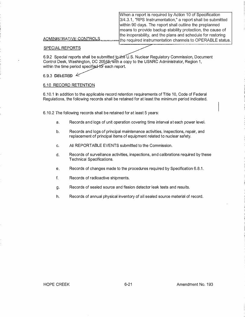
When a report is required by Action 1 0 of Specification 3/4 . 3 . 1 , "RPS I nstrumentation," a report shal l be submitted with in 90 days . The report shal l outl ine the preplanned means to provide backup stabi l ity protection, the cause of the inoperabi l ity, and the plans and schedule for restoring
!:!A�D�M!,!,!IN:!!I�S�I�R�Ab!:T�IV!:!!E=C�O�N�L�RQ�L�S'=====lthe requ i red instrumentation channels to OPERABLE status .
SPEC IAL REPORTS
6.9.2 Special reports shall be subm itted t U .S. N uclear Regu latory Commission, Document Control Desk, Washington, DC 205 , ith a copy to the USNRC Administrator, Region 1 , within the time period specifi r each report.
6.9.3 DELETED
6. 1 0 RECORD RETENTIO N
6 . 1 0 . 1 In addition to the appl icable record retention requirements of Title 1 0, Code of Federal Reg ulations, the following records shal l be retained for at l east the m inimum period Ind icated .
6. 1 0.2 The fol lowing records shall be retained for at least 5 years:
a . Records a n d logs of unit operation covering time interval a t each power leve l .
b. Records and logs of principal maintenance activities, inspections, repair, and replacement of principal items of equipment related to nuclear safety.
c. All REPORTABLE EVENTS submitted to the Commission .
d . Records of surveil lance activities, inspections, a n d calibrations required by these Technical Specifications.
e . Records of changes made to the procedures required by Specification 6.8.1 .
f. Records of radioactive shipments.
g . Records of sea led source and fission detector leak tests and resu lts . h . Records of annual physical inventory of a l l sealed source material of record .
HOPE CREEK 6-2 1 Amendment No. 1 93

Attachment 3 LAR H15-01 LR-N15-0178
Mark-up of Proposed Technical Specification Bases Pages

2.2 LIMITING SAFBTY SYSTEM SETTINGS
BASES
2. 2,1 REACTOR PROTECTION SYSTEM lNSTROMENTA'l'!ON SETl?OINTS
The Reactor Protection System instrumentation setpoints specified in Table 2.2.1-1 are the values at which the reactor trips are set for each parameter. The Trip Setpoints have been selected to ensure that the reactor core and reactor coolant system are prevented from exce eding their Safety Limits during normal operation and design basis anticipated operational occurrences and to as sist in mitigating the consequences of accidents. Operation wi th a trip set less conservative than its Trip Setpoint but within its specified Allowable Value is acceptable on the basis that the difference
between each T rip Setpo:l.nt and the Allowable Va).ue is an allowance for instrument drift specifically allocated for each trip in the safety analyses,
1. Intermediate Range Monitor, Neutron Flux - High
The IRM system consists of 8 chambers, 4 in each of the reactor trip systems. The lRM is a 5 decade 10 range instrument. The trip setpoint of 120 divi s ions of scale is active in each of the 10 ranges. 'I'hus as the IRM is ranged up to accommodate the increase in power level, the trip setpoint is also ranged up. The IRM instruments provide for overlap with both the APRM and SRM systems.
·
The most significant source of reactivity changes during the power increase is due to control rod withdrawal. In order to ensure that the IRM provides the required protection, a range of rod withdrawal accidents have been analyzed. The results of these analyses are in Section 15.4 of the FSAR. The most .severe case involves an initial condition in which THERMAL POWER is at approximately 1% of RATED THERMAL POWER . Additional conservatism was taken in this analysis by assuming the IRM channel closest to the control rod being withdrawn is bypassed. The results of this analysis show that the reactor is shutdown and peak power is limited to 21% of RA'l'ED THERMAL POWER with the peak fuel enthalpy well below the fuel failure threshold of 170 cal/gro. Based on this analysis, the IRM provides protection against local control rod errors and continuous withdrawal of control rods in sequence and provides backup protection for the APRM.
2. Average �ower R�nge Monitor
�n at low pressure and low flow during STARTUP1 the �PRM scram setting of �% of RATED THERMAL POWER provides adequate thermal margin between the setpoint and the Safety Limits. The margin accommodates the anticipated mane uve rs associated with power plant startup. Effects of increasing pressure at zero or low void content are minor and cold water from sources available during startup is not much colder than that already in the system. Temperature coefficients are small and control rod patterns are constrained by the RWM. Of all the possible sources of reactivity input, uniform control rod withdrawal is the most probable cause of significant power increase.
HOPE CREEK Amendment No. 174 (PSEG Issued)
I �/
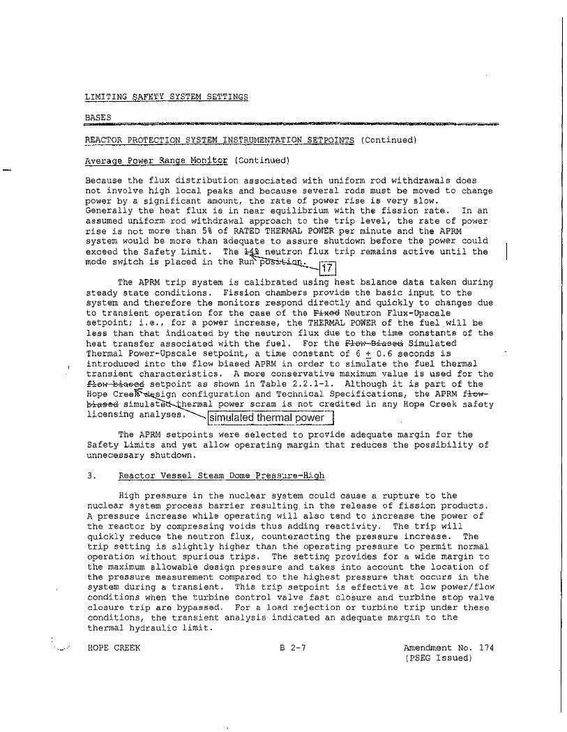
LIMITING SAFETY SYSTEM SETTINGS
BASES
REACTOR PROTECTION SYSTEM INSTRUMENTATION SETPOINTS (Continued)
Average Power Range Manito£ (Continued)
Because the flux distribution associated with uniform rod withdrawals does not involve high local peaks and because several rods must be moved to change power by a s;Lgnificant amount, the rate of power rise is very slow. Generally thCil heat flux is in near equilibrium with the fission rate. In an assumed uniform rod withdrawal approach to the trip level, the rate of power rise is not more than 5% of RATED THERMAL POWER per minute and the APRM system would be more than adequate to assure shutdown before the power could
exceed the Safety Limit. The neutron flux trip �emaina aotive until the mode switch is placed in the Run po ·. ·
The APRM trip system is calibrated using heat balance data tak.en during steady state conditions. Fission chambers provide the basic input to the system and therefore the monitors respond directly and quickly to changes due to transient operation for the case of the � Neutron Flu�-Upscale setpoint; i.e., for a power increase, the THmRMAL POWER of the fuel will be less than that indicated by the neutron flux due to the time constants of the heat tr.a.nsfer associated with the fuel. For the Flo11 Biaae-cl Simulated 'l'hermal Power-Upscale setpoint, a time constant of 6 :t 0. 6 .eeoonds is introduced into the flow biased APRM in order to simulate the fuel thermal. transient characteristics. A more conservative maximum value is used for the
flow biased setpoint as shown in Table 2.2.1-1. Although it is part of the Hope Cree sign configuration and Technical Specifications, the APRM £�� biased simulate hermal power scram is not credited in any Hope Creek safety licensing analyses· !simulated thermal power I
The ArRM setpoints were selected to provide adequate margin for the Safety Limits and yet allow operating margin that reduces the possibility of unnecessary shutdown.
3. Reactor Vessel Steam Dome Pressure-High
High pressure in the nuclear system could cause a rupture to the nuclear system process barrier resulting in the releas e of fission products. A pressure increase while operating will also tend to increase the power of the reactor by compressing voids thus adding reactivity. The trip will quickly reduce the neutron flux, counteracting the pressure increase. The trip setting is slightly higher than the operating pressu.r-e to permit normal operation without spuri ous trips. The setting provides for a wide margin to the ma�imum allowable design p ress ure and takes into account the location of the pressure measurement compared to the highest pressure that occurs in the system du ring a transient. This trip setpoint is effective at low power/flow conditions when the turbine control valve fast closure and turbine stop valve closure trip are bypaso;ed. For a load rejection or turbine trip under thc;Jse conditions, the transient analysis indicated an adequate margin to the thermal hydraulic limit.
HOPE CREEK 8 2-7 Amendment No. 174 (PSEG Issued)

3/4.3 INSTRUMENTATION
BASES
3/4 .3.1 REACTOR PROTECTION SYSTEM INSTRUMENTATION
The reactor protection system automatically initiates a reactor scram to:
a. Preserve the integrity of the fuel cladding.
b. Preserve the integrity of the reactor coolant system.
c. Minimize the energy which must be adsorbed following a loss-of-coolant accident, and
d. Prevent inadvertent criticality.
This specification provides the limiting conditions for operation necessary to preserve the ability of the system to perform its intended function even during periods when instrument channels may be out of service because of maintenance. When necessary, one channel may be made inoperable for brief intervals to conduct required surveillance. r::[ R:- e-=- fe-re_ n_c _e"""1 -(
,---,
The reactor protection system is made up of two independent trip systems. There are usu y four channels to monitor each parameter with two channels in each trip system. The outputs of the c an nels in a trip system are combined in a logic so that either channel will trip that trip system. The tri ing of both trip systems will produce a reactor scram. The system meets the intent of IEEE-279 fo nuclear power plant protection systems. The Surveillance Frequency is based on operating exper.· nee, equipment reliability, and plant risk and is controlled under the Surveillance Frequency ontrol Program. Surveillance and maintenance outage times have been determined in accordance with NEDC-30851 P, "Technical Specification Improvement Analyses for BWR Reactor Protection System," as approved by the NRC and documented in the SER (letter to T. A. Pickens from A. Thadani dated July 1 5, 1 987 The bases for the trip settings of the RPS are discussed in the bases for Specification 2.2 . 1 .
The measurement o f response time i n accordance with the Surveillance Frequency Con Program provides assurance that the protective functions associated with each channel are com within the time limit assumed in the safety analyses. No credit was taken for those channels with response times indicated as not applicable. Response time may be demonstrated by any series of sequential, overlapping or total channel test measurement, provided such tests demonstrate the tot channel response time as defined. Sensor response time verification may be demonstrated by eithe (1 ) inplace, onsite or offsite test measurements, or (2) utilizing replacement sensors with certified respon e times. Selected sensor response time testing requirements were eliminated based upon NEDO- 3229 , "Sys Analyses for Elimination of Selected Response Time Testing Requirements," as approved by t e NR and documented in the SER (letter to R.A. Pinelli from Bruce A. Boger, dated December 28, 1 994). Th Reactor Protection System Response Times are located in UFSAR Table 7.2-3.
As noted, the SR for the APRM Neutron Flux - Upscale, Setdown channel functional test is not equired to be performed when entering OPERATIONAL CONDITION 2 from OPERATIONAL
CONDITION 1 , since testing of the OPERATIONAL CONDITION 2 required APRM Function cannot be performed in OPERATIONAL CONDITION 1 without utilizing jumpers, lifted leads, or movable links. This allows entry into OPERATIONAL CONDITION 2 if the frequency is not met per SR 4.0.2. In this event, the SR must be performed within 12 hours after entering OPERATIONAL CONDITION 2 from OPERATIONAL CONDITION 1 . Twelve hours is based on operating experience and in consideration of providing a reasonable time in which to complete the SR.
� The response time testing is performed from the 2-out-of 4 Voter logic module output relays through the RPS contacts. The response time of the APRM and 2-out-of-4 Voter electronics from the LPRM detector inputs to the "coil" in the Voter is e ntirely determined by the digital processing. The time required for the digital processing remains constant within statistical variations. The time base in the digital equipment is confirmed as part of the channel calibration . In addition, automatic self-test functions compare the independent APRM clocks and will detect any significant changes in frequency.
) and NEDC-3241 0P-A, "Nuclear Measurement Analysis and Control Power Range Neutron Monitor
(NUMAC PRNM) Retrofit Plus Option Ill Stability Trip Function."
Amendment No. 1 87 (PSEG Issued)

BASES INSERT 1
Function 2. Average Power Range Monitor
The APRM channels provide the primary indication of neutron flux with in the core and respond almost instantaneously to neutron flux increases. The APRM channels receive input signals from the Local Power Range Monitors (LPRMs) with in the reactor core to provide an indication of the power distribution and local power changes. The APRM channels average these LPRM signals to provide a continuous indication of average reactor power from a few percent to greater than RTP. Each APRM also includes an Oscillation Power Range Monitor (OPRM) Upscale Function which monitors small groups of LPRM signals to detect thermal�hydraulic instabilities. The system conforms to the requ irements of IEEE�603.
The APRM System is divided into four APRM channels and four 2�0ut�Of�4 voter channels. Each APRM channel provides inputs to each of the four voter channels. The four voter channels are d ivided into two groups of two each, with each group of two providing inputs to one RPS trip system. The system is designed to allow one APRM channel, but no voter channels, to be bypassed. A trip from any one unbypassed APRM will result in a "half�trip" i n all four of the voter channels, but no trip inputs to either RPS trip system.
APRM trip Functions are voted independently in three groups:
Functions 2.a, 2.b, 2.c, and 2.d are voted in one group, OPRM Upscale Function 2.f and 2.d in a second group, and the OPRM Defense I n Depth Algorithm (DIDA) and 2.d functions in the third group. Therefore, any Function 2.a, 2. b, 2.c, OR 2.d trip from any two unbypassed APRM channels will result in a full. trip in each of the four voter channels, which in turn results in two trip inputs i nto each RPS trip system logic channel {A1 , A2, B1, and 82). S imilarly, any Function 2.f OR 2.d trip from any two unbypassed APRM channels will result in a full trip from each of the four voter channels. Similarly any DIDA OR Function 2.d trip from any two unbypassed APRM channels will result in a full trip from each of the four voter channels.
Three of the four APRM channels and all four of the voter channels are required to be OPERABLE to ensure that no single failure will preclude a scram on a valid signal. In addition, to provide adequate coverage of the entire core, consistent with the design bases for the APRM Functions 2.a, 2.b, and 2.c, at least 20 LPRM inputs, with at least three LPRM inputs from each of the four axial levels at which the LPRMs are located, must be operable for each APRM channel. For the OPRM Upscale, Function 2.f, LPRMs are assigned to "cells" of 3 or 4 detectors. A minimum of 2 LPRMs are requ ired for a cell to be considered responsive. A min imum of 8 responsive cells are required for an OPRM channel to be considered operable.
2.a. APRM Neutron Flux�Upscale (Setdown)
For operation at low power (i.e., OPCON 2), the APRM Neutron Flux-Upscale (Setdown) Function is capable of generating a trip signal that prevents fuel damage resulting from abnormal operating transients in this power range. For most operation at low power levels, the APRM Neutron Flux�Upscale (Setdown) Function will provide a secondary scram to the I ntermediate Range Monitor Neutron Flux-Upscale Function because of the relative setpoints. With the IRMs at Range 9 or 10, it is possible that the Average Power Range Monitor Neutron
1 of 5

Flux-Upscale (Setdown) Function will provide the primary trip signal for a core-wide increase in power.
No specific safety analyses take direct credit for the APRM Neutron Flux-Upscale (Setdown) Function. However, this Function indirectly ensures that before the reactor mode switch is placed in the run position , reactor power does not exceed 24% RTP (SL 2.1.1) when operating at low reactor pressure and low core flow.
Therefore, it indirectly prevents fuel damage during significant reactivity increases with THERMAL POWER < 24% RTP.
The Allowable Value is based on preventing significant increases in power when THERMAL POWER is< 24% RTP.
The Average Power Range Monitor Neutron Flux-Upscale (Setdown) Function must be OPERABLE during OPCON 2 when control rods may be withdrawn since the potential for criticality exists.
I n OPCON 1 , the APRM Neutron Flux-Upscale Function provides protection against reactivity transients and the RWM and rod block monitor protect against control rod withdrawal error events.
2.b. APRM Simulated Thermal Power-Upscale
The APRM Simulated Thermal Power (STP)-Upscale function monitors neutron flux to approximate the THERMAL POWER being transferred to the reactor coolant. The APRM neutron flux is electronically filtered with a time constant representative of the fuel heat transfer dynamics to generate a signal proportional to the THERMAL POWER in the reactor. The trip level is varied as a function of recirculation drive flow (i.e., at lower core flows, the setpoint is reduced proportional to the reduction in power experienced as core flow is reduced with a fixed control rod pattern) but is clamped at an upper limit that is always lower than the APRM Neutron Flux-Upscale Function Allowable Value.
The APRM STP-Upscale function responds to operational events where THERMAL POWER increases slowly. During these events, the THERMAL POWER increase does not significantly lag the neutron flux response and, because of a lower trip setpoint, will initiate a scram before the Upscale neutron flux scram. For rapid neutron flux increase events, the THERMAL POWER lags the neutron flux and the APRM Fixed Neutron Flux-Upscale Function will provide a scram signal before the APRM STP-Upscale function setpoint is exceeded.
Each APRM channel uses one total drive flow signal representative of total core flow. The total drive flow signal is generated by the flow processing logic, part of the APRM channel, by summing the flow calculated from two flow transmitter signal inputs, one from each of the two recirculation loops. The flow processing logic OPERABILITY is part of the APRM channel OPERABI LITY requirements for this function.
2.c. Average Power Range Monitor Neutron Flux-Upscale
The APRM Neutron Flux-Upscale Function is capable of generating a trip signal to prevent fuel damage or excessive RCS pressure.
2 of 5

2.d. Average Power Range Monitor-lnop
For any APRM channel, any time its mode switch is in any position other than "Operate, " an APRM module is unplugged , or the automatic self-test system detects a critical fault with the APRM channel, an lnop trip is sent to all four voter channels. If an APRM channel is inoperable, the voting treats it as though a trip condition exists in that channel.
2.e. 2-0ut-Of-4 Voter
The 2-0ut-Of-4 Voter function provides the interface between the APRM Functions, including the OPRM Upscale Function, and the final RPS trip system logic. As such , it is required to be OPERABLE in the OPERATIONAL CONDITIONS where the APRM Functions are required and is necessary to support the safety analysis applicable to each of those Functions. Therefore, the 2-0ut-Of-4 Voter Function needs to be OPERABLE in OPCONS 1 and 2.
All four voter channels are required to be OPERABLE. Each voter channel includes selfd iagnostic functions. If any voter channel detects a critical fault in its own processing, a trip is issued from that voter channel to the associated trip system.
APRM trip Functions are voted independently in three groups, Functions 2.a , 2.b, 2.c, and 2.d are voted in one group, OPRM Upscale Function 2.f and 2.d in a second group, and the OPRM Defense In Depth Algorithm (DIDA) and 2.d functions in the third group. The voter also includes separate outputs to RPS for the two independently voted sets of Functions, each of which is redundant (six total outputs). The voter Function 2.e must be declared inoperable if any of its functionality is inoperable.
2.f. Oscillation Power Range Monitor (OPRM) Upscale
The OPRM Upscale Function provides protection from exceeding the fuel Safety Limit (SL) MCPR due to anticipated thermal-hydraulic power oscillations.
Reference 3 describes the Detect and Suppress Solution -Confirmation Density (DSS-CD) longterm stability solution and the licensing basis Confirmation Density Algorithm (CDA). Reference 3 also describes the DSS-CD Armed Region and the three additional algorithms for detecting thermal-hydraulic instability related neutron flux oscillations: the Period Based Detection Algorithm (PBDA) , the Amplitude Based Algorithm (ABA) , and the Growth Rate Algorithm (GRA). All four algorithms are implemented in the OPRM Upscale Function, but the safety analysis only takes credit for the CDA. The remaining three algorithms provide defense in depth and additional protection against unanticipated oscillations. OPRM Upscale Function OPERABILITY is based only on the CDA.
The OPRM Upscale Function receives input signals from the local power range monitors (LPRMs) within the reactor core, which are combined into cells for evaluation by the OPRM algorithms.
DSS-CD OPERABILITY requires at least 8 r�sponsive OPRM cells per channel. The DSS-CD software includes a self-test for the responsive OPRM cells; therefore, no SR is necessary.
The OPRM Upscale Function is required to be OPERABLE when the plant is �1 9% RTP, which is established as a power level that is greater than or equal to 5% below the lower boundary of the Armed Region. This requ irement is designed to encompass the region of power-flow operation where anticipated events could lead to thermal-hydraulic instability and related
3 of 5

neutron flux oscillations. The OPRM Upscale Function is automatically trip-enabled when THERMAL POWER, as ind icated by the APRM Simulated Thermal Power, is greater than or equal to 24% RTP corresponding to the MCPR monitoring threshold and reactor recirculation drive flow is less than 70% of rated recirculation drive flow. This reg ion is the OPRM Armed Region. Note (m) allows for entry into the OPRM Armed Region without automatic arming of DSS-CD prior to completely passing through the OPRM Armed Region during both the first startup and the first controlled shutdown following DSS-CD implementation. However, during these periods, the OPRM Upscale Function is OPERABLE and DSS-CD operability and capability to automatically arm shall be maintained at recirculation drive flow rates above the OPRM Armed Region flow boundary.
An O PRM Upscale trip is issued from an OPRM channel when the CDA in that channel detects oscillatory changes in the neutron flux, indicated by period confirmations and amplitude exceeding specified setpoints for a specified number of OPRM cells in the channel. An OPRM Upscale trip is also issued from the channel if any of the defense-in-depth algorithms (PBDA, ABA, GRA) exceeds its trip cond ition for one or more cells in that channel.
Three of the four channels are requ ired to be operable. Each channel is capable of detecting thermal-hydraulic instabilities, by detecting the related neutron flux oscillations, and issuing a trip signal before the SL MCPR is exceeded.
The O PRM Upscale Function is not LSSS SL-related (Reference 3) and Reference 4 confirms that the O PRM Upscale Function settings based on DSS-CD also do not have traditional instrumentation setpoints determined under an instrument setpoint methodology.
TS 3.3.1 Actions
a and b
For APRM functions 2.a, 2.b , 2. c, 2.d, and 2.f, ACTION a. is the only applicable action (ACTION b. is noted as not applicable per Note ** ). For these functions the four APRM channels produce trips that are voted in both trip systems, with two votes being required to in itiate the trip. Three OPERABLE channels are required to meet single failure criteria. If one required APRM channel is INOPERABLE, single failure criteria is not met in both trip systems, therefore placing one trip system in tri p does not restore single failure criteria for the function. However, placing the affected APRM channel in trip does restore single failure criteria for the function in both trip systems by inserting one vote for the affected functions in all voters, requiring only a single additional vote to in itiate a scram in both trip systems. Therefore, for these functions, Note *** specifies that the channel (not the trip system) be placed in a tripped condition.
If two requ i red APRM channels are I NOPERABLE, ACTION a. requ i res placing both channels in trip, which would in itiate the protective action. The provisions of Note* apply and only one channel must be placed in a tripped cond ition. The second channel must be restored to O PERABLE status with in 6 hours or the ACTION required by Table 3.3.1 -1 for the affected trip functions shall be taken.
For APRM function 2.e, TS 3 .3 . 1 ACTION a. and b. apply as they would for any other RPS channel.
4 of 5

TSTF-493
For Functions 2.a , 2.b and 2.c, the CHANNEL CALIBRATION surveillance requirement is modified by two Notes. The first Note requires evaluation of channel performance for the condition where the as-found setting for the channel setpoint is outside its as-found tolerance but conservative with respect to the Allowable Value. Evaluation of channel performance will verify that the channel will continue to behave in accordance with safety analysis assumptions and the channel performance assumptions in the setpoint methodology. The purpose of the assessment is to ensure confidence in the channel performance prior to returning the channel to service. For channels determined to be OPERABLE but degraded , after returning the channel to service the performance of these channels will be evaluated under the plant Corrective Action Program. Entry into the Corrective Action Program will ensure required review and documentation of the condition. The second Note requires that the as-left setting for the channel be within the as-left tolerance of the Trip Setpoint. The as-left and as-found tolerances, as applicable, will be applied to the surveillance procedure setpoint. This will ensure that sufficient margin to the Safety Limit and/or Analytical Limit is maintained. If the as-left channel setting cannot be returned to a setting within the as-left tolerance of the Trip Setpoint, then the channel shall be declared inoperable. The as-left tolerance for this function is calculated using the square-root-sum-of-squares of the reference accuracy and the measurement and test equipment error (including readability). The as-found tolerance for this function is calculated using the square-root-sum-of-squares of the reference accuracy, instrument drift, and the measurement and test equipment error (including readability).
References
1 . NEDC-30851 P-A, Technical Specification Improvement Analyses for BWR Reactor Protection System , " March 1 988.
2. HCGS UFSAR
3. NEDC-33075P-A, Revision 8, "GE Hitachi Boiling Water Reactor Detect and Suppress Solution-Confirmation Density , " November 201 3.
4. J. Harrison (GEH) letter to N RC, "NEDC-33075P-A, Detect and Suppress SolutionConfirmation Density (DSS-CD) Analytical Limit (TAC No. MD0277) , " October 29, 2008 (ADAMS Accession No. ML083040052).
5. NEDC-3241 OP-A, Supplement 1 , "Nuclear Measurement Analysis and Control Power Range Neutron Monitor (NUMAC PRNM) Retrofit Plus Option I ll Stability Trip Function, " November 1 997.
6. NEDC-3241 OP-A, "Nuclear Measurement Analysis and Control Power Range Neutron Monitor (NUMAC PRNM) Retrofit Plus Option Ill Stability Trip Function, " October 1 995.
5 of 5

INSTRUMENTATION
BASES
3/4.3 . 5 REACTOR CORE ISOLATION COOLING SYSTEM ACTUATION INSTRUMENTATION
The reactor core isolation cooling system actuation instrumentation is provided to initiate actions to assure adequate core cooling in the event of reactor isolation from its primary heat sink and the loss of feedwater flow to the reactor vessel . The Surveillance Frequency is based on operating experience, equipment reliability, and plant risk and is controlled under the Surveillance Frequency Control Program . . Surveillance and maintenance outage times have been determined in accordance with NEDC-30936P-A, "BWR Owners' Group Technical Specification Improvement Methodology (With Demonstration for BWR ECCS Actuation Instrumentation)," Parts 1 and 2 and GENE-770-06-2-A. "Addendum to Bases for Changes to Surveillance Test Intervals and Allowed Out-of-Service Times for Selected Instrumentation Technical Specifications." The safety evaluation reports documenting NRC approval of NEDC-30936P-A and GENE-770-06-2-A are contained in letters to D. N . Grace from A. C. Thadani dated December 9, 1 988 (Part 1 ), D. N. Grace to C. E. Rossi dated December 9, 1988 (Part 2), and G. J. Beck from C. E. Rossi dated September 1 3, 1 991 .
Operation with a trip set less conservative than its Trip Setpoint but within its specified Allowable Value is acceptable on the basis that the difference between each Trip Setpoint and the Allowable Value is an allowance for instrument drift specifically allocated for each trip in the safety analyses.
3/4 .3 .6 CONTROL ROD BLOCK INSTRUMENTATION
The contro l rod block functions are provided consistent with the requirements of the specifications in Section 3/4 . 1 .4, Control Rod Program Controls and Section 3/4.2 Power Distribution Limits and Section 3/4 . 3 Instrumentation. The trip logic is arranged so that a trip in any one of the inputs will result in a control rod block.
� Operation with a trip set less conservative than its Trip Setpoint but within its specified Allowable Value is acceptable on the basis that the difference between each Trip Setpoint and the Allowable Value is an allowance for instrument drift specifically allocated for each trip in the safety analyses.
� As noted, the SR for the Reactor Mode Switch Shutdown Position functional test is not required to be performed until 1 hour after the reactor mode switch is in the shutdown position, since testing of this interlock with the reactor mode switch in any other position cannot be performed without using jumpers, lifted leads, or movable links. This allows entry into OPERATIONAL CONDITIONS 3 and 4 if the frequency is not met per SR 4.0 .2 . The 1 hour allowance is based on operating experience and in consideration of providing a reasonable time in which to complete the SR.
3/4.3. 7 MONITORING INSTRUMENTATION ( !Move to page 83/4 3-51 3/4. 3.7.1 RADIATION MONITORING INSTRUMENTATION �
The OPERABILITY of the radiation monitoring instrumentation ensures that; (1 ) the radiation levels are continually measured in the areas served by the individual channels, and (2) the alarm or automatic action is initiated when the radiation level trip setpoint is exceeded; and (3) sufficient information is available on selected plant parameters to monitor and assess these variables following an accident. This capability is consistent with 1 0 CFR Part 50, Appendix A, General Design Criteria 1 9, 4 1 , 60, 6 1 , 6 3 a n d 64.
HOPE CREEK B 3/4 3-4 Amendment No. 1 87 (PSEG Issued)

Insert 2
No safety analysis or safety credit is taken for the APRM initiated rod blocks, they are provided to reduce the risk of exceeding RPS trip setpoints. HCGS is choosing to maintain the functions in Technical Specifications for administrative reasons (versus relocating to a licensee controlled document). The APRM Upscale (Setdown) rod block is based on a Simulated Thermal Power (STP) signal. To develop an APRM Simulated Thermal Power signal, the APRM neutron flux signal, which is derived by averaging the LPRM input signals, has a low-pass filter with a six second time constant applied to the APRM neutron flux signal. The design function of the rod block is to prevent operators from inadvertently reaching the APRM Upscale (Setdown) trip. The use of a STP signal is only applicable to the APRM Upscale (Setdown) rod block, and not to the APRM Upscale (Setdown) RPS trip which is solely based on the APRM neutron flux signal.
The Rod Block Monitor (RBM) Setpoints are credited in the safety analysis. The UFSAR Chapter 1 5 Rod Withdrawal Error (RWE) at power event analysis performed for each fuel cycle takes credit for RBM generated rod blocks. The results of the RWE at power event analysis are considered in establishing the cycle specific operating limits for the fuel. The TS include the following RBM setpoints: Low Trip Setpoint (L TSP), Intermediate Trip Setpoint (ITSP), and High Trip Setpoint (HTSP); Low Power Setpoint (LPSP) , Intermediate Power Setpoint ( I PSP) , and High Power Setpoint (HPSP); and Downscale Trip Setpoint (DTSP). The values of the trip setpoints (LTSP, ITSP, and HTSP) are dependent on the fuel cycle specificRWE at power MCPR analysis results and are provided in the CORE OPERATING L IM ITS REPORT (COLR). The power setpoints (LPSP, I PSP, and HPSP) define the lower bounds of the range in which the corresponding LTSP, ITSP, and HTSP are applicable. The ranges of applicability based on allowable values for the LPSP, IPSP, and HPSP are defined in notes b, c, and d of Table 3.3.6- 2 Control Rod Block Instrumentation Setpoints. The values of the LPSP, I PSP, and HPSP power setpoints do not change on a cycle-by-cycle basis. Therefore, the values of these power setpoints are included in the TS. The value of the DTSP is provided in the COLR; however, the DTSP is not credited in the RWE analysis. RBM operability is required based on Rated Thermal Power in conjunction with MCPR criteria. When the MCPR is greater than or equal to the value specified in the COLR for the applicable Rated Thermal Power, the necessary margin to safety analysis acceptance criteria is maintained for full withdrawal of any control rod and the RBM function is not required.

Insert 3
For the Rod Block Monitor Upscale (Function 1 .a) , the CHANNEL CALI BRATION surveillance requirement is mod ified by two Notes (per TSTF-493) . The f irst Note requires evaluation of channel performance for the condition where the as-found setting for the channel setpoint is outside its as-found tolerance but conservative with respect to the Al lowable Value. Evaluation of channel performance will verify that the channel will continue to behave in accordance with safety analysis assumptions and the channel performance assumptions in the setpoint methodology. The purpose of the assessment is to ensure confidence in the channel performance prior to returning the channel to service. For channels determined to be OPERABLE but degraded , after returning the channel to service the performance of these channels will be evaluated under the plant Corrective Action Program. Entry into the Corrective Action Program will ensure requ i red review and documentation of the condition. The second Note requ i res that the as-left sett ing for the channel be within the as-left tolerance of the Trip Setpoint. The as-left and as-found tolerances, as applicable, wil l be applied to the survei l lance procedure setpoint. This will ensure that sufficient margin to the Safety Limit and/or Analytical L imit is maintained. If the as-left channel setting cannot be returned to a setting with in the as-left tolerance of the Trip Setpoint , then the channel shall be declared inoperable. The as-left tolerance for this function is calculated using the square-root-sum-of-squares of the reference accuracy and the measurement and test equ ipment error ( including readability). The as-found tolerance for this function is calculated using the square-root-sum-of-squares of the reference accuracy, instrument d rift, and the measurement and test equipment error ( including readability).

INSTRUMENTATION
BASES
3/4.3 . 1 1 Oscillation Power Range Monitor (GPRMt I Deleted I BACKGROUND
General Design Criterion 1 Q (GOG 1 0) reql::liros tho reactor oore anEI assooiated coolant, control, and protection sy.stems-4o be designed with-apjafePfiate margin to assure that acoeptab-lo fuel design limits are not OJEooedod during any oondition of normal operation, inoluding tho effoots of antioipato€1 operational oeourroneos. /\deitionally, GOG 12 requires tho roaster sore and associated eoolant, oontro� and protection systems to be designed to assure that povv<or oscillations whioh oan result in eonditlon-s oxeooding acceptable fuel design limits are either net possible or can bo reliably and readily deteotod and SUFJprossod. Tho OPRM System I*OVides compliance with GOG 10 and GOG 12, thereby providin§ protection from exceeding the fuel minimum critical power ratio-tMGPR) safety limit.
References 1, 2, and 3 describe throe separate algorithms for detecting stability relates oscillations: tho period based detection algorithm, the amplitude based algorithm, and the gro•,vth rate algorithm. The OPRM System hardvvare implements tlolose algorithms in microprocessor based modb!les. TRese modules, installed in locaiFJowor range monitor (LPRM) flux amplifier slots in tho Neutron
Monitoring System (NMS) cabinets, O)(ocuto tho algorithms bas.oe on LPRM in13uts and generate alarms and trips basoe on tlolose calculations. Those trips result in tri13ping tho Reactor Protection System (RPS) 1:.<hen tho app,<epriate RPS trip logic is satisfied, as described in tho Bases for Speoification $.3.1, "RPS Instrumentation." Only tho period based dotootion algorithm is used in tho safety analysis. The fefAaining algorithms provide defense in depth ane additlenal protection against unantioipatoe oscillations.
TAo porioEI based detection algorithm detects a stability related esoil!ation based on the occurronoe of a fil<Od number of censocutivo LPRM signal 13eriod confirmations follmvod by--tAo LPRM signal amplitude exceeding a specified sotpoint Upon detection of a stability relptod oscillation, a trip is generated feF that OPRM cf::lannel.
The OPRM System consists of 4 GPRM trip charmols, each channel consisting of two OPRM mod biles. Each GPRM modulo receives input from LPRMs. Each OPRM modulo also receives input from the RPS average power range monitor (/\PRM) po'.ver and flow signals to automatically enable the trip function of the OPRM module.
Each OPRM module is continuously tested by a self test function. On detection of any OPRM modulo failure, either a Trouble alarm or INOP alarm is activated. TAo GPRM module 13rovidos an INGP alarm when tho self test feature indicates ti:lat tho GPRM modulo may net be oapablo of-mooting its functional requirements.
+he OPRM System §OAOratos alarms bases on system statl::ls anEI en tho detection ai§Ofi.t.h.m&. �'or, this LGG specifies OPERABILITY requirements only for tho FJOrioe based algori� functiefh-
/\PPLIG/\BLE SAFETY 1\N/\LYSES
It has boon-shown that BWR cores may exhibit tJ::lormal hyeraulic reactor instabilities in higJ::l power and low flo'N portions of tlole core pevver to flow operating Elomain. GOG-=! 0 requires tho reactor core and associated coolant,
HOPE CREEK B 3/4 3-1 3 Amendment No. 1 59

INSTRUMEN+ATION
BASES
314 .3 .11 Oscillation Po\vor Range Monitor (OPRM)
APPl:IGABl:E SAFET¥ ANAl:¥SES fcontinlolea)
control, and protection systems to so Elesignod V.'ith appropriate margin to ass1:1m that aeeoptaslo f1:1ol €1-esigR-�rnit&-are-no.t-e*ceeaod dul'ffi.§-a-n-y-s9fltl.i.t:ie-n-e-f-nermal opOFation, inek:f€H.Rg tho offeet.s-ef anticipated operational oecurroncos. GOG 12 requires assuraneo that power oseillations whish ean result in conditions m<eooEling aecoptaslo f1:1el Elesign limits are either not-possible or ean so roliasly ana roaElily dotostoEl and supprossoEl. Tho OPRM System proviElos eomplianso with GOG 10 and GOG 12 sy detecting tho onset of oscillations and suppressing them sy initiating a roaster scram. This assures that tho MGPR safety limit '>'>'ill not so violated for antieipatod oseillations. Tho OPRM Instrumentation satisfies Gritoria 3 of the Final Gommission Polley Statement on Teshnieal Specifications lmproYements for Nuclear Power Reactors, dated-July 22, 1993 (58 FR 3�
Fot�r channels of the OPRM System are roqt�ired to so OPERABl:E to ensure that stasility related oscillations are detoctoEl and suppressoEl prior to exceeding tho MGPR safety limit. Only one of tho two OPRM modules' period based detection algorithms is required for OPRM channel OPERABILIT¥. The highly roaundant and low minimum number of required l:PRMs in theOPRM oell design ensures
that largo numsers of oells will remain operasle, even V>'ith largo numsers-oH::PRMs bypassed.
APPUGABIUT¥
+flo OPRM instrumentation is required to so OPERABl:E in order to detect ana st�ppress noutroFt flw< ossillations in the-event of thorFFtal Ay4rat�lio-instasility. Gonsistont with tho basi&-Eieserilaod iA RofereRoos-1-,-2,af:ltl-3.,.-#1e-regieA-0f-affiie-ipated-osstllatioH-fs-defi-Aeel-ey THERMAL P OVVE R > 26.1 % RTP and resirculation dri'Je flow< the 'o'alue corresponaing to 60% of rated core flov.•. Therefore, tho GPRM trip is required to be onasled in this region. However, to protest against antisipated transients,the OPRM is required to be OPERABLE with THERMAl: POVVER > 24% RTP. This provides sufffe.ie.nt margin to potential instabilities as a result of a loss of feeElwater heater transient. It is not necessary for tho OPRM to be OPERABl:E with THERMAl: POWER< 24% RTP because instabilities are not anticipated to result from any expected transients below this power.
AGTIONS
a .1 , a.2 ana a.3
Bosause of the reliability and on line self testing of the OPRM instrumentation and the
fe€l.I:IR� ·
, !:It-of sorvieo time-of-30 Elays h� acseptablo (Ref. 7) to permit restoration of any inoperable channel to OPERABLE status. However, th-iu et�t ef servise tirne-i&-eR!y acceptable pro>..'iaed tho OPRM fn&trumontation still maintains OP-RM-trip capability Erefor te Roq�o1irod Aotion s.1 ). Tho remaining OPER/\BLE OPRM channels contiAue to f3Fovide trip capability and provide operator information relative to stability activity. Tho remaining OPRM modules ha¥o high reliability. VVith this high reliability, there is a low probasility of a subseqt�ent shannel failure within tho allov,rablo out of
HOPE CREEK B 3/4 3-1 4 Amendment No. 17 4 (PSEG Issued)

1NSTRUMENTATION
BASES
314 .3.11 Oscillation Power Range Monitor (OPRM)
ACTIONS (continued}
seFVico time. In addition, the-OPR�moduloo contint:Je tofl-oFforffi-On line self testin§ and alert tho Of3erator if any furtho�dation occurs.
If the inof3erablo channel cannot be restored to OPERABLE status within tho allov,·ablo out of seFVico time, the OPRM channel or associated RPS tri13 systeRTmust be 13lacod in tho triJ3J30d condition 13er require€1-actions a.1 and a.2. Placing the inoJ3orablo OPRM channel in tri13 {or tho -associated RPS :tfi13 system in trip) would conser'>'ativoly compensate for tho inof3orability, restore capability-to accommodate a single faill:lre, and allow oj9oration to continuo. Alternately, if it is not desired to place tho OPRM channel �or RPS trip system) in trip (e.g . , as in the case where placing the inoperable channel in trip would result in a fl:lll scram), the alternate method of detecting and suppressing thermal hydraulic instability oseillations is re€1l:lired (Ro€1uirod Action a.3). This alternate method is deseribed in Referenee 6. It eonsists of increased operator awareness and monitoring for neutron flux osoillations whoA operating in tho region whore osoillations are possible. If indications of osoillation, as desoribed in Reference 6, are obseFVed by tho operator, the operator '.Viii tal<o tho actions deserlbed by proeeduros, whish lnoludo initiating a manual scram of the roaster.
9-:-1- and b.2
Required action b.1 is intended to ensure that app-reflfiate aotions are taken if multiple, inoJ3erable, untripped OPRM channei&-Within the same RPS trip system result in not maintaining OPRM trip capabflity. OPRM trip caf3ability is considered to be maintained 'Nhen sufficient OPRM channels are OPERABLE or in trip (or the associated RPS trip system is in trip), such that a valid OPRM signal wi+l generate a tri13 signal in both RPS trip systems. This would re€1uire both RPS trip systems to have ORO OPRM channel OPERABLE or in trip (or ti:Jo associated RPS trip-sy.&torn-i�
Booauso of tho low-proba9ility of tl9e occurronee of an instability, 12 ho�o�rs is an acceptable time to initiate the alternate method of detecting and suppressin§J thermal hydraulic instability oscillations described in Reference 6. The alternate method of detecting and suppressing thermal hydraulic instal&ility oscillations would ade€1uatoly address deteotion and mitigation in the event of instability oscillations. Based on industry opeFating experience with aotual instability oscillation, the operator would be able to recognize instabilities during this time and take aotion to suppress them through a manual seram. In adEiition, the OPRM System may still be available to provide alarms to tPre-oj:lorator if tho onset of osoillations were to-coeur. Sinoe 13iant Of3eratioA- is minimized i-n areas whore oseillations may-oceuf; �n for 120 days without OPRM trip eapaeility is considered acceptable with implementat-ion of the alternate method of detecting and suppres&iRg thermal hydra�:�lio instability oseillations.
Witl9 any required /\CTION not met within tho specified time interval, THERMAL POWER must be reduced to < 24% RTP withfn 4 hours. Redueing THERMAL POIJVER to < 24% RTP plaoes tl4e plant in a region whore iRstabilrnes cannot occur. Tho 4 hours is reasonable, based on operatin§ ox:porieneo, to roduco THERMAL POWER < 24% RTP from full power eonditions in an erderly manner and without c19allenging plant systems.
HOPE CREEK 8 3/4 3-1 5 Amendment No. 1 7 4 (PSEG Issued)

BASES
3,14 .3. 1 1 Oscillation Power Range Monitor (OPRM)
SURVEILLANCE REQUIREMENTS
SR � .3.1 U
/\ CF4/\NNEL FUNCTIONAL TEST is porion'l'!od on each rGEJl::lirod channel to onsl::lro that tho on.tko cAannol wi+f-periorm tAo iRtonded fl::lnction. TAo Sl::lrveillanco P:reEJuenoy is based on operating experience, OEJUipment reliae.flity, and pla'*risl� and is oontrolled-under tAo Surveillanee FreEJuency Control Progra!'117
SR 4 . 3.1 1 .2
LPRM gain settings are determined from the local flux profiles measured by tho Traversing lncore Probe (TIP) System. This establishes the relative local flux profile for appropriate representative input to tAo OPRM System. Tho Surveillance FreEJuoncy is based on oporatin§ experience, OEJUipmont reliability, and plant risk and is controlled under the Surveillance Frequency Control Pre§ ram . .
SR � .3 . 1 1 . 3
+he CF41\N-NEL-CALIBRA+ION i-s-a oemploto oheol< of the instrument loop. +his test verifies tho ohannel responds to tho measured parameter within the nooessary range and aocl::lracy. CF4ANN-Eb GAl....f.ElRATION leaves the channe1-aGjusted to aGGOOnt for instrument drifts between-&Hccessivo calibrations, consistent with tho plant-specific setpoint methodology.
Calisration of tho ohannol provides a cheol< of tho internal roforonoo volta§o and tho internal prooossor cloak frequency. It also oompares the desired trip setpoints >,•vith those in processor memory. Since tho OPRM is a digital system, the interAal reference voltage and processor sleek frequency are, in turn, used to automatioally oaiii9Fate the interna� analog to digi-tal oonvorters. +he Allowable Values are specified iR the CQRE OPERATING LIMITS REPORT.
As noted, neutron detectors are excluded from CHANNEL CALIBRI\TION beoause of the diffioulty of simulating a meaningful signal. Changes in neutron detester sensitivity are compensated for by performing the LPRM calibration l::lsing the TIPs (SR 4.3. 1 1 .2).
Tho Surveillanoe Frequenoy is based on operating experience, equipment reliability, and plant risl� and is -eontrellod under the Survoillanoe Frequency Contml Pro�
SR 4.3. 1 1 .4
The LOGIC SYSTEM FUNCTIONAL TEST demoRstr-.ates tho OPERABILITY of tho required trip logic fof a specifie channel. The functional testing of control rods and scram disehargo volume (SDV) vent and drain valves-in Specifioation 3.1 .3. 1 , "Control Rod OPERABILITY" overlaps this Surveillanoo to prov.ifJ.e eomplete testiRg of the assumed safety function. Tho OPRM-.self.test funetion may be utilized to poriorm this testing for those components that it is dosigRod to monitor.
The SurveillaRco Frequonoy is based on operating experience, eq�:�ipmont reliability, and plant risk ana is controlled under the Surveillance Frequency Control Program.
HOPE CREEK 8 3/4 3-1 6 Amendment No. 1 87 (PSEG Issued)

II'!STRl::JMENT,L\TIGN
BASES
3,uJ .3 .11 Oscillation PoweF-Rango Monitor {OPRM)
Sl::JRVEILLANCE REQl::JIREMENTS {continued)
SR 4 . 3. 1 1 .a
+l=!+s SR ensures that tri19s initiated from the GPRM s:rstem are not inadvertent!;< b;<Jeassod when tho capal3ilit;< of tho OPRM s:rstom to initiate an RPS trip-is roEjuirod. Tho trip caJeal3ilit;< of tho OPRM s:rstom is only reEjuirod during operation under conditions suseoptiblo to antiei19-<*od T 1=1 instability oseillatioA&. Tho region--of antiei19ated oscillation is define€! by TI=IERMAL POWER � 26. 1% RTP am! recirol:llaHM drive flow :S the value corresponding to the percentage of rated core flow as specified in tho CORe GPERATING LIMITS REPORT (CGLR). The value specified in the COLR shall not be less than 60% of rated core flo'.v.
Tho trip eapabilit:r ot: inEiividual OPRM modules is automatically enabled based on tho APRM power and flow signals assoeiated \V.ith each OPRM channel during normal operation. Those channel speeifie values of 1\PRM power and recireulation drive flow are sl:lbjoct to surveillance requirements assoeiatod with other RPS functions such as 1\PRM-f!u* and flovv-biasod simulated thermal 19ower with respect to tho accuraey-of tho signal to tho j9roeess variable. The-OPRM is a digital system with calibratioA-aA-E! manually initiated tests to verify digital inpl:lt inclu.ding input to tho aute-enablo aalculatiens. Poriodia ea!il3ration aonfirms that the-a�l::ffietie-A-oeeurs at apj9ro19riate values of APRM pow9f-OA-EI reoireulation flow signal. Therefore, verification that OPRM modules are onas.!ed at any time that � � 26. �% RTP and reairal:llation drive flow :S tho value corresponding to tho percentage of rated aero flow as spoeifiod in tho COLR (not loss tl4an 60%) adequately ensures that trips ffiitiatod from tl4e OPRM system-are not inadvertently bwassod. Note that tho value of tho ratee aero fiO\v required-to bound tl4o region susceptible to an instasility is determined on a ayele specifie basis and will vary depending Hpon tho magnityde-of the feodwator tomporatl:lro roduetion E�WTR) implemented fer a particular oporatiAg e:rele.
"f.h.e-tfip ca19ability of individual OPRM modules aan also be enabled by plaeiflg tho modl:llo in tho non s:rpass (Manual Enable) modo. If placed iA the non bypass or Manual Enable modo tho trip capability of tho module is onal31ed and this SR is mot.
SR 4 .3. � � .@
+flis SR ensures that the individual ehannel rosj9onse times are loss than er equal to the ma*fmttm values assumed in tho aecidont analysis (Ref. 8). Tho OPRM self test function may-be utilizeEl to perform this testing for those components it is Elesigned to monitor. The RPS RESPOt>JSE TIME aecoptance ariteria are ineluded in Reference 8.
As noted, neutron detectoFS are oxcll:lded from RPS RESPONSE TIME testing because the prineiples of detector operation virtually ensure an instantaneous response time. RPS RESPONSE TIME tests are cenduated in aecordanco with the Survoillanse-�requoney Control Progfafl't:-
HOPE CREEK B 3/4 3-1 7 Amendment No. 1 90 (PSEG Issued)

INSTRUMENTATION
BASES
314 .3 .11 Oscillation Power Range Monitor (OPRM)
RE�ERENCES
4 . NEDO 31960 A, "BWR Owners Group bon§ Term Stability Soll:ltions biconsin§ MethoElolo§y," November 1995.
2. NEDO 31960 /\, Supplement 1 , "BWR Ovmors Group bon§ Term Stability Solutions bieonsin@t Methodology," �Jevombor 1995.
3. NRC bettor, /\. Thadani to b. /\. Eng lane, "Acceptance for Referencing of Topical Ro19orts NEDO 31960 and NEDO 31960, Supplement 1 , 'BVVR Owners Group bang Term Stability Solutiens Licensing Methodology' , " July 12 , 1993.
4. Generic Lotter 94 02, "Long Term Sell:ltions and Upgrade ef Interim Operating Recommendations for Thermal Hydraulic Instabilities in Boiling Water Reactors," July 1 1 , 1994.
5. BWROG Lotter BWROG 94 078, "Guidelines for Stability Interim Corrective Action," June 6, 1 994 .
6. NEDO 324613 A, "Reactor Stability Detect and Suppress Solutiens Licensing Basis MothoElelogy for ReloaEI /\jeplieation, " August 1 996.
�Q.O-P;fkv 01 , "Generle-T-opical ROj9ort for the AB£! Option Ill Osoillatien-P-ewor Range Monitef �OPRM), " May 1995.
g, GE �JE /\13 00381 04, "Roaster Long Term Stability Solution OptieR Ill: Lioensing Basis Hot BbinEIIo Osoillation Magnitude for Hope Creel<, " MaroA 1 999.
HOPE CREEK 8 3/4 3-1 8 Amendment No. 1 59

3/4.4 REACTOR COOLANT SYSTEM
BASES
3/4.4. 1 RECIRCULATI ON SYSTEM
The impact of s ingle reci rcu lation loop operation upon plant safety is assessed and s hows that s ingle loop operation is permitted if the MCPR fuel cladd ing Safety Limit is increased as noted by Specification 2 . 1 .2 , APRM scram and control rod block setpoints are adjusted as noted in Tables 2 .2 . 1 -1 and 3 .3 .6-2 respectively. APLHGR l imits are decreased by the factor g iven in the CORE OPERATING L IM ITS REPORT (COLR), LHGR l imits are decreased by the factor given in the COLR, and MCPR operating l imits are adjusted as specified in the COLR.
Additionally, surveil lance on the pump speed of the operating recirculation loop is imposed to exclude the possibil ity of excessive core internals vibration . The survei l lance on d ifferential temperatures below 38% THERMAL POWER or 50% rated reci rculation loop flow is to mitigate the undue thermal stress on vessel nozzles, recirculation pump and vessel bottom head during the extended operation of the single recircu lation loop mode.
An inoperable jet pump is not in itself a sufficient reason to declare a recircu lation loop inoperable, but it does, in case of a design-basis-accident, increase the blowdown area and reduce the capability of reflooding the core, thus , the requ i rement for shutdown of the facil ity with a jet pump inoperable. Jet pump fai lure can be detected by monitoring jet pump performance on a prescribed schedule for significant degradation.
Recirculation loop flow mismatch l imits are in compliance with the ECCS LOCA analysis design criteria for two recirculation loop operation . The l im its wil l ensure an adequate core flow coastdown from either reci rculation loop following a LOCA. I n the case where the mismatch l imits cannot be maintained during two loop operation , continued operation is permitted in a single recirculation loop mode.
In order to prevent undue stress on the vessel nozzles and bottom head reg ion, the recirculation loop temperatures shal l be with in 50°F of each other prior to startup of an idle loop. The loop temperature must also be with in 50°F of the reactor pressure vessel coolant temperature to prevent thermal shock to the recircu lation pump and recirculation nozzles. Sudden equalization of a temperature difference > 1 45°F between the reactor vessel bottom head coolant and the coolant in the upper reg ion of the reactor vessel by increasing core flow rate would cause undue stress in the reactor vessel bottom head.
ACTION 2 and 3 The APRM system is divided into four APRM channels and four 2-0ut-Of-4 voter channels. Each APRM channel provides inputs to each of the four voter channels. The fou r voter channels are divided into two g roups of two voters, with each group of two voters providing inputs to one RPS trip system. The system is designed to al low one APRM channel , but no voter channels (trip systems) , to be bypassed (also refer to TS 3 .3. 1 Bases).
The ACTIONS maintain the requ irement to reduce the APRM scram and control rod block setpoints and a l lowable values within four hours of entering single loop operation (SLO). Fai lure to lower the setpoints requ i res declaring the APRM channel(s) i noperable and entering the appl icable LCO for scram and control rod block instrumentation and taking the actions required by the referenced specifications (TS 3 .3 . 1 and TS 3.3.6) .
HOPE CREEK B 3/4 4- 1 Amendment No. 1 8 1 (PSEG I ssued)

Enclosure 1 LAR H15-01 LR-N15-0178
ISG-06 Enclosure B Roadmap
Two variations of the roadmap are included in this attachment; both map the documents provided in Enclosure 1 (2) of this submittal against ISG-06 Enclosure B:
1. ISG-06 Enclosure B Item mapped to the HCGS PRNM GEH Document(s) 2. HCGS PRNM GEH Document mapped to the ISG-06 Enclosure B Item(s)

HCGS PRNM Upgrade ‐ ISG‐06 Enclosure B RoadmapISG‐06 Enc B to Phase 1 Document Mapping (Tier 2 Submittal)
Enc B # 1.1
Hardware Architecture Descriptions (D.1.2)
ISG‐06 Section: D.1.2
Phase 1 (GEH) Document
LAR Enclosure 3 (NEDC‐33864P) Appendix: A
001N2029 PRNM System Architecture Description
LAR Section: 4.1.1, 4.1.2Rev No: 3
Enc B # 1.3
Software Architecture Descriptions (D.3.2, D.4.4.3.2)
ISG‐06 Section: D.3.2, D.4.4.3.2
Phase 1 (GEH) Document
LAR Enclosure 3 (NEDC‐33864P) Appendix: A
001N2029 PRNM System Architecture Description
LAR Section: 4.1.1, 4.1.2Rev No: 3
Enc B # 1.4
Software Management Plan (D.4.4.1.1)
ISG‐06 Section: D.4.4.1.1
Phase 1 (GEH) Document
LAR Enclosure 3 (NEDC‐33864P) Appendix: E
002N4398 Hope Creek NUMAC PRNM System Management Plan
LAR Section: 4.2.5Rev No: 1
Enc B # 1.5
Software Development Plan (D.4.4.1.2)
ISG‐06 Section: D.4.4.1.2
Phase 1 (GEH) Document
LAR Enclosure 3 (NEDC‐33864P) Appendix: B
NEDE‐33834P NUMAC Systems Engineering Development Plan
LAR Section: 4.2.2Rev No: 0
Wednesday, September 9, 20 Page 1 of 9ISG‐06 Enclosure B to Phase 1 Document Mapping

Enc B # 1.6
Software QA Plan (D.4.4.1.3, D.10.4.2.3.1)
ISG‐06 Section: D.4.4.1.3, D.10.4.2.3.1
Phase 1 (GEH) Document
LAR Enclosure 3 (NEDC‐33864P) Appendix: C
NEDE‐33836P NUMAC Systems Quality Assurance Plan
LAR Section: 4.2.3Rev No: 0
Enc B # 1.7
Software Integration Plan (D.4.4.1.4)
ISG‐06 Section: D.4.4.1.4
Phase 1 (GEH) Document
LAR Enclosure 3 (NEDC‐33864P) Appendix: B
NEDE‐33834P NUMAC Systems Engineering Development Plan
LAR Section: 4.2.2Rev No: 0
Enc B # 1.8
Software Safety Plan (D.4.4.1.9)
ISG‐06 Section: D.4.4.1.9
Phase 1 (GEH) Document
LAR Enclosure 3 (NEDC‐33864P) Appendix: D
NEDE‐33835P NUMAC Systems Independent Verification & Validation Plan
LAR Section: 4.2.4Rev No: 0
Enc B # 1.9
Software V&V Plan (D.4.4.1.10)
ISG‐06 Section: D.4.4.1.10
Phase 1 (GEH) Document
LAR Enclosure 3 (NEDC‐33864P) Appendix: D
NEDE‐33835P NUMAC Systems Independent Verification & Validation Plan
LAR Section: 4.2.4Rev No: 0
Wednesday, September 9, 20 Page 2 of 9ISG‐06 Enclosure B to Phase 1 Document Mapping

Enc B # 1.10
Software Configuration Management Plan (D.4.4.1.11)
ISG‐06 Section: D.4.4.1.11
Phase 1 (GEH) Document
LAR Enclosure 3 (NEDC‐33864P) Appendix: B
NEDE‐33834P NUMAC Systems Engineering Development Plan
LAR Section: 4.2.2Rev No: 0
Enc B # 1.11
Software Test Plan (D.4.4.1.12)
ISG‐06 Section: D.4.4.1.12
Phase 1 (GEH) Document
LAR Enclosure 3 (NEDC‐33864P) Appendix: D
NEDE‐33835P NUMAC Systems Independent Verification & Validation Plan
LAR Section: 4.2.4Rev No: 0
Enc B # 1.12.1
Software Requirements Specification (D.4.4.3.1)
ISG‐06 Section: D.4.4.3.1
Phase 1 (GEH) Document
LAR Enclosure 3 (NEDC‐33864P) Appendix: F1
26A8742SA NUMAC PRNM System Requirements Specification
LAR Section: 4.3.1Rev No: 3
Enc B # 1.12.2
Software Requirements Specification (D.4.4.3.1)
ISG‐06 Section: D.4.4.3.1
Phase 1 (GEH) Document
LAR Enclosure 3 (NEDC‐33864P) Appendix: F2
000N6426 NUMAC APRM DSS‐CD Performance Specification
LAR Section: 4.3.1Rev No: 3
Wednesday, September 9, 20 Page 3 of 9ISG‐06 Enclosure B to Phase 1 Document Mapping

Enc B # 1.13
Software Design Specification (D.4.4.3.3)
ISG‐06 Section: D.4.4.3.3
Phase 1 (GEH) Document
LAR Enclosure 3 (NEDC‐33864P) Appendix: G
002N2038 APRM Functional Controller SDS
LAR Section: 4.3.2Rev No: 1
Enc B # 1.14
Equipment Qualification Testing Plans (Including EMI, Temperature, Humidity, and Seismic) (D.5.2)
ISG‐06 Section: D.5.2
Phase 1 (GEH) Document
LAR Enclosure 3 (NEDC‐33864P) Appendix: H
001N6665 NUMAC Qualification Program HCGS
LAR Section: 4.4Rev No: 2
Enc B # 1.15
D3 Analysis (D.6.2)
ISG‐06 Section: D.6.2
Phase 1 (GEH) Document
LAR Enclosure 3 (NEDC‐33864P) Appendix: I
003N0063 Diversity and Defense in Depth Analysis
LAR Section: 4.5Rev No: 0
Enc B # 1.16.1
Design Analysis Reports (D.7.2)Communications
ISG‐06 Section: D.7.2
Phase 1 (GEH) Document
LAR Enclosure 3 (NEDC‐33864P) Appendix: A
001N2029 PRNM System Architecture Description
LAR Section: 4.1, 4.6Rev No: 3
Wednesday, September 9, 20 Page 4 of 9ISG‐06 Enclosure B to Phase 1 Document Mapping

Enc B # 1.16.2
Design Analysis Reports (D.8.2)
ISG‐06 Section: D.8.2
Phase 1 (GEH) Document
LAR Enclosure 3 (NEDC‐33864P) Appendix: J
001N5783 Design Analysis Report: HC NUMAC PRNM System, Hardware, and Software Modifications
LAR Section: 4.7Rev No: 2
Enc B # 1.16.3
Design Analysis Reports (D.8.2)
ISG‐06 Section: D.8.2
Phase 1 (GEH) Document
LAR Enclosure 3 (NEDC‐33864P) Appendix: K
001N8626 Design Analysis Report: Methodology Modifications
LAR Section: 4.2.1Rev No: 2
Enc B # 1.16.4
Design Analysis Reports (D.9.4.2.6, D.10.4.2.6)
ISG‐06 Section: D.9.4.2.6, D.10.4.2.6
Phase 1 (GEH) Document
LAR Enclosure 3 (NEDC‐33864P) Appendix: L
001N7851 Design Analysis Report on Electrical Independence
LAR Section: 4.8.3Rev No: 2
Enc B # 1.17
System Description (To block diagram level) (D.9.2, D.10.2)
ISG‐06 Section: D.9.2, D.10.2
Phase 1 (GEH) Document
LAR Enclosure 3 (NEDC‐33864P) Appendix: A
001N2029 PRNM System Architecture Description
LAR Section: 4.1.1, 4.1.2Rev No: 3
Wednesday, September 9, 20 Page 5 of 9ISG‐06 Enclosure B to Phase 1 Document Mapping

Enc B # 1.18
Design Report on Computer integrity, Test and Calibration, and Fault Detection (D.9.4.2.5, D.9.4.2.7, D.9.4.2.10, D.9.4.3.5, D.10.4.2.5, D.10.4.2.7)
ISG‐06 Section: D.9.4.2.5, D.9.4.2.7, D.9.4.2.10, D.9.4.3.5, D.10.4.2.5, D.10.4.2.7
Phase 1 (GEH) Document
LAR Enclosure 3 (NEDC‐33864P) Appendix: M
002N2874 Design Report on Computer Integrity, Test and Calibration, and Fault Detection
LAR Section: 4.8.2Rev No: 1
Enc B # 1.19
System Response Time Analysis Report (D.9.4.2.4)
ISG‐06 Section: D.9.4.2.4
Phase 1 (GEH) Document
LAR Enclosure 3 (NEDC‐33864P) Appendix: N
001N8578 PRNM System Response Time Analysis Report
LAR Section: 4.1.3Rev No: 2
Enc B # 1.20
Theory of Operation Description (D.9.4.2.8, D.9.4.2.9, D.9.4.2.10, D.9.4.2.11, D.9.4.2.13, D.9.4.2.14, D.9.4.3.2, D.9.4.3.5, D.9.4.3.6, D.9.4.3.7, D.9.4.4)
ISG‐06 Section: D.9.4.2.8, D.9.4.2.9, D.9.4.2.10, D.9.4.2.11, D.9.4.2.13, D.9.4.2.14, D.9.4.3.2, D.9.4.3.5, D.9.4.3.6, D.9.4.3.7, D.9.4.4
Phase 1 (GEH) Document
LAR Enclosure 3 (NEDC‐33864P) Appendix: O
001N5984 Report on Compliance with IEEE Standards (603‐1991 and 7‐4.3.2‐2003) and Theory of Operations Description
LAR Section: 4.8.1Rev No: 1
Enc B # 1.21.1
Setpoint Methodology (D.9.4.3.8, D.11)
ISG‐06 Section: D.9.4.3.8, D.11
Phase 1 (GEH) Document
LAR Enclosure 3 (NEDC‐33864P) Appendix: P
001N8046 GEH Instrument Setpoint Methodology ‐ Overview, HCGS PRNM
LAR Section: 4.8.4Rev No: 1
Wednesday, September 9, 20 Page 6 of 9ISG‐06 Enclosure B to Phase 1 Document Mapping

Enc B # 1.21.2
Setpoint Methodology / Results (D.9.4.3.8, D.11)
ISG‐06 Section: D.9.4.3.8, D.11
Phase 1 (GEH) Document
LAR Enclosure 3 (NEDC‐33864P) Appendix: P1
002N6483 Instrument Limits Calculation HCGS NUMAC PRNM System ‐ APRM
LAR Section: 4.8.4Rev No: 0
Enc B # 1.21.3
Setpoint Methodology / Results (D.9.4.3.8, D.11)
ISG‐06 Section: D.9.4.3.8, D.11
Phase 1 (GEH) Document
LAR Enclosure 3 (NEDC‐33864P) Appendix: P2
002N7071 Instrument Limits Calculation HCGS NUMAC PRNM System ‐ RBM
LAR Section: 4.8.4Rev No: 0
Enc B # 1.23
Software Tool Verification Program (D.10.4.2.3.2)
ISG‐06 Section: D.10.4.2.3.2
Phase 1 (GEH) Document
LAR Enclosure 3 (NEDC‐33864P) Appendix: O
001N5984 Report on Compliance with IEEE Standards (603‐1991 and 7‐4.3.2‐2003) and Theory of Operations Description
LAR Section: 4.8.1Rev No: 1
Enc B # 1.24
Software Project Risk Management Program (D.10.4.2.3.6)
ISG‐06 Section: D.10.4.2.3.6
Phase 1 (GEH) Document
LAR Enclosure 3 (NEDC‐33864P) Appendix: O
001N5984 Report on Compliance with IEEE Standards (603‐1991 and 7‐4.3.2‐2003) and Theory of Operations Description
LAR Section: 4.8.1Rev No: 1
Wednesday, September 9, 20 Page 7 of 9ISG‐06 Enclosure B to Phase 1 Document Mapping

Enc B # 1.25
Commercial Grade Dedication Plan (D.10.4.2.4.2)
ISG‐06 Section: D.10.4.2.4.2
Phase 1 (GEH) Document
LAR Enclosure 3 (NEDC‐33864P) Appendix: O
001N5984 Report on Compliance with IEEE Standards (603‐1991 and 7‐4.3.2‐2003) and Theory of Operations Description
LAR Section: 4.8.1Rev No: 1
Enc B # 1.26
Vulnerability Assessment (D.12.4.1)
ISG‐06 Section: D.12.4.1
Phase 1 (GEH) Document
LAR Enclosure 3 (NEDC‐33864P) Appendix: Q
001N7872 Secure Development and Operational Environment and Vulnerability Assessment Report
LAR Section: 4.10Rev No: 2
Enc B # 1.27
Secure Development and Operational Environment Controls (D.12.2)
ISG‐06 Section: D.12.2
Phase 1 (GEH) Document
LAR Enclosure 3 (NEDC‐33864P) Appendix: Q
001N7872 Secure Development and Operational Environment and Vulnerability Assessment Report
LAR Section: 4.10Rev No: 2
Enc B # NA
PRNM Plant Specific Response (LTR)
ISG‐06 Section:
Phase 1 (GEH) Document
LAR Enclosure 3 (NEDC‐33864P) Appendix: R
001N8420 HCGS Plant Specific Responses Required by PRNM LTR
LAR Section: 4.1.2.1Rev No: 1
Wednesday, September 9, 20 Page 8 of 9ISG‐06 Enclosure B to Phase 1 Document Mapping

Enc B # NA
ARTS Justification
ISG‐06 Section:
Phase 1 (GEH) Document
LAR Enclosure 3 (NEDC‐33864P) Appendix: S
001N8296 Supplemental Information for ARTS for HCGS
LAR Section: 4.1.2.3Rev No: 3
Enc B # NA
DSS‐CD Evaluation
ISG‐06 Section:
Phase 1 (GEH) Document
LAR Enclosure 3 (NEDC‐33864P) Appendix: T
000N3922 HCGS Thermal Hydraulic Stability, DSS‐CD Evaluation
LAR Section: 4.1.2.2Rev No: 1
Wednesday, September 9, 20 Page 9 of 9ISG‐06 Enclosure B to Phase 1 Document Mapping

HCGS PRNM Ugrade ‐ ISG‐06 Enclosure B RoadmapPhase 1 Document to ISG‐06 Enclosure B Mapping (Tier 2 Submittal)
001N2029 PRNM System Architecture Description
Rev No: 3 LAR Enclosure 3 (NEDC‐33864P) Appendix: A
ISG‐06 Enc B / Subject
LAR Section: 4.1.1, 4.1.2
1.1Hardware Architecture Descriptions (D.1.2) Enc B # Section: D.1.2
1.3Software Architecture Descriptions (D.3.2, D.4.4.3.2) Enc B # Section: D.3.2, D.4.4.3.2
1.16.1Design Analysis Reports (D.7.2)Communications
Enc B # Section: D.7.2
1.17System Description (To block diagram level) (D.9.2, D.10.2)
Enc B # Section: D.9.2, D.10.2
NEDE‐33834P NUMAC Systems Engineering Development Plan
Rev No: 0 LAR Enclosure 3 (NEDC‐33864P) Appendix: B
ISG‐06 Enc B / Subject
LAR Section: 4.2.2
1.10Software Configuration Management Plan (D.4.4.1.11) Enc B # Section: D.4.4.1.11
1.5Software Development Plan (D.4.4.1.2) Enc B # Section: D.4.4.1.2
1.7Software Integration Plan (D.4.4.1.4) Enc B # Section: D.4.4.1.4
NEDE‐33836P NUMAC Systems Quality Assurance Plan
Rev No: 0 LAR Enclosure 3 (NEDC‐33864P) Appendix: C
ISG‐06 Enc B / Subject
LAR Section: 4.2.3
1.6Software QA Plan (D.4.4.1.3, D.10.4.2.3.1) Enc B # Section: D.4.4.1.3, D.10.4.2.3.1
Wednesday, September 9, 201 Page 1 of 6Phase 1 Document to ISG‐06 Enclosure B Mapping

NEDE‐33835P NUMAC Systems Independent Verification & Validation Plan
Rev No: 0 LAR Enclosure 3 (NEDC‐33864P) Appendix: D
ISG‐06 Enc B / Subject
LAR Section: 4.2.4
1.9Software V&V Plan (D.4.4.1.10) Enc B # Section: D.4.4.1.10
1.11Software Test Plan (D.4.4.1.12) Enc B # Section: D.4.4.1.12
1.8Software Safety Plan (D.4.4.1.9) Enc B # Section: D.4.4.1.9
002N4398 Hope Creek NUMAC PRNM System Management Plan
Rev No: 1 LAR Enclosure 3 (NEDC‐33864P) Appendix: E
ISG‐06 Enc B / Subject
LAR Section: 4.2.5
1.4Software Management Plan (D.4.4.1.1) Enc B # Section: D.4.4.1.1
26A8742SA NUMAC PRNM System Requirements Specification
Rev No: 3 LAR Enclosure 3 (NEDC‐33864P) Appendix: F1
ISG‐06 Enc B / Subject
LAR Section: 4.3.1
1.12.1Software Requirements Specification (D.4.4.3.1) Enc B # Section: D.4.4.3.1
000N6426 NUMAC APRM DSS‐CD Performance Specification
Rev No: 3 LAR Enclosure 3 (NEDC‐33864P) Appendix: F2
ISG‐06 Enc B / Subject
LAR Section: 4.3.1
1.12.2Software Requirements Specification (D.4.4.3.1) Enc B # Section: D.4.4.3.1
Wednesday, September 9, 201 Page 2 of 6Phase 1 Document to ISG‐06 Enclosure B Mapping

002N2038 APRM Functional Controller SDS
Rev No: 1 LAR Enclosure 3 (NEDC‐33864P) Appendix: G
ISG‐06 Enc B / Subject
LAR Section: 4.3.2
1.13Software Design Specification (D.4.4.3.3) Enc B # Section: D.4.4.3.3
001N6665 NUMAC Qualification Program HCGS
Rev No: 2 LAR Enclosure 3 (NEDC‐33864P) Appendix: H
ISG‐06 Enc B / Subject
LAR Section: 4.4
1.14Equipment Qualification Testing Plans (Including EMI, Temperature, Humidity, and Seismic) (D.5.2)
Enc B # Section: D.5.2
003N0063 Diversity and Defense in Depth Analysis
Rev No: 0 LAR Enclosure 3 (NEDC‐33864P) Appendix: I
ISG‐06 Enc B / Subject
LAR Section: 4.5
1.15D3 Analysis (D.6.2) Enc B # Section: D.6.2
001N5783 Design Analysis Report: HC NUMAC PRNM System, Hardware, and Software Modifications
Rev No: 2 LAR Enclosure 3 (NEDC‐33864P) Appendix: J
ISG‐06 Enc B / Subject
LAR Section: 4.7
1.16.2Design Analysis Reports (D.8.2) Enc B # Section: D.8.2
001N8626 Design Analysis Report: Methodology Modifications
Rev No: 2 LAR Enclosure 3 (NEDC‐33864P) Appendix: K
ISG‐06 Enc B / Subject
LAR Section: 4.2.1
1.16.3Design Analysis Reports (D.8.2) Enc B # Section: D.8.2
Wednesday, September 9, 201 Page 3 of 6Phase 1 Document to ISG‐06 Enclosure B Mapping

001N7851 Design Analysis Report on Electrical Independence
Rev No: 2 LAR Enclosure 3 (NEDC‐33864P) Appendix: L
ISG‐06 Enc B / Subject
LAR Section: 4.8.3
1.16.4Design Analysis Reports (D.9.4.2.6, D.10.4.2.6) Enc B # Section: D.9.4.2.6, D.10.4.2.6
002N2874 Design Report on Computer Integrity, Test and Calibration, and Fault Detection
Rev No: 1 LAR Enclosure 3 (NEDC‐33864P) Appendix: M
ISG‐06 Enc B / Subject
LAR Section: 4.8.2
1.18Design Report on Computer integrity, Test and Calibration, and Fault Detection (D.9.4.2.5, D.9.4.2.7, D.9.4.2.10, D.9.4.3.5, D.10.4.2.5, D.10.4.2.7)
Enc B # Section: D.9.4.2.5, D.9.4.2.7, D.9.4.2.10, D.9.4.3.5, D.10.4.2.5, D.10.4.2.7
001N8578 PRNM System Response Time Analysis Report
Rev No: 2 LAR Enclosure 3 (NEDC‐33864P) Appendix: N
ISG‐06 Enc B / Subject
LAR Section: 4.1.3
1.19System Response Time Analysis Report (D.9.4.2.4) Enc B # Section: D.9.4.2.4
001N5984 Report on Compliance with IEEE Standards (603‐1991 and 7‐4.3.2‐2003) and Theory of Operations Description
Rev No: 1 LAR Enclosure 3 (NEDC‐33864P) Appendix: O
ISG‐06 Enc B / Subject
LAR Section: 4.8.1
1.23Software Tool Verification Program (D.10.4.2.3.2) Enc B # Section: D.10.4.2.3.2
1.24Software Project Risk Management Program (D.10.4.2.3.6)
Enc B # Section: D.10.4.2.3.6
1.25Commercial Grade Dedication Plan (D.10.4.2.4.2) Enc B # Section: D.10.4.2.4.2
Wednesday, September 9, 201 Page 4 of 6Phase 1 Document to ISG‐06 Enclosure B Mapping
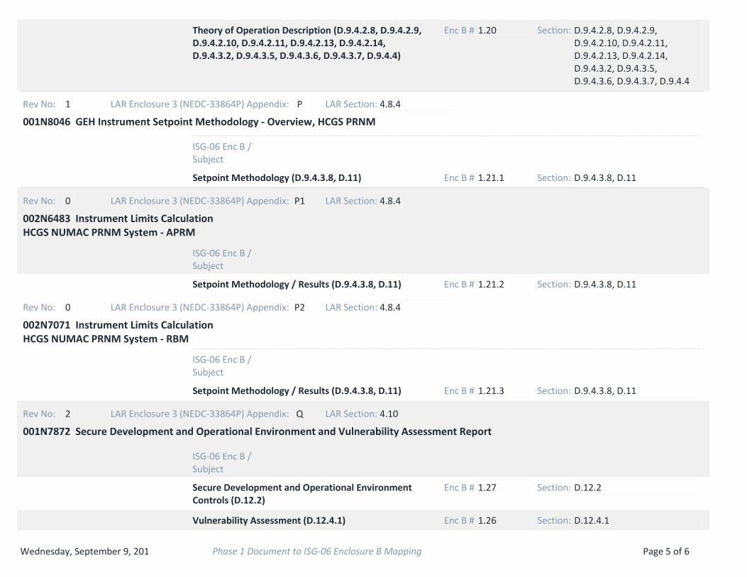
1.20Theory of Operation Description (D.9.4.2.8, D.9.4.2.9, D.9.4.2.10, D.9.4.2.11, D.9.4.2.13, D.9.4.2.14, D.9.4.3.2, D.9.4.3.5, D.9.4.3.6, D.9.4.3.7, D.9.4.4)
Enc B # Section: D.9.4.2.8, D.9.4.2.9, D.9.4.2.10, D.9.4.2.11, D.9.4.2.13, D.9.4.2.14, D.9.4.3.2, D.9.4.3.5, D.9.4.3.6, D.9.4.3.7, D.9.4.4
001N8046 GEH Instrument Setpoint Methodology ‐ Overview, HCGS PRNM
Rev No: 1 LAR Enclosure 3 (NEDC‐33864P) Appendix: P
ISG‐06 Enc B / Subject
LAR Section: 4.8.4
1.21.1Setpoint Methodology (D.9.4.3.8, D.11) Enc B # Section: D.9.4.3.8, D.11
002N6483 Instrument Limits Calculation HCGS NUMAC PRNM System ‐ APRM
Rev No: 0 LAR Enclosure 3 (NEDC‐33864P) Appendix: P1
ISG‐06 Enc B / Subject
LAR Section: 4.8.4
1.21.2Setpoint Methodology / Results (D.9.4.3.8, D.11) Enc B # Section: D.9.4.3.8, D.11
002N7071 Instrument Limits Calculation HCGS NUMAC PRNM System ‐ RBM
Rev No: 0 LAR Enclosure 3 (NEDC‐33864P) Appendix: P2
ISG‐06 Enc B / Subject
LAR Section: 4.8.4
1.21.3Setpoint Methodology / Results (D.9.4.3.8, D.11) Enc B # Section: D.9.4.3.8, D.11
001N7872 Secure Development and Operational Environment and Vulnerability Assessment Report
Rev No: 2 LAR Enclosure 3 (NEDC‐33864P) Appendix: Q
ISG‐06 Enc B / Subject
LAR Section: 4.10
1.27Secure Development and Operational Environment Controls (D.12.2)
Enc B # Section: D.12.2
1.26Vulnerability Assessment (D.12.4.1) Enc B # Section: D.12.4.1
Wednesday, September 9, 201 Page 5 of 6Phase 1 Document to ISG‐06 Enclosure B Mapping

001N8420 HCGS Plant Specific Responses Required by PRNM LTR
Rev No: 1 LAR Enclosure 3 (NEDC‐33864P) Appendix: R
ISG‐06 Enc B / Subject
LAR Section: 4.1.2.1
NAPRNM Plant Specific Response (LTR) Enc B # Section:
001N8296 Supplemental Information for ARTS for HCGS
Rev No: 3 LAR Enclosure 3 (NEDC‐33864P) Appendix: S
ISG‐06 Enc B / Subject
LAR Section: 4.1.2.3
NAARTS Justification Enc B # Section:
000N3922 HCGS Thermal Hydraulic Stability, DSS‐CD Evaluation
Rev No: 1 LAR Enclosure 3 (NEDC‐33864P) Appendix: T
ISG‐06 Enc B / Subject
LAR Section: 4.1.2.2
NADSS‐CD Evaluation Enc B # Section:
Wednesday, September 9, 201 Page 6 of 6Phase 1 Document to ISG‐06 Enclosure B Mapping

Enclosure 2 LAR H15-01 LR-N15-0178
NEDO-33864, Hope Creek Generating Station NUMAC PRNM Upgrade – Non-Proprietary

Enclosure 3 Contains Proprietary Information to be Withheld from Public Disclosure Pursuant to 10 CFR 2.390
Enclosure 3 LAR H15-01 LR-N15-0178
NEDC-33864P, Hope Creek Generating Station NUMAC PRNM Upgrade – Proprietary
This Enclosure contains proprietary information of GE-Hitachi Nuclear Energy (GEH).