Embed Size (px)
Citation preview
16 Transportation Research Record 783
Horizontal Drains and Horizontal Drilling:
An Overview
DAVID L. ROYSTER
Subsurface water may act in many ways to reduce the stability of cuts and embankments. Among these are decrease in cohesion, subsurface erosion, lateral pressure in fractures and joints, and excess pore-water pressure. One way of removing subsurface water is to use horizontal drains, which are holes drilled into an embankment or cut slope and cased with a perforated-metal or slottedplastic liner. The equipment, materials, and procedures used in the drilling and installation of horizontal drains have been improved and refined considerably since the California Division of Highways first introduced the Hydrauger in 1939. The development of polyvinyl chloride pipe, improvements in drill bits and drill stem, and the development of drilling machines capable of producing high thrust and torque have made subsurface drainage a significant and economical alternative in the repair and prevention of some types of landslides.
Water in all its forms (rain, snow, fog, ice, etc.) and in all its occurrences (streams, lakes, oceans, the subsurface, etc.) is the single most troublesome and perplexing substance that must be dealt with by transportation engineers. Of all these occurrences, subsurface water is probably the most perplexing because it is the least predictable, especially as it relates to the stability of cuts and embankments in geologically complex areas.
Subsurface water may act in many ways to reduce the stability of cuts and embankments. These include subsurface erosion, lateral pressure in fractures and joints, decrease in cohesion, reduction in moisture tension, viscous drag due to seepage flow, and excess pore-water pressure (l). By far the most common and significant of these is excess pore-water pressure, which is also referred to as neutral stress and is defined as "the stress transmitted through the fluid that fills the voids between particles of a soil or rock mass" (2)-. Pore-water pressure increases in a cut or embankm;nt when what may be termed the normal balance among infiltration, migration, and discharge is upset. This can happen rather suddenly during periods of heavy rain when there is high infiltration, or it may develop over longer periods of time due to blockage that results, for example, from consolidation along the contact or along a zone between an embankment and its underlying foundation. A reduction in stability, often to the point of failure, frequently accompanies excess increases in pore-water pressure.
One way of reducing excess pore-water pressure and high seepage forces created by perched water tables or of lowering the normal water table is through the use of horizontal drains. Horizontal drains are holes drilled into an embankment or cut slope and cased with a perforated-metal or slotted-plastic liner.
Although horizontal drains have been used in the stabilization of landslides since about 1939, when the California Division of Highways introduced the Hydrauger (]), the method did not begin to gain wide acceptance for use on a large scale by highway engineers, at least in the eastern states, until many years later. The Tennessee Department of Transportation (TOOT) first used horizontal drains, for example, as recently as 1972 when a series of embankment failures occurred along Interstate 75 in Campbell County (4-7). Drains on this project, which totaled approximately 18 288 m (60 ooo ft) in length, were used in conjunction with rock buttresses. Some drains extended as far as 183 m (600 ft) and initially produced flows as great as
26.4 L/min (7 gal/ min). Since 1972, TOOT has installed horizontal drains that total more than 53 000 m (175 000 ft) in length. Of the other eastern states, there has been rather widespread use in North Carolina, Kentucky, New York, Virginia, and Mississippi since the early to middle 1970s.
HISTORICAL DEVELOPMENT
Ear ly Equipment , Material.a , a nd Procedu r es
According to Smith and Stafford (,~), the first horizontal drilling rig used in California (the Hydrauger) was a rotary drill mounted on a racked frame in a way that permitted a revolving drill bit to be advanced into the slope by using a hand-operated ratchet lever while water was pumped through the drill rod to cool the bit and wash the cuttings from the hole. Sections of drill rod 1.5 m (5 ft) long were added as the drilling proceeded. The first holes were drilled with a 51-mm (2-in) bit and then reamed to 152 mm (6 in) prior to being cased with a 102-mm (4-in) perforated-metal pipe. It was soon determined that it was more practical to perform the drilling in one operation. This resulted in the development of a 102-mm modified fishtail bit, which was improved over the years by being hardened with various types of alloys. In 1949 the tri-cone roller bit became available and was used in drilling harder materials.
With the improvement of the fishtail bit and the development of the roller bit came further advances. For example, the 102-mm casing was replaced by 51-mm casing. It consisted of standard black pipe perforated with holes 10 mm (0.4 in) in diameter on 76-mm (3-in) spacings drilled in three rows at the quarter points. The pipe was furnished in lengths of 4.8-7.3 m (16-24 ft) without threads or couplings. The casing was then butt-welded as it was jacked into the hole. S~ith and Stafford (.!!_) state that the reason for welding the joints rather than using couplings was to hold the perforation rows in alignment and in an upright position.
Since the Hydrauger could be used in only the more-cohesive soils and soft rock, the California Division of Highways developed a more-powerful and versatile machine. This drill, first used in 1951, was a self-propelled unit powered by a 60-hp (45-kW) gasoline engine and equipped with a hydraulic feed to advance the continuous flight augers, which did not require a drilling fluid. In 1953 this machine was further modified so that regular rotary drilling could be accomplished by using N-rod and roller bits. Further improvements were made over the following several years. These involved the design and construction of a machine that had such features as a transmission that permitted control of speed of rotation over a wide range; a hydraulic feed with a minimum L 8-m (6-ft) stroke capable of exerting a thrust of 17 792 N (4000 lbf); a chuck that could be easily interchanged to accommodate A-rod, N-rod, or casing; and spuds for maintaining alignment.
Present Equ ipment , Materia l s, a nd Procedures
The equipment, materials, and procedures used in the
Transportation Research Record 783
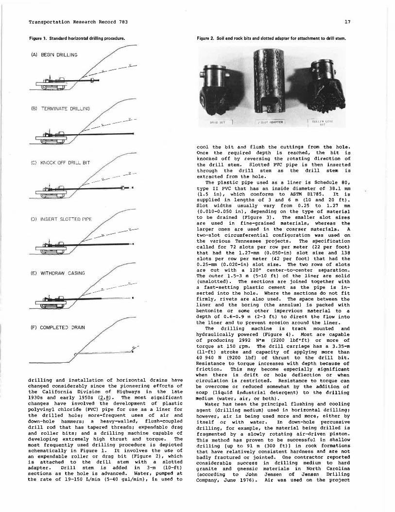
Figure 1. Standard horizontal drilling procedure.
(A) BEGIN DRILLING
(B) TERMINATE DRILLING
(C) KNOCK OFF DRILL BIT
-
(D) INSERT SLOTTED PIPE
(E) WITHDRAW CASING
(Fl COMPLETED DRAIN
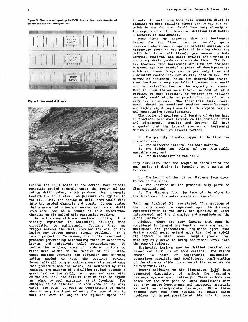
drilling and installation of horizontal drains have changed considerably since the pioneering efforts of the California Division of Highways in the late 1930s and early 1950s (~,.!!_). The most significant changes have involved the development of plastic polyvinyl chloride (PVC) pipe for use as a liner for the drilled hole; more-frequent uses of air and down-hole hanuners; a heavy-walled, flush-coupled drill rod that has tapered threads; expendable drag and roller bits; and a drilling machine capable of developing extremely high thrust and torque. The most frequently used drilling procedure is depicted schematically in Figure 1. It involves the use of an expendable roller or drag bit (Figure 2), which is attached to the drill stem with a slotted adapter. Drill stem is added in 3-m (10-ft) sections as the hole is advanced. Water, pumped at the rate of 19-150 L/min (5-40 gal/min), is used to
17
Figure 2. Soil and rock bits and slotted adapter for attachment to drill stem.
UH.\G HIT J -$10( .\ l).\ 'P f (ft C"rlut 1 I H CO\I ' 1111
cool the bit and flush the cuttings from the hole. Once the required depth is reached, the bit is knocked off by reversing the rotating direction of the drill stem. Slotted PVC pipe is then inserted through the drill stem as the drill stem is extracted from the hole.
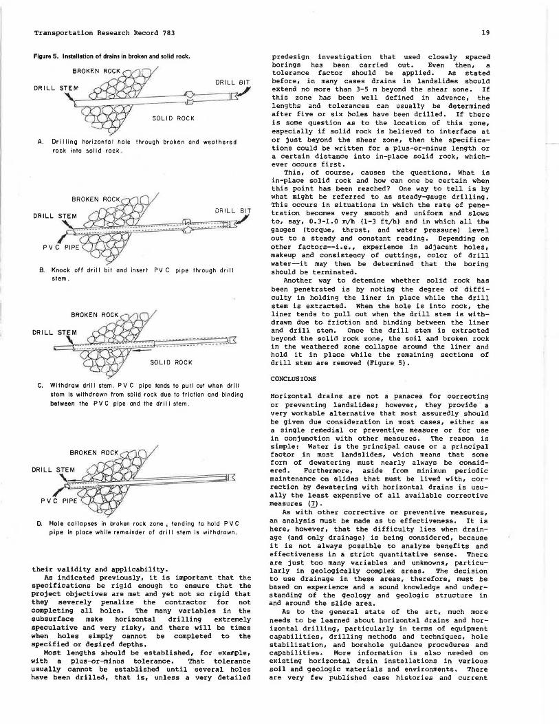
The plastic pipe used as a liner is Schedule 80, type II PVC that has an inside diameter of 38.1 nun (1.5 in), which conforms to ASTM Dl785. It is supplied in lengths of 3 and 6 m (10 and 20 ft) • Slot widths usually vary from 0.25 to 1.27 nun (0.010-0.050 in), depending on the type of material to be drained (Figure 3). The smaller slot sizes are used in fine-grained materials, whereas the larger ones are used in the coarser materials. A two-slot circumferential configuration was used on the various Tennessee projects. The specification called for 72 slots per row per meter (22 per foot) that had the 1. 27-nun (O. 050-in) slot size and 138 slots per row per meter (42 per foot) that had the 0.25-mm (0.020-in) slot size. The two rows of slots are cut with a 120° center-to-center separation. The outer 1. 5-3 m (5-10 ft) of the liner are solid (unslotted). The sections are joined together with a fast-setting plastic cement as the pipe is inserted into the hole. Where the sections do not fit firmly, rivets are also used. The space between the liner and the boring (the annulus) is packed with bentonite or some other impervious material to a depth of 0.6-0.9 m (2-3 ft) to direct the flow into the liner and to prevent erosion around the liner.
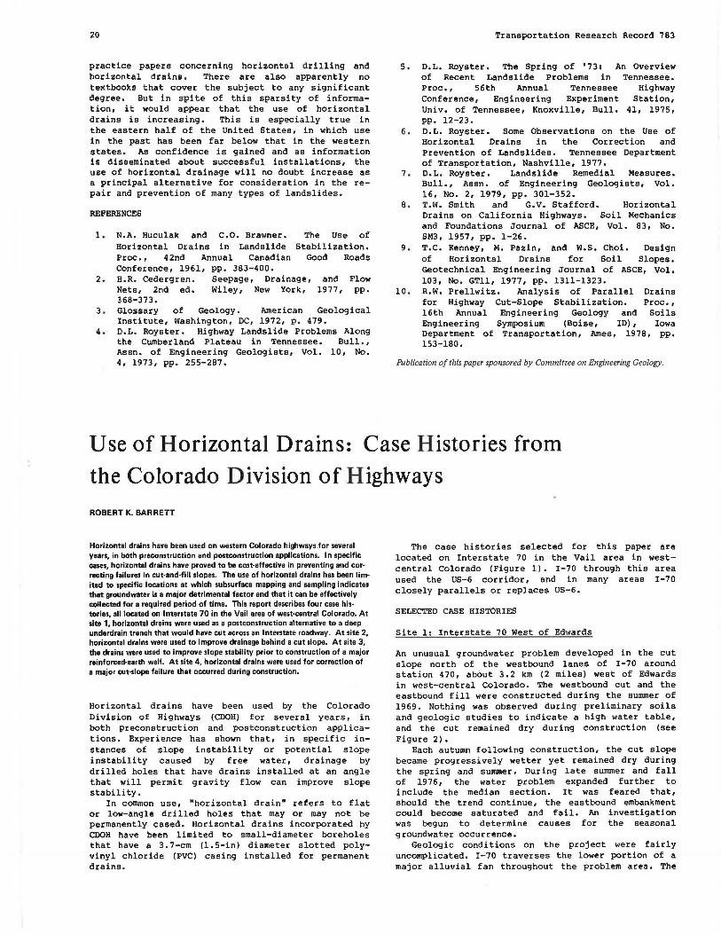
The drilling machine is track mounted and hydraulically powered (Figure 4). Most are capable of producing 2992 N"m (2200 lbf•ft) or more of torque at 150 rpm. The drill carriage has a 3.35-m (ll-ft) stroke and capacity of applying more than 40 940 N (9200 lbf) of thrust to the drill bit. Resistance to torque increases with depth because of friction. This may become especially significant when there is drift or hole deflection or when circulation is restricted. Resistance to torque can be overcome or reduced somewhat by the addition of soap (liquid industrial detergent) to the drilling medium (water, air, or both).
Water has been the principal flushing and cooling agent (drilling medium) used in horizontal drilling; however, air is being used more and more, either by itself or with water. In down-hole percussive drilling, for example, the material being drilled is fragmented by a slowly rotating air-driven piston. This method has proven to be successful in shallow drilling (up to 91 m (300 ft) J in rock formations that have relatively consistent hardness and are not badly fractured or jointed. One contractor reported considerable success in drilling medium to hard granite and gnessic materials in North Carolina (according to John Jensen of Jensen Drilling Company, June 1976). Air was used on the project
18
Figure 3. Slot sizes and spacings for PVC pipe that has inside diameter of 38 mm and two·row configuration.
( ( ( ( ( ( ( l l l I ~• II II•
i:llmm (.020')
1r·r"'":·111
.Z5mm (.010")
Figure 4. Horizontal drilling rig.
l l l l ) ) ) ) )) ))
l 1 ll \.11 ,/J
because the drill holes in the softer, more-friable materials eroded severely under the action of the return drill water, which produced deep channels beneath the drill stem. As pressure was applied to the drill bit, the string of drill stem would flex into the eroded channels and break. Jensen states that a number of holes and several sections of drill stem were lost as a result of this phenomenon. Changing to air solved this particular problem.
As is the case with most vertical drilling, it is vi tally important in horizontal drilling that circulation be maintained. Cuttings that get trapped between the drill stem and the wall of the boring may create severe torque problems. In a recent project in Tennessee, the driller was having problems penetrating alternating zones of weathered, broken, and relatively solid metasediments. To reduce the problem, rows of hardened buttons or beads were welded on the section of drill stem. These buttons provided the agitation and churning action needed to keep the cuttings moving. Essentially all torque problems were eliminated once this procedure was initiated. As indicated by this example, the success of a drilling project depends a great deal on the skill, technique, and creativity of the driller. The driller must be able to adjust and adapt to each situation as it develops. For example, it is essential to know when to use air, water, and soap, as well as combinations of each 1 when to vary the input of each1 the type of bit to use1 and when to adjust the spindle speed and
Transportation Research Record 783
thrust. It would seem that such knowledge would be academic to most drilling firms1 yet it may not be, which is why the user should look very closely at the experience of the potential drilling firm before a contract is consummated.
Many firms and agencies that use horizontal drains for the first time are usually quite concerned about such things as borehole guidance and trajectory (even to the point of knowing where the drill bit is at all times) 1 preciseness in hole lengths, spacings, and slope angles; and whether or not every drain produces a sizable flow. The fact is, however, that horizontal drilling for drainage purposes has not reached a point of development at which all these things can be precisely known and absolutely controlled, nor do they need to be. The survey of horizontal holes for determining trajectory involves a very specialized process that would not be cost-effective in the majority of cases. Even if these things were known, the cost of using wedging, or whip stocking, to deflect the drilling assembly would simply be prohibitive in all but a very few situations. The first-time user, therefore, should be cautioned against overrefinements and highly rigid requirements in developing designs and establishing specifications.
The choice of spacings and lengths of drains has, in practice, been done largely on the basis of trial and adjustment. Huculak and Brawner (1) have suggested that the lateral spacing of ho~izontal drains is dependent on several factors:
l. The quantity of water tapped in the first few installations,
2. The suspected internal drainage pattern, 3. The height and volume of the potentially
unstable area, and 4. The permeability of the soil.
They also state that the length of installation for any series of drains is dependent on a number of factors:
l. The height of the cut or distance from crown to toe of the slide,
2. The location of the probable slip plane or firm material, and
3. The distance from the face of the slope to . the location of the water source or reservoir.
Smith and Stafford (~) have stated, "The spacings of the drains should be dependent upon the drainage characteristics of the soil, the quantity of water intercepted, and the character and magnitude of the slide involved."
Although there are many factors that must be considered in determining lengths, many engineering geologists and geotechnical engineers agree that drains should never extend more than 3-5 m (10-15 ft) beyond the shear zone. Lengths greater than this may only serve to bring additional water into the zone of failure.
Horizontal borings may be drilled parallel or fanned out from one or more centers. The method chosen is based on topographic expression, subsurface materials and conditions, configuration of the slope or slide, location of the water source or reservoir, etc.
Recent additions to the literature (!,10) have presented discussions of methods for designing drainage systems quantitatively. These methods are based for the most part on ideal conditions1 that is, they assume homogeneous and isotropic materials as well as steady-state drainage. Since these methods have not been applied to actual field problems, it is not possible at this time to judge
Transportation Research Record 783
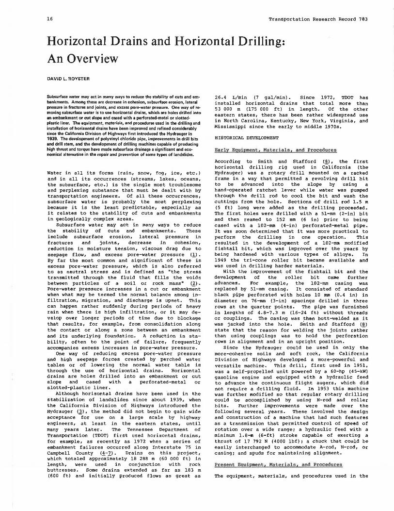
Figure 5. Installation of drains in broken and solid rock.
BROKEN
DRILL BIT DRILL
\,_~~ISJL~--::5t::==~CT,/
SOLID ROCK
A. Drilling horizontal hole through broken ond weathered rock into solid rock .
8. Knock off drill bit and insert PVC pipe through drill stem .
BROKEN
DRILL
SOLID ROCK
C. Withdraw drill stem. PVC pipe tends to pull out when drill
stem is withdrawn from solid rock due lo friction and binding
between the PVC pipe and the drill stem .
D. Hole collapses in broken rock zone , tending to hold PVC pipe in place while remainder of drill stem is withdrawn.
their validity and applicability. As indicated previously, it is important that the
specifications be rigid enough to ensure that the project objectives are met and yet not so rigid that they severely penalize the contractor for not completing all holes. The many variables in the subsurface make horizontal drilling extremely speculative and very risky, and there will be times when holes simply cannot be completed to the specified or desired depths.
Most lengths should be established, for example, with a plus-or-minus tolerance. That tolerance usually cannot be established until several holes have been drilled, that is, unless a very detailed
19
predesign investigation that used closely spaced borings has been carried out. Even then, a tolerance factor should be applied. As stated before, in many cases drains in landslides should extend no more than 3-5 rn beyond the shear zone. If this zone has been well defined in advance, the lengths and tolerances can usually be determined after five or six holes have been drilled. If there is some question as to the location of this zone, especially if solid rock is believed to interface at or just beyond the shear zone, then the specifications could be written for a plus-or-minus length or a certain distance into in-place solid rock, whichever occurs first.
This, of course, causes the questions, What is in-place solid rock and how can one be certain when this point has been reached? One way to tell is by what might be referred to as steady-<Jauge drilling. This occurs in situations in which the rate of penetration becomes very smooth and uniform and slows to, say, 0.3-1.0 rn/h (1-3 ft/hl and in which all the gauges (torque, thrust, and water pressure) level out to a steady and constant reading. Depending on other factors--i.e., experience in adjacent holes, makeup and consistency of cuttings, color of drill water--it may then be determined that the boring should be terminated.
Another way to deternine whether solid rock has been penetrated is by noting the degree of difficulty in holding the liner in place while the drill stern is extracted. When the hole is into rock, the liner tends to pull out when the drill stern is withdrawn due to friction and binding between the liner and drill stern. Once the drill stern is extracted beyond the solid rock zone, the soil and broken rock in the weathered zone collapse around the liner and hold it in place while the remaining sections of drill stern are removed (Figure 5).
CONCLUSIONS
Horizontal drains are not a panacea for correcting or preventing landslides; however, they provide a very workable alternative that most assuredly should be given due consideration in most cases, either as a single remedial or preventi.ve measure or for use in conjunction with other measures. The reason is simple: Water is the principal cause or a principal factor in most landslides, which means that some form of dewatering must nearly always be considered. Furthermore, aside from minimum periodic maintenance on slides that must be lived with, correction by dewatering with horizontal drains is usually the least expensive of all available corrective measures <ll •
As with other corrective or preventive measures, an analysis must be made as to effectiveness. It is here, however, that the difficulty lies when drainage (and only drainage) is being considered, because it is not always possible to analyze benefits and effectiveness in a strict quantitative sense. There are just too many variables and unknowns, particularly in geologically complex areas. The decision to use drainage in these areas, therefore, must be based on experience and a sound knowledge and understanding of the geology and geologic structure in and around the slide area.
As to the general state of the art, much more needs to be learned about horizontal drains and horizontal drilling, particularly in terms of equipment capabilities, drilling methods and techniques, hole stabilization, and borehole guidance procedures and capabilities. More information is also needed on existing horizontal drain installations in various soil and geologic materials and environments. There are very few published case histories and current
20
practice papers concerning horizontal drilling and horizontal drains. There are also apparently no textbooks that cover the subject to any significant degree. But in spite of this sparsity of information, it would appear that the use of horizontal drains is increasing. This is especially true in the eastern half of the United States, in which use in the past has been far below that in the western states. As confidence is gained and as information is disseminated about successful installations, the use of horizontal drainage will no doubt increase as a principal alternative for consideration in the repair and prevention of many types of landslides.
REFERENCES
1. N.A. Huculak and c.o. Brawner. The Use of Horizontal Drains in Landslide Stabilization. Proc., 42nd Annual Canadian Good Roads Conference, 1961, pp. 383-400.
2. H.R. Cedergren. Seepage, Drainage, and Flow Nets, 2nd ed. Wiley, New York, 1977, pp. 368-373.
3 . Glossary of Geology. American Geological Institute, Washington, DC, 1972, p. 479.
4. D.L. Royster. Highway Landslide Problems Along the Cumberland Plateau in Tennessee. Bull., Assn. of Engineering Geologists, Vol. 10, No. 4, 1973, pp. 255-287.
Transportation Research Record 783
5. D.L. Royster. The Spring of '73: An Overview of Recent Landslide Problems in Tennessee. Proc., 56th Annual Tennessee Highway Conference, Engineering Experiment Station, Univ. of Tennessee, Knoxville, Bull. 41, 1975, pp. 12-23.
6. D. L. Royster. Some Observations on the Use of Horizontal Drains in the Correction and Prevention of Landslides. Tennessee Department of Transportation, Nashville, 1977.
7. D.L. Royster. Landslide Remedial Measures. Bull., Assn. of Engineering Geologists, Vol. 16, No. 2, 1979, pp. 301-352.
8. T.W. Smith and G.V. Stafford. Horizontal Drains on California Highways. Soil Mechanics and Foundations Journal of ASCE, Vol. 83, No. SM3, 1957, pp. 1-26.
9. T.C. Kenney, M. Pazin, and w.s. Choi. Design of Horizontal Drains for Soil Slopes. Geotechnical Engineering Journal of ASCE, Vol. 103, No. GTll, 1977, pp. 1311-1323.
10. R.W. Prellwitz. Analysis of Parallel Drains for Highway Cut-Slope Stabilization. Proc., 16th Annual Engineering Geology and Soils Engineering Symposium (Boise, ID), Iowa Department of Transportation, Ames, 1978, pp. 153-180.
Publication of this paper sponsored by Committee on Engineering Geology.
Use of Horizontal Drains: Case Histories from the Colorado Division of Highways
ROBERT K. BARRETT
Horizontal drains have been used on western Colorado highways for several years, in both preconstruction and postconstruction applications. In specific cases, horizontal drains have proved to be cost·effective in preventing and correcting failures in cut-and-fill slopes. The use of horizontal drains has been limited to specific locations at which subsurface mapping and sampling indicates that groundwater is a major detrimental factor and that it can be effectively collected for a required period of time. This report describes four case histories, all located on Interstate 70 in the Vail area of west-central Colorado. At site 1, horizontal drains were used as a postconstruction alternative to a deep underdrain trench that would have cut across an Interstate roadway. At site 2, horizontal drains were used to improve drainage behind a cut slope. At site 3, the drains were used to improve slope stability prior to construction of a major reinforced-earth wall. At site 4, horizontal drains were used for correction of a major cut-slope failure that occurred during construction.
Horizontal drains have been used by the Colorado Division of Highways (CDOH) for several years, in both preconstruction and postconstruction applications. Experience has shown that, in specific instances of slope instability or potential slope instability caused by free water, drainage by drilled holes that have drains installed at an angle that will permit gravity flow can improve slope stability.
In common use, "horizontal drain" refers to flat or low-angle drilled holes that may or may not be permanently cased. Horizontal drains incorporated by CDOH have been limited to small-diameter boreholes that have a 3. 7-cm (1. 5-in) diameter slotted polyvinyl chloride (PVC) casing installed for permanent drains.
The case histories selected for this paper are located on Interstate 70 in the Vail area in westcentral Colorado (Figure 1). I-70 through this area used the US-6 corridor, and in many areas I-70 closely parallels or replaces US-6.
SELECTED CASE HISTORIES
Site 1: Interstate 70 West of Edwards
An unusual groundwater problem developed in the cut slope north of the westbound lanes of I-70 around station 470, about 3.2 km (2 miles) west of Edwards in west-central Colorado. The westbound cut and the eastbound fill were constructed during the summer of 1969. Nothing was observed during preliminary soils and geologic studies to indicate a high water table, and the cut remained dry during construction (see Figure 2).
Each autumn following construction, the cut slope became progressively wetter yet remained dry during the spring and summer. During late summer and fall of 1976, the water problem expanded further to include the median section. It was feared that, should the trend continue, the eastbound embankment could become saturated and fail. An investigation was begun to determine causes for the seasonal groundwater occurrence.
Geologic conditions on the project were fairly uncomplicated. I-70 traverses the lower portion of a major alluvial fan throughout the problem area. The


![Effect of Horizontal Drains on Upstream Slope Stability ... · upstream slope and making the equipotential lines tend to become horizontal. This effect is shown in figure 5. [5] Duncan](https://img.pdfslide.net/doc/110x75/600eca95e86f657b4b16071a/effect-of-horizontal-drains-on-upstream-slope-stability-upstream-slope-and-making.jpg)