Embed Size (px)
Citation preview

436
UNIT 8How do we harness chemical energy?
The core concepts, ideas, and methodologies introduced in previous Units of this course can be applied to design, implement, and evaluate strategies to harness energy from chemical reactions. The proper selection of materials and conditions critically depends on the analysis of diverse fac-tors that may influence the directionality, extent, and rate of different chemical processes.
Modern devices used to harness chemical energy often rely on reactions that result in the transfer of electrons from one system to another. These batteries transform chemical en-ergy into electrical energy and are used to power watches, cell phones, tablet computers, and electric cars in modern times. The current challenge is to produce devices that can store energy in large amounts per unit mass and that can deliver that energy in short periods of time.
The central goal of Unit 8 is to create opportunities for you to apply the knowledge developed in this course to the analysis of electrochemical processes and devices used to harness energy.
By Avda (Own work) [Share Alike 3.0] via Wikimedia Commons
437
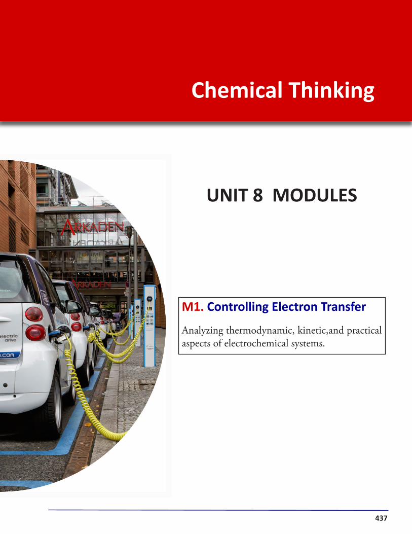
Chemical Thinking
UNIT 8 MODULES
M1. Controlling Electron Transfer
Analyzing thermodynamic, kinetic,and practical aspects of electrochemical systems.

438
Controlling Electron Transfer
U8:
MO
DULE
1 Most of the energy used by modern societies results from the transformation of chemical energy into thermal, electrical, or light energy. The major proportion of that energy is generated by combustion of fossil fuels rich in hydrocarbons that react with oxygen in the atmosphere and produce carbon dioxide and water in a very exother-mic process. Concerns with the role that CO2 has on global warming and climate change on Earth has sparked interest in the development of more durable and power-ful batteries and fuel cells. These devices transform chemical energy into electrical energy without generating greenhouse gases.
The design of electrical batteries and fuel cells demands a very good under-standing of the thermodynamics and kinetics of the processes that take place inside these devices. The challenges that scientists and engineers face to improve energy storage and delivery are not small. Chemical reactions inside batteries and fuel cells involve substances in different states of matter that should interact effectively over time and under different conditions. Rechargeable batteries require chemical reactions that can be reversed without major deterioration of components. Reac-tants and products should be contained within the device at all times and any heat produced by internal processes should be quickly dissipated to avoid damaging the battery and major hazards. In Unit 8 we will explore how chemical thinking can be used to face some of these challenges.
THE CHALLENGE Bio-Batteries
The understanding of how plants and animals store and use energy has guided the development of bio-batteries that mimic biological systems.
• Which biochemical processes for energy storage do you know?• What are some potential advantages and disadvantages of bio-batteries
compared to conventional batteries?
Share and discuss your ideas with one of your classmates.
This module will help you develop the type of chemical thinking that is used to answer questions similar to those posed in the challenge. In particular, the central goal of Module 1 is to help you apply your knowledge in the analysis of electrochemical processes used to harness chemical energy.
By KyloDeel (Ow
n work)
[Public Domain] via W
ikimedia Com
mons

439U8 How do we harness chemical energy?Chemical Thinking
Electron Transfer and Redistribution LET’S THINKConsider the addition reaction represented to the right:
• Assign partial charges to all the atoms in reactants and products.
• Describe the major changes in electron density that you observe.• Evaluate whether you can determine how many electrons were transferred in this process
and how they were redistributed.• Highlight advantages and disadvantages to this approach to analyze electron transfer.
Share and discuss your ideas with a classmate, and clearly justify your reasoning.
Analyzing Electron Distribution
Chemical reactions result from interactions between regions with different elec-tron density in the reacting particles. These interactions often lead to the breaking of some chemical bonds and to the formation of new ones. In these processes, valence electrons are redistributed between some atoms and their potential energy changes. The chemical reactions commonly used to generate energy in modern societies are exothermic processes in which energy is released due to the movement of electrons from high to low potential energy states. Thus, identifying chemical species in which electrons occupy states with different potential energies can help us select combination of reactants that will react exo-thermically with each other.
Electrons are negatively charged particles that are attracted to centers with a partial or net positive electric charge. Electrical forces thus induce movement of electrons from regions with a partial or net negative charge to areas with a partial or net positive charge. From an energetic perspec-tive, the potential energy of electrons is higher in areas with a partial or net nega-tive charge and lower in regions with a more positive partial or net charge (Figure 8.1). Transfer of electrons should then spontaneously occur from high potential energy states to low potential energy states, but these processes often face kinetic activation barriers that need to be overcome for the transfer to happen.
We can identify areas of partial positive or negative charge in molecules by analyzing their composition and structure. This allows us to, for example, identify electrophilic and nucleophilic centers as we did it in Unit 7. This approach, how-ever, has limitations as it does not make explicit how many electrons are transferred between reactants and how they are redistributed during a chemical reaction.
Figure 8.1 In this reaction, electrons in the double bond (higher potential energy) move towards the chlorine atom where they occupy lower potential energy states.
Analysis of the partial charges on different atoms in reactants and products provides qualitative information about changes in electron density as a result of a chemical reaction. However, chemists have developed other strategies that facili-tate the identification of electron-rich and electron-poor sites in molecules and provide more insights into how electrons are transferred or redistributed in chemi-cal reactions.
+ HBr

440 MODULE 1 Controlling Electron Transfer
A useful strategy to analyze electron distribution in molecules and ions is to calculate the oxidation state (or oxidation number) of each atom present in the system. The oxidation state indicates the total number of valence electrons that an atom would gain or lose when forming chemical bonds if we assumed that bonding electrons belong to the most electronegative atom in each bond. Thus, the oxidation state represents the charge of the atoms if we assumed that all bonds are ionic. The oxidation state is often a fictitious quantity but it provides useful information about electron distribution in chemical species.
To calculate the oxidation state (OS) of an atom in a system we take the dif-ference between the number of valence electrons in the isolated atom and the number of valence electrons in the bonded atom (assuming ionic bonding):
OS = Number of valence electrons in the isolated atom – Number of valence electrons in the bonded atom
Let us apply this relationship to calculate the oxidation state of all atoms in a molecule of ethanol CH3CH2OH. If we assign the different valence electrons to the most electronegative atom in each bond and split bonding electrons equally between atoms of the same type, as shown in Figure 8.2, the oxidation state for each atom in the molecule can be calculated as:
OS(H) = 1 – 0 = +1
OS(O) = 6 – 8 = –2
OS(C1) = 4 – 7 = –3
OS(C2) = 4 – 5 = –1
The number of valence electrons in the isolated atoms can be inferred from their position in the periodic table. The number of valence electrons in the bonded state is determined by counting the electrons assigned to each atom based on relative electronegativity values (Figure 8.2). Notice that the carbon atoms in ethanol do not have the same oxidation states, making explicit the presence of an electron-poor site (C2) in this molecule. However, the oxidation states determined above do not correspond to actual electric charges on any of the atoms.
LET’S THINK Oxidation State
Determine the oxidation state of each atom in the species shown to the right:
• What major patterns do you observe?
• What is the relationship between the oxidation states and the net charge of a molecule or ion?
Clearly justify your ideas.
Figure 8.2 Assignation of valence electrons to different atoms in the ethanol molecule assum-ing ionic bonding.
1 2

441U8 How do we harness chemical energy?Chemical Thinking
The determination of the oxidation states of many molecules and ions reveals some basic patterns that simplify the calculation of this quantity for any atom in any molecular species. These simplifying rules are listed below:
a) Elementary Substances: The oxidation state of atoms present in the par-ticles of elementary substances, such as He(g), O2(g), Na(s) or He(g) is always zero. For example, in the case of the molecule of Cl2 (Figure 8.3):
OS(Cl) = 7 – 7 = 0
b) Monoatomic Ions: The oxidation state of monoatomic ions present in ionic compounds or as free ions in solution, such as Na+, Cl–, Mg2+, S2–, is the same as the net charge of the ion. Thus:
OS(Al3+) = +3
c) Reference Atoms: The oxidation state of some atoms is generally a fixed number in many chemical compounds. These values can be used to infer the oxi-dation states for other atoms present in the same chemical species:
OS(Alkali Metals: Li, Na, K ..) = +1OS(Alkaline Earth Metals: Mg, Ca, Sr ..) = +2
OS(H) = +1OS(O) = –2 OS(F) = –1
d) Net Charge: The algebraic sum of the oxidation states of all the atoms pres-ent in a molecule or ion should be equal to the net charge of the chemical species. If the molecule has no charge, the algebraic sum of the oxidation states should be equal to zero. If the particle is a polyatomic ion, the algebraic sum of the oxida-tion states should be equal to the charge of the ion. Consider, for example, the molecule of ethanol CH3CH2OH in Figure 8.2:
Net Charge = SOS = 6 x OS(H) + OS(C1)+ OS(C2)+ OS(O)
Net Charge = SOS = 6 x (+1) + (–3) + (–1) + (–2) = 0
Basic Rules LET’S THINKThe following chemical species are commonly used in the synthesis or transformation of alcohols:
H2 H2CrO4 KMnO4 NaOCl
The following species are polyatomic ions present in different electric batteries:OH– SO4
2– NO3– NH4
+
• Determine the oxidation state of each atom in these different chemical species.
Share and discuss your ideas with a classmate, and clearly justify your reasoning.
Figure 8.3 Assignation of va-lence electrons to the atoms in the Cl2 molecule.

442 MODULE 1 Controlling Electron Transfer
Redox reactions tend to be exothermic reactions due to the movement of electrons from higher to lower potential energy states, and thus may be used to harness chemical energy. The following two chemical reactions are typical examples of these types of processes (oxidation states for each atom are shown):
C H4 + 2 O2 C O2 + 2 H2 O
3 H2 + N2 2 N H3
In the first of these reactions, the combustion of methane (CH4), the oxidation state of carbon atoms increases from –4 to +4, while the oxidation state of oxy-gen atoms decreases from 0 to –2. These changes indicate a transfer of electrons (or electron density) from carbon atoms to oxygen atoms during the combustion process. In the synthesis of ammonia (NH3) represented by the second reaction, electron transfer occurs from hydrogen atoms to nitrogen atoms.
During a redox reaction, the atoms that lose electrons or electron density are said to be oxidized during the process. We can recognize oxidized atoms because their oxidation state increases (it becomes less negative or more positive). In gen-eral, the term “oxidation” refers to the loss of electrons. On the other hand, the atoms that gain electrons or electron density are said to be reduced. We can recognize reduced atoms because their oxidation state decreases (it becomes less positive or more negative). In general, the term “reduction” refers to the gain of electrons. Consequently, during the combustion of CH4 carbon atoms are oxidized and oxy-gen atoms are reduced. The two reactants that exchange electrons during a redox reactions are commonly named the oxidizing agent and the reducing agent. The oxidizing agent holds the atoms that gain electrons during the process (i.e., the at-oms that are reduced), while the reducing agent holds the atoms that lose electrons as a result of the reaction (i.e., the atoms that are oxidized). In the combustion of methane, O2 is the oxidizing agent and CH4 is the reducing agent (Figure 8.4).
Figure 8.4 Oxidized and re-duced atoms, and oxidizing and reducing agents.
-4 +1 0 +4 -2 +1 -2
0 0 -3 +1CH4
+
2 O2
CO2
+
2 H2O
C Oxidized
OReduced
CH4Reducing
Agent
O2Oxidizing
Agent
LET’S THINK Electron Transfer
Consider the chemical reaction for the incomplete combustion of methanol (CH4O):
CH4O + O2 CO + 2 H2O
• Assign oxidation states to each atom in the reactants and products.• Use your results to identify which atoms lost electrons and which atoms gained electrons
during the reaction.
Share and discuss your ideas with a classmate, and clearly justify your reasoning.
Oxidation-Reduction (REDOX) Reactions
When different chemical species interact with each other, electrons may be trans-ferred from one atom to another. In this process, the oxidation state of some at-oms may change as some bonds get broken and new bonds are formed. Chemical reactions that result in changes in the oxidation state of participating atoms are classified as oxidation-reduction reactions or redox reactions.

443U8 How do we harness chemical energy?Chemical Thinking
Many redox reactions used in electric batteries to generate energy involve me-tallic and ionic species that react readily when in contact with each other. For example, when metallic zinc is added to an aqueous solution of a copper(II) salt, the following exothermic and product-favored reaction takes place:
Zn(s) + Cu2+(aq) Zn2+ (aq) + Cu(s)
Analysis of the oxidation states of reactants and products indicates that zinc atoms are oxidized and copper ions are reduced in this process. Moreover, the change in oxidation states reveals that every zinc atom loses two electrons and every copper ions gains two electrons. It is common to represent the oxidation and reduction processes as the following separate half reactions:
Zn Zn2+ + 2 e– OXIDATION Cu2+ + 2 e– Cu REDUCTION
Each half-reaction represents the chemical species involved in electron transfer and the number of electrons that are exchanged between them. By convention, elec-trons are represented in the product side in the oxidation half reaction and in the reactant side in the reduction half reaction. The number of electrons exchanged is always the same, as the electrons lost by the oxidized atoms are gained by the reduced atoms. For example, consider the reaction that takes place when metallic copper is in contact with an aqueous solution of a silver(I) salt (Figure 8.5):
Cu(s) + 2 Ag+(s) Cu2+(s) + 2 Ag(s)
In this case, the half reactions can be expressed as:
Cu Cu2+ + 2 e– OXIDATION 2 Ag+ + 2 e– 2 Ag REDUCTION
These half reactions reveal that each copper atoms provides the number of elec-trons needed to reduce two silver ions. Notice that in this case the copper atoms are the oxidized species, which suggests that the direction of electron transfer de-pends on the nature of the chemical species in interaction.
Figure 8.5 Oxidation of metallic copper in a solution of silver nitrate.
By Toby Hudson (Ow
n work)
[Sahre Alike 3.0] via Wikim
edia Comm
ons
Redox Reactions LET’S THINKConsider the following exothermic reactions :
H2 + 2 O2 2 H2OHCl + NH3 NH4Cl
CH4 + 2 H2O CO2 + 4 H2C2H4 + H2 C2H6
• In each case, determine whether the process can be classified as a redox reaction. Identify the oxidized and reduced atoms, and the oxidizing and reducing agents in redox reactions.

444 MODULE 1 Controlling Electron Transfer
Electrochemical Devices
The electron transfer that takes place during some redox reactions can be used to generate an electric current. Electrochemical devices are systems designed to con-trol the transformation of chemical energy into electrical energy. These types of devices often include three basic parts:
I. A chemical system that undergoes “oxidation”: A An+ + ne-II. A chemical system that undergoes “reduction”: Bm+ + me- BIII. A mechanism to allow and control charge transfer.
These three parts must be connected to each other to allow a controlled transfer of electrons from the system where the oxidation takes place to the system where the reduction occurs.
LET’S THINK Half-Reactions
Consider the following unbalanced redox reactions:
Al(s) + Cu2+(aq) Al3+(aq) + Cu(s)Zn(s) + H+(aq) Zn2+(aq) + H2(g)
Al(s) + Br2(l) Al3+(aq) + Br–(aq)
• Write the corresponding half reactions for each process. Identify the atoms that are oxidized and reduced, and the minimum number of each species involved in electron exchange.
Share and discuss your ideas with a classmate, and clearly justify your reasoning.
LET’S THINK An Electrochemical Cell
The image to the right depicts the basic com-ponents of a galvanic or voltaic cell, a pro-totypical electrochemical device. Although the specific chemical substances used in the cell may vary, as well as the manner in which different components are linked to each other, the underlying structure is pres-ent in most electrical batteries.
• Identify the three basic components of the electrochemical device.
• Describe and represent in detail the processes that are taking place in each of the main components of the system.
Share and discuss your ideas with a classmate, and clearly justify your reasoning.
(–)Anode
(+)Cathode
Sodium Ions Sulfate Ions
Na2SO4 paste

445U8 How do we harness chemical energy?Chemical Thinking
Charge Transfer LET’S THINK Consider the electrochemical cell depicted in Figure 8.7:
• Carefully analyze the flow of charge in this electrochemical device. Discuss how electric charge is transferred through the external circuit and through the salt bridge.
• Analyze whether the salt bridge is necessary for the electrochemical cell to work. Think of other arrangements that could be used to replace the salt bridge.
Share and discuss your ideas with a classmate, and clearly justify your reasoning.
In an electrochemical cell, the systems that undergo oxidation and reduction are physically separated from each other to avoid the direct transfer of electrons between them. Instead, they are connected via an external circuit that controls the flow of electrons from the reducing agent to the oxidizing agent. Electrons spon-taneously move from high to low potential energy states. The potential energy of charged particles is determined by the electric potential (V) at the place where they are located. The potential energy of positive charges decreases as they move from regions where the electric potential is higher or more positive to regions where the electric potential is lower or more negative. Conversely, the potential energy of negatively charged particles, such as electrons, decreases as they move from areas with a low or negative electric potential to regions with a higher or more positive electric potential (Figure 8.6).
The two main systems that comprise an electrochemical cell, also called half cells, have different electric potentials. The half cell that contains the oxidizing agent has the higher or more positive electric potential and is associated with the “cathode” of the cell (Figure 8.7). The half cell that contains the reducing agent has the lower or more negative electric potential and is associated with the “anode.” The difference in electric potential from the anode to the cathode is the electric voltage of the cell (DV) and it drives the flow of electrons from one electrode to the other. The electric voltage DV depends on the chemical nature and concentration of the species in the cell, and on temperature. DV decreases as electrons transfer from anode to cath-ode and eventually becomes zero.
When electrons are allowed to move from the anode to the cathode through the external circuit of an electrochemical cell, a charge unbalance is created. The anode becomes slightly more positive and the cathode becomes slightly more negative. This affects the distribution of ions in the aque-ous solutions of the electrochemical cell. Negative ions are repelled by the cathode and attracted by the anode, while positive ions are pulled towards the cathode and move away from the anode. This flow of ions allows the oxidation and reduction processes to continue as the posi-tive ions formed in the anode as a result of the oxidation (Cu2+ in Figure 8.7) are continuously dispersed throughout the system, and the positive ions involved in the reduction reaction (Ag+ in Figure 8.7) are pulled towards the reduction site.
Figure 8.6 Movement of charge due to a difference in electric potential.
Figure 8.7 Major components of an electrochemical cell
DV
By Shamsher Singh (O
wn w
ork) via U
C Davis ChemW
Iki
+ + + + + + + + + + + +
– – – – – – – – – – – –
High Electric Potential
Low Electric Potential
+ –

446 MODULE 1 Controlling Electron Transfer
Electrochemical Cell Potentials
The voltage DV of an electrochemical cell determines the maximum amount of electrical energy that the device may generate. DV is a measure of the chemical en-ergy transformed into electrical energy per unit of electric charge that flows from the anode to the cathode. The voltage DV is often expressed in volts (V) which are a measure of the joules (J) of energy per coulomb of charge transferred. An electrochemical cell with a DV = 2.5 V, for example, will produce 2.5 J of energy when 1 C of charge flows through its external circuit.
Given that the magnitude of the electric charge of a single electron is very small when expressed in coulombs |qe| = 1.602 x 10⁻¹⁹ C, it is common to express and calculate the energy transformed by an electrochemical cell per mole of elec-trons transferred. The magnitude of this amount of charge is known as Faraday’s constant F and it is equal to:
F = Na|qe| = 6.022 x 1023 x 1.602 x 10–19 = 9.647 x 10⁴ C/mol
where Na is Avogadro’s number. If “n” moles of electrons are transferred from the anode to the cathode in an electrochemical cell with a voltage DV, the amount of energy involved is then given by the product nFDV. This quantity is equal in magnitude to the decrease in potential energy of the electrons transferred from the anode to the cathode (Figure 8.8). This change in potential energy is a measure of the decrease in the Gibbs free energy DG of the electrochemical cell when “n” moles of electrons flow from the anode to the cathode:
(8.1) DG = – n F DV
The negative sign in this expression accounts for the decrease in the potential en-ergy of the system. This relationship highlights the importance of determining the value of DV for any electrochemical cell of interest as this quantity can be used to predict the maximum amount of electrical energy that device can produce.
LET’S THINK A Reference Cell
Consider the following information:
When an electrochemical device with the two half cells Ag(s)|Ag+(aq) (1 M) and H2(g)|H+(aq) (1 M) is built, the following processes take place and a DV is established
Anode: H2 2 H+ + 2 e- Cathode: Ag+ + e- Ag DV = 0.80 V
When an electrochemical device with the two half cells Zn(s)|Zn2+(aq) (1 M) and H2(g)|H+(aq) (1 M) is built, the following processes take place and a DV is established:
Anode: Zn Zn2+ + 2 e- Cathode: 2 H+ + 2 e- H2 DV = 0.76 V
• What would you expect to happen when an electrochemical cell is built using the half cells Ag(s) |Ag+(aq) (1 M) and Zn(s)|Zn2+(aq) (1 M). What would DV be? Justify your reasoning.
Figure 8.8 Change in free energy due to elec-tron transfer.
Anode Cathode
Epn e-
DG = – nFDV

447U8 How do we harness chemical energy?Chemical Thinking
The two electrodes in an electrochemical cell typically have different electric potentials. The electric potential of the cathode is higher than the electric potential of the anode and DV is a measure of such difference. If we build a set of electro-chemical cells that have one half cell in common and measure their associated volt-ages, we can use these data to infer the DV for any electrochemical cell built with any pair of half cells in the set. For example, consider these data:
Electrochemical Cell A: H2(g)|H+(aq) (1 M) || Cu(s)|Cu2+(aq) (1 M) Anode: H2 2 H+ + 2 e- Cathode: Cu2+ + 2 e- Cu DV = 0.34 V
Electrochemical Cell B: Zn(s)|Zn2+(aq) (1 M) || H2(g)|H+(aq) (1 M) Anode: Zn Zn2+ + 2 e- Cathode: 2 H+ + 2 e- H2 DV = 0.76 V
These data suggest that the Cu(s)|Cu2+(aq) half cell has an electric potential that is 0.34 V higher than that of the H2(g)|H+(aq) half cell, while the Zn(s)|Zn2+(aq) half cell has an electric potential that is 0.76 V lower than that of the H2(g)|H+(aq) half cell. Consequently, an electrochemical cell built with the copper and zinc half cells should have these characteristics (Figure 8.9):
Electrochemical Cell C: Zn(s)|Zn2+(aq) (1 M) || Cu(s)|Cu2+(aq) (1 M) Anode: Zn Zn2+ + 2 e- Cathode: Cu2+ + 2 e- Cu DV = 0.34 + 0.76 = 1.1 V
The DV measured using the H2(g)|H+(aq) half cell as a reference can be used to define an standard reduction potential Eo
red for any given redox pair A|An+. The magnitude of Eo
red is equal to the voltage DV of the electrochemical cell comprised of the half cells A|An+ and H2(g)|H+(aq) under standard conditions: 25 oC of tem-perature, 1 M concentrations for all aqueous solutions, and 1 atm of pressure for all gaseous substances. The sign of Eo
red depends on whether the half cell A|An+ acts as the cathode (Eo
red > 0) or as the anode (Eored < 0) when paired with
the reference system. The standard reduction potentials for common redox pairs are listed in the table to the right. By definition, the value of Eo
red for the reference H2(g)|H+(aq) system is equal to zero.The standard reduction potentials can be used to calculate the volt-
age, commonly called the standard cell potential Eocell of electrochemi-
cal cells formed using any combination of redox pairs. The value of Eocell
is given by the difference between the Eored for the half cell where reduc-
tion takes place (cathode) and the Eored for the half cell where oxidation
occurs (anode):
(8.2) DV = Eocell = Eo
red (cathode) – Eored (anode)
Systems with a more positive value of Eored involve stronger oxidizing
agents than systems with the less positive or more negative standard reduction potentials. The relative position of different redox pairs in the scale can be used to predict which species undergo reduction (cathode) and oxidation (anode) when connected in an electrochemical cell.
Figure 8.9 Relative elec-tric potential V of differ-ent half cells. When free, electrons move from re-gions of low to high elec-tric potential.
VCu|Cu2+
H2|H+
Zn|Zn2+
0.34 V
0.76 V
Standard Reduction Potentials
Reduction Half-Reaction Eored (V)
F2 + 2 e- 2 F– +2.87
Cl2 + 2 e- 2 Cl– +1.36
Ag+ + e- Ag +0.80
I2 + 2 e- 2 I– +0.54
Cu2+ + 2 e- Cu +0.34
H+ + 2 e- H2 0.0
Pb2+ + 2 e- Pb –0.13
Zn2+ + 2 e- Zn –0.76
Al3+ + 3 e- Al –1.66
Mg2+ + 2 e- Mg –2.37
Li+ + e- Li –3.05
More O
xidizing
e-

448 MODULE 1 Controlling Electron Transfer
LET’S THINK Design your Own Devices
Based on the information presented in previous pages:
• Design an electrochemical cell that will produce a standard cell potential close to 2.0 V.• Determine what half reactions will take place in the cathode and the anode of your cell.• Make a drawing of the electrochemical cell showing the chemical processes that are taking
place in each half cell and how charge is being transferred from one half cell to the other.• Determine the amount of electrical energy that your electrochemical cell will be produce per
mole of reducing agent consumed in the anode.
Share and discuss your ideas with a classmate, and clearly justify your reasoning.
The values of the reduction potentials Ered and the associated Ecell for an electro-chemical device depend on the temperature and the concentration of all species present in the system. For a reduction half reaction of the generic form:
Oxidizing Species + n e- Reducing Species
the effects on the reduction potential Ered are determined by the following relation-ship, known as Nernst equation:
(8.3)
In this equation, Eored is the standard reduction potential for the redox pair under
consideration, T is the temperature, and [Red] and [Ox] are the concentrations (or pressures) of the reducing and oxidizing species, respectively.
Consider now the generic electrochemical cell: Red1|Ox1 || Red2|Ox2 Anode: Red1 Ox1 + n e- Cathode: Ox2 + n e- Red2 DV = Ecell = Ered(cat) – Ered(an)
with an overall redox reaction: Red1 + Ox2 Ox1 + Red2
If we apply Nernst equation to calculate the reduction potentials Ered for the anode and the cathode, the cell potential Ecell is given by:
(8.4)
where Q is the reaction quotient for the overall reaction. As discussed in Unit 6, Q = K at equilibrium, where K is the equilibrium constant for the process. When chemical equilibrium is reached Ecell = 0 and no net charge is transferred between the half cells.
Ered = Eored –
RTln
[Red]nF [Ox]
Ecell = Eocell –
RTln
[Red2][Ox1] = Eocell –
RTln Q
nF [Ox2][Red1] nF

449U8 How do we harness chemical energy?Chemical Thinking
Electrochemical Cell Kinetics
The voltage of an electrochemical cell Ecell determines the amount of energy that the device can produce per unit of charge transferred from the anode to the cath-ode. The electric power of the cell, however, depends on both Ecell and the rate at which the charge is being transferred between electrodes as measured by the elec-tric current “i”. The magnitude of the electric current i is determined by the rate of the chemical reactions taking place in the half cells. Let us explore the effect of different factors on such reaction rate.
Reaction Rate LET’S THINKThe rate of reaction in an electrochemical cell depends on the various factors listed below:
a) Temperature of the system b) The activation energy of the reactionc) The porosity of the electrodes d) The solvation of ions in solutione) The concentration of ions at the interface f ) The rate of ion diffusion in solution
• Discuss and explain how each of these factors may affect reaction rate and, thus, the magni-tude of the electric current generated by an electrochemical cell.
Share and discuss your ideas with a classmate, and clearly justify your reasoning.
What are the Effects? LET’S THINKAnalyze the implications of (8.4):
• How does Ecell vary as the redox reaction proceeds and reactants are consumed?• How does Ecell change with increasing or decreasing temperature?• If Ecell = 0 and Q = K when the redox reaction reaches equilibrium, how is K related to Eo
cell?
Share and discuss your ideas with a classmate, and clearly justify your reasoning.
In the types of electrochemical cells analyzed in Unit 8, the chemical re-actions taking place at the electrodes typically involve metal dissolution and deposition, as well as gas evolution. When the device is set up, the reactants can be expected to be plentiful and the electric current will be determined by the rate at which electrons are transferred between metal atoms and ions at the electrode/solution interface. As the reaction proceeds and reactants are consumed, the availability of ions at the electrode/solution interface will decrease, slowing down the overall process (Figure 8.10). The rate at which ions diffuse from the bulk of the solution to the surface of the electrode will affect the rate of the reaction. Increasing temperature will increase the diffu-sion rate and thus the electric current. The formation of films at the metal surfaces, such as metal oxide films, often increases the resistance to charge transfer and decreases electric current. Figure 8.10 Submicrosco-
pic representation of an electrode/solution interface.
+ + + + + + + + + + + +
–
– –
–
+
+
+
+
450 MODULE 1 Controlling Electron Transfer
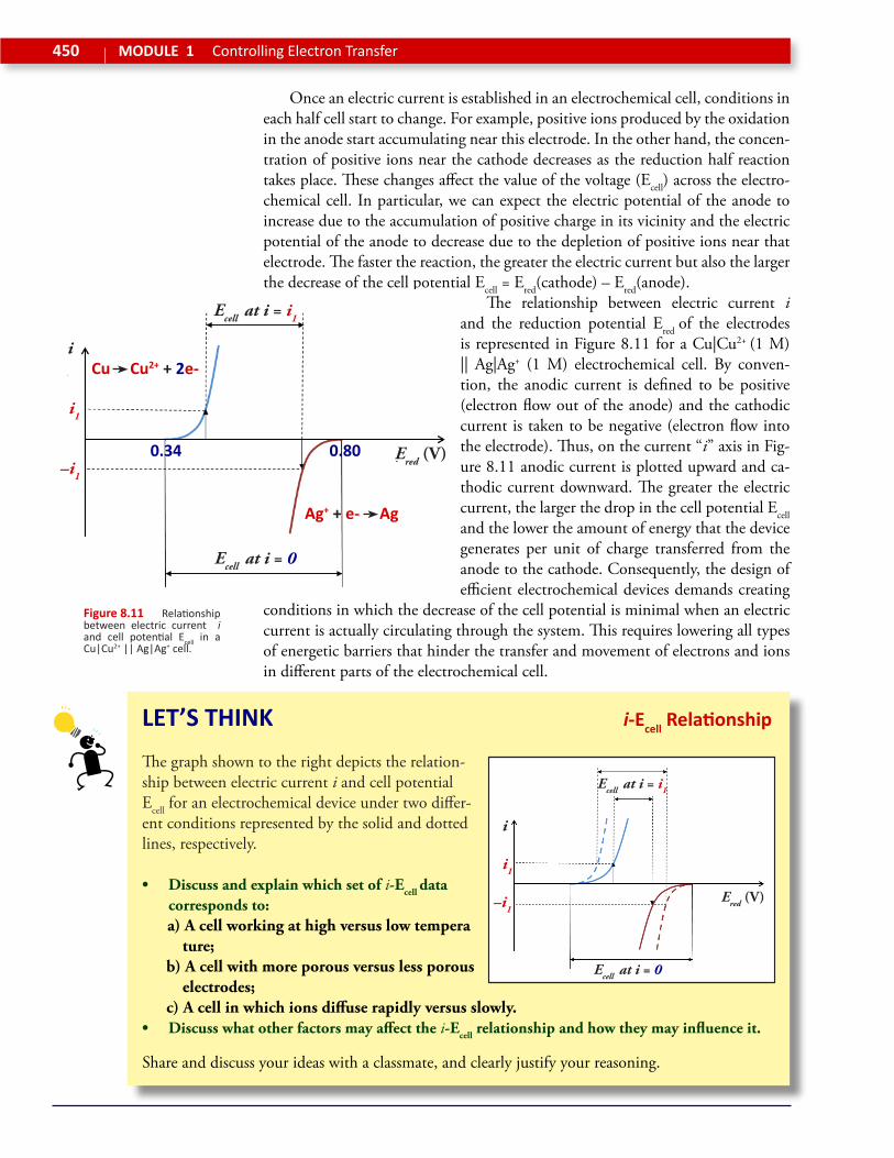
Once an electric current is established in an electrochemical cell, conditions in each half cell start to change. For example, positive ions produced by the oxidation in the anode start accumulating near this electrode. In the other hand, the concen-tration of positive ions near the cathode decreases as the reduction half reaction takes place. These changes affect the value of the voltage (Ecell) across the electro-chemical cell. In particular, we can expect the electric potential of the anode to increase due to the accumulation of positive charge in its vicinity and the electric potential of the anode to decrease due to the depletion of positive ions near that electrode. The faster the reaction, the greater the electric current but also the larger the decrease of the cell potential Ecell = Ered(cathode) – Ered(anode).
The relationship between electric current i and the reduction potential Ered of the electrodes is represented in Figure 8.11 for a Cu|Cu2+ (1 M) || Ag|Ag+ (1 M) electrochemical cell. By conven-tion, the anodic current is defined to be positive (electron flow out of the anode) and the cathodic current is taken to be negative (electron flow into the electrode). Thus, on the current “i” axis in Fig-ure 8.11 anodic current is plotted upward and ca-thodic current downward. The greater the electric current, the larger the drop in the cell potential Ecell and the lower the amount of energy that the device generates per unit of charge transferred from the anode to the cathode. Consequently, the design of efficient electrochemical devices demands creating
conditions in which the decrease of the cell potential is minimal when an electric current is actually circulating through the system. This requires lowering all types of energetic barriers that hinder the transfer and movement of electrons and ions in different parts of the electrochemical cell.
Figure 8.11 Relationship between electric current i and cell potential Ecell in a Cu|Cu2+ || Ag|Ag+ cell.
LET’S THINK i-Ecell Relationship
The graph shown to the right depicts the relation-ship between electric current i and cell potential Ecell for an electrochemical device under two differ-ent conditions represented by the solid and dotted lines, respectively.
• Discuss and explain which set of i-Ecell data corresponds to:
a) A cell working at high versus low tempera ture; b) A cell with more porous versus less porous electrodes; c) A cell in which ions diffuse rapidly versus slowly.• Discuss what other factors may affect the i-Ecell relationship and how they may influence it.
Share and discuss your ideas with a classmate, and clearly justify your reasoning.
i
i1
–i1
Ered (V)
Ecell at i = 0
Ecell at i = i1
0.34 0.80
Cu Cu2+ + 2e-
Ag+ + e- Ag
i
i1
–i1
Ecell at i = 0
Ecell at i = i1
Ered (V)

451U8 How do we harness chemical energy?Chemical Thinking
FACING THE CHALLENGE Bio-Batteries
A bio-battery is an electrochemical device that gen-erates electricity from organic compounds, such as sucrose, glucose, and fructose. The batteries rely on biocatalysts to increase rates of oxidation and facilitate electron transfer. The biocatalysts can be enzymes or microorganisms that help process the organic fuels. In passive bio-batteries, the reactive substances are absorbed into the system by natural diffusion. In active devices, the reactants are in-jected into the electrochemical cell. In the future, miniature bio-batteries could be used to power microsensors implanted within a human patient to monitor blood pres-sure, temperature, and the concentration of different metabolites.
The chemical reac-tions in a bio-battery can proceed by direct electron transfer be-tween the biocatalysts (enzymes) and the elec-trodes. However, it is common to use “me-diators” that reduce the kinetic barrier for electron transfer. Many of these mediators are vitamin molecules, such as vitamin C and vitamin K3. Direct transfer systems are more desirable as they simplify the construction of the batteries.
A bio-battery typically includes an anode containing the carbohydrate to be oxidized, car-bohydrate-digesting enzymes, and a mediator. The cathode contains oxygen, oxygen-reducing enzymes, and a mediator. The two half cells are divided by a porous separator. When using glucose as a fuel, the oxidation at the anode can be repre-sented as follows:
Glucose Glucanolactone + 2 H+ + 2 e–
Hydrogen ions H+ migrate to the cathode through the porous separator, where they participate in the reduction reaction
O2 + 4 H+ + 4 e– 2 H2O
Due to the selective reactivity of the enzymes at each electrode, no cross reaction occurs between the anode and the cathode.
Currently, the are no bio-battery templates that allow the mass production of miniature devic-es with a size in the order of 1 cubic centimeter, as needed for physiological sensors. Electron flow in current devices is too slow, mostly due to the diffi-
culty of establishing ef-fective contact between enzymes and electrodes. Enzyme stability is also a critical issue as these bio-catalysts are very sensitive to changes in temperature and pH.
Enzymes used in bio-batteries are ex-tracted from micro-organisms an immo-bilized onto carbon nanotubes that are used as electrodes. Nano-materials provide large surface areas for the
attachment of enzymes, increasing the concentra-tion of biocatalyst and improving battery power density. Additionally, nanostructured materials ex-hibit great potential for stabilizing enzyme activity. Carbon nanotubes, however, seem to induce the denaturation of some proteins by dehydration.
An important advantage of bio-batteries over other types of electrochemical devices is the pos-sibility of instant recharge. If the organic fuel is readily available in the surroundings, these batter-ies can continuously refuel. They are also a clean and renewable energy source fueled by inexpen-sive materials, including different types of waste. Unfortunately, existing prototypes are not yet competitive in terms of energy storage and power density.
Anode
Electrolyte
CathodeSeparator
H+
Glucose Glucanolactone
O2 H2O
Anode EnzymesAnode
Mediators
Cathode MediatorsCathode Enzymes
e–

452 MODULE 1 Controlling Electron Transfer
Hydrogen Fuel CellFuel cells are electrochemical devices in which reactants are con-tinuously supplied to the system to sustain the redox reaction. In a hydrogen fuel cell, for example, hydrogen gas and oxygen gas from air are used to produce energy. The overall reaction that takes place in the hydrogen fuel cell can be represented as: H2(g) + 1/2 O2(g) H2O(l).
ASSE
SS W
HAT
YOU
KN
OW
Let’s Apply
Thermodynamic Analysis
The table to the right lists relevant thermody-namic information for reactants and products in a hydrogen fuel cell.
• Qualitatively predict the signs of DHrxn and DSrxn for the overall reaction in a hydrogen fuel cell. Predict the effect of changing temperature T on the extent of the reaction.
• Verify your predictions using thermodynamic data to calculate DHorxn and DSo
rxn.
• Calculate the DGorxn and 25 oC and 70 oC (typical temperature at which a hydrogen fuel
cell operates). Build a graph showing how DGorxn changes as a function of T.
According to Equation (8.1): DGorxn = – nFEo
cell, where Eocell is the cell potential generated by a
fuel cell at standard pressures (1 atm).
• Estimate the value of Eocell at 25 oC and 70 oC. Build a plausible explanation for the
change of Eocell with temperature.
Share and discuss your ideas with a classmate, and clearly justify your reasoning.
Oxidation-Reduction
Consider the overall chemical reaction in a hydrogen fuel cell: H2(g) + 1/2 O2(g) H2O(l)
• Determine the oxidation state of each atom in the reactants and products.
• Identify the oxidized and reduced atoms in the process.
• Identify the oxidizing agent and reducing agent in the reaction.
• Determine the number of electrons exchanged per molecule of H2 consumed.
Share and discuss your ideas with a classmate, and clearly justify your reasoning.
DHof (kJ/mol) So
f (J/(mol K)
H2(g) 0 130.6
O2(g) 0 205.0
H2O(l) –285.8 69.95
By Dervisoglu (Ow
n work)
[Public Domain] via W
ikimedia Com
mons

453U8 How do we harness chemical energy?Chemical Thinking
ASSESS WHAT YO
U KN
OW
Cell Potential and Energy Output
The table to the right lists the standard reduc-tion potentials for redox pairs relevant to the operation of fuel cells under acidic or basic (al-kaline) conditions.
• Express the half reactions taking place in the anode and the cathode of hydrogen fuel cell working under acidic conditions.
• Express the half reactions taking place in the anode and the cathode of hydrogen fuel cell working under basic (alkaline) conditions.
• Determine Eocell for each of these fuel cells and compare your result with the value
obtained using the DGorxn from thermodynamic data.
• Estimate the maximum amount of energy that each of these fuels cell produces per mol of hydrogen consumed under standard conditions.
• Express the Nernst equation for these fuel cells in terms of the temperature of the system and the pressure of the gases used as reactants. Qualitatively analyze this rela-tionship and determine the best conditions to maximize energy output.
Share and discuss your ideas with a classmate, and clearly justify your reasoning.
Fuel Cell Kinetics
Given that reactants are in the gas phase in hydrogen fuel cells, inert metal electrodes are used as surfaces where electron transfer takes place. The nature of the electrodes used af-fects the relationship between the electric current i established in the system and the cell potential Ecell of the device.
The graph to the right represents i-Ecell data for hydrogen fuel cells with two different types of electrodes.
• Which type of electrode would be best to use?
• When a current is established, the change in Ered is greater in the cathode than in the anode. Propose a plausible explanation for this result.
• How would you expect temperature to affect the value of Ecell when an electric cur-rent flows through the fuel cell?
Share and discuss your ideas with a classmate, and clearly justify your reasoning.
Standard Reduction Potentials
Reduction Half-Reaction Eored (V)
O2 + 4 H+ + 4 e- 2 H2O +1.23
O2 + 2 H2O + 4 e- 4 OH– +0.40
2 H+ + 2 e- H2 0
2 H2O + 2 e- H2 + 2 OH– –0.83
i
i1
–i1
Ered (V)
Pt Au
PtAu
0.0 1.23
454 MODULE 1 Controlling Electron Transfer
ASSE
SS W
HAT
YOU
KN
OW
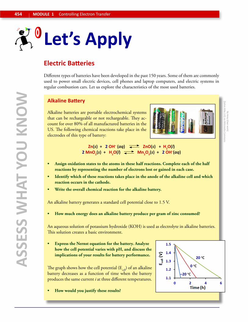
Let’s ApplyElectric BatteriesDifferent types of batteries have been developed in the past 150 years. Some of them are commonly used to power small electric devices, cell phones and laptop computers, and electric systems in regular combustion cars. Let us explore the characteristics of the most used batteries.
Alkaline Battery
Alkaline batteries are portable electrochemical systems that can be rechargeable or not rechargeable. They ac-count for over 80% of all manufactured batteries in the US. The following chemical reactions take place in the electrodes of this type of battery:
Zn(s) + 2 OH– (aq) ZnO(s) + H2O(l)2 MnO2(s) + H2O(l) Mn2O3(s) + 2 OH–(aq)
• Assign oxidation states to the atoms in these half reactions. Complete each of the half reactions by representing the number of electrons lost or gained in each case.
• Identify which of these reactions takes place in the anode of the alkaline cell and which reaction occurs in the cathode.
• Write the overall chemical reaction for the alkaline battery.
An alkaline battery generates a standard cell potential close to 1.5 V.
• How much energy does an alkaline battery produce per gram of zinc consumed?
An aqueous solution of potassium hydroxide (KOH) is used as electrolyte in alkaline batteries. This solution creates a basic environment.
• Express the Nernst equation for the battery. Analyze how the cell potential varies with pH, and discuss the implications of your results for battery performance.
The graph shows how the cell potential (Ecell) of an alkaline battery decreases as a function of time when the battery produces the same current i at three different temperatures.
• How would you justify these results?
By Aney (Ow
n work)
[Sahre Alike 3.0] via Wikim
edia Comm
ons
–20 oC
0 oC
20 oC

455U8 How do we harness chemical energy?Chemical Thinking
ASSESS WHAT YO
U KN
OW
Lead-Acid Battery
The lead–acid battery was developed more than 150 years ago. It is a low cost rechargeable battery that provides the high current required by automobile starter motors. Lead–acid battery sales ac-count for over 40% of the value from batteries sold worldwide. The following chemical reactions take place in the electrodes of this type of battery:
PbO2(s) + 3 H+(aq) + HSO4–(aq) PbSO4(s) + 2 H2O(l)
Pb(s) + HSO4–(aq) PbSO4(s) + H+(aq)
• Assign oxidation states to each atom in these half reactions. Complete each of the half reactions by representing the number of electrons lost or gained in each case.
• Identify which of these reactions takes place in the anode of the lead–acid battery and which reaction occurs in the cathode.
• Draw a schematic diagram of a lead–acid battery showing the chemical composition and structure of each half cell, as well as the flow of electric charge throughout the system.
The standard reduction potentials in the cathode and anode of a lead–acid battery are Eo
red = 1.685 V and Eored = –0.356 V, respectively.
• Calculate the standard cell potential for this battery.
A typical car battery does not run under standard conditions. The concentration of sulfuric acid (H2SO4; a strong acid that completely dissociates into HSO4
– ions in aqueous solu-tion) is close to 5 M and the pH is close to 0.
• Write the overall chemical reaction for the alkaline battery.
• Express the Nernst equation for a lead–acid battery and calculate its actual cell po-tential.
• Express the Nernst equation for the battery as a function of pH. Make a graph of cell potential versus pH and discuss its implications for cell voltage and power.
The graph sketches how the reduction potentials of the cathode and the anode in a lead–acid battery change when a given current i is established across the battery at two different temperatures.
• Explain why starting a car is more difficult under cold weather conditions.
i
i1
–i1Ered (V)
–10 oC10 oC

456 MODULE 1 Controlling Electron Transfer
ASSE
SS W
HAT
YOU
KN
OW
Let’s ApplyLithium-Ion Battery
Lithium-ion batteries are often used in con-sumer electronics. They are one of the most popular types of rechargeable batteries for portable devices, such as watches, cell phones, and laptop computers. This type of battery takes advantage of the ability of Li+ ions to be reversibly inserted and removed from cer-tain solids. The image represents the internal structure of this type of battery.
The half cell reactions in the lithium-ion battery are:
ANODE: LixC6 x Li+ + x e- + C6 CATHODE: Li1-xCoO2 + x Li+ + x e- LiCoO2
where LixC6 represents graphite (C6) intercalated with x moles of Li+ ions, and LiCoO2 repre-sents lithium cobalt (III) oxide. When x moles of Co3+ ions are oxidized to Co4+, x moles of Li+
ions are released from the solid and Li1-xCoO2 is produced. This process is reversible for x < 0.5.
• Analyze the information provided and generate a detailed explanation of how the lithi-um-ion battery works. Discuss what happens in each half cell as electrons are transferred from the anode to the cathode, and Li+ diffuse between the two cells.
• A lithium-ion battery can be recharged. Discuss why this is possible and how it can be done. Analyze the distribution and movement of Li+ ions between the two half cells when the battery is charging and when it is discharging.
A lithium-ion battery generates a standard cell poten-tial close to 3.7 V. As shown in the graph, this volt-age depends on temperature and the value of the elec-tric current i (measure din milliampere, mA) flowing through the system.
• Analyze the data represented in the graph and build a kinetic argument to justify the behavior of the lithium-ion battery under different condi-tions.
Anode Cathode
LixC6 Li1-xCoO2
Li+
0.2 mA
2.0 mA
20 mA

457U8 How do we harness chemical energy?Chemical Thinking
Unit 8: Image AttributionsModule 1Most of the images in this module have been generated by the authors (Own work). Other attributions include, P436 & P437: Background “Berlin Potdamer Platz” by Avda (Own work) [Share Alike 3.0] http://commons.wikimedia.org/wiki/File:Berlin_-_Potsdamer_Platz_-_E-Mo-bility-Charging.jpg; P438: Upper right “Lithium Battery CR2032” by KyloDee (Own work) [Public Domain] http://commons.wikimedia.org/wiki/File:Battery-lithium-cr2032.jpg; P443: Middle right by Toby Hudson (Own work) [Share Alike 3.0] http://commons.wikimedia.org/wiki/File:Precipitation_of_Silver_on_Copper_1.jpg; P445: Middle right by Shamsher Singh (Own wok) http://chemwiki.ucdavis.edu/Analyti-cal_Chemistry/Electrochemistry/Voltaic_Cells; P452: Upper right by Dervisoglu (Own work) [Public domain] http://commons.wikimedia.org/wiki/File:Solid_oxide_fuel_cell_protonic.svg; P454: Upper right “Alkaline batteries” by Aney (Own work) [Share Alike 3.0] http://commons.wikimedia.org/wiki/File:Alkali_battery_5.jpg
GeneralActivity icons: Clip art from Microsoft Office; Molecular structures: Derived from online public software (Chemical Education Digital Library, Jmol) and via Wikimedia Commons (Public domain images).