Embed Size (px)
Citation preview
In Search of a Better MEMS Switch How nanostructured dielectrics soften
landing, increase travel Range, and reduce Energy dissipation
Muhammad A. Alam
Ankit Jain, and Sambit Palit [email protected]
Landau
2
copyright 2012
This material is copyrighted by M. A. Alam under the following Creative Commons license. Conditions for using these materials is described at http://creativecommons.org/licenses/by-nc-sa/2.5/
3
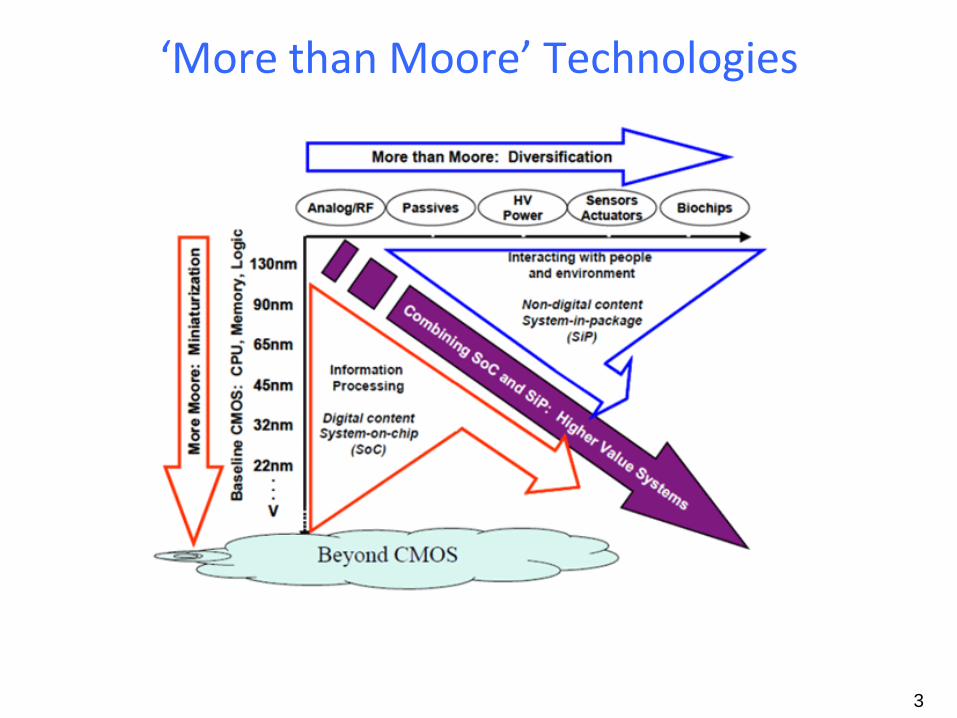
‘More than Moore’ Technologies
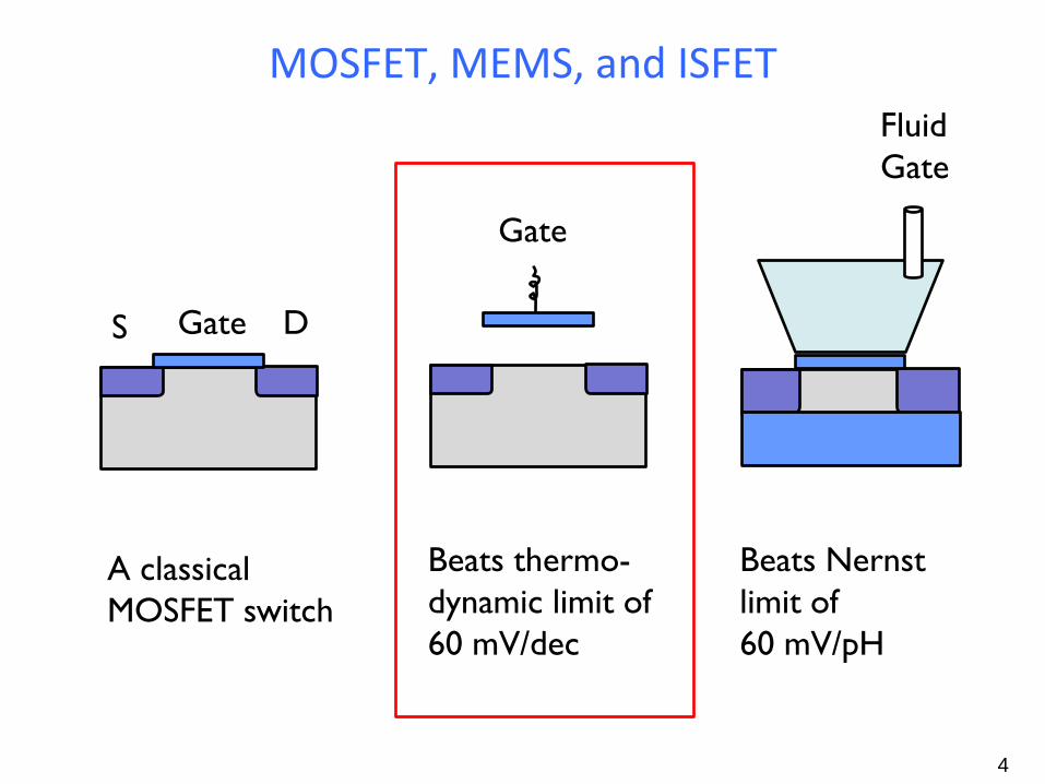
MOSFET, MEMS, and ISFET
4
Gate S D
Gate
Fluid Gate
Beats thermo- dynamic limit of 60 mV/dec
Beats Nernst limit of 60 mV/pH
A classical MOSFET switch
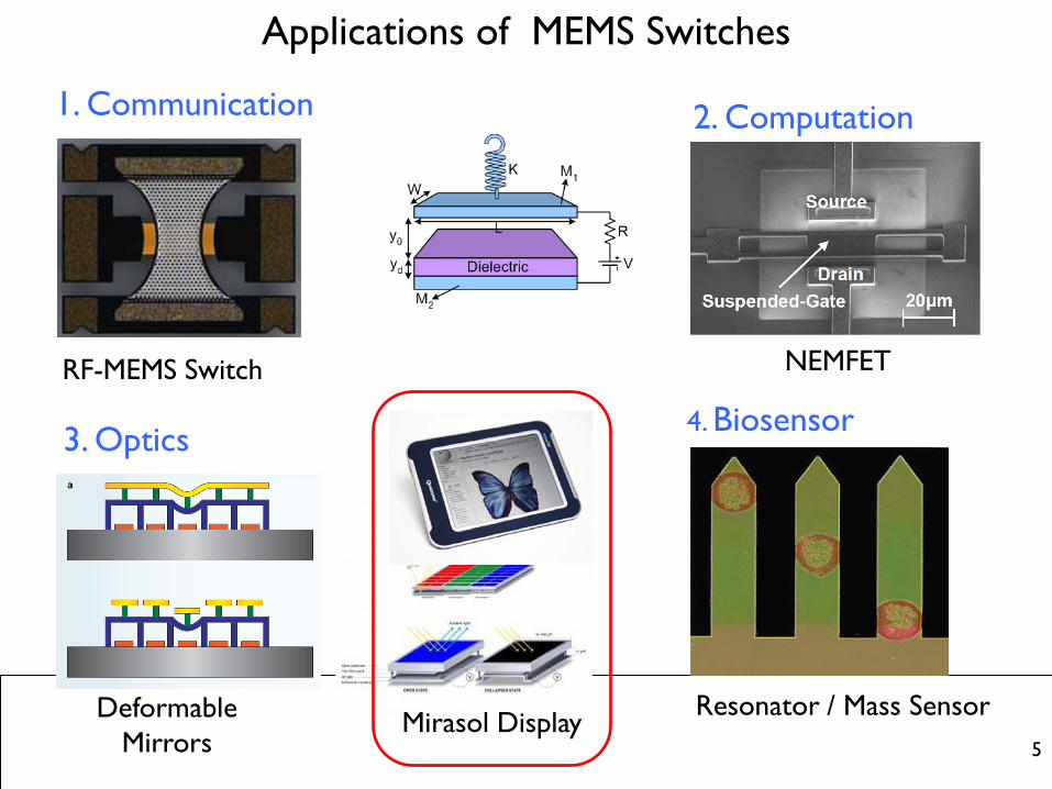
Applications of MEMS Switches
5
1. Communication
RF-MEMS Switch
2. Computation
NEMFET
4. Biosensor
Resonator / Mass Sensor
3. Optics
Deformable Mirrors
Mirasol Display
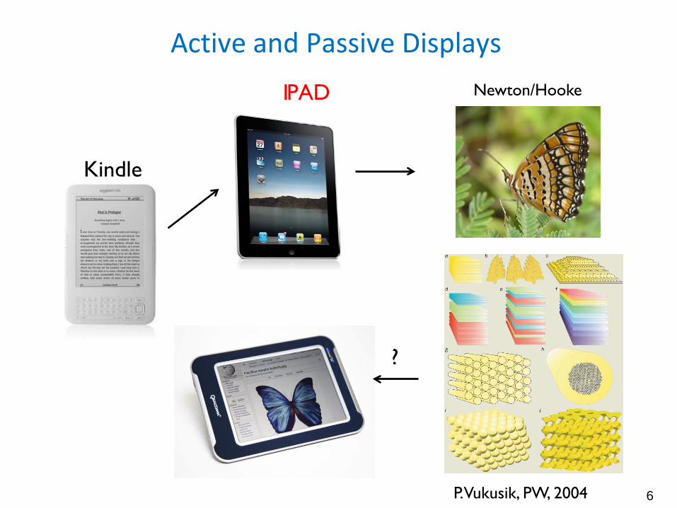
Active and Passive Displays
6
Kindle
IPAD Newton/Hooke
P. Vukusik, PW, 2004
?
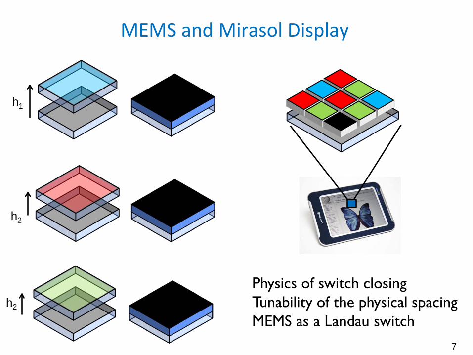
MEMS and Mirasol Display
7
h1
h2
h2
Physics of switch closing Tunability of the physical spacing MEMS as a Landau switch
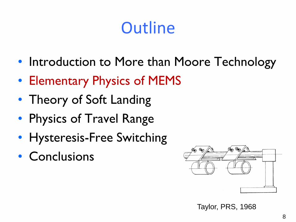
Outline
• Introduction to More than Moore Technology • Elementary Physics of MEMS • Theory of Soft Landing • Physics of Travel Range • Hysteresis-Free Switching • Conclusions
8 Taylor, PRS, 1968
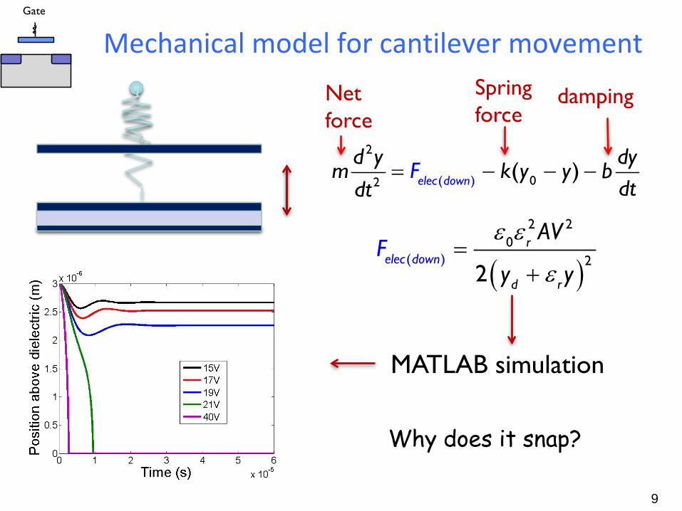
Mechanical model for cantilever movement
9
= − − −2
( 02 ) ( )elec down
d y dym k y y b
dtF
dt
damping Spring force
Net force
MATLAB simulation
( )ε ε
ε=
+(
2 20
2)2
relec dow
r
n
d
AV
y yF
Why does it snap?
Gate
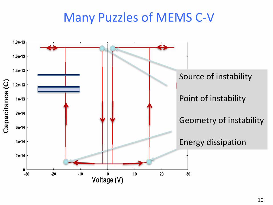
Many Puzzles of MEMS C-V
Pull-In
Pull-Out
10
Source of instability Point of instability Geometry of instability Energy dissipation
y y0
Fs, FE
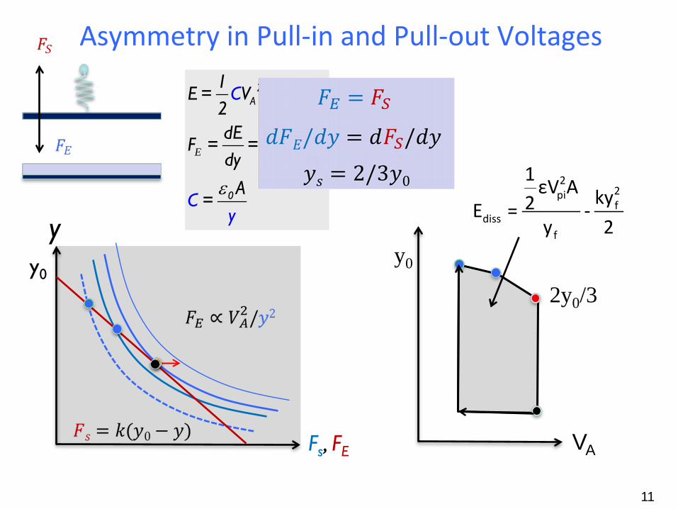
Asymmetry in Pull-in and Pull-out Voltages
11
E
ε
2A
2A
0
1E = V
2dE 1
F = =
C
dCdy
Vy
C
d 2A
=y
2y0/3
y0
VA
22pif
dissf
1 εV A ky2E = -y 2
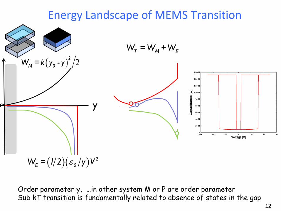
Energy Landscape of MEMS Transition
12
Order parameter y, …in other system M or P are order parameter Sub kT transition is fundamentally related to absence of states in the gap
MW = W +WT E
y
( ) 22M 0W = k y - y
( )( ) 2E 0W = 1 2 y Vε
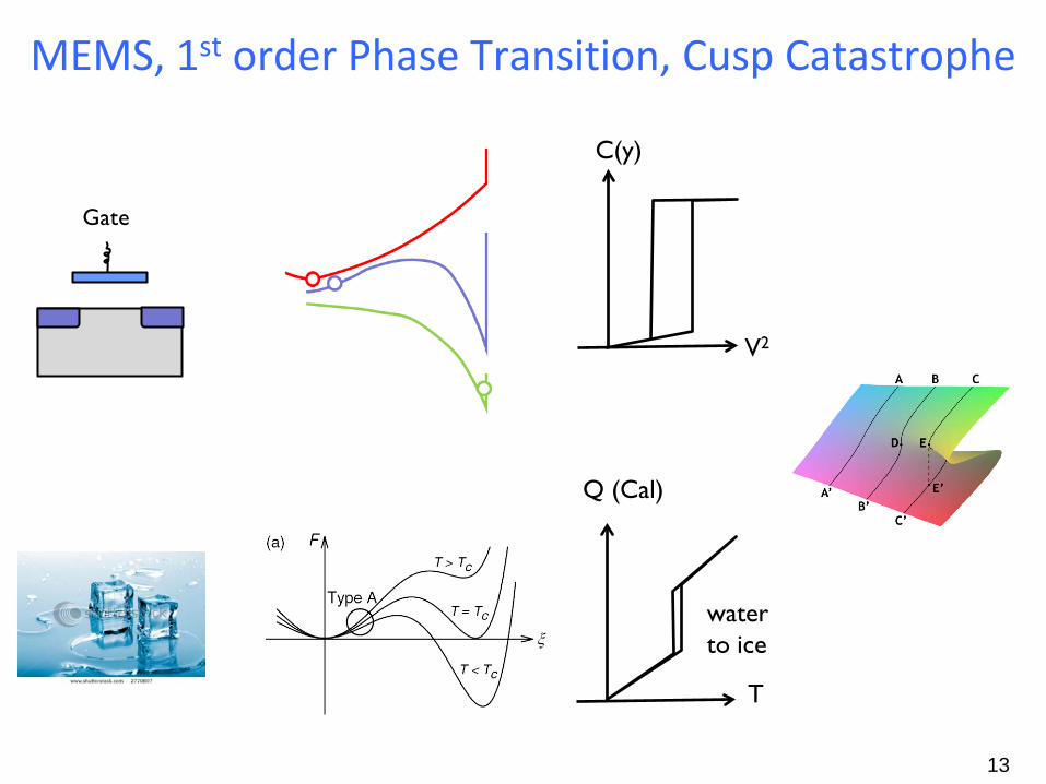
MEMS, 1st order Phase Transition, Cusp Catastrophe
13
Q (Cal)
T
water to ice
Gate
V2
C(y)
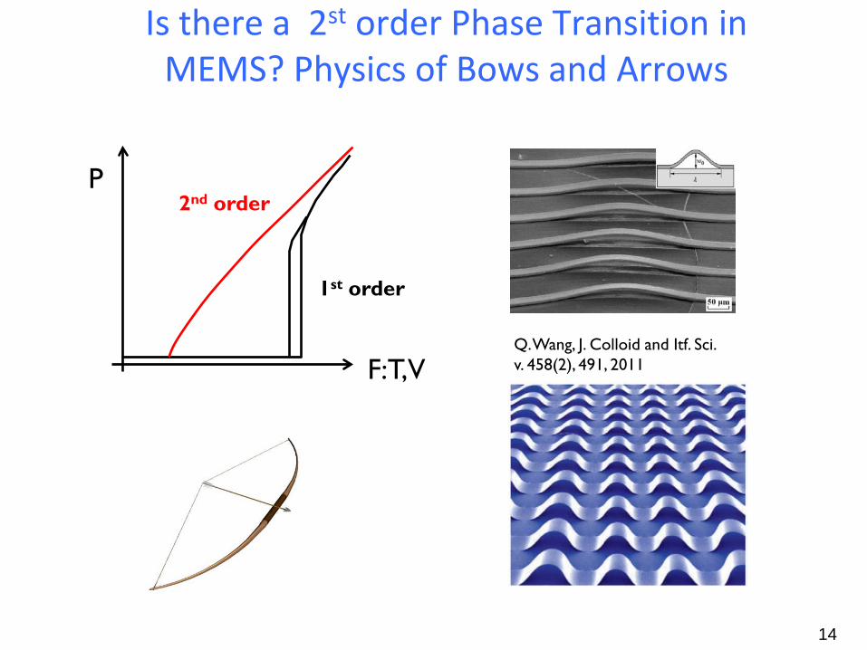
Is there a 2st order Phase Transition in MEMS? Physics of Bows and Arrows
14
Q. Wang, J. Colloid and Itf. Sci. v. 458(2), 491, 2011
P
F:T,V
1st order
2nd order
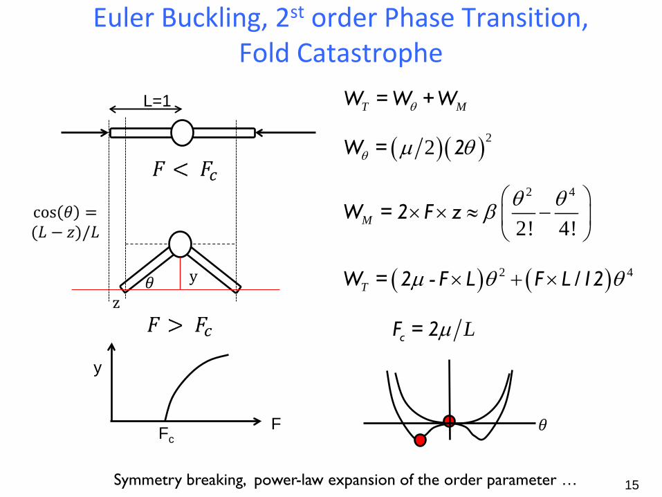
Euler Buckling, 2st order Phase Transition, Fold Catastrophe
15
y
T MθW = W +W
( )( )22θ µ θW = 2
2 4
2! 4!Mθ θβ
× × ≈ −
W = 2 F z
z
L=1
( ) ( )2 4T µ θ θ× + ×W = 2 - F L F L /12
LµcF = 2
y
F Fc
Symmetry breaking, power-law expansion of the order parameter …

Outline
• Introduction to More than Moore Technology • Elementary Physics of MEMS • Theory of Soft Landing • Physics of Travel Range • Hysteresis-Free Switching • Conclusions
16
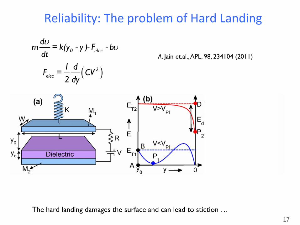
Reliability: The problem of Hard Landing
17
0
dm = k(y - y )- F - b
dtυ υelec
( )2elec
1 dF = CV
2 dy
The hard landing damages the surface and can lead to stiction …
A. Jain et.al., APL, 98, 234104 (2011)
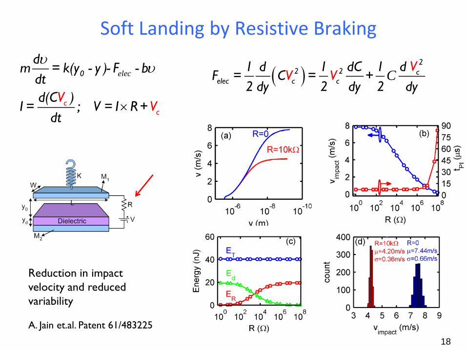
Soft Landing by Resistive Braking
18
elecυ υ
×
0
cc
dm = k(y - y )- F - b
dtd(C )
I = ; V = I R+dtV
V
( )2
2 2 celec c c
VV V
d 1 d 1 dC 1F = C = +
2 dy 2 dy 2 dyC
Reduction in impact velocity and reduced variability
A. Jain et.al. Patent 61/483225
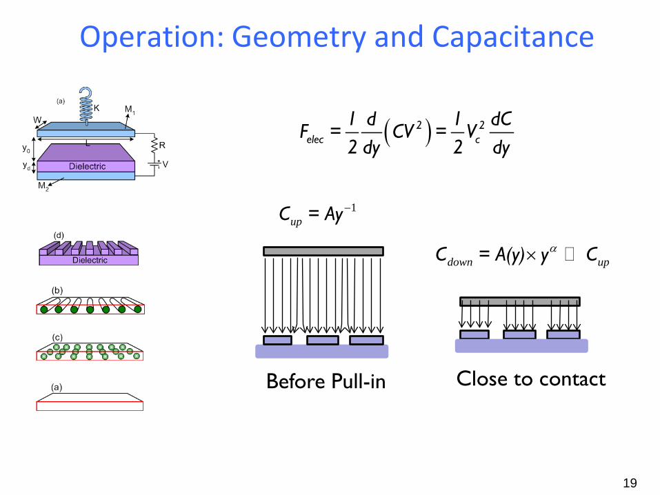
Operation: Geometry and Capacitance
19
( )2 2elec c
1 d 1 dCF = CV = V
2 dy 2 dy
1C = Ay−up
C = A(y) y Cα× down up
Before Pull-in Close to contact
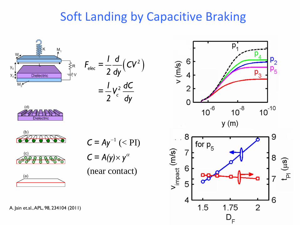
Soft Landing by Capacitive Braking
20
( )2elec
2c
1 dF = CV
2 dy1 dC
= V2 dy
1 (< PI)
(near contact)
C = Ay
C = A(y) yα
−
×
A. Jain et.al., APL, 98, 234104 (2011)
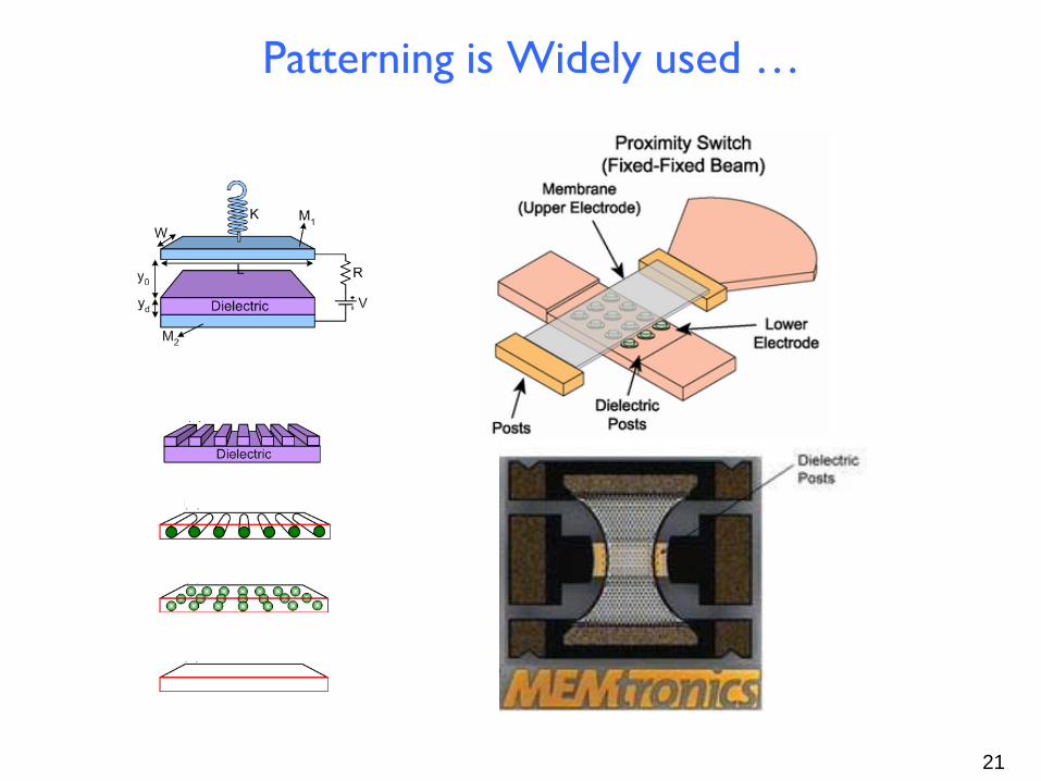
Patterning is Widely used …
21
Outline
• Introduction to More than Moore Technology • Elementary Physics of MEMs • Theory of Soft Landing • Physics of Travel Range • Hysteresis-Free Switching • Conclusions
22
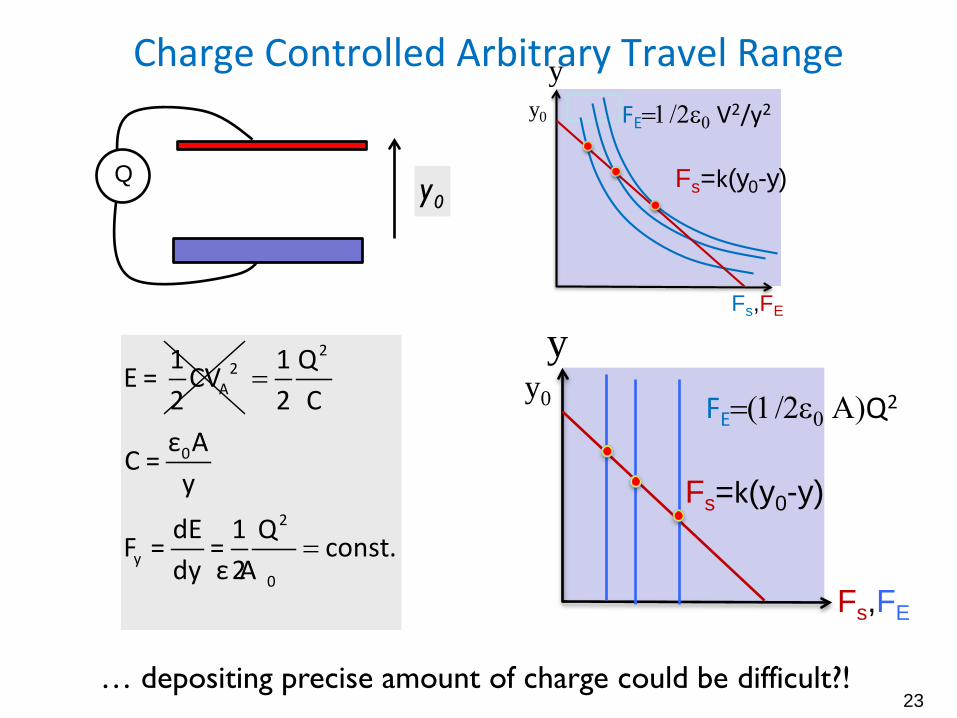
Charge Controlled Arbitrary Travel Range
23
0y
… depositing precise amount of charge could be difficult?!
Q
2A
1E = CV2
=
=
2
0
2
y0
1 Q2 C
ε AC =
ydE 1 QF = = const.dy 2ε A
y y0
Fs,FE
Fs=k(y0-y)
FE=(1/2ε0 Α)Q2
yy0
Fs,FE
Fs=k(y0-y)
FE=1/2ε0 V2/y2
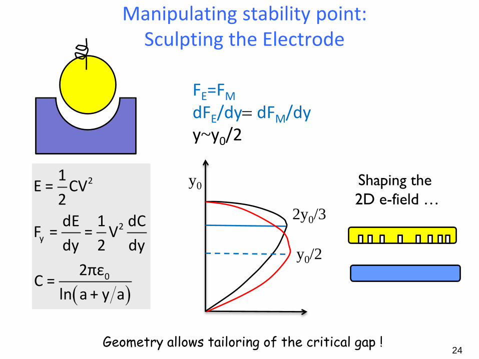
Manipulating stability point: Sculpting the Electrode
24
FE=FM dFE/dy= dFM/dy y~y0/2
y0
( )
2
2y
0
1E = CV
2dE 1 dC
F = = Vdy 2 dy
2πεC =
ln a + y a
2y0/3
Shaping the 2D e-field …
y0/2
Geometry allows tailoring of the critical gap !
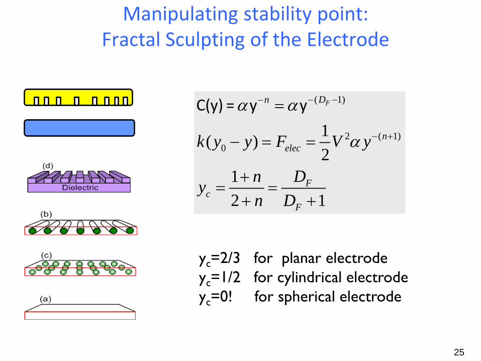
Manipulating stability point: Fractal Sculpting of the Electrode
25
( 1)
2 ( 1)0
1( )2
12 1
α α
α
− −−
− +
=
− = =
+= =
+ +
FDn
nelec
Fc
F
k y y F V y
Dnyn D
C(y) = y y
yc=2/3 for planar electrode yc=1/2 for cylindrical electrode yc=0! for spherical electrode
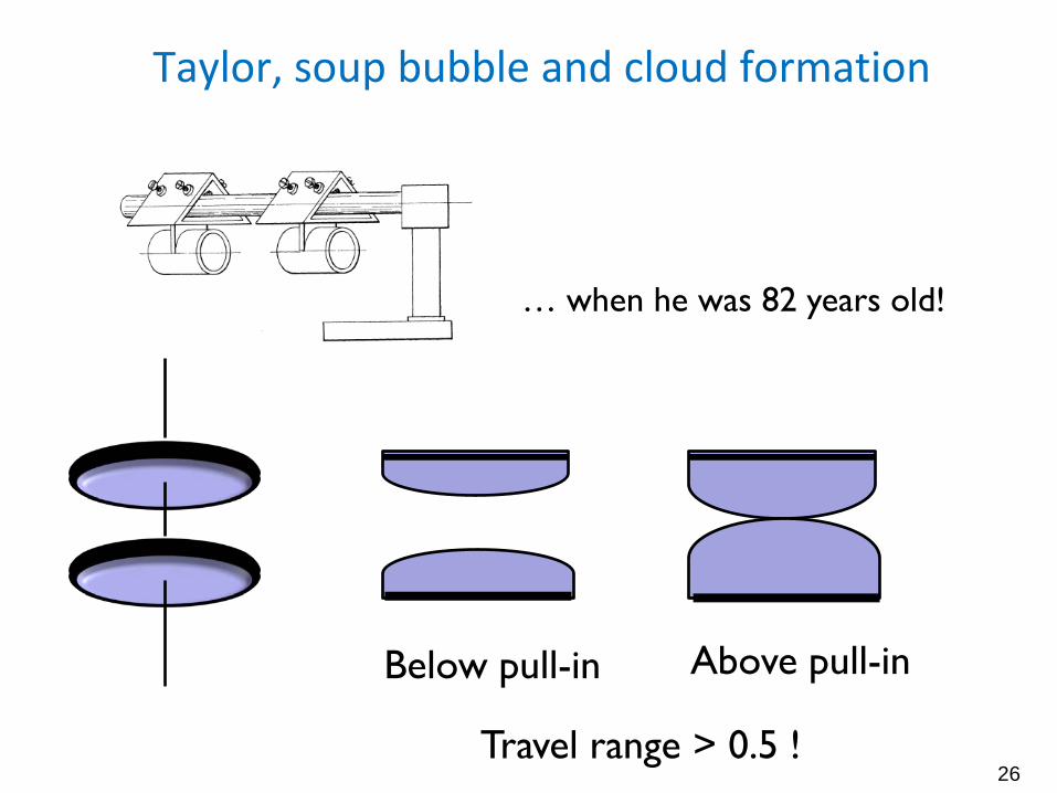
Taylor, soup bubble and cloud formation
26
Below pull-in Above pull-in
Travel range > 0.5 !
… when he was 82 years old!
Outline
• Introduction to More than Moore Technology • Elementary Physics of MEMs • Theory of Soft Landing • Physics of Travel Range • Hysteresis-Free Switching • Conclusions
27
?
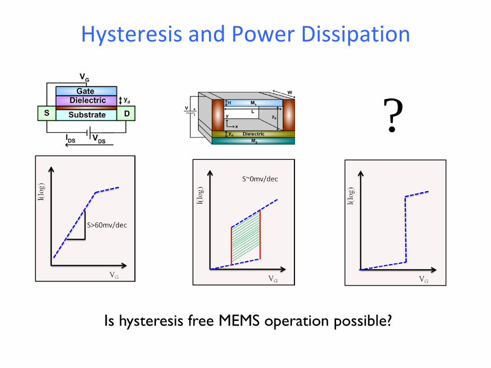
Hysteresis and Power Dissipation
Is hysteresis free MEMS operation possible?

yPOp
yPIn
yPOn yPIp -50 0 50-4000
-2000
0
2000
4000
6000
8000
x
U
4 2U cx ax= +
a− ↑
Origin of Hysteresis Loss
-100 -50 0 50 100-30
-20
-10
0
10
20
30
ε
x
0
-100 -50 0 50 100-40
-20
0
20
40
ε
x
-1
-100 -50 0 50 100-50
0
50
ε
x
-2
Landau theory suggests optimum landscape ..
100 101 102 1030
5
10
15
20
G/R
V (V
)
VPIVPO
yPOp
yPIn
yPOn yPIp
yPOp
yPIn
yPOn yPIp
yPIn =yPOp
yPIp=yPOn
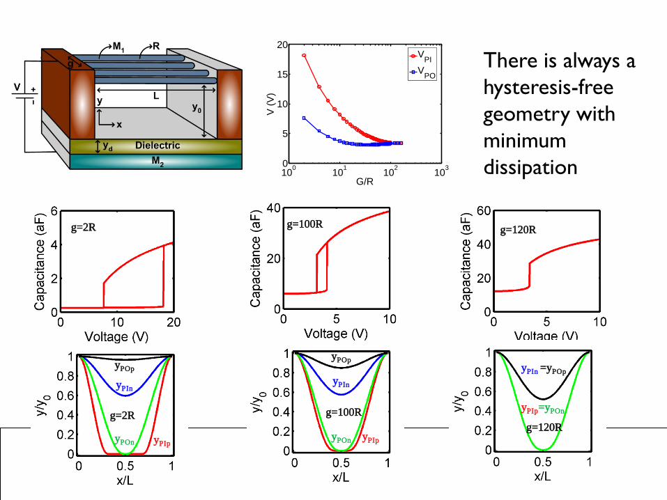
g=2R g=100R g=120R
g=2R g=100R g=120R
There is always a hysteresis-free geometry with minimum dissipation
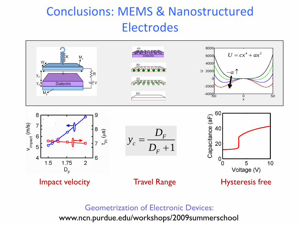
Conclusions: MEMS & Nanostructured Electrodes
31
-50 0 50-4000
-2000
0
2000
4000
6000
8000
x
U
4 2U cx ax= +
a− ↑
1F
cF
DyD
=+
Impact velocity Travel Range Hysteresis free
Geometrization of Electronic Devices: www.ncn.purdue.edu/workshops/2009summerschool
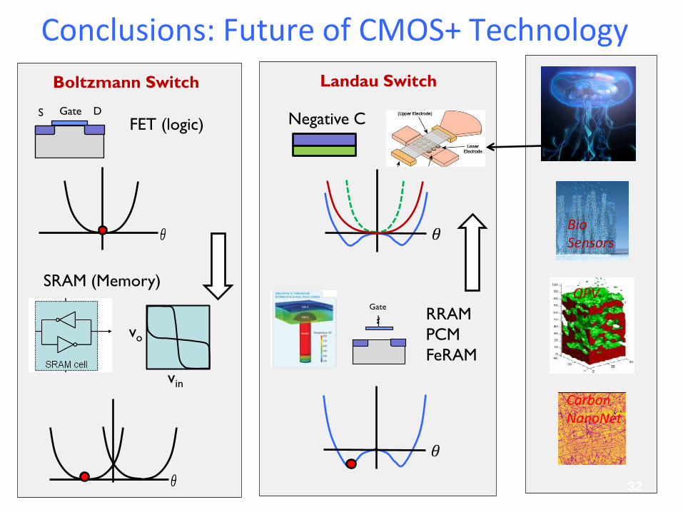
Conclusions: Future of CMOS+ Technology
32
Bio Sensors
Carbon NanoNet
OPV
GateS DFET (logic) Negative C
RRAM PCM FeRAM
Gate
SRAM (Memory)
vin
vo
Boltzmann Switch Landau Switch
References • H. Torun, APL, 91, 253113, 2007. Spring constant tuning of active atomic force
microscope. G. Taylor, The coalescence of closely space drops" Proc. Roy. Soc. A, 306, 423, 1968. As a model for spherical electrodes in the MEMs configuration. http://www.memtronics.com/page.aspx?page_id=15 (Goldsmith dimpled structure) http://www.memtronics.com/files /Understanding%20and%20Improving%20Longevity%20in%20RF%20MEMS%20SPIE%206884-1.pdf http://www.google.com/patents?hl=en&lr=&vid=USPATAPP11092462&id=BEeZAAAAEBAJ&oi=fnd&dq=muldavin+switch+dimpled&printsec=abstract#v=onepage&q&f=false (corrugated top electrode).
33