Embed Size (px)
Citation preview
External Use
TM
How to Use Functional Safety
Manual and Dynamic FMEDA to
Design Your Safe System
EUF-ACC-T1555
J U L Y . 2 0 1 5
Mathieu Blazy-Winning | Automotive MCU
TM
External Use 1
Agenda
• Functional Safety at Freescale
• Freescale Development Process for ISO 26262
• MCU Safety Context and Safety Concepts
• Standard Deliverables to Enable the Customer
− Safety Manual
− Dynamic FMEDA
TM
External Use 2
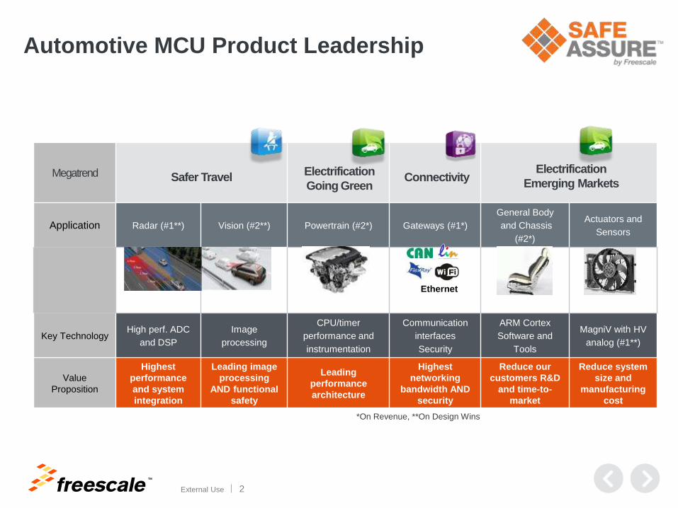
Automotive MCU Product Leadership
Megatrend
Application Radar (#1**) Vision (#2**) Powertrain (#2*) Gateways (#1*)
General Body
and Chassis
(#2*)
Actuators and
Sensors
Key TechnologyHigh perf. ADC
and DSP
Image
processing
CPU/timer
performance and
instrumentation
Communication
interfaces
Security
ARM Cortex
Software and
Tools
MagniV with HV
analog (#1**)
Value
Proposition
Highest
performance
and system
integration
Leading image
processing
AND functional
safety
Leading
performance
architecture
Highest
networking
bandwidth AND
security
Reduce our
customers R&D
and time-to-
market
Reduce system
size and
manufacturing
cost
Safer TravelElectrification
Emerging Markets
Ethernet
Electrification
Going GreenConnectivity
*On Revenue, **On Design Wins
TM
External Use 3
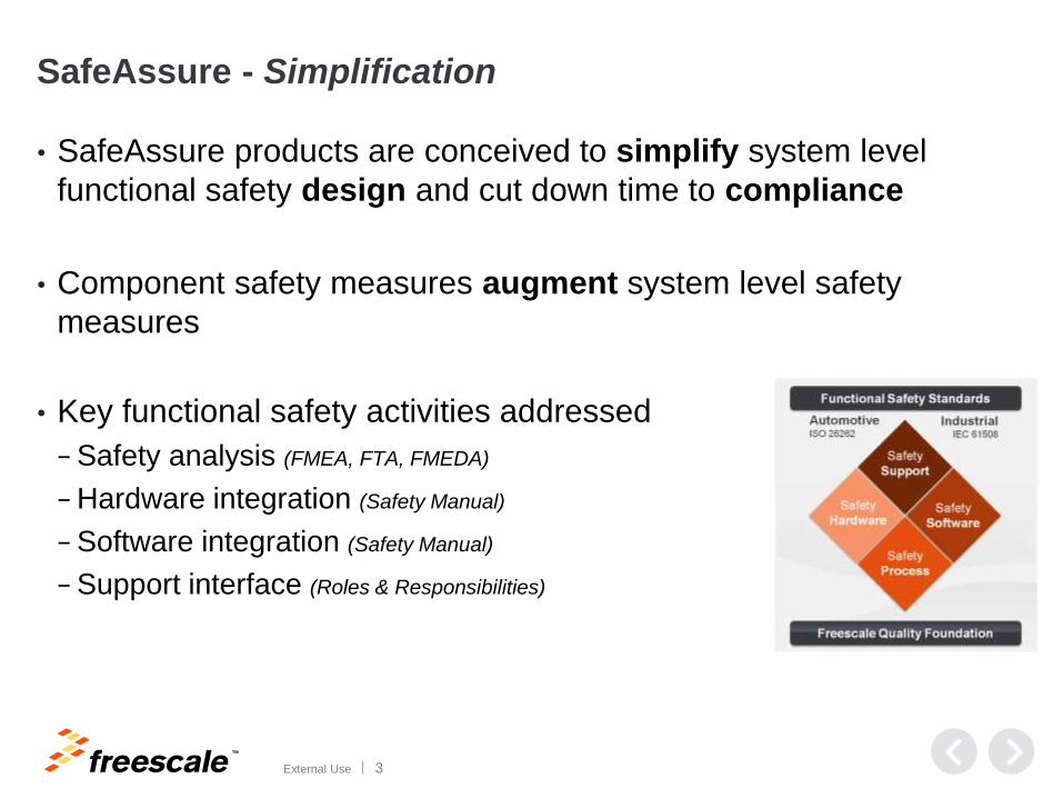
SafeAssure - Simplification
• SafeAssure products are conceived to simplify system level
functional safety design and cut down time to compliance
• Component safety measures augment system level safety
measures
• Key functional safety activities addressed
− Safety analysis (FMEA, FTA, FMEDA)
− Hardware integration (Safety Manual)
− Software integration (Safety Manual)
− Support interface (Roles & Responsibilities)
TM
External Use 4
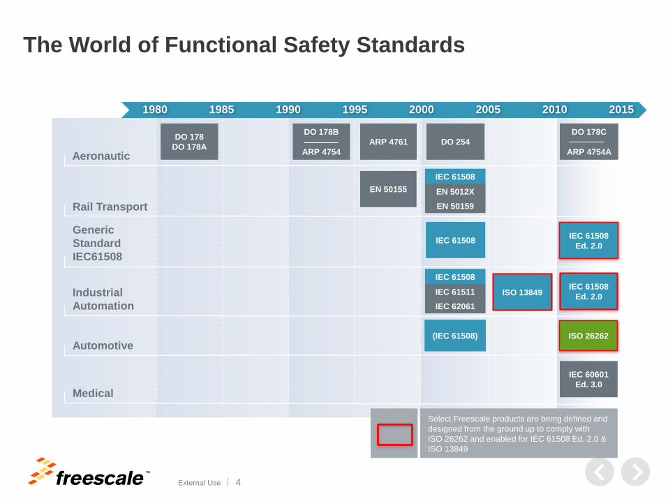
The World of Functional Safety Standards
Generic
Standard
IEC61508
Industrial
Automation
Rail Transport
Automotive
Aeronautic
1980 1985 1990 1995 2000 2005 2010 2015
ISO 26262
IEC 61508IEC 61508
Ed. 2.0
IEC 61508
Ed. 2.0
EN 50155
IEC 61508
EN 5012X
EN 50159
(IEC 61508)
DO 178
DO 178AARP 4761 DO 254
Medical
IEC 60601
Ed. 3.0
Select Freescale products are being defined and
designed from the ground up to comply with
ISO 26262 and enabled for IEC 61508 Ed. 2.0 &
ISO 13849
DO 178B
ARP 4754
DO 178C
ARP 4754A
IEC 61508
IEC 61511
IEC 62061
ISO 13849
TM
External Use 5
History of Auto MCU Functional Safety SolutionsG
en
1 S
afe
ty
Ge
n 2
Sa
fety
Ge
n 3
Sa
fety MPC5744P/MPC5777K/etc 55 nm
2000
2008
PowerSBC
MPC5643L – 90 nm
Custom Safety Platform for Braking
Fu
nctio
nal S
afe
ty S
olu
tions
PowerSBC
2012
• Voltage Supervision
• Fail-Safe State Machine
• Fail-Safe IO
• Advanced Watchdog
• Voltage Supervision
• Fail-Safe State Machine
• Fail-Safe IO
• Advanced Watchdog
• 32-bit Dual-Core MCU
• Developed according to ISO 26262
• Target Applications for Chassis – ASILD
• 32-bit Dual/Quad-Core MCU
• Developed according to ISO 26262
• Target Applications Chassis & P/T for – ASILD
•Safe methodology, Architecture, SW and tools
• Started to ship in 2000 first safe MCU for braking applications
• IEC 61508 / ISO 26262 compliance achieved at system level
(top down approach)
• MCU features are a key enabler for SIL3 / ASILD
Custom IC
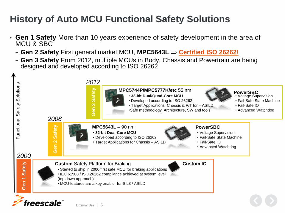
• Gen 1 Safety More than 10 years experience of safety development in the area of MCU & SBC
− Gen 2 Safety First general market MCU, MPC5643L Certified ISO 26262!
− Gen 3 Safety From 2012, multiple MCUs in Body, Chassis and Powertrain are being designed and developed according to ISO 26262
TM
External Use 6
Freescale Development Process
for ISO 26262
TM
External Use 7
Freescale Development Process for ISO 26262
• Freescale is committed to addressing the requirements of ISO 26262
• Freescale MPC564xL is the first MCU to achieve a formal certificate for ISO 26262 ASIL D,
as certified (Link) by exida in 2012.
• Selected products are developed as a Safety Element out of Context (SEooC) where
Functional Safety Management and Quality Management are integrated in the development
process
• ISO 26262 Deployment completed across Freescale during 2011 - 2014
− Functional Safety Management
− Development Processes
− Product Architecture
• Standard Process
− All safety activities and deliverables required by ISO 26262 are integrated in the Freescale Quality
Maturity System (QMS), used to plan and track ISO 26262 compliance per product development.
TM
External Use 8
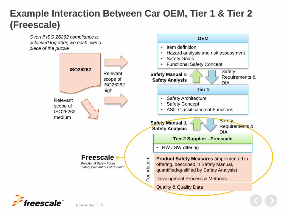
Example Interaction Between Car OEM, Tier 1 & Tier 2
(Freescale)
OEM
• Safety Architecture
• Safety Concept
• ASIL Classification of Functions
Tier 1
• HW / SW offering
Tier 2 Supplier - Freescale
• Item definition
• Hazard analysis and risk assessment
• Safety Goals
• Functional Safety ConceptISO26262 Safety
Requirements &
DIA
Safety
Requirements &
DIA
Safety Manual &
Safety Analysis
Relevant
scope of
ISO26262
high
Fo
un
datio
n Product Safety Measures (implemented in
offering, described in Safety Manual,
quantified/qualified by Safety Analysis)
Development Process & Methods
Quality & Quality Data
Relevant
scope of
ISO26262
medium
Overall ISO 26262 compliance is
achieved together, we each own a
piece of the puzzle
FreescaleFunctional Safety Focus
Safety Element out of Context
Safety Manual &
Safety Analysis
TM
External Use 9
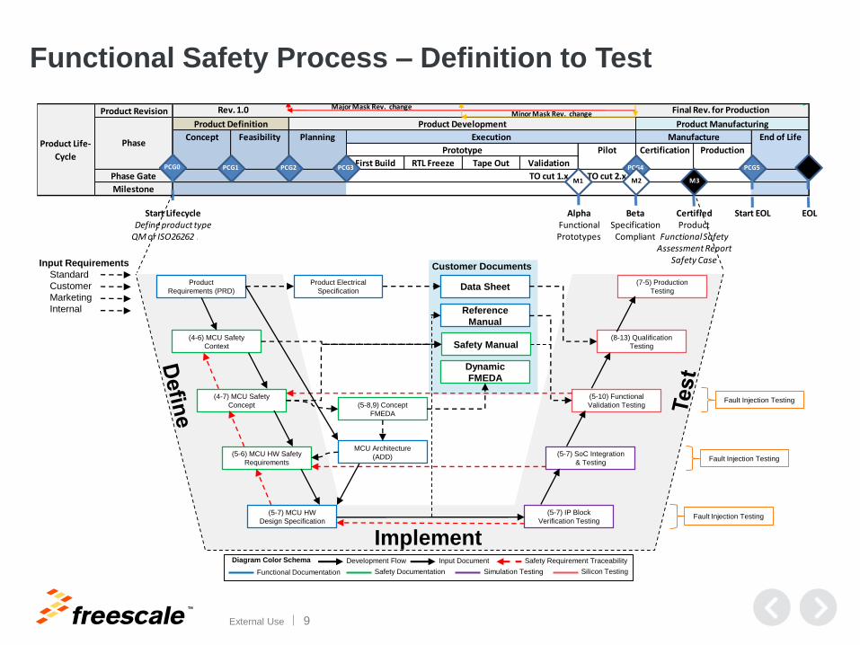
Product Revision
First Build RTL Freeze Tape Out Validation
Phase Gate TO cut 1.x TO cut 2.x
Milestone
Product Life-
Cycle
Phase
Product Definition Product Development Product Manufacturing
Concept Feasibility Planning Execution Manufacture End of Life
Prototype Pilot Certification Production
PCG0 PCG1 PCG2 PCG3 PCG4 PCG5
M1 M2 M3
Start LifecycleDefine product type
QM or ISO26262 ASIL
Rev. 1.0 Final Rev. for ProductionMajor Mask Rev. changeMinor Mask Rev. change
Certified Product
Functional SafetyAssessment Report
Safety Case
BetaSpecification
Compliant
AlphaFunctionalPrototypes
Start EOL EOL
Functional Safety Process – Definition to Test
(4-6) MCU Safety
Context
(4-7) MCU Safety
Concept
(5-6) MCU HW Safety
Requirements
(5-7) MCU HW
Design Specification
(5-8,9) Concept
FMEDA
(5-10) Functional
Validation Testing
(5-7) IP Block
Verification Testing
(8-13) Qualification
Testing
(5-7) SoC Integration
& Testing
Implement
Safety Documentation Silicon TestingSimulation TestingFunctional Documentation
Diagram Color Schema Development Flow Safety Requirement Traceability
Fault Injection Testing
Fault Injection Testing
Fault Injection Testing
Input Requirements
Standard
Customer
Marketing
Internal
Product
Requirements (PRD)
MCU Architecture
(ADD)
Data SheetProduct Electrical
Specification
Reference
Manual
Safety Manual
Dynamic
FMEDA
(7-5) Production
Testing
Customer Documents
Input Document
TM
External Use 10
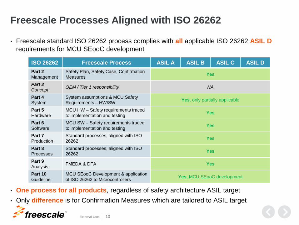
Freescale Processes Aligned with ISO 26262
• Freescale standard ISO 26262 process complies with all applicable ISO 26262 ASIL D
requirements for MCU SEooC development
• One process for all products, regardless of safety architecture ASIL target
• Only difference is for Confirmation Measures which are tailored to ASIL target
ISO 26262 Freescale Process ASIL A ASIL B ASIL C ASIL D
Part 2
Management
Safety Plan, Safety Case, Confirmation
MeasuresYes
Part 3
ConceptOEM / Tier 1 responsibility NA
Part 4
System
System assumptions & MCU Safety
Requirements – HW/SWYes, only partially applicable
Part 5
Hardware
MCU HW – Safety requirements traced
to implementation and testingYes
Part 6
Software
MCU SW – Safety requirements traced
to implementation and testingYes
Part 7
Production
Standard processes, aligned with ISO
26262Yes
Part 8
Processes
Standard processes, aligned with ISO
26262Yes
Part 9
AnalysisFMEDA & DFA Yes
Part 10
Guideline
MCU SEooC Development & application
of ISO 26262 to MicrocontrollersYes, MCU SEooC development
TM
External Use 11
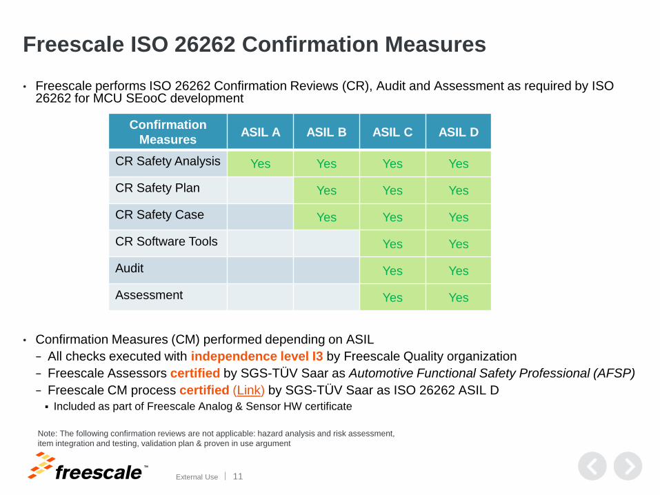
Freescale ISO 26262 Confirmation Measures
• Freescale performs ISO 26262 Confirmation Reviews (CR), Audit and Assessment as required by ISO 26262 for MCU SEooC development
• Confirmation Measures (CM) performed depending on ASIL
− All checks executed with independence level I3 by Freescale Quality organization
− Freescale Assessors certified by SGS-TÜV Saar as Automotive Functional Safety Professional (AFSP)
− Freescale CM process certified (Link) by SGS-TÜV Saar as ISO 26262 ASIL D
Included as part of Freescale Analog & Sensor HW certificate
Confirmation
MeasuresASIL A ASIL B ASIL C ASIL D
CR Safety Analysis Yes Yes Yes Yes
CR Safety Plan Yes Yes Yes
CR Safety Case Yes Yes Yes
CR Software Tools Yes Yes
Audit Yes Yes
Assessment Yes Yes
Note: The following confirmation reviews are not applicable: hazard analysis and risk assessment,
item integration and testing, validation plan & proven in use argument
TM
External Use 12
MCU Safety Context and Safety
Concepts
TM
External Use 13
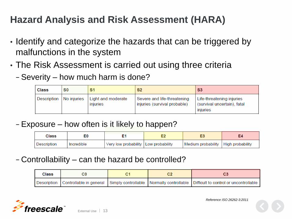
Hazard Analysis and Risk Assessment (HARA)
• Identify and categorize the hazards that can be triggered by
malfunctions in the system
• The Risk Assessment is carried out using three criteria
− Severity – how much harm is done?
− Exposure – how often is it likely to happen?
− Controllability – can the hazard be controlled?
Reference ISO 26262-3:2011
TM
External Use 14
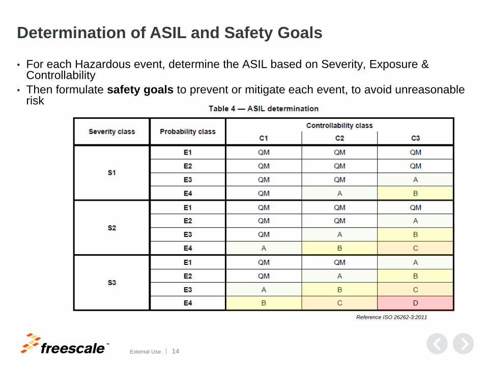
Determination of ASIL and Safety Goals
• For each Hazardous event, determine the ASIL based on Severity, Exposure & Controllability
• Then formulate safety goals to prevent or mitigate each event, to avoid unreasonable risk
Reference ISO 26262-3:2011
TM
External Use 15
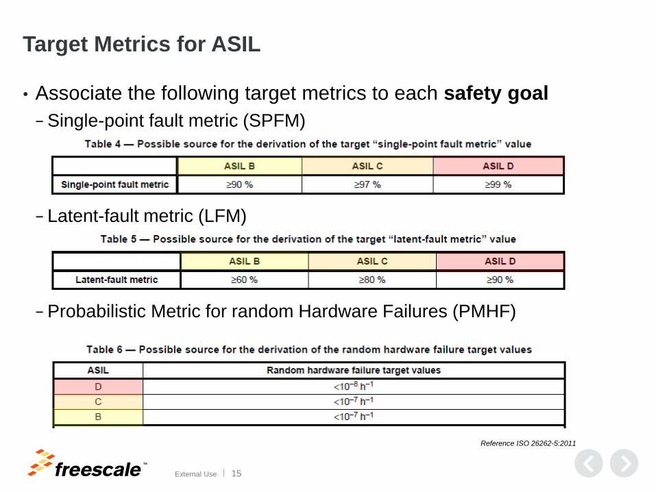
Target Metrics for ASIL
• Associate the following target metrics to each safety goal
− Single-point fault metric (SPFM)
− Latent-fault metric (LFM)
− Probabilistic Metric for random Hardware Failures (PMHF)
Reference ISO 26262-5:2011
TM
External Use 16
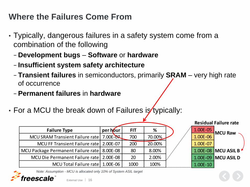
Where the Failures Come From
• Typically, dangerous failures in a safety system come from a
combination of the following
− Development bugs – Software or hardware
− Insufficient system safety architecture
− Transient failures in semiconductors, primarily SRAM – very high rate
of occurrence
− Permanent failures in hardware
• For a MCU the break down of Failures is typically:
Failure Type per hour FIT %
MCU SRAM Transient Failure rate 7.00E-07 700 70.00%
MCU FF Transient Failure rate 2.00E-07 200 20.00%
MCU Package Permanent Failure rate 8.00E-08 80 8.00%
MCU Die Permanent Failure rate 2.00E-08 20 2.00%
MCU Total Failure rate 1.00E-06 1000 100%
1.00E-05
1.00E-06
1.00E-07
1.00E-08 MCU ASIL B
1.00E-09 MCU ASIL D
1.00E-10
MCU Raw
Residual Failure rate
Note: Assumption - MCU is allocated only 10% of System ASIL target
TM
External Use 17
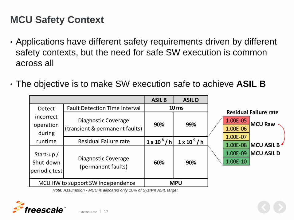
MCU Safety Context
• Applications have different safety requirements driven by different
safety contexts, but the need for safe SW execution is common
across all
• The objective is to make SW execution safe to achieve ASIL B
1.00E-05
1.00E-06
1.00E-07
1.00E-08 MCU ASIL B
1.00E-09 MCU ASIL D
1.00E-10
MCU Raw
Residual Failure rate
ASIL B ASIL D
Fault Detection Time Interval
Diagnostic Coverage
(transient & permanent faults)90% 99%
Residual Failure rate 1 x 10⁻⁸ / h 1 x 10⁻⁹ / h
Start-up /
Shut-down
periodic test
Diagnostic Coverage
(permanent faults)60% 90%
10 msDetect
incorrect
operation
during
runtime
MCU HW to support SW Independence MPUNote: Assumption - MCU is allocated only 10% of System ASIL target
TM
External Use 18
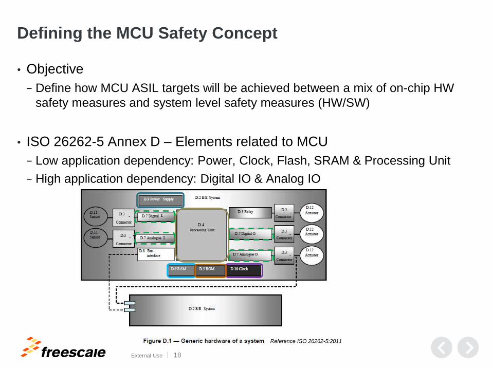
Defining the MCU Safety Concept
• Objective
− Define how MCU ASIL targets will be achieved between a mix of on-chip HW
safety measures and system level safety measures (HW/SW)
• ISO 26262-5 Annex D – Elements related to MCU
− Low application dependency: Power, Clock, Flash, SRAM & Processing Unit
− High application dependency: Digital IO & Analog IO
Reference ISO 26262-5:2011
TM
External Use 19
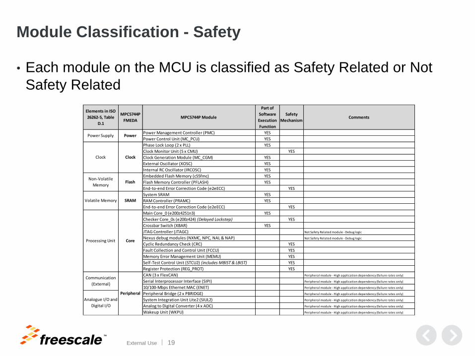
Module Classification - Safety
• Each module on the MCU is classified as Safety Related or Not
Safety Related
Elements in ISO
26262-5, Table
D.1
MPC5744P
FMEDAMPC5744P Module
Part of
Software
Execution
Function
Safety
MechanismComments
Power Management Controller (PMC) YES
Power Control Unit (MC_PCU) YES
Phase Lock Loop (2 x PLL) YES
Clock Monitor Unit (5 x CMU) YES
Clock Generation Module (MC_CGM) YES
External Oscillator (XOSC) YES
Internal RC Oscillator (IRCOSC) YES
Embedded Flash Memory (c55fmc) YES
Flash Memory Controller (PFLASH) YES
End-to-end Error Correction Code (e2eECC) YES
System SRAM YES
RAM Controller (PRAMC) YES
End-to-end Error Correction Code (e2eECC) YES
Main Core_0 (e200z4251n3) YES
Checker Core_0s (e200z424) (Delayed Lockstep) YES
Crossbar Switch (XBAR) YES
JTAG Controller (JTAGC) Not Safety Related module - Debug logic
Nexus debug modules (NXMC, NPC, NAL & NAP) Not Safety Related module - Debug logic
Cyclic Redundancy Check (CRC) YES
Fault Collection and Control Unit (FCCU) YES
Memory Error Management Unit (MEMU) YES
Self-Test Control Unit (STCU2) (includes MBIST & LBIST) YES
Register Protection (REG_PROT) YES
CAN (3 x FlexCAN) Peripheral module - High application dependency (failure rates only)
Serial Interprocessor Interface (SIPI) Peripheral module - High application dependency (failure rates only)
10/100-Mbps Ethernet MAC (ENET) Peripheral module - High application dependency (failure rates only)
Peripheral Bridge (2 x PBRIDGE) Peripheral module - High application dependency (failure rates only)
System Integration Unit Lite2 (SIUL2) Peripheral module - High application dependency (failure rates only)
Analog to Digital Converter (4 x ADC) Peripheral module - High application dependency (failure rates only)
Wakeup Unit (WKPU) Peripheral module - High application dependency (failure rates only)
FlashNon-Volatile
Memory
Volatile Memory SRAM
Peripheral
Analogue I/O and
Digital I/O
Power
Clock
Power Supply
Clock
Communication
(External)
CoreProcessing Unit
TM
External Use 20
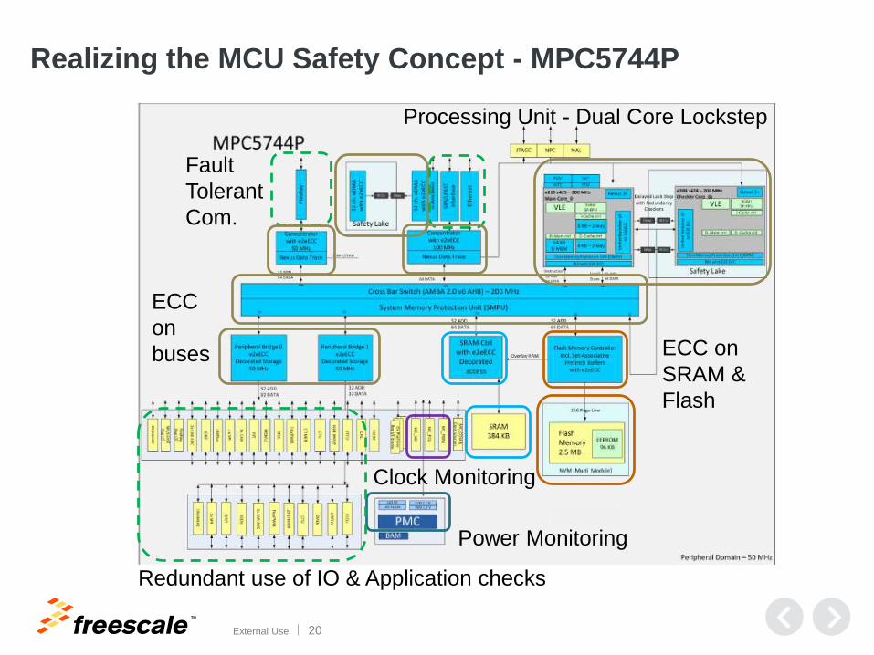
Realizing the MCU Safety Concept - MPC5744P
Power Monitoring
Clock Monitoring
ECC on
SRAM &
Flash
Processing Unit - Dual Core Lockstep
ECC
on
buses
Redundant use of IO & Application checks
Fault
Tolerant
Com.
TM
External Use 21
Standard Deliverables to Enable
the Customer
TM
External Use 22
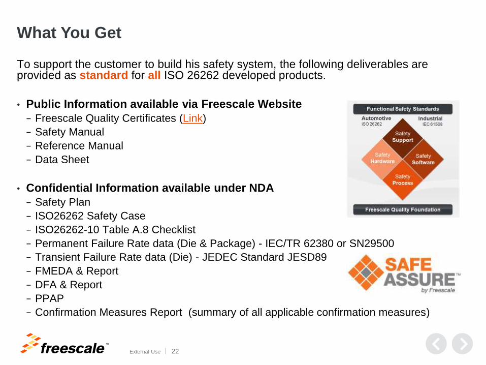
What You Get
To support the customer to build his safety system, the following deliverables are provided as standard for all ISO 26262 developed products.
• Public Information available via Freescale Website
− Freescale Quality Certificates (Link)
− Safety Manual
− Reference Manual
− Data Sheet
• Confidential Information available under NDA
− Safety Plan
− ISO26262 Safety Case
− ISO26262-10 Table A.8 Checklist
− Permanent Failure Rate data (Die & Package) - IEC/TR 62380 or SN29500
− Transient Failure Rate data (Die) - JEDEC Standard JESD89
− FMEDA & Report
− DFA & Report
− PPAP
− Confirmation Measures Report (summary of all applicable confirmation measures)
TM
External Use 23
Safety Manual
TM
External Use 24
Safety Manual
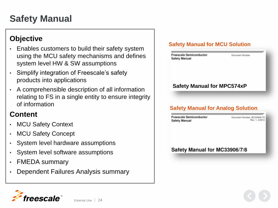
Objective
• Enables customers to build their safety system
using the MCU safety mechanisms and defines
system level HW & SW assumptions
• Simplify integration of Freescale’s safety
products into applications
• A comprehensible description of all information
relating to FS in a single entity to ensure integrity
of information
Content
• MCU Safety Context
• MCU Safety Concept
• System level hardware assumptions
• System level software assumptions
• FMEDA summary
• Dependent Failures Analysis summary
Safety Manual for Analog Solution
Safety Manual for MCU Solution
Safety Manual for MPC574xP
TM
External Use 25
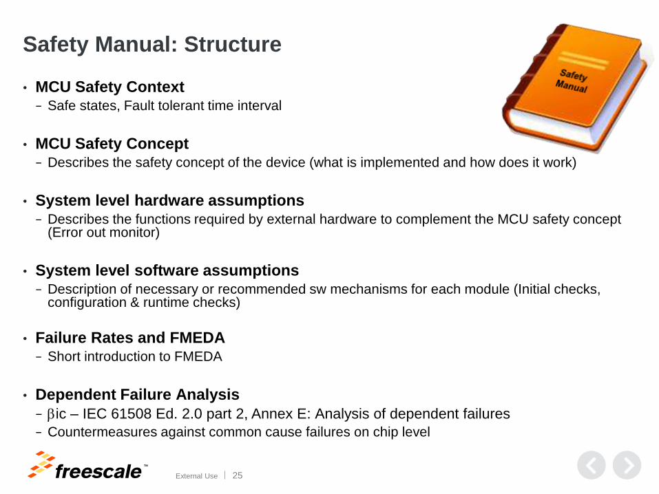
Safety Manual: Structure
• MCU Safety Context− Safe states, Fault tolerant time interval
• MCU Safety Concept − Describes the safety concept of the device (what is implemented and how does it work)
• System level hardware assumptions− Describes the functions required by external hardware to complement the MCU safety concept
(Error out monitor)
• System level software assumptions− Description of necessary or recommended sw mechanisms for each module (Initial checks,
configuration & runtime checks)
• Failure Rates and FMEDA− Short introduction to FMEDA
• Dependent Failure Analysis
− bic – IEC 61508 Ed. 2.0 part 2, Annex E: Analysis of dependent failures
− Countermeasures against common cause failures on chip level
TM
External Use 26
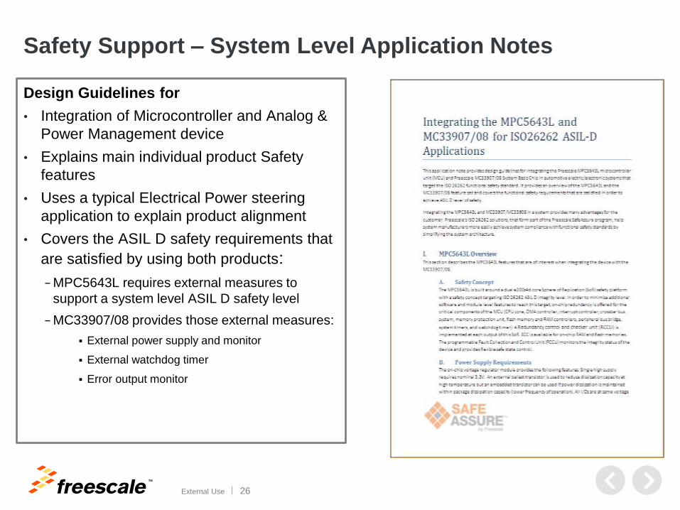
Safety Support – System Level Application Notes
Design Guidelines for
• Integration of Microcontroller and Analog &
Power Management device
• Explains main individual product Safety
features
• Uses a typical Electrical Power steering
application to explain product alignment
• Covers the ASIL D safety requirements that
are satisfied by using both products:
− MPC5643L requires external measures to
support a system level ASIL D safety level
− MC33907/08 provides those external measures:
External power supply and monitor
External watchdog timer
Error output monitor
TM
External Use 27
Dynamic FMEDA
TM
External Use 28
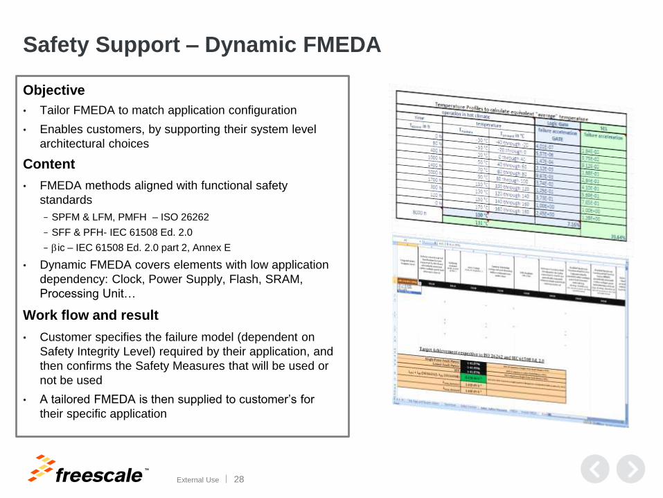
Safety Support – Dynamic FMEDA
Objective
• Tailor FMEDA to match application configuration
• Enables customers, by supporting their system level
architectural choices
Content
• FMEDA methods aligned with functional safety
standards
− SPFM & LFM, PMFH – ISO 26262
− SFF & PFH- IEC 61508 Ed. 2.0
− bic – IEC 61508 Ed. 2.0 part 2, Annex E
• Dynamic FMEDA covers elements with low application
dependency: Clock, Power Supply, Flash, SRAM,
Processing Unit…
Work flow and result
• Customer specifies the failure model (dependent on
Safety Integrity Level) required by their application, and
then confirms the Safety Measures that will be used or
not be used
• A tailored FMEDA is then supplied to customer’s for
their specific application
TM
External Use 29
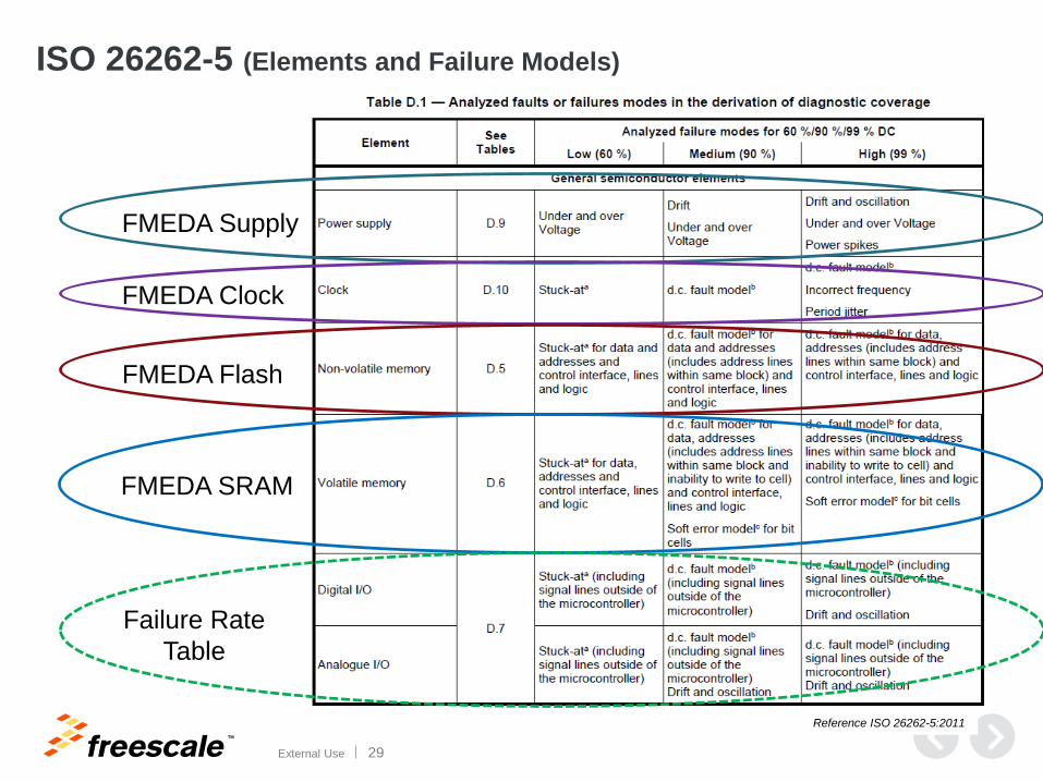
ISO 26262-5 (Elements and Failure Models)
FMEDA Supply
FMEDA Clock
FMEDA Flash
FMEDA SRAM
Failure Rate
Table
Reference ISO 26262-5:2011
TM
External Use 30
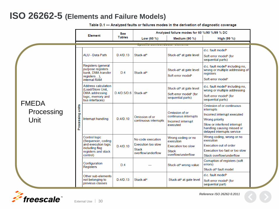
ISO 26262-5 (Elements and Failure Models)
FMEDA
Processing
Unit
Reference ISO 26262-5:2011
TM
External Use 31
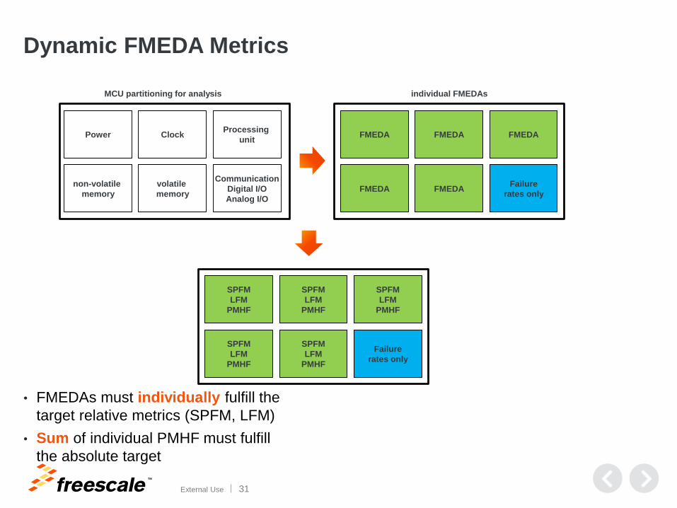
Dynamic FMEDA Metrics
• FMEDAs must individually fulfill the
target relative metrics (SPFM, LFM)
• Sum of individual PMHF must fulfill
the absolute target
Power Clock
non-volatile
memory
volatile
memory
Processing
unit
Communication
Digital I/O
Analog I/O
FMEDA FMEDA
FMEDA FMEDA
FMEDA
Failure
rates only
MCU partitioning for analysis individual FMEDAs
SPFM
LFM
PMHF
SPFM
LFM
PMHF
SPFM
LFM
PMHF
SPFM
LFM
PMHF
SPFM
LFM
PMHF
Failure
rates only
TM
External Use 32
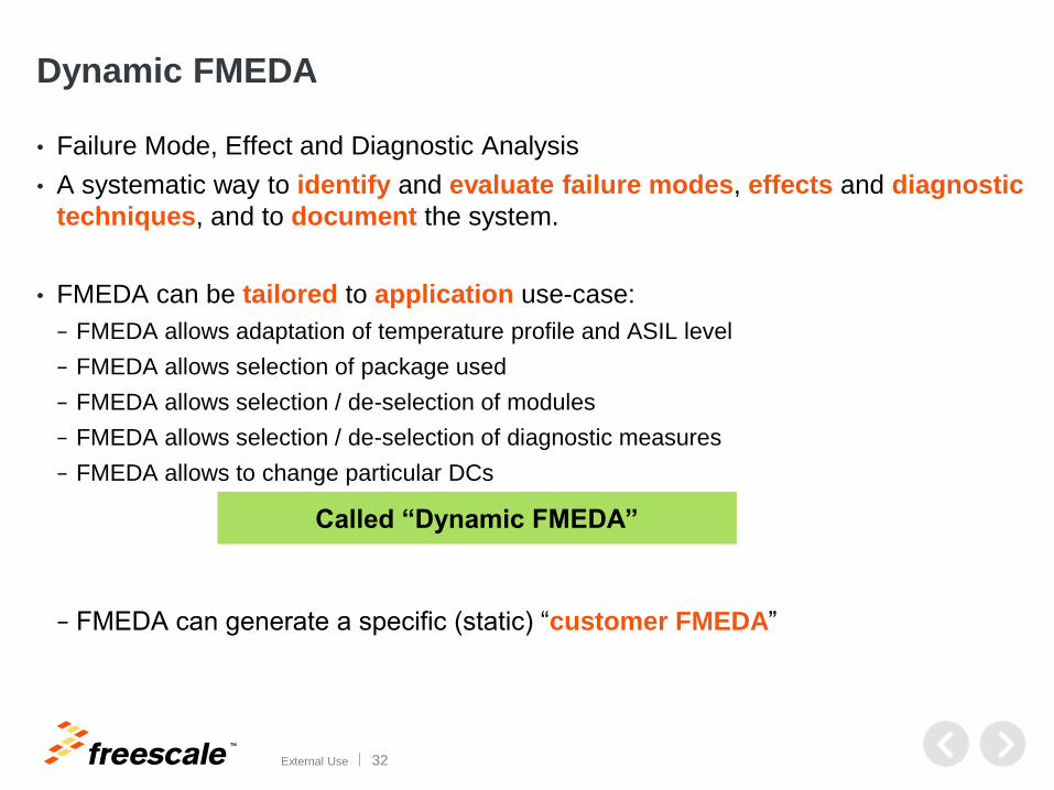
Dynamic FMEDA
• Failure Mode, Effect and Diagnostic Analysis
• A systematic way to identify and evaluate failure modes, effects and diagnostic
techniques, and to document the system.
• FMEDA can be tailored to application use-case:
− FMEDA allows adaptation of temperature profile and ASIL level
− FMEDA allows selection of package used
− FMEDA allows selection / de-selection of modules
− FMEDA allows selection / de-selection of diagnostic measures
− FMEDA allows to change particular DCs
− FMEDA can generate a specific (static) “customer FMEDA”
Called “Dynamic FMEDA”
TM
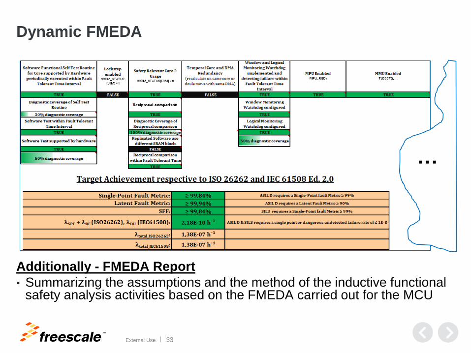
External Use 33
…
Dynamic FMEDA
Additionally - FMEDA Report
• Summarizing the assumptions and the method of the inductive functional safety analysis activities based on the FMEDA carried out for the MCU
TM
External Use 34
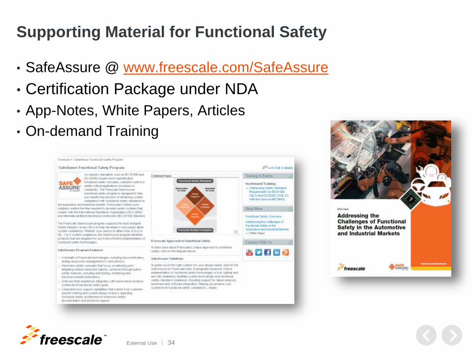
Supporting Material for Functional Safety
• SafeAssure @ www.freescale.com/SafeAssure
• Certification Package under NDA
• App-Notes, White Papers, Articles
• On-demand Training
TM
© 2015 Freescale Semiconductor, Inc. | External Use
www.Freescale.com