Embed Size (px)
Citation preview

A
www.rinnai.us
Model V2532W
•
How to use your NewContinuous Flow
Water Heater
WARNING: If the information in these instructions is not followed
exactly, a fire or explosion may result causing property damage,
personal injury or death.
– Do not store or use gasoline or other flammable vapors and
liquids in the vicinity of this or any other appliance.
– WHAT TO DO IF YOU SMELL GAS
• Do not try to light any appliance.
• Do not touch any electrical switch; do not use any phone in
your building.
• Immediately call your gas supplier from a neighbor's phone.
Follow the gas supplier's instructions.
• If you cannot reach your gas supplier, call the fire department.
– Installation and service must be performed by a qualified
installer, service agency or the gas supplier.
(Residential outdoor unit)
ANS Z21.10.3 CSA 4.3

A
www.rinnai.us Model V2532W2
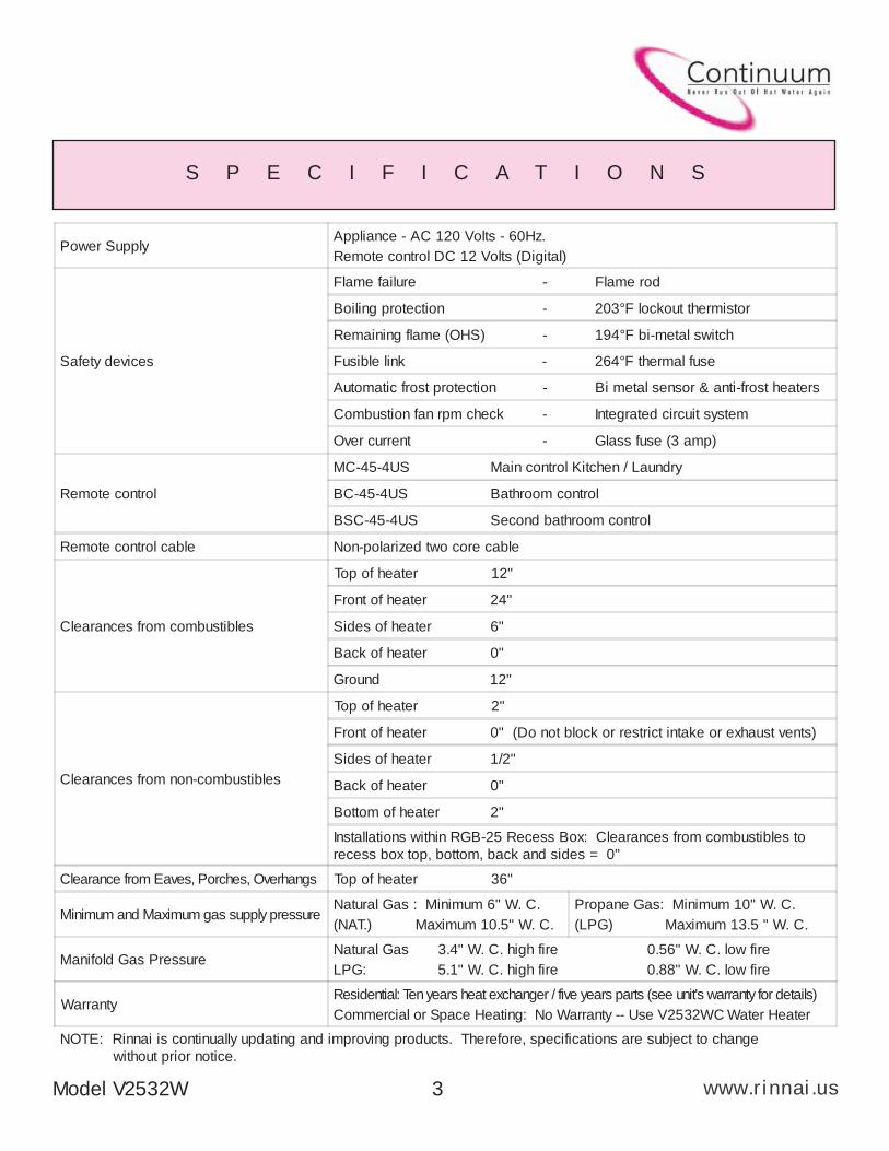
S P E C I F I C A T I O N S
Type of appliance Temperature controlled continuous flow gas hot water system
Operation With / without remote controls, mounted in kitchen, bathroom, etc.
Exhaust system Direct Vent - Forced combustion
Rinnai model number REU-V2532W-US
Maximum/Minimum gas rate (Input BTU's)199,000 BTU's - 15,000 BTU's Natural Gas
199,000 BTU's - 15,000 BTU's Propane Gas
Thermal Efficiency Natural Gas: 84% Propane: 85%
Energy Factor (EF) Natural Gas: 0.82 Propane: 0.84
Capacity (Gallons 1st Hour @ 90°F rise) Natural Gas: 218 Propane: 227
NOx Emissions (at 3% O
2) less than 40 ppm
Hot water capacity, (50°F rise) 0.5 to 6.5 GPM
Maximum hot water capacity, (35°F rise) 8.5 GPM
Setpoint Temperature (without remote) Factory setting - 120°F
Temperature range with optional remote
Keypads connected
MC controller : 96 - 140°F
BC and BSC controller : 96 - 120°F
Approved gas type Natural or Propane - Ensure unit matches gas type it's being installed on.
Installation Outdoor Installation Only
Dimensions
Height 23 5/8"
Width 13 3/4"
Depth 8 7/8"
Weight 46 Lbs.
Connections
Gas supply 3/4" MNPT
Cold water inlet 3/4" MNPT
Hot water outlet 3/4" MNPT
Ignition system Direct electronic ignition
Electrical consumption
Normal 63 watts
Standby 5.5 watts
Anti-frost protection 84 watts
Water temperature control Simulation feedforward and feedback.
Water flow controlWater flow sensor, electronic water control device, and electronic by-pass
control device
Recommended Minimum water
supply pressure20 PSI (Rinnai recommends 50-80 PSI for maximum performance)
Maximum water supply pressure 150 PSI
A
www.rinnai.usModel V2532W 3
S P E C I F I C A T I O N S
Power SupplyAppliance - AC 120 Volts - 60Hz.
Remote control DC 12 Volts (Digital)
Safety devices
Flame failure - Flame rod
Boiling protection - 203°F lockout thermistor
Remaining flame (OHS) - 194°F bi-metal switch
Fusible link - 264°F thermal fuse
Automatic frost protection - Bi metal sensor & anti-frost heaters
Combustion fan rpm check - Integrated circuit system
Over current - Glass fuse (3 amp)
Remote control
MC-45-4US Main control Kitchen / Laundry
BC-45-4US Bathroom control
BSC-45-4US Second bathroom control
Remote control cable Non-polarized two core cable
Clearances from combustibles
Top of heater 12"
Front of heater 24"
Sides of heater 6"
Back of heater 0"
Ground 12"
Clearances from non-combustibles
Top of heater 2"
Front of heater 0" (Do not block or restrict intake or exhaust vents)
Sides of heater 1/2"
Back of heater 0"
Bottom of heater 2"
Installations within RGB-25 Recess Box: Clearances from combustibles to
recess box top, bottom, back and sides = 0"
Clearance from Eaves, Porches, Overhangs Top of heater 36"
Minimum and Maximum gas supply pressureNatural Gas : Minimum 6" W. C.
(NAT.) Maximum 10.5" W. C.
Propane Gas: Minimum 10" W. C.
(LPG) Maximum 13.5 " W. C.
Manifold Gas PressureNatural Gas 3.4" W. C. high fire 0.56" W. C. low fire
LPG: 5.1" W. C. high fire 0.88" W. C. low fire
WarrantyResidential: Ten years heat exchanger / five years parts (see unit's warranty for details)
Commercial or Space Heating: No Warranty -- Use V2532WC Water Heater
NOTE: Rinnai is continually updating and improving products. Therefore, specifications are subject to change
without prior notice.
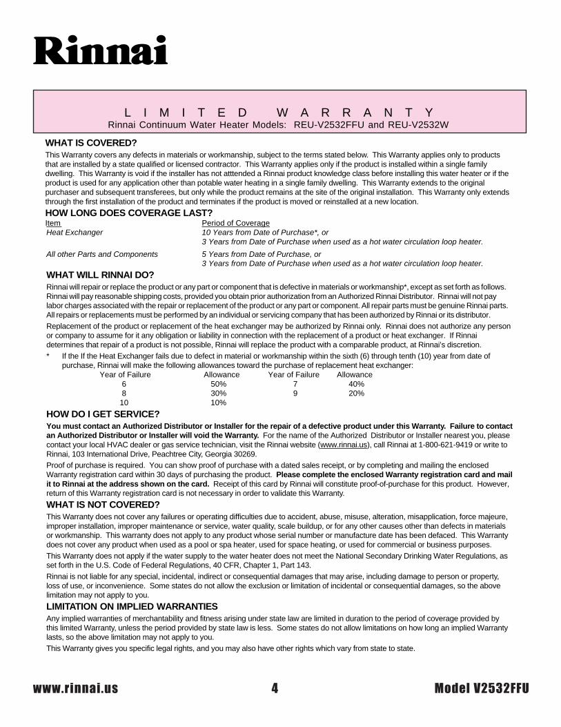
L I M I T E D W A R R A N T YRinnai Continuum Water Heater Models: REU-V2532FFU and REU-V2532W
WHAT IS COVERED?This Warranty covers any defects in materials or workmanship, subject to the terms stated below. This Warranty applies only to productsthat are installed by a state qualified or licensed contractor. This Warranty applies only if the product is installed within a single familydwelling. This Warranty is void if the installer has not atttended a Rinnai product knowledge class before installing this water heater or if theproduct is used for any application other than potable water heating in a single family dwelling. This Warranty extends to the originalpurchaser and subsequent transferees, but only while the product remains at the site of the original installation. This Warranty only extendsthrough the first installation of the product and terminates if the product is moved or reinstalled at a new location.
HOW LONG DOES COVERAGE LAST?Item Period of CoverageHeat Exchanger 10 Years from Date of Purchase*, or
3 Years from Date of Purchase when used as a hot water circulation loop heater.
All other Parts and Components 5 Years from Date of Purchase, or3 Years from Date of Purchase when used as a hot water circulation loop heater.
WHAT WILL RINNAI DO?Rinnai will repair or replace the product or any part or component that is defective in materials or workmanship*, except as set forth as follows.Rinnai will pay reasonable shipping costs, provided you obtain prior authorization from an Authorized Rinnai Distributor. Rinnai will not paylabor charges associated with the repair or replacement of the product or any part or component. All repair parts must be genuine Rinnai parts.All repairs or replacements must be performed by an individual or servicing company that has been authorized by Rinnai or its distributor.Replacement of the product or replacement of the heat exchanger may be authorized by Rinnai only. Rinnai does not authorize any personor company to assume for it any obligation or liability in connection with the replacement of a product or heat exchanger. If Rinnaidetermines that repair of a product is not possible, Rinnai will replace the product with a comparable product, at Rinnai’s discretion.* If the If the Heat Exchanger fails due to defect in material or workmanship within the sixth (6) through tenth (10) year from date of
purchase, Rinnai will make the following allowances toward the purchase of replacement heat exchanger: Year of Failure Allowance Year of Failure Allowance 6 50% 7 40% 8 30% 9 20% 10 10%
HOW DO I GET SERVICE?You must contact an Authorized Distributor or Installer for the repair of a defective product under this Warranty. Failure to contactan Authorized Distributor or Installer will void the Warranty. For the name of the Authorized Distributor or Installer nearest you, pleasecontact your local HVAC dealer or gas service technician, visit the Rinnai website (www.rinnai.us), call Rinnai at 1-800-621-9419 or write toRinnai, 103 International Drive, Peachtree City, Georgia 30269.Proof of purchase is required. You can show proof of purchase with a dated sales receipt, or by completing and mailing the enclosedWarranty registration card within 30 days of purchasing the product. Please complete the enclosed Warranty registration card and mailit to Rinnai at the address shown on the card. Receipt of this card by Rinnai will constitute proof-of-purchase for this product. However,return of this Warranty registration card is not necessary in order to validate this Warranty.
WHAT IS NOT COVERED?This Warranty does not cover any failures or operating difficulties due to accident, abuse, misuse, alteration, misapplication, force majeure,improper installation, improper maintenance or service, water quality, scale buildup, or for any other causes other than defects in materialsor workmanship. This warranty does not apply to any product whose serial number or manufacture date has been defaced. This Warrantydoes not cover any product when used as a pool or spa heater, used for space heating, or used for commercial or business purposes.This Warranty does not apply if the water supply to the water heater does not meet the National Secondary Drinking Water Regulations, asset forth in the U.S. Code of Federal Regulations, 40 CFR, Chapter 1, Part 143.Rinnai is not liable for any special, incidental, indirect or consequential damages that may arise, including damage to person or property,loss of use, or inconvenience. Some states do not allow the exclusion or limitation of incidental or consequential damages, so the abovelimitation may not apply to you.
LIMITATION ON IMPLIED WARRANTIESAny implied warranties of merchantability and fitness arising under state law are limited in duration to the period of coverage provided bythis limited Warranty, unless the period provided by state law is less. Some states do not allow limitations on how long an implied Warrantylasts, so the above limitation may not apply to you.This Warranty gives you specific legal rights, and you may also have other rights which vary from state to state.
A
www.rinnai.usModel V2532W 5
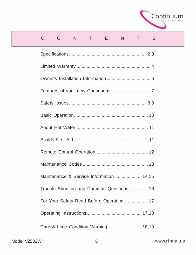
C O N T E N T S
Specifications.............................................................. 2,3
Limited Warranty ........................................................... 4
Owner's Installation Information ................................... 6
Features of your new Continuum ................................ 7
Safety Issues .............................................................. 8,9
Basic Operation........................................................... 10
About Hot Water ......................................................... 11
Scalds-First Aid ........................................................... 11
Remote Control Operation ......................................... 12
Maintenance Codes .................................................... 13
Maintenance & Service Information...................... 14,15
Trouble Shooting and Common Questions ............... 16
For Your Safety Read Before Operating ................... 17
Operating Instructions............................................ 17,18
Care & Lime Condition Warning ........................... 18,19
A
www.rinnai.us
O W N E R ’ S I N S T A L L A T I O N I N F O R M A T I O N
IMPORTANT!
All Rinnai water heaters MUST be installed by a state qualified orlicensed contractor. Failure to comply with your local and state codespertaining to water heater installations will void the warranty on saidwater heater(s). It is the responsibility of the person having the unitinstalled to ensure the contractor has the proper licences and permitsfor his state. In addition to the above, Rinnai requires all contractorsattend a product knowledge class before installing our water heaters.This requirement MUST be met in order for your product’s warranty tobe valid. Failure to comply with your local and state codes will resultin non-compliance and void the warranty of the product beinginstalled.
This appliance must be installed in accordance with local codes, or in theabsence of local codes, the National Fuel Gas Code, ANSI Z223.1 and/or theCAN/CGA-B149, Installation Codes.
Install this product outdoors ONLY, DO NOT install indoors.
Do Not use this appliance if any part has been underwater.Immediately call a qualified service technician to inspect the applianceand to replace any part of the control system and any gas controlwhich has been underwater.
Detailed instructions on the proper installation practices to follow forthe installation of your new continuous hot water heater are includedat the back of this manual.
Model V2532W6
A
Model V2532W 7 www.rinnai.us
F E A T U R E S O F Y O U R N E W C O N T I N U U M
F
The Continuum V2532W is one of the most advanced water heaters available. It produceshot water continuously at the temperature preset in the unit or at the temperature set on theremote temperature controller. Installation of the remote temperature controller isrecommended for optimum performance.
F The Continuum V2532W never runs out of hot water. While electricity, water and gassupplies are connected, the Continuum V2532W will produce hot water whenever thewater flow rate through the unit exceeds 0.6 gpm and the temperature rise through theunit exceeds 45°F.
F
The gas burner lights automatically when the hot water tap is opened, and goes out whenthe tap is closed. Ignition is electronic, there is no pilot light. When the hot water tap is off,no gas is used. You save energy and money with the Continuum V2532W.
F The temperature of the outgoing hot water is constantly monitored by a built in sensor. If thetemperature of the outgoing water rises to more than 6 degrees above the selectedtemperature (shown on the optional digital remote control) the gas burner will automaticallygo out. The gas burner will re-ignite once the outgoing hot water temperature falls below theselected temperature.
F With the remote control installed the water temperature is adjustable from 96 to 140°F withthe main controller and from 96 to 120°F with the bath controller. The water temperaturecannot be set to a temperature other than 120°F without the use of an optional remotecontrol unit.
F Error messages are displayed on the remote control units, simplifying service calls.
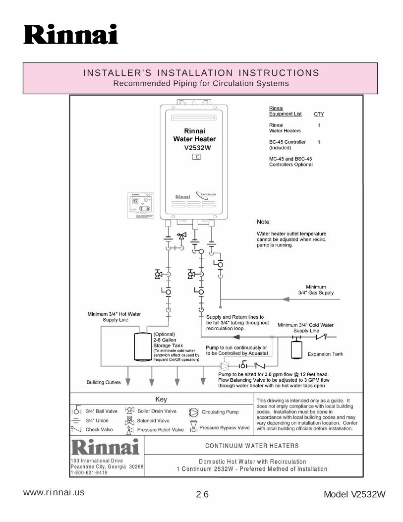
F The Continuum V2532W incorporates a device to limit the temperature fluctuations (coldwater sandwich effect) when the water is rapidly turned off, then on again. To eliminate thecold water sandwich effect completely, the Continuum V2532W can be installed with acirculation loop, with a small storage tank, as shown on page 26.
F The sound (noise) level from the Continuum V2532W is very low.
F The Continuum V2532W is a very compact power vented device. It saves valuable floor andwall space.
A
www.rinnai.us
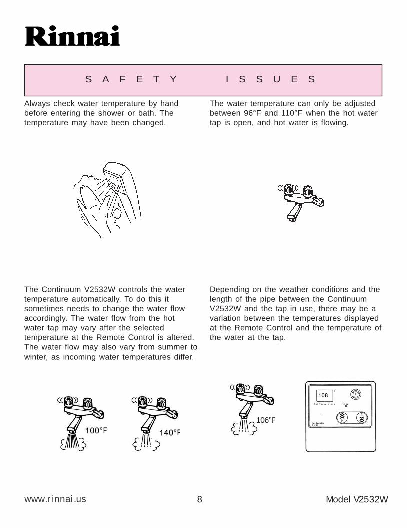
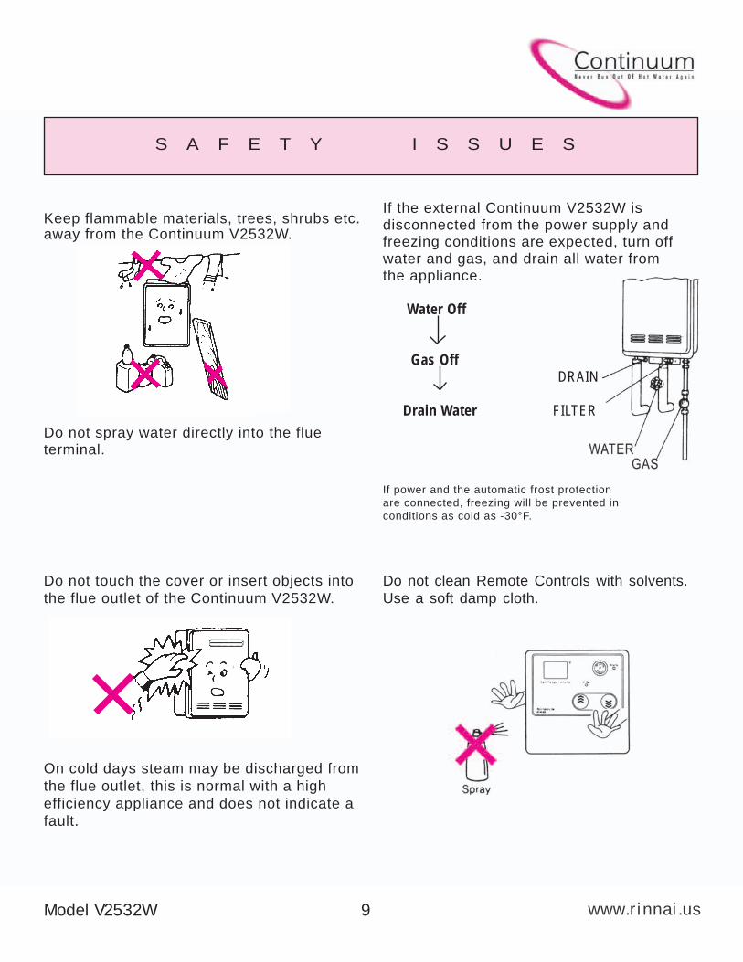
S A F E T Y I S S U E S
The water temperature can only be adjusted
between 96°F and 110°F when the hot water
tap is open, and hot water is flowing.
Always check water temperature by hand
before entering the shower or bath. The
temperature may have been changed.
Depending on the weather conditions and the
length of the pipe between the Continuum
V2532W and the tap in use, there may be a
variation between the temperatures displayed
at the Remote Control and the temperature of
the water at the tap.
The Continuum V2532W controls the water
temperature automatically. To do this it
sometimes needs to change the water flow
accordingly. The water flow from the hot
water tap may vary after the selected
temperature at the Remote Control is altered.
The water flow may also vary from summer to
winter, as incoming water temperatures differ.
106°F
Model V2532W8
A
www.rinnai.us
S A F E T Y I S S U E S
Do not touch the cover or insert objects into
the flue outlet of the Continuum V2532W.
On cold days steam may be discharged from
the flue outlet, this is normal with a high
efficiency appliance and does not indicate a
fault.
If the external Continuum V2532W isdisconnected from the power supply andfreezing conditions are expected, turn offwater and gas, and drain all water fromthe appliance.
Water Off
Gas Off
DRAIN
Drain Water FILTER
If power and the automatic frost protection
are connected, freezing will be prevented in
conditions as cold as -30°F.
Keep flammable materials, trees, shrubs etc.away from the Continuum V2532W.
Do not spray water directly into the flueterminal.
Do not clean Remote Controls with solvents.
Use a soft damp cloth.
Model V2532W 9
A
www.rinnai.us Model V2532W1 0
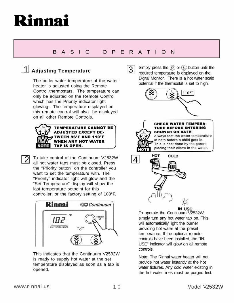
B A S I C O P E R A T I O N
To operate the Continuum V2532Wsimply turn any hot water tap on. Thiswill automatically light the burnerproviding hot water at the presettemperature. If the optional remotecontrols have been installed, the “INUSE” indicator will glow on all remotecontrols.
Note: The Rinnai water heater will notprovide hot water instantly at the hotwater fixtures. Any cold water existing inthe hot water lines must be purged first.
Adjusting Temperature 1
To take control of the Continuum V2532Wall hot water taps must be closed. Pressthe "Priority button" on the controller youwant to set the temperature with. The"Priority" indicator light will glow and the“Set Temperature” display will show thelast temperature setpoint for thiscontroller, or the factory setting of 108°F.
The outlet water temperature of the waterheater is adjusted using the RemoteControl thermostats. The temperature canonly be adjusted on the Remote Controlwhich has the Priority indicator lightglowing. The temperature displayed onthis remote control will also be displayedon all other Remote Controls.
3 Simply press the or button until therequired temperature is displayed on theDigital Monitor. There is a hot water scaldpotential if the thermostat is set to high.
42
This indicates that the Continuum V2532Wis ready to supply hot water at the settemperature displayed as soon as a tap isopened.
A
www.rinnai.us
BURN
Model V2532W 1 1
A B O U T H O T W A T E R
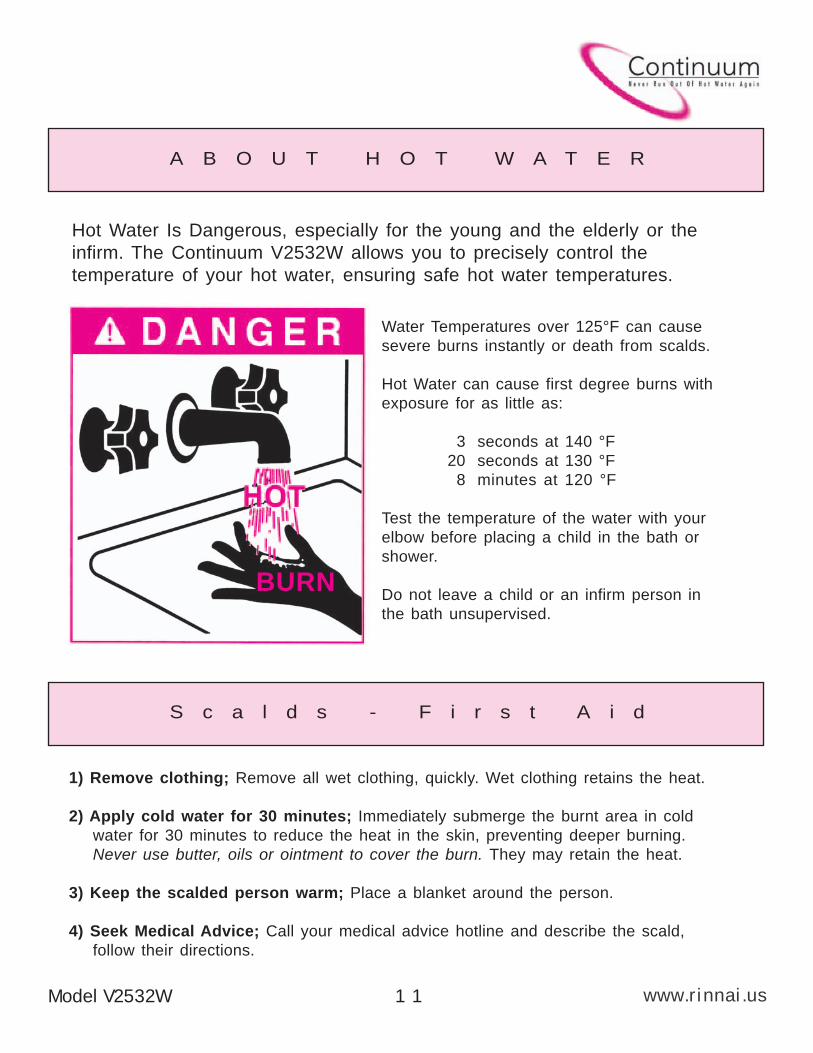
Hot Water Is Dangerous, especially for the young and the elderly or the
infirm. The Continuum V2532W allows you to precisely control the
temperature of your hot water, ensuring safe hot water temperatures.
Water Temperatures over 125°F can cause
severe burns instantly or death from scalds.
Hot Water can cause first degree burns with
exposure for as little as:
3 seconds at 140 °F
20 seconds at 130 °F
8 minutes at 120 °F
Test the temperature of the water with your
elbow before placing a child in the bath or
shower.
Do not leave a child or an infirm person in
the bath unsupervised.
S c a l d s - F i r s t A i d
1) Remove clothing; Remove all wet clothing, quickly. Wet clothing retains the heat.
2) Apply cold water for 30 minutes; Immediately submerge the burnt area in cold
water for 30 minutes to reduce the heat in the skin, preventing deeper burning.
Never use butter, oils or ointment to cover the burn. They may retain the heat.
3) Keep the scalded person warm; Place a blanket around the person.
4) Seek Medical Advice; Call your medical advice hotline and describe the scald,
follow their directions.
A
www.rinnai.us
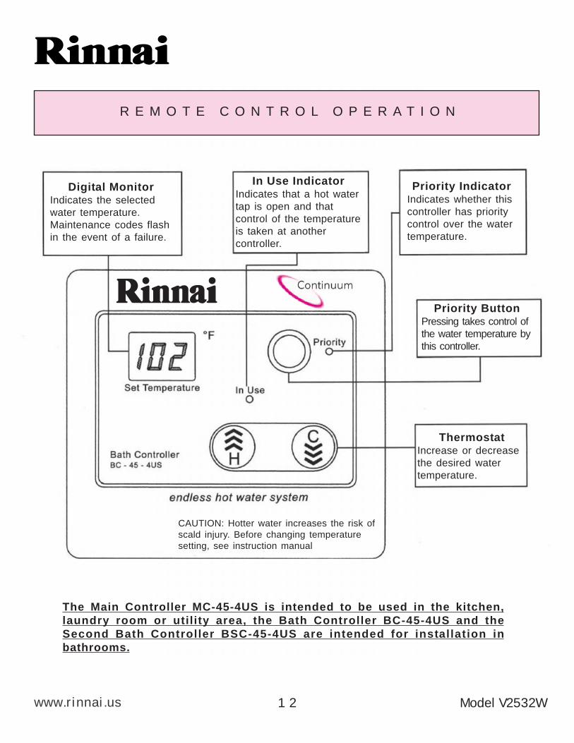
R E M O T E C O N T R O L O P E R A T I O N
CAUTION: Hotter water increases the risk of
scald injury. Before changing temperature
setting, see instruction manual
In Use IndicatorIndicates that a hot water
tap is open and that
control of the temperature
is taken at another
controller.
Digital MonitorIndicates the selected
water temperature.
Maintenance codes flash
in the event of a failure.
Priority IndicatorIndicates whether this
controller has priority
control over the water
temperature.
Priority ButtonPressing takes control of
the water temperature by
this controller.
ThermostatIncrease or decrease
the desired water
temperature.
The Main Controller MC-45-4US is intended to be used in the kitchen,
laundry room or utility area, the Bath Controller BC-45-4US and the
Second Bath Controller BSC-45-4US are intended for installation in
bathrooms.
Model V2532W1 2
A
www.rinnai.usModel V2532W 1 3
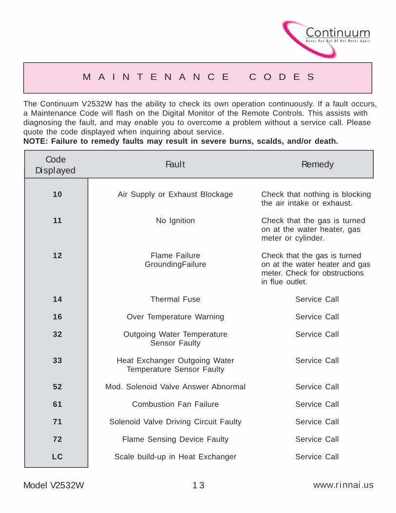
M A I N T E N A N C E C O D E S
The Continuum V2532W has the ability to check its own operation continuously. If a fault occurs,
a Maintenance Code will flash on the Digital Monitor of the Remote Controls. This assists with
diagnosing the fault, and may enable you to overcome a problem without a service call. Please
quote the code displayed when inquiring about service.
NOTE: Failure to remedy faults may result in severe burns, scalds, and/or death.
Code Displayed
Fault Remedy
Air Supply or Exhaust Blockage
No Ignition
Flame FailureGroundingFailure
Thermal Fuse
Over Temperature Warning
Outgoing Water TemperatureSensor Faulty
Heat Exchanger Outgoing WaterTemperature Sensor Faulty
Mod. Solenoid Valve Answer Abnormal
Combustion Fan Failure
Solenoid Valve Driving Circuit Faulty
Flame Sensing Device Faulty
Scale build-up in Heat Exchanger
Check that nothing is blockingthe air intake or exhaust.
Check that the gas is turnedon at the water heater, gasmeter or cylinder.
Check that the gas is turnedon at the water heater and gasmeter. Check for obstructionsin flue outlet.
Service Call
Service Call
Service Call
Service Call
Service Call
Service Call
Service Call
Service Call
Service Call
10
11
12
14
16
32
33
52
61
71
72
LC
A
www.rinnai.us Model V2532W1 4
Warning: Always turn off the electrical power supply, the manual gas
valve and the manual water control valve whenever servicing the unit.
The Continuum V2532W should be checked by a RinnaiCertified Technician once a year. A Rinnai CertifiedTechnician should perform any repairs that may benecessary.
The following items should be checked each inspection:
1) The area around the Continuum V2532W unit should be free from combustible
materials such as cloth, vegetation and building materials. (see page 9)
2) Check burners for presence of foreign debris.
3) Remove and clean the inlet water filter.
4) Keep the appliance area clear and free from combustible materials, gasoline,
and other flammable vapors and liquids.
5) Do not obstruct flow of combustion and ventilation air.
In the case of any fault or error message from the Continuum V2532W, first turn
all hot water taps off. Wait for 5 seconds. Turn the hot water tap back on. If the
error message still remains, call your Rinnai Authorized Service Representative
or Rinnai at 800-621-9419.
Should overheating occur or the gas supply fail to shutoff, turn off the manual
gas control valve to the appliance.
DO NOT ATTEMPT TO SERVICE YOUR Continuum V2532W YOURSELF.
Call a Rinnai Authorized Service Technician or call Rinnai at 800-621-9419.
M A I N T E N A N C E & S E R V I C E I N F O R M AT I O N
A
www.rinnai.usModel V2532W 1 5
MAINTENANCE SUGGESTIONS
This water heater has been designed and constructed
for a long performance life when installed and operated
properly under normal conditions. Regular inspections,
as outlined in this section, are strongly recommended
as a means of keeping your heater operating efficiently.
1. CleaningThe water heater must be cleaned annually.
Keep the water heater clear of dust and debris
especially in and around burner.
Cleaning procedures for the Continuum are as
follows:
1) Turn off and disconnect electrical power. Allow
to cool for one hour.
2) Remove the Front Panel by removing screws.
See parts breakdown on panels.
3) Use pressurized air to remove dust from around
main burner.
4) Use soft dry cloth to wipe cabinet.
DO NOT DAMAGE OR DISTORT ANY
PARTS OF HEATER.
DO NOT USE WET CLOTH OR
SPRAY CLEANERS ON BURNER.
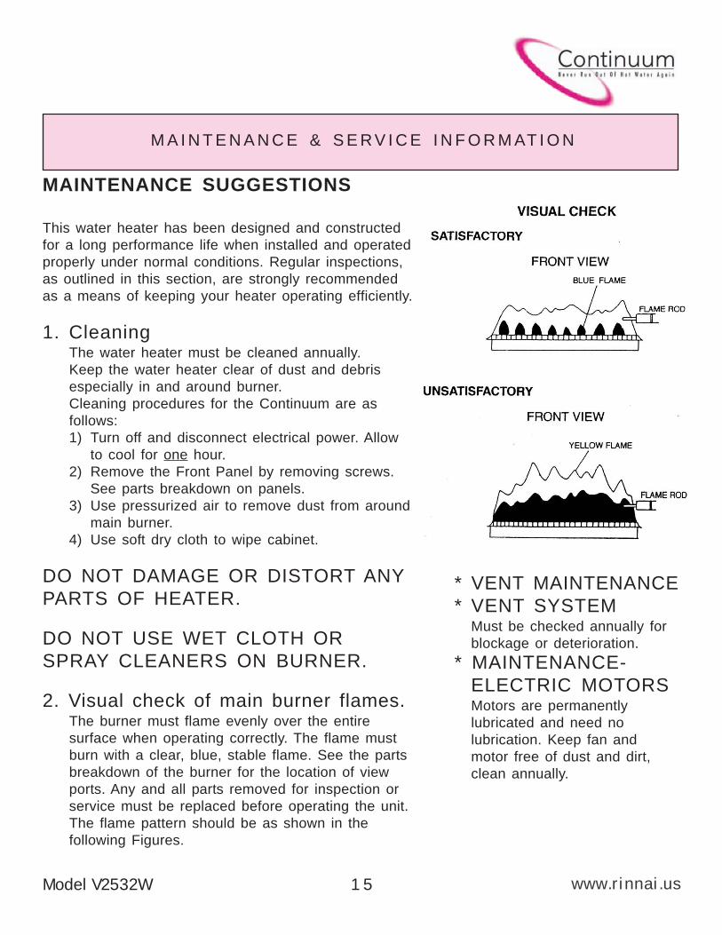
2. Visual check of main burner flames.The burner must flame evenly over the entire
surface when operating correctly. The flame must
burn with a clear, blue, stable flame. See the parts
breakdown of the burner for the location of view
ports. Any and all parts removed for inspection or
service must be replaced before operating the unit.
The flame pattern should be as shown in the
following Figures.
* VENT MAINTENANCE
* VENT SYSTEMMust be checked annually for
blockage or deterioration.
* MAINTENANCE-
ELECTRIC MOTORSMotors are permanently
lubricated and need no
lubrication. Keep fan and
motor free of dust and dirt,
clean annually.
M A I N T E N A N C E & S E R V I C E I N F O R M AT I O N
A
TROUBLE SHOOTING AND COMMON QUESTIONS
Q - When I was using the hot water, the water got cold!
A - If you adjusted the flow from the tap to lessen it, you may have gonebelow the minimum flow required. The Continuum V2532W requires 0.5GPM to operate. If you mix the water with a tap and attempt to get atemperature well below the temperature being controlled by the unit, itmay drop the flow below 0.5 GPM. Decrease the temperature suppliedby the Continuum V2532W at the remote control or increase your totalflow.
Q - White smoke comes out of the exhaust!
A - During colder weather when the exhaust temperature is hotter than theair, the exhaust fumes condense producing white steam.
Q - When I open a hot tap. I do not immediately get hot water!
A - Hot water must travel through your plumbing from the ContinuumV2532W to the faucet. This can take up to 2 or more minutes dependingupon your plumbing system. If hot water is disired instantly at the hotwater fixture, a circulaton loop system must be installed. Pleasecontact your plumber for details.
Q - After I turn off the hot water tap, the fan on the Continuum V2532Wcontinues to run!
A - The fan is designed to be on for 65 seconds after the flow of waterstops.This is to ensure constant water temperatures during rapidstarting and stopping, as well as exhausting any residual gas flueproducts from the unit.
www.rinnai.us Model V2532W1 6
A
www.rinnai.usModel V2532W 1 7
not try to
light the burner by hand.
B. BEFORE OPERATING: Smell all around the
appliance area for gas. Be sure to smell next
to the floor because some gas is heavier
than air and will settle on the floor.
WHAT TO DO IF YOU SMELL GAS
• Do not try to light any appliance.
• Do not touch any electric switch, do not
use any phone in your building.
• Immediately call your gas supplier from a
neighbor’s phone. Follow the gas
supplier’s instructions.
FOR YOUR SAFETY READ BEFORE OPERATING
• If you cannot reach your gas supplier, call
the fire department.
C. Use only your hand to operate remote
control keypad. Never use tools. If the
remote keypad doesn’t work, do not try to
repair it, call a qualified service technician.
Force or attempted repair may result in a
fire or explosion.
D. Do not use this appliance if any part has
been under water. Immediately call a
qualified service technician to inspect the
appliance and to replace any part of the
control system and any gas control which
has been under water.
6) Wait (5) minutes to clear out any gas. If
you then smell gas, STOP! Follow “B” in
the safety information above on this label.
If you don’t smell gas, go to next step.
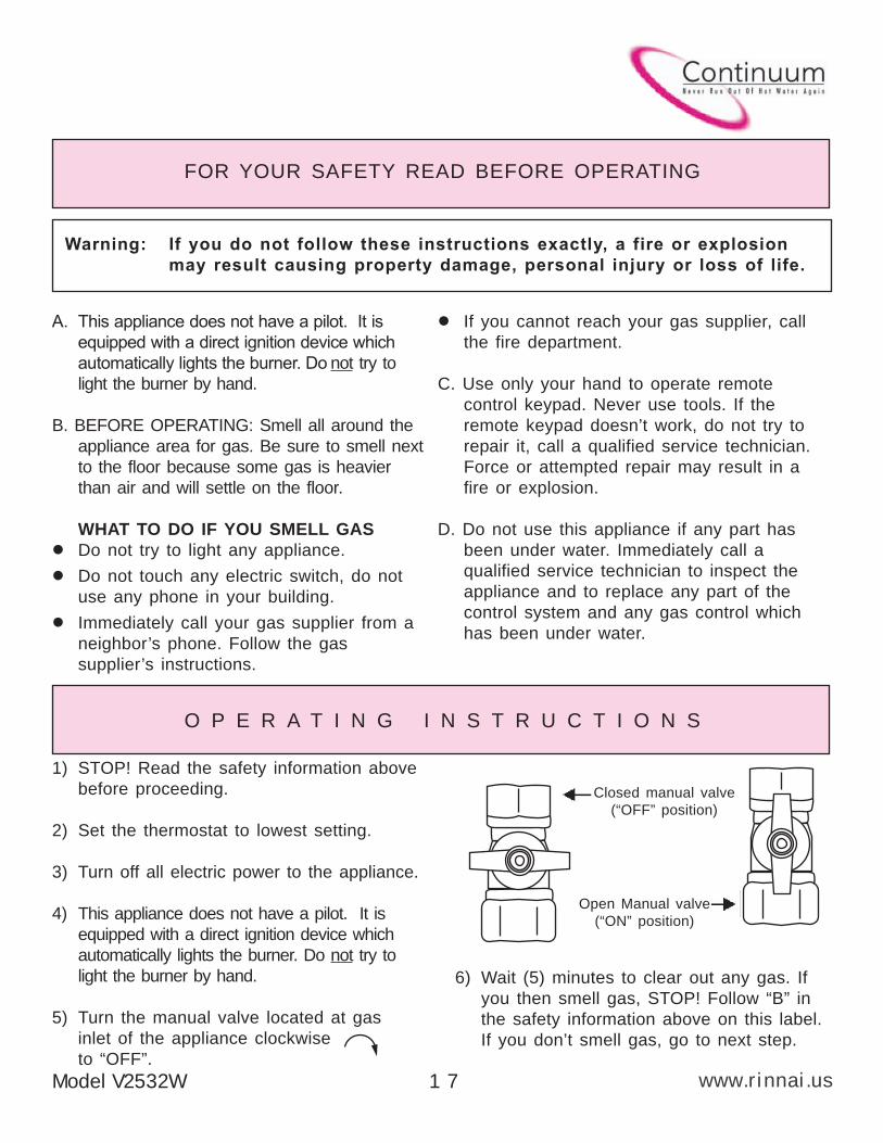
(“OFF” position)
Open Manual valve
(“ON” position)
1) STOP! Read the safety information above
before proceeding.
2) Set the thermostat to lowest setting.
3) Turn off all electric power to the appliance.
4) This appliance does not have a pilot. It is
equipped with a direct ignition device which
automatically lights the burner. Do not try to
light the burner by hand.
5) Turn the manual valve located at gas
inlet of the appliance clockwise
to “OFF”.
O P E R A T I N G I N S T R U C T I O N S
Closed manual valve
A
www.rinnai.us Model V2532W1 8
O P E R A T I N G I N S T R U C T I O N S
C A R E & L I M E C O N D I T I O N W A R N I N G
7) Turn the manual valve located at the gas
inlet of appliance counterclockwise
to “ON”.
8) Turn on all electric power to the appliance.
9) Set thermostat to desired setting.
10) If the appliance will not operate,
Follow the instructions “To Turn Off
Gas To Appliance” and call your
service technician or gas supplier.
To Turn Off Gas To Appliance
1) Set the thermostat to lowest setting.
2) Turn off all electric power to the appliance if service is to be performed.
3) Turn the manual valve at gas inlet of appliance clockwise to “OFF”
Care of Unit’s Exterior:
Keep the exterior cabinet clean. Use a soft cloth and warm water when cleaning the cabinet.
Do Not use volatile substances such as benzene and thinners, as they may ignite, or cause
fading of the paint.
Lime Condition Warning Signal:
If you notice “LC” flashing on the remote key pad, this means the unit is beginning to lime up,
and MUST be flushed. Contact a qualified Rinnai service technician to flush the appliance.
Failure to flush the appliance when “LC” is flashing, will cause damage to the heat exchanger.
Damage caused by lime build up is not covered by the unit’s warranty.
A
www.rinnai.us
C A R E & L I M E C O N D I T I O N W A R N I N G
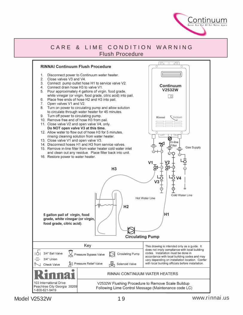
Flush Procedure
In
V2532W
V2532W
Model V2532W 1 9
Installer’s Instructions
All Rinnai water heaters MUST be installed by a state qualified orlicensed contractor. Failure to comply with your local and state codespertaining to water heater installations will void the warranty on saidwater heater(s). It is the responsibility of the person having the unitinstalled to ensure the contractor has the proper licences and permitsfor his state. In addition to the above, Rinnai requires all contractorsattend a product knowledge class before installing our water heaters.This requirement MUST be met in order for your product’s warranty tobe valid. Failure to comply with your local and state codes will resultin non-compliance and void the warranty of the product beinginstalled.
www.rinnai.us
Warnings ............................................................ 21Performance Data ............................................. 22Locating the Unit ............................................... 23Dimensions ........................................................ 23Recommended Piping for Installation ...... 24 - 26Gas Piping Sizing Charts ................................. 27Gas Piping Notes .............................................. 28Water Piping Notes ........................................... 29Pressure Relief Valve ....................................... 29
Contents of Installer’s ManualElectrical Connection Notes ............................. 30Wiring Diagram ............................................ 31,32Lighting the Unit ................................................ 33Remote Controls .......................................... 34,35Initial Operation and Testing ............................ 36Diagnostic Points .............................................. 37Schematic Diagram ........................................... 38Exploded View ........................................... 39 - 42Parts List ................................................... 43 - 47
THE RINNAI V2532W SERIES WATER HEATERS ARE DESIGNCERTIFIED TO THE ANS Z21.10.3CSA 4.3 STANDARD FORCOMMERCIAL WATER HEATERS AND MUST BE INSTALLEDACCORDING TO THESE INSTRUCTIONS. THE WATERHEATERS ARE DESIGN CERTIFIED BY CSA INTERNATIONAL.
A
www.rinnai.usModel V2532W 2 1
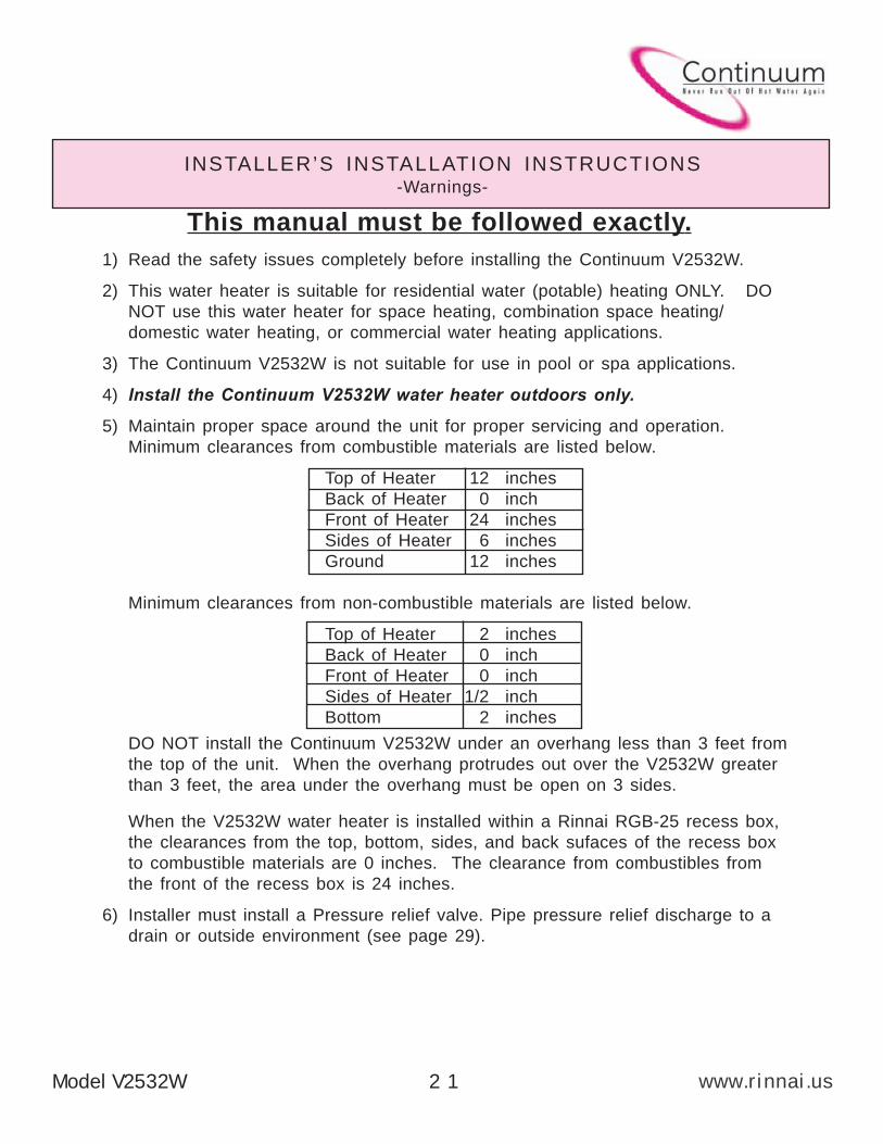
This manual must be followed exactly.
1) Read the safety issues completely before installing the Continuum V2532W.
2) This water heater is suitable for residential water (potable) heating ONLY. DO
NOT use this water heater for space heating, combination space heating/
domestic water heating, or commercial water heating applications.
3) The Continuum V2532W is not suitable for use in pool or spa applications.
4) Install the Continuum V2532W water heater outdoors only.
5) Maintain proper space around the unit for proper servicing and operation.
Minimum clearances from combustible materials are listed below.
Top of Heater 12 inches
Back of Heater 0 inch
Front of Heater 24 inches
Sides of Heater 6 inches
Ground 12 inches
Minimum clearances from non-combustible materials are listed below.
Top of Heater 2 inches
Back of Heater 0 inch
Front of Heater 0 inch
Sides of Heater 1/2 inch
Bottom 2 inches
DO NOT install the Continuum V2532W under an overhang less than 3 feet from
the top of the unit. When the overhang protrudes out over the V2532W greater
than 3 feet, the area under the overhang must be open on 3 sides.
When the V2532W water heater is installed within a Rinnai RGB-25 recess box,
the clearances from the top, bottom, sides, and back sufaces of the recess box
to combustible materials are 0 inches. The clearance from combustibles from
the front of the recess box is 24 inches.
6) Installer must install a Pressure relief valve. Pipe pressure relief discharge to a
drain or outside environment (see page 29).
INSTALLER’S INSTALLATION INSTRUCTIONS-Warnings-
A
www.rinnai.us
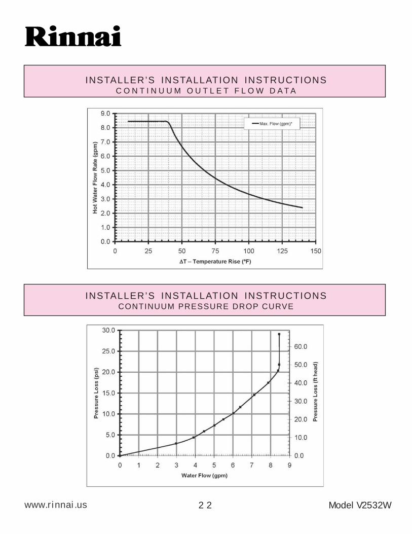
INSTALLER’S INSTALLATION INSTRUCTIONSC O N T I N U U M O U T L E T F L O W D A T A
INSTALLER’S INSTALLATION INSTRUCTIONSCONTINUUM PRESSURE DROP CURVE
Model V2532W2 2

A
www.rinnai.us
INSTALLER’S INSTALLATION INSTRUCTIONSLocating the unit
Installation clearances Minimum
A.......Ver t ica l ly be low an openable window. . . . . . . . . . . . . . . . . . . . . . . . . . . . . . .12”
B.......Vertically above an openable window, door, etc...........................12”
C.......Below eves, porches, overhangs....... . . . . . . . . . . . . . . . . . . . . . . . . . . . . . . . . . . . . . . . .36”
D.......Horizontally from an openable window, door, etc...........................12”
E.......Hor izontal ly between V2532W water heaters. . . . . . . . . . . . . . . . . . . . . . . . . . . .2”
F....... Ver t ica l ly between V2532W water heaters . . . . . . . . . . . . . . . . . . . . . . . . . . . .12”
Continuum V2532W
Door
Eve, porche,
or overhang
Window
AFlue
C/L
C
BD
E
F
INSTALLER’S INSTALLATION INSTRUCTIONSDimensions
Model V2532W 2 3
A
www.rinnai.us
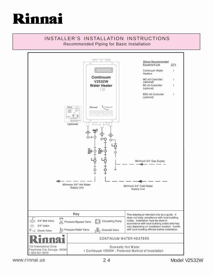
INSTALLER’S INSTALLATION INSTRUCTIONSRecommended Piping for Basic Installation
V2532W
V2532W
Model V2532W2 4
A
www.rinnai.us
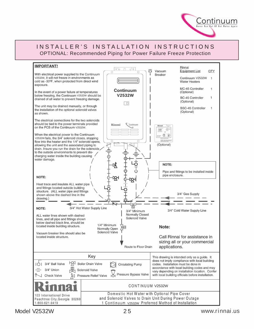
I N S T A L L E R ’ S I N S T A L L A T I O N I N S T R U C T I O N SOPTIONAL: Recommended Piping for Power Failure Freeze Protection
V2532W
V2532W
V2532W
V2532W
V2532W
V2532W
V2532W
V2532W
Model V2532W 2 5
A
www.rinnai.us
INSTALLER’S INSTALLATION INSTRUCTIONSRecommended Piping for Circulation Systems
V2532W
Model V2532W2 6
A
www.rinnai.us
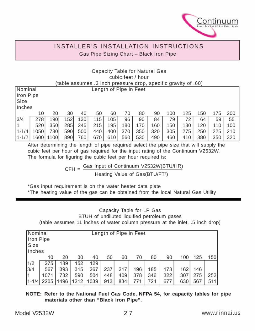
Gas Pipe Sizing Chart – Black Iron Pipe
INSTALLER’S INSTALLATION INSTRUCTIONS
Capacity Table for Natural Gas
cubic feet / hour
(table assumes .3 inch pressure drop, specific gravity of .60)
Nominal Length of Pipe in Feet
Iron Pipe
Size
Inches
10 20 30 40 50 60 70 80 90 100 125 150 175 200
3/4 278 190 152 130 115 105 96 90 84 79 72 64 59 55
1 520 350 285 245 215 195 180 170 160 150 130 120 110 100
1-1/4 1050 730 590 500 440 400 370 350 320 305 275 250 225 210
1-1/2 1600 1100 890 760 670 610 560 530 490 460 410 380 350 320
After determining the length of pipe required select the pipe size that will supply the
cubic feet per hour of gas required for the input rating of the Continuum V2532W.
The formula for figuring the cubic feet per hour required is:
Gas Input of Continuum V2532W(BTU/HR)CFH =
Heating Value of Gas(BTU/FT3)
*Gas input requirement is on the water heater data plate
*The heating value of the gas can be obtained from the local Natural Gas Utility
Capacity Table for LP Gas
BTUH of undiluted liquified petroleum gases
(table assumes 11 inches of water column pressure at the inlet, .5 inch drop)
NOTE: Refer to the National Fuel Gas Code, NFPA 54, for capacity tables for pipe
materials other than “Black Iron Pipe”.
Nominal Length of Pipe in Feet
Iron Pipe
Size
Inches
Model V2532W 2 7
A
www.rinnai.us Model V2532W2 8
INSTALLER’S INSTALLATION INSTRUCTIONSGas Piping Notes
1) A manual gas control valve must be placed upon the gas inlet connection to theContinuum V2532W before it is connected to the gas line. A union can be used onthe connection of the Continuum for the future servicing or disconnection of theunit.
2) Check the type of gas and the gas inlet pressure before connecting the ContinuumV2532W. If the Continuum V2532W is not of the gas type that the building is suppliedwith, DO NOT connect the water heater. Contact the dealer for the proper unit tomatch the gas type.
3) Minimum and Maximum Gas pressures are listed below:* Minimum value is for input adjustment
Natural Gas: *Minimum 7" WC Propane Gas: *Minimum 11" WCMaximum 10.5" WC Maximum 13.5" WC
WARNING: Conversion of this unit from natural gas to propane or propane tonatural gas CANNOT be done in the field.
4) After completion of gas pipe connections, all joints including the heater must bechecked for gas-tightness by means of leak detector solution, soap and water, or anequivalent nonflammable solution, as applicable. Caution: Since some leak testsolutions, including soap and water, may cause corrosion or stress cracking, thepiping must be rinsed with water after testing, unless it has been determined thatthe leak solution is non-corrosive.
5) The Continuum V2532W must be leak tested before it is placed into operation.
6) The Continuum V2532W and its individual shut-off valve must be disconnected fromthe gas supply piping system when pressure testing of the gas supply pipingsystem at test pressures greater than 1/2 psi (3.5 kPa).
7) Always use approved connectors to connect the unit to the gas line. Always purgethe gas line of any debris before connection to the water heater.
8) The Continuum V2532W must be isolated from the gas supply piping system byclosing it's individual manual shutoff valve during any pressure testing of the gassupply piping system at test pressures equal to or less than 1/2 psi (3.5 kPa).
9) The Continuum V2532W's Installation location must provide adequate Combustionand Ventilation airflow.
A
www.rinnai.usModel V2532W 2 9
INSTALLER’S INSTALLATION INSTRUCTIONSWater Piping Notes
1) A manual water control valve must be placed upon the water inlet connection to the Continuum V2532Wbefore it is connected to the water line. Unions may be used on both the hot/cold water supply lines, forthe future servicing or disconnection of the unit.
2) All threaded water piping joints should be made up using Teflon tape, DO NOT use pipe dope.
3) All soldering materials and piping must be compatible with potable water.
4) Purge the water line to remove from it all debris and air. Debris will damage the Continuum V2532W.
5) There is a wire mesh strainer on the Continuum V2532W's inlet to discourage the introduction of debristo the unit. It will need to be cleaned after operating the water heater for the first time, andperiodically thereafter. DO NOT operate unit without filter in place.
WARNING: DO NOT reverse the inlet and outlet (cold and hot water) connections on theunit. This would cause the Continuum V2532W to operate dangerously or not at all.
INSTALLER’S INSTALLATION INSTRUCTIONSPressure Relief Valve
1) ANSI code calls for the addition of an approved pressure relief valve to all water heating systems.
2) The pressure relief valve must meet the following criteria: The relief valve must comply with thestandard for Relief Valves and Automatic Gas Shutoff Devices for Hot Water Supply Systems ANSIZ21. 22 and/or the standard CAN1-4.4 Temperature, Pressure, Temperature and Pressure ReliefValves and Vacuum Relief Valves. This relief valve must be rated at 150 PSI of pressure.
3) The relief valve should be added to the hot water outlet line per manufacturer'sinstructions. DO NOT place any other type valve or shut off device between therelief valve and the hot water heater.
4) The discharge from the pressure relief valve should be piped to the ground or into a drainsystem to prevent exposure or possible burn hazards to humans or other plant or animal life.Water discharged from the relief valve could cause severe burns instantly, scalds and/or death.
5) Do not plug the relief valve and do not install any reducing fittings or other restrictions inthe relief line. The relief line should allow for complete drainage of the valve and the line.
6) If a relief valve discharges periodically, this may be due to thermal expansion in aclosed water supply system. Contact the water supplier or local plumbing inspectoron how to correct this situation. Do not plug the relief valve.
7) Pressure relief valve must be manually operated once a year to check for correct operation.Caution: See Item 4 before manually operating relief valve.
8) Should overheating occur or the gas supply fail to shut off, turn off the manual gasvalve on the Continuum V2532W.
A
www.rinnai.us
INSTALLER’S INSTALLATION INSTRUCTIONS
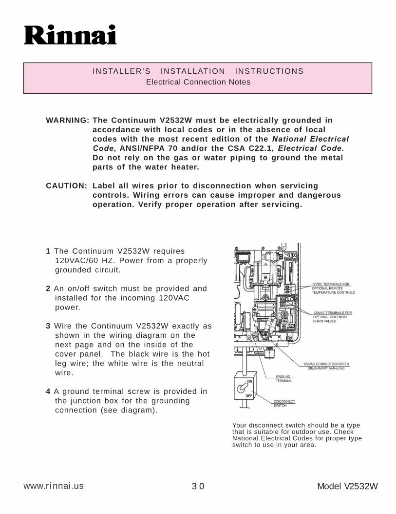
Electrical Connection Notes
WARNING: The Continuum V2532W must be electrically grounded in
accordance with local codes or in the absence of local
codes with the most recent edition of the National ElectricalCode, ANSl/NFPA 70 and/or the CSA C22.1, Electrical Code.
Do not rely on the gas or water piping to ground the metal
parts of the water heater.
CAUTION: Label all wires prior to disconnection when servicing
controls. Wiring errors can cause improper and dangerous
operation. Verify proper operation after servicing.
1 The Continuum V2532W requires
120VAC/60 HZ. Power from a properly
grounded circuit.
2 An on/off switch must be provided and
installed for the incoming 120VAC
power.
3 Wire the Continuum V2532W exactly as
shown in the wiring diagram on the
next page and on the inside of the
cover panel. The black wire is the hot
leg wire; the white wire is the neutral
wire.
4 A ground terminal screw is provided in
the junction box for the grounding
connection (see diagram).
Your disconnect switch should be a typethat is suitable for outdoor use. CheckNational Electrical Codes for proper typeswitch to use in your area.
Model V2532W3 0

A
www.rinnai.usModel V2532W 3 1
INSTALLER’S INSTALLATION INSTRUCTIONSWiring Diagram
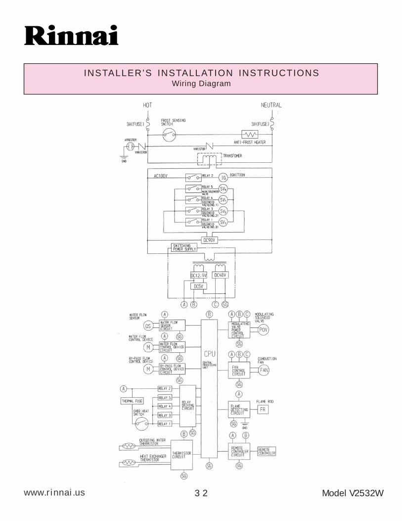
A
www.rinnai.us
INSTALLER’S INSTALLATION INSTRUCTIONSWiring Diagram
Model V2532W3 2
A
www.rinnai.usModel V2532W 3 3
INSTALLER’S INSTALLATION INSTRUCTIONSLighting the Unit
WARNING: If you do not follow these instructions exactly, a fire or
explosion may result causing property damage, personal injury or loss
of life.
1) This water heater does not have a pilot. It is equipped with a direct ignition
device which automatically lights the burner. DO NOT TRY TO LIGHT THE
BURNER BY HAND.
2) Before operating the Continuum V2532W smell all around the unit for gas. Be
sure to smell near the ground as leaking gas may settle there.
3) Turn the manual gas control valve on.
STOP!! READ THE SAFETY ISSUES ON PAGES 8 & 9
4) Turn on any hot water tap. The Continuum V2532W should light and begin
heating your water.
If the Continuum V2532W fails to light
1) DO NOT ATTEMPT TO LIGHT BY HAND.
2) Turn off the electrical power to the unit.
3) Turn off the manual gas control.
4) Wait 5 minutes, if you smell gas, go to a neighbor's house and call the gas
company or the fire department. If you do not smell gas, go to the next step.
5) Turn the manual gas control valve on.
6) Turn the electrical power to the unit on.
7) Turn on any hot water tap.
8) If the unit still fails to light, turn off the electricity and gas to the unit and call
Rinnai 1-800-621-9419.
A
www.rinnai.us
INSTALLER’S INSTALLATION INSTRUCTIONSRemote Controls- General
The remote controls for the Continuum V2532W allow the customer to control the
functions of the water heater and to diagnose certain fault conditions.
The Main Controller model MC-45-4US is intended to be installed in the kitchen or
laundry area where the majority of the hot water is being used.
NOTE: The MC-45-4US has a temperature setpoint range of 96-140°F. This is the
only controller capable of temperature setpoints greater than 120°F.
The Bath Controller model BC-45-4US and Secondary Bath Controller model
BSC-45-4US are intended to be installed in a bath room close to a shower or
tub. Both of these controllers have temperature setpoint ranges of 96-120°F.
NOTE: Only one of each type of controller can be connected to one Continuum
V2532W water heater. (i.e. Installations with two MC-45-4US, two BC-45-4US,
or two BSC-45-4US controllers will not function properly.)
Before installing the remote controls, determine the most convenient location(s).
When deciding on the best location for the remote controls, please consider the
following items:
1) Place the controllers out of reach of small children.
2) Avoid locations where the controller(s) will become hot. (over the stove, near
the oven or a radiant heater.
3) Avoid direct sunlight. (The digital monitor can be difficult to read in direct
sunlight)
4) Avoid areas where the remote can be splashed with cooking water, oil or
sauce.
5) The remote control cables carry low voltage, 12VDC digital.
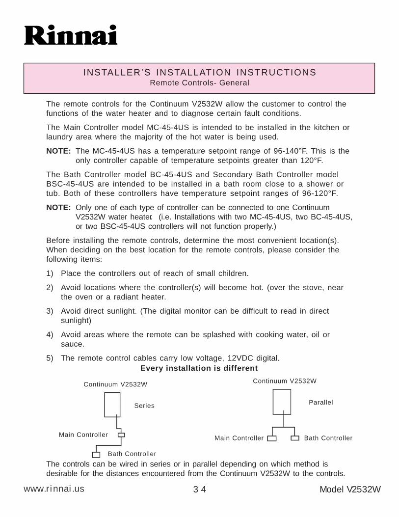
The controls can be wired in series or in parallel depending on which method is
desirable for the distances encountered from the Continuum V2532W to the controls.
Every installation is different
Continuum V2532W
Main ControllerMain Controller
Bath Controller
Bath Controller
Continuum V2532W
SeriesParallel
3 4 Model V2532W
A
www.rinnai.us
INSTALLER’S INSTALLATION INSTRUCTIONSRemote Controls - Installation
1) Determine a suitable location for the
control.
2) Make three holes on the wall as
shown.
3) Run the cable between the control
and the Continuum V2532W or the
control and the other control.
4) Remove the face plate from the
remote control, using a screw driver.
5) Connect the cable to the remote control.
6) Mount the control to the wall using the holes drilled in step 2.
Note: If the cable cannot be run in the wall cavity, the plastic knockout should be
removed from the top or bottom of the control to allow flush mounting with
the wall
7) Disconnect the power from the Continuum V2532W.
8) Remove the cover of the Continuum V2532W.
9) Remove the plastic cover from the PCB and electrical connections.
DO NOT ATTEMPT TO CONNECT THE REMOTE CONTROLS WITH THE POWER ON,
THERE'S 120 VOLT POTENTIAL, NEXT TO THE REMOTE CONTROL CONNECTIONS
INSIDE THE UNIT. DO NOT CONNECT THE REMOTE CONTROL TO THE 120VAC
TERMINALS PROVIDED FOR THE OPTIONAL SOLENOID DRAIN VALVES. All service
and wiring should be performed by a certified installer.
10) Thread the cable through the
access hole at the base of the unit
and connect the wires to the control
terminals labeled “TERMINALS
FOR CONTROLS” on the right
hand side bottom of the PCB.
11) Secure the control cable using the
clamp provided.
12) Replace plastic cover over PCB and
then replace the cover of the
Continuum V2532W.
Model V2532W 3 5
A
www.rinnai.us Model V2532W3 6
INSTALLER’S INSTALLATION INSTRUCTIONSInitial Operation and Testing
1) Turn on the gas and water.
2) Check for water and gas leaks. Use soapy water to test for gas leaks.
3) Remove pressure test point screw, attach pressure gauge to test point.
4) Turn Power on.
5) Open any hot water tap fully.
6) Check test point or supply pressure in water columns per inch.
Manifold Pressure: Supply pressure:
Natural Gas 3.4" Hi. fire 0.56" Lo. fire Natural Gas Min. 6" Max. 10.5"
LPG 5.1" Hi. fire 0.88" Lo. fire LPG Min. 10" Max. 13.5"
NOTE: The pressure may be low due to too little flow, too high an incoming
temperature, and/or undersized gas piping. Examine these areas before
determining that the pressure needs to be adjusted. Contact Rinnai before
adjusting manifold pressures at 1-800-621-9419. Failure to contact Rinnai,
could void unit’s warranty.
7) If it is determined that the gas pressure needs adjusting, first check the in
coming pressure at the test point on the gas inlet. If it is correct follow the
adjusting procedure contained in the pouch of the unit EXACTLY. If in doubt
call Rinnai 1-800-621-9419.
The regulator is pre-set at the factory, it should not need resetting.
8) Turn the hot water off. Turn the power off. Remove the pressure guage and
replace the test point screw. Check for a gas leak around the test point
screw.
9) Replace the front cover.
10) Turn the power back on.
11) Check the operation of the unit (run for a minimum of 15 minutes). Check
the operation of each of the remote controls. Check the operation of the
Power failure protection system.
12) Isolate the water heater from the hot and cold water lines, then remove and
clean the inlet water filter screen. Place the water filter back into the water
heater and tighten. Open the hot and cold water lines to the water heater
and test the operation of the unit.
13) Explain the proper operation of the Continuum V2532W to the customer.
A
www.rinnai.usModel V2532W 3 7
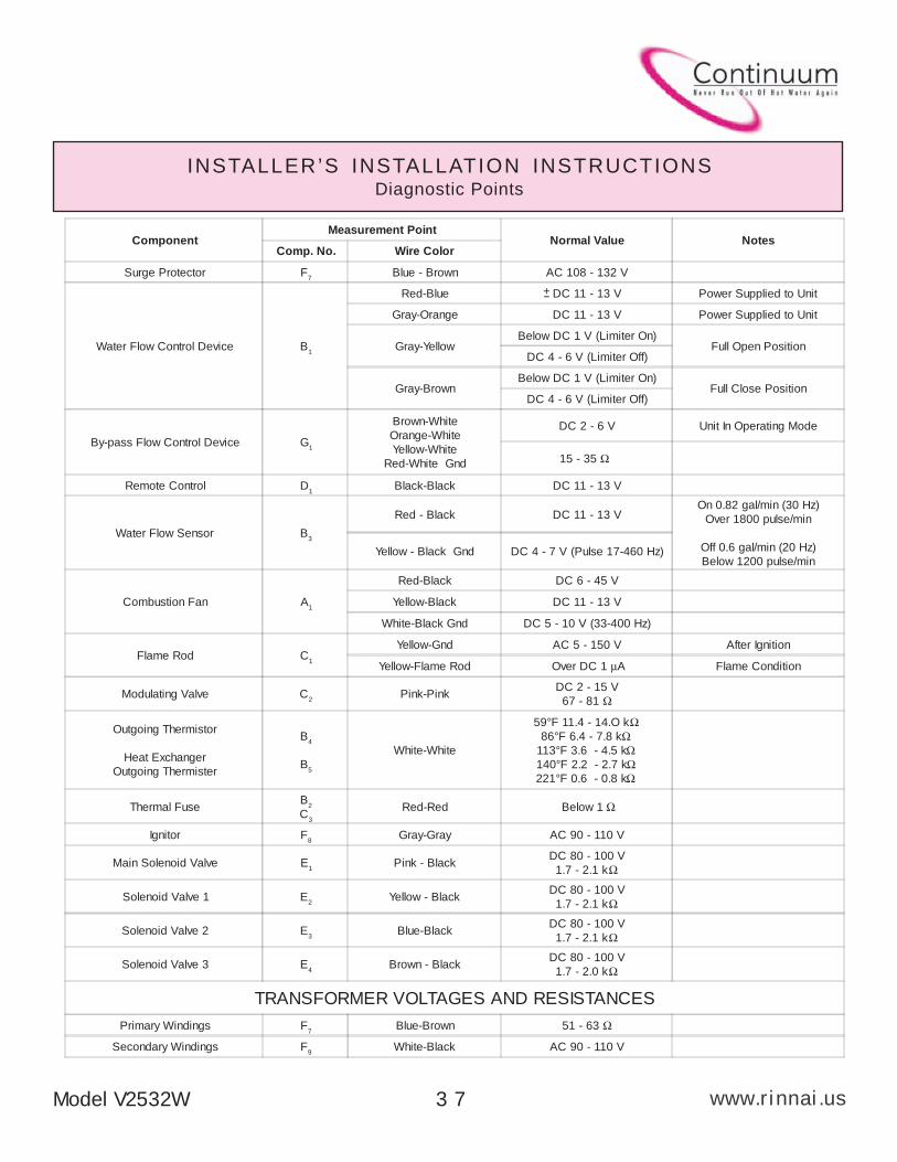
INSTALLER’S INSTALLATION INSTRUCTIONSDiagnostic Points
ComponentMeasurement Point
Normal Value NotesComp. No. Wire Color
Surge Protector F7
Blue - Brown AC 108 - 132 V
Water Flow Control Device B1
Red-Blue DC 11 - 13 V Power Supplied to Unit
Gray-Orange DC 11 - 13 V Power Supplied to Unit
Gray-YellowBelow DC 1 V (Limiter On)
Full Open PositionDC 4 - 6 V (Limiter Off)
Gray-BrownBelow DC 1 V (Limiter On)
Full Close PositionDC 4 - 6 V (Limiter Off)
By-pass Flow Control Device G1
Brown-White
Orange-White
Yellow-White
Red-White Gnd
DC 2 - 6 V Unit In Operating Mode
15 - 35 Ω
Remote Control D1
Black-Black DC 11 - 13 V
Water Flow Sensor B3
Red - Black DC 11 - 13 VOn 0.82 gal/min (30 Hz)
Over 1800 pulse/min
Off 0.6 gal/min (20 Hz)
Below 1200 pulse/minYellow - Black Gnd DC 4 - 7 V (Pulse 17-460 Hz)
Combustion Fan A1
Red-Black DC 6 - 45 V
Yellow-Black DC 11 - 13 V
White-Black Gnd DC 5 - 10 V (33-400 Hz)
Flame Rod C1
Yellow-Gnd AC 5 - 150 V After Ignition
Yellow-Flame Rod Over DC 1 µA Flame Condition
Modulating Valve C2
Pink-PinkDC 2 - 15 V
67 - 81 Ω
Outgoing Thermistor
Heat Exchanger
Outgoing Thermister
B4
B5
White-White
59°F 11.4 - 14.O k Ω 86°F 6.4 - 7.8 kΩ
113°F 3.6 - 4.5 kΩ 140°F 2.2 - 2.7 kΩ 221°F 0.6 - 0.8 kΩ
Thermal FuseB
2
C3
Red-Red Below 1 Ω
Ignitor F8
Gray-Gray AC 90 - 110 V
Main Solenoid Valve E1
Pink - BlackDC 80 - 100 V
1.7 - 2.1 kΩ
Solenoid Valve 1 E2
Yellow - BlackDC 80 - 100 V
1.7 - 2.1 kΩ
Solenoid Valve 2 E3
Blue-BlackDC 80 - 100 V
1.7 - 2.1 kΩ
Solenoid Valve 3 E4
Brown - BlackDC 80 - 100 V
1.7 - 2.0 kΩ
TRANSFORMER VOLTAGES AND RESISTANCES
Primary Windings F7
Blue-Brown 51 - 63 Ω
Secondary Windings F9
White-Black AC 90 - 110 V
+-
A
www.rinnai.us
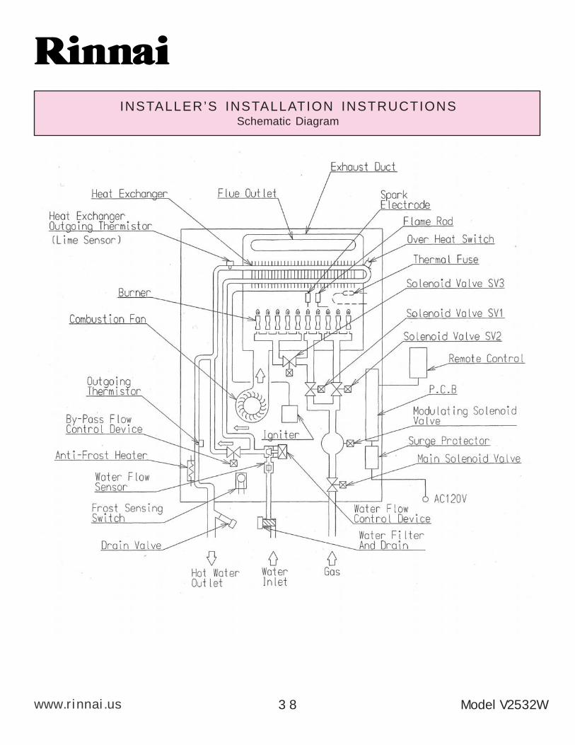
INSTALLER’S INSTALLATION INSTRUCTIONSSchematic Diagram
Model V2532W3 8
A
www.rinnai.us
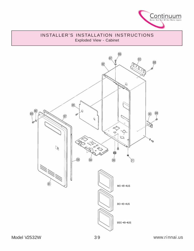
INSTALLER’S INSTALLATION INSTRUCTIONSExploded View - Cabinet
Model V2532W 3 9
A
www.rinnai.us
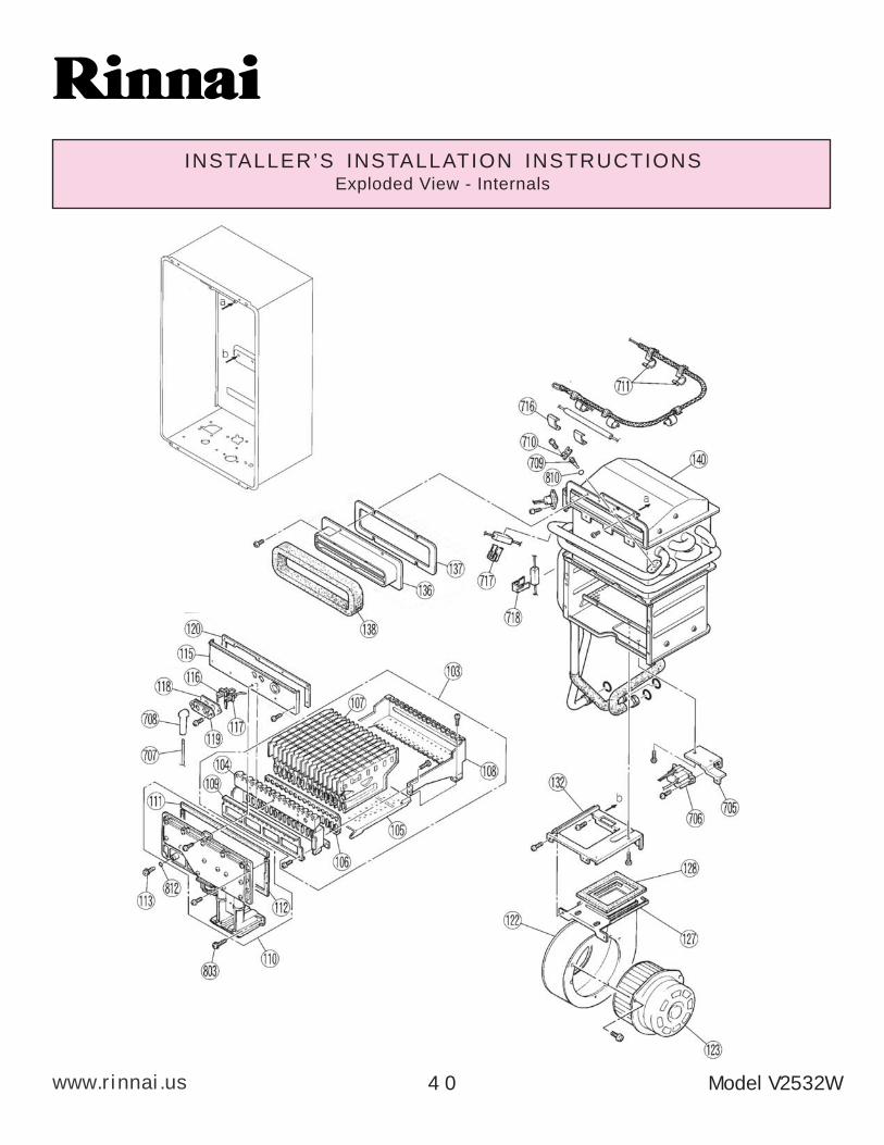
INSTALLER’S INSTALLATION INSTRUCTIONSExploded View - Internals
Model V2532W4 0
A
www.rinnai.us
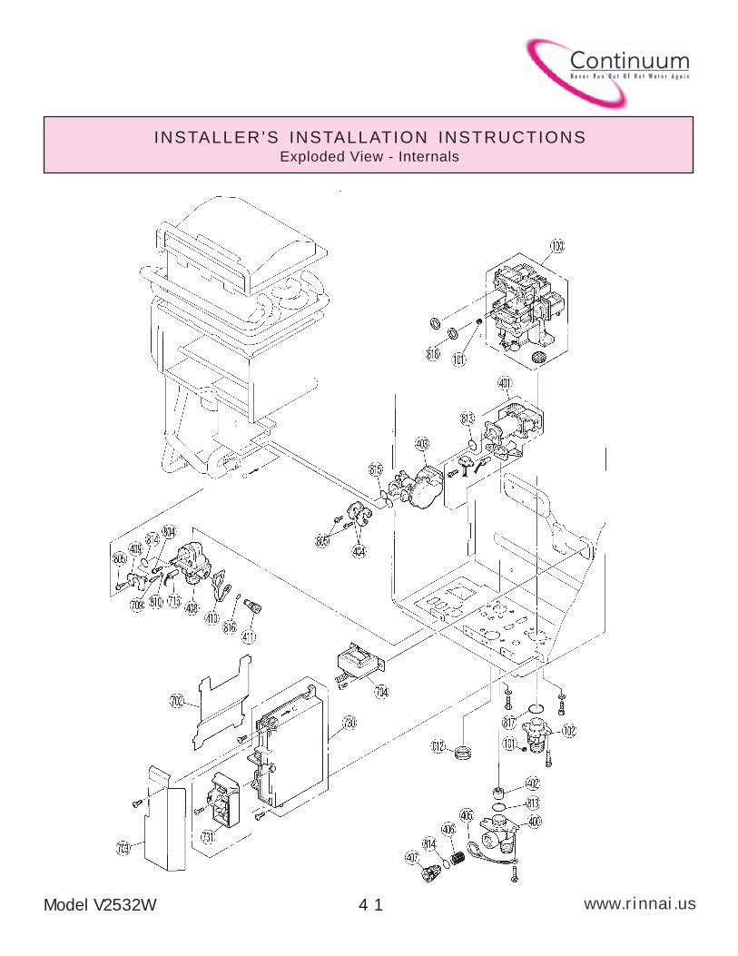
INSTALLER’S INSTALLATION INSTRUCTIONSExploded View - Internals
Model V2532W 4 1
A
www.rinnai.us
INSTALLER’S INSTALLATION INSTRUCTIONSExploded View - Electrical
Model V2532W4 2
A
www.rinnai.usModel V2532W 4 3
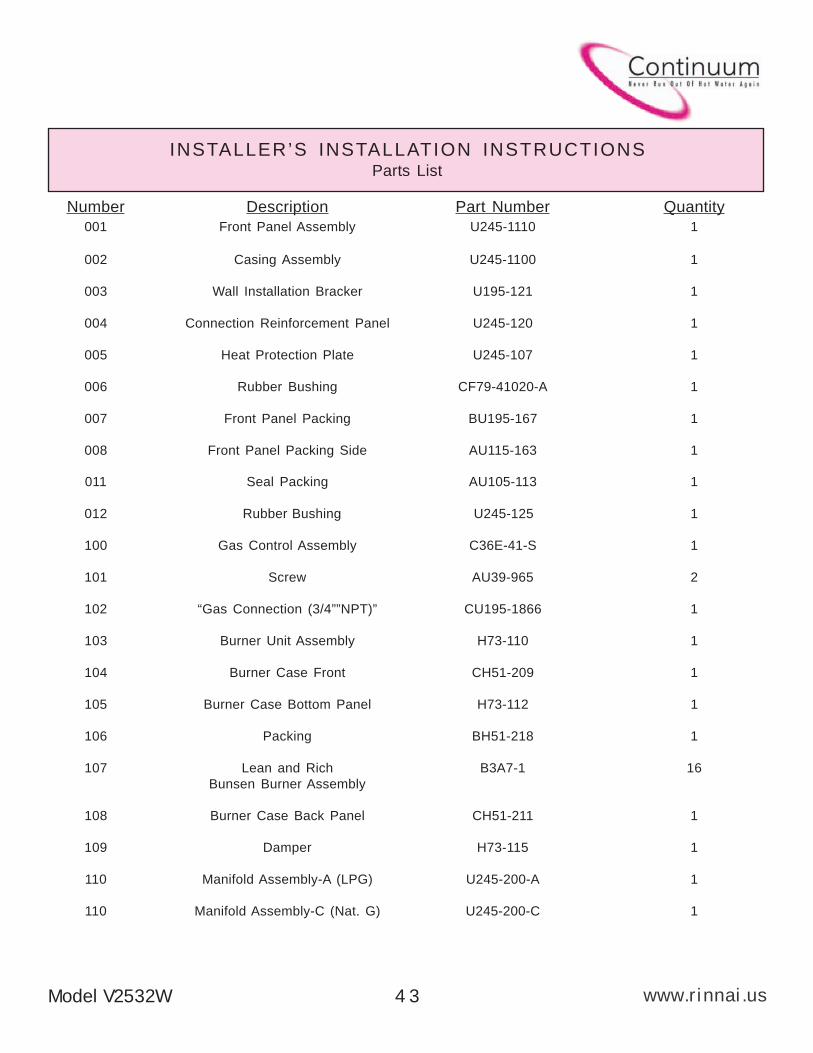
INSTALLER’S INSTALLATION INSTRUCTIONSParts List
Number Description Part Number Quantity
001 Front Panel Assembly U245-1110 1
002 Casing Assembly U245-1100 1
003 Wall Installation Bracker U195-121 1
004 Connection Reinforcement Panel U245-120 1
005 Heat Protection Plate U245-107 1
006 Rubber Bushing CF79-41020-A 1
007 Front Panel Packing BU195-167 1
008 Front Panel Packing Side AU115-163 1
011 Seal Packing AU105-113 1
100 Gas Control Assembly C36E-41-S 1
101 Screw AU39-965 2
102 “Gas Connection (3/4””NPT)” CU195-1866 1
103 Burner Unit Assembly H73-110 1
104 Burner Case Front CH51-209 1
105 Burner Case Bottom Panel H73-112 1
106 Packing BH51-218 1
107 Lean and Rich B3A7-1 16
Bunsen Burner Assembly
108 Burner Case Back Panel CH51-211 1
109 Damper H73-115 1
110 Manifold Assembly-A (LPG) U245-200-A 1
110 Manifold Assembly-C (Nat. G) U245-200-C 1
012 Rubber Bushing U245-125 1
A
www.rinnai.us Model V2532W4 4
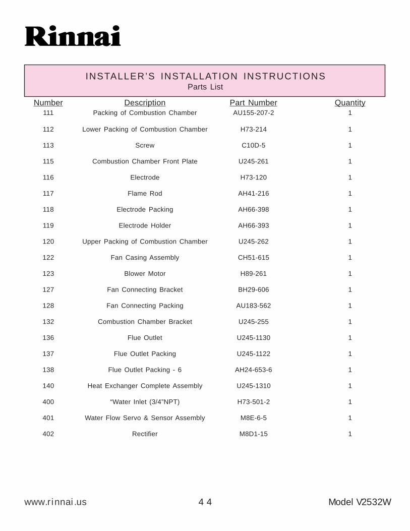
INSTALLER’S INSTALLATION INSTRUCTIONSParts List
Number Description Part Number Quantity
111 Packing of Combustion Chamber AU155-207-2 1
112 Lower Packing of Combustion Chamber H73-214 1
113 Screw C10D-5 1
115 Combustion Chamber Front Plate U245-261 1
116 Electrode H73-120 1
117 Flame Rod AH41-216 1
118 Electrode Packing AH66-398 1
119 Electrode Holder AH66-393 1
120 Upper Packing of Combustion Chamber U245-262 1
122 Fan Casing Assembly CH51-615 1
123 Blower Motor H89-261 1
127 Fan Connecting Bracket BH29-606 1
128 Fan Connecting Packing AU183-562 1
132 Combustion Chamber Bracket U245-255 1
136 Flue Outlet U245-1130 1
137 Flue Outlet Packing U245-1122 1
138 Flue Outlet Packing - 6 AH24-653-6 1
140 Heat Exchanger Complete Assembly U245-1310 1
400 “Water Inlet (3/4”NPT) H73-501-2 1
401 Water Flow Servo & Sensor Assembly M8E-6-5 1
402 Rectifier M8D1-15 1
A
www.rinnai.usModel V2532W 4 5
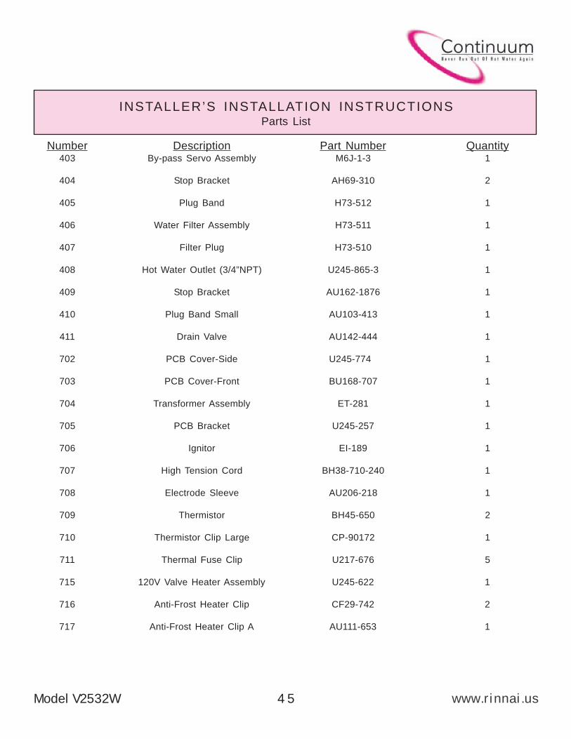
INSTALLER’S INSTALLATION INSTRUCTIONSParts List
Number Description Part Number Quantity403 By-pass Servo Assembly M6J-1-3 1
404 Stop Bracket AH69-310 2
405 Plug Band H73-512 1
406 Water Filter Assembly H73-511 1
407 Filter Plug H73-510 1
408 Hot Water Outlet (3/4”NPT) U245-865-3 1
409 Stop Bracket AU162-1876 1
410 Plug Band Small AU103-413 1
411 Drain Valve AU142-444 1
702 PCB Cover-Side U245-774 1
703 PCB Cover-Front BU168-707 1
704 Transformer Assembly ET-281 1
705 PCB Bracket U245-257 1
706 Ignitor EI-189 1
707 High Tension Cord BH38-710-240 1
708 Electrode Sleeve AU206-218 1
709 Thermistor BH45-650 2
710 Thermistor Clip Large CP-90172 1
711 Thermal Fuse Clip U217-676 5
715 120V Valve Heater Assembly U245-622 1
716 Anti-Frost Heater Clip CF29-742 2
717 Anti-Frost Heater Clip A AU111-653 1

A
www.rinnai.us Model V2532W4 6
INSTALLER’S INSTALLATION INSTRUCTIONSParts List
Number Description Part Number Quantity
718 Anti-Frost Heater Clip AU100-721 1
720 Power Supply Harness AU195-1876 1
721 Fuse Harness BU195-1630 1
722 100V Harness U245-601 1
723 Solenoid Valve Harness U245-602 1
725 Thermal Fuse Harness U245-610 1
726 Mold-Type Over Heat Switch BU129-824-2 1
730 PCB U245-1200 1
731 Surge Protector BU195-1873 1
732 Frost Sensing Switch H73-750 1
733 120V Anti-Frost Heater Assembly U245-1320 1
734 Sensor Harness - 2 U245-603-2 1
802 Washer AU33-184 4
803 Screw CP-21478-412 3
804 Screw U217-449 1
805 Screw ZAA0408UK 3
806 Screw ZBD0508UK 2
807 Screw AU48-174 2
808 Screw ZBA0510UK 4
809 Screw ZAD0408TK 4
810 O-ring M10B-2-4 2
812 O-ring M10B-13-4 1
813 O-ring M10B-2-18 2
A
www.rinnai.usModel V2532W 4 7
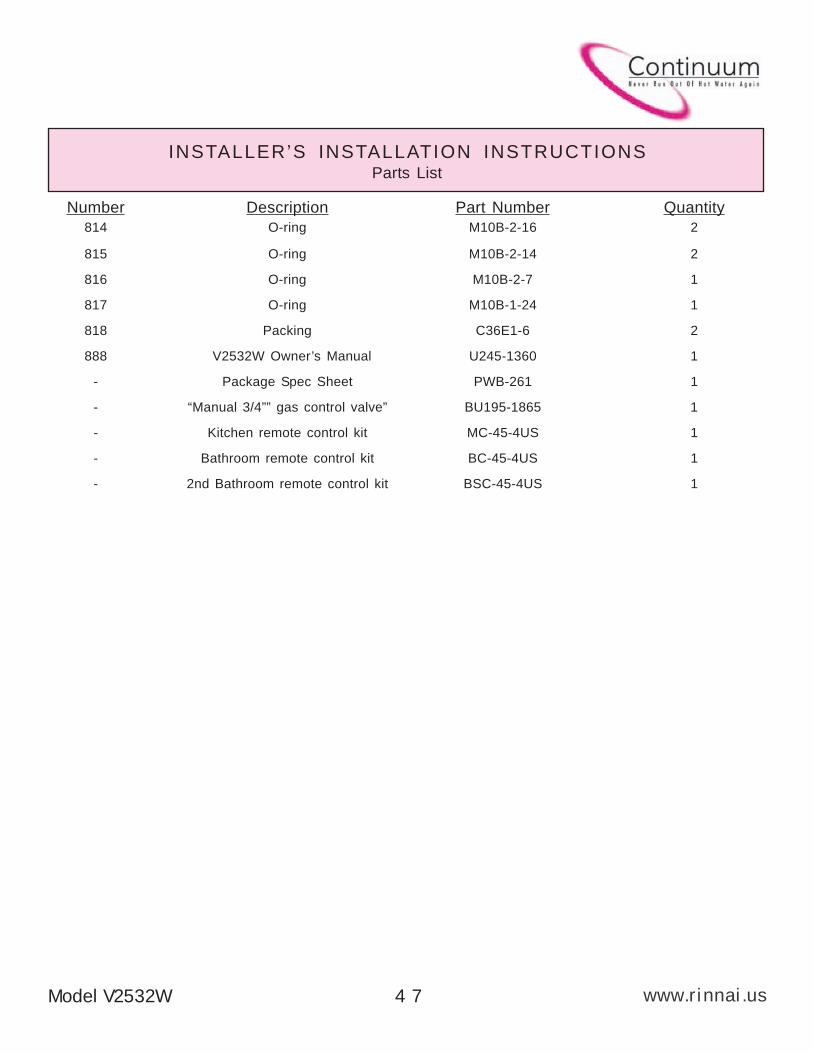
INSTALLER’S INSTALLATION INSTRUCTIONSParts List
Number Description Part Number Quantity
814 O-ring M10B-2-16 2
815 O-ring M10B-2-14 2
816 O-ring M10B-2-7 1
817 O-ring M10B-1-24 1
818 Packing C36E1-6 2
888 V2532W Owner’s Manual U245-1360 1
- Package Spec Sheet PWB-261 1
- “Manual 3/4”” gas control valve” BU195-1865 1
- Kitchen remote control kit MC-45-4US 1
- Bathroom remote control kit BC-45-4US 1
- 2nd Bathroom remote control kit BSC-45-4US 1
A
www.rinnai.uswww.rinnai.us U245-1360 01
Printed in Japan 2003.05
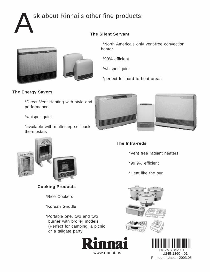
Ask about Rinnai’s other fine products:
The Energy Savers
*Direct Vent Heating with style and
performance
*whisper quiet
*available with multi-step set back
thermostats
The Infra-reds
*Vent free radiant heaters
*99.9% efficient
*Heat like the sun
Cooking Products
*Rice Cookers
*Korean Griddle
*Portable one, two and two
burner with broiler models.
(Perfect for camping, a picnic
or a tailgate party
The Silent Servant
*North America’s only vent-free convection
heater
*99% efficient
*whisper quiet
*perfect for hard to heat areas